SYNERGY DMA DUAL MONO POWER AMPLIFIER BY TUBE …
32
SYNERGY DMA DUAL MONO POWER AMPLIFIER BY TUBE TECHNOLOGY ~ USER'S MANUAL ~ TT PART No. Sy2M-01 Printed in England 1st Edition - September 1995 i
Transcript of SYNERGY DMA DUAL MONO POWER AMPLIFIER BY TUBE …

SYNERGY DMADUAL MONO
POWER AMPLIFIERBY TUBE TECHNOLOGY
~ USER'S MANUAL ~
TT PART No. Sy2M-01
Printed in England1st Edition - September1995
i

ii
Synergy -(defn); Simultaneous action of separate instanceswhich, together have a greater total effect then the sum oftheir individual accomplishments.
The Synergy
Introduction Thank you for selecting the Synergy Amplifier from Tube Technology.
We hope The Synergy will bring you many years of pleasure as an important part of your hi-fisystem.
Please read through this manual so you will know how to operate your Synergy amplifierproperly. After you have finished reading this manual, please put it away in a safe place forfuture reference.
Please do not forget to complete and return the enclosed registration card.
We wish you many hours of musical enjoyment !
iii

Contents 1.
2.
3.
4.
5.
6.
7.
8.9.
10.
Getting StartedUnpacking your Synergy AmplifierChecking and Installing the tubesMains ConnectionConnecting the Synergy to the household mains supplyWiring a Mains Plug - UKInstallationInstalling & ventilation of your amplifierAudio Connection - Rear PanelConnecting the Synergy's InputsConnecting your Synergy to the loudspeakersOperating your System - Front PanelSwitching your amplifier On & OffControl & Front Panel FunctionsOperational NotesRunning-InBurning in your AmplifierTube InformationMaintenanceCare and Cleaning of your amplifierAdjusting Bias using the OBBC systemTroubleshootingSpecificationsGuaranteeClaims under the GuaranteeTube Renaissance
12-4
56
7
89-10
1112-1314
1515
1616-17181920-2121-2223-27
Contents - 1
Conventions This manual uses the following conventions;
Bold indicates emphasis or a minor heading.
Italic Bold refers to a sub heading of a chapter.
This symbol refers to Notes containing important information set off from the text.
THIS SYMBOL REFERS TO CAUTION MESSAGES AND PROCEDURES WHICH IFNOT OBSERVED CAN LEAD TO DAMAGE OR INJURY
Contents - 2

Getting Started 1
GettingStarted This chapter contains information on;
Unpacking your Synergy Amplifier
Checking & Installing the Vacuum Tubes
Your amplifier is packed in "jiffy-cell" support foam. Grip the top of this foam and simply pull itout of the box. The Synergy is then left sitting on its bottom support. Lift out carefully,remembering that the centre of gravity is biased towards the rear of the unit due to the heavytransformers.(It may be neccessary for another person to help manouvre the unit as it is very heavy)
The following items are included in the packaging of a Synergy No.1;
1 x Synergy DMA Amplifier12 x EL34 Output Vacuum Tubes1 x Bias Adjust trimmer1 x Reference Manual & Registration Card1 x IEC Mains Lead1 x Spare mains fuse (6.3A T) (8.0A T 100V/120V)
Unpacking
All packing should be retained. Amplifiers returned under guarantee are only accepted in theiroriginal packaging.

Getting Started 2
Installingthe Tubes
The Synergy is usually shipped with its output tubes packed separately, this helps protect themduring transit.
If you have ordered a protection grille with your amplifier the output tubes have already beeninstalled and there is no need to read this section.
The input and driver tubes are already in place inside the amplifier, please do not remove these,as they have been calibrated.
The vacant tube sockets on the amplifier are numbered 1 to 6, for the left hand channel of theamplifier and 7 to 12 for the right hand side.(See diagram 1)
The output tubes which are packed separately locate in these sockets. The relevant tube numberis printed on the inside flap of each box, or if you have a Gold Aero model, on the tube caps .Remove the tube carefully from its packing and install it in its matching socket, as labeled inDiagram 1.
Ensure that the keyway on the base of the tube lines up with the keyway on the tube socket.Each tube must be inserted carefully. Align the tube pins in the centre of the receptacles on thetube base, then apply gentle downwards pressure, firmly pushing the tube home into its base.Do not rock the tube from side to side as the keyway on the tube base will fracture.

Getting Started 3
Diagram 1
Master BiasAdjustment
(Left Channel)

Getting Started 4
Remove the tubes from their cartons and fit - one at a time. This will ensure that each tube isin its correct socket as calibrated when leaving the factory. If you should mix up the orderrefer to replacing a tube in the maintenance chapter.
Diagram 2 shows the arrowpointing to the positions ofthe keyways on the EL34and the keyways on theamplifiers tube sockets.
Diagram 2
If the glass on any of the tubes is cracked or broken do not use, consult your dealer for areplacement and refer to the Maintenance chapter for instructions on how to replace a faultytube.
Tube Base Tube Socket
Mains Connection 5
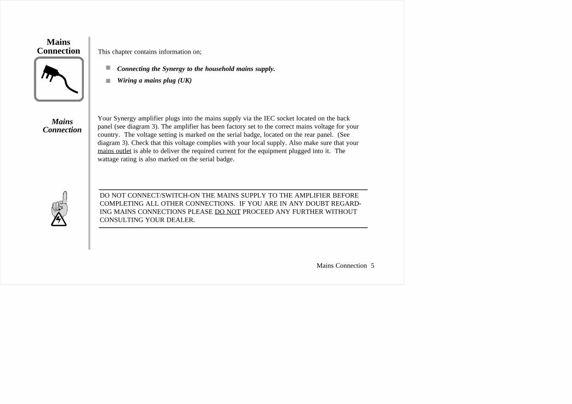
MainsConnection This chapter contains information on;
Connecting the Synergy to the household mains supply.
Wiring a mains plug (UK)
Your Synergy amplifier plugs into the mains supply via the IEC socket located on the backpanel (see diagram 3). The amplifier has been factory set to the correct mains voltage for yourcountry. The voltage setting is marked on the serial badge, located on the rear panel. (Seediagram 3). Check that this voltage complies with your local supply. Also make sure that yourmains outlet is able to deliver the required current for the equipment plugged into it. Thewattage rating is also marked on the serial badge.
MainsConnection
DO NOT CONNECT/SWITCH-ON THE MAINS SUPPLY TO THE AMPLIFIER BEFORECOMPLETING ALL OTHER CONNECTIONS. IF YOU ARE IN ANY DOUBT REGARD-ING MAINS CONNECTIONS PLEASE DO NOT PROCEED ANY FURTHER WITHOUTCONSULTING YOUR DEALER.

Mains Connection 6
Export units for certain markets have a moulded mains plug fitted to comply with localstandards. If your mains supply lead does not have a plug fitted, the coloured wires should beconnected to the appropriate plug terminals in accordance with the following code.
Wire Colour Label on Plug
GREEN/YELLOW E or EARTH orBLUE N or NEUTRAL or BLACKBROWN L or LIVE or RED
If your mains plug has a fuse, please fit a fuse with 13A rating.
If your amplifier is not set correctly for the local supply or if you intend to move the amplifierto a location where the supply is at a different voltage, it will be necessary to change the voltagetaps on the mains transformer. We recommend that this is done by an experienced technician.Refer to changing voltage in the maintenance chapter.
Wiring aMains Plug
DO NOT SWITCH ON THE AMPLIFIERS BEFORE COMPLETING THEAUDIO CONNECTIONS.

Installation 7
InstallationThis chapter contains information on;
Installing and Ventilating your amplifiers
Installing &Vetilation
Ensure that the amplifier is placed in a stable location that is able to accept its weight each unitweighs 46 kilograms.
It is not recommended that amplifiers are installed in cupboards or in any enclosed area if thereis not sufficient air space and ventilation to keep them cool. A minimum distance of six inchesabove the amplifier should be allowed as this is where most of the heat is generated.Dedicated racks are available for housing your tube equipment, contact your dealer or TubeTechnology. Do not locate the amplifier close to radiators or any other heat source, this couldincrease the operating temperature.
Do not locate the amplifier too close to a turntable, as the cartridge could pick up hum from thepower transformers.
THE OUTPUT TUBES REACH VERY HIGH TEMPRATURES!! DO NOT TOUCH UNDERANY CIRCUMSTANCES. FOR EXTRA PRECAUTIONS A TUBE PROTECTION GRILLEIS AVAILABLE.

Audio Connection 8
AudioConnection This chapter contains information on;
Connecting the Synergy's Inputs & Output
Connecting your Synergy to the loudspeakers.
Rear Panel Information
Your amplifier uses high quality connectors to ensure that maximum signal transfer is possible,therefore ensure that all cables used for connection to the amplifier are terminated withconnectors of similar quality.
These connectors for both left and right channels, connect to your preamplifier.
These connectors are safety RCA jacks, which have a negative retractible spring, for the shortcircuit protection of any RCA plug. This allows you to plug and unplug your inter-connectswithout having to switch off the amplifier.
Connectingthe Inputs& Output
AUDIOINPUTS

The Synergy incorporates a special resettable fuse for each of the twelve output tubes. Thisprotects the amplifier from the potential damage that may be caused to the amplifierelectronics if an output tube should go faulty. When activated the fuse stops the tube fromdrawing current, the bias meter will display -1. Please note the filament will still be glowing.
The IEC connector on the rear panel, connects to the mains supply via the mains cablesupplied.
This fuse is rated at 6.3 A, and protects both the large dome shaped transformers.
This switches the amplifier On & Off, it has a red indicator when in the On position.
Audio Connection 9
TUBEPROTECTION
IECINLET
MAINS FUSE
MAINSSWITCH
The loudspeaker outputs are suitable for driving loudspeakers withimpedances in the range of 6-8 ohms. The output terminals are 4mmterminal posts and each will except two 4mm (banana) plugs or bare wire.For bi-wiring use the side entry holes together with the front entry holes.Connect the positive or (+) of the speaker cable to the red terminal on theamplifier, and the negative or (-) to the black terminal on the amplifier.
DO NOT SWITCH-ON THE SYSTEM UNTIL YOU HAVE READ CHAPTER 5 OperatingYour System.
Connection toLoudspeakers

Audio Connection 10
Diagram 3
Rear Panel

Operating your System 11
Operatingyour System This chapter contains information on;
SwitchingOn & Off
Switching your amplifier ON and OFF.
Control & Front Panel Functions
Operational Notes
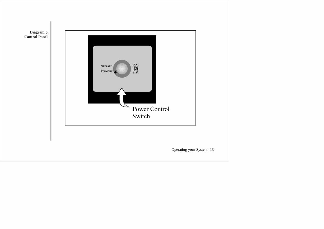
The main switch for switching the Synergy On & Off is located on the rear panel,(See diagram 3) it has a red indicator strip to indicate the On position. With this switch in TheON position, the unit can now be operated from the switch in the centre of the control panel.OPERATE indicates operation of the unit and STANDBY switches the amplifier Off.
Front Panel
Diagram 4
Operating your System 12
After switch on there is a delay of approx. 15 seconds before the main HT is switched, eachchannel is switched On separately, an audible thump is heard from the mains transformer oneach channel as they power up, this is due to pole reversal which is quite normal for large powertransformers. The indicators on the front panel change from Amber to Green as each channel ispowered up.
These LED's are bi-colour and are illuminated in either two colours. GREEN indicates that theunit is switched on and functional, AMBER indicates that the unit is in Standby.
Left & RightStatus Indicators
Front PanelFunctions
Operating your System 13
Diagram 5Control Panel

Some users of tube amplifiers believe that because tube amplifiers take some time to warm upthat they should be left on all the time. The Synergy amplifier reaches peak performance levels15-20 minutes after switch on. Unless absolutely necessary it is not recommended that youleave your amplifier permanently switched on, this only wastes electricity and tube life, but ifnecessary the Synergy is quite capable of being left switched on for very long periods of time.
OperationalNotes
THE OUTPUT TUBES REACH VERY HIGH TEMPERATURES!! DO NOT TOUCHUNDER ANY CIRCUMSTANCES. FOR EXTRA PRECAUTIONS A TUBE PROTECTIONGRILLE IS AVAILABLE.
The glass envelope surrounding the tube can reach temperatures of up to 300 degreescentigrade. A tube is a perfectly safe device if not touched when it is operating, rather like ahot light bulb. For owners of pets and young children we recommend a Tube Technology tubeprotection grille.
It is quite normal for the amplifiers to produce a very small amount of mechanical hum whenthey are in operation.. This is due to the large power transformers.
Operating your System 14
DO NOT REPEATEDLY SWITCH THE AMPLIFIER ON AND OFF. ONCE YOU HAVESWITCHED THE AMPLIFIER OFF, WAIT APPROX. 15 SECONDS BEFORE SWITCHINGIT ON AGAIN.

"Burning-In" is a generic term given to the basic 'running-in' of the amplifier. You may notice aslight 'electronic-smell' from your amplifier during the first few days of operation. This smell isusually caused by various prints and dyes used on the components which takes some time toevaporate This is quite normal and there is no need for concern as your amplifier has beenextensively soak tested before leaving the factory. This burning-in process continues with youruse of the amplifier.
This process simply allows for new components like tubes, capacitors and resistors to settle and'sweeten' enhancing the amplifiers sonic performance. An estimated 80 hours of operationallows your Synergy amplifier this running-in period.
Unlike most other amplifiers, we run our tubes with very little standing current, this conserva-tive use of the tube provides an extended reliable tube life. As with all tubes, their qualitiesdegrade with age due to cathode emission (a natural process common to all tubes) A typical lifespan of an EL34 output tube in a Synergy would be approx. 4000 hours, after which time theyshould be replaced, thus keeping your amplifier at it's maximum sonic performance; Refer tothe Maintenance chapter.
Running-In 15
Running-In
Burning-InAmplifiers
This chapter contains information on;
Burning-In your Amplifier
Tube Information
TubeInformation

All polished metal parts on your amplifier are unlacquered. These metal parts will in timelack lustre due to oxidisation. They can easily be restored to original condition by using amild metal polish (such as duraglit) and a soft polishing cloth. Do not clean the units withwater as this smears the surface and can leave water marks. When dusting the amplifiers besure not to catch the tubes as this may crack the glass. Alternatively you can remove thetubes (remembering the order they were removed in) and clean the amplifier. Anodised partssuch as the front panel and control panel & painted parts such as the bottom cover are bestcleaned with a damp cloth then buffed with a dry cloth.
The Synergy amplifier uses a fixed bias system that requires very little attention. It isnecessary to re-adjust the bias if you fit a new tube to the amplifier, or if the order of thetubes shipped with the amplifier has been mixed up. The Synergy uses an On Board BiasControl (OBBC) to adjust the amount of bias on each tube. This metering system is locatedbehind the removable door in the middle of the control panel. On lifting this door theamplifier automatically switches into mute, this is neccessary to adjust the bias. Follow theprocedure in table 1 to adjust the bias.
Maintenance 16
Maintenance
Care &Cleaning
This chapter contains information on;
Care and Cleaning of your amplifier
Bias Measurements of the Output Tubes
Troubleshooting
Changing Mains Voltage
OBBC BiasMeasurement

Maintenance 17
1.
2.
3.
4.
Step
Remove the door in the centre of thecontrol panel, to reveal the meter.
Rotate the black knob in the centre of themeter to the relevant tube number. (seediagram 1 for tube numbers)
With the trimming tool provided adjustthe bias potentiometer gold screw headuntil the meter gives a readout of 35.0.
If you are unable to bias a tube to 35 it ispossible to adjust the master bias for extravoltage range. (see diagram 1)This adjustment is very critical and onlyneeds a small turn for a large change inreading.
Action Remark
Identify the 12 bias potentiometers,located in the lower section of thecutout. Gold screw heads are visible,through round holes. 1-6 are for theleft hand channel and 7-12 for theright hand channel.
The Liquid Crystal Display will nowgive a reading of this particular tube.
This action should be carried out afterthe amplifier has warmed up for atleast 5 minutes.
Table 1
UNDER NO CIRCUMSTANCES SHOULD AN UNQUALIFIED PERSON REMOVE THECOVERS OF AN AMPLIFIER.

Amplifier switches on but there is nosound from the system.
Amplifier does not switch on
Tubes Pulsate and glow blue
A tube or tubes glow very bright cherryred, shortly after switch on.(Do not confuse with normal filamentglow)
Maintenance 19
Troubleshooting
1. Check you have connected the source you aretrying to play ie. cd player to the relavant RCAinput connector on amplifier2. Check that the loudspeaker connections have beenmade.3.Ensure the amplifier has its OBBC lid on, and it isnot in mute.
1. Ensure IEC plug on mains lead is a snug fit.2. Check the mains fuse located on the rear panelsee diagram 3.
2. Ensure you have not switched the amplifier On &Off without waiting at least 30 secs.
1. Turn amplifier off imediately.2. Tube is faulty, check this tube with the OBBC
1. The tube you have replaced is ' microphonic '.This is particularly noticeable if the tube has been 2.Change the tube for another.
SYMPTOM REMEDY

Specifications 19
SpecificationsVacuum Tubes
Output Power
Frequency Response
Input Sensitivity
Input Impedance
Output Load Impedance
Power Consumption
Voltage
Dimensions
Weight
EL34/6CA7 x 12ECC81/12AT7 x 4 (Driver Stage)
150 watts + 150 watts (8 ohms)
LINE - 5Hz - 120 KHz @ 1W +/- 1dB10Hz - 50KHz @ 150W +/- 1dB
LINE - 775 mV (output 150W RMS )
LINE - 130 KOhms
6 - 8 Ohms (2 ohms switchable optional)
Quiescent = 250W, Full power = 650W
110V, 120V, 220V, 230V, 240VAC
470 (W) x 470 (D) x 150 (H) mm
45 Kilograms
Figures given below are for a typical Synergy Power Amplifier
Guarantee
GuaranteeThis chapter contains information on;
The Guarantee of your Synergy amplifier
Tube Guarantee
Registration
Claims under this Guarantee
This equipment has been fully tested and a full record of these tests made before despatchfrom the factory. Both the workmanship and the performance of this equipment areguaranteed against defects for a period of TEN YEARS from the date of purchase, providedthat it was originally purchased from an authorised dealer under a consumer sale agreement, ator near the recommended retail price. (The words "consumer sale" shall be construed inaccordance with section 15 of the Supply of Goods (Implied Terms) act 1973).
This guarantee covers both labour and parts and is transferable to subsequent purchasers butthe liability of the manufacturers is limited to the cost of repair or replacement (at thediscretion of the manufacturers) of the defective parts and under no circumstances extends toconsequential loss, damage or shipping charges.
Guarantee 20

Guarantee 21
TubeGuarantee
The manufacturers can accept no responsibility for defects arising from accident, misuse, wear andtear, neglect or through unauthorised adjustments and or repair, neither can they accept responsibil-ity for damage or loss occurring during transit to or from the person claiming under this guarantee.
This equipment has a SIX MONTH guarantee on the tubes allowing for any manufacturing defectsto arise. If a tube is found to be defective it should be returned to the dealer or failing this, directlyto Tube Technology packed in its original packaging.
Please complete the registration card and return it to Tube Technology. Your guarantee is invalidwithout registration. To transfer this guarantee to subsequent purchasers, the new owner mustnotify Tube Technology of their name, address and serial numbers of the equipment.
This equipment should be packaged in the original packaging and returned to the dealer from whomit was purchased or, failing this, any other authorised Tube Technology dealer. If it is not possibleto return the equipment by hand then it should be sent carriage prepaid by a reputable carrier.Should the original packaging not be available replacement packaging can be purchased from themanufacturers. The equipment should not be sent by post.
Registration
Claims under thisGuarantee
DO NOT CONSIGN THE EQUIPMENT TO TUBE TECHNOLOGY UNLESS YOUHAVE FIRST BEEN SPECIFICALLY REQUESTED TO DO SO BY THE MANU-FACTURERS TECHNICAL SERVICE DEPARTMENT. DO NOT UNDER ANYCIRCUMSTANCES ATTEMPT TO DISASSEMBLE THE EQUIPMENT BEFOREDESPATCH.

Guarantee 22
If you have any difficulty complying with these requirements, please contact the manufacturers atthe following address:
TUBE TECHNOLOGYTECHNOLOGY HOUSE214 STATION ROADADDLESTONESURREY KT15 2PHENGLAND
Tel: (44) 01932 821111Fax: (44) 01932 821182
In either case you should state clearly your name and address, the date and place of purchasetogether with a brief description of the fault experienced. In the event of equipment being returnedwhich on test is found to comply with the published specifications the manufacturers reserve theright to charge a reasonable fee for testing the equipment and for return carriage.
The manufacturers are happy to answer any queries you may have regarding the use of thisequipment on the condition that this enquiry is by letter. You should state clearly the serial numberof the unit, the dealer from whom it was purchased and the date of purchase.
THIS GUARANTEE IN NO WAY VARIES OR REMOVES A PURCHASERSSTATUTORY RIGHTS.
TubeRenaissance
Tube Renaissance
A possible expalnation of why tubes may soundbetter than transistors.
From the late 1960’s, tubes were largely,though not entirely, superceded by semiconduc-tors in audio frequency amplifier designs. Thiswas an inevitable consequence of a continuingquest for new techniques. Semiconductors(Transistors and Integrated Circuits) have cer-tain and obvious advantages: their small size,absence of heaters, low voltage operation andconsequent opportunity to dispense with outputtransformers may appear to make tubes obso-lete. However, from about 1975 onward, therehas been a resurgence of interest in tubes; and itseems worthwhile to consider why.
It is said by ‘hi-fi’ enthusiasts that tubeamplifiers sound better, that their distortion iseither lower or less noticable. Carefully con-ducted listening tests seem to bear this out,although their results are difficult to interpret. Ifthere really are subjective differences to alistener between tubes and semiconductor am-plifiers, can they be explained technically?
One thing should be clearly understood: it ispossible to design either a tube or a semicon-ductor amplifier so that over a certain rangeof output power its distortion will be so smallas to be imperceptable to the ear. Therefore,if two similarly rated well-designed highfidelity amplifiers, one using tubes and theother using semiconductors, are compared inthe same listening conditions, correctly oper-ated, their performance should be indistin-guishable - and subjectively perfect.
Now, on the basis of measured performance,many modern high fidelity semiconductoramplifiers are actually superior to the oldertube amplifiers, which were already goodenough for their distortion tobe impercept-able; so how can here be subjective differ-ences? It seems that there cannot be any,while the amplifiers are correctly operated:and this may be the key to the mystery, forthere are two major problems: one is that it isextremely difficult to avoid occasional overdriving of an amplifer, because of the very
Tube Renaissance 23

large dynamic range of the audio signal; andthe other is that the loading is not alwaysresistive. It is under these (usually uninten-tional) wrong conditions that differences mayshow up.
Let us consider the over driving first. Owingto continual improvements in recording andplayback technique, the possible dynamicrange of music signals- from either disc ortape - is greater now than it used to be. As atentative estimate, it appears that the loadestpassage of a modern disc recording maybe40dB above the average sound level. Now itmay be said that amplifiers in a high fidelitysystem ought theoretically to be able toreproduce the loudest of loud bursts withoutdistortion. However, to allow for 40dB above50mW - not a very high listening level - apower capability of 500W would be required;and further developments may make thefigure even greater. One seems to hear a cryof “where is it all going to end?” Anyway,when setting up an amplifier system oneadjusts the gain to give the prefered average
sound level. One has no way in advance ofknowing in advance whether there is anexceptionally loud passage coming that willover drive the amplifier. Bursts in excess of30dB above the average are quite rare.
If we accept, then, that occasional overdriving is virtually inevitable, how will theamplifier behave? We now come to the firstpossible reasons why tubes and semiconduc-tors may “sound different”.
Presented with an over large signal, tubesmerely clip the peaks, delivering a flat-toppedwaveform while the over driving is takingplace. The limiting may occur at the grid asthe circuit resistances are commonly such asto prevent it from being driven more thanslightly positive, or it may be the results ofcoalescence of characteristic curves at lowervoltages. The ear is surprisingly tolerant ofsuch clipping when it occurs only on theseoccasional load bursts.
The semiconductors used in audio amplifiersare virtually always bipolar transistors, eitherdiscrete or integrated. They require base
Tube Renaissance 24

current to be applied in order to makecollector current flow. Now transistoramplifiers normally incorporate a largeamount of negative feedback, and, when suchan amplifier limits, some of its stages aredriven very hard, so that extra large basecurrents are drawn. If any capacitors areaffected by such current pulses, the result maywell be that a brief over driving is followedby a comparatively long recovery signal,which would be much more noticeable thanmere clipping of peaks. Even with dccoupling, there may still be capacitors that cancause such extra signals.
There is a further effect that takes place in thetransistor itself, because of the phenomenon ofcharge storage. A transistor that has beenconducting does not switch off immediatelywhen the forward base bias is removed, butcontinues to take collector current until all therelevant charge carriers that are in transit havebeen swept out. The effect is most pronouncedin a transistor that has been turned on hard: infact the larger the base current the longer will
be the turn-off time. In audio transistors thathave been over driven this time may be of theorder of hundreds of microseconds, so thiseffect can also give rise to spurious signals.
When it is realised that even the most criticallistener cannot detect peak clipping ofoccasional short loud bursts by as much as6dB, we can understand why it is sometimessaid that a 50W tube amplifier can soundequal to some 200W transistor amplifiers. Atube amplifier can be quite grossly overdriven with little or no subjective effect onsound quality, whereas most transistoramplifiers probably cannot.
The other kind of unintentional wrongoperation we have to consider is incorrectoading. The impedance of a loudspeakersystem is by no means constant: a so-called 8ohm system may well present anything from 4to 16 ohms over the audio frequency range,and be highly reactive at some frequencies. Itis under reactive load conditions with largesignals that another major difference appearsbetween tubes and transistors. The combina-
Tube Renaissance 25

tion of simultaneous high voltage drop andhigh current occurring for brief periods atcertain parts of the elliptical load line does notnormally affect tubes, may cause acatastrophic second breakdown effect, inwhich a permanent short circuit develops - notto be confused with ordinary avalanche breakdown, which is a reversible phenomenon.
The risk of second break down may beavoided by using transistors with sufficientlyhigh ratings to be well clear of the effect, ifavailable; but the alternative commonlyemployed is to incorporate protective circuitrythat cuts the signal whenever the outputtransistors are subject to a dangerouscombination of voltage and current, and thisobviously has a very unpleasant effect on thesound. The purpose of these remarks is not todenigrate transistor amplifiers, but to present acase for tubes, and to show that there may betechnical reasons for the supposedlysubjective effects that have been attributed totransistors. Ways may be found of eliminatingor obviating these effects in a transistor
amplifier design; but there is a simplicityabout tube circuitry which may appeal tomany audio engineers, both professional andamateur.
A further point can be made in favour oftubes, concerning cooling. Output transistorshave to be conduction cooled, preferably bysome method that does not heat up othersemiconductors in the circuit. This requiressome rather bulky metalwork thermallyisolated from the rest of the chassis. Glassenvelope tubes, on the other hand, looses mostof their heat by a mixture of convection andradiation.
A brief reference may be in order here aboutwhat is usually considered to be maindisadvantage of a tube amplifier, the outputtransformer. It is indeed a heavy and costlyitem, to be set against the relative simplicityof circuit and various other advantages thathave here been attributed to the tubeequipment. However it can enable theamplifier to work into more than one loadimpedance, whilst a transformerless
Tube Renaissance 26
semiconductor amplifier designed to drive an8 ohm load would usually deliver only half itsnormal power into a 16 ohms, and might bedamaged if operated with 4 ohms. Also, withan output transformer provided that it iscorrectly loaded, the amplifier input sensitivitywithout feedback is the same whatever thevalue of load impedance; and by taking thenegative feedback connection from a fixedpoint on the secondary winding the sensitivitywith feedback can be made similarlyindependent of load impedance: in otherwords, the number of decibels of feedbackand therefore the reduction of distortion,damping factor and so on, are the samewhatever the load. So there is something to besaid for having an output transformer.
Perhaps enough has been said to suggest atleast that the advantages are not entirely onthe side of semiconductors, and that pointscan be made in favour of tubes, concerningboth performance and convenience in use.Semiconductors may produce un-welcomeeffects on over driving, so difficult to avoid in
practise; and not only the output stage, butalso low level stages are involved in these.Tubes have a distict advantage in operationwith reactive loads, and are easier to cool.Even the need for an output transformer is notquite such an unmitigated drawback as it maysometimes seem.
These may be some of the reasons why asubstantial part of the audio amplifier markethas stayed with tubes during the “transistorera”, and why there has recently been such aremarkable “Tube Renaissance”.
Tube Renaissance 27