Syn Coding
84
Comments? E-mail your comments about Synopsys documentation to [email protected] Guide to HDL Coding Styles for Synthesis V ersion V-2004.06, June 2004
Transcript of Syn Coding
8/8/2019 Syn Coding
http://slidepdf.com/reader/full/syn-coding 1/84
Comments?
E-mail your comments about Synopsys
documentation to [email protected]
Guide to HDL Coding Styles
for SynthesisVersion V-2004.06, June 2004
8/8/2019 Syn Coding
http://slidepdf.com/reader/full/syn-coding 2/84
ii
Copyright Notice and Proprietary InformationCopyright 2004 Synopsys, Inc. All rights reserved. This software and documentation contain confidential and proprietaryinformation that is the property of Synopsys, Inc. The software and documentation are furnished under a license agreement andmay beusedorcopiedonly inaccordancewiththe termsof the license agreement.Nopart of the softwareand documentation maybe reproduced, transmitted, or translated, in any form or by any means, electronic, mechanical, manual, optical, or otherwise,without prior written permission of Synopsys, Inc., or as expressly provided by the license agreement.
Right to Copy DocumentationThe license agreement with Synopsys permits licensee to make copies of the documentation for its internal use only.Each copy shall include all copyrights, trademarks, service marks, and proprietary rights notices, if any. Licensee mustassign sequential numbers to all copies. These copies shall contain the following legend on the cover page:
“This document is duplicated with the permission of Synopsys, Inc., for the exclusive use of __________________________________________ and its employees. This is copy number __________.”
Destination Control StatementAll technical data contained in this publication is subject to the export control laws of the United States of America.Disclosure to nationals of other countries contrary to United States law is prohibited. It is the reader’s responsibility todetermine the applicable regulations and to comply with them.
DisclaimerSYNOPSYS, INC., AND ITS LICENSORS MAKE NO WARRANTY OF ANY KIND, EXPRESS OR IMPLIED, WITHREGARD TO THIS MATERIAL, INCLUDING, BUT NOT LIMITED TO, THE IMPLIED WARRANTIES OFMERCHANTABILITY AND FITNESS FOR A PARTICULAR PURPOSE.
Registered Trademarks (®)Synopsys, AMPS, Arcadia, C Level Design, C2HDL, C2V, C2VHDL, Cadabra, Calaveras Algorithm, CATS, COSSAP,CSim, DelayMill, Design Compiler, DesignPower, DesignWare, EPIC, Formality, HSPICE, Hypermodel, I, iN-Phase,in-Sync, InSpecs, Leda, MAST, Meta, Meta-Software, ModelAccess, ModelTools, NanoSim, OpenVera, PathMill,Photolynx, Physical Compiler, PowerMill, PrimeTime, RailMill, Raphael, RapidScript, Saber, SiVL, SmartLogic, SNUG,SolvNet, StreamDriven Simulator, Superlog, SystemCompiler, Testify, TetraMAX, TimeMill,TMA,VCS,Vera,andVirtualStepper are registered trademarks of Synopsys, Inc.
Trademarks (™)abraCAD, abraMAP, Active Parasitics, AFGen, Apollo, Apollo II, Apollo-DPII, Apollo-GA, ApolloGAII, Astro, Astro-Rail,Astro-Xtalk, Aurora, AvanTestchip, AvanWaves, BCView, Behavioral Compiler, BOA, BRT, Cedar, ChipPlanner, CircuitAnalysis, Columbia, Columbia-CE, Comet 3D, Cosmos, CosmosEnterprise, CosmosLE, CosmosScope, CosmosSE,Cyclelink, Davinci, DC Expert, DC Expert Plus , DC Professional, DC Ultra, DC Ultra Plus, Design Advisor, DesignAnalyzer,DesignVision, DesignerHDL, DesignTime, DFM-Workbench, DFTCompiler, DirectRTL, Direct Silicon Access,Discovery, DW8051, DWPCI, Dynamic Model Switcher, Dynamic-Macromodeling, ECL Compiler, ECO Compiler,EDAnavigator, Encore, Encore PQ, Evaccess, ExpressModel, Floorplan Manager, Formal Model Checker,FoundryModel, FPGA Compiler II, FPGA Express , Frame Compiler, Galaxy, Gatran, HDL Advisor, HDL Compiler,Hercules, Hercules-Explorer, Hercules-II, Hierarchical Optimization Technology, High Performance Option, HotPlace,HSPICE-Link, i-Virtual Stepper, iN-Tandem, Integrator, Interactive Waveform Viewer, Jupiter, Jupiter-DP, JupiterXT,JupiterXT-ASIC, JVXtreme,Liberty, Libra-Passport,Libra-Visa, Library Compiler, Magellan,Mars,Mars-Rail,Mars-Xtalk,Medici, Metacapture, Metacircuit, Metamanager, Metamixsim, Milkyway, ModelSource, Module Compiler, MS-3200,MS-3400, Nova Product Family, Nova-ExploreRTL, Nova-Trans, Nova-VeriLint, Nova-VHDLlint, Optimum Silicon,Orion_ec, Parasitic View, Passport, Planet, Planet-PL, Planet-RTL, Polaris, Polaris-CBS, Polaris-MT, Power Compiler,PowerCODE, PowerGate, ProFPGA, Progen, Prospector, Proteus OPC, Protocol Compiler, PSMGen, Raphael-NES,RoadRunner, RTL Analyzer, Saturn, ScanBand, Schematic Compiler, Scirocco, Scirocco-i, Shadow Debugger, SiliconBlueprint, Silicon Early Access, SinglePass-SoC, Smart Extraction, SmartLicense, SmartModel Library, Softwire,Source-Level Design, Star, Star-DC, Star-MS, Star-MTB, Star-Power, Star-Rail, Star-RC, Star-RCXT, Star-Sim,Star-SimXT, Star-Time, Star-XP, SWIFT, Taurus, Taurus-Device, Taurus-Layout, Taurus-Lithography, Taurus-OPC,Taurus-Process, Taurus-Topography, Taurus-Visual, Taurus-Workbench, TimeSlice, TimeTracker, Timing Annotator,TopoPlace, TopoRoute, Trace-On-Demand, True-Hspice, TSUPREM-4, TymeWare, VCS Express, VCSi, Venus,Verification Portal, VFormal, VHDL Compiler, VHDL System Simulator, VirSim, and VMC are trademarks of Synopsys,Inc.
Service Marks (SM)MAP-in, SVP Café, and TAP-in are service marks of Synopsys, Inc.
SystemC is a trademark of the Open SystemC Initiative and is used under license.ARM and AMBA are registered trademarks of ARM Limited.All other product or company names may be trademarks of their respective owners.
Printed in the U.S.A.
Document Order Number: 33345-000 UAGuide to HDL Coding Styles for Synthesis, version V-2004.06
8/8/2019 Syn Coding
http://slidepdf.com/reader/full/syn-coding 3/84
iii
Contents
What’s New in This Release . . . . . . . . . . . . . . . . . . . . . . . . . . . . . vi
About This User Guide . . . . . . . . . . . . . . . . . . . . . . . . . . . . . . . . . vii
Customer Support . . . . . . . . . . . . . . . . . . . . . . . . . . . . . . . . . . . . . x
1. Coding Styles for if Statements and case Statements
Basic if and case Statements . . . . . . . . . . . . . . . . . . . . . . . . . . . . . 1-2
Simple case Statement . . . . . . . . . . . . . . . . . . . . . . . . . . . . . . . . . . 1-7
2. Coding if and case Statements for Late Arriving Signals
Sequential if Statements: Late Arriving Data Signal . . . . . . . . . . . . 2-2
Single if Statement: Late Arriving Control Signal . . . . . . . . . . . . . . 2-4
if Statement With Nested case Statement: Late
Arriving Data Signal . . . . . . . . . . . . . . . . . . . . . . . . . . . . . . . . . . 2-9
case Statement With Nested if Statement: Late ArrivingControl Signal . . . . . . . . . . . . . . . . . . . . . . . . . . . . . . . . . . . . . . 2-15

8/8/2019 Syn Coding
http://slidepdf.com/reader/full/syn-coding 4/84
iv
3. Coding Styles for Logic Building Blocks
Decoder. . . . . . . . . . . . . . . . . . . . . . . . . . . . . . . . . . . . . . . . . . . . . . 3-2
Priority Encoder. . . . . . . . . . . . . . . . . . . . . . . . . . . . . . . . . . . . . . . . 3-6
Reduction XOR . . . . . . . . . . . . . . . . . . . . . . . . . . . . . . . . . . . . . . . . 3-15
4. High-Performance Coding Techniques
Data-Path Duplication . . . . . . . . . . . . . . . . . . . . . . . . . . . . . . . . . . . 4-2
Operator in if Condition . . . . . . . . . . . . . . . . . . . . . . . . . . . . . . . . . . 4-8
5. General Coding Style Guidelines
Unintentional Latch Inference . . . . . . . . . . . . . . . . . . . . . . . . . . . . . 5-2
Incomplete Sensitivity Lists . . . . . . . . . . . . . . . . . . . . . . . . . . . . . . . 5-3
Unnecessary Calculations in for Loops . . . . . . . . . . . . . . . . . . . . . . 5-4
Resource Sharing . . . . . . . . . . . . . . . . . . . . . . . . . . . . . . . . . . . . . . 5-5
8/8/2019 Syn Coding
http://slidepdf.com/reader/full/syn-coding 5/84
v
Preface FIX ME!
Although the Synopsys Design Compiler tool does an excellent job
of converting HDL to gates, the structure of the HDL may not allowDesign Compiler to meet the designer-specified constraints and is
very likely to result in an increase in compile time. The startpoint for
synthesis affects the quality of results after synthesis. Designers
must keep performance requirements in mind and think in terms of
hardware, not software, when writing HDL.
This preface includes the following sections:
• What’s New in This Release
• About This User Guide
• Customer Support
8/8/2019 Syn Coding
http://slidepdf.com/reader/full/syn-coding 6/84
vi
Preface
What’s New in This Release
This user guide is in maintenance. Any new information for thedocument will be put in the release notes.
Note:
The content in this document applies to the original HDL
Compiler and the original VHDL Compiler. For the new Presto
Verilog Compiler and the Presto VHDL Compiler, see the HDL
Compiler (Presto Verilog) Reference Manual and HDL Compiler
(Presto VHDL) Reference Manual .
Known Limitations and Resolved STARs
Information about known problems and limitations, as well as about
resolved Synopsys Technical Action Requests (STARs), is available
in the HDL Compiler Release Note in SolvNet.
To see the HDL Compiler Release Note,
1. Go to the Synopsys Web page at http://www.synopsys.com andclick SolvNet.
2. If prompted, enter your user name and password. (If you do not
have a Synopsys user name and password, click New Synopsys
User Registration.)
3. Click Release Notes in the Main Navigation section (on the left),
find the V-2004.06 Release Notes, then open the HDL Compiler
Release Note.
8/8/2019 Syn Coding
http://slidepdf.com/reader/full/syn-coding 7/84
vii
About This User Guide
About This User Guide
This guide describes the structure implied by some HDL constructsand provides coding style examples and techniques HDL designers
can apply to their designs. All coding style examples include the
timing and area results after synthesis. These results demonstrate
that coding style has a direct impact on synthesis quality of results
(QOR).
Note:
The content in this document applies to the original HDL
Compiler and the original VHDL Compiler. For the new PrestoVerilog Compiler and the Presto VHDL Compiler, see the HDL
Compiler (Presto Verilog) Reference Manual and HDL Compiler
(Presto VHDL) Reference Manual .
Audience
This guide is for designers who are familiar with
• VHDL or Verilog
• The UNIX operating system
• The X Window System
• The basic concepts of synthesis and simulation
This guide describes procedures for a Sun workstation running
UNIX. If you use another platform, you might see minor differences
between the manual descriptions and the way you interact with youroperating system.
8/8/2019 Syn Coding
http://slidepdf.com/reader/full/syn-coding 8/84
viii
Preface
Related Publications
For additional information about VHDL Compiler and HDL Compiler
for Verilog, see
• Synopsys Online Documentation (SOLD), which is included with
the software for CD users or is available to download through the
Synopsys Electronic Software Transfer (EST) system
• Documentation on the Web, which is available through SolvNet
at http://solvnet.synopsys.com
• The Synopsys MediaDocs Shop, from which you can order
printed copies of Synopsys documents, at
http://mediadocs.synopsys.com
You might also want to refer to the documentation for the following
related Synopsys products:
• Design Analyzer
• Design Compiler
• DesignWare
• Library Compiler
• VHDL System Simulator (VSS)
8/8/2019 Syn Coding
http://slidepdf.com/reader/full/syn-coding 9/84
ix
About This User Guide
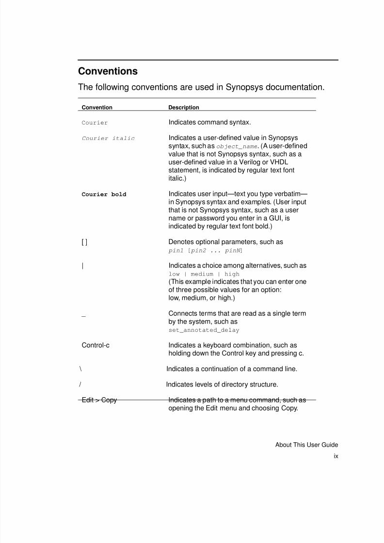
Conventions
The following conventions are used in Synopsys documentation.
Convention Description
Courier Indicates command syntax.
Courier italic Indicates a user-defined value in Synopsyssyntax, such as object_name. (A user-definedvalue that is not Synopsys syntax, such as auser-defined value in a Verilog or VHDLstatement, is indicated by regular text fontitalic.)
Courier bold Indicates user input—text you type verbatim—in Synopsys syntax and examples. (User inputthat is not Synopsys syntax, such as a username or password you enter in a GUI, isindicated by regular text font bold.)
[ ] Denotes optional parameters, such as pin1 [ pin2 ... pinN ]
| Indicates a choice among alternatives, such aslow | medium | high
(This example indicates that you can enter oneof three possible values for an option:low, medium, or high.)
_ Connects terms that are read as a single termby the system, such asset_annotated_delay
Control-c Indicates a keyboard combination, such asholding down the Control key and pressing c.
\ Indicates a continuation of a command line.
/ Indicates levels of directory structure.
Edit > Copy Indicates a path to a menu command, such asopening the Edit menu and choosing Copy.
8/8/2019 Syn Coding
http://slidepdf.com/reader/full/syn-coding 10/84
x
Preface
Customer Support
Customer support is available through SolvNet online customersupport and through contacting the Synopsys Technical Support
Center.
Accessing SolvNet
SolvNet includes an electronic knowledge base of technical articles
and answers to frequently asked questions about Synopsys tools.
SolvNet also gives you access to a wide range of Synopsys online
services including software downloads, documentation on the Web,
and “Enter a Call With the Support Center.”
To access SolvNet,
1. Go to the SolvNet Web page at http://solvnet.synopsys.com.
2. If prompted, enter your user name and password. (If you do not
have a Synopsys user name and password, click New Synopsys
User Registration.)
If you need help using SolvNet, click SolvNet Help in the column on
the left side of the SolvNet Web page.
8/8/2019 Syn Coding
http://slidepdf.com/reader/full/syn-coding 11/84
xi
Customer Support
Contacting the Synopsys Technical Support Center
If you have problems, questions, or suggestions, you can contact the
Synopsys Technical Support Center in the following ways:
• Open a call to your local support center from the Web by going to
http://solvnet.synopsys.com (Synopsys user name and
password required), then clicking “Enter a Call With the Support
Center.”
• Send an e-mail message to [email protected].
• Telephone your local support center.
- Call (800) 245-8005 from within the continental United States.
- Call (650) 584-4200 from Canada.
- Find other local support center telephone numbers at
http://www.synopsys.com/support/support_ctr.

8/8/2019 Syn Coding
http://slidepdf.com/reader/full/syn-coding 12/84
xii
Preface
8/8/2019 Syn Coding
http://slidepdf.com/reader/full/syn-coding 13/84
1-1
1Coding Styles for if Statements and caseStatements 1
This chapter includes a section about the structure implied by simple
if statements and case statements and a section about
more-complex examples that use a combination of if statements and
case statements.
This chapter contains the following sections:
• Basic if and case Statements
• Simple case Statement
8/8/2019 Syn Coding
http://slidepdf.com/reader/full/syn-coding 14/84
1-2
Chapter 1: Coding Styles for if Statements and case Statements
Basic if and case Statements
Examine the following basic if and case statements to understandthe structure they imply and the differences, if any, between the two.
Example 1-1 and Example 1-2 show Verilog and VHDL versions of
four sequential if statements. These designs result in a priority
encoded structure as shown in Figure 1-1.
Example 1-1 Verilog Example of Priority Encoded if Statement
module mult_if(a, b, c, d, sel, z);
input a, b, c, d;
input [3:0] sel;output z;
reg z;
always @(a or b or c or d or sel)
begin
z = 0;
if (sel[0]) z = a;
if (sel[1]) z = b;
if (sel[2]) z = c;
if (sel[3]) z = d;
end
endmodule
Example 1-2 is the equivalent VHDL example.

8/8/2019 Syn Coding
http://slidepdf.com/reader/full/syn-coding 15/84
1-3
Basic if and case Statements
Example 1-2 VHDL Example of Priority Encoded if Statement
library IEEE;
use IEEE.std_logic_1164.all;
entity mult_if is
port (a, b, c, d: in std_logic;
sel: in std_logic_vector(3 downto 0);
z: out std_logic);
end mult_if;
architecture one of mult_if is
begin
process (a, b, c, d, sel)
begin
z <= 0;
if (sel(0) = ’1’) then
z <= a;
end if;
if (sel(1) = ’1’) then
z <= b;
end if;
if (sel(2) = ’1’) then
z <= c;
end if;
if (sel(3) = ’1’) then
z <= d;
end if;
end process;
end one;
Figure 1-1 shows the priority encoded, cascaded structuregenerated for Example 1-1 and Example 1-2.
8/8/2019 Syn Coding
http://slidepdf.com/reader/full/syn-coding 16/84
1-4
Chapter 1: Coding Styles for if Statements and case Statements
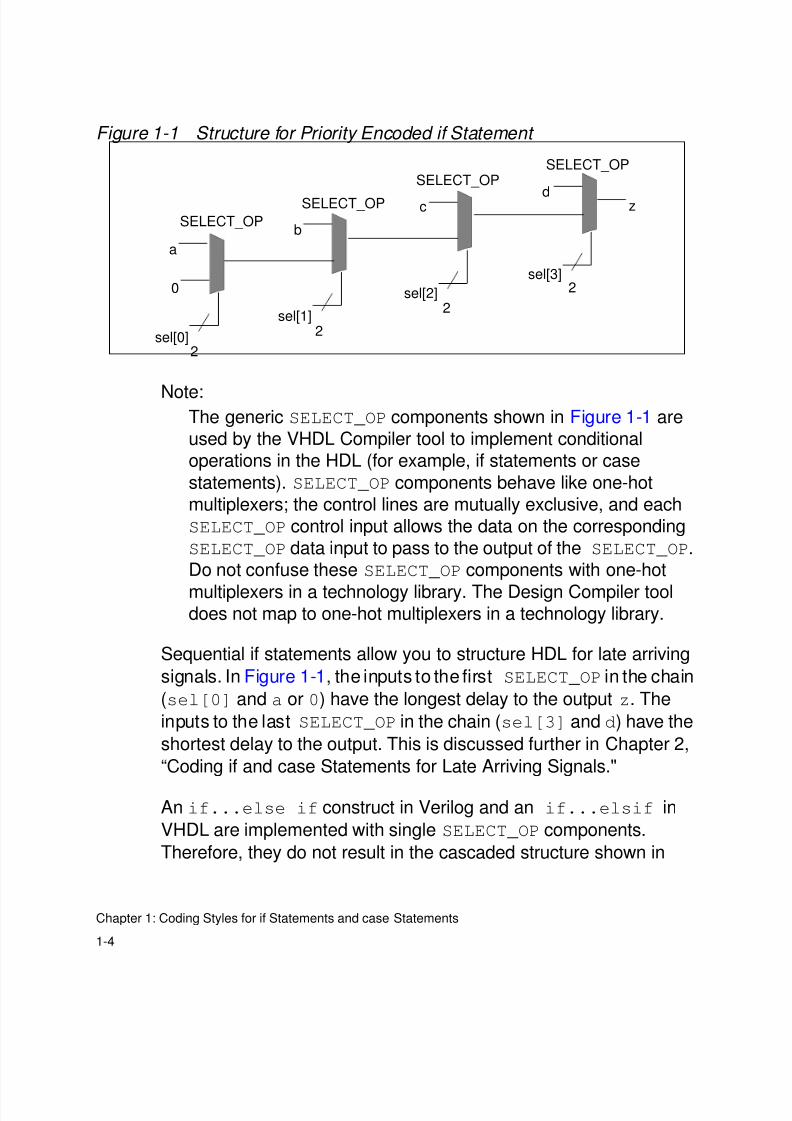
Figure 1-1 Structure for Priority Encoded if Statement
Note:The generic SELECT_OP components shown in Figure 1-1 are
used by the VHDL Compiler tool to implement conditional
operations in the HDL (for example, if statements or case
statements). SELECT_OP components behave like one-hot
multiplexers; the control lines are mutually exclusive, and each
SELECT_OP control input allows the data on the corresponding
SELECT_OP data input to pass to the output of the SELECT_OP.
Do not confuse these SELECT_OP components with one-hot
multiplexers in a technology library. The Design Compiler tooldoes not map to one-hot multiplexers in a technology library.
Sequential if statements allow you to structure HDL for late arriving
signals. In Figure 1-1, the inputs to the first SELECT_OP in the chain
(sel[0] and a or 0) have the longest delay to the output z. The
inputs to the last SELECT_OP in the chain (sel[3] and d) have the
shortest delay to the output. This is discussed further in Chapter 2,
“Coding if and case Statements for Late Arriving Signals."
An if...else if construct in Verilog and an if...elsif in
VHDL are implemented with single SELECT_OP components.
Therefore, they do not result in the cascaded structure shown in
SELECT_OPSELECT_OP
SELECT_OP
SELECT_OPzd
sel[3]
c
2
b
a
0 sel[2]2
sel[1]2sel[0]
2

8/8/2019 Syn Coding
http://slidepdf.com/reader/full/syn-coding 17/84
1-5
Basic if and case Statements
Figure 1-1. Single if statements result in a parallel structure.
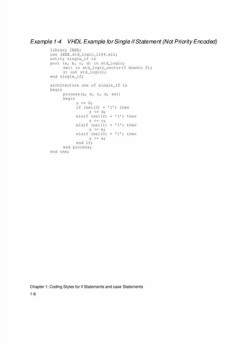
Example 1-3 and Example 1-4 show the Verilog and VHDL
examples that use the single if statement coding style. Figure 1-2
shows the parallel structure inferred for these examples.
Example 1-3 Verilog Example for Single if Statement (Not Priority Encoded)
module single_if(a, b, c, d, sel, z);
input a, b, c, d;
input [3:0] sel;
output z;
reg z;
always @(a or b or c or d or sel)
begin z = 0;
if (sel[3])
z = d;
else if (sel[2])
z = c;
else if (sel[1])
z = b;
else if(sel[0])
z = a;
end
endmodule
8/8/2019 Syn Coding
http://slidepdf.com/reader/full/syn-coding 18/84
1-6
Chapter 1: Coding Styles for if Statements and case Statements
Example 1-4 VHDL Example for Single if Statement (Not Priority Encoded)
library IEEE;
use IEEE.std_logic_1164.all;
entity single_if is
port (a, b, c, d: in std_logic;
sel: in std_logic_vector(3 downto 0);
z: out std_logic);
end single_if;
architecture one of single_if is
begin
process(a, b, c, d, sel)
begin
z <= 0;
if (sel(3) = ’1’) then
z <= d;
elsif (sel(2) = ’1’) then
z <= c;
elsif (sel(1) = ’1’) then
z <= b;
elsif (sel(0) = ’1’) then
z <= a;
end if;
end process;
end one;
8/8/2019 Syn Coding
http://slidepdf.com/reader/full/syn-coding 19/84
1-7
Simple case Statement
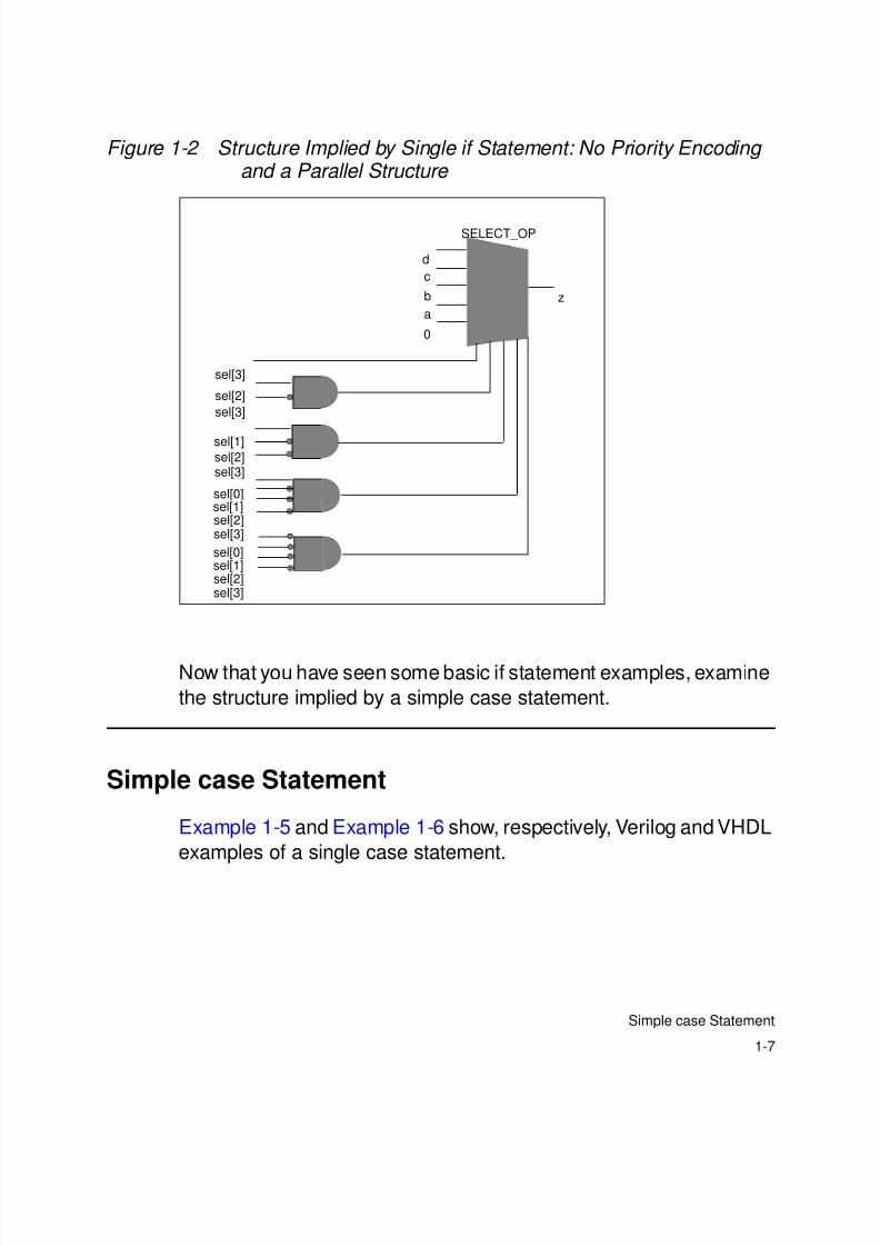
Figure 1-2 Structure Implied by Single if Statement: No Priority Encoding and a Parallel Structure
Now that you have seen some basic if statement examples, examine
the structure implied by a simple case statement.
Simple case Statement
Example 1-5 and Example 1-6 show, respectively, Verilog and VHDL
examples of a single case statement.
SELECT_OP
d
c
b
a
0
z
sel[3]
sel[2]
sel[3]
sel[1]sel[2]sel[3]
sel[0]
sel[1]
sel[2]sel[3]
sel[2]sel[3]
sel[0]sel[1]
8/8/2019 Syn Coding
http://slidepdf.com/reader/full/syn-coding 20/84
1-8
Chapter 1: Coding Styles for if Statements and case Statements
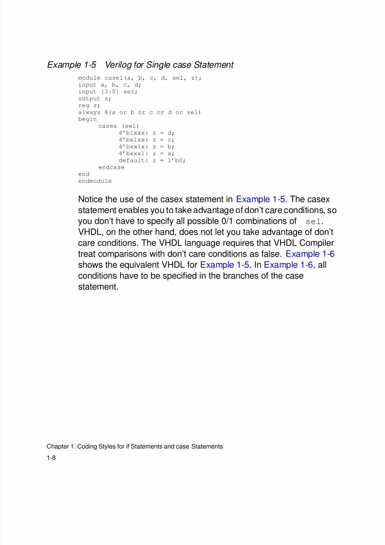
Example 1-5 Verilog for Single case Statement
module case1(a, b, c, d, sel, z);
input a, b, c, d;
input [3:0] sel;
output z;
reg z;
always @(a or b or c or d or sel)
begin
casex (sel)
4’b1xxx: z = d;
4’bx1xx: z = c;
4’bxx1x: z = b;
4’bxxx1: z = a;
default: z = 1’b0;
endcase
end
endmodule
Notice the use of the casex statement in Example 1-5. The casex
statement enables you to take advantage of don’t care conditions, so
you don’t have to specify all possible 0/1 combinations of sel.
VHDL, on the other hand, does not let you take advantage of don’t
care conditions. The VHDL language requires that VHDL Compiler
treat comparisons with don’t care conditions as false. Example 1-6
shows the equivalent VHDL for Example 1-5. In Example 1-6, all
conditions have to be specified in the branches of the case
statement.
8/8/2019 Syn Coding
http://slidepdf.com/reader/full/syn-coding 21/84
1-9
Simple case Statement
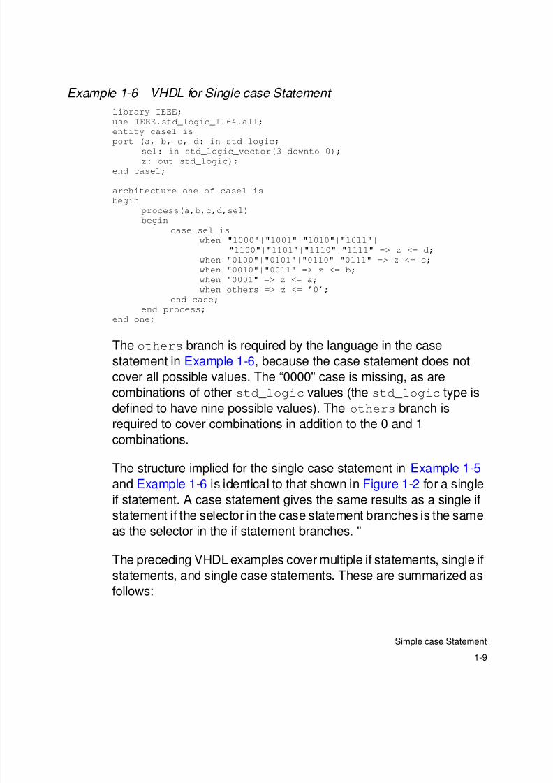
Example 1-6 VHDL for Single case Statement
library IEEE;
use IEEE.std_logic_1164.all;
entity case1 is
port (a, b, c, d: in std_logic;
sel: in std_logic_vector(3 downto 0);
z: out std_logic);
end case1;
architecture one of case1 is
begin
process(a,b,c,d,sel)
begin
case sel is
when "1000"|"1001"|"1010"|"1011"|
"1100"|"1101"|"1110"|"1111" => z <= d;
when "0100"|"0101"|"0110"|"0111" => z <= c;
when "0010"|"0011" => z <= b;
when "0001" => z <= a;
when others => z <= ’0’;
end case;
end process;
end one;
The others branch is required by the language in the case
statement in Example 1-6, because the case statement does not
cover all possible values. The “0000" case is missing, as are
combinations of other std_logic values (the std_logic type is
defined to have nine possible values). The others branch isrequired to cover combinations in addition to the 0 and 1
combinations.
The structure implied for the single case statement in Example 1-5
and Example 1-6 is identical to that shown in Figure 1-2 for a single
if statement. A case statement gives the same results as a single if
statement if the selector in the case statement branches is the same
as the selector in the if statement branches. "
The preceding VHDL examples cover multiple if statements, single if
statements, and single case statements. These are summarized as
follows:

8/8/2019 Syn Coding
http://slidepdf.com/reader/full/syn-coding 22/84
1-10
Chapter 1: Coding Styles for if Statements and case Statements
Multiple if
statement4;
if (cond = cond1) then
statement1;
end if;
if (cond = cond2) then
statement2;
end if;
if (cond = cond3) then
statement3;
end if;
A multiple if statement style has the longest path. Both the data and
the control signals cascade through multipleSELECT_OP constructs.
Single ifif (cond = cond1) then
statement1;
elsif (cond = cond2) then
statement2;
elsif (cond = cond3) then
statement3;
else
statement4;
end if;
A single if statement is represented by a single SELECT_OP, but the
control signals are priority encoded. The delay through theSELECT_OP is the same for all the data inputs.
Single case
case (cond) is
when cond1 =>
statement1;
when cond2 =>
statement2;
when cond3 =>
statement3;
when others =>
statement4;end case;
8/8/2019 Syn Coding
http://slidepdf.com/reader/full/syn-coding 23/84
1-11
Simple case Statement
A single case statement is also represented by a singleSELECT_OP.
There is no priority encoding for the control signals. The delay
through the SELECT_OP is the same for all the data inputs. A single
if and a single case statement give identical results if the selector isthe same in every branch of the if statement.

8/8/2019 Syn Coding
http://slidepdf.com/reader/full/syn-coding 24/84
1-12
Chapter 1: Coding Styles for if Statements and case Statements

8/8/2019 Syn Coding
http://slidepdf.com/reader/full/syn-coding 25/84
2-1
2Coding if and case Statements for LateArriving Signals 2
Designers usually know which signals in a design are late arriving
signals. This knowledge can be used to structure HDL so that the
late arriving signals appear closer to the output. This chapter gives
examples of restructuring if and case statements for late arriving
signals.
This chapter contains the following sections:
• Sequential if Statements: Late Arriving Data Signal
• Single if Statement: Late Arriving Control Signal
• if Statement With Nested case Statement: Late Arriving DataSignal
• case Statement With Nested if Statement: Late Arriving Control
Signal
8/8/2019 Syn Coding
http://slidepdf.com/reader/full/syn-coding 26/84
2-2
Chapter 2: Coding if and case Statements for Late Arriving Signals
Sequential if Statements: Late Arriving Data Signal
Sequential if statements allow you to structure your HDL based oncritical signals. You may want to use sequential if statements, as
shown in Example 1-1 on page 1-2 and Example 1-2 on page 1-3, if
the input d in those examples is a late arriving signal. Figure 1-1 on
page 1-4 shows that d is an input to the last SELECT_OP in the chain.
Therefore, d is as close to the output as possible.
However, if b is a late arriving signal, Example 1-1 on page 1-2 and
Example 1-2 on page 1-3 do not show the optimal coding style.
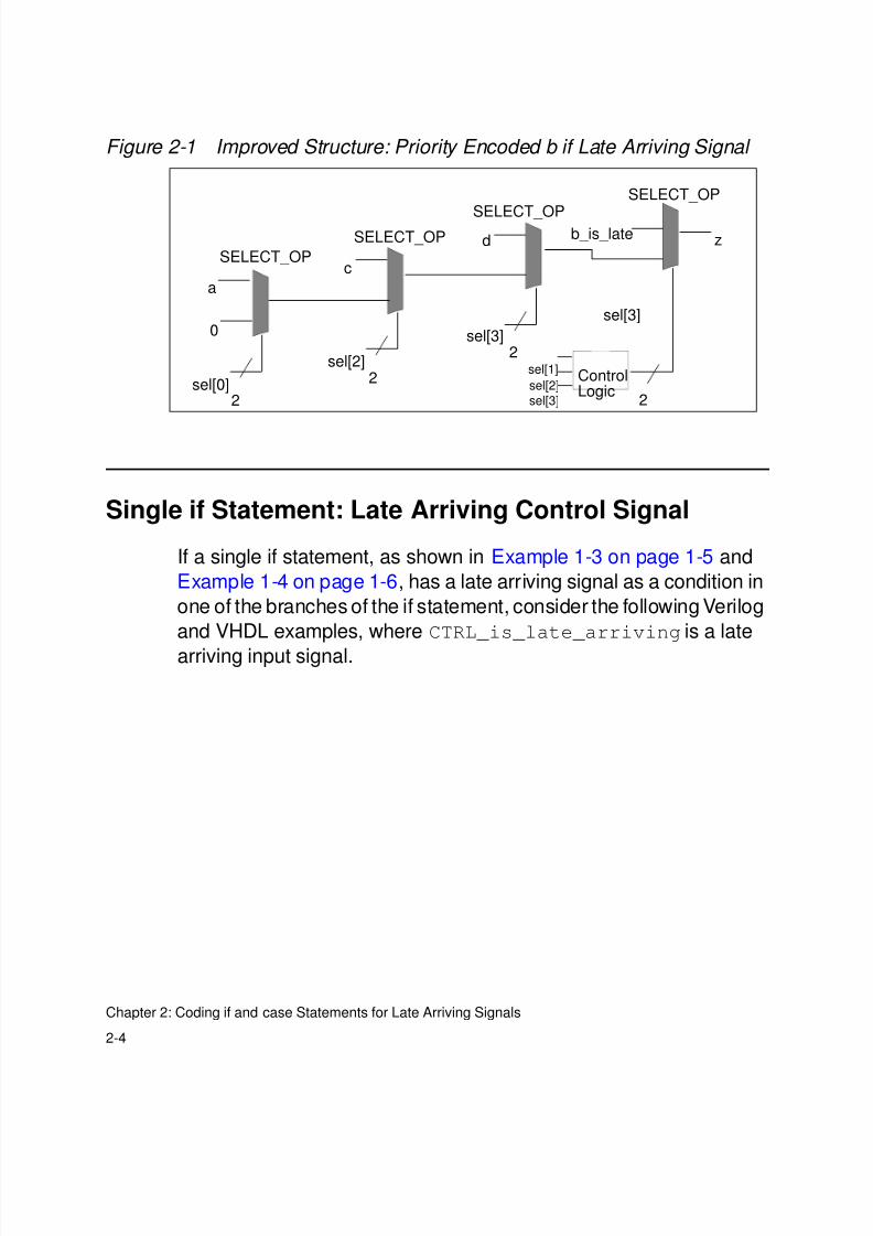
When b is the late arriving signal, the optimal coding style involvesrestructuring the HDL as shown in Example 2-1 and Example 2-2.
This restructuring moves b (b_is_late in Example 2-1 and
Example 2-2) closer to the output z.
Example 2-1 Improved Verilog for Priority Encoded if
module mult_if_improved(a, b_is_late, c, d, sel, z);
input a, b_is_late, c, d;
input [3:0] sel;
output z;
reg z, z1;
always @(a or b_is_late or c or d or sel)
begin
z1 = 0;
if (sel[0])
z1 = a;
if (sel[2])
z1 = c;
if (sel[3])
z1 = d;
if (sel[1] & ~(sel[2]|sel[3]))
z = b_is_late;
else
z = z1;
end
endmodule
Example 2-2 is the equivalent VHDL example.
8/8/2019 Syn Coding
http://slidepdf.com/reader/full/syn-coding 27/84
8/8/2019 Syn Coding
http://slidepdf.com/reader/full/syn-coding 28/84
2-4
Chapter 2: Coding if and case Statements for Late Arriving Signals
Figure 2-1 Improved Structure: Priority Encoded b if Late Arriving Signal
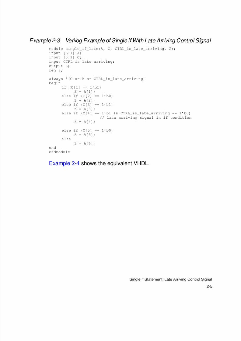
Single if Statement: Late Arriving Control Signal
If a single if statement, as shown in Example 1-3 on page 1-5 and
Example 1-4 on page 1-6, has a late arriving signal as a condition in
one of the branches of the if statement, consider the following Verilog
and VHDL examples, where CTRL_is_late_arriving is a late
arriving input signal.
SELECT_OP
SELECT_OPSELECT_OP
SELECT_OPzd
sel[3]
c
b_is_late
a
0 sel[3]2
sel[2]2sel[0]
2sel[2]
sel[1]
sel[3]
ControlLogic
2
8/8/2019 Syn Coding
http://slidepdf.com/reader/full/syn-coding 29/84
2-5
Single if Statement: Late Arriving Control Signal
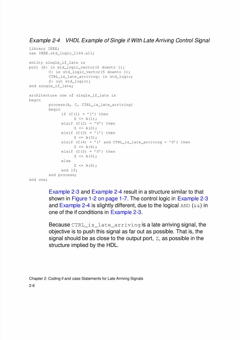
Example 2-3 Verilog Example of Single if With Late Arriving Control Signal
module single_if_late(A, C, CTRL_is_late_arriving, Z);
input [6:1] A;
input [5:1] C;
input CTRL_is_late_arriving;
output Z;
reg Z;
always @(C or A or CTRL_is_late_arriving)
begin
if (C[1] == 1’b1)
Z = A[1];
else if (C[2] == 1’b0)
Z = A[2];
else if (C[3] == 1’b1)
Z = A[3];
else if (C[4] == 1’b1 && CTRL_is_late_arriving == 1’b0)
// late arriving signal in if condition
Z = A[4];
else if (C[5] == 1’b0)
Z = A[5];
else
Z = A[6];
end
endmodule
Example 2-4 shows the equivalent VHDL.
8/8/2019 Syn Coding
http://slidepdf.com/reader/full/syn-coding 30/84
2-6
Chapter 2: Coding if and case Statements for Late Arriving Signals
Example 2-4 VHDL Example of Single if With Late Arriving Control Signal
library IEEE;
use IEEE.std_logic_1164.all;
entity single_if_late is
port (A: in std_logic_vector(6 downto 1);
C: in std_logic_vector(5 downto 1);
CTRL_is_late_arriving: in std_logic;
Z: out std_logic);
end single_if_late;
architecture one of single_if_late is
begin
process(A, C, CTRL_is_late_arriving)
begin
if (C(1) = ’1’) then
Z <= A(1);elsif (C(2) = ’0’) then
Z <= A(2);
elsif (C(3) = ’1’) then
Z <= A(3);
elsif (C(4) = ’1’ and CTRL_is_late_arriving = ’0’) then
Z <= A(4);
elsif (C(5) = ’0’) then
Z <= A(5);
else
Z <= A(6);
end if;
end process;
end one;
Example 2-3 and Example 2-4 result in a structure similar to that
shown in Figure 1-2 on page 1-7. The control logic in Example 2-3
and Example 2-4 is slightly different, due to the logical AND (&&) in
one of the if conditions in Example 2-3.
Because CTRL_is_late_arriving is a late arriving signal, the
objective is to push this signal as far out as possible. That is, the
signal should be as close to the output port, Z, as possible in thestructure implied by the HDL.

8/8/2019 Syn Coding
http://slidepdf.com/reader/full/syn-coding 31/84
2-7
Single if Statement: Late Arriving Control Signal
Example 2-5 and Example 2-6 show the modified Verilog and VHDL
that achieve this objective. The signal CTRL_is_late_arriving
is pulled out of the if...else if statement and is thereby pushed
closer to the output.
Example 2-5 Improved Verilog for Single if With Late Arriving Control Signal
module single_if_improved(A, C, CTRL_is_late_arriving, Z);
input [6:1] A;
input [5:1] C;
input CTRL_is_late_arriving;
output Z;
reg Z;
reg Z1;
wire Z2, prev_cond;
always @(A or C)begin
if (C[1] == 1’b1)
Z1 = A[1];
else if (C[2] == 1’b0)
Z1 = A[2];
else if (C[3] == 1’b1)
Z1 = A[3];
else if (C[5] == 1’b0)// removed the branch with the
Z1 = A[5]; //late-arriving control signal
else
Z1 = A[6];
end
assign Z2 = A[4];
assign prev_cond = (C[1] == 1’b1) || (C[2] == 1’b0) || (C[3] == 1’b1);
always @(C or prev_cond or CTRL_is_late_arriving or Z1 or Z2)
begin
if (C[4] == 1’b1 && CTRL_is_late_arriving == 1’b0)
if (prev_cond)
Z = Z1;
else
Z = Z2;
else
Z = Z1;
end
endmodule
Example 2-6 shows the equivalent improved VHDL.
8/8/2019 Syn Coding
http://slidepdf.com/reader/full/syn-coding 32/84
2-8
Chapter 2: Coding if and case Statements for Late Arriving Signals
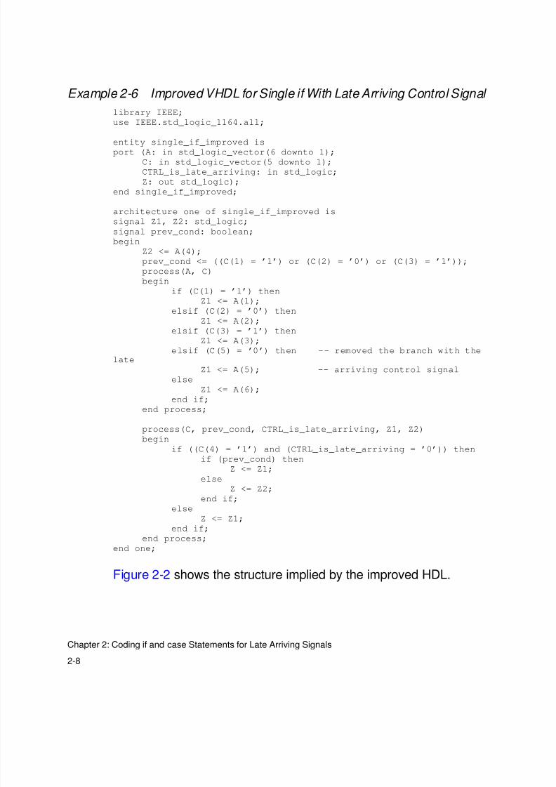
Example 2-6 Improved VHDL for Single if With Late Arriving Control Signal
library IEEE;
use IEEE.std_logic_1164.all;
entity single_if_improved is
port (A: in std_logic_vector(6 downto 1);
C: in std_logic_vector(5 downto 1);
CTRL_is_late_arriving: in std_logic;
Z: out std_logic);
end single_if_improved;
architecture one of single_if_improved is
signal Z1, Z2: std_logic;
signal prev_cond: boolean;
begin
Z2 <= A(4);
prev_cond <= ((C(1) = ’1’) or (C(2) = ’0’) or (C(3) = ’1’));
process(A, C)
begin
if (C(1) = ’1’) then
Z1 <= A(1);
elsif (C(2) = ’0’) then
Z1 <= A(2);
elsif (C(3) = ’1’) then
Z1 <= A(3);
elsif (C(5) = ’0’) then -- removed the branch with thelate
Z1 <= A(5); -- arriving control signal
else
Z1 <= A(6);
end if;
end process;
process(C, prev_cond, CTRL_is_late_arriving, Z1, Z2)
begin
if ((C(4) = ’1’) and (CTRL_is_late_arriving = ’0’)) then
if (prev_cond) then
Z <= Z1;
else
Z <= Z2;
end if;
else
Z <= Z1;
end if;
end process;
end one;
Figure 2-2 shows the structure implied by the improved HDL.
8/8/2019 Syn Coding
http://slidepdf.com/reader/full/syn-coding 33/84
2-9
if Statement With Nested case Statement: Late Arriving Data Signal
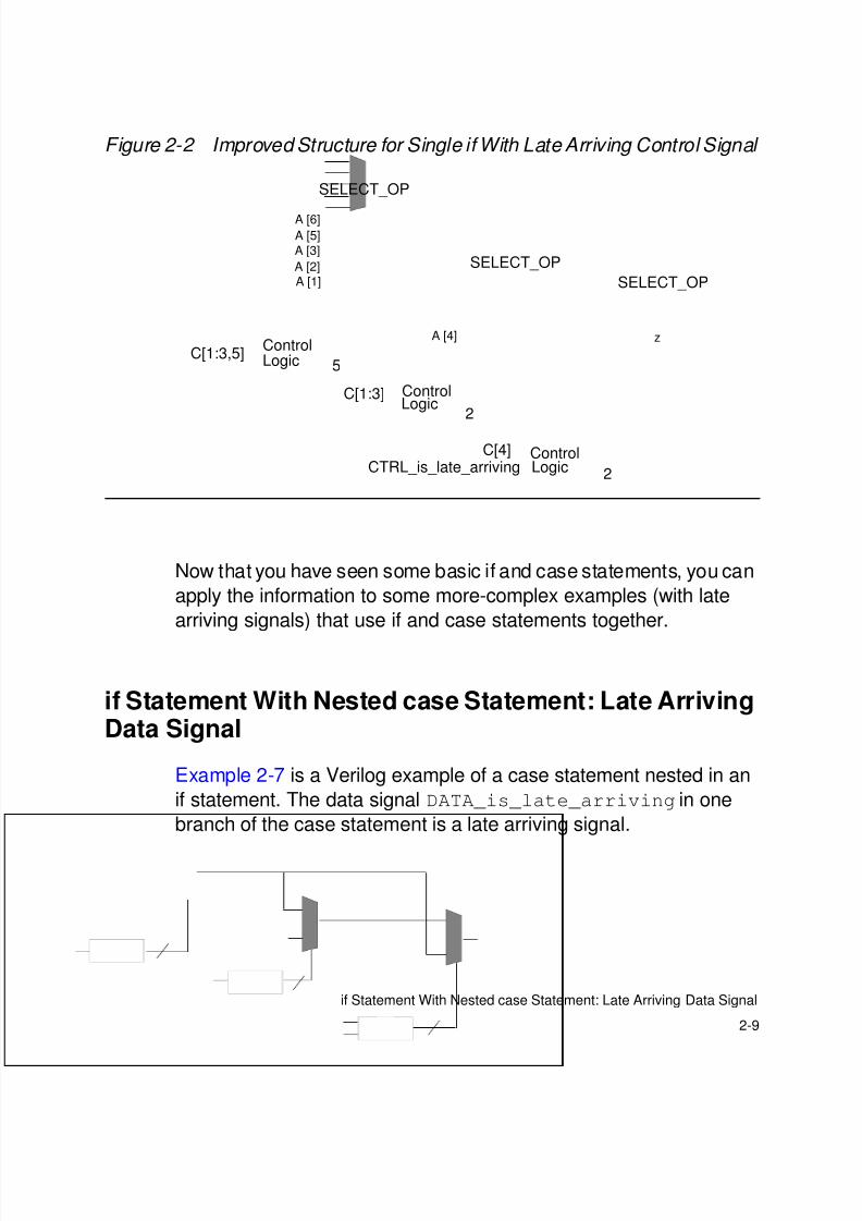
Figure 2-2 Improved Structure for Single if With Late Arriving Control Signal
Now that you have seen some basic if and case statements, you can
apply the information to some more-complex examples (with late
arriving signals) that use if and case statements together.
if Statement With Nested case Statement: Late ArrivingData Signal
Example 2-7 is a Verilog example of a case statement nested in an
if statement. The data signal DATA_is_late_arriving in one
branch of the case statement is a late arriving signal.
A [6]
A [5]
A [3]
A [2]A [1]
SELECT_OP
ControlLogic 5
C[1:3,5]
SELECT_OP
SELECT_OP
A [4] z
LogicControlC[1:3]
2
LogicControlC[4]
CTRL_is_late_arriving 2
8/8/2019 Syn Coding
http://slidepdf.com/reader/full/syn-coding 34/84
2-10
Chapter 2: Coding if and case Statements for Late Arriving Signals
Example 2-7 Original Verilog for case Statement in if Statement
module case_in_if_01(A, DATA_is_late_arriving, C, sel, Z);
input [8:1] A;
input DATA_is_late_arriving;
input [2:0] sel;
input [5:1] C;
output Z;
reg Z;
always @ (sel or C or A or DATA_is_late_arriving)
begin
if (C[1])
Z = A[5];
else if (C[2] == 1’b0)
Z = A[4];
else if (C[3])
Z = A[1];
else if (C[4])
case (sel)
3’b010: Z = A[8];
3’b011: Z = DATA_is_late_arriving;
3’b101: Z = A[7];
3’b110: Z = A[6];
default: Z = A[2];
endcase
else if (C[5] == 1’b0)
Z = A[2];
else
Z = A[3];
end
endmodule
Example 2-8 is the VHDL equivalent of Example 2-7.
8/8/2019 Syn Coding
http://slidepdf.com/reader/full/syn-coding 35/84
2-11
if Statement With Nested case Statement: Late Arriving Data Signal
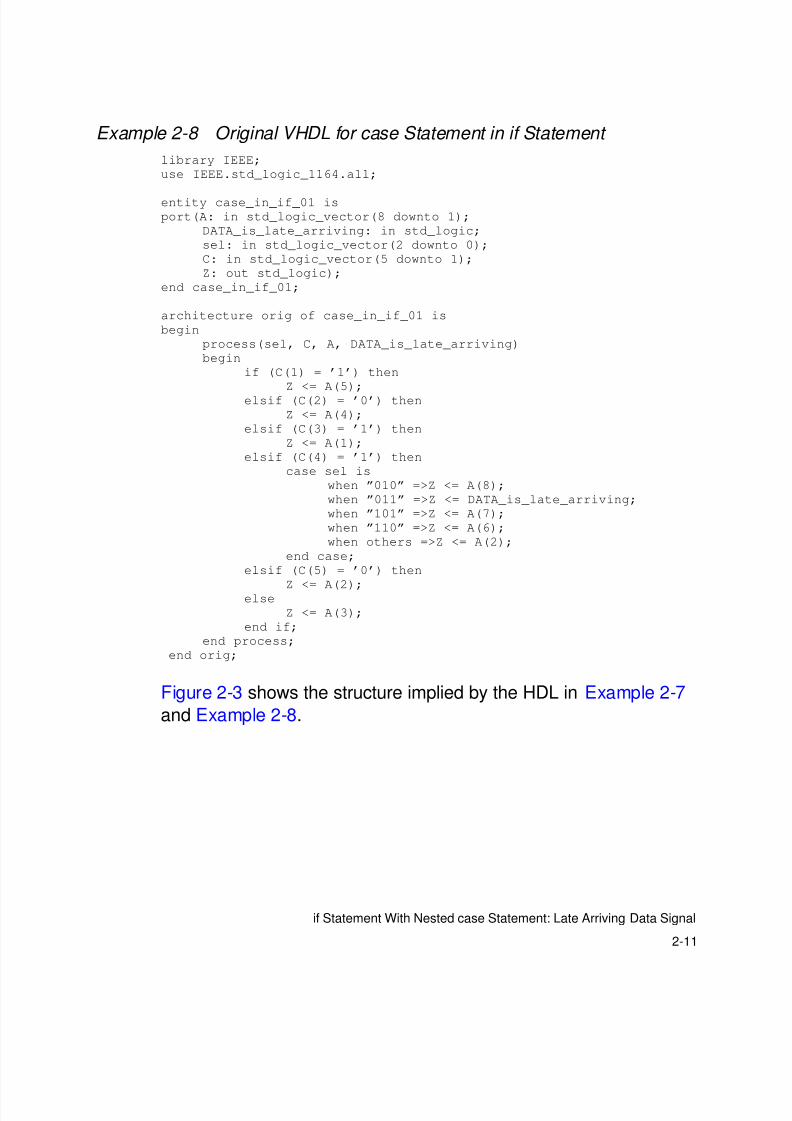
Example 2-8 Original VHDL for case Statement in if Statement
library IEEE;
use IEEE.std_logic_1164.all;
entity case_in_if_01 is
port(A: in std_logic_vector(8 downto 1);
DATA_is_late_arriving: in std_logic;
sel: in std_logic_vector(2 downto 0);
C: in std_logic_vector(5 downto 1);
Z: out std_logic);
end case_in_if_01;
architecture orig of case_in_if_01 is
begin
process(sel, C, A, DATA_is_late_arriving)
begin
if (C(1) = ’1’) then
Z <= A(5);
elsif (C(2) = ’0’) then
Z <= A(4);
elsif (C(3) = ’1’) then
Z <= A(1);
elsif (C(4) = ’1’) then
case sel is
when ”010” =>Z <= A(8);
when ”011” =>Z <= DATA_is_late_arriving;
when ”101” =>Z <= A(7);
when ”110” =>Z <= A(6);
when others =>Z <= A(2);
end case;
elsif (C(5) = ’0’) then
Z <= A(2);else
Z <= A(3);
end if;
end process;
end orig;
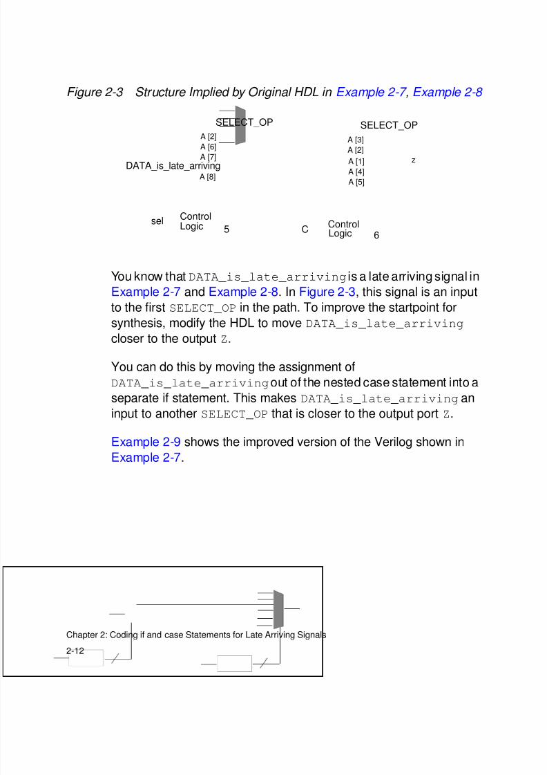
Figure 2-3 shows the structure implied by the HDL in Example 2-7
and Example 2-8.
8/8/2019 Syn Coding
http://slidepdf.com/reader/full/syn-coding 36/84
8/8/2019 Syn Coding
http://slidepdf.com/reader/full/syn-coding 37/84
2-13
if Statement With Nested case Statement: Late Arriving Data Signal
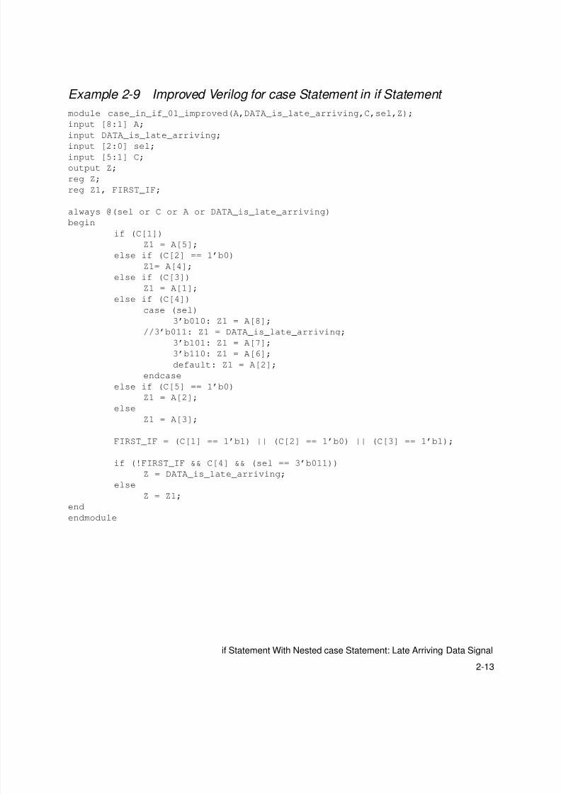
Example 2-9 Improved Verilog for case Statement in if Statement
module case_in_if_01_improved(A,DATA_is_late_arriving,C,sel,Z);
input [8:1] A;
input DATA_is_late_arriving;input [2:0] sel;
input [5:1] C;
output Z;
reg Z;
reg Z1, FIRST_IF;
always @(sel or C or A or DATA_is_late_arriving)
begin
if (C[1])
Z1 = A[5];
else if (C[2] == 1’b0)
Z1= A[4];
else if (C[3])Z1 = A[1];
else if (C[4])
case (sel)
3’b010: Z1 = A[8];
//3’b011: Z1 = DATA_is_late_arriving;
3’b101: Z1 = A[7];
3’b110: Z1 = A[6];
default: Z1 = A[2];
endcase
else if (C[5] == 1’b0)
Z1 = A[2];
else
Z1 = A[3];
FIRST_IF = (C[1] == 1’b1) || (C[2] == 1’b0) || (C[3] == 1’b1);
if (!FIRST_IF && C[4] && (sel == 3’b011))
Z = DATA_is_late_arriving;
else
Z = Z1;
end
endmodule
8/8/2019 Syn Coding
http://slidepdf.com/reader/full/syn-coding 38/84

8/8/2019 Syn Coding
http://slidepdf.com/reader/full/syn-coding 39/84
2-15
case Statement With Nested if Statement: Late Arriving Control Signal
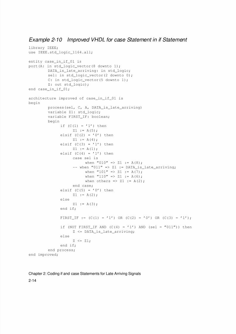
Example 2-10 is an improved version of the VHDL shown in
Example 2-8.
The structure implied by the modified HDL in Example 2-9 andExample 2-10 is given in Figure 2-4.
Figure 2-4 Structure Implied by Improved HDL in Example 2-9 ,Example 2-10
case Statement With Nested if Statement: Late ArrivingControl Signal
Example 2-11 and Example 2-12 show Verilog and VHDL for an if
statement nested in a case statement. These examples assume
sel[1] is a late arriving signal.
A [2]
A [6]
A [7]A [0]
SELECT_OP
ControlLogic 4
DATA_is_late_arriving
sel [2:0]
A [3]
A [2]
A [1]
A [4]
A [5]
SELECT_OP
6LogicControl
C [5:1]
z
SELECT_OP
2ControlLogic
sel [2:0]C [4:1]
8/8/2019 Syn Coding
http://slidepdf.com/reader/full/syn-coding 40/84
2-16
Chapter 2: Coding if and case Statements for Late Arriving Signals
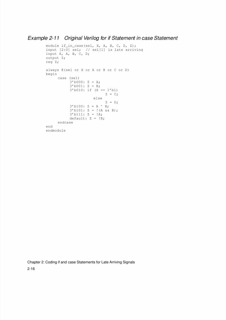
Example 2-11 Original Verilog for if Statement in case Statement
module if_in_case(sel, X, A, B, C, D, Z);
input [2:0] sel; // sel[1] is late arriving
input X, A, B, C, D;
output Z;
reg Z;
always @(sel or X or A or B or C or D)
begin
case (sel)
3’b000: Z = A;
3’b001: Z = B;
3’b010: if (X == 1’b1)
Z = C;
else
Z = D;
3’b100: Z = A ^ B;
3’b101: Z = !(A && B);
3’b111: Z = !A;
default: Z = !B;
endcase
end
endmodule
8/8/2019 Syn Coding
http://slidepdf.com/reader/full/syn-coding 41/84
2-17
case Statement With Nested if Statement: Late Arriving Control Signal
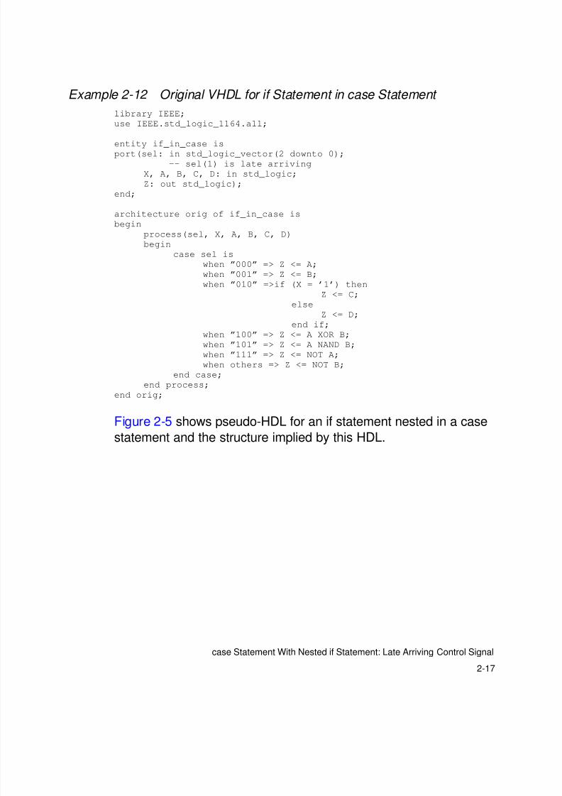
Example 2-12 Original VHDL for if Statement in case Statement
library IEEE;
use IEEE.std_logic_1164.all;
entity if_in_case is
port(sel: in std_logic_vector(2 downto 0);
-- sel(1) is late arriving
X, A, B, C, D: in std_logic;
Z: out std_logic);
end;
architecture orig of if_in_case is
begin
process(sel, X, A, B, C, D)
begin
case sel is
when ”000” => Z <= A;
when ”001” => Z <= B;
when ”010” =>if (X = ’1’) then
Z <= C;
else
Z <= D;
end if;
when ”100” => Z <= A XOR B;
when ”101” => Z <= A NAND B;
when ”111” => Z <= NOT A;
when others => Z <= NOT B;
end case;
end process;
end orig;
Figure 2-5 shows pseudo-HDL for an if statement nested in a casestatement and the structure implied by this HDL.
8/8/2019 Syn Coding
http://slidepdf.com/reader/full/syn-coding 42/84
2-18
Chapter 2: Coding if and case Statements for Late Arriving Signals
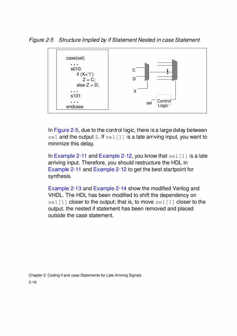
Figure 2-5 Structure Implied by if Statement Nested in case Statement
In Figure 2-5, due to the control logic, there is a large delay between
sel and the output Z. If sel[1] is a late arriving input, you want to
minimize this delay.
In Example 2-11 and Example 2-12, you know that sel[1] is a late
arriving input. Therefore, you should restructure the HDL in
Example 2-11 and Example 2-12 to get the best startpoint for
synthesis.
Example 2-13 and Example 2-14 show the modified Verilog and
VHDL. The HDL has been modified to shift the dependency on
sel[1] closer to the output; that is, to move sel[1] closer to the
output, the nested if statement has been removed and placed
outside the case statement.
case(sel). . .s010;
if (X=’1’)Z = C;
else Z = D;. . .s101;. . .
endcase
Control
C
D
X
...
selLogic
8/8/2019 Syn Coding
http://slidepdf.com/reader/full/syn-coding 43/84
2-19
case Statement With Nested if Statement: Late Arriving Control Signal
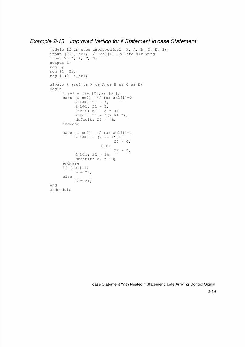
Example 2-13 Improved Verilog for if Statement in case Statement
module if_in_case_improved(sel, X, A, B, C, D, Z);
input [2:0] sel; // sel[1] is late arriving
input X, A, B, C, D;
output Z;
reg Z;
reg Z1, Z2;
reg [1:0] i_sel;
always @ (sel or X or A or B or C or D)
begin
i_sel = {sel[2],sel[0]};
case (i_sel) // for sel[1]=0
2’b00: Z1 = A;
2’b01: Z1 = B;
2’b10: Z1 = A ^ B;
2’b11: Z1 = !(A && B);
default: Z1 = !B;
endcase
case (i_sel) // for sel[1]=1
2’b00:if (X == 1’b1)
Z2 = C;
else
Z2 = D;
2’b11: Z2 = !A;
default: Z2 = !B;
endcase
if (sel[1])
Z = Z2;
else
Z = Z1;end
endmodule
8/8/2019 Syn Coding
http://slidepdf.com/reader/full/syn-coding 44/84
2-20
Chapter 2: Coding if and case Statements for Late Arriving Signals
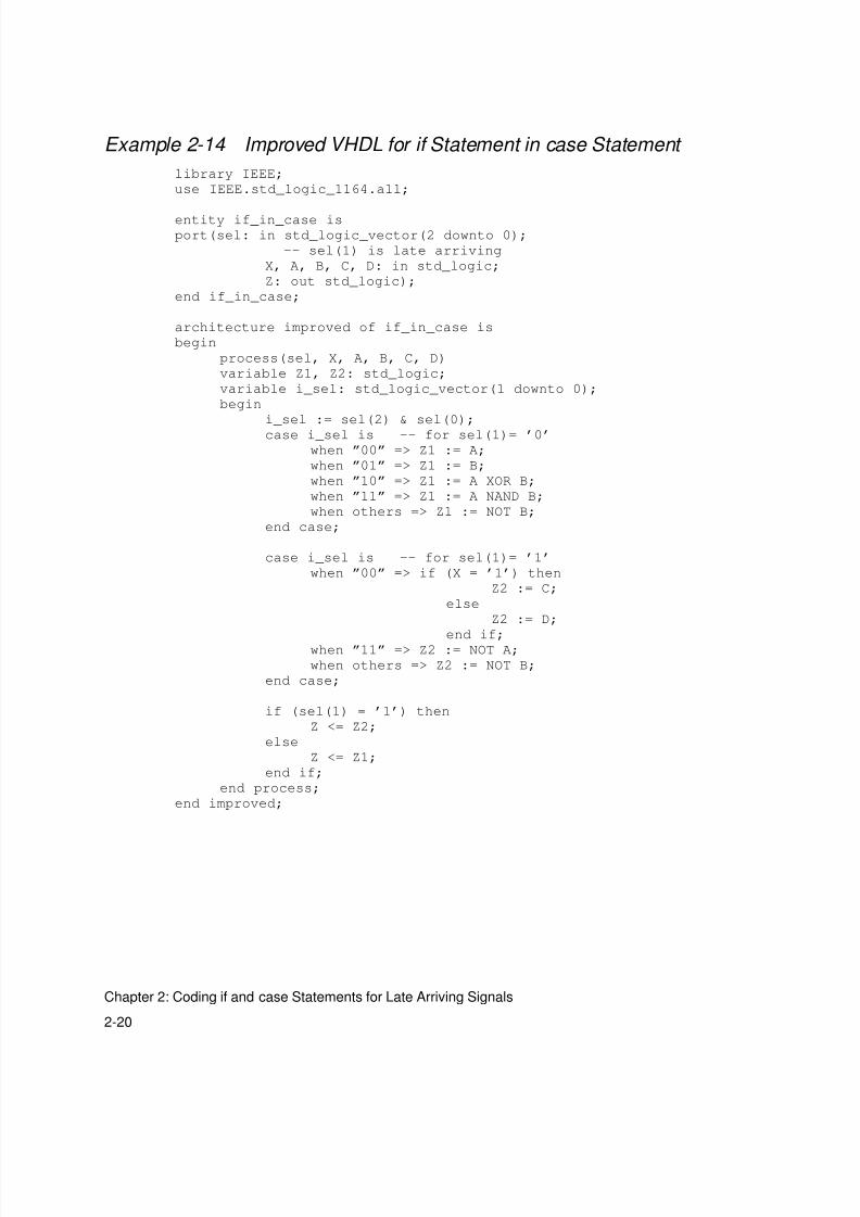
Example 2-14 Improved VHDL for if Statement in case Statement
library IEEE;
use IEEE.std_logic_1164.all;
entity if_in_case is
port(sel: in std_logic_vector(2 downto 0);
-- sel(1) is late arriving
X, A, B, C, D: in std_logic;
Z: out std_logic);
end if_in_case;
architecture improved of if_in_case is
begin
process(sel, X, A, B, C, D)
variable Z1, Z2: std_logic;
variable i_sel: std_logic_vector(1 downto 0);
begin
i_sel := sel(2) & sel(0);
case i_sel is -- for sel(1)= ’0’
when ”00” => Z1 := A;
when ”01” => Z1 := B;
when ”10” => Z1 := A XOR B;
when ”11” => Z1 := A NAND B;
when others => Z1 := NOT B;
end case;
case i_sel is -- for sel(1)= ’1’
when ”00” => if (X = ’1’) then
Z2 := C;
else
Z2 := D;
end if;when ”11” => Z2 := NOT A;
when others => Z2 := NOT B;
end case;
if (sel(1) = ’1’) then
Z <= Z2;
else
Z <= Z1;
end if;
end process;
end improved;
8/8/2019 Syn Coding
http://slidepdf.com/reader/full/syn-coding 45/84
2-21
case Statement With Nested if Statement: Late Arriving Control Signal
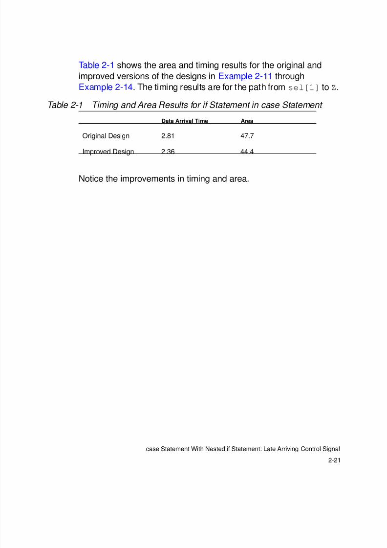
Table 2-1 shows the area and timing results for the original and
improved versions of the designs in Example 2-11 through
Example 2-14. The timing results are for the path from sel[1] to Z.
Notice the improvements in timing and area.
Table 2-1 Timing and Area Results for if Statement in case Statement
Data Arrival Time Area
Original Design 2.81 47.7
Improved Design 2.36 44.4

8/8/2019 Syn Coding
http://slidepdf.com/reader/full/syn-coding 46/84
2-22
Chapter 2: Coding if and case Statements for Late Arriving Signals
8/8/2019 Syn Coding
http://slidepdf.com/reader/full/syn-coding 47/84
3-1
3Coding Styles for Logic Building Blocks 3
This chapter shows different coding styles for logic building blocks
such as decoders and priority encoders. A typical coding style and a
recommended coding style are presented for each building block.
The examples in this chapter are parameterizable: They can bemodified for any bit-width. Therefore, they may appearmore complex
than examples written for a specific bit-width.
This chapter contains the following sections:
• Decoder
• Priority Encoder
• Reduction XOR
8/8/2019 Syn Coding
http://slidepdf.com/reader/full/syn-coding 48/84
3-2
Chapter 3: Coding Styles for Logic Building Blocks
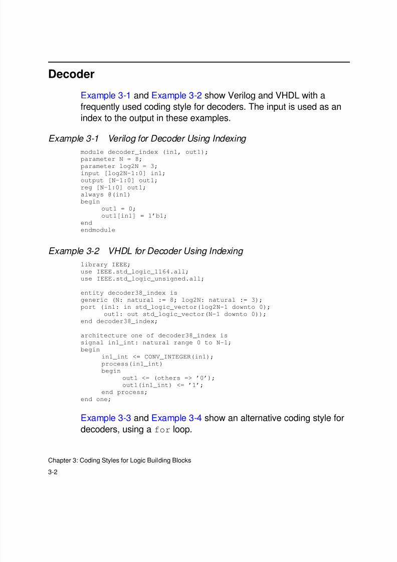
Decoder
Example 3-1 and Example 3-2 show Verilog and VHDL with afrequently used coding style for decoders. The input is used as an
index to the output in these examples.
Example 3-1 Verilog for Decoder Using Indexing
module decoder_index (in1, out1);
parameter N = 8;
parameter log2N = 3;
input [log2N-1:0] in1;
output [N-1:0] out1;
reg [N-1:0] out1;
always @(in1)begin
out1 = 0;
out1[in1] = 1’b1;
end
endmodule
Example 3-2 VHDL for Decoder Using Indexing
library IEEE;
use IEEE.std_logic_1164.all;
use IEEE.std_logic_unsigned.all;
entity decoder38_index isgeneric (N: natural := 8; log2N: natural := 3);
port (in1: in std_logic_vector(log2N-1 downto 0);
out1: out std_logic_vector(N-1 downto 0));
end decoder38_index;
architecture one of decoder38_index is
signal in1_int: natural range 0 to N-1;
begin
in1_int <= CONV_INTEGER(in1);
process(in1_int)
begin
out1 <= (others => ’0’);
out1(in1_int) <= ’1’;
end process;end one;
Example 3-3 and Example 3-4 show an alternative coding style for
decoders, using a for loop.
8/8/2019 Syn Coding
http://slidepdf.com/reader/full/syn-coding 49/84
3-3
Decoder
Example 3-3 Verilog for Decoder Using Loop
module decoder38_loop (in1, out1);
parameter N = 8;
parameter log2N = 3;
input [log2N-1:0] in1;
output [N-1:0] out1;
reg [N-1:0] out1;
integer i;
always @(in1)
begin
for(i=0;i<N;i=i+1)
out1[i] = (in1 == i);
end
endmodule
Example 3-4 VHDL for Decoder Using Loop
library IEEE;
use IEEE.std_logic_1164.all;
use IEEE.std_logic_unsigned.all;
entity decoder_loop is
generic (N: natural := 8; log2N: natural := 3);
port (in1: in std_logic_vector(log2N-1 downto 0);
out1: out std_logic_vector(N-1 downto 0));
end decoder_loop;
architecture one of decoder_loop is
signal in1_int: natural range 0 to N-1;
begin
in1_int <= CONV_INTEGER(in1);
process(in1_int)
begin
out1 <= (others => ’0’);
for i in 0 to N-1 loop
if (in1_int = i) then
out1(i) <= ’1’;
end if;
end loop;
end process;
end one;
8/8/2019 Syn Coding
http://slidepdf.com/reader/full/syn-coding 50/84
3-4
Chapter 3: Coding Styles for Logic Building Blocks
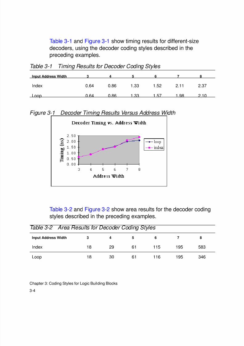
Table 3-1 and Figure 3-1 show timing results for different-size
decoders, using the decoder coding styles described in the
preceding examples.
Figure 3-1 Decoder Timing Results Versus Address Width
Table 3-2 and Figure 3-2 show area results for the decoder coding
styles described in the preceding examples.
Table 3-1 Timing Results for Decoder Coding Styles
Input Address Width 3 4 5 6 7 8
Index 0.64 0.86 1.33 1.52 2.11 2.37
Loop 0.64 0.86 1.33 1.57 1.98 2.10
Table 3-2 Area Results for Decoder Coding Styles
Input Address Width 3 4 5 6 7 8
Index 18 29 61 115 195 583
Loop 18 30 61 116 195 346

8/8/2019 Syn Coding
http://slidepdf.com/reader/full/syn-coding 51/84
3-5
Decoder
Figure 3-2 Decoder Area Versus Address Width
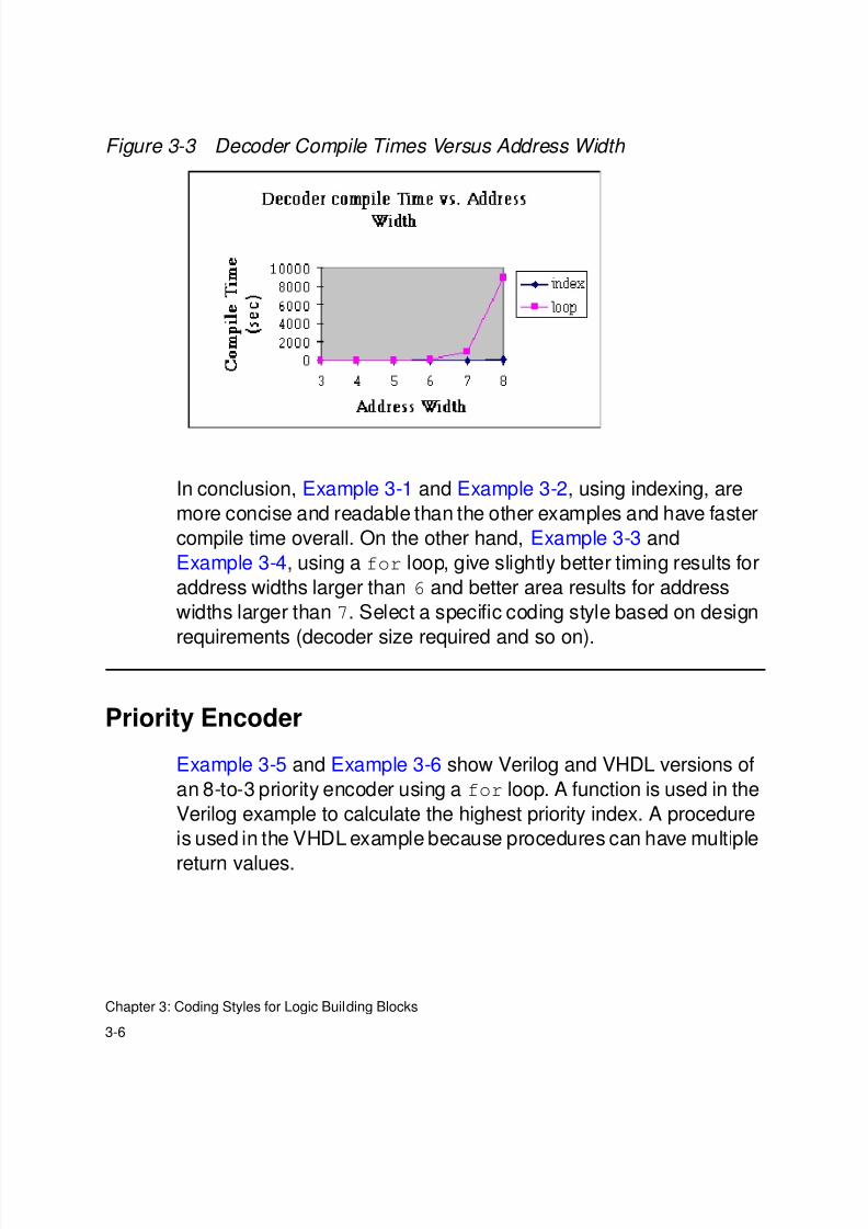
Table 3-3 and Figure 3-3 show compile time for the decoder coding
styles described previously.
Table 3-3 Compile Time (Seconds) for Decoder Coding Styles
Input Address Width 3 4 5 6 7 8
Index 2 3 11 18 58 132
Loop 16 13 42 163 946 9000
8/8/2019 Syn Coding
http://slidepdf.com/reader/full/syn-coding 52/84
3-6
Chapter 3: Coding Styles for Logic Building Blocks
Figure 3-3 Decoder Compile Times Versus Address Width
In conclusion, Example 3-1 and Example 3-2, using indexing, are
more concise and readable than the other examples and have faster
compile time overall. On the other hand, Example 3-3 and
Example 3-4, using a for loop, give slightly better timing results for
address widths larger than 6 and better area results for address
widths larger than 7. Select a specific coding style based on design
requirements (decoder size required and so on).
Priority Encoder
Example 3-5 and Example 3-6 show Verilog and VHDL versions of
an 8-to-3 priority encoder using a for loop. A function is used in the
Verilog example to calculate the highest priority index. A procedure
is used in the VHDL example because procedures can have multiple
return values.
8/8/2019 Syn Coding
http://slidepdf.com/reader/full/syn-coding 53/84
8/8/2019 Syn Coding
http://slidepdf.com/reader/full/syn-coding 54/84
3-8
Chapter 3: Coding Styles for Logic Building Blocks
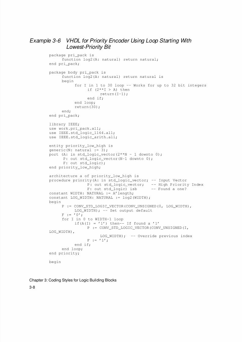
Example 3-6 VHDL for Priority Encoder Using Loop Starting With Lowest-Priority Bit
package pri_pack is
function log2(A: natural) return natural;end pri_pack;
package body pri_pack is
function log2(A: natural) return natural is
begin
for I in 1 to 30 loop -- Works for up to 32 bit integers
if (2**I > A) then
return(I-1);
end if;
end loop;
return(30);
end;
end pri_pack;
library IEEE;
use work.pri_pack.all;
use IEEE.std_logic_1164.all;
use IEEE.std_logic_arith.all;
entity priority_low_high is
generic(N: natural := 3);
port (A: in std_logic_vector(2**N - 1 downto 0);
P: out std_logic_vector(N-1 downto 0);
F: out std_logic);
end priority_low_high;
architecture a of priority_low_high is
procedure priority(A: in std_logic_vector; -- Input VectorP: out std_logic_vector; -- High Priority Index
F: out std_logic) isb -- Found a one?
constant WIDTH: NATURAL := A’length;
constant LOG_WIDTH: NATURAL := log2(WIDTH);
begin
P := CONV_STD_LOGIC_VECTOR(CONV_UNSIGNED(0, LOG_WIDTH),
LOG_WIDTH); -- Set output default
F := ’0’;
for I in 0 to WIDTH-1 loop
if(A(I) = ’1’) then-- If found a ’1’
P := CONV_STD_LOGIC_VECTOR(CONV_UNSIGNED(I,LOG_WIDTH),
LOG_WIDTH); -- Override previous index
F := ’1’;end if;
end loop;
end priority;
begin
8/8/2019 Syn Coding
http://slidepdf.com/reader/full/syn-coding 55/84

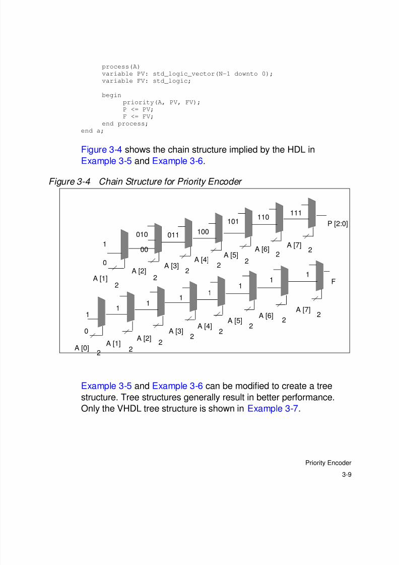
8/8/2019 Syn Coding
http://slidepdf.com/reader/full/syn-coding 56/84
3-10
Chapter 3: Coding Styles for Logic Building Blocks
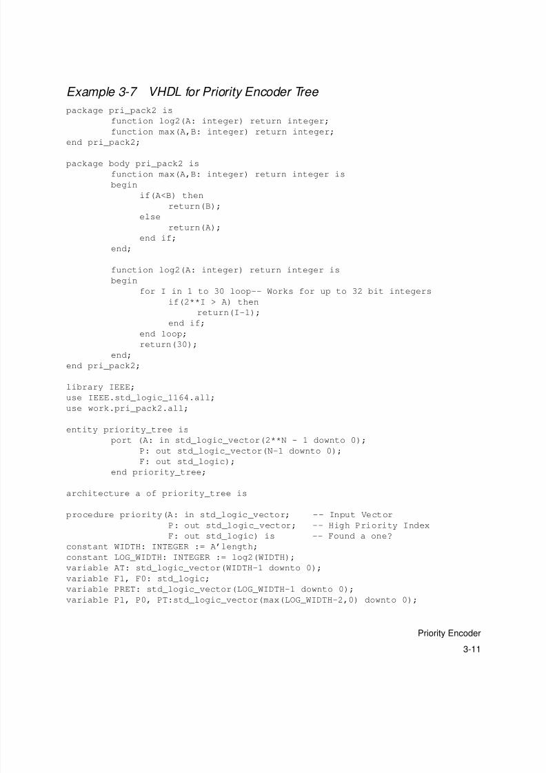
Using recursion in VHDL gives you the ability to create a priority
encoder in a tree structure. Example 3-7 uses recursive procedure
calls to generate a tree structure for a priority encoder.
8/8/2019 Syn Coding
http://slidepdf.com/reader/full/syn-coding 57/84
3-11
Priority Encoder
Example 3-7 VHDL for Priority Encoder Tree
package pri_pack2 is
function log2(A: integer) return integer;
function max(A,B: integer) return integer;end pri_pack2;
package body pri_pack2 is
function max(A,B: integer) return integer is
begin
if(A<B) then
return(B);
else
return(A);
end if;
end;
function log2(A: integer) return integer isbegin
for I in 1 to 30 loop-- Works for up to 32 bit integers
if(2**I > A) then
return(I-1);
end if;
end loop;
return(30);
end;
end pri_pack2;
library IEEE;
use IEEE.std_logic_1164.all;
use work.pri_pack2.all;
entity priority_tree is
port (A: in std_logic_vector(2**N - 1 downto 0);
P: out std_logic_vector(N-1 downto 0);
F: out std_logic);
end priority_tree;
architecture a of priority_tree is
procedure priority(A: in std_logic_vector; -- Input Vector
P: out std_logic_vector; -- High Priority Index
F: out std_logic) is -- Found a one?
constant WIDTH: INTEGER := A’length;
constant LOG_WIDTH: INTEGER := log2(WIDTH);
variable AT: std_logic_vector(WIDTH-1 downto 0);
variable F1, F0: std_logic;
variable PRET: std_logic_vector(LOG_WIDTH-1 downto 0);
variable P1, P0, PT:std_logic_vector(max(LOG_WIDTH-2,0) downto 0);
8/8/2019 Syn Coding
http://slidepdf.com/reader/full/syn-coding 58/84
3-12
Chapter 3: Coding Styles for Logic Building Blocks
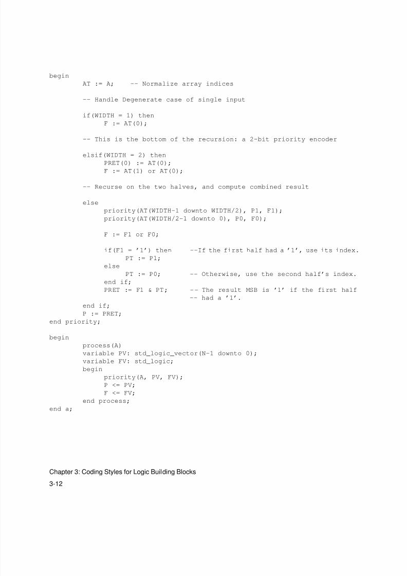
begin
AT := A; -- Normalize array indices
-- Handle Degenerate case of single input
if(WIDTH = 1) then
F := AT(0);
-- This is the bottom of the recursion: a 2-bit priority encoder
elsif(WIDTH = 2) then
PRET(0) := AT(0);
F := AT(1) or AT(0);
-- Recurse on the two halves, and compute combined result
elsepriority(AT(WIDTH-1 downto WIDTH/2), P1, F1);
priority(AT(WIDTH/2-1 downto 0), P0, F0);
F := F1 or F0;
if(F1 = ’1’) then --If the first half had a ’1’, use its index.
PT := P1;
else
PT := P0; -- Otherwise, use the second half’s index.
end if;
PRET := F1 & PT; -- The result MSB is ’1’ if the first half
-- had a ’1’.
end if;
P := PRET;
end priority;
begin
process(A)
variable PV: std_logic_vector(N-1 downto 0);
variable FV: std_logic;
begin
priority(A, PV, FV);
P <= PV;
F <= FV;
end process;end a;
8/8/2019 Syn Coding
http://slidepdf.com/reader/full/syn-coding 59/84
3-13
Priority Encoder
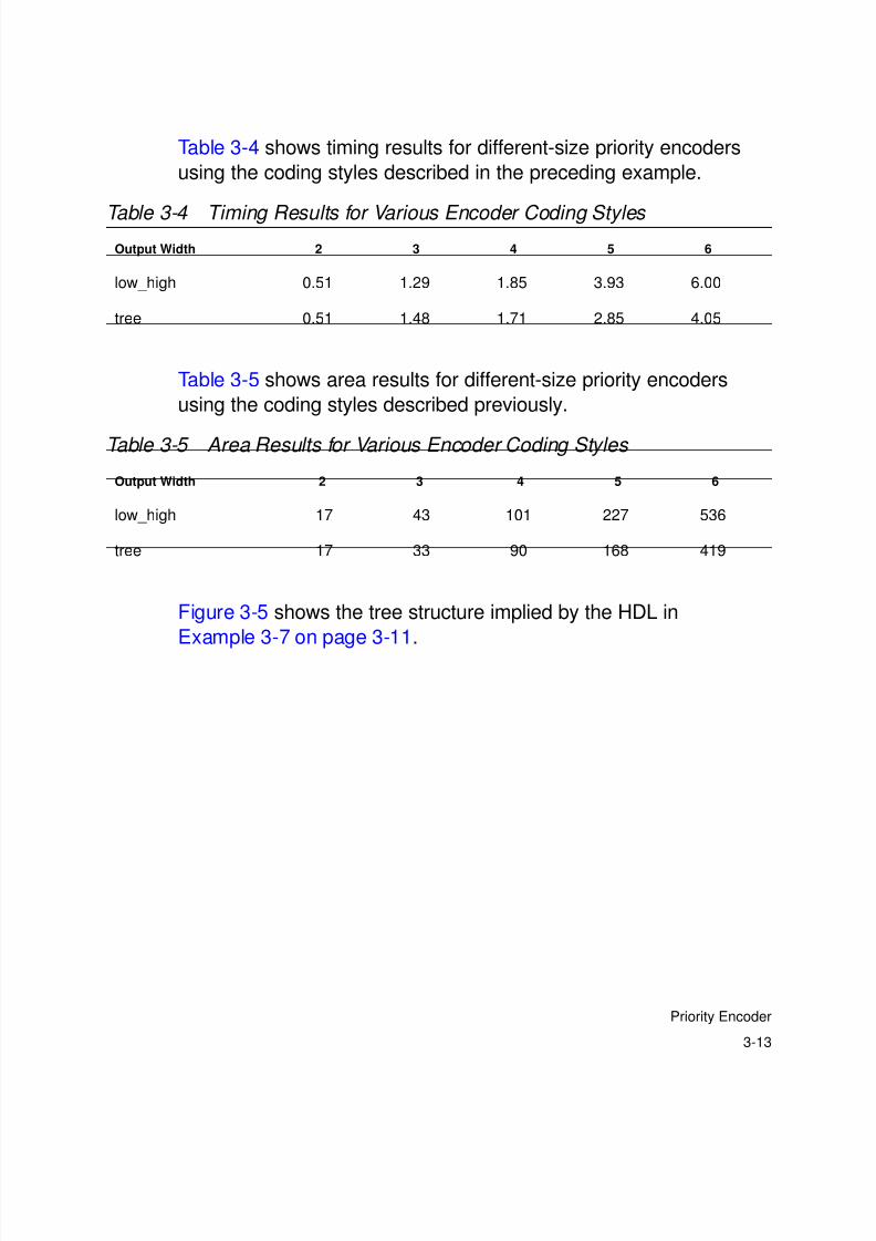
Table 3-4 shows timing results for different-size priority encoders
using the coding styles described in the preceding example.
Table 3-5 shows area results for different-size priority encoders
using the coding styles described previously.
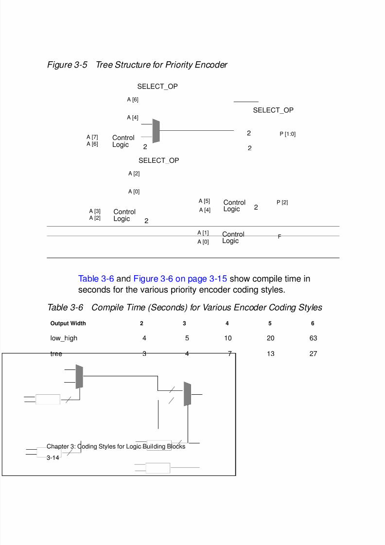
Figure 3-5 shows the tree structure implied by the HDL in
Example 3-7 on page 3-11.
Table 3-4 Timing Results for Various Encoder Coding Styles Output Width 2 3 4 5 6
low_high 0.51 1.29 1.85 3.93 6.00
tree 0.51 1.48 1.71 2.85 4.05
Table 3-5 Area Results for Various Encoder Coding Styles
Output Width 2 3 4 5 6
low_high 17 43 101 227 536
tree 17 33 90 168 419
8/8/2019 Syn Coding
http://slidepdf.com/reader/full/syn-coding 60/84
3-14
Chapter 3: Coding Styles for Logic Building Blocks
Figure 3-5 Tree Structure for Priority Encoder
Table 3-6 and Figure 3-6 on page 3-15 show compile time in
seconds for the various priority encoder coding styles.
Table 3-6 Compile Time (Seconds) for Various Encoder Coding Styles
Output Width 2 3 4 5 6
low_high 4 5 10 20 63
tree 3 4 7 13 27
A [2]
A [0]
SELECT_OP
ControlLogic 2
A [3]
A [2]
A [6]
A [4]
SELECT_OP
ControlLogic 2
A [7]
A [6]
SELECT_OP
2
2 P [1:0]
LogicControlA [5]
A [4] 2P [2]
LogicControlA [1]
A [0]F
8/8/2019 Syn Coding
http://slidepdf.com/reader/full/syn-coding 61/84
3-15
Reduction XOR
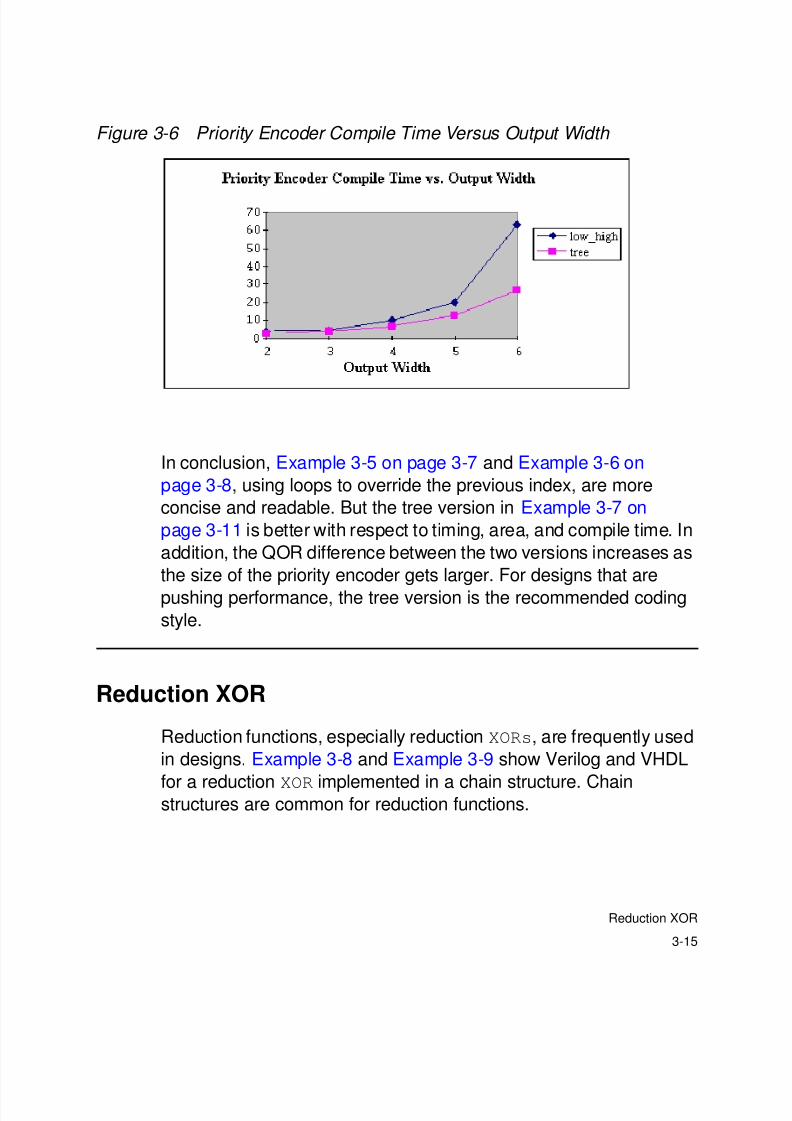
Figure 3-6 Priority Encoder Compile Time Versus Output Width
In conclusion, Example 3-5 on page 3-7 and Example 3-6 on
page 3-8, using loops to override the previous index, are more
concise and readable. But the tree version in Example 3-7 on
page 3-11 is better with respect to timing, area, and compile time. In
addition, the QOR difference between the two versions increases as
the size of the priority encoder gets larger. For designs that are
pushing performance, the tree version is the recommended coding
style.
Reduction XOR
Reduction functions, especially reduction XORs, are frequently used
in designs. Example 3-8 and Example 3-9 show Verilog and VHDL
for a reduction XOR implemented in a chain structure. Chainstructures are common for reduction functions.

8/8/2019 Syn Coding
http://slidepdf.com/reader/full/syn-coding 62/84
3-16
Chapter 3: Coding Styles for Logic Building Blocks
Example 3-8 Verilog for Reduction XOR Chain
module XOR_reduce (data_in, data_out);
parameter N = 5;
input [N-1:0] data_in;
output data_out;
reg data_out;
function XOR_reduce_func;
input [N-1:0] data;
integer I;
begin
XOR_reduce_func = 0;
for (I = N-1; I >= 0; I=I-1)
XOR_reduce_func = XOR_reduce_func ^ data[I];
end
endfunction
always @(data_in)
begin
data_out <= XOR_reduce_func(data_in);
end
endmodule
Example 3-9 VHDL for Reduction XOR Chain
library IEEE;
use IEEE.std_logic_1164.all;
entity XOR_reduce is
generic (N: natural := 5);
port (data_in: in std_logic_vector(N-1 downto 0);data_out: out std_logic);
end XOR_reduce;
architecture one of XOR_reduce is
function XOR_reduce_func(data:std_logic_vector)return std_logic is
variable result : std_logic;
begin
result := ’0’;
for I in data’RANGE loop
result := result XOR data(I);
end loop;
return result;
end;
begin
data_out <= XOR_reduce_func(data_in);
end one;
8/8/2019 Syn Coding
http://slidepdf.com/reader/full/syn-coding 63/84
3-17
Reduction XOR
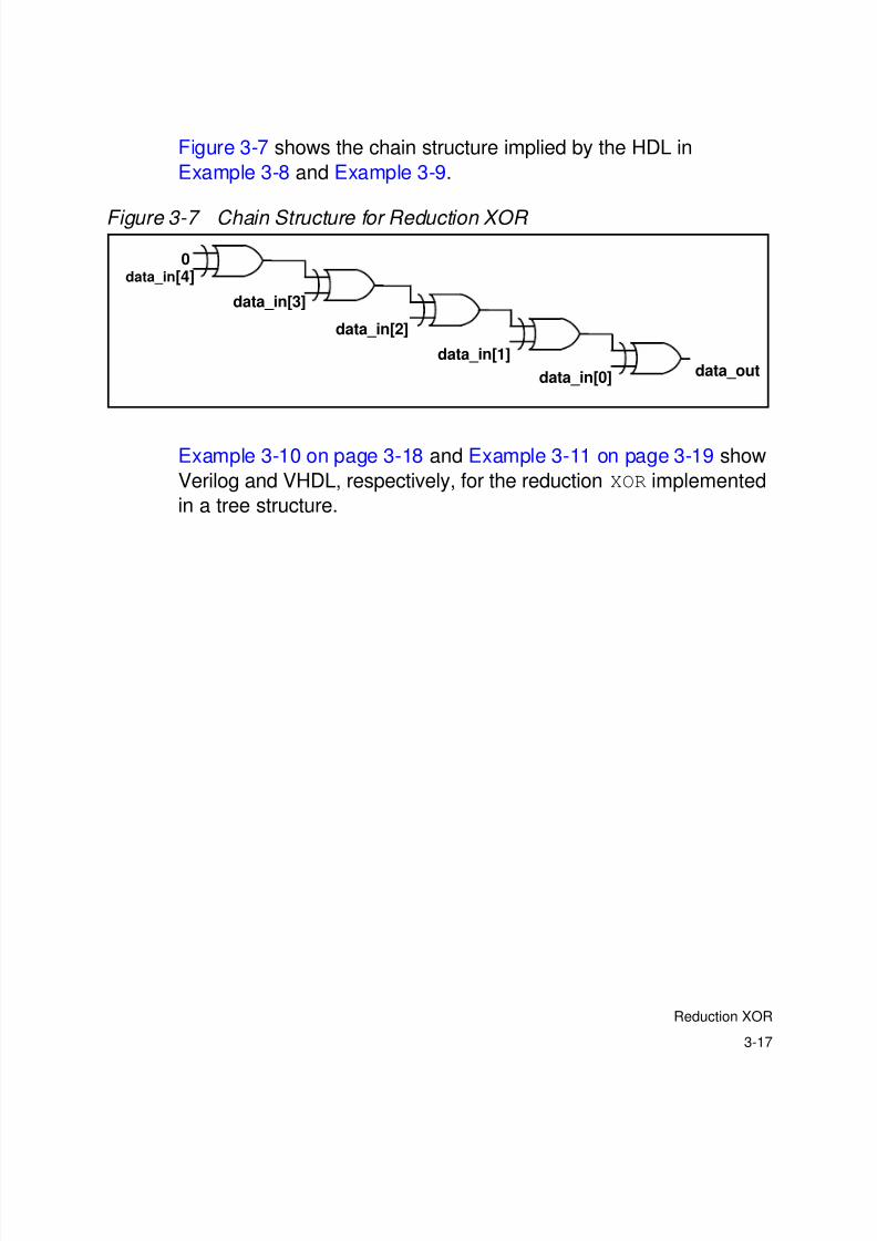
Figure 3-7 shows the chain structure implied by the HDL in
Example 3-8 and Example 3-9.
Figure 3-7 Chain Structure for Reduction XOR
Example 3-10 on page 3-18 and Example 3-11 on page 3-19 show
Verilog and VHDL, respectively, for the reduction XOR implemented
in a tree structure.
data_in[4]
data_in[3]
data_in[2]
data_in[1]
data_in[0]
0
data_out

8/8/2019 Syn Coding
http://slidepdf.com/reader/full/syn-coding 64/84
3-18
Chapter 3: Coding Styles for Logic Building Blocks
Example 3-10 Verilog for XOR Tree
module XOR_tree(data_in, data_out);
parameter N = 5;
parameter logN = 3;
input [N-1:0] data_in;
output data_out;
reg data_out;
function even;
input [31:0] num;
begin
even = ~num[0];
end
endfunction
function XOR_tree_func;
input [N-1:0] data;
integer I, J, K, NUM;
reg [N-1:0] temp, result;
begin
temp[N-1:0] = data_in[N-1:0];
NUM = N;
for (K=logN-1; K>=0; K=K-1)
begin
J = (NUM+1)/2;
J = J-1;
if (even(NUM))
for (I=NUM-1; I>=0; I=I-2)
begin
result[J] = temp[I] ^ temp[I-1];
J = J-1;
endelse
begin
for (I=NUM-1; I>=1; I=I-2)
begin
result[J] = temp[I] ^ temp[I-1];
J = J-1;
end
result[0] = temp[0];
end
temp[N-1:0] = result[N-1:0];
NUM = (NUM+1)/2;
end
XOR_tree_func = result[0];end
endfunction
always @(data_in)
begin
data_out <= XOR_tree_func(data_in);
8/8/2019 Syn Coding
http://slidepdf.com/reader/full/syn-coding 65/84
3-19
Reduction XOR
end
endmodule
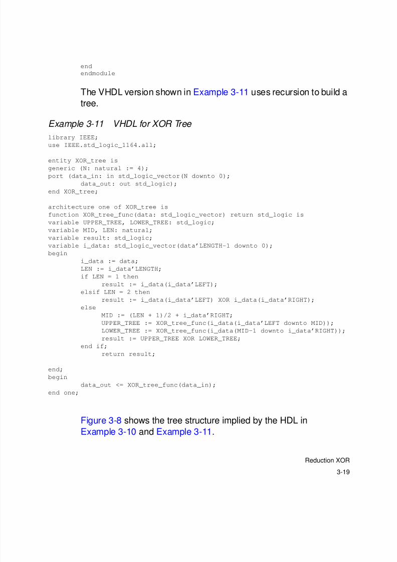
The VHDL version shown in Example 3-11 uses recursion to build a
tree.
Example 3-11 VHDL for XOR Tree
library IEEE;
use IEEE.std_logic_1164.all;
entity XOR_tree is
generic (N: natural := 4);
port (data_in: in std_logic_vector(N downto 0);
data_out: out std_logic);
end XOR_tree;
architecture one of XOR_tree is
function XOR_tree_func(data: std_logic_vector) return std_logic is
variable UPPER_TREE, LOWER_TREE: std_logic;
variable MID, LEN: natural;
variable result: std_logic;
variable i_data: std_logic_vector(data’LENGTH-1 downto 0);
begin
i_data := data;
LEN := i_data’LENGTH;
if LEN = 1 then
result := i_data(i_data’LEFT);
elsif LEN = 2 then
result := i_data(i_data’LEFT) XOR i_data(i_data’RIGHT);
else
MID := (LEN + 1)/2 + i_data’RIGHT;
UPPER_TREE := XOR_tree_func(i_data(i_data’LEFT downto MID));
LOWER_TREE := XOR_tree_func(i_data(MID-1 downto i_data’RIGHT));
result := UPPER_TREE XOR LOWER_TREE;
end if;
return result;
end;
begin
data_out <= XOR_tree_func(data_in);
end one;
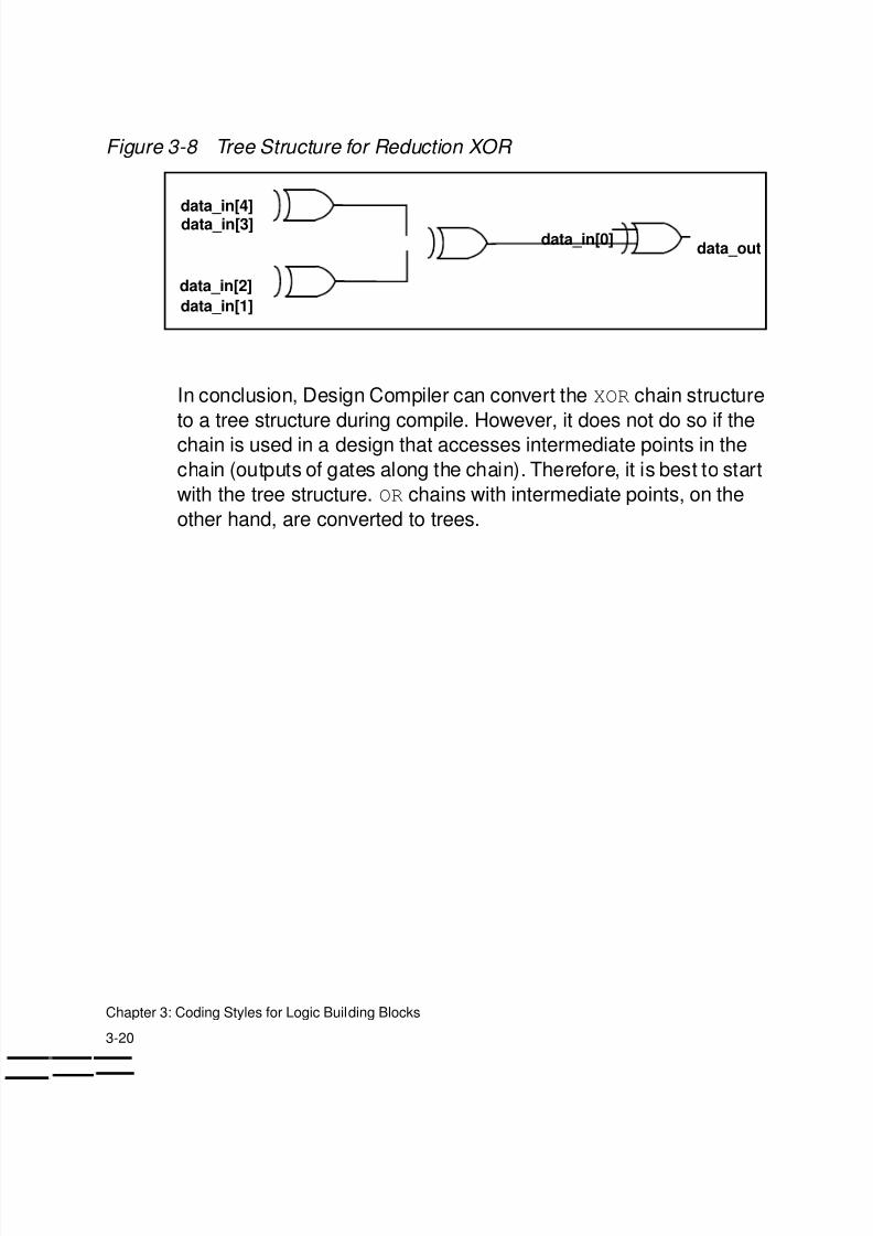
Figure 3-8 shows the tree structure implied by the HDL in
Example 3-10 and Example 3-11.
8/8/2019 Syn Coding
http://slidepdf.com/reader/full/syn-coding 66/84
3-20
Chapter 3: Coding Styles for Logic Building Blocks
Figure 3-8 Tree Structure for Reduction XOR
In conclusion, Design Compiler can convert the XOR chain structure
to a tree structure during compile. However, it does not do so if the
chain is used in a design that accesses intermediate points in the
chain (outputs of gates along the chain). Therefore, it is best to start
with the tree structure. OR chains with intermediate points, on the
other hand, are converted to trees.
data_in[4]data_in[3]
data_in[2]
data_in[1]
data_in[0]data_out
8/8/2019 Syn Coding
http://slidepdf.com/reader/full/syn-coding 67/84
4-1
4High-Performance Coding Techniques 4
This chapter contains examples utilizing various high-performance
coding techniques.
This chapter contains the following sections:
• Data-Path Duplication
• Operator in if Condition
8/8/2019 Syn Coding
http://slidepdf.com/reader/full/syn-coding 68/84
4-2
Chapter 4: High-Performance Coding Techniques
Data-Path Duplication
The following examples illustrate how to duplicate logic in HDL toimprove timing.
In Example 4-1 and Example 4-2, CONTROL is a late arriving input
signal. The goal is to reduce the logic from CONTROL to the output
port COUNT.
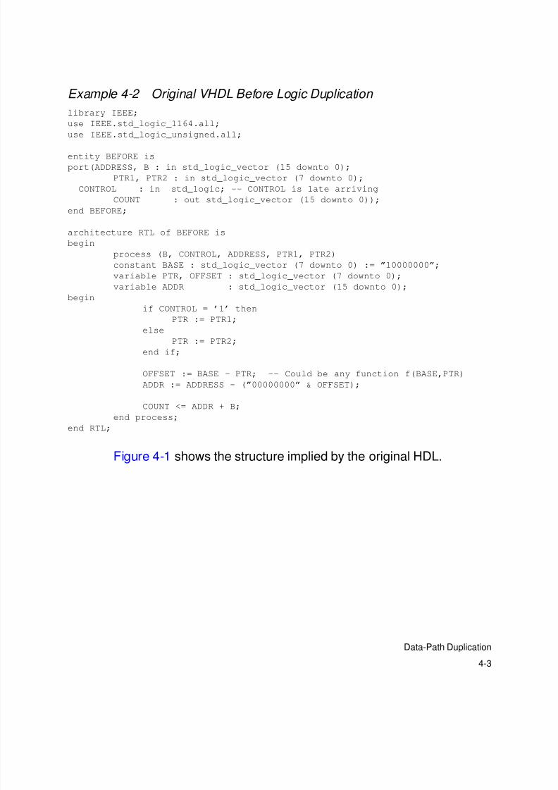
Example 4-1 Original Verilog Before Logic Duplication
module BEFORE (ADDRESS, PTR1, PTR2, B, CONTROL, COUNT);
input [7:0] PTR1,PTR2;
input [15:0] ADDRESS, B;input CONTROL; // CONTROL is late arriving
output [15:0] COUNT;
parameter [7:0] BASE = 8’b10000000;
wire [7:0] PTR, OFFSET;
wire [15:0] ADDR;
assign PTR = (CONTROL == 1’b1) ? PTR1 : PTR2;
assign OFFSET = BASE - PTR; //Could be any function f(BASE,PTR)
assign ADDR = ADDRESS - {8’h00, OFFSET};
assign COUNT = ADDR + B;
endmodule
8/8/2019 Syn Coding
http://slidepdf.com/reader/full/syn-coding 69/84
4-3
Data-Path Duplication
Example 4-2 Original VHDL Before Logic Duplication
library IEEE;
use IEEE.std_logic_1164.all;
use IEEE.std_logic_unsigned.all;
entity BEFORE is
port(ADDRESS, B : in std_logic_vector (15 downto 0);
PTR1, PTR2 : in std_logic_vector (7 downto 0);
CONTROL : in std_logic; -- CONTROL is late arriving
COUNT : out std_logic_vector (15 downto 0));
end BEFORE;
architecture RTL of BEFORE is
begin
process (B, CONTROL, ADDRESS, PTR1, PTR2)
constant BASE : std_logic_vector (7 downto 0) := ”10000000”;
variable PTR, OFFSET : std_logic_vector (7 downto 0);variable ADDR : std_logic_vector (15 downto 0);
begin
if CONTROL = ’1’ then
PTR := PTR1;
else
PTR := PTR2;
end if;
OFFSET := BASE - PTR; -- Could be any function f(BASE,PTR)
ADDR := ADDRESS - (”00000000” & OFFSET);
COUNT <= ADDR + B;
end process;end RTL;
Figure 4-1 shows the structure implied by the original HDL.
8/8/2019 Syn Coding
http://slidepdf.com/reader/full/syn-coding 70/84
4-4
Chapter 4: High-Performance Coding Techniques
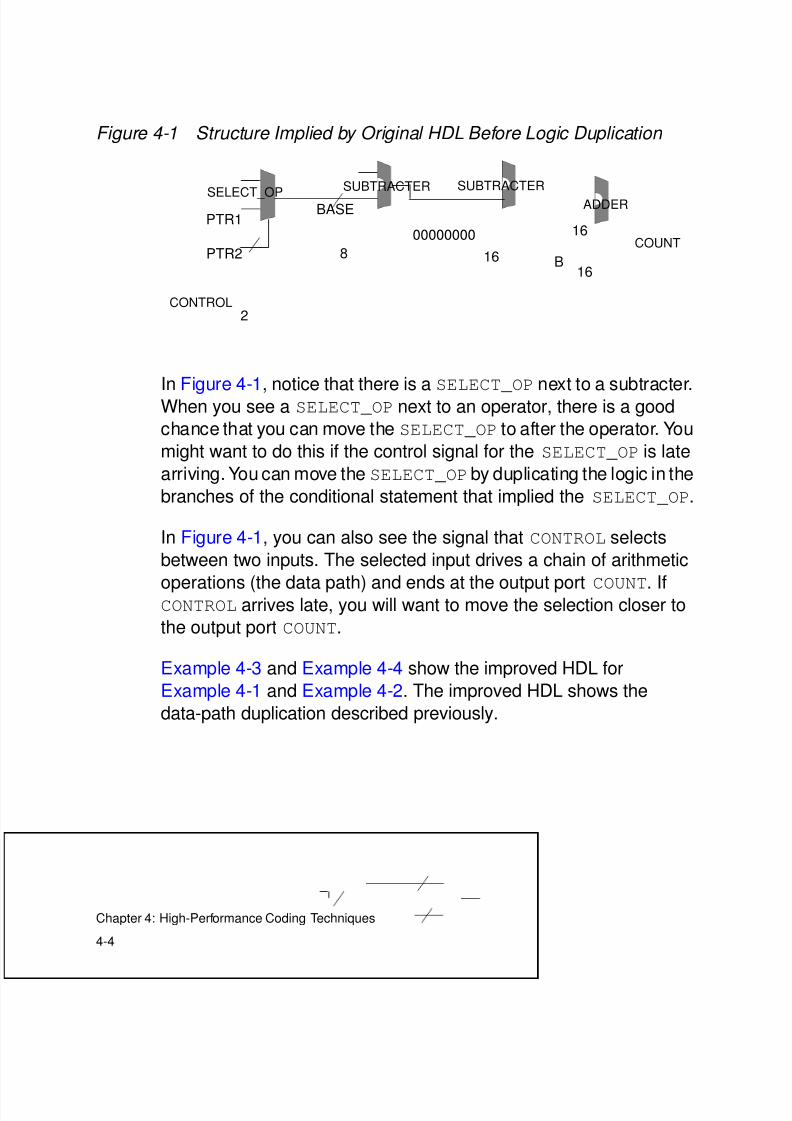
Figure 4-1 Structure Implied by Original HDL Before Logic Duplication
In Figure 4-1, notice that there is a SELECT_OP next to a subtracter.When you see a SELECT_OP next to an operator, there is a good
chance that you can move the SELECT_OP to after the operator. You
might want to do this if the control signal for the SELECT_OP is late
arriving. You can move the SELECT_OP by duplicating the logic in the
branches of the conditional statement that implied the SELECT_OP.
In Figure 4-1, you can also see the signal that CONTROL selects
between two inputs. The selected input drives a chain of arithmetic
operations (the data path) and ends at the output port COUNT. IfCONTROL arrives late, you will want to move the selection closer to
the output port COUNT.
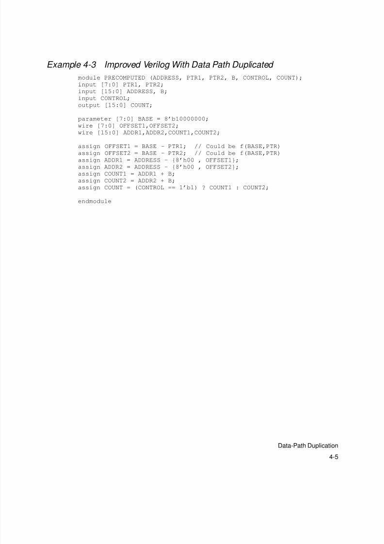
Example 4-3 and Example 4-4 show the improved HDL for
Example 4-1 and Example 4-2. The improved HDL shows the
data-path duplication described previously.
SELECT_OP
2
PTR1
PTR2
CONTROL
SUBTRACTER SUBTRACTER
ADDERBASE
8
00000000
16COUNT
16
B16
8/8/2019 Syn Coding
http://slidepdf.com/reader/full/syn-coding 71/84
4-5
Data-Path Duplication
Example 4-3 Improved Verilog With Data Path Duplicated
module PRECOMPUTED (ADDRESS, PTR1, PTR2, B, CONTROL, COUNT);
input [7:0] PTR1, PTR2;
input [15:0] ADDRESS, B;
input CONTROL;
output [15:0] COUNT;
parameter [7:0] BASE = 8’b10000000;
wire [7:0] OFFSET1,OFFSET2;
wire [15:0] ADDR1,ADDR2,COUNT1,COUNT2;
assign OFFSET1 = BASE - PTR1; // Could be f(BASE,PTR)
assign OFFSET2 = BASE - PTR2; // Could be f(BASE,PTR)
assign ADDR1 = ADDRESS - {8’h00 , OFFSET1};
assign ADDR2 = ADDRESS - {8’h00 , OFFSET2};
assign COUNT1 = ADDR1 + B;
assign COUNT2 = ADDR2 + B;
assign COUNT = (CONTROL == 1’b1) ? COUNT1 : COUNT2;
endmodule
8/8/2019 Syn Coding
http://slidepdf.com/reader/full/syn-coding 72/84
4-6
Chapter 4: High-Performance Coding Techniques
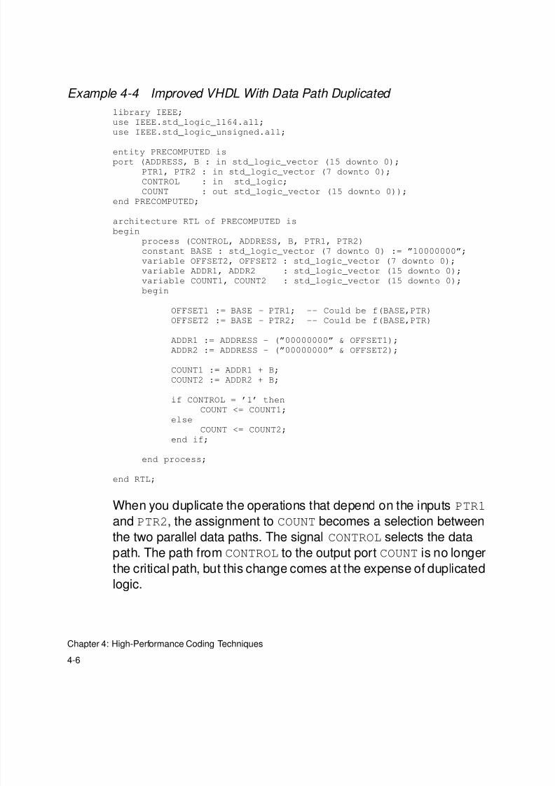
Example 4-4 Improved VHDL With Data Path Duplicated
library IEEE;
use IEEE.std_logic_1164.all;
use IEEE.std_logic_unsigned.all;
entity PRECOMPUTED is
port (ADDRESS, B : in std_logic_vector (15 downto 0);
PTR1, PTR2 : in std_logic_vector (7 downto 0);
CONTROL : in std_logic;
COUNT : out std_logic_vector (15 downto 0));
end PRECOMPUTED;
architecture RTL of PRECOMPUTED is
begin
process (CONTROL, ADDRESS, B, PTR1, PTR2)
constant BASE : std_logic_vector (7 downto 0) := ”10000000”;
variable OFFSET2, OFFSET2 : std_logic_vector (7 downto 0);
variable ADDR1, ADDR2 : std_logic_vector (15 downto 0);
variable COUNT1, COUNT2 : std_logic_vector (15 downto 0);
begin
OFFSET1 := BASE - PTR1; -- Could be f(BASE,PTR)
OFFSET2 := BASE - PTR2; -- Could be f(BASE,PTR)
ADDR1 := ADDRESS - (”00000000” & OFFSET1);
ADDR2 := ADDRESS - (”00000000” & OFFSET2);
COUNT1 := ADDR1 + B;
COUNT2 := ADDR2 + B;
if CONTROL = ’1’ then
COUNT <= COUNT1;else
COUNT <= COUNT2;
end if;
end process;
end RTL;
When you duplicate the operations that depend on the inputs PTR1
and PTR2, the assignment to COUNT becomes a selection between
the two parallel data paths. The signal CONTROL selects the data
path. The path from CONTROL to the output port COUNT is no longerthe critical path, but this change comes at the expense of duplicated
logic.
8/8/2019 Syn Coding
http://slidepdf.com/reader/full/syn-coding 73/84
4-7
Data-Path Duplication
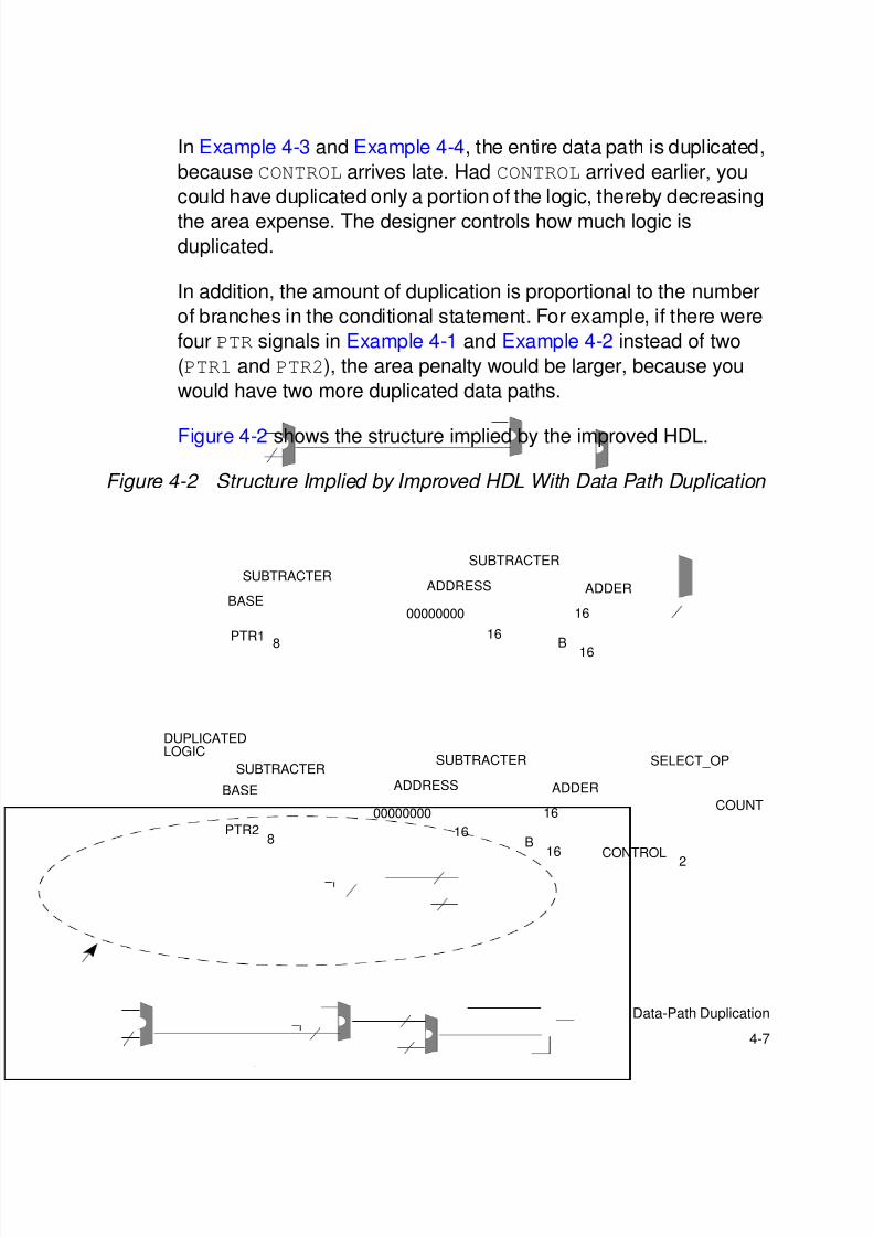
In Example 4-3 and Example 4-4, the entire data path is duplicated,
because CONTROL arrives late. Had CONTROL arrived earlier, you
could have duplicated only a portion of the logic, thereby decreasing
the area expense. The designer controls how much logic isduplicated.
In addition, the amount of duplication is proportional to the number
of branches in the conditional statement. For example, if there were
four PTR signals in Example 4-1 and Example 4-2 instead of two
(PTR1 and PTR2), the area penalty would be larger, because you
would have two more duplicated data paths.
Figure 4-2 shows the structure implied by the improved HDL.
Figure 4-2 Structure Implied by Improved HDL With Data Path Duplication
SELECT_OP
2
PTR1
PTR2
CONTROL
SUBTRACTERSUBTRACTER
ADDERBASE
8
00000000
16
COUNT
16
B16
ADDRESS
DUPLICATEDLOGIC
SUBTRACTERSUBTRACTER
ADDER
00000000
16
16
B16
ADDRESSBASE
8
8/8/2019 Syn Coding
http://slidepdf.com/reader/full/syn-coding 74/84
4-8
Chapter 4: High-Performance Coding Techniques
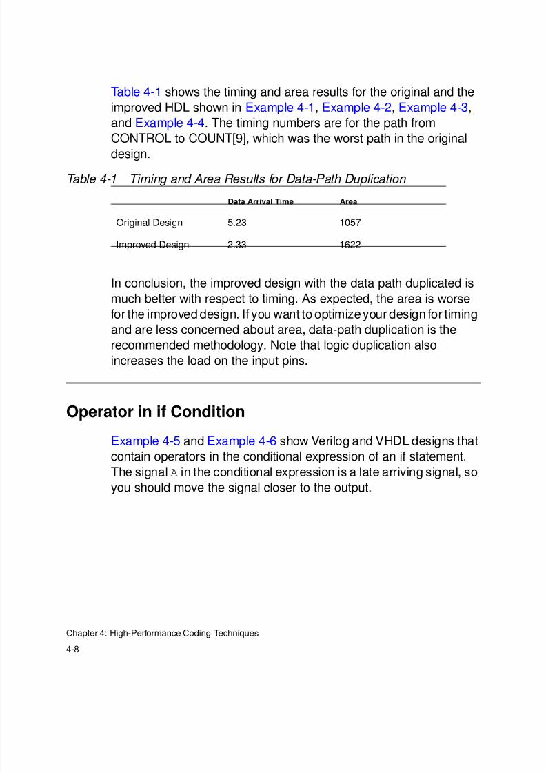
Table 4-1 shows the timing and area results for the original and the
improved HDL shown in Example 4-1, Example 4-2, Example 4-3,
and Example 4-4. The timing numbers are for the path from
CONTROL to COUNT[9], which was the worst path in the originaldesign.
In conclusion, the improved design with the data path duplicated is
much better with respect to timing. As expected, the area is worse
for the improved design. If you want to optimizeyour design for timing
and are less concerned about area, data-path duplication is the
recommended methodology. Note that logic duplication also
increases the load on the input pins.
Operator in if Condition
Example 4-5 and Example 4-6 show Verilog and VHDL designs that
contain operators in the conditional expression of an if statement.
The signal A in the conditional expression is a late arriving signal, so
you should move the signal closer to the output.
Table 4-1 Timing and Area Results for Data-Path Duplication
Data Arrival Time Area
Original Design 5.23 1057
Improved Design 2.33 1622
8/8/2019 Syn Coding
http://slidepdf.com/reader/full/syn-coding 75/84
4-9
Operator in if Condition
Example 4-5 Original Verilog With Operator in Conditional Expression
module cond_oper(A, B, C, D, Z);
parameter N = 8;
input [N-1:0] A, B, C, D; //A is late arriving
output [N-1:0] Z;
reg [N-1:0] Z;
always @(A or B or C or D)
begin
if (A + B < 24)
Z <= C;
else
Z <= D;
end
endmodule
Example 4-6 Original VHDL With Operator in Conditional Expression
library IEEE;
use IEEE.std_logic_1164.all;
use IEEE.std_logic_arith.all;
use IEEE.std_logic_unsigned.all;
entity cond_oper is
generic(N: natural := 8);
port(A, B: in std_logic_vector(N-1 downto 0);
-- A is late arriving
C, D: in std_logic_vector(N-1 downto 0);
Z: out std_logic_vector(N-1 downto 0));
end cond_oper;
architecture one of cond_oper is
begin
process(A, B, C, D)
begin
if (A + B < 24) then
Z <= C;
else
Z <= D;
end if;
end process;
end one;
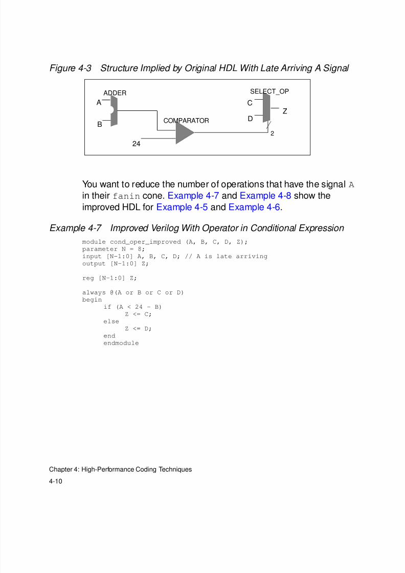
Figure 4-3 shows the structure implied by the original HDL in
Example 4-5 and Example 4-6. The signal A is an input to the adder
in Figure 4-3.
8/8/2019 Syn Coding
http://slidepdf.com/reader/full/syn-coding 76/84
4-10
Chapter 4: High-Performance Coding Techniques
Figure 4-3 Structure Implied by Original HDL With Late Arriving A Signal
You want to reduce the number of operations that have the signal A
in their fanin cone. Example 4-7 and Example 4-8 show the
improved HDL for Example 4-5 and Example 4-6.
Example 4-7 Improved Verilog With Operator in Conditional Expression
module cond_oper_improved (A, B, C, D, Z);
parameter N = 8;
input [N-1:0] A, B, C, D; // A is late arriving
output [N-1:0] Z;
reg [N-1:0] Z;
always @(A or B or C or D)
beginif (A < 24 - B)
Z <= C;
else
Z <= D;
end
endmodule
ADDER
A
BCOMPARATOR
SELECT_OP
C
DZ
24
2
8/8/2019 Syn Coding
http://slidepdf.com/reader/full/syn-coding 77/84
4-11
Operator in if Condition
Example 4-8 Improved VHDL With Operator in Conditional Expression
library IEEE;
use IEEE.std_logic_1164.all;
use IEEE.std_logic_arith.all;
use IEEE.std_logic_unsigned.all;
entity cond_oper_improved is
generic (N : natural := 8);
port (A, B : in std_logic_vector(N-1 downto 0);
-- A is late arriving
C, D : in std_logic_vector(N-1 downto 0);
Z : out std_logic_vector(N-1 downto 0));
end cond_oper_improved;
architecture one of cond_oper_improved is
begin
process(A, B, C, D)
begin
if (A < 24 - B) then
Z <= C;
else
Z <= D;
end if;
end process;
end one;
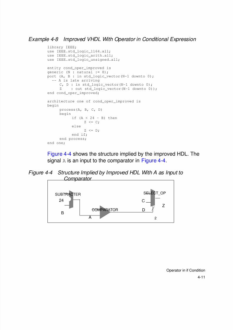
Figure 4-4 shows the structure implied by the improved HDL. The
signal A is an input to the comparator in Figure 4-4.
Figure 4-4 Structure Implied by Improved HDL With A as Input to Comparator
24
BCOMPARATOR
SELECT_OP
C
DZ
2
SUBTRACTER
A
8/8/2019 Syn Coding
http://slidepdf.com/reader/full/syn-coding 78/84
4-12
Chapter 4: High-Performance Coding Techniques
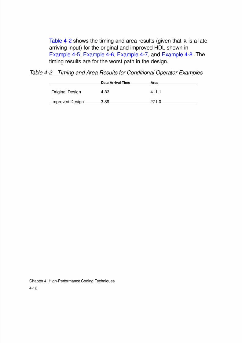
Table 4-2 shows the timing and area results (given that A is a late
arriving input) for the original and improved HDL shown in
Example 4-5, Example 4-6, Example 4-7, and Example 4-8. The
timing results are for the worst path in the design.
Table 4-2 Timing and Area Results for Conditional Operator Examples
Data Arrival Time Area
Original Design 4.33 411.1
Improved Design 3.89 271.0
8/8/2019 Syn Coding
http://slidepdf.com/reader/full/syn-coding 79/84
5-1
5General Coding Style Guidelines 5
This chapter lists some general guidelines for writing HDL.
This chapter contains the following sections:
• Unintentional Latch Inference• Incomplete Sensitivity Lists
• Unnecessary Calculations in for Loops
• Resource Sharing

8/8/2019 Syn Coding
http://slidepdf.com/reader/full/syn-coding 80/84

8/8/2019 Syn Coding
http://slidepdf.com/reader/full/syn-coding 81/84
5-3
Incomplete Sensitivity Lists
For Verilog, you can also use the HDL Compiler full_case
directive with caution to tell HDL Compiler that the case statement is
fully specified. For additional information on the full_case
directive, see the HDL Compiler for Verilog Reference Manual .
To get HDL Compiler to issue a warning when latches are inferred,
set the variablehdlin_check_no_latch to true before HDL input.
You can also check the inference report after HDL input to see if any
latches were inferred.
For additional information on inference reports and HDL examples to
infer flip-flops and latches, see the HDL Compiler for Verilog
Reference Manual .
Incomplete Sensitivity Lists
Incomplete sensitivity lists can cause a simulation/synthesis
mismatch. HDL Compiler issues warnings for signals that are read in
a process or in an always block but are not listed in the sensitivity
list. Sensitivity lists do not affect the logic generated by HDL
Compiler, but an incomplete sensitivity list can cause unexpected
simulation results, because the process does not trigger when
necessary.
Consider the Verilog and VHDL code segments in Example 5-3 and
Example 5-4.
Example 5-3 Verilog With Missing Signal in Sensitivity List
always @(d or clr)
if (clr)
q = 1’b0
else if (e)
q = d;
8/8/2019 Syn Coding
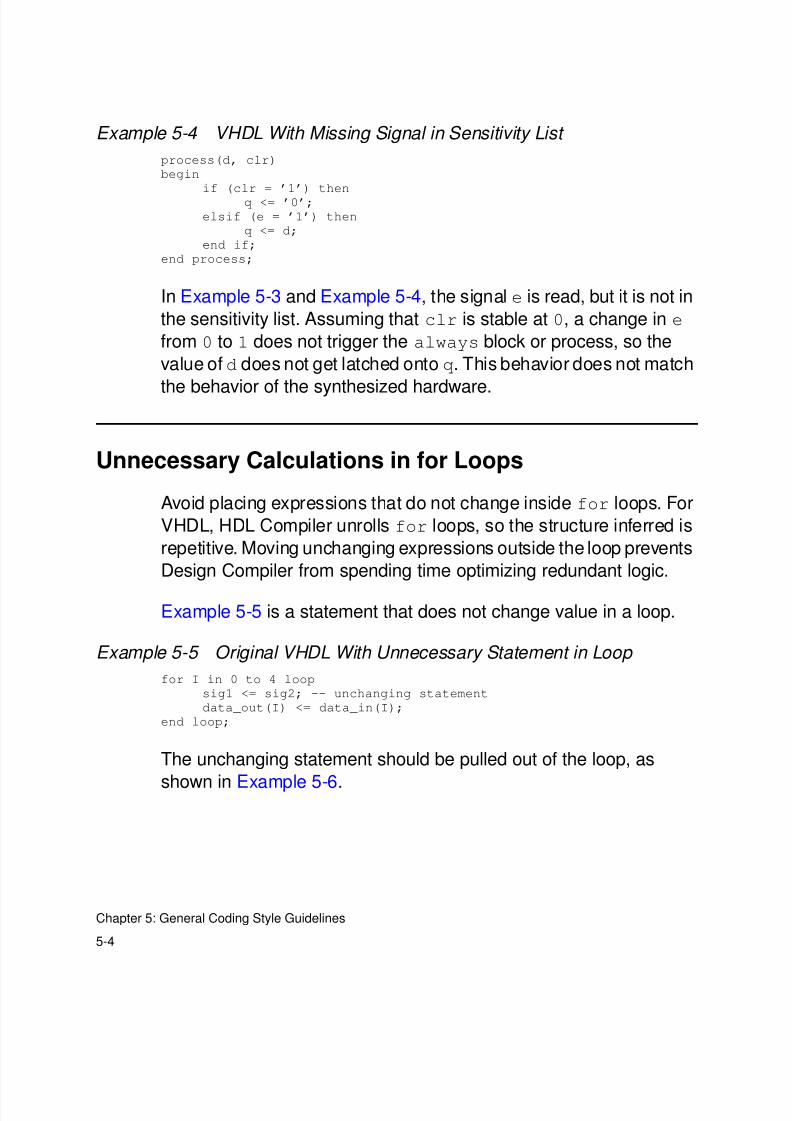
http://slidepdf.com/reader/full/syn-coding 82/84
8/8/2019 Syn Coding
http://slidepdf.com/reader/full/syn-coding 83/84
5-5
Resource Sharing
Example 5-6 Improved VHDL With Statement Pulled out of Loop
sig1 <= sig2;
for I in 0 to 4 loop
data_out(I) <= data_in(I);
end loop;
Resource Sharing
Arithmetic operators are shared only if they occur in mutually
exclusive branches of if-then-else or case statements. Operators in
loops and conditional assignments in Verilog (using the conditional
operator ?) are not shared.
Example 5-7 shows a Verilog statement that uses the conditional
operator. Resource sharing does not take place for this example.
Example 5-7 No Resource Sharing for Conditional Operator in Verilog
z = (cond)?(a+b):(c+d);
However, resource sharing does take place for the equivalent
if-then-else statement in Example 5-8.
Example 5-8 Resource Sharing for equivalent if-then-else in Verilog
if (cond)
z = a+b;
else
z = c+d;
For additional information about resource sharing, see the HDL
Compiler for Verilog Reference Manual or the VHDL Compiler
Reference Manual .

8/8/2019 Syn Coding
http://slidepdf.com/reader/full/syn-coding 84/84