Symposia on “ACL Femoral Footprint Revisited: For … · the ACL with a single bundle...
16
Symposia on “ACL Femoral Footprint Revisited: For Accurate/Anatomical Tunnel Creation” Fu, Freddie [email protected] Anatomic ACL reconstruction Shino, Konsei [email protected] How I use the ACL footprint in ACL reconstruction Ferretti, Mario [email protected] ACL reconstruction using the native ACL insertion sites Spalding, Tim [email protected] Anatomic single-bundle reconstruction using the ACL footprint Siebold, Rainer [email protected] Anatomic double-bundle reconstruction using the ACL footprint Discussion and possible presentation of cases by the entire panel (10 min)
Transcript of Symposia on “ACL Femoral Footprint Revisited: For … · the ACL with a single bundle...
Symposia on “ACL Femoral Footprint Revisited: For Accurate/Anatomical Tunnel Creation” Fu, Freddie [email protected] Anatomic ACL reconstruction Shino, Konsei [email protected] How I use the ACL footprint in ACL reconstruction Ferretti, Mario [email protected] ACL reconstruction using the native ACL insertion sites Spalding, Tim [email protected] Anatomic single-bundle reconstruction using the ACL footprint Siebold, Rainer [email protected] Anatomic double-bundle reconstruction using the ACL footprint Discussion and possible presentation of cases by the entire panel (10 min)

NOTES:
Anatomic ACL Reconstruction Freddie H. Fu, MD, DSc (Hon), DPs (Hon);
University of Pittsburgh, Department of Orthopaedic Surgery Correspondence: [email protected]
Anatomic Double Bundle ACL Reconstruction Pre-operatively, the ACL insertion site and ACL length can be measured on the sagittal MRI.
The ACL inclination angle can also be measured, as can be seen further below.
42° 51°42° 51°
The MRI can also be used to measure the size of the certain autografts. Both the patellar
tendon and the quadriceps tendon size can be measured on the sagittal MRI sequence. As can be appreciated below, the quadriceps tendon is often much larger than the patellar tendon and can offer more autograft substance.

2
Anatomic double-bundle ACL reconstruction is an “Insertion Site Surgery”. We utilize
three portals: Lateral Portal (LP), Medial Portal (MP), and Accessory Medial Portal (AMP).
We routinely place the arthroscope in the MP and work through the AMP. In doing so,
visualization of the femoral insertion of the ACL is greatly enhanced and the need for notchplasty is virtually eliminated.1
The anatomic insertion sites of each native ACL bundle are marked on the femur and tibia with a thermal device, with care taken to preserve the border of the bundles for later reference. This is a critical step in identifying the correct placement of the tunnels, and is performed prior to resection of any residual ACL tissue. In addition, the length and width of the AM and PL bundle insertion site are measured as references to decide tunnel diameters. The surgery is individualized for each patient.
There is a large area on the lateral wall of intercondylar notch for potential non-anatomic tunnel placement. Our preliminary data suggested that it may occupy more than 65% of the area on the wall.
A “lateral bifurcate ridge” is often seen on the femoral insertion between the AM and PL bundles, where as a “lateral intercondylar ridge” is often seen on the upper limit of both the AM and PL bundles. These are useful surgical landmarks in addition to the native insertion fibers.2-3
Notchplasty destroys the femoral anatomy of the ACL and is not necessary if medial and accessory medial portals are used.

3
The tibial and femur tunnels are placed at their native insertion site, which were previously marked by thermal device.
The PL femoral tunnel is always drilled through the anteromedial portal. The primary advantage of drilling trans-tibially for the AM femoral tunnel is the creation of a longer tunnel which diverges from the PL femoral tunnel, and we routinely attempt this approach first before using the accessory medial portal. However, sometimes it can’t reach the anatomic insertion site. In that case, the tunnel will be drill through the anteromedial portal.
Finally, the PL graft is passed first, followed by the AM graft. Femoral fixation is typically performed with an EndoButton.
Post-operatively, the MRI can be used to compare the pre- and post-op insertion site size to measure how much of the insertion site is restored. In addition, the pre- and post-operative inclination angle can be compared. After anatomic ACL reconstruction, the ACL inclination angle should be similar to the native ACL inclination angle.
3D CT scan can be used to evaluate tunnel position.
Anatomic Single Bundle ACL Reconstruction Except for the one bundle augmentation
(performed when only one of the two native bundles are torn), there are a few other scenarios where we prefer to perform single bundle surgery (30%):4

4
• Small native ACL insertion site (< 14mm) • Open growth plate • Severe arthritic changes • Multiple knee ligament injuries • Severe bone bruises • Narrow intercondylar notch
Our single bundle surgery is performed
with careful attention to soft tissue and bony landmarks. We carefully investigate the rupture pattern of the ACL and we identify the native ACL insertion sites -- just as we do in double bundle ACL surgery. Then, the tibial tunnel is placed at between the native insertion sites of the AM bundle and PL bundles, or at the center of the entire tibial insertion site.
The distance from anterior margin of ACL footprint to center of tibial tunnel should be measured, and the femoral tunnel should be placed at the same distance from the posterior margin (knee in 90º flexion) of the femoral ACL footprint.
One Bundle Augmentation
In cases only the AM or the PL bundle was torn, we save the intact bundle and “augment” the ACL with a single bundle reconstruction – either the AM or PL, whichever one is torn.
Biological Enhancement
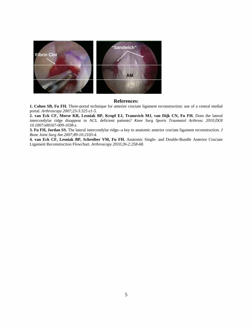
Typically the graft heals to the bone through bleeding created by drilling the tunnels. We have begun using a “fibrin clot” to try to enhance the healing of the two bundles
together and to the bone. A fibrin clot is created from the patient’s own blood by gently stirring it in a glass beaker
for 5 – 10 minutes and contains many of the same growth factors advertised as being present in commercially available blood preparation products, such as platelet rich plasma (PRP).
5
References: 1. Cohen SB, Fu FH. Three-portal technique for anterior cruciate ligament reconstruction: use of a central medial portal. Arthroscopy 2007;23-3:325 e1-5. 2. van Eck CF, Morse KR, Lesniak BP, Kropf EJ, Tranovich MJ, van Dijk CN, Fu FH. Does the lateral intercondylar ridge disappear in ACL deficient patients? Knee Surg Sports Traumatol Arthrosc 2010;DOI 10.1007/s00167-009-1038-z. 3. Fu FH, Jordan SS. The lateral intercondylar ridge--a key to anatomic anterior cruciate ligament reconstruction. J Bone Joint Surg Am 2007;89-10:2103-4. 4. van Eck CF, Lesniak BP, Schreiber VM, Fu FH. Anatomic Single- and Double-Bundle Anterior Cruciate Ligament Reconstruction Flowchart. Arthroscopy 2010;26-2:258-68.
Fibrin ClotFibrin Clot“Sandwich”
AM
“Sandwich”
AM
Use of the residentʼs ridge as an arthroscopic landmark of the anterior border of
the ACL femoral attachment
K. Shino, MD
Osaka, Japan
The residentʼs ridge is a nearly-longitudinal ridge, 3 quarters of the way back on
the roof to lateral border of the notch. The idea to use this ridge as a landmark of
the anterior border for femoral tunnel placement is not new but was already
described by Clancy et al some years ago. However, the technique to
arthroscopically identify the residentʼs ridge without bony notchplasty in patients
with chronic ACL insufficiency had not been established.
We developed a technique to find out a linear ridge running proximo-distal in a
posterior one-third of the lateral notch wall by removal of superficial soft tissue
with radiofrequency energy. We created a socket with a rectangular aperture of
5 × 10 mm just behind the ridge. Postoperatively, three-dimensional computed
tomography (3-D CT) was taken to geographically identify the location of the
ridge using the socket as a reference.
Arthroscopically, a linear ridge running from superior-anterior to
inferior-posterior on the lateral notch wall was consistently observed 7-10 mm
anterior to the posterior articular cartilage margin of the lateral femoral condyle.
The 3-D CT pictures proved the arthroscopically identified ridge to be the
residentʼs ridge. As the residentʼs ridge is arthroscopically identifiable after
non-mechanical removal of the soft tissues without bony notchplasty, it could be
used as a useful landmark for anatomical femoral tunnel drilling in arthroscopic
ACL reconstruction.
1
Anatomic single-bundle reconstruction using the ACL footprint:
The Ruler technique
Tim Spalding
Consultant Orthopaedic Surgeon, University Hospital Coventry and Warwickshire NHS Trust
Honorary Associate Professor, University of Warwick, England
Introduction
Identification of the lateral intercondylar and
bifurcate ridges which act as osseous landmarks
ridges has been shown to be an accurate and
reliable method to locate the native ACL femoral
insertion site [1] and the true entry point for the
femoral tunnel. The presence of these ridges is
however variable and they may not be seen [2].
Reports describe identifying and lateral
intercondylar ridge in 100% of 60 knees at
arthroscopy and the bifurcate ridge in 82% in one
series [1] and then 88% and 48% respectively in
another [3].
In the absence of consistent intra-operative
visualisation, knee surgeons have used a variety of
methods such as preoperative and intra-operative
radiographic images, computer navigation and
arthroscopic measuring devices with triangulation
to locate the native ACL femoral insertion site [4-
7]. Radiological techniques utilise the Bernard-
Hertel radiographic quadrant method on a true
lateral image to define the insertion point of the
ACL [8]. This requires an intra-operative true
lateral view on an image intensifier which
although accurate, adds to the complexity and cost
of the procedure making it potentially unpopular.
Use of 3D CT has been used to validate femoral
tunnel position post operatively [9 - 11].
Kaseta et al. noted that the center of the ACL was
within 2mm of an arthroscopic reference point
located at the junction of a line drawn distally
from the most proximal corner of the articular
margin on the lateral wall of the notch and a
perpendicular line drawn to the most posterior
point of the condyle [12]. This study along with
observations of the anatomy of the femoral
attachment of the ACL by Freddie Fu and Charlie
Brown led to the development of the Ruler
Technique for localizing the start point of the
femoral tunnel guidewire. We have validated this
technique using post-operative 3D CT scans
comparing the tunnel position to published
radiographic measurements and to our previous
antero-medial portal surgical technique using an
offset guide.
The Ruler Technique: operative procedure
Ipsilateral semi-tendinosis and gracilis tendons are
harvested and prepared into a four-strand graft
using a whip-stitch.
Three arthroscopic portals are then made in the
knee to allow optimal vision and instrumentation.
A high anterolateral (AL) portal is made at the
level of the inferior pole of the patella, adjacent to
the lateral border of the patellar tendon. A high
anteromedial (AM) visualization portal is inserted
at the level of the inferior pole of the patella,
adjacent to the medial border of the patellar
tendon. Finally an accessory anteromedial portal
(AAM) is located inferior and medial to the
anteromedial portal just above the level of the
medial meniscus [13]. This portal is made under
direct vision to avoid damage to the medial
meniscus.
The notch is then prepared by using an
arthroscopic shaver device to remove scar tissue
and the remaining ACL stump with care taken to
preserve the bony anatomy (Figure 2a). A
radiofrequency probe is then used to remove the
residual ACL stump and to identify the proximal
margin of the articular cartilage as a specific
reference point.
2
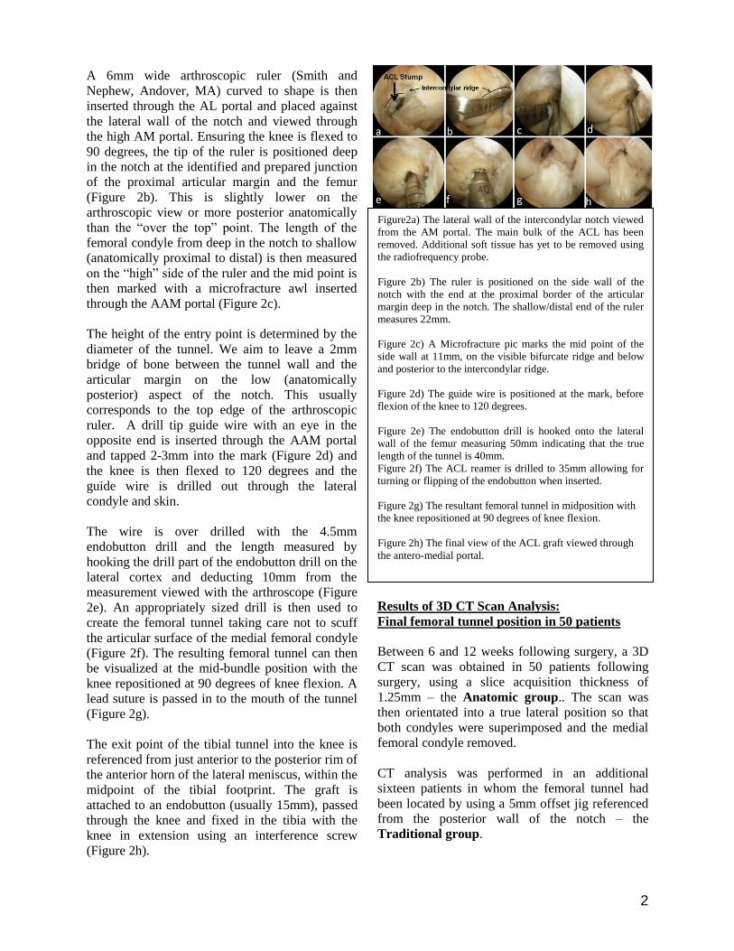
A 6mm wide arthroscopic ruler (Smith and
Nephew, Andover, MA) curved to shape is then
inserted through the AL portal and placed against
the lateral wall of the notch and viewed through
the high AM portal. Ensuring the knee is flexed to
90 degrees, the tip of the ruler is positioned deep
in the notch at the identified and prepared junction
of the proximal articular margin and the femur
(Figure 2b). This is slightly lower on the
arthroscopic view or more posterior anatomically
than the “over the top” point. The length of the
femoral condyle from deep in the notch to shallow
(anatomically proximal to distal) is then measured
on the “high” side of the ruler and the mid point is
then marked with a microfracture awl inserted
through the AAM portal (Figure 2c).
The height of the entry point is determined by the
diameter of the tunnel. We aim to leave a 2mm
bridge of bone between the tunnel wall and the
articular margin on the low (anatomically
posterior) aspect of the notch. This usually
corresponds to the top edge of the arthroscopic
ruler. A drill tip guide wire with an eye in the
opposite end is inserted through the AAM portal
and tapped 2-3mm into the mark (Figure 2d) and
the knee is then flexed to 120 degrees and the
guide wire is drilled out through the lateral
condyle and skin.
The wire is over drilled with the 4.5mm
endobutton drill and the length measured by
hooking the drill part of the endobutton drill on the
lateral cortex and deducting 10mm from the
measurement viewed with the arthroscope (Figure
2e). An appropriately sized drill is then used to
create the femoral tunnel taking care not to scuff
the articular surface of the medial femoral condyle
(Figure 2f). The resulting femoral tunnel can then
be visualized at the mid-bundle position with the
knee repositioned at 90 degrees of knee flexion. A
lead suture is passed in to the mouth of the tunnel
(Figure 2g).
The exit point of the tibial tunnel into the knee is
referenced from just anterior to the posterior rim of
the anterior horn of the lateral meniscus, within the
midpoint of the tibial footprint. The graft is
attached to an endobutton (usually 15mm), passed
through the knee and fixed in the tibia with the
knee in extension using an interference screw
(Figure 2h).
Results of 3D CT Scan Analysis:
Final femoral tunnel position in 50 patients
Between 6 and 12 weeks following surgery, a 3D
CT scan was obtained in 50 patients following
surgery, using a slice acquisition thickness of
1.25mm – the Anatomic group.. The scan was
then orientated into a true lateral position so that
both condyles were superimposed and the medial
femoral condyle removed.
CT analysis was performed in an additional
sixteen patients in whom the femoral tunnel had
been located by using a 5mm offset jig referenced
from the posterior wall of the notch – the
Traditional group.
Figure2a) The lateral wall of the intercondylar notch viewed
from the AM portal. The main bulk of the ACL has been
removed. Additional soft tissue has yet to be removed using
the radiofrequency probe.
Figure 2b) The ruler is positioned on the side wall of the
notch with the end at the proximal border of the articular
margin deep in the notch. The shallow/distal end of the ruler
measures 22mm.
Figure 2c) A Microfracture pic marks the mid point of the
side wall at 11mm, on the visible bifurcate ridge and below
and posterior to the intercondylar ridge.
Figure 2d) The guide wire is positioned at the mark, before
flexion of the knee to 120 degrees.
Figure 2e) The endobutton drill is hooked onto the lateral
wall of the femur measuring 50mm indicating that the true
length of the tunnel is 40mm.
Figure 2f) The ACL reamer is drilled to 35mm allowing for
turning or flipping of the endobutton when inserted.
Figure 2g) The resultant femoral tunnel in midposition with
the knee repositioned at 90 degrees of knee flexion.
Figure 2h) The final view of the ACL graft viewed through
the antero-medial portal.
3
The centre of the femoral tunnel was then
determined using the grid system described by
Bernard and Hertel [8]. The grid was positioned so
that the superior arm was positioned against the
roof of the notch corresponding to Blumensaat‟s
line and the posterior section against the posterior
aspect of the lateral femoral condyle. The location
of each tunnel on this grid was recorded expressed
as co-ordinates along Blumensaat‟s line from
proximal to distal and along the opposite axis for
anterior to posterior
(Figure 3).
The mean positions for the
„anatomic‟ group and the
„traditional‟ group were
then calculated and related
to the optimal position.
We determined this
optimal position by the mean co-ordinates reported
by previous authors (Table 1) [7, 8, 11, 14, 15, 16].
This put the mean mid bundle position at point
28% on the proximal to distal axis and 35% on
the perpendicular axis.
Table 1) The co-ordinates of the ideal position of the ACL
insertion on Bernard and Hertel‟s grid as reported in the
literature.
Statistical analysis of the distance from the centre
of the tunnel to the ideal literature point was
performed using the Mann-Whitney U test for the
independent, continuous data and analysed using
Statistical Package for Social Sciences (SPSS,
Chicago, Il).
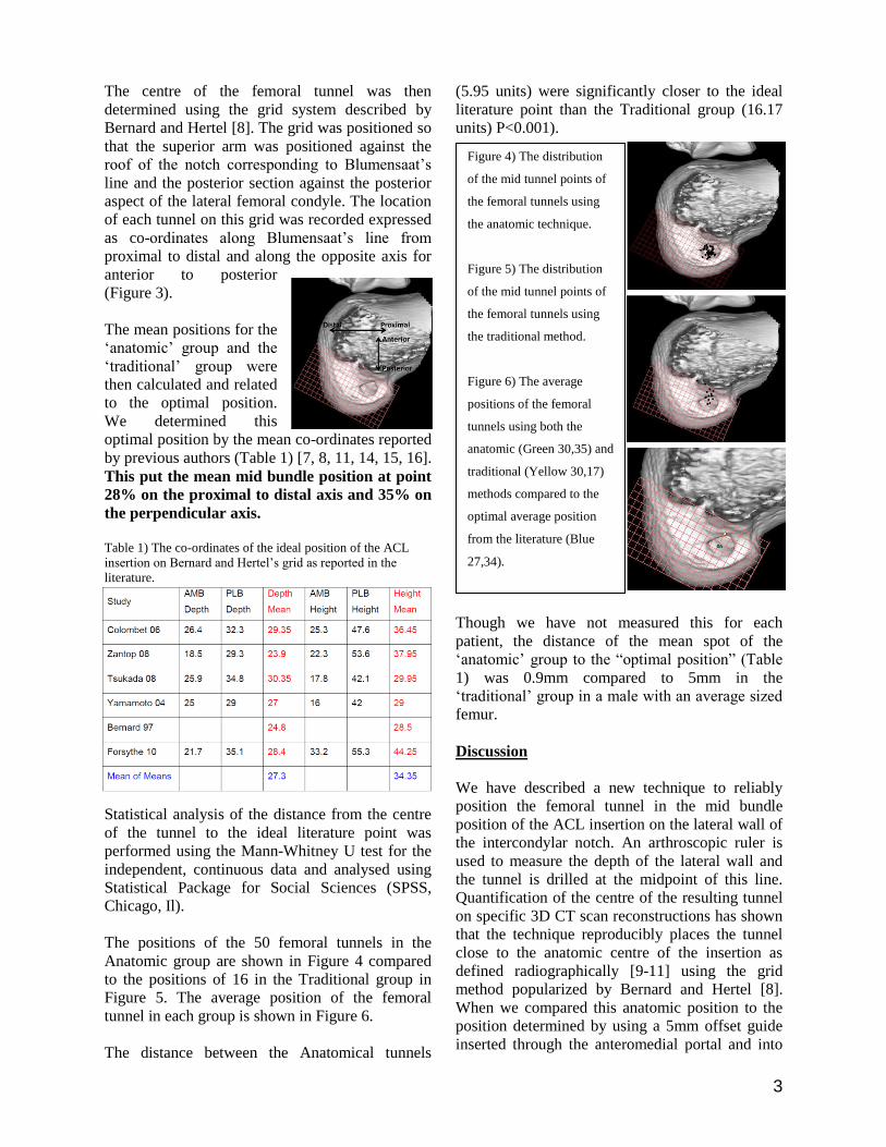
The positions of the 50 femoral tunnels in the
Anatomic group are shown in Figure 4 compared
to the positions of 16 in the Traditional group in
Figure 5. The average position of the femoral
tunnel in each group is shown in Figure 6.
The distance between the Anatomical tunnels
(5.95 units) were significantly closer to the ideal
literature point than the Traditional group (16.17
units) P<0.001).
Though we have not measured this for each
patient, the distance of the mean spot of the
„anatomic‟ group to the “optimal position” (Table
1) was 0.9mm compared to 5mm in the
„traditional‟ group in a male with an average sized
femur.
Discussion
We have described a new technique to reliably
position the femoral tunnel in the mid bundle
position of the ACL insertion on the lateral wall of
the intercondylar notch. An arthroscopic ruler is
used to measure the depth of the lateral wall and
the tunnel is drilled at the midpoint of this line.
Quantification of the centre of the resulting tunnel
on specific 3D CT scan reconstructions has shown
that the technique reproducibly places the tunnel
close to the anatomic centre of the insertion as
defined radiographically [9-11] using the grid
method popularized by Bernard and Hertel [8].
When we compared this anatomic position to the
position determined by using a 5mm offset guide
inserted through the anteromedial portal and into
Figure 4) The distribution
of the mid tunnel points of
the femoral tunnels using
the anatomic technique.
Figure 5) The distribution
of the mid tunnel points of
the femoral tunnels using
the traditional method.
Figure 6) The average
positions of the femoral
tunnels using both the
anatomic (Green 30,35) and
traditional (Yellow 30,17)
methods compared to the
optimal average position
from the literature (Blue
27,34).

4
The AM portal view of the
lateral wall showing the
intercondylar ridge A and
the bifurcate ridge B. The
microfracture pic hole at
the mid portion of the
lateral condyle lies on the
bifurcate ridge.
the “over the top position”, there was a substantial
difference in tunnel location.
The advantage of this current reported technique is
that it produces an accurate mid footprint
placement of the femoral tunnel. The technique is
readily teachable and reproducible with a close
grouping of the measured points on the overall
grid placed on the cutaway 3D reconstruction scan
image.
Conclusions
The use of the ruler technique produced femoral
tunnels comparable to published radiographic
criteria used for tunnel placement and is
reproducible and accurate. Our study has
demonstrated that the ruler method is a safe,
simple, quick and cost effective method for the
establishment of an anatomical single-bundle ACL
femoral tunnel.
Acknowledgments
Charlie Brown, Abu Dhabi, UAE
Jonathan Bird, Knee Fellow UHCW England
Simon Spencer, Knee Fellow UHCW England
Pete Thompson, Knee Surgeon UHCW
References
1) Steiner M. Anatomic single bundle ACL reconstruction.
Sports Med Arthrosc 2009;17(4):247-251.
2) Ferretti M, Ekdahl M, Shen W, Fu FH. Osseous landmarks
of the femoral attachment of the anterior cruciate ligament: an
anatomic study. Arthroscopy 2007;23(11):1218-1225.
3) Van Eck CF, Martins CA, Vyas SM, Celentano U, van Dijk
CN, Fu FH. Femoral intercondylar notch shape and
dimensions in ACL injured patients. Knee Surg Sports
Traumatol Arthrosc 2010;18(9):1257-1262.
4) Nakagawa T, Takeda H, Nakajima K et al. Intraoperative 3
dimensional imaging-based navigation-assisted anatomic
double bundle anterior cruciate ligament reconstruction.
Arthroscopy 2008;24(10:1161-1167.
5) Silver AG, Kaar SG, Grisell MK, Reagan JM, Farrow LD.
Comparison between rigid and flexible systems for drilling
the femoral tunnel through an anteromedial portal in anterior
cruciate ligament reconstruction. Arthroscopy
2010;26(6):790-795.
6) Chitnavis JP, Karthikesaligam A, Macdonald A, Brown C.
Radiation risk from fluoroscopically assisted anterior cruciate
ligament recontruction. Ann R Coll Surg Eng 2010;92(4):330-
334.
7) Tsukada H, Ishibashi Y, Tsuda E, Fukuda A, Toh S.
Anatomical analysis of the anterior cruciate ligament femoral
and tibial footprints. J Orthop Sci 2008;13(2):122-129.
8) Bernard M, Hertel P. Intraoperative and postoperative
insertion control of anterior cruciate ligament-plasty. A
radiologic measuring method (quadrant method).
Unfallchirurg 1996;99(5):332-340.
9) Basdekis G, Christel P, Anne F. Validation of the position
of the femoral tunnels in anatomic double bundle ACL
reconstruction with 3D CT scan. Knee Surg Sports Traumatol
Arthrosc 2009;17(9):1089-1094.
10) Kopf S, Forsythe B, Wong AK, Tashman S, Anderst W,
Irrgang JJ, Fu FH. Non-anatomic tunnel position in traditional
transtibial single bundle anterior cruciate ligament
reconstruction evaluated by three dimensional computer
tomography. J Bone Joint Surg Am 2010;92(6):1427-1431.
11) Forsythe B, Kopf S, Wong AK, Martins CA, Anderst W,
Tashman S, Fu FH. The location of femoral and tibial tunnels
in anatomic double bundle anterior cruciate ligament
reconstruction analyzed by three dimensional computed
tomography models. J Bone Joint Surg Am 2010;92(6):1418-
1426.
12) Kaseta MK, DeFrate LE, Charnock BL, Sullivan RT,
Garrett WE Jr. Reconstruction techniques affect femoral
tunnel placement in ACL reconstruction. Clin Orth Relat Res
2008;466(6):1467-1474.
13) Harner CD, Honkamp NJ, Ranawat AS. Anteromedial
portal technique for creating the anterior cruciate ligament
femoral tunnel. Arthroscopy 2008;24(1):113-115.
14) Zantop T, Wellmann M, Fu FH, Petersen W. Tunnel
positioning of anteromedial and posterolateral bundles in
anatomic anterior cruciate ligament reconstruction: anatomic
and radiographic findings. Am J Sports Med 2008;36(1):65-
72.
15) Yamamoto Y, Hsu WH, Woo SL, Van Scyoc AH,
Takakura Y, Debski RE. Knee stability and graft function
after anterior cruciate ligament reconstruction: comparison of
a lateral and an anatomical femoral tunnel placement. Am J
Sports Med 2004;32(8):1825-1832.
16) Colombet P, Robinson J, Christel P, Franceschi JP, Djian
P, Bellier G, Sbihi A. Morphology of anterior cruciate
ligament attachments for anatomic reconstruction: a cadaveric
dissection and radiographic study. Arthroscopy
2006;22(9):984-992.
1
Anatomic double-bundle reconstruction using the ACL footprint. 1
The Concept of Complete Footprint Restoration with 2
Guidelines for Single - and Double Bundle ACL Reconstruction 3
4 5
Rainer Siebold, MD, Priv.-Doz., ATOS Praxisklinik, Center for Knee- and Foot Surgery, 6
Sportstraumatology, Bismarckstr. 9 – 15, 69115 Heidelberg, Germany 7
[email protected], www.kreuzband.de 8
9
The “classical” SB procedure is performed by drilling the bone tunnels according to the 10
diameter of the graft without considering the relationship between the size of the natural 11
insertion site area (ISA) and the reconstructed area. This results in a randomized 12
reconstruction of the original ACL footprint. 13
However, several biomechanical studies showed that different ACL fibres add different to 14
knee function. Consequently – by placing bone tunnels in a defined position of the ACL 15
footprint the surgeon defines the biomechanical envelope of the ACL reconstruction. 16
To restore a maximum amount of stability and function we developed the concept of 17
“complete footprint restoration”. It is based on the hypothesis, that the restored biomechanical 18
envelope of the knee is a function of reconstructed ISA. The presentation introduces the new 19
concept and defines indications for SB and DB ACL reconstruction based on the individual 20
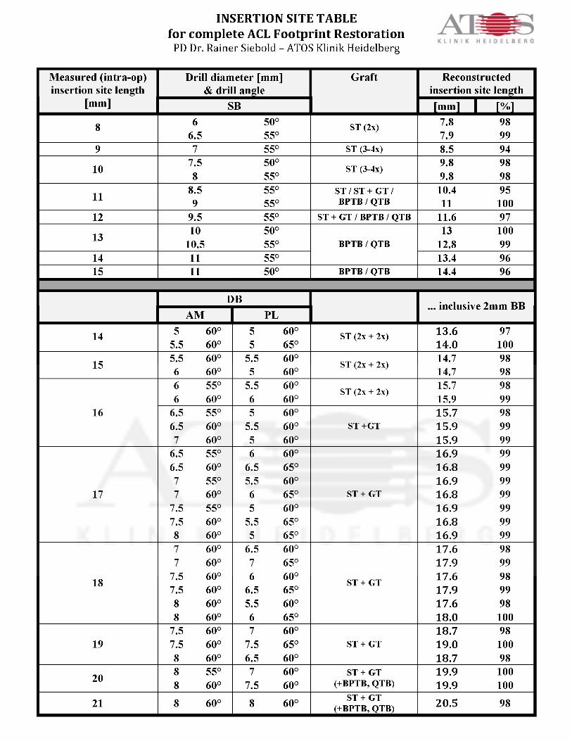
size of the ACL insertion sites. An “insertion site table” with guidelines for graft sizes and 21
drill angles was designed to match the surgical technique to the individual ACL insertion sites 22
of the patient. 23
Guidelines for Single Bundle and Double Bundle ACL Reconstruction 24
The surgically restored ISA of the ACL is defined by the width and the length of the oval 25
bone tunnel outlet(s), which is a function of the drill (graft) diameter and drill angle. The 26
average width of the native tibial and femoral insertion sites is between 9 - 11 mm. As this 27
2
range is rather small it may sufficiently reconstructed by the width of the tunnel diameters 28
during SB or DB ACL reconstruction in the majority of patients. However, big individual 29
variations do exist for the long axis of the tibial ACL insertion site in anterior-posterior 30
direction and for the long axis of the femoral insertion site in superior-inferior direction. The 31
surgically relevant range is reported to be between 9 - 21 mm on the tibia and between 11 - 21 32
mm on the femur. 33
Insertion site table 34
The “insertion site table” (Table 1) presents guidelines for SB and DB ACL reconstruction 35
based on the concept of “complete footprint restoration”. The length of the individual tibial 36
insertion sites (first column) is matched to an individual drill (graft) diameter and drill angle 37
(second column). Different grafts (third column) may be favourable depending on the size 38
of the recommended drill diameters and individual patient requirements, e.g. kneeling 39
profession, etc. The oval length of each articular bone tunnel outlet was calculated according 40
to the formula: drill size divided by sin ! based on a parallel alignment of the long axis to the 41
sagittal plane from anterior to posterior (Table 1). Oblique drilling directions to the sagittal 42
plane were not considered, as this complex the calculation significantly and may not play a 43
significant role. The surgically restored insertion site length (last column Table 1) is 44
displayed in milimeters and percentage of the native insertion site length (Table 1). To clarify 45
the concept and to avoid overdrilling of the insertion site length the calculated numbers are 46
given in millimeters with decimals. This accuracy cannot be achieved during drilling. 47
In contrast to the “classical” order of surgical steps during ACL reconstruction the concept 48
makes it necessary to first measure the length of the tibial ACL insertion site with a ruler 49
from anterior to posterior. The drill diameter and -angle as well as the surgical technique 50
(SB/DB) are assessed from the “insertion site table”. Then the diameter of the graft is 51
prepared according to the defined drill diameter and the ACL reconstruction is completed 52
respectively (Table 1). 53

3
According to our calculations a short tibial ACL insertion site between 8 - 13 mm may be 54
restored to more than 95% by an individually matched SB technique (Table 1). However, an 55
intermediate insertion site length of 14 - 15 mm is more critical to be reconstructed, as this 56
length needs large SB bone tunnels of 10 - 11 mm (Table 1). To increase the reconstructed 57
insertion site length even more, smaller drill angles as low as 45° may be used to create a 58
longer oval of the bone tunnel outlet. However, a long insertion site of 16 mm or more 59
cannot be completely reconstructed by one SB bone tunnel (Table 1) and consequently the 60
deficit of non-reconstructed ISA increase significantly with larger insertion sites. These are 61
the patients, which may have the highest biomechanical and clinical benefit from a DB 62
procedure as the reconstructed area is significantly larger than with a SB procedure. 63
Conclusion 64
The new concept of complete footprint restoration aims to maximize the reconstructed ACL 65
insertion site areas to achieve an optimized functional outcome. An “insertion site table” was 66
calculated for the surgeon, which defines drill diameters and drill angles as well as indications 67
for SB and DB reconstruction depending on the length of the tibial insertion site. In this 68
concept the DB technique is only considered as a surgical tool for large footprints and may 69
not be indicated for smaller insertion sites. 70
71
From: Siebold R. The concept of complete footprint restoration with guidelines for single- and double-bundle ACL reconstruction. 72 Knee Surg Sports Traumatol Arthrosc. 2011 Jan 11. {Epub ahead of print} 73
74
Fig. 1: Insertion Site Table (see page 4) 75
Recommendations for anatomical ACL footprint reconstruction to maximize the restored 76
insertion site area. ST semitendinosus 2x doubled, 3x trippled, 4x quadrupled, GT: gracilis 77
tendon, BPTB: bone patella bone tendon, QTB: quadriceps tendon., BB: bone bridge between 78
AM and PL. 79
80