SYEN 3330 Digital Systems
25
SYEN 3330 Digital Systems Jung H. Kim Chapter 4-1 1 SYEN 3330 Digital Systems Chapter 4 -Part 1
-
Upload
mckenzie-english -
Category
Documents
-
view
33 -
download
2
description
SYEN 3330 Digital Systems. Chapter 4 -Part 1. Functional Block: Decoders. 2-to-4 Line Decoder. 2-to-4 Line Demultiplexer. Example: 74F138 Demultiplexer. Note: This "Truth Table" uses the "x" to mean "this could be either 0 or 1". Thus, it "compacts" some of 2 6 = 64 lines. - PowerPoint PPT Presentation
Transcript of SYEN 3330 Digital Systems
SYEN 3330 Digital Systems Jung H. Kim Chapter 4-1 1
SYEN 3330 Digital Systems
Chapter 4 -Part 1
SYEN 3330 Digital Systems Chapter4-1 Page 2
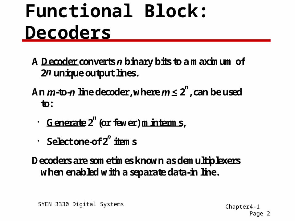
Functional Block: Decoders
A Decoder converts n binary bits to a maximum of2n unique output lines.
An m-to-n line decoder, where m < 2n, can be used
to:
Generate 2n (or fewer) minterms,
Select one-of 2n items
Decoders are sometimes known as demultiplexerswhen enabled with a separate data-in line.
SYEN 3330 Digital Systems Chapter4-1 Page 3
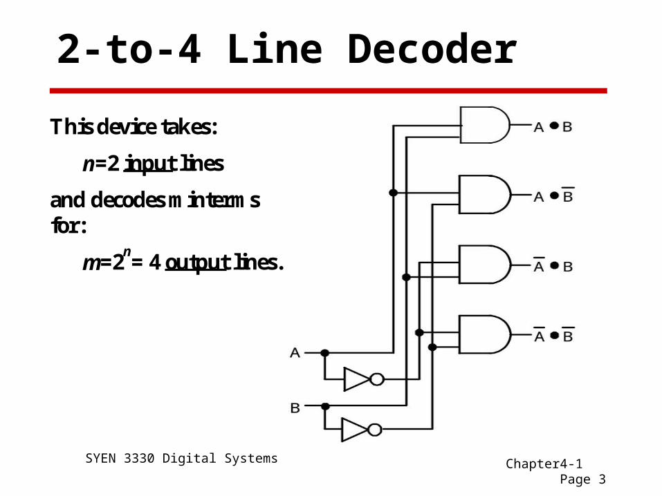
2-to-4 Line Decoder
This device takes:
n=2 input lines
and decodes mintermsfor:
m=2n= 4 output lines.
SYEN 3330 Digital Systems Chapter4-1 Page 4
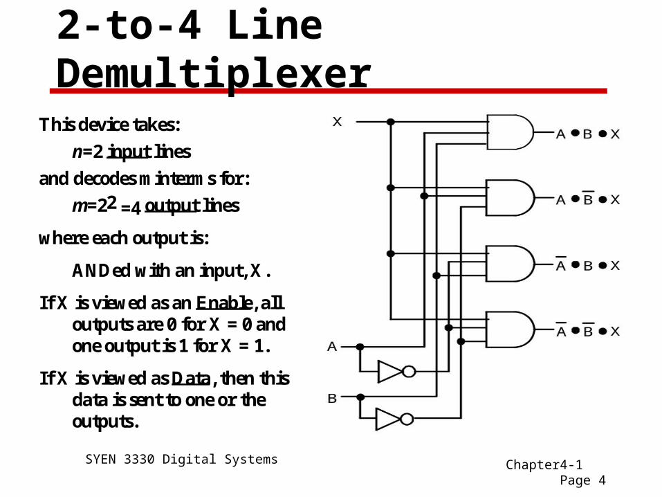
2-to-4 Line Demultiplexer
This device takes:
n=2 input lines
and decodes minterms for:
m=22 =4 output lines
where each output is:
ANDed with an input, X.
If X is viewed as an Enable, alloutputs are 0 for X = 0 andone output is 1 for X = 1.
If X is viewed as Data, then thisdata is sent to one or theoutputs.
SYEN 3330 Digital Systems Chapter4-1 Page 5
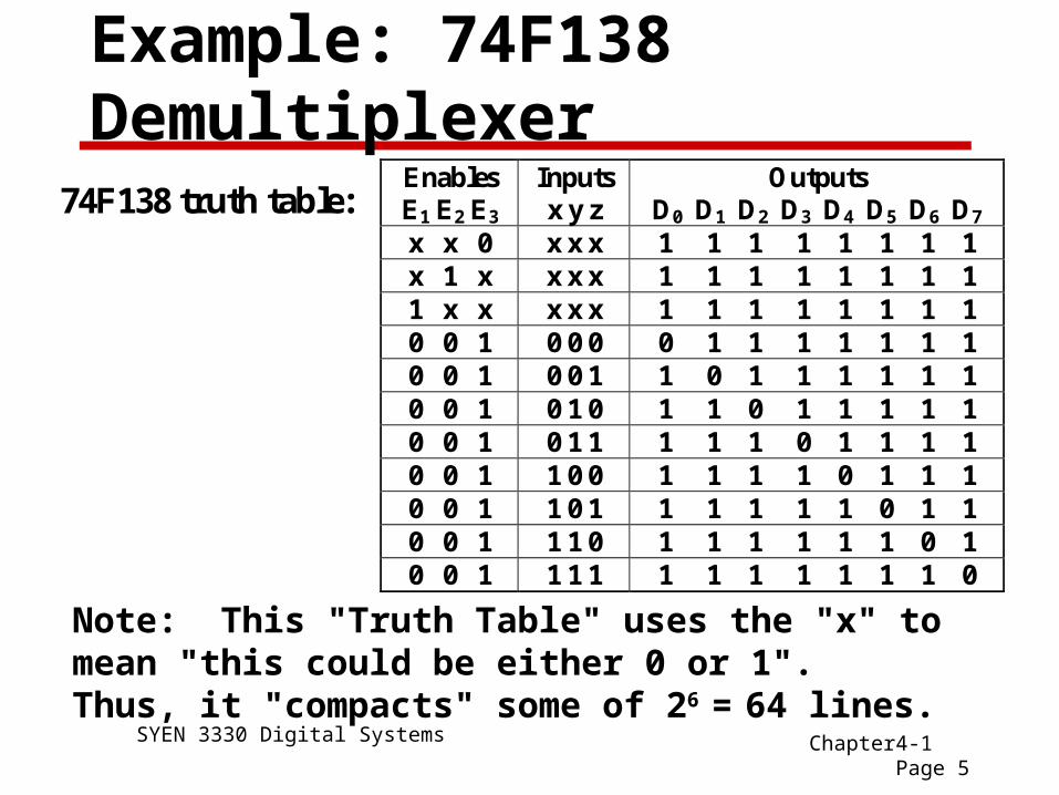
Example: 74F138 DemultiplexerEnables E1 E2 E3
Inputs x y z
Outputs D0 D1 D2 D3 D4 D5 D6 D7
x x 0 x x x 1 1 1 1 1 1 1 1 x 1 x x x x 1 1 1 1 1 1 1 1 1 x x x x x 1 1 1 1 1 1 1 1 0 0 1 0 0 0 0 1 1 1 1 1 1 1 0 0 1 0 0 1 1 0 1 1 1 1 1 1 0 0 1 0 1 0 1 1 0 1 1 1 1 1 0 0 1 0 1 1 1 1 1 0 1 1 1 1 0 0 1 1 0 0 1 1 1 1 0 1 1 1 0 0 1 1 0 1 1 1 1 1 1 0 1 1 0 0 1 1 1 0 1 1 1 1 1 1 0 1 0 0 1 1 1 1 1 1 1 1 1 1 1 0
Note: This "Truth Table" uses the "x" to mean "this could be either 0 or 1". Thus, it "compacts" some of 26
= 64 lines.
74F138 truth table:
SYEN 3330 Digital Systems Chapter4-1 Page 6
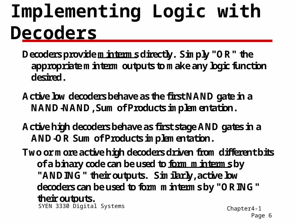
Implementing Logic with Decoders
Decoders provide minterms directly. Simply "OR" theappropriate minterm outputs to make any logic functiondesired.
Active low decoders behave as the first NAND gate in aNAND-NAND, Sum of Products implementation.
Active high decoders behave as first stage AND gates in aAND-OR Sum of Products implementation.
Two or more active high decoders driven from different bitsof a binary code can be used to form minterms by"ANDING" their outputs. Similarly, active lowdecoders can be used to form minterms by "ORING"their outputs.

SYEN 3330 Digital Systems Chapter4-1 Page 7
Example 1: F(A,B) = m(0,3)
For this we use a 2-to-4line decoder and summinterms 0 and 3 with anOR gate:
B
A
F
m0
m3

SYEN 3330 Digital Systems Chapter4-1 Page 8
Example 1: F(X,Y,Z) = m(0,3,5,6)
SYEN 3330 Digital Systems Chapter4-1 Page 9
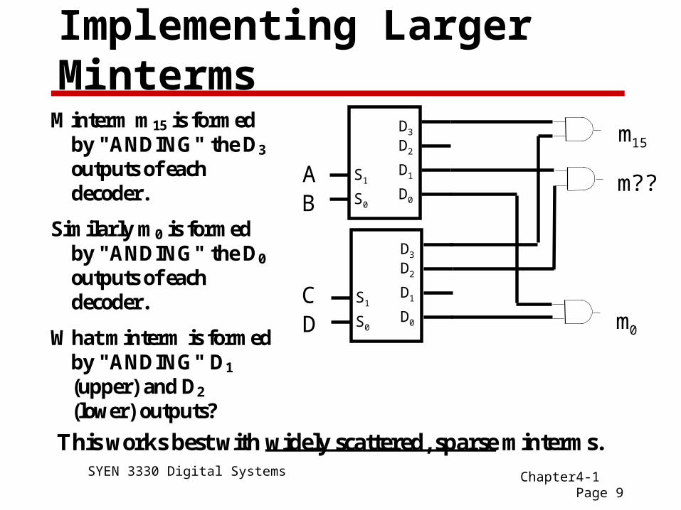
Implementing Larger Minterms
Minterm m15 is formed by "ANDING" the D3 outputs of each decoder.
Similarly m0 is formed by "ANDING" the D0 outputs of each decoder.
What minterm is formed by "ANDING" D1 (upper) and D2
(lower) outputs? This works best with widely scattered, sparse minterms.
S0
S1
D3
D2
D1
D0
S0
S1
D3
D2
D1
D0
AB
CD
m15
m0
m??
SYEN 3330 Digital Systems Chapter4-1 Page 10
Functional Block: Encoders Encoders perform the "inverse" operation of decoders,
taking a code in one format and encoding it into another format.
Many encoders consist of just OR gates. For example an 8-to-3 binary encoder consists of three 4-input OR gates, OR2 ,OR1 and OR0. Input Ii, i = 0,…,7 is connected to an input on ORj if the binary representation of i has a 1 in position j.
A priority encoder is used to generate a code for the "most significant" bit set in a string of bits. This can be used to find the first one in a word, or to select external events in priority order. An example of a MSI priority encoder is the 74F148, 8 line to 3 line priority encoder. It can be cascaded to encode higher numbers of bits.
SYEN 3330 Digital Systems Chapter4-1 Page 11
Review: Decoders and Encoders
A Decoder converts n binary bits to a maximum of 2n
unique output lines.
Decoders are sometimes know as demultiplexers when enabled with a separate data-in line.
Decoders implement minterms directly.
Use a decoder and an OR gate to form Sum-of-Minterms directly.
Encoders perform the "inverse" operation of decoders, taking a code in one format and encoding it into another format.
SYEN 3330 Digital Systems Chapter4-1 Page 12
Multiplexers
A Multiplexer (MUX) is another common functionalblock.
A Multiplexer uses n binary select bits to choose from amaximum of 2n unique input lines.
Like a decoder, it decodes minterms internally.
Unlike a decoder, it has only one output line.
The decoded minterms are used to select data from one ofup to 2n unique data input lines.
The output of the multiplexer is the data input whoseindex is specified by the n bit code.
SYEN 3330 Digital Systems Chapter4-1 Page 13
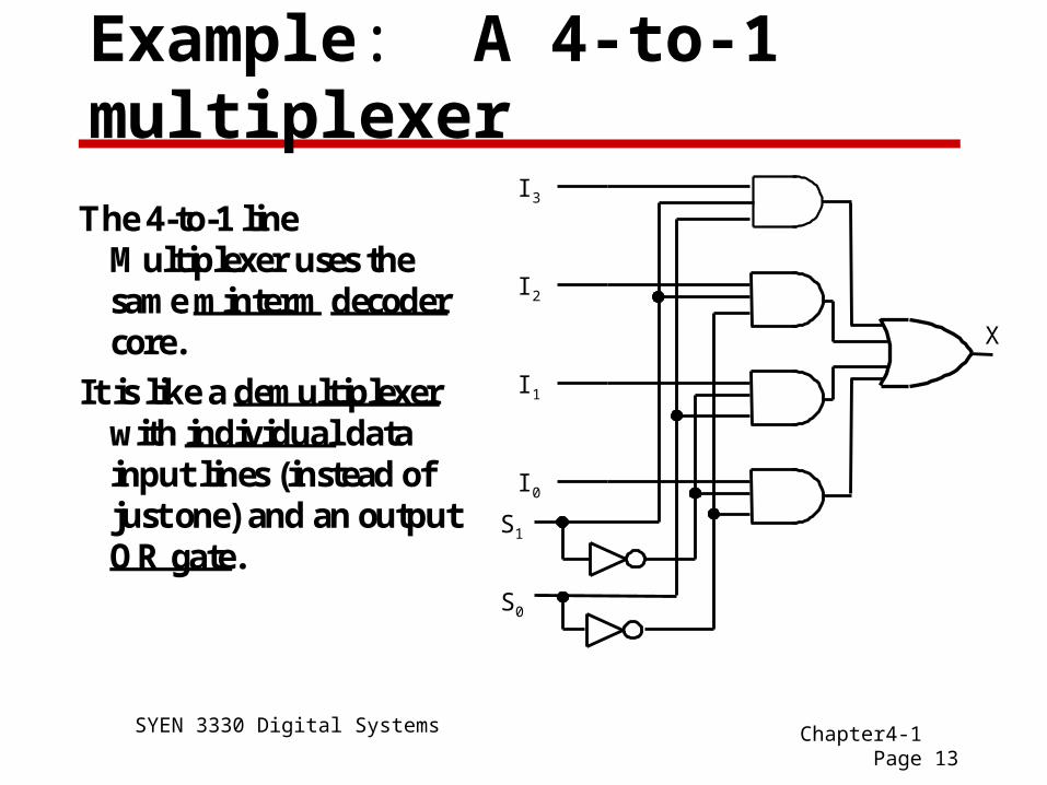
Example: A 4-to-1 multiplexer
The 4-to-1 lineMultiplexer uses thesame minterm decodercore.
It is like a demultiplexerwith individual datainput lines (instead ofjust one) and an outputOR gate.
S0
S1
I3
I2
I1
I0
X
SYEN 3330 Digital Systems Chapter4-1 Page 14
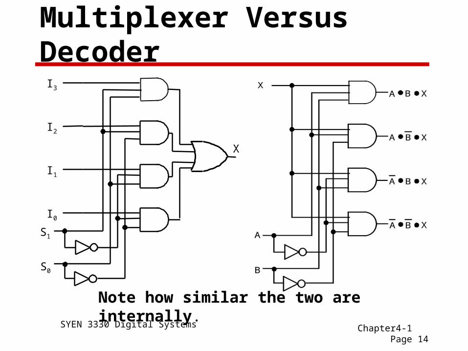
Multiplexer Versus Decoder
Note how similar the two are internally.
S0
S1
I3
I2
I1
I0
X

SYEN 3330 Digital Systems Chapter4-1 Page 15
Functions with Multiplexers
It is possible to implement any Boolean function of nvariables with a 2n input multiplexer.
Simply tie each input to the "1" or "0" line as desired.
It is also possible to implement any n+1 variable functionwith a 2n multiplexer. Simply use the (n+1)st variable intrue or complement form depending upon what the truthtable requires.
A Boolean function of more than n variables can bepartitioned into several easily implemented sub-functionsdefined on a subset of the variables.
The multiplexer will then select among these sub-functions.
SYEN 3330 Digital Systems Chapter4-1 Page 16
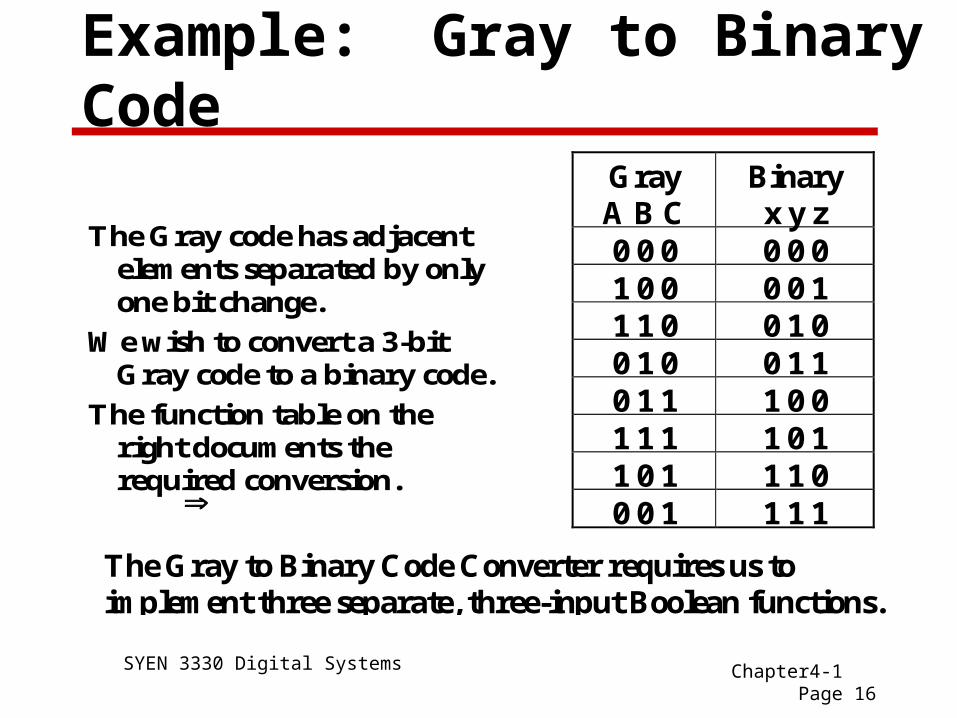
Example: Gray to Binary Code
The Gray code has adjacentelements separated by onlyone bit change.
We wish to convert a 3-bitGray code to a binary code.
The function table on theright documents therequired conversion.
GrayA B C
Binaryx y z
0 0 0 0 0 01 0 0 0 0 11 1 0 0 1 00 1 0 0 1 10 1 1 1 0 01 1 1 1 0 11 0 1 1 1 00 0 1 1 1 1
The Gray to Binary Code Converter requires us toimplement three separate, three-input Boolean functions.
SYEN 3330 Digital Systems Chapter4-1 Page 17
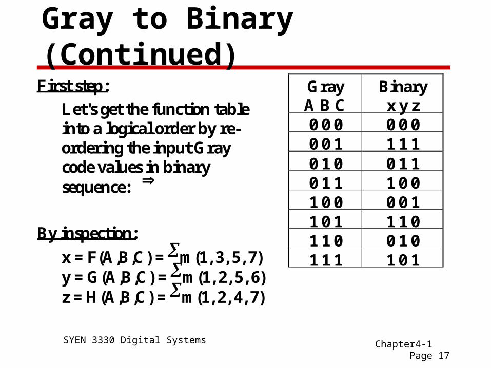
Gray to Binary (Continued)
First step:
Let's get the function tableinto a logical order by re-ordering the input Graycode values in binarysequence:
GrayA B C
Binaryx y z
0 0 0 0 0 00 0 1 1 1 10 1 0 0 1 10 1 1 1 0 01 0 0 0 0 11 0 1 1 1 01 1 0 0 1 01 1 1 1 0 1
By inspection:
x = F(A,B,C) = m(1, 3, 5, 7)y = G(A,B,C) = m(1, 2, 5, 6)z = H(A,B,C) = m(1, 2, 4, 7)

SYEN 3330 Digital Systems Chapter4-1 Page 18
Gray to Binary (Continued)
A
B
C
0 1 23
4 5 67 A
B
C
0 1 23
4 5 67
A
B
C
0 1 23
4 5 67
X Y
Z
1 1
1
1
1 11
1 1
1
11
Note:
x(A,B,C) = C, is an easy function toimplement. (No logic gates needed!)
Function y(A,B,C) = B'C + B'C is abit harder to implement.
Function z(A,B,C) looks familiar.What is it?
The K-Maps
SYEN 3330 Digital Systems Chapter4-1 Page 19
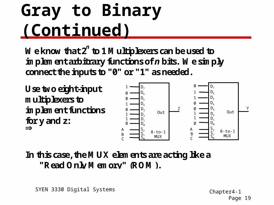
Gray to Binary (Continued)
We know that 2n to 1 Multiplexers can be used to
implement arbitrary functions of n bits. We simply connect the inputs to "0" or "1" as needed.
In this case, the MUX elements are acting like a"Read Only Memory" (ROM).
Use two eight-inputmultiplexers toimplement functionsfor y and z: A
B
D3
D2
D1D0
S1S0
S2
D4
D5
D6
D7
Out
C
AB
Out
C
11
1
1
11
110
0
0
0
0
00
0
Z Y
8-to-1MUX
8-to-1MUX
D3
D2
D1D0
S1S0
S2
D4
D5
D6
D7

SYEN 3330 Digital Systems Chapter4-1 Page 20
Other MUX Implementations
We can also use two 4-to-1 MUX blocks and implement y andz.
Suppose we factor out A and use B and C as the select inputsto the multiplexers
A
C
BY
1
1
1
1
00 01 1011
D0 D1 D2D3
0
0
0
0
A
C
BZ
0
1
0
1
00 01 1011
D0 D1 D2D3
0
11
0
A AA A
SYEN 3330 Digital Systems Chapter4-1 Page 21
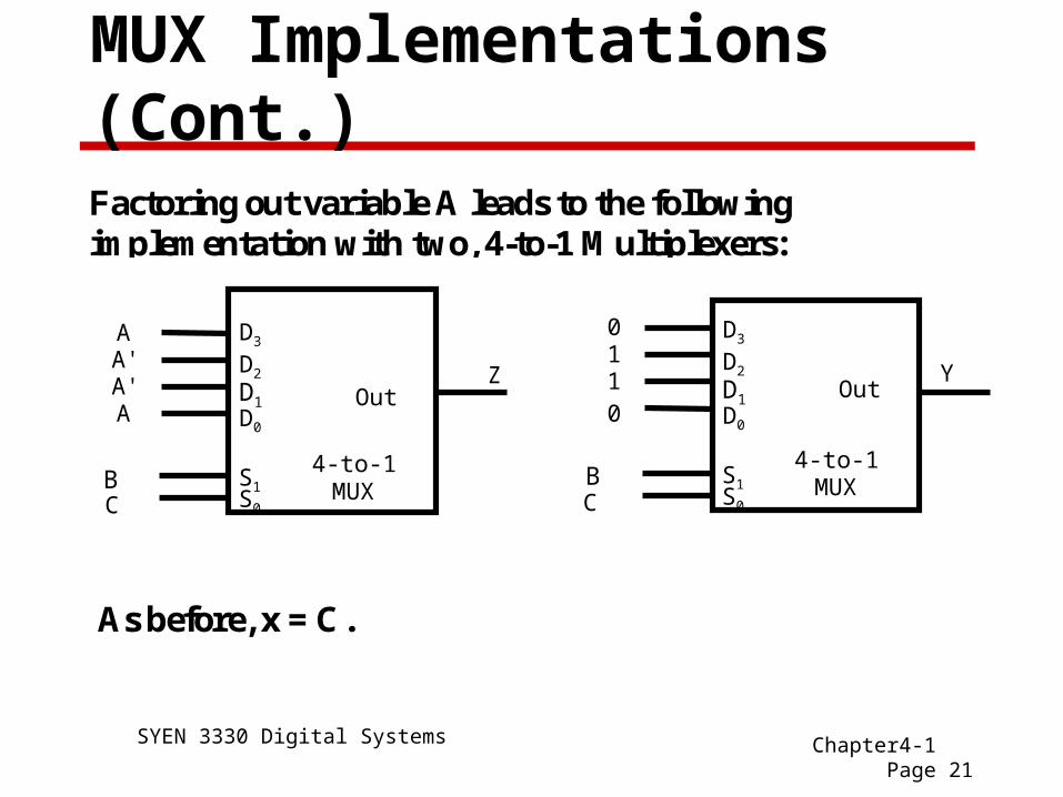
MUX Implementations (Cont.)
Factoring out variable A leads to the followingimplementation with two, 4-to-1 Multiplexers:
As before, x = C.
D3
D2
D1D0
S1S0
B
Out
C
D3
D2
D1D0
S1S0
B
Out
C
A'A'
11
A
A
0
0
Z Y
4-to-1MUX
4-to-1MUX
SYEN 3330 Digital Systems Chapter4-1 Page 22
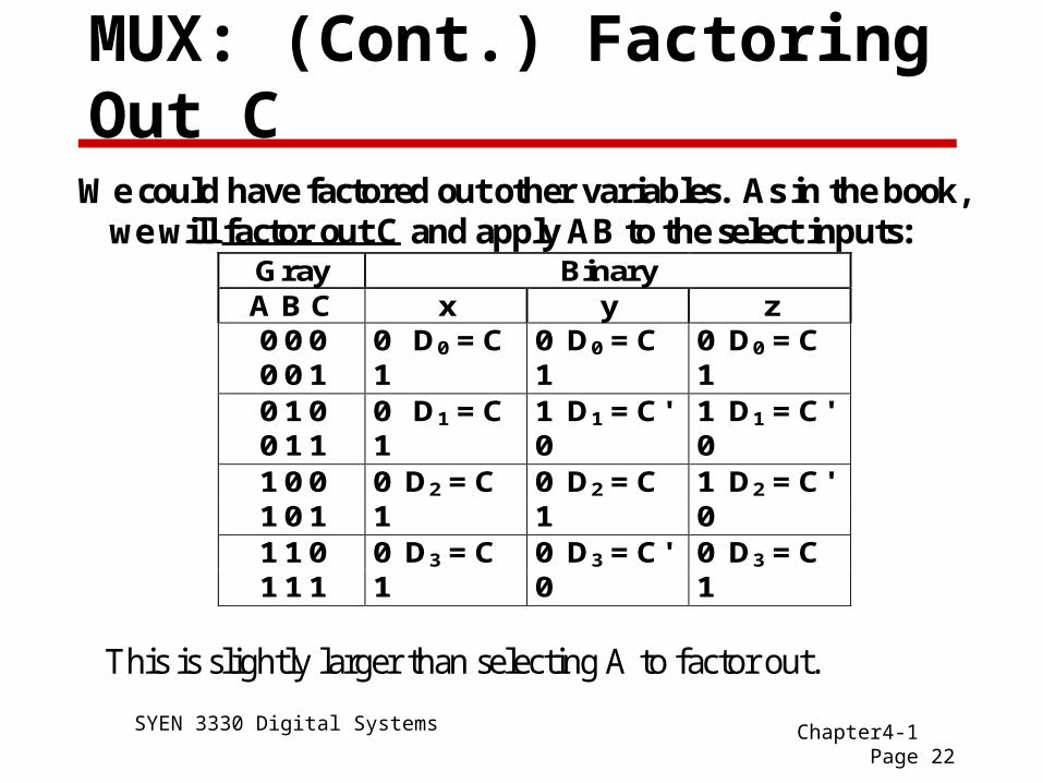
MUX: (Cont.) Factoring Out C
We could have factored out other variables. As in the book,we will factor out C and apply AB to the select inputs:
Gray Binary A B C x y z 0 0 0 0 D0 = C 0 D0 = C 0 D0 = C 0 0 1 1 1 1 0 1 0 0 D1 = C 1 D1 = C' 1 D1 = C' 0 1 1 1 0 0 1 0 0 0 D2 = C 0 D2 = C 1 D2 = C' 1 0 1 1 1 0 1 1 0 0 D3 = C 0 D3 = C' 0 D3 = C 1 1 1 1 0 1
This is slightly larger than selecting A to factor out.

SYEN 3330 Digital Systems Chapter4-1 Page 23
MUX: (Cont.) Factoring out B
Gray BinaryA B C x y z0 0 0 0 x = "0" 0 y = B 0 z = B0 1 0 0 1 10 0 1 1 x = "1" 1 y = B' 1 z = B'0 1 1 1 0 01 0 0 0 x = "0" 0 y = B 1 z = B'1 1 0 0 1 01 0 1 1 x = "1" 1 y = B' 0 z = B1 1 1 1 0 1
Note: We re-arranged the table (fixing A and C andvarying B from 0 to 1 in each cell) to simplify thisprocedure. It still looks like factoring A was better.
SYEN 3330 Digital Systems Chapter4-1 Page 24
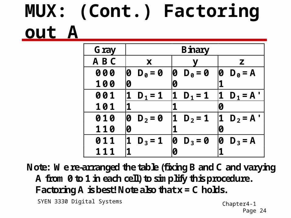
MUX: (Cont.) Factoring out A
Gray Binary A B C x y z 0 0 0 0 D0 = 0 0 D0 = 0 0 D0 = A 1 0 0 0 0 1 0 0 1 1 D1 = 1 1 D1 = 1 1 D1 = A' 1 0 1 1 1 0 0 1 0 0 D2 = 0 1 D2 = 1 1 D2 = A' 1 1 0 0 1 0 0 1 1 1 D3 = 1 0 D3 = 0 0 D3 = A 1 1 1 1 0 1
Note: We re-arranged the table (fixing B and C and varyingA from 0 to 1 in each cell) to simplify this procedure.Factoring A is best! Note also that x = C holds.
SYEN 3330 Digital Systems Chapter4-1 Page 25
Summary
• Know the functions performed by the following functional blocks: Decoders Demultiplexers Encoders Multiplexers
• Know how to implement Boolean functions using: Multiplexers Decoders