
SWS ESPC 0003 B-02 - uClibc
42
ARM ELF SWS ESPC 0003 B-02 Page 1 of 42 ARM ELF Development Systems Business Unit Engineering Software Group Document number: SWS ESPC 0003 B-02 Date of Issue: 8 June, 2001 Author: - Authorized by: © Copyright ARM Limited 1998, 2000. All rights reserved. Section 3 © Copyright Tool Interface Standards Committee 1995. Abstract This specification defines the ARM-specific features of Executable and Linking Format (ELF). Keywords ARM ELF, ELF, ELF relocation types, Executable and Linking Format (ELF) Distribution list Name Function Name Function
Transcript of SWS ESPC 0003 B-02 - uClibc

ARM ELF
SWS ESPC 0003 B-02 Page 1 of 42
ARM ELFDevelopment Systems Business Unit
Engineering Software Group
Document number: SWS ESPC 0003 B-02
Date of Issue: 8 June, 2001
Author: -
Authorized by:
© Copyright ARM Limited 1998, 2000. All rights reserved.
Section 3 © Copyright Tool Interface Standards Committee 1995.
AbstractThis specification defines the ARM-specific features of Executable and Linking Format (ELF).
KeywordsARM ELF, ELF, ELF relocation types, Executable and Linking Format (ELF)
Distribution listName Function Name Function

ARM ELF
SWS ESPC 0003 B-02 Page 2 of 42
Contents
1 ABOUT THIS DOCUMENT 4
1.1 Change control 41.1.1 Current status and anticipated changes 41.1.2 Change history 4
1.2 References 4
1.3 Terms and abbreviations 4
2 SCOPE 5
3 GENERIC 32-BIT ELF 6
3.1 Introduction 63.1.1 File Format 63.1.2 Data Representation 73.1.3 Character Representations 7
3.2 ELF Header 83.2.1 ELF Identification 10
3.3 Sections 123.3.1 Special Sections 16
3.4 String Table 18
3.5 Symbol Table 193.5.1 Symbol Values 21
3.6 Relocation 21
3.7 Program view 223.7.1 Program Header 223.7.2 Note Section 243.7.3 Program Loading 253.7.4 Dynamic Linking 25
3.8 Special Sections Names 26
3.9 Pre-existing Extensions 26
4 ARM- AND THUMB-SPECIFIC DEFINITIONS 27
4.1 ELF header 274.1.1 Entry points 28
4.2 Section names 28

ARM ELF
SWS ESPC 0003 B-02 Page 3 of 42
4.3 Section headers 294.3.1 Common sections 294.3.2 Section alignment 294.3.3 Link and info fields 30
4.4 Symbols 304.4.1 Symbol value 304.4.2 Symbol size 304.4.3 Weak symbols 304.4.4 Symbol names 314.4.5 Sub-class and super-class symbols 314.4.6 Function address constants and pointers to code 314.4.7 Mapping and tagging symbols 31
4.4.7.1 Mapping symbols 324.4.7.2 Tagging symbols 32
4.4.8 Symbol table order 324.4.9 Dynamic symbol table entries 33
4.5 Relocation types 334.5.1 Dynamic relocation types 364.5.2 Multiple relocation 374.5.3 Field extraction and insertion 374.5.4 Relocations that depend on the type of the target location 38
4.6 Program headers 39
4.7 Dynamic linking and relocation 404.7.1 The dynamic segment 404.7.2 The dynamic segment program header 404.7.3 The dynamic section 41
DT_SYMBOLIC 414.7.4 The hash table section 42

ARM ELF
SWS ESPC 0003 B-02 Page 4 of 42
1 ABOUT THIS DOCUMENT
1.1 Change control
1.1.1 Current status and anticipated changes
Issue A-06 of this specification is the first public release.
Issue A-08 is the ADS-1.0/1.0.1 release.
Issue B-01 is the ADS-1.1 release.
1.1.2 Change history
Issue Date By Change
A-06 5 November 1998 - Editorial changes following review of final internal DRAFT.
A-07 17 September 1999 - Added definitions of PF_xx flags, PF_ARM_xxx flags, $r, $p, and theEF_ARM_EABIxxx version number. Updated the definition of commonsection, added descriptions of $Super$$ and $Sub$$ and clarifiedtype-dependent relocation.
A-08 22 September 1999 - Removed $r—inadequate for the purpose.
B-01 August-October 2000 - Simplified and clarified the presentation. Completed the description ofshared objects and re-locatable executables.
B-02 8 June 2001 - Repaired the broken hyperlink to TIS ELF.
1.2 References
This document refers to the following document and reproduces book 1 of it as section 3, below.
Ref Doc No Author(s) Title
TIS-ELF http://www.x86.org/ftp/manuals/tools/elf.pdf Tool Interface Standards(TIS) Committee
Executable and Linking Format(ELF) Specification (version 1.2)
1.3 Terms and abbreviations
This document uses the following terms and abbreviations.
Term Meaning
TIS Tool Interface Standards
ELF Executable and Linking Format
(E)ABI (Embedded) Applications Binary Interface
OS Operating System

ARM ELF
SWS ESPC 0003 B-02 Page 5 of 42
2 SCOPE
This specification defines ARM Executable and Linking Format (ARM ELF). It follows the essential structure of theTool Interface Standards (TIS) Committee’s version 1.2 specification of ELF (TIS-ELF). TIS-ELF is divided intothree major sections that TIS-ELF calls books:
� Book 1 defines generic, 32-bit ELF. All users of 32-bit ELF use the definitions given in book 1. Section 3 ofthis specification reproduces the content of book 1 of TIS-ELF (Copyright Tool Interface Standards Committee1995), with a few editorial corrections and clarifications, but no intentional change of content.
� Book 2 defines processor specifics, the definitions used by all users of ELF for a given processor (in the caseof TIS-ELF, for the Intel x86 architecture).
� Book 3 defines operating system specifics (in the case of TIS-ELF, for Unix System V.4 for x86).
Section 4 of this specification covers the material of books 2 and 3 of TIS-ELF. It includes:
� ARM- and Thumb-specific definitions needed by all users of ARM ELF.
� ARM- and Thumb-specific definitions relating to the ARM Embedded Applications Binary Interface (EABI).
The ARM EABI underlies many ARM- and Thumb-based operating environments that follow the single address-space model.
Some operating systems—especially those founded on multiple virtual address spaces—define their ownconventions for using ARM ELF—especially in relation to shared objects and dynamic linking. These OS-specificdefinitions extend section 4 of this specification.

ARM ELF
SWS ESPC 0003 B-02 Page 6 of 42
3 GENERIC 32-BIT ELF
3.1 Introduction
Section 3 of this specification describes the object file format called ELF (Executable and Linking Format). Thereare three main types of object files:
� A re-locatable file holds code and data suitable for linking with other object files to create an executable or ashared object file.
� An executable file holds a program suitable for execution.
� A shared object file holds code and data suitable for linking in two contexts. First, the link editor may process itwith other re-locatable and shared object files to create another object file. Second, the dynamic linkercombines it with an executable file and other shared objects to create a process image.
Created by an assembler or compiler and link editor, object files are binary representations of programs intendedto execute directly on a processor. Programs that require other abstract machines are excluded.
After the introductory material, this section focuses on the file format and how it pertains to building programs.Subsections 3.7 onwards describe those parts of the object file containing the information necessary to execute aprogram.
3.1.1 File Format
Object files participate in program linking (building a program) and program execution (running a program). Forconvenience and efficiency, the object file format provides parallel views of a file’s contents, reflecting the differingneeds of these activities. Figure 3-1 below shows an object file’s organization.
Figure 3-1, Object file format
Linking View Execution View
ELF Header ELF Header
Program Header Tableoptional
Program Header Table
Section 1
…
Segment 1
Section n
…
Segment 2
… …
Section Header Table Section Header Tableoptional
An ELF header resides at the beginning and holds a road map describing the file’s organization. Sections hold thebulk of object file information for the linking view: instructions, data, symbol table, relocation information, and soon. Descriptions of special sections appear later in this section. Subsections 3.7 onwards describe segments andthe program execution view of the file.

ARM ELF
SWS ESPC 0003 B-02 Page 7 of 42
A program header table, if present, tells the system how to create a process image. Files used to build a processimage (execute a program) must have a program header table; re-locatable files do not need one. A sectionheader table contains information describing the file’s sections. Every section has an entry in the table; each entrygives information such as the section name, the section size, and so on. Files used during linking must have asection header table; other object files may or may not have one.
Note Although the figure shows the program header table immediately after the ELF header, and the sectionheader table following the sections, actual files may differ. Moreover, sections and segments have nospecified order. Only the ELF header has a fixed position in the file.
3.1.2 Data Representation
As described here, the object file format supports various processors with 8-bit bytes and 32-bit architectures.Nevertheless, it is intended to be extensible to larger (or smaller) architectures. Object files therefore representsome control data with a machine-independent format, making it possible to identify object files and interpret theircontents in a common way. Remaining data in an object file use the encoding of the target processor, regardlessof the machine on which the file was created.
Figure 3-2, 32-Bit Data Types
Name Size Alignment Purpose
Elf32_Addr 4 4 Unsigned program address
Elf32_Half 2 2 Unsigned medium integer
Elf32_Off 4 4 Unsigned file offset
Elf32_Sword 4 4 Signed large integer
Elf32_Word 4 4 Unsigned large integer
unsigned char 1 1 Unsigned small integer
All data structures that the object file format defines follow the natural size and alignment guidelines for therelevant class. If necessary, data structures contain explicit padding to ensure 4-byte alignment for 4-byte objects,to force structure sizes to a multiple of 4, and so on. Data also have suitable alignment from the beginning of thefile. Thus, for example, a structure containing an Elf32_Addr member will be aligned on a 4-byte boundary withinthe file.
For portability reasons, ELF uses no bit fields.
3.1.3 Character Representations
This section describes the default ELF character representation and defines the standard character set used forexternal files that should be portable among systems. Several external file formats represent control informationwith characters. These single-byte characters use the 7-bit ASCII character set. In other words, when the ELFinterface document mentions character constants, such as, ‘/’ or ‘\n’ their numerical values should follow the 7-bitASCII guidelines. For the previous character constants, the single-byte values would be 47 and 10, respectively.
Character values outside the range of 0 to 127 may occupy one or more bytes, according to the characterencoding. Applications can control their own character sets, using different character set extensions for differentlanguages as appropriate. Although TIS-conformance does not restrict the character sets, they generally shouldfollow some simple guidelines:
� Character values between 0 and 127 should correspond to the 7-bit ASCII code. That is, character sets withencodings above 127 should include the 7-bit ASCII code as a subset.

ARM ELF
SWS ESPC 0003 B-02 Page 8 of 42
� Multi-byte character encodings with values above 127 should contain only bytes with values outside the rangeof 0 to 127. That is, a character set that uses more than one byte per character should not embed a byteresembling a 7-bit ASCII character within a multi-byte, non-ASCII character.
� Multi-byte characters should be self-identifying. That allows, for example, any multi-byte character to beinserted between any pair of multi-byte characters, without changing the characters’ interpretations.
These cautions are particularly relevant for multilingual applications.
Note There are naming conventions for ELF constants that have processor ranges specified. Names such asDT_, PT_, for processor specific extensions, incorporate the name of the processor: DT_M32_SPECIAL,for example. However, pre-existing processor extensions not using this convention will be supported.
Pre-existing Extensions
DT_JMP_REL
3.2 ELF Header
Some object file control structures can grow, because the ELF header contains their actual sizes. If the object fileformat changes, a program may encounter control structures that are larger or smaller than expected. Programsmight therefore ignore extra information. The treatment of missing information depends on context and will bespecified when and if extensions are defined.
Figure 3-3, ELF Header
#define EI_NIDENT 16
typedef struct { unsigned char e_ident[EI_NIDENT]; Elf32_Half e_type; Elf32_Half e_machine; Elf32_Word e_version; Elf32_Addr e_entry; Elf32_Off e_phoff; Elf32_Off e_shoff; Elf32_Word e_flags; Elf32_Half e_ehsize; Elf32_Half e_phentsize; Elf32_Half e_phnum; Elf32_Half e_shentsize; Elf32_Half e_shnum; Elf32_Half e_shstrndx;} Elf32_Ehdr;
e_ident—The initial bytes mark the file as an object file and provide machine-independent data with which todecode and interpret the file’s contents. Complete descriptions appear below, in section 3.2.1, ELF Identification.
E_type—This member identifies the object file type.
Name Value Meaning
ET_NONE 0 No file type
ET_REL 1 Re-locatable file
ET_EXEC 2 Executable file
ET_DYN 3 Shared object file

ARM ELF
SWS ESPC 0003 B-02 Page 9 of 42
E_type (continued)
Name Value Meaning
ET_CORE 4 Core file
ET_LOPROC 0xff00 Processor-specific
ET_HIPROC 0xffff Processor-specific
Although the core file contents are unspecified, type ET_CORE is reserved to mark the file type. Values fromET_LOPROC through ET_HIPROC (inclusive) are reserved for processor-specific semantics. Other values arereserved and will be assigned to new object file types as necessary.
E_machine—This member’s value specifies the required architecture for an individual file.
Name Value Meaning
EM_NONE 0 No machine
EM_M32 1 AT&T WE 32100
EM_SPARC 2 SPARC
EM_386 3 Intel Architecture
EM_68K 4 Motorola 68000
EM_88K 5 Motorola 88000
EM_860 7 Intel 80860
EM_MIPS 8 MIPS RS3000 Big-Endian
EM_MIPS_RS4_BE 10 MIPS RS4000 Big-Endian
… … …
EM_ARM 40 ARM/Thumb Architecture
Other values are reserved and will be assigned to new machines as necessary. Processor-specific ELF namesuse the machine name to distinguish them. For example, the flags mentioned below use the prefix EF_; a flagnamed WIDGET for the EM_XYZ machine would be called EF_XYZ_WIDGET.
E_version—This member identifies the object file version.
Name Value Meaning
EV_NONE 0 Invalid version
EV_CURRENT 1 Current version
The value 1 signifies the original file format; extensions will create new versions with higher numbers. The value ofEV_CURRENT, though given as 1 above, will change as necessary to reflect the current version number.
E_entry—This member gives the virtual address to which the system first transfers control, thus starting theprocess. If the file has no associated entry point, this member holds zero.
E_phoff—This member holds the program header table’s file offset in bytes. If the file has no program headertable, this member holds zero.

ARM ELF
SWS ESPC 0003 B-02 Page 10 of 42
E_shoff—This member holds the section header table’s file offset in bytes. If the file has no section header table,this member holds zero.
E_flags—This member holds processor-specific flags associated with the file. Flag names take the formEF_machine_flag. See section 4.1, ELF header, for definitions of flag values.
E_ehsize—This member holds the ELF header’s size in bytes.
E_phentsize—This member holds the size in bytes of one entry in the file’s program header table; all entries arethe same size.
E_phnum—This member holds the number of entries in the program header table. Thus the product ofe_phentsize and e_phnum gives the table’s size in bytes. If a file has no program header table, e_phnumholds the value zero.
E_shentsize—This member holds a section header’s size in bytes. A section header is one entry in the sectionheader table; all entries are the same size.
E_shnum—This member holds the number of entries in the section header table. Thus the product ofe_shentsize and e_shnum gives the section header table’s size in bytes. If a file has no section headertable, e_shnum holds the value zero.
E_shstrndx—This member holds the section header table index of the entry associated with the section namestring table. If the file has no section name string table, this member holds the value SHN_UNDEF. See section3.3, Sections and section 3.4, String Table below for more information.
3.2.1 ELF Identification
As mentioned above, ELF provides an object file framework to support multiple processors, multiple dataencodings, and multiple classes of machines. To support this object file family, the initial bytes of the file specifyhow to interpret the file, independent of the processor on which the inquiry is made and independent of the file’sremaining contents.
The initial bytes of an ELF header (and an object file) correspond to the e_ident member.
Figure 3-4, e_ident[] Identification Indexes
Name Value Purpose
EI_MAG0 0 File identification
EI_MAG1 1 File identification
EI_MAG2 2 File identification
EI_MAG3 3 File identification
EI_CLASS 4 File class
EI_DATA 5 Data encoding
EI_VERSION 6 File version
EI_PAD 7 Start of padding bytes
EI_NIDENT 16 Size of e_ident[]
These indexes access bytes that hold the values defined in the following tables.

ARM ELF
SWS ESPC 0003 B-02 Page 11 of 42
EI_MAG0 to to to to EI_MAG3—A file’s first 4 bytes hold a magic number, identifying the file as an ELF object file.
Name Value Meaning
ELFMAG0 0x7f e_ident[EI_MAG0]
ELFMAG1 ASCII ’E’ e_ident[EI_MAG1]
ELFMAG2 ASCII ’L’ e_ident[EI_MAG2]
ELFMAG3 ASCII ’F’ e_ident[EI_MAG3]
EI_CLASS—The next byte, e_ident[EI_CLASS], identifies the file’s class, or capacity.
Name Value Meaning
ELFCLASSNONE 0 Invalid class
ELFCLASS32 1 32-bit objects
ELFCLASS64 2 64-bit objects
The file format is designed to be portable among machines of various sizes, without imposing the sizes of thelargest machine on the smallest. Class ELFCLASS32 supports machines with files and virtual address spaces upto 4 gigabytes; it uses the basic types defined above.
Class ELFCLASS64 is incomplete and refers to the 64-bit architectures. Its appearance here shows how theobject file may change. Other classes will be defined as necessary, with different basic types and sizes for objectfile data.
EI_DATA—Byte e_ident[EI_DATA]specifies the data encoding of all data1 in the object file. The followingencodings are currently defined.
Name Value Meaning
ELFDATANONE 0 Invalid data encoding
ELFDATA2LSB 1 See Data encodings ELFDATA2LSB, below
ELFDATA2MSB 2 See Data encodings ELFDATA2MSB, below
More information on these encodings appears below in Figure 3-5 and Figure 3-6. Other values are reserved andwill be assigned to new encodings as necessary.
EI_VERSION—Byte e_ident[EI_VERSION] specifies the ELF header version number. Currently, this valuemust be EV_CURRENT, as explained above for e_version.
EI_PAD—This value marks the beginning of the unused bytes in e_ident. These bytes are reserved and set tozero; programs that read object files should ignore them. The value of EI_PAD will change in the future ifcurrently unused bytes are given meanings.
A file’s data encoding specifies how to interpret the basic objects in a file. As described above, classELFCLASS32 files use objects that occupy 1, 2, and 4 bytes. Under the defined encodings, objects arerepresented as shown below. Byte numbers appear in the upper left corners.
1 ELF files for embedded targets contain 3 kinds of data—data intended for the target (e.g. code), data intendedfor the host (e.g. debug tables), and format-related data (e.g. ELF structures). ARM ELF uniformly uses the byteorder of the execution environment for each kind.

ARM ELF
SWS ESPC 0003 B-02 Page 12 of 42
Figure 3-5, Data encodings ELFDATA2LSB
Encoding ELFDATA2LSB specifies 2’s complement values, with the least significant byte at the lowest address.
0
0x01 0x01
0 1
0x0102 0x02 0x01
0 1 2 3
0x01020304 0x04 0x03 0x02 0x01
Figure 3-6, Data encodings ELFDATA2MSB
Encoding ELFDATA2MSB specifies 2’s complement values, with the most significant byte at the lowest address.
0
0x01 0x01
0 1
0x0102 0x01 0x02
0 1 2 3
0x01020304 0x01 0x02 0x03 0x04
3.3 Sections
An object file’s section header table lets one locate all the file’s sections. The section header table is an array ofElf32_Shdr structures as described below in Figure 3-8. A section header table index is a subscript into thisarray. The ELF header’s e_shoff member gives the byte offset from the beginning of the file to the sectionheader table; e_shnum tells how many entries the section header table contains; e_shentsize gives the sizein bytes of each entry.
Some section header table indexes are reserved; an object file will not have sections for these special indexes.
Figure 3-7, Special Section Indexes
Name Value
SHN_UNDEF 0
SHN_LORESERVE 0xff00

ARM ELF
SWS ESPC 0003 B-02 Page 13 of 42
Special Section Indexes (continued)
SHN_LOPROC 0xff00
SHN_HIPROC 0xff1f
SHN_ABS 0xfff1
SHN_COMMON 0xfff2
SHN_HIRESERVE 0xffff
SHN_UNDEF—This value marks an undefined, missing, irrelevant, or otherwise meaningless section reference.For example, a symbol “defined” relative to section number SHN_UNDEF is an undefined symbol.
Note Although index 0 is reserved as the undefined value, the section header table contains an entry for it.Consequently, if the e_shnum member of the ELF header says a file has 6 entries in the section headertable, they have indexes 0 through 5. The contents of the initial entry are specified in Figure 3-10,below.
SHN_LORESERVE—This value specifies the lower bound of the range of reserved indexes.
SHN_LOPROC through SHN_HIPROC—Values in this range are reserved for processor-specific semantics.
SHN_ABS—This value specifies absolute values for the corresponding reference. For example, symbols definedrelative to section number SHN_ABS have absolute values and are not affected by relocation.
SHN_COMMON—Symbols defined relative to this section are common symbols, such as FORTRAN COMMON orunallocated C external variables.
SHN_HIRESERVE—This value specifies the upper bound of the range of reserved indexes. The system reservesindexes between SHN_LORESERVE and SHN_HIRESERVE, inclusive; the values do not refer to the sectionheader table. That is, the section header table does not contain entries for the reserved indexes.
Sections contain all information in an object file, except the ELF header, the program header table, and thesection header table. Moreover, object files’ sections satisfy several conditions.
� Every section in an object file has exactly one section header describing it. Section headers may exist that donot have a section.
� Each section occupies one contiguous (possibly empty) sequence of bytes within a file.
� Sections in a file may not overlap. No byte in a file resides in more than one section.
� An object file may have inactive space. The various headers and the sections might not cover every byte in anobject file. The contents of the inactive data are unspecified.
Figure 3-8, Section Header
A section header has the following structure.Typedef struct { Elf32_Word sh_name; Elf32_Word sh_type; Elf32_Word sh_flags; Elf32_Addr sh_addr; Elf32_Off sh_offset; Elf32_Word sh_size; Elf32_Word sh_link; Elf32_Word sh_info; Elf32_Word sh_addralign; Elf32_Word sh_entsize;} Elf32_Shdr;

ARM ELF
SWS ESPC 0003 B-02 Page 14 of 42
sh_name—This member specifies the name of the section. Its value is an index into the section header stringtable section [see section 3.4, String Table below], giving the location of a null-terminated string.
Sh_type—This member categorizes the section’s contents and semantics. Section types and their descriptionsappear in Figure 3-9 below.
Sh_flags—Sections support 1-bit flags that describe miscellaneous attributes. Flag definitions appear in Figure3-11, below.
Sh_addr—If the section will appear in the memory image of a process, this member gives the address at whichthe section’s first byte should reside. Otherwise, the member contains 0.
Sh_offset—This member’s value gives the byte offset from the beginning of the file to the first byte in the section.One section type, SHT_NOBITS described in Figure 3-9 below, occupies no space in the file, and itssh_offset member locates the conceptual placement in the file.
Sh_size—This member gives the section’s size in bytes. Unless the section type is SHT_NOBITS, the sectionoccupies sh_size bytes in the file. A section of type SHT_NOBITS may have a non-zero size, but it occupiesno space in the file.
Sh_link—This member holds a section header table index link, whose interpretation depends on the section type.Figure 3-12 below describes the values.
Sh_info—This member holds extra information, whose interpretation depends on the section type. Figure 3-12below describes the values.
Sh_addralign—Some sections have address alignment constraints. For example, if a section holds a double-word, the system must ensure double-word alignment for the entire section. That is, the value of sh_addr mustbe congruent to 0, modulo the value of sh_addralign. Currently, only 0 and positive integral powers of two areallowed. Values 0 and 1 mean the section has no alignment constraints.
Sh_entsize—Some sections hold a table of fixed-size entries, such as a symbol table. For such a section, thismember gives the size in bytes of each entry. The member contains 0 if the section does not hold a table of fixed-size entries. A section header’s sh_type member specifies the section’s semantics.
Figure 3-9, Section Types, sh_type
Name Value Meaning
SHT_NULL 0 This value marks a section header that does not have an associatedsection. Other members of the section header have undefined values
SHT_PROGBITS 1 The section holds information defined by the program, whose format andmeaning are determined solely by the program.
SHT_SYMTAB 2 The section holds a symbol table.
SHT_STRTAB 3 The section holds a string table.
SHT_RELA 4 The section holds relocation entries with explicit addends, such as typeElf32_Rela for the 32-bit class of object files. An object file may havemultiple relocation sections. See Relocation below for details.
SHT_HASH 5 The section holds a symbol hash table.
SHT_DYNAMIC 6 The section holds information for dynamic linking.
SHT_NOTE 7 This section holds information that marks the file in some way.

ARM ELF
SWS ESPC 0003 B-02 Page 15 of 42
Section Types, sh_type (continued)
SHT_NOBITS 8 A section of this type occupies no space in the file but otherwise resemblesSHT_PROGBITS. Although this section contains no bytes, the sh_offsetmember contains the conceptual file offset.
SHT_REL 9 The section holds relocation entries without explicit addends, such as typeElf32_Rel for the 32-bit class of object files. An object file may have multiplerelocation sections. See Relocation below for details.
SHT_SHLIB 10 This section type is reserved but has unspecified semantics.
SHT_DYNSYM 11 The section holds a symbol table.
SHT_LOPROC 0x70000000
SHT_HIPROC 0x7fffffff
Values in this inclusive range are reserved for processor-specificsemantics.
SHT_LOUSER 0x80000000
SHT_HIUSER 0xffffffff
Values in this inclusive range are reserved for application programs. Typesbetween SHT_LOUSER and SHT_HIUSER may be used by an application,without conflicting with current or future system-defined section types.
As mentioned before, the section header for index 0 (SHN_UNDEF) exists, even though the index marksundefined section references. This entry holds the following.
Figure 3-10, Section Header Table Entry: Index 0
Name Value Note
sh_name 0 No name
sh_type SHT_NULL Inactive
sh_flags 0 No flags
sh_addr 0 No address
sh_offset 0 No file offset
sh_size 0 No size
sh_link SHN_UNDEF No link information
sh_info 0 No auxiliary information
sh_addralign 0 No alignment
sh_entsize 0 No entries
A section header's sh_flags member holds 1-bit flags that describe the section's attributes. Defined values areshown in Figure 3-11 below; other values are reserved.

ARM ELF
SWS ESPC 0003 B-02 Page 16 of 42
Figure 3-11, Section Attribute Flags, sh_flags
Name Value Meaning
SHF_WRITE 0x1 The section contains data that should be writable during processexecution
SHF_ALLOC 0x2 The section occupies memory during process execution. Some controlsections do not reside in the memory image of an object file; thisattribute is off for those sections
SHF_EXECINSTR 0x4 The section contains executable machine instructions.
SHF_MASKPROC 0xf0000000 Bits in this mask are reserved for processor-specific semantics.
If a flag bit is set in sh_flags, the attribute is on for the section. Otherwise, the attribute is off or does not apply.Reserved attributes are set to zero.
Two section header members, sh_link and sh_info, hold special information, depending on section type.
Figure 3-12, sh_link and sh_info Interpretation
sh_type sh_link sh_info
SHT_DYNAMIC The section header index of the stringtable used by entries in the section.
0
SHT_HASH The section header index of the symboltable to which the hash-table applies.
0
SHT_RELSHT_RELA
The section header index of theassociated symbol table.
The section header index of the section towhich the relocation applies.
SHT_SYMTABSHT_DYNSYM
This information is operating systemspecific.
This information is operating system specific.
Other SHN_UNDEF 0
3.3.1 Special Sections
Various sections in ELF are pre-defined and hold program and control information. These sections are used bythe operating system and have different types and attributes for different operating systems.
Executable files are created from individual object files and libraries through the linking process. The linkerresolves the references (including subroutines and data references) among the different object files, adjusts theabsolute references in the object files, and relocates instructions. The linking and loading processes, which aredescribed in subsections 3.7 onwards, require information defined in the object files and store this information inspecific sections such as .dynamic.
Each operating system supports a set of linking models, which fall into two categories:
� Static. A set of object files, system libraries and library archives are statically bound, references are resolved,and an executable file is created that is completely self contained.
� Dynamic. A set of object files, libraries, system shared resources and other shared libraries are linkedtogether to create the executable. When this executable is loaded, other shared resources and dynamiclibraries must be made available in the system for the program to run successfully.

ARM ELF
SWS ESPC 0003 B-02 Page 17 of 42
The general method used to resolve references at execution time for a dynamically linked executable file isdescribed in the linkage model used by the operating system, and the actual implementation of this linkagemodel will contain processor-specific components (see section 4, ARM- and Thumb-Specific Definitions).
There are also sections that support debugging, such as .debug and .line, and program control, including.bss, .data, .data1, .rodata, and .rodata1.
Figure 3-13, Special Sections
Name Type Attributes
.bss SHT_NOBITS SHF_ALLOC+SHF_WRITE
.comment SHT_PROGBITS none
.data SHT_PROGBITS SHF_ALLOC + SHF_WRITE
.data1 SHT_PROGBITS SHF_ALLOC + SHF_WRITE
.debug SHT_PROGBITS none
.dynamic SHT_DYNAMIC see below
.hash SHT_HASH SHF_ALLOC
.line SHT_PROGBITS none
.note SHT_NOTE None
.rodata SHT_PROGBITS SHF_ALLOC
.rodata1 SHT_PROGBITS SHF_ALLOC
.shstrtab SHT_STRTAB None
.strtab SHT_STRTAB see below
.symtab SHT_SYMTAB see below
.text SHT_PROGBITS SHF_ALLOC + SHF_EXECINSTR
.bss—This section holds uninitialized data that contribute to the program's memory image. By definition, thesystem initializes the data with zeros when the program begins to run. The section occupies no file space, asindicated by the section type, SHT_NOBITS.
.comment—This section holds version control information.
.data and .data1—These sections hold initialized data that contribute to the program's memory image.
.debug—This section holds information for symbolic debugging. The contents are unspecified. All section nameswith the prefix .debug are reserved for future use.
.dynamic—This section holds dynamic linking information and has attributes such as SHF_ALLOC andSHF_WRITE. The operating system and processor determine whether the SHF_WRITE bit is set.
.hash—This section holds a symbol hash table.
.line—This section holds line number information for symbolic debugging, which describes the correspondencebetween the source program and the machine code. The contents are unspecified.
.note—This section holds information in the format that is described in section 3.7.2, Note Section, below.
ARM ELF
SWS ESPC 0003 B-02 Page 18 of 42
.rodata and .rodata1—These sections hold read-only data that typically contribute to a non-writable segment inthe process image. See Program Header in subsection 3.7.1 for more information.
.shstrtab—This section holds section names.
.strtab—This section holds strings, most commonly only the strings that represent the names associated withsymbol table entries. If a file has a loadable segment that includes the symbol string table, the section's attributeswill include the SHF_ALLOC bit; otherwise, that bit will be off.
.symtab—This section holds a symbol table, described in section 3.5. If a file has a loadable segment thatincludes the symbol table, the section's attributes will include the SHF_ALLOC bit; otherwise, that bit will be off.
.text—This section holds the text, or executable instructions, of a program.
Section names with a dot (.) prefix are reserved for the system, although applications may use these sections iftheir existing meanings are satisfactory. Applications may use names without the prefix to avoid conflicts withsystem sections. The object file format lets one define sections not in the list above. An object file may have morethan one section with the same name.
3.4 String Table
This section describes the default string table. String table sections hold null-terminated character sequences,commonly called strings. The object file uses these strings to represent symbol and section names. Onereferences a string as an index into the string table section. The first byte, which is index zero, is defined to hold anull character. Likewise, a string table's last byte is defined to hold a null character, ensuring null termination for allstrings. A string whose index is zero specifies either no name or a null name, depending on the context. An emptystring table section is permitted; its section header's sh_size member would contain zero. Non-zero indexesare invalid for an empty string table.
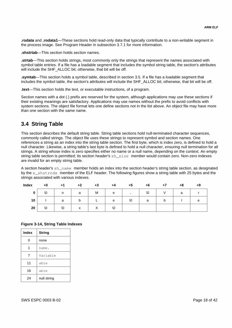
A section header's sh_name member holds an index into the section header’s string table section, as designatedby the e_shstrndx member of the ELF header. The following figures show a string table with 25 bytes and thestrings associated with various indexes.
Index +0 +1 +2 +3 +4 +5 +6 +7 +8 +9
0 \0 n a M e . \0 V a r
10 I a b L e \0 a b l e
20 \0 \0 x X \0
Figure 3-14, String Table Indexes
Index String
0 none
1 name.
7 Variable
11 able
16 able
24 null string
ARM ELF
SWS ESPC 0003 B-02 Page 19 of 42
As the example shows, a string table index may refer to any byte in the section. A string may appear more thanonce; references to sub-strings may exist; and a single string may be referenced multiple times. Unreferencedstrings also are allowed.
3.5 Symbol Table
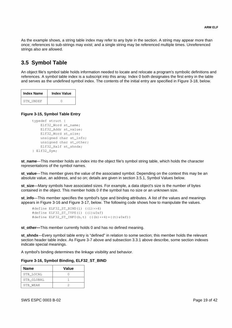
An object file's symbol table holds information needed to locate and relocate a program's symbolic definitions andreferences. A symbol table index is a subscript into this array. Index 0 both designates the first entry in the tableand serves as the undefined symbol index. The contents of the initial entry are specified in Figure 3-18, below.
Index Name Index Value
STN_UNDEF 0
Figure 3-15, Symbol Table Entry
typedef struct { Elf32_Word st_name; Elf32_Addr st_value; Elf32_Word st_size; unsigned char st_info; unsigned char st_other; Elf32_Half st_shndx;} Elf32_Sym;
st_name—This member holds an index into the object file's symbol string table, which holds the characterrepresentations of the symbol names.
st_value—This member gives the value of the associated symbol. Depending on the context this may be anabsolute value, an address, and so on; details are given in section 3.5.1, Symbol Values below.
st_size—Many symbols have associated sizes. For example, a data object's size is the number of bytescontained in the object. This member holds 0 if the symbol has no size or an unknown size.
st_info—This member specifies the symbol's type and binding attributes. A list of the values and meaningsappears in Figure 3-16 and Figure 3-17, below. The following code shows how to manipulate the values.
#define ELF32_ST_BIND(i) ((i)>>4)#define ELF32_ST_TYPE(i) ((i)&0xf)#define ELF32_ST_INFO(b,t) (((b)<<4)+((t)&0xf))
st_other—This member currently holds 0 and has no defined meaning.
st_shndx—Every symbol table entry is “defined” in relation to some section; this member holds the relevantsection header table index. As Figure 3-7 above and subsection 3.3.1 above describe, some section indexesindicate special meanings.
A symbol's binding determines the linkage visibility and behavior.
Figure 3-16, Symbol Binding, ELF32_ST_BIND
Name ValueSTB_LOCAL 0
STB_GLOBAL 1
STB_WEAK 2

ARM ELF
SWS ESPC 0003 B-02 Page 20 of 42
Symbol Binding, ELF32_ST_BIND (continued)
STB_LOPROC 13
STB_HIPROC 15
STB_LOCAL—Local symbols are not visible outside the object file containing their definition. Local symbols of thesame name may exist in multiple files without interfering with each other.
STB_GLOBAL—Global symbols are visible to all object files being combined. One file's definition of a globalsymbol will satisfy another file's undefined reference to the same global symbol.
STB_WEAK—Weak symbols resemble global symbols, but their definitions have lower precedence. Undefinedweak symbols (weak references) may have processor- or OS-specific semantics (see, for example, section 4.4.3,Weak symbols).
STB_LOPROC through STB_HIPROC—Values in this inclusive range are reserved for processor-specificsemantics.
In each symbol table, all symbols with STB_LOCAL binding precede the weak and global symbols. A symbol'stype provides a general classification for the associated entity.
Figure 3-17, Symbol Types, ELF32_ST_TYPE
Name Value Meaning
STT_NOTYPE 0 The symbol's type is not specified.
STT_OBJECT 1 The symbol is associated with a data object, such as a variable, an array, and so on.
STT_FUNC 2 The symbol is associated with a function or other executable code.
STT_SECTION 3 The symbol is associated with a section. Symbol table entries of this type existprimarily for relocation and normally have STB_LOCAL binding.
STT_FILE 4 A file symbol has STB_LOCAL binding, its section index is SHN_A BS, and itprecedes the other STB_LOCAL symbols for the file, if it is present.
STT_LOPROC 13
STT_HIPROC 15
Values in this inclusive range are reserved for processor-specific semantics. If asymbol's value refers to a specific location within a section, its section indexmember, st_shndx, holds an index into the section header table. As the sectionmoves during relocation, the symbol's value changes as well, and references to thesymbol continue to point to the same location in the program. Some special sectionindex values give other semantics.
The symbols in ELF object files convey specific information to the linker and loader. See section 4, ARM- andThumb-Specific Definitions, for a description of the actual linking model used in the system.
SHN_ABS—The symbol has an absolute value that will not change because of relocation.
SHN_COMMON—The symbol labels a common block that has not yet been allocated. The symbol's value givesalignment constraints, similar to a section's sh_addralign member. That is, the link editor will allocate the storagefor the symbol at an address that is a multiple of st_value. The symbol's size tells how many bytes are required.
SHN_UNDEF—This section table index means the symbol is undefined. When the link editor combines this objectfile with another that defines the indicated symbol, this file's references to the symbol will be linked to the actualdefinition.
As mentioned above, the symbol table entry for index 0 (STN_UNDEF) is reserved. It is shown in Figure 3-18.

ARM ELF
SWS ESPC 0003 B-02 Page 21 of 42
Figure 3-18, Symbol Table Entry: Index 0
Name Value Note
st_name 0 No name
st_value 0 Zero value
st_size 0 No size
st_info 0 No type, local binding
st_other 0
st_shndx SHN_UNDEF No section
3.5.1 Symbol Values
Symbol table entries for different object file types have slightly different interpretations for the st_valuemember.
� In relocatable files, st_value holds alignment constraints for a symbol whose section index isSHN_COMMON.
� In relocatable files, st_value holds a section offset for a defined symbol. That is, st_value is an offsetfrom the beginning of the section that st_shndx identifies.
� In executable and shared object files, st_value holds a virtual address1. To make these files' symbols moreuseful to the dynamic linker, the section offset (file interpretation) gives way to a virtual address (memoryinterpretation) for which the section number is irrelevant.
Although the symbol table values have similar meanings for different object files, the data allow efficient access bythe appropriate programs.
3.6 Relocation
Relocation is the process of connecting symbolic references with symbolic definitions. For example, when aprogram calls a function, the associated call instruction must transfer control to the proper destination address atexecution. In other words, relocatable files must have information that describes how to modify their sectioncontents, thus allowing executable and shared object files to hold the right information for a process's programimage. Relocation entries are these data.
Figure 3-19 Relocation Entries
typedef struct { typedef struct { Elf32_Addr r_offset; Elf32_Addr r_offset; Elf32_Word r_info; Elf32_Word r_info;} Elf32_Rel; Elf32_Sword r_addend;
} Elf32_Rela;
r_offset—This member gives the location at which to apply the relocation action. For a relocatable file, the valueis the byte offset from the beginning of the section to the storage unit affected by the relocation. For an executablefile or a shared object, the value is the virtual address of the storage unit affected by the relocation.
r_info—This member gives both the symbol table index with respect to which the relocation must be made, andthe type of relocation to apply. For example, a call instruction's relocation entry would hold the symbol table index
1 This virtual address is assigned during static linking. It can differ from the final execution address.

ARM ELF
SWS ESPC 0003 B-02 Page 22 of 42
of the function being called. If the index is STN_UNDEF, the undefined symbol index, the relocation uses 0 as thesymbol value. Relocation types are processor-specific; descriptions of their behavior appear in section 4.5,Relocation types. When the text in section 4.5 refers to a relocation entry's relocation type or symbol table index, itmeans the result of applying ELF32_R_TYPE or ELF32_R_SYM, respectively, to the entry's r_info member.
#define ELF32_R_SYM(i) ((i)>>8)#define ELF32_R_TYPE(i) ((unsigned char)(i))#define ELF32_R_INFO(s,t) (((s)<<8)+(unsigned char)(t))
r_addend—This member specifies a constant addend used to compute the value to be stored into the re-locatable field.
As shown in Figure 3-19 above, only Elf32_Rela entries contain an explicit addend. Entries of type Elf32_Rel storean implicit addend in the location to be modified. Depending on the processor architecture, one form or the othermight be necessary or more convenient. Consequently, an implementation for a particular machine may use oneform exclusively or either form depending on context.
A relocation section references two other sections: a symbol table and a section to modify. The section header'ssh_info and sh_link members, described in section 3.3, Sections, above, specify these relationships. Relocationentries for different object files have slightly different interpretations for the r_offset member.
� In re-locatable files, r_offset holds a section offset. That is, the relocation section itself describes how tomodify another section in the file; relocation offsets designate a storage unit within the second section.
� In executable and shared object files, r_offset holds a virtual address1. To make these files' relocation entriesmore useful for the dynamic linker, the section offset (file interpretation) gives way to a virtual address(memory interpretation).
Although the interpretation of r_offset changes for different object files to allow efficient access by the relevantprograms, the relocation types' meanings stay the same.
3.7 Program view
The following subsections describe the object file information and system actions that create running programs.Executable and shared object files statically represent programs. To execute such programs, the system uses thefiles to create dynamic program representations, or process images. A process image has segments that hold itstext, data, stack, and so on. This section describes the program header and complements preceding subsectionsof section 3, by describing object file structures that relate directly to program execution. The primary datastructure, a program header table, locates segment images within the file and contains other informationnecessary to create the memory image for the program.
Given an object file, the system must load it into memory for the program to run. After the system loads theprogram, it must complete the process image by resolving symbolic references among the object files thatcompose the process.
3.7.1 Program Header
An executable or shared object file's program header table is an array of structures, each describing a segment orother information the system needs to prepare the program for execution (see Figure 3-20 below). An object filesegment contains one or more sections. Program headers are meaningful only for executable and shared objectfiles. A file specifies its own program header size with the ELF header's e_phentsize and e_phnum members[see ELF Header in subsection 3.2].
1 This virtual address is assigned during static linking. It can differ from the final execution address.

ARM ELF
SWS ESPC 0003 B-02 Page 23 of 42
Figure 3-20, Program Header
typedef struct { Elf32_Word p_type; Elf32_Off p_offset; Elf32_Addr p_vaddr; Elf32_Addr p_paddr; Elf32_Word p_filesz; Elf32_Word p_memsz; Elf32_Word p_flags; Elf32_Word p_align;} Elf32_Phdr;
p_type—This member tells what kind of segment this array element describes or how to interpret the arrayelement's information. Type values and their meanings are given in Figure 3-21, below.
p_offset—This member gives the offset from the start of the file at which the first byte of the segment resides.
p_vaddr—This member gives the virtual address at which the first byte of the segment resides in memory.
p_paddr—On systems for which physical addressing is relevant, this member is reserved for the segment'sphysical address. This member requires operating system specific information.
p_filesz—This member gives the number of bytes in the file image of the segment; it may be zero.
p_memsz—This member gives the number of bytes in the memory image of the segment; it may be zero.
p_flags—This member gives flags relevant to the segment. Defined flag values are given in Figure 3-22, below.
p_align—Loadable process segments must have congruent values for p_vaddr and p_offset, modulo the pagesize. This member gives the value to which the segments are aligned in memory and in the file. Values 0 and 1mean that no alignment is required. Otherwise, p_align should be a positive, integral power of 2, and p_vaddrshould equal p_offset, modulo p_align.
Some entries describe process segments; others give supplementary information and do not contribute to theprocess image.
Figure 3-21, Segment Types, p_type
Name Value Meaning
PT_NULL 0 The array element is unused; other members' values are undefined. This typelets the program header table have ignored entries.
PT_LOAD 1 The array element specifies a loadable segment, described by p_filesz andp_memsz (for additional explanation, see PT_LOAD below).
PT_DYNAMIC 2 The array element specifies dynamic linking information. See subsection 4.7.
PT_INTERP 3 The array element specifies the location and size of a null-terminated pathname to invoke as an interpreter.
PT_NOTE 4 The array element specifies the location and size of auxiliary information.
PT_SHLIB 5 This segment type is reserved but has unspecified semantics.
PT_PHDR 6 The array element, if present, specifies the location and size of the programheader table itself (for additional explanation, see PT_ PHDR below).

ARM ELF
SWS ESPC 0003 B-02 Page 24 of 42
Segment Types, p_type (continued)
PT_LOPROC 0x70000000
PT_HIPROC 0x7fffffff
Values in this inclusive range are reserved for processor-specific semantics.
PT_LOAD—The bytes from the file are mapped to the beginning of the memory segment. If the segment'smemory size (p_memsz) is larger than the file size (p_filesz), the extra bytes are defined to hold the value 0 and tofollow the segment's initialized area. The file size may not be larger than the memory size. Loadable segmententries in the program header table appear in ascending order, sorted on the p_vaddr member.
PT_PHDR—The array element, if present, specifies the location and size of the program header table itself, bothin the file and in the memory image of the program. This segment type may not occur more than once in a file.Moreover, it may occur only if the program header table is part of the memory image of the program. If it ispresent, it must precede any loadable segment entry.
Note Unless specifically required elsewhere, all program header segment types are optional. That is, a file'sprogram header table may contain only those elements relevant to its contents.
Figure 3-22, Defined program header flags
Name Value Purpose
PF_X 1 The segment may be executed.
PF_W 2 The segment may be written to.
PF_R 4 The segment may be read.
PF_MASKPROC 0xf0000000 Reserved for processor-specific purposes (see 4.6, Program headers).
3.7.2 Note Section
Sometimes a vendor or system builder needs to mark an object file with special information that other programswill check for conformance, compatibility, etc. Sections of type SHT_NOTE and program header elements of typePT_NOTE can be used for this purpose. The note information in sections and program header elements holds anynumber of entries, each of which is an array of 4-byte words in the format of the target processor. Labels appearbelow to help explain note information organization, but they are not part of the specification.
Figure 3-23, Note Information
namesz
descsz
type
Name...
Desc...
namesz and name—The first namesz bytes in name contain a null-terminated character representation of theentry's owner or originator. There is no formal mechanism for avoiding name conflicts. By convention, vendors usetheir own name, such as "XYZ Computer Company,'' as the identifier. If no name is present, namesz contains 0.Padding is present, if necessary, to ensure 4-byte alignment for the descriptor. Padding is not included in namesz.

ARM ELF
SWS ESPC 0003 B-02 Page 25 of 42
descsz and desc—The first descsz bytes in desc hold the note descriptor. ELF places no constraints on adescriptor's contents. If no descriptor is present, descsz contains 0. Padding is present, if necessary, to ensure 4-byte alignment for the next note entry. Such padding is not included in descsz.
type—This word gives the interpretation of the descriptor. Each originator controls its own types; multipleinterpretations of a single type value may exist. Thus, a program must recognize both the name and the type tounderstand a descriptor. Types currently must be non-negative. ELF does not define what descriptors mean.
To illustrate, the note segment shown in Figure 3-24, below, holds two entries.
Note The system reserves note information with no name (namesz==0) and with a zero-length name(name[0]=='\0') but currently defines no types. All other names must have at least one non-nullcharacter.
Note Note information is optional. The presence of note information does not affect a program's TIS ELFconformance, provided the information does not affect the program's execution behavior. Otherwise, theprogram does not conform to the TIS ELF specification and has undefined behavior.
Figure 3-24, Example Note Segment
+0 +1 +2 +3
namesz 7
descsz 0
type 1 No descriptor
name X Y Z
C o \0 pad
namesz 7
descsz 8
type 3
name X Y Z
C o \0 pad
desc word 0
word 1
3.7.3 Program Loading
Program loading is the process by which the operating system creates or augments a process image. The mannerin which this process is accomplished and how the page management functions for the process are handled aredictated by the operating system and processor. See section 4.6, Program headers, for more details.
3.7.4 Dynamic Linking
The dynamic linking process resolves references either at process initialization time and/or at execution time.Some basic mechanisms need to be set up for a particular linkage model to work, and there are ELF sections andheader elements reserved for this purpose. The actual definition of the linkage model is determined by theoperating system and implementation. Therefore, the contents of these sections are both operating system andprocessor specific. (See section 4.7, Dynamic linking and relocation.)

ARM ELF
SWS ESPC 0003 B-02 Page 26 of 42
3.8 Special Sections Names
Various sections hold program and control information. Sections in the list below are specified in section 3 andsection 4 of this specification.
Figure 3-25, Special sections names
.bss .dynstr .interp .rodata
.comment .dynsym .line .rodata1
.data .fini .note .shstrtab
.data1 .got .plt .strtab
.debug .hash .rel name .symtab
.dynamic .init .rela name .text
Figure 3-26, Dynamic Section Names
_DYNAMIC
Figure 3-27, Dynamic Array Tags, d_tag
DT_NULL DT_NEEDED DT_PLTRELSZ DT_PLTGOT
DT_HASH DT_STRTAB DT_SYMTAB DT_RELA
DT_RELASZ DT_RELAENT DT_STRSZ DT_SYMENT
DT_INIT DT_FINI DT_SONAME DT_RPATH
DT_SYMBOLIC DT_REL DT_RELSZ DT_RELENT
DT_PLTREL DT_DEBUG DT_TEXTREL DT_JMPREL
DT_BIND_NOW DT_LOPROC DT_HIPROC
3.9 Pre-existing Extensions
There are naming conventions for ELF constants that have processor ranges specified. Names such as DT_,PT_, for processor specific extensions, incorporate the name of the processor: DT_M32_SPECIAL, for example.However, pre-existing processor extensions not using this convention will be supported.
Figure 3-28, Pre-existing Extensions
DT_JMP_REL
Section names reserved for a processor architecture are formed by placing an abbreviation of the architecturename ahead of the section name. The name should be taken from the architecture names used for e_machine.For instance .FOO.psect is the psect section defined by the FOO architecture. Existing extensions are called bytheir historical names.
Figure 3-29, Pre-existing Extensions
. .conflict .sdata .tdesc
.sbss .lit4 .lit8 .reginfo
.gptab .liblist

ARM ELF
SWS ESPC 0003 B-02 Page 27 of 42
4 ARM- AND THUMB-SPECIFIC DEFINITIONS
4.1 ELF header
The following tables summarize the ELF header field values specific to the ARM EABI.
Figure 4-1, ARM-specific machine and ident fields
Field Value and meaning
e_ident[EI_CLASS] ELFCLASS32—ARM and Thumb processors use 32-bit ELF.
e_ident[EI_DATA] ELFDATA2LSB when the execution environment is little-endian.ELFDATA2MSB when the execution environment is big-endian.(see the note immediately below).
e_machine EM_ARM (decimal 40).
Note The byte order of all data in an ARM ELF file is the byte order of data in the target executionenvironment, even if that data will only be consumed in the host (static linker) execution environment.The target byte order may differ from the host byte order.
Figure 4-2, ARM-specific e_flags
Field Value Meaning
EF_ARM_HASENTRY(0x02)
e_entry contains a program-loader entry point (see section4.1.1, Entry points, below).
EF_ARM_SYMSARESORTED(0x04)
Each subsection of the symbol table is sorted by symbol value(see section 4.4.8, Symbol table order, below)
EF_ARM_DYNSYMSUSESEGIDX(0x8)
Symbols in dynamic symbol tables that are defined in sectionsincluded in program segment n have st_shndx = n + 1. (seesection 4.4.9, Dynamic symbol table entries, below).
EF_ARM_MAPSYMSFIRST(0x10)
Mapping symbols precede other local symbols in the symboltable (see section 4.4.8, Symbol table order, below).
e_flags
EF_ARM_EABIMASK(0xFF000000)
(current version is 0x02000000)
This masks an 8-bit version number, the version of the ARMEABI to which this ELF file conforms. This EABI is version 2. Avalue of 0 denotes unknown conformance.
Figure 4-3, Interpretation of the entry point
Field Value and meaning
e_entry
(see section 4.1.1,Entry points, below).
In an executable ELF file, e_entry is the virtual address of the image’s unique entrypoint, or 0 if the image does not have a unique entry point.
In a re-locatable ELF file, e_entry is the offset of the entry point in the section flaggedby SHF_ENTRYSECT or 0 if there is no entry point.

ARM ELF
SWS ESPC 0003 B-02 Page 28 of 42
4.1.1 Entry points
Entry point means a location to which control may be transferred by the execution environment.
A program can have many entry points—for example, corresponding to reset, interrupt, software interrupt,undefined instruction exception, and so on. A program loader cannot start such a program. A shared objectusually has no entry point. Again, a loader cannot start execution.
An ELF executable that can be started by a program loader must have an entry address. It can be 0.EF_ARM_HASENTRY distinguishes an entry address of 0 from no program loader entry address. Consumersshould accept a non-zero entry address, or a zero entry address with EF_ARM_HASENTRY set in e_flags.Producers should set EF_ARM_HASENTRY if the executable has an entry point.
In a re-locatable ELF file:
� The section containing an entry point is flagged by SHF_ENTRYSECT (see section 4.3, Section headers).
� The ELF header field e_entry gives the offset of the entry point in that section.
� There can be at most one entry point in a re-locatable ELF file.
In an ARM executable ELF file, several program segments can be mapped at the same virtual address so:
� The program segment containing the entry address is flagged by PF_ARM_ENTRY (see section4.6, Programheaders).
4.2 Section names
An ARM section name is one that begins with one of the standard prefixes listed below that have pre-definedmeanings, or a name containing a dollar ($) character. No other section names have special significance underthe ARM EABI.
Note Bracketed SHF_ALLOC flags are set only if the section is contained in an executable program segment(one of type PT_LOAD or PT_DYNAMIC—see section 4.6, Program headers).
Note There can be many sections with the same name in an ELF file.
Figure 4-4, ARM standard section names and their meanings
Name prefix Section type Section attributes Explanation
.bss SHT_NOBITS SHF_ALLOC+SHF_WRITE Uninitialized data—set to zero before execution.
.comment SHT_PROGBITS None A comment from the producing tool—versiondata.
.data SHT_PROGBITS SHF_ALLOC+SHF_WRITE Initialized data.
.debug… SHT_PROGBITS None Debugging tables (may include line numberdata).
.dynamic SHT_DYNAMIC SHF_ALLOC[+SHF_WRITE]
Dynamic linking information—may not bewritable.
.dynsym SHT_DYNSYM [SHF_ALLOC] A symbol table for dynamic linking.
.hash SHT_HASH [SHF_ALLOC] A symbol hash table.
.line SHT_PROGBITS None Line number data for debugging.
.rodata SHT_PROGBITS SHF_ALLOC Initialized read-only data.

ARM ELF
SWS ESPC 0003 B-02 Page 29 of 42
ARM standard section names and their meanings (continued)
.relname
.relanameSHT_RELSHT_RELA
[SHF_ALLOC] Relocation data. By convention, the continuationof the name is the name of the section beingrelocated.
.shstrtab SHT_STRTAB None The section name string table.
.strtab SHT_STRTAB [SHF_ALLOC] A string table for a symbol table.
.symtab SHT_SYMTAB [SHF_ALLOC] A symbol table for static linking.
.text SHT_PROGBITS SHF_ALLOC+SHF_EXECINSTR
Program instructions and inline literal data.
4.3 Section headers
Figure 4-5, ARM-EABI-specific values for sh_flags
Name Value Purpose
SHF_ENTRYSECT 0x10000000 The section contains an entry point (see section 4.1.1, Entry points).
SHF_COMDEF 0x80000000 The section may be multiply defined in the input to a link step (seesection 4.3.1, Common sections).
4.3.1 Common sections
The SHF_COMDEF attribute denotes that there may be multiple definitions of this section. From each set ofidentically named sections having the SHF_COMDEF attribute, the linker retains only one representative (but itretains all identically named sections not having the SHF_COMDEF attribute).
Object producers must ensure that it does not matter which variant of a common section is retained. In general,this requires:
� All variants of a common section must define the same global symbols.
� If the section contains code, all variants must have the same functional interface. However, different variantsmay have a different size, a different content, or be differently relocated.
� If the section contains data, all variants must have the same size, the same content, and be similarlyrelocated.
This specification does not define which variant of a common section a linker should retain.
4.3.2 Section alignment
The ARM EABI requires that each executable section must be aligned on a 4-byte boundary. Any section havingthe SHF_ALLOC attribute must have sh_addralign ≥ 4. Other sections can be aligned as required. For example,debugging tables usually have no alignment requirements, and data sections input to a static linker can benaturally aligned.

ARM ELF
SWS ESPC 0003 B-02 Page 30 of 42
4.3.3 Link and info fields
Figure 4-6, Interpretation of sh_link and sh_info
sh_type sh_link sh_info
SHT_SYMTAB,SHT_DYNSYM
The section header index ofthe associated string table.
One more than the symbol table index of the last localsymbol (the last one with binding STB_LOCAL).
4.4 Symbols
4.4.1 Symbol value
See also section 3.5.1, Symbol Values.
In a re-locatable file:
� For a COMMON symbol defined in the SHN_COMMON section, st_value gives its alignment constraint (theallocated address of the symbol must be zero modulo st_value).
� For a symbol definition, st_value gives its offset within the section identified by st_shndx.
In executable and shared object files:
� For symbols defined in sections included in executable program segments, st_value is a target-system virtualaddress assigned when the ELF file is statically linked.
� Otherwise, st_value is a virtual address in an address space specific to the operating environment (forexample, symbols defined in debugging tables).
4.4.2 Symbol size
For a symbol definition of type STT_FUNC, st_size gives the length of the function in bytes, or 0 if this is unknown.
For a symbol definition of type STT_OBJECT, st_size gives the length in bytes of the associated data object or 0 ifthis is unknown.
4.4.3 Weak symbols
No library is searched to satisfy an undefined weak symbol (st_shndx = SHN_UNDEF, ELF32_ST_BIND =STB_WEAK), or weak reference. It is not an error for a weak reference to remain unsatisfied.
The value of an undefined weak symbol is:
� P + 4 if location P is subject to branch relocation (R_ARM_PC24, .R_ARM_THM_PC22, R_ARM_XPC25,R_ARM_THM_XPC22).
� P if location P is subject to a PC-relative or SB-relative relocation.
� Otherwise, 0.
You can think of these values as branch offset 0 (branch to the next instruction), offset 0, and absolute 0,respectively. That is, the value of an undefined weak symbol is always the sort of 0 appropriate to the relocationdirective referring to it.
A weak symbol definition may coexist with a non-weak definition, but all references to the symbol resolve to thenon-weak definition.

ARM ELF
SWS ESPC 0003 B-02 Page 31 of 42
A file may make both a weak reference and a non-weak reference through distinct symbols that have the samename (this can help a linker perform unused section elimination).
4.4.4 Symbol names
A symbol that names a C or assembly language entity should have the name of that entity. For example, a Cfunction called calculate generates a symbol called calculate (not _calculate).
C++ and Java follow their own language-specific rules.
All symbol names containing a dollar character (‘$’) are reserved to the ARM EABI.
Symbol names are case sensitive and are matched exactly by linkers.
4.4.5 Sub-class and super-class symbols
A symbol $Sub$$name is the sub-class version of name. A symbol $Super$$name is the super-class version ofname. In the presence of a definition of both name and $Sub$$name:
� A reference to name resolves to the definition of $Sub$$name.
� A reference to $Super$$name resolves to the definition of name.
It is an error to refer to $Sub$$name, or to define $Super$$name, or to use $Sub$$… or $Super$$… recursively.
4.4.6 Function address constants and pointers to code
The address of an ARM function is a multiple of 4. So is the st_value field of a symbol labeling an ARM-state codeaddress.
The address of a Thumb function is a multiple of 2. So is the st_value field of a symbol labeling a Thumb-statecode address.
Nonetheless, wherever a Thumb function address is crystallized in memory, the least significant bit of the addressshould be set. This allows a call from either instruction-set state to execute the pointed-to function in Thumb-state.
In practice, a linker must set the Thumb-state bit (bit 0 of the address) whenever it relocates a data value withrespect to a Thumb-state code symbol.
4.4.7 Mapping and tagging symbols
A section of an ARM ELF file can contain a mixture of ARM code, Thumb code, and data.
There are inline transitions between code and data at literal pool boundaries. There can also be inline transitionsbetween ARM code and Thumb code, for example in ARM-Thumb inter-working veneers.
Linkers, machine-level debuggers, profiling tools, and disassembly tools need to map images accurately. Forexample, setting an ARM breakpoint on a Thumb location, or in a literal pool, can crash the program beingdebugged, ruining the debugging session.
ARM ELF entities are mapped (see section 4.4.7.1 below) and tagged (see section 4.4.7.2 below) using localsymbols (with binding STB_LOCAL).
To assist consumers, mapping and tagging symbols should be collated first in the symbol table, before othersymbols with binding STB_LOCAL.
To allow properly collated mapping and tagging symbols to be skipped by consumers that have no interest inthem, the first such symbol should have the name $m and its st_value field equal to the total number of mappingand tagging symbols (including the $m) in the symbol table.

ARM ELF
SWS ESPC 0003 B-02 Page 32 of 42
4.4.7.1 Mapping symbols
$a labels the first byte of a sequence of ARM instructions. Its type is STT_FUNC.
$d labels the first byte of a sequence of data items. Its type is STT_OBJECT.
$t labels the first byte of a sequence of Thumb instructions. Its type is STT_FUNC.
This list of mapping symbols may be extended in the future.
Section-relative mapping symbols
Mapping symbols defined in a section define a sequence of half-open address intervals that cover the addressrange of the section. Each interval starts at the address defined by a mapping symbol, and continues up to, butnot including, the address defined by the next (in address order) mapping symbol or the end of the section. Acorollary is that there must be a mapping symbol defined at the beginning of each section.
Consumers can ignore the size of a section-relative mapping symbol. Producers can set it to 0.
Absolute mapping symbols
Because of the need to crystallize a Thumb address with the Thumb-bit set, absolute symbol of type STT_FUNC(symbols of type STT_FUNC defined in section SHN_ABS) need to be mapped with $a or $t.
The extent of a mapping symbol defined in SHN_ABS is [st_value, st_value + st_size), or [st_value, st_value + 1)if st_size = 0, where [x, y) denotes the half-open address range from x, inclusive, to y, exclusive.
In the absence of a mapping symbol, a consumer can interpret a function symbol with an odd value as the Thumbcode address obtained by clearing the least significant bit of the value. This interpretation is deprecated, and itmay not work in the future.
4.4.7.2 Tagging symbols
Tagging symbols help consumers by tagging specific entities in a program. In each case, a consumer can ignorethe size of a tagging symbol. A producer should set the size to the size of the tagged entity or 0.
$b labels a Thumb BL instruction. Its type is STT_FUNC, its size is 4 bytes.
$f labels a function pointer constant (static pointer to code). Its type is STT_OBJECT, its size is 4 bytes.
$p labels the final, PC-modifying instruction of an indirect function call. Its type is STT_FUNC.(An indirect call is a call through a function pointer variable). $p does not label the PC-modifyinginstruction of a function return sequence. Its size is 2 bytes in Thumb-state, 4 bytes in ARM-state.
$m gives (in its st_value field) the total number of mapping and tagging symbols in the symbol table.
This list of tagging symbols is not exhaustive and others may be defined in the future.
4.4.8 Symbol table order
The order of symbols in the symbol table should be:
� Local symbols
- $m
- Other mapping and tagging symbols sorted in virtual address order
- Other local symbols sorted in virtual address order (save that each symbol of type STT_FILE shouldprecede all the symbols of type STT_SECTION that are associated with it).
� Global symbols.

ARM ELF
SWS ESPC 0003 B-02 Page 33 of 42
If the EF_ARM_MAPSYMSFIRST flag is set in the e_flags field of the ELF header (see section 4.1, ELF header):
� A consumer can rely on mapping and tagging symbols preceding other local symbols.
The first local symbol will have the name $m and its st_value field will be equal to the total number of mappingand tagging symbols (including the $m) in the symbol table.
Otherwise, a consumer must assume that mapping symbols are interleaved with other local symbols.
If EF_ARM_SYMSARESORTED is set in the e_flags field of the ELF header (see section 4.1, ELF header):
� Each subsection of the symbol table is sorted by increasing st_value ( symbols of type STT_FILE excepted).
� Each symbol of type STT_FILE precedes all the symbols of type STT_SECTION associated with it (thus aconsuming debugger can easily map each image section to the source file it was created from).
Otherwise, a consumer should not assume that symbol table subsections are sorted by address.
4.4.9 Dynamic symbol table entries
In a linkable object file, a symbol is defined in a section of type SHT_SYMTAB. In an executable or shared objectfile, a dynamic symbol table is defined in the dynamic program segment (see section 4.7.1 The dynamic segment,below). A section view of an executable or shared object file is optional. When the section-relative interpretation ofa symbol’s value gives way to the virtual address interpretation, it is useful to know in which program segment asymbol is defined if, for example, this is not uniquely determined by the symbol’s virtual address.
Under the ARM EABI, a symbol in a dynamic symbol table (a .dynsym section) that is defined in a sectionincluded in program segment n has st_shndx = n + 1.
EF_ARM_DYNSYMSUSESEGIDX is set in the e_flags field of the ELF header (see section 4.1, ELF header) totell consumers that st_shndx identifies the program segment in which the symbol is defined.
4.5 Relocation types
ELF defines two sorts of relocation directive, SHT_REL, and SHT_RELA. Both identify:
� A section containing the storage unit—byte, half-word, word, or instruction—being relocated.
� An offset within the section—or the address within an executable program—of the storage unit itself.
� A symbol, the value of which helps to define a new value for the storage unit.
� A relocation type that defines the computation to be performed. Computations are performed using 2’scomplement, 32-bit, unsigned arithmetic with silent overflow.
� An addend, that also helps to define a new value for the storage unit.
The addend may be encoded wholly in a field of the storage unit being relocated—relocation sort SHT_REL—orpartly there and partly in the addend field of the relocation directive—relocation sort SHT_RELA.
Tables below describe the computation associated with each relocation type, using the following notation:
A denotes the addend used to compute the new value of the storage unit being relocated.
- It is the value extracted from the storage unit being relocated (relocation directives of sort SHT_REL) orthe sum of that value and the r_addend field of the relocation directive (sort SHT_RELA).
- If it has a unit, the unit is bytes. An encoded address or offset value is converted to bytes on extractionfrom a storage unit and re-encoded on insertion into a storage unit.
P denotes the place (section offset or address of the storage unit) being re-located. It is the sum of ther_offset field of the relocation directive and the base address of the section being re-located.

ARM ELF
SWS ESPC 0003 B-02 Page 34 of 42
S denotes the value of the symbol whose symbol table index is given in the r_info field of the relocationdirective.
B denotes the base address of the consolidated section in which the symbol is defined. For relocations oftype R_ARM_SBREL32, this is the least static data address (the static base).
Figure 4-7, ARM relocation types 0-16
Type Name Field Computation and meaning
0 R_ARM_NONE Any No relocation.Encodes dependencies between sections.
1 R_ARM_PC24 ARM B/BL S – P + A
2 R_ARM_ABS32 32-bit word S + A
3 R_ARM_REL32 32-bit word S – P + A
4 R_ARM_PC13 ARM LDR r, [pc,…] S – P + A
5 R_ARM_ABS16 16-bit half-word S + A
6 R_ARM_ABS12 ARM LDR/STR S + A
7 R_ARM_THM_ABS5 Thumb LDR/STR S + A
8 R_ARM_ABS8 8-bit byte S + A
9 R_ARM_SBREL32 32-bit word S – B + A
10 R_ARM_THM_PC22 Thumb BL pair S – P+ A
11 R_ARM_THM_PC8 Thumb LDR r, [pc,…] S – P + A
12 R_ARM_AMP_VCALL9 AMP VCALL Obsolete—SA-1500 only.
13 R_ARM_SWI24 ARM SWI S + A
14 R_ARM_THM_SWI8 Thumb SWI S + A
15 R_ARM_XPC25 ARM BLX S – P+ A
16 R_ARM_THM_XPC22 Thumb BLX pair S – P+ A
Note A relocation directive of type R_ARM_NONE records that the section containing the place to be relocateddepends on the section defining the symbol mentioned in the relocation directive in a way otherwiseinvisible to a static linker. It therefore prevents the removal of sections that might appear to be unused.
Figure 4-8, ARM relocation types 17-31, reserved to ARM Linux
Type Name Field Computation and meaning
17-19 Reserved to ARM LINUX
20 R_ARM_COPY 32 bit word Copy symbol at dynamic link time.
21 R_ARM_GLOB_DAT 32 bit word Create GOT entry.
22 R_ARM_JUMP_SLOT 32 bit word Create PLT entry.
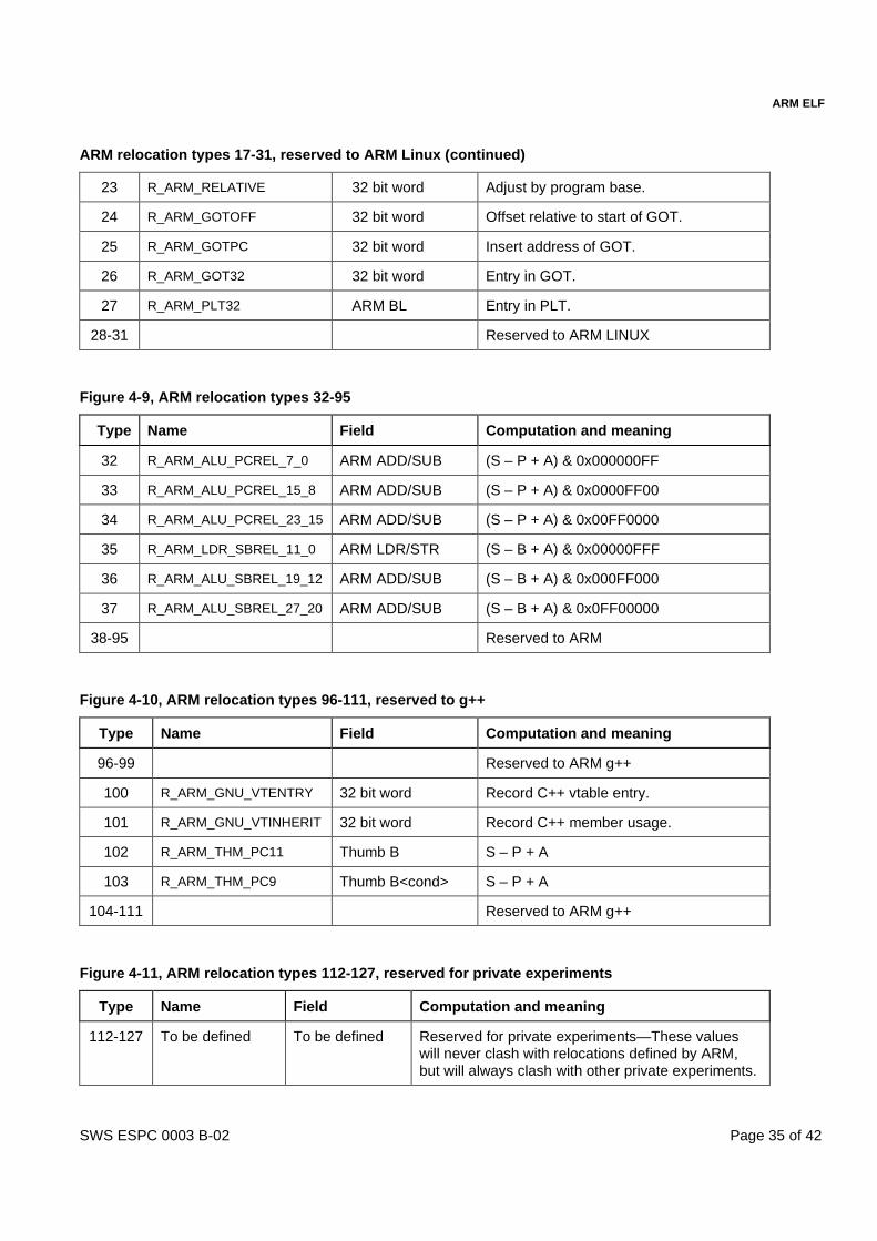
ARM ELF
SWS ESPC 0003 B-02 Page 35 of 42
ARM relocation types 17-31, reserved to ARM Linux (continued)
23 R_ARM_RELATIVE 32 bit word Adjust by program base.
24 R_ARM_GOTOFF 32 bit word Offset relative to start of GOT.
25 R_ARM_GOTPC 32 bit word Insert address of GOT.
26 R_ARM_GOT32 32 bit word Entry in GOT.
27 R_ARM_PLT32 ARM BL Entry in PLT.
28-31 Reserved to ARM LINUX
Figure 4-9, ARM relocation types 32-95
Type Name Field Computation and meaning
32 R_ARM_ALU_PCREL_7_0 ARM ADD/SUB (S – P + A) & 0x000000FF
33 R_ARM_ALU_PCREL_15_8 ARM ADD/SUB (S – P + A) & 0x0000FF00
34 R_ARM_ALU_PCREL_23_15 ARM ADD/SUB (S – P + A) & 0x00FF0000
35 R_ARM_LDR_SBREL_11_0 ARM LDR/STR (S – B + A) & 0x00000FFF
36 R_ARM_ALU_SBREL_19_12 ARM ADD/SUB (S – B + A) & 0x000FF000
37 R_ARM_ALU_SBREL_27_20 ARM ADD/SUB (S – B + A) & 0x0FF00000
38-95 Reserved to ARM
Figure 4-10, ARM relocation types 96-111, reserved to g++
Type Name Field Computation and meaning
96-99 Reserved to ARM g++
100 R_ARM_GNU_VTENTRY 32 bit word Record C++ vtable entry.
101 R_ARM_GNU_VTINHERIT 32 bit word Record C++ member usage.
102 R_ARM_THM_PC11 Thumb B S – P + A
103 R_ARM_THM_PC9 Thumb B<cond> S – P + A
104-111 Reserved to ARM g++
Figure 4-11, ARM relocation types 112-127, reserved for private experiments
Type Name Field Computation and meaning
112-127 To be defined To be defined Reserved for private experiments—These valueswill never clash with relocations defined by ARM,but will always clash with other private experiments.
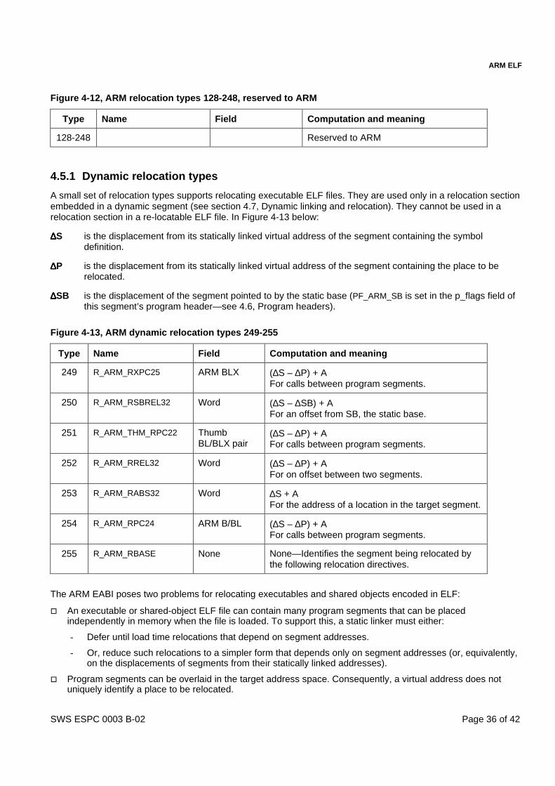
ARM ELF
SWS ESPC 0003 B-02 Page 36 of 42
Figure 4-12, ARM relocation types 128-248, reserved to ARM
Type Name Field Computation and meaning
128-248 Reserved to ARM
4.5.1 Dynamic relocation types
A small set of relocation types supports relocating executable ELF files. They are used only in a relocation sectionembedded in a dynamic segment (see section 4.7, Dynamic linking and relocation). They cannot be used in arelocation section in a re-locatable ELF file. In Figure 4-13 below:
∆∆∆∆S is the displacement from its statically linked virtual address of the segment containing the symboldefinition.
∆∆∆∆P is the displacement from its statically linked virtual address of the segment containing the place to berelocated.
∆∆∆∆SB is the displacement of the segment pointed to by the static base (PF_ARM_SB is set in the p_flags field ofthis segment’s program header—see 4.6, Program headers).
Figure 4-13, ARM dynamic relocation types 249-255
Type Name Field Computation and meaning
249 R_ARM_RXPC25 ARM BLX (∆S – ∆P) + AFor calls between program segments.
250 R_ARM_RSBREL32 Word (∆S – ∆SB) + AFor an offset from SB, the static base.
251 R_ARM_THM_RPC22 ThumbBL/BLX pair
(∆S – ∆P) + AFor calls between program segments.
252 R_ARM_RREL32 Word (∆S – ∆P) + AFor on offset between two segments.
253 R_ARM_RABS32 Word ∆S + AFor the address of a location in the target segment.
254 R_ARM_RPC24 ARM B/BL (∆S – ∆P) + AFor calls between program segments.
255 R_ARM_RBASE None None—Identifies the segment being relocated bythe following relocation directives.
The ARM EABI poses two problems for relocating executables and shared objects encoded in ELF:
� An executable or shared-object ELF file can contain many program segments that can be placedindependently in memory when the file is loaded. To support this, a static linker must either:
- Defer until load time relocations that depend on segment addresses.
- Or, reduce such relocations to a simpler form that depends only on segment addresses (or, equivalently,on the displacements of segments from their statically linked addresses).
� Program segments can be overlaid in the target address space. Consequently, a virtual address does notuniquely identify a place to be relocated.

ARM ELF
SWS ESPC 0003 B-02 Page 37 of 42
The R_ARM_RBASE type informs a consumer that following relocation directives relocate places in the segment(the source segment) identified by its ELF32_R_SYM field:
� If ELF32_R_SYM = n > 0, following relocations apply to source segment (n-1).
� If ELF32_R_SYM = n = 0, following relocations identify the source segment by virtual address only.
Consumers can ignore the r_offset field. Producers should set it to zero.
Prior to the first R_ARM_RBASE directive, relocation directives identify the source segment by virtual address.
Displacement-based dynamic relocation types
The ARM EABI defines displacement-based dynamic relocation types. Their advantage is that if an ELF filecontains only dynamic relocations and each program segment is loaded at its statically linked address, there is norelocation work to do at load time.
For the remaining dynamic relocation types:
� The r_offset field gives the virtual address of the place being relocated. Its offset in the source segment is thedifference between r_offset and the statically linked address of the source segment.
� ELF32_R_SYM – 1 indexes the program segment (the target segment) with respect to which the place isbeing re-located.
R_ARM_RABS32 directs a consumer to add to the place the displacement of the target segment from its staticallylinked virtual address.
R_ARM_RPC24, R_ARM_RXPC25, R_ARM_RREL32, and R_ARM_THM_RPC22 direct a consumer to add tothe place the difference between the displacement of the target segment (from its statically linked virtual address)and the displacement of the source segment (from its statically linked virtual address).
R_ARM_RSBREL32 is similar to R_ARM_RREL32, except that the segment addressed by the static base registeris used as the source segment (the PF_ARM_SB flag is set in the p_flags field of this program segment’s header.See section 4.6, Program headers).
PC-relative re-location is defined using the difference of two displacements to support the displacement of aprogram by more than the maximum BL offset.
Re-location may fail at load time if program segments are moved apart too much—beyond the address range of aBL instruction, for example.
4.5.2 Multiple relocation
A field can be relocated many times, but this cannot be exploited to generate a compound relocation because anintermediate step may overflow, even when the compound relocation would not (consider, for example, adding0x1000004 to, then subtracting 0x1000000 from, a 16-bit field).
4.5.3 Field extraction and insertion
The byte order of a field in an ELF file is its byte order in the target execution environment. This may differ fromthe byte order in the host (linker) execution environment.
ARM instructions are 4-byte aligned (relocation types 1, 4, 6, 12, 13, 15, 32-37). Thumb instructions are 2-bytealigned (relocation types 7, 10, 11, 14, 16, 102-103).
Other fields have no alignment requirement. For example, a 4-byte field (relocation types 2, 3, and 9) may occur atany address.
An ARM ELF consumer never needs to interpret an instruction word to determine how to relocate it. The sub-fieldsto relocate and the unit of relocation (byte, half word, word, or double word) are evident from the relocation type.

ARM ELF
SWS ESPC 0003 B-02 Page 38 of 42
Labeling the least significant bit of a 32-bit ARM instruction word, or 16-bit Thumb instruction word, bit 0,instruction fields to be relocated are given in Figure 4-14 and Figure 4-15, below.
Figure 4-14, Re-locatable ARM instruction fields
R_ARM_PC24 Bits 0-23 encode a signed offset, in units of 4-byte instructions (thus 24 bitsencode a branch offset of +- 2^25 bytes).
R_ARM_PC13 Bits 0-11 encode an unsigned byte offset. Bit 23 encodes the direction of theoffset—0 means to a lower address than P, 1 to a higher address.
R_ARM_ABS12 Bits 0-11 encode an unsigned byte offset.
R_ARM_SWI24 Bits 0-23 encode the ARM SWI number.
R_ARM_XPC25 Bits 0-23 encode a signed offset in units of 4-byte words. Bit 24 encodes bit 1 ofthe target Thumb address.
R_ARM_ALU_PCREL_7_0,R_ARM_ALU_PCREL_15_8,R_ARM_ALU_PCREL_23_15
Bits 0-7 contain the bit value of the selected field. Bits 8-11 contain 0, 0xc, or 0x8,half the rotate-right needed to shift the value to its field position. Bits 23 and 22encode the sign of the value—01 means negative, 10 means positive.
R_ARM_LDR_SBREL_11_0 Bits 0-11 contain the bit value of the selected field. Bit 23 encodes the sign of thevalue—0 means negative, 1 means positive.
R_ARM_ALU_SBREL_19_12,R_ARM_ALU_SBREL_27_20
Bits 0-7 contain the bit value of the selected field. Bits 8-11 contain 0xa or 0x6,half the rotate-right needed to shift the value to its field position. Bits 23 and 22encode the sign of the value—01 means negative, 10 means positive.
Figure 4-15, Re-locatable Thumb instruction fields
R_ARM_THM_ABS5 Bits 6-10 encode a 5-bit unsigned offset in units of 4-byte words (Thumb LDRB/LDRHcannot be relocated).
R_ARM_THM_PC22 Bits 0-10 encode the 11 most significant bits of the branch offset. Bits 0-10 of the nextinstruction word encode the 11 least significant bits. The unit is 2-byte instructions.
R_ARM_THM_PC8 Bits 0-7 encode an 8-bit unsigned offset in units of 4-byte words. An initial offset of 255must be interpreted as an offset of –1 (so the initial offset range is [-1, 254]).
R_ARM_THM_SWI8 Bits 0-7 encodes the Thumb SWI number.
R_ARM_THM_XPC22 Bits 0-10 encode the 11 most significant bits of the branch offset. Bits 1-10 of the nextinstruction word encode the bits 1-10 of the branch offset. Bit 0 must be set to 0. The unitis 2-byte instructions.
Note When a Thumb LDR [pc, …] instruction is subject to a REL-sort relocation of type R_ARM_THM_PC8,there must be a way to encode the offset to the place containing the instruction in the initial value of theinstruction. Using the value 255 to encode –1 does this.
4.5.4 Relocations that depend on the type of the target location
As explained in section 4.4.6, Function address constants and pointers to code, the address of a Thumb functionmust have bit 0 set to 1. Bit 0 must be set whenever the location to which the relocated place points (the targetlocation) is mapped (see section 4.4.7, Mapping and tagging symbols) as Thumb code.
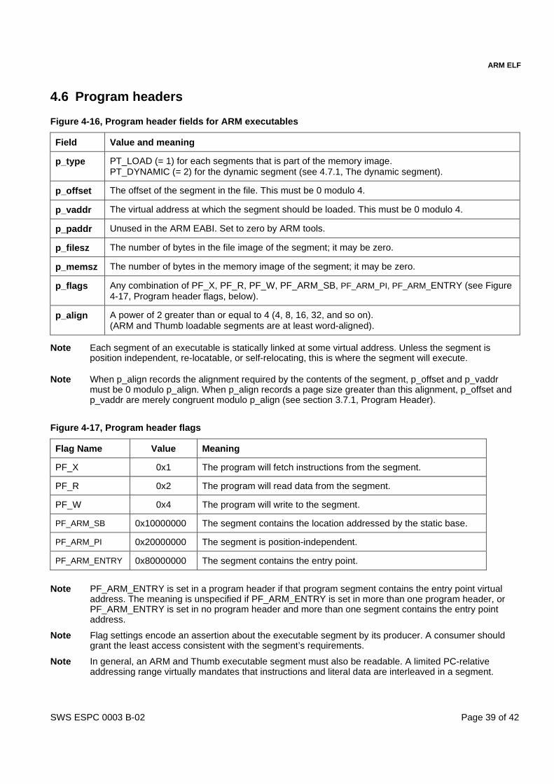
ARM ELF
SWS ESPC 0003 B-02 Page 39 of 42
4.6 Program headers
Figure 4-16, Program header fields for ARM executables
Field Value and meaning
p_type PT_LOAD (= 1) for each segments that is part of the memory image.PT_DYNAMIC (= 2) for the dynamic segment (see 4.7.1, The dynamic segment).
p_offset The offset of the segment in the file. This must be 0 modulo 4.
p_vaddr The virtual address at which the segment should be loaded. This must be 0 modulo 4.
p_paddr Unused in the ARM EABI. Set to zero by ARM tools.
p_filesz The number of bytes in the file image of the segment; it may be zero.
p_memsz The number of bytes in the memory image of the segment; it may be zero.
p_flags Any combination of PF_X, PF_R, PF_W, PF_ARM_SB, PF_ARM_PI, PF_ARM_ENTRY (see Figure4-17, Program header flags, below).
p_align A power of 2 greater than or equal to 4 (4, 8, 16, 32, and so on).(ARM and Thumb loadable segments are at least word-aligned).
Note Each segment of an executable is statically linked at some virtual address. Unless the segment isposition independent, re-locatable, or self-relocating, this is where the segment will execute.
Note When p_align records the alignment required by the contents of the segment, p_offset and p_vaddrmust be 0 modulo p_align. When p_align records a page size greater than this alignment, p_offset andp_vaddr are merely congruent modulo p_align (see section 3.7.1, Program Header).
Figure 4-17, Program header flags
Flag Name Value Meaning
PF_X 0x1 The program will fetch instructions from the segment.
PF_R 0x2 The program will read data from the segment.
PF_W 0x4 The program will write to the segment.
PF_ARM_SB 0x10000000 The segment contains the location addressed by the static base.
PF_ARM_PI 0x20000000 The segment is position-independent.
PF_ARM_ENTRY 0x80000000 The segment contains the entry point.
Note PF_ARM_ENTRY is set in a program header if that program segment contains the entry point virtualaddress. The meaning is unspecified if PF_ARM_ENTRY is set in more than one program header, orPF_ARM_ENTRY is set in no program header and more than one segment contains the entry pointaddress.
Note Flag settings encode an assertion about the executable segment by its producer. A consumer shouldgrant the least access consistent with the segment’s requirements.
Note In general, an ARM and Thumb executable segment must also be readable. A limited PC-relativeaddressing range virtually mandates that instructions and literal data are interleaved in a segment.

ARM ELF
SWS ESPC 0003 B-02 Page 40 of 42
4.7 Dynamic linking and relocation
A dynamically linked executable or shared object undergoes its final stage of linking when it is:
� Loaded into memory by a program loader.
� Prepared for ROM by a ROM builder.
An executable or shared object to be linked dynamically may:
� List one or more shared objects (shared libraries) with which it should be linked.
� Refer to symbols defined by these shared objects, the execution environment, or the ROM builder. Thesereferences appear as undefined symbols in the dynamic symbol table.
� Define symbols that can be referred to by these shared objects, the execution environment, or the ROMbuilder. These symbols are defined in the dynamic symbol table.
� List locations to be relocated whose values depend on:
- The actual execution addresses given to program segments.
- The values of symbols defined during dynamic linking.
In general, some storage units will need to be relocated when symbolic references are resolved.
4.7.1 The dynamic segment
If an ARM executable or shared object needs dynamic linking, or is re-locatable, it contains a program segment oftype PT_DYNAMIC. The dynamic segment contains:
� A dynamic section (see 4.7.3, The dynamic section) that describes the dynamic segment.
� A string table used by the symbol table and directly by some dynamic section entries (see 3.4, String Table).
� A dynamic symbol table section. This has the same format as a symbol table (see 3.5, Symbol Table), butmay use a different interpretation of st_shndx (see 4.4.9, Dynamic symbol table entries).
� A section containing relocations (a section of sort SHT_REL and/or SHT_RELA). This has the same format asany other relocation section (see 3.6, Relocation).
� A hash table that accelerates use of the symbol table (see 4.7.4, The hash table section).
Optionally, section headers of the following types may describe these sub-sections of the dynamic segment:
� SHT_DYNAMIC—the dynamic array itself.
� SHT_STRTAB—the string table.
� SHT_DYNSYM—the symbol table.
� SHT_REL and/or SHT_RELA—the relocation section(s).
� SHT_HASH—the symbol hash table.
Dynamic linkers do not use this section view.
4.7.2 The dynamic segment program header
The dynamic segment program header has p_type = PT_DYNAMIC (= 2).
The ARM EABI defines no meaning for the following fields of the program header of a dynamic segment:
� p_vaddr, p_paddr, p_memsz, p_align.
� The PF_MASKPROC sub-field of p_flags.
Operating environments are free to define their own semantics for these fields.
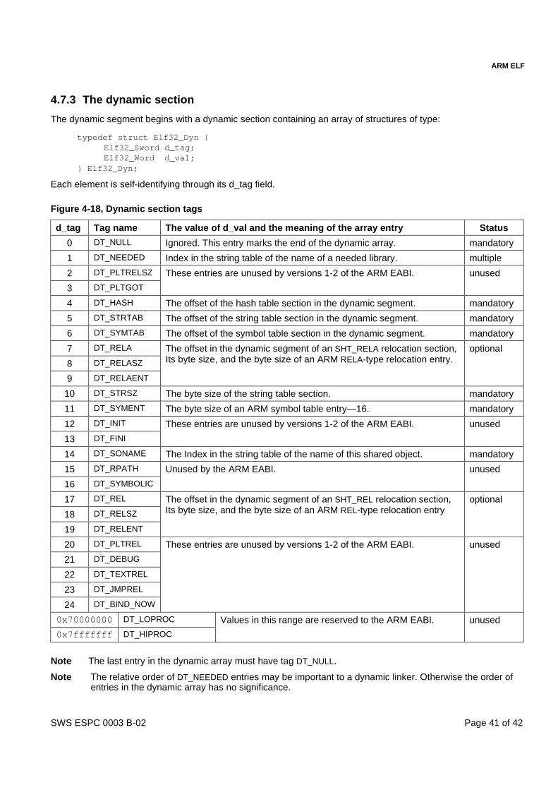
ARM ELF
SWS ESPC 0003 B-02 Page 41 of 42
4.7.3 The dynamic section
The dynamic segment begins with a dynamic section containing an array of structures of type:
typedef struct Elf32_Dyn {Elf32_Sword d_tag;Elf32_Word d_val;
} Elf32_Dyn;
Each element is self-identifying through its d_tag field.
Figure 4-18, Dynamic section tags
d_tag Tag name The value of d_val and the meaning of the array entry Status
0 DT_NULL Ignored. This entry marks the end of the dynamic array. mandatory
1 DT_NEEDED Index in the string table of the name of a needed library. multiple
2 DT_PLTRELSZ
3 DT_PLTGOT
These entries are unused by versions 1-2 of the ARM EABI. unused
4 DT_HASH The offset of the hash table section in the dynamic segment. mandatory
5 DT_STRTAB The offset of the string table section in the dynamic segment. mandatory
6 DT_SYMTAB The offset of the symbol table section in the dynamic segment. mandatory
7 DT_RELA
8 DT_RELASZ
9 DT_RELAENT
The offset in the dynamic segment of an SHT_RELA relocation section,Its byte size, and the byte size of an ARM RELA-type relocation entry.
optional
10 DT_STRSZ The byte size of the string table section. mandatory
11 DT_SYMENT The byte size of an ARM symbol table entry—16. mandatory
12 DT_INIT
13 DT_FINI
These entries are unused by versions 1-2 of the ARM EABI. unused
14 DT_SONAME The Index in the string table of the name of this shared object. mandatory
15 DT_RPATH
16 DT_SYMBOLIC
Unused by the ARM EABI. unused
17 DT_REL
18 DT_RELSZ
19 DT_RELENT
The offset in the dynamic segment of an SHT_REL relocation section,Its byte size, and the byte size of an ARM REL-type relocation entry
optional
20 DT_PLTREL
21 DT_DEBUG
22 DT_TEXTREL
23 DT_JMPREL
24 DT_BIND_NOW
These entries are unused by versions 1-2 of the ARM EABI. unused
0x70000000 DT_LOPROC
0x7fffffff DT_HIPROC
Values in this range are reserved to the ARM EABI. unused
Note The last entry in the dynamic array must have tag DT_NULL.
Note The relative order of DT_NEEDED entries may be important to a dynamic linker. Otherwise the order ofentries in the dynamic array has no significance.

ARM ELF
SWS ESPC 0003 B-02 Page 42 of 42
Note A DT_SONAME entry is mandatory only for shared objects, not for dynamically linked executables.
Following the dynamic array, the dynamic segment includes:
� A hash table section (see 4.7.4, The hash table section).
� A symbol table section (called .dynsym in the section view—see 3.5, Symbol Table).
� A string table section (see 3.4, String Table).
� Relocation sections (see 3.6, Relocation).
The order of these sections is unimportant. The offset of each in the dynamic segment is given by thecorresponding entry in the dynamic array.
4.7.4 The hash table section
The hash table section is described by the following pseudo-C structure:
struct Elf32_HashTable { Elf32_Word nBuckets;
Elf32_Word nChains;Elf32_Word bucket[nBuckets];Elf32_Word chain[nChains];
};
Both bucket and chain hold symbol table indexes. Indexes start at 0. Bucket can have any convenient size. Thereis one chain entry for each symbol in the symbol table (nChains = number of symbols).
Bucket and chain implement a chained overflow hash table access structure for the symbol table. If h is the resultof applying the ELF hash function (see Figure 4-19, The ELF hash function) to a symbol’s name, the start of thechain of symbols that hash to this bucket is given by:
bucket[h % nBuckets]
For each symbol index s, chain[s] gives the index of the next symbol that hashes to the same bucket. Zeroindexes the dummy symbol and is used as the end of chain pointer.
Figure 4-19, The ELF hash function
unsigned long elf_hash(const unsigned char *name) { unsigned long h, g;
for (h = 0; *name != 0; ++name){
h = (h << 4) + *name;g = h & 0xf0000000;if (g != 0) h ^= g >> 24;h &= ~g;
}return h;
}


