Swivel Sector Radial Penstock - cmovalves.com · - DIN 19704 Hydraulic Steel Structures. Criteria...
9
RADIAL PENSTOCK CT SERIES C.M.O. Amategui Aldea 142, 20400 Txarama-Tolosa (SPAIN) TEC-CT.ES00 Tel. National: 902.40.80.50 Fax: 902.40.80.51 / Tel. International: 34.943.67.33.99 Fax: 34.943.67.24.40 [email protected] http://www.cmo.es page 1 24/03/2015 - “TAINTOR” type radial penstock. - Mechanically welded stopboard with sectoral shape, fitted with side wheels to guarantee correct guiding of the penstock throughout its run. - The stopboard is fitted with arms for swivelling and to radially transmit the hydraulic thrust to the concrete through the embedded turning points. - Square or rectangular section penstock valve. - Various construction materials available. - Option of 3- or 4-side watertight integrity. General applications: There are two main types of design within the radial penstocks: • 3-side seal: Designed for installation in dam channels or spillways. They are used for water level control; with this design the fluid can overflow above the stopboard. • 4-side seal: Designed for installation in water connection points or bottom outlets. These are used as a regulation element. They are suitable for the following applications: - Dams - Irrigation - Hydroelectric power stations - Ducts Sizes: The construction sizes for this type of penstocks are adapted to the needs of each particular project. Working (ΔP): As is the case with the dimensions of the penstock, the working ΔP is also adapted in accordance with the specific needs of each project. Civil engineering work: Given the large dimensions of the CT radial penstocks and the high hydraulic forces they have to withstand, the most common assembly system (recommended by CMO) is with the turn points embedded in concrete. This type of assembly requires a series of gaps in the civil engineering work for the installation of the penstock. Design regulations and directives: - DIN 19704 Hydraulic Steel Structures. Criteria for Design and Calculation. - DIN 19705 Hydraulic Steel Structures. Recommendation for Design, Construction and Erection. - Machinery Directive: DIR 2006/42/EC (MACHINERY) Quality dossier: - Material and testing certificates can be supplied on request. Swivel Sector Radial Penstock fig. 1
Transcript of Swivel Sector Radial Penstock - cmovalves.com · - DIN 19704 Hydraulic Steel Structures. Criteria...

R A D I A L P E N S T O C K C T S E R I E S
C.M.O. Amategui Aldea 142, 20400 Txarama-Tolosa (SPAIN) TEC-CT.ES00
Tel. National: 902.40.80.50 Fax: 902.40.80.51 / Tel. International: 34.943.67.33.99 Fax: 34.943.67.24.40 [email protected] http://www.cmo.es page 1
24/03/2015
- “TAINTOR” type radial penstock. - Mechanically welded stopboard with sectoral shape, fitted with side wheels to guarantee correct
guiding of the penstock throughout its run. - The stopboard is fitted with arms for swivelling and to radially transmit the hydraulic thrust to the
concrete through the embedded turning points. - Square or rectangular section penstock valve. - Various construction materials available. - Option of 3- or 4-side watertight integrity.
General applications: There are two main types of design within the radial penstocks: • 3-side seal: Designed for installation in dam
channels or spillways. They are used for water level control; with this design the fluid can overflow above the stopboard.
• 4-side seal: Designed for installation in water connection points or bottom outlets. These are used as a regulation element.
They are suitable for the following applications: - Dams - Irrigation - Hydroelectric power stations - Ducts
Sizes: The construction sizes for this type of penstocks are adapted to the needs of each particular project.
Working (ΔP): As is the case with the dimensions of the penstock, the working ΔP is also adapted in accordance with the specific needs of each project.
Civil engineering work: Given the large dimensions of the CT radial penstocks and the high hydraulic forces they have to withstand, the most common assembly system (recommended by CMO) is with the turn points embedded in concrete. This type of assembly requires a series of gaps in the civil engineering work for the installation of the penstock.
Design regulations and directives: - DIN 19704 Hydraulic Steel Structures. Criteria for Design and Calculation. - DIN 19705 Hydraulic Steel Structures. Recommendation for Design, Construction and Erection. - Machinery Directive: DIR 2006/42/EC (MACHINERY)
Quality dossier: - Material and testing certificates can be supplied on request.
Swivel Sector Radial Penstock
fig. 1
R A D I A L P E N S T O C K C T S E R I E S
C.M.O. Amategui Aldea 142, 20400 Txarama-Tolosa (SPAIN) TEC-CT.ES00
Tel. National: 902.40.80.50 Fax: 902.40.80.51 / Tel. International: 34.943.67.33.99 Fax: 34.943.67.24.40 [email protected] http://www.cmo.es page 2
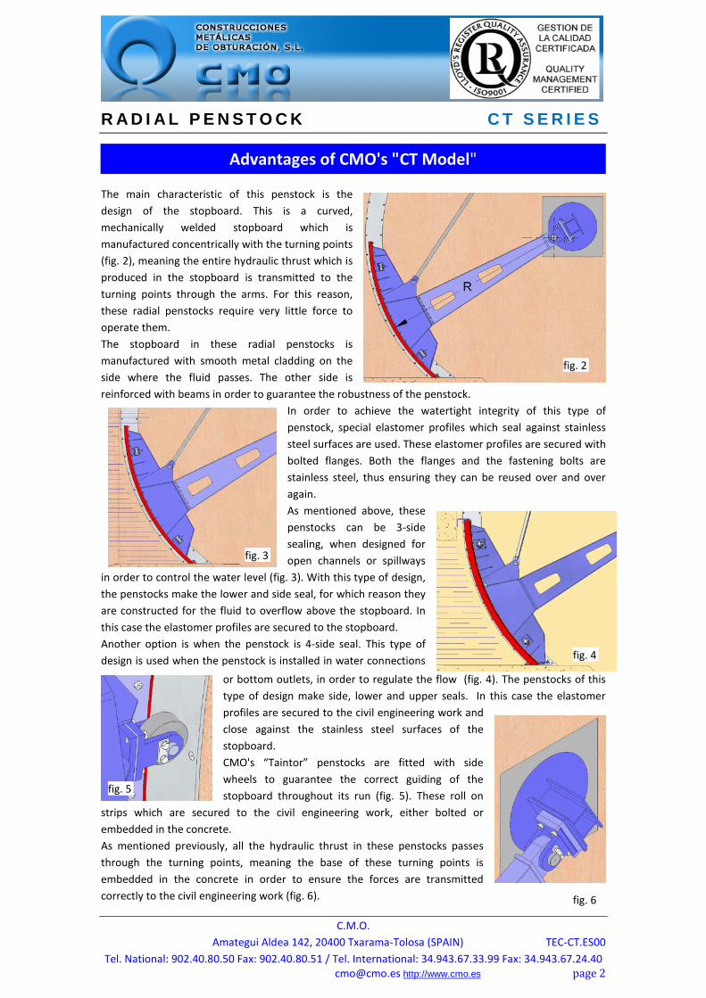
The main characteristic of this penstock is the design of the stopboard. This is a curved, mechanically welded stopboard which is manufactured concentrically with the turning points (fig. 2), meaning the entire hydraulic thrust which is produced in the stopboard is transmitted to the turning points through the arms. For this reason, these radial penstocks require very little force to operate them. The stopboard in these radial penstocks is manufactured with smooth metal cladding on the side where the fluid passes. The other side is reinforced with beams in order to guarantee the robustness of the penstock.
In order to achieve the watertight integrity of this type of penstock, special elastomer profiles which seal against stainless steel surfaces are used. These elastomer profiles are secured with bolted flanges. Both the flanges and the fastening bolts are stainless steel, thus ensuring they can be reused over and over again. As mentioned above, these penstocks can be 3-side sealing, when designed for open channels or spillways
in order to control the water level (fig. 3). With this type of design, the penstocks make the lower and side seal, for which reason they are constructed for the fluid to overflow above the stopboard. In this case the elastomer profiles are secured to the stopboard. Another option is when the penstock is 4-side seal. This type of design is used when the penstock is installed in water connections
or bottom outlets, in order to regulate the flow (fig. 4). The penstocks of this type of design make side, lower and upper seals. In this case the elastomer profiles are secured to the civil engineering work and close against the stainless steel surfaces of the stopboard. CMO's “Taintor” penstocks are fitted with side wheels to guarantee the correct guiding of the stopboard throughout its run (fig. 5). These roll on
strips which are secured to the civil engineering work, either bolted or embedded in the concrete. As mentioned previously, all the hydraulic thrust in these penstocks passes through the turning points, meaning the base of these turning points is embedded in the concrete in order to ensure the forces are transmitted correctly to the civil engineering work (fig. 6).
Advantages of CMO's "CT Model"
fig. 2
fig. 3
fig. 4
fig. 6
fig. 5
R A D I A L P E N S T O C K C T S E R I E S
C.M.O. Amategui Aldea 142, 20400 Txarama-Tolosa (SPAIN) TEC-CT.ES00
Tel. National: 902.40.80.50 Fax: 902.40.80.51 / Tel. International: 34.943.67.33.99 Fax: 34.943.67.24.40 [email protected] http://www.cmo.es page 3
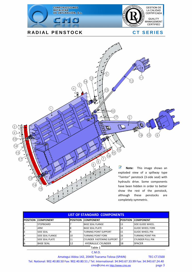
LIST OF STANDARD COMPONENTS POSITION COMPONENT POSITION COMPONENT POSITION COMPONENT 1 STOPBOARD 7 BASE SEAL FLANGE 13 SIDE GUIDE WHEEL 2 ARM 8 BASE SEAL PLATE 14 GUIDE WHEEL FORK 3 SIDE SEAL 9 TURNING POINT SUPPORT 15 GUIDE WHEEL PIN 4 SIDE SEAL FLANGE 10 TURNING POINT FORK 16 TURNING POINT PIN 5 SIDE SEAL PLATE 11 CYLINDER FASTENING SUPPORT 17 CYLINDER PULL PIN
6 BASE SEAL 12 HYDRAULIC CYLINDER 18 SPACER
Note: This image shows an exploded view of a spillway type "Taintor" penstock (3-side seal) with hydraulic drive. Some components have been hidden in order to better show the rest of the penstock, although these penstocks are completely symmetric.
Table 1

R A D I A L P E N S T O C K C T S E R I E S
C.M.O. Amategui Aldea 142, 20400 Txarama-Tolosa (SPAIN) TEC-CT.ES00
Tel. National: 902.40.80.50 Fax: 902.40.80.51 / Tel. International: 34.943.67.33.99 Fax: 34.943.67.24.40 [email protected] http://www.cmo.es page 4
1 - STOPBOARD
The stopboard of CT penstocks is mechanically welded and has a curved shape, meaning it is concentric with the penstock turn points (fig. 2). The stopboard is manufactured with smooth metal cladding on the side where the fluid passes (fig. 8), whilst the other side is reinforced with horizontal and vertical beams in order to guarantee its rigidity and resistance. Depending on the dimensions and loads the stopboard has to withstand, it can even be reinforced with a box beam (fig. 9); this last option considerably improves resistance to torsion. In order to choose the most suitable design of the different elements, structural calculations are carried out by finite elements and CAD modelling systems (fig. 10). These stopboards are guided throughout the run, to which end side wheels (fig. 5) which are adjusted to the assembly on site are used. These roll on strips which are secured to the civil engineering work. They can be embedded in the concrete whenever a housing has been envisaged for this purpose; otherwise they will be bolted on the walls of the civil engineering work. A series of arms are attached to the stopboard in order to transmit the hydraulic thrust generated throughout the civil engineering work. These arms are bolted to the stopboard, so they can be taken down and the penstock can be easily transported. The standard manufacturing materials are AISI304 stainless steel and S275JR carbon steel, although other materials such as AISI316 stainless steel, etc., are available on request. As standard, carbon steel penstocks are painted with an anti-corrosive protection of 250 microns of EPOXY (colour RAL 5015). Other types of anti-corrosive protections are available.
DESIGN CHARACTERISTICS
fig. 8
fig. 9
fig. 10
R A D I A L P E N S T O C K C T S E R I E S
C.M.O. Amategui Aldea 142, 20400 Txarama-Tolosa (SPAIN) TEC-CT.ES00
Tel. National: 902.40.80.50 Fax: 902.40.80.51 / Tel. International: 34.943.67.33.99 Fax: 34.943.67.24.40 [email protected] http://www.cmo.es page 5
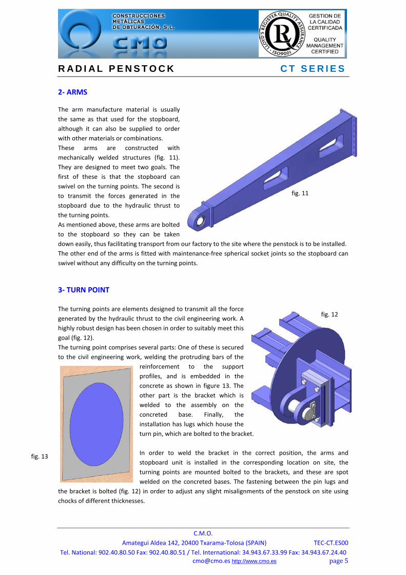
2- ARMS The arm manufacture material is usually the same as that used for the stopboard, although it can also be supplied to order with other materials or combinations. These arms are constructed with mechanically welded structures (fig. 11). They are designed to meet two goals. The first of these is that the stopboard can swivel on the turning points. The second is to transmit the forces generated in the stopboard due to the hydraulic thrust to the turning points. As mentioned above, these arms are bolted to the stopboard so they can be taken down easily, thus facilitating transport from our factory to the site where the penstock is to be installed. The other end of the arms is fitted with maintenance-free spherical socket joints so the stopboard can swivel without any difficulty on the turning points.
3- TURN POINT The turning points are elements designed to transmit all the force generated by the hydraulic thrust to the civil engineering work. A highly robust design has been chosen in order to suitably meet this goal (fig. 12). The turning point comprises several parts: One of these is secured to the civil engineering work, welding the protruding bars of the
reinforcement to the support profiles, and is embedded in the concrete as shown in figure 13. The other part is the bracket which is welded to the assembly on the concreted base. Finally, the installation has lugs which house the turn pin, which are bolted to the bracket. In order to weld the bracket in the correct position, the arms and stopboard unit is installed in the corresponding location on site, the turning points are mounted bolted to the brackets, and these are spot welded on the concreted bases. The fastening between the pin lugs and
the bracket is bolted (fig. 12) in order to adjust any slight misalignments of the penstock on site using chocks of different thicknesses.
fig. 11
fig. 12
fig. 13

R A D I A L P E N S T O C K C T S E R I E S
C.M.O. Amategui Aldea 142, 20400 Txarama-Tolosa (SPAIN) TEC-CT.ES00
Tel. National: 902.40.80.50 Fax: 902.40.80.51 / Tel. International: 34.943.67.33.99 Fax: 34.943.67.24.40 [email protected] http://www.cmo.es page 6
4- ELEMENTS FOR SEALING AND ROLLING STRIPS As mentioned, these penstocks are fitted with side wheels to guide the stopboard throughout its run. These wheels roll on metal strips which are secured to the walls of the civil
engineering work. The attachment can be carried out in two different ways: If housings are envisaged for the rolling strips when carrying out the civil engineering work, these will be embedded in the concrete to achieve complete passage and avoid any protrusions in the walls on site (fig. 14). If the civil engineering work is already complete and housings have not been envisaged for the rolling strips, they will be supported on the side walls (fig. 15), meaning the penstock will be reduced by around 10 millimetres on each side.
The watertight integrity of these penstocks is achieved through special elastomer profiles which close against a series of stainless steel surfaces. In channel or spillway penstocks (3-side seal), the watertight integrity seals are secured to the stopboard using stainless steel flanges, as shown in figures 14 and 15. These seals close against stainless steel surfaces; in these cases the option of widening the rolling strip has been chosen, thus ensuring the same strip carries out both functions. Whenever the penstock is a water connection or bottom outlet (4-side seal), the watertight integrity seals will be secured on the mouth which is embedded in the civil engineering work and will close against the stainless steel surfaces of the stopboard (fig. 16).
5- WATERTIGHT INTEGRITY The watertight integrity of these penstocks is achieved through special elastomer profiles which close against a series of stainless steel surfaces. As mentioned above, there are two types of penstocks, the difference between them being the number of seals and their attachment system.
- When the penstock is designed for a channel or spillway, it will have seals on the base and on the two sides, known as a 3-side seal. In this case the elastomer profiles are attached to the stopboard and close against the stainless steel strips which are secured in the civil engineering work. This type of penstock is designed to withstand a maximum water load equal to the height of the stopboard plus the water overflow mass specified by the customer.
fig. 14
fig. 15
fig. 14
fig. 16
R A D I A L P E N S T O C K C T S E R I E S
C.M.O. Amategui Aldea 142, 20400 Txarama-Tolosa (SPAIN) TEC-CT.ES00
Tel. National: 902.40.80.50 Fax: 902.40.80.51 / Tel. International: 34.943.67.33.99 Fax: 34.943.67.24.40 [email protected] http://www.cmo.es page 7
- When the penstock is designed to work as a water connection or bottom outlet, it will have seals in the base, in the two sides and in the lintel, known as a 4-side seal. In this case the elastomer profiles are secured to the mouth embedded in the civil engineering work and close against the stopboard's stainless steel surfaces. This type of penstock is designed to withstand the water load specified by the customer.
Whatever the type of penstock, these special elastomer seals are secured using flanges. Both these flanges and the bolts used to secure them are always stainless steel, meaning they can be used several times. Although the standard watertight seal is EPDM, there are other types of materials in order to choose the most suitable, in accordance with the working applications for the penstock (work temperature, fluid type, etc). The characteristics described below are the most common ones, and they are also summarised in table 2:
Watertight seal materials
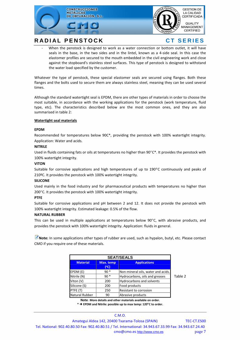
EPDM Recommended for temperatures below 90C*, providing the penstock with 100% watertight integrity. Application: Water and acids. NITRILE Used in fluids containing fats or oils at temperatures no higher than 90C*. It provides the penstock with 100% watertight integrity. VITON Suitable for corrosive applications and high temperatures of up to 190C continuously and peaks of 210ºC. It provides the penstock with 100% watertight integrity. SILICONE Used mainly in the food industry and for pharmaceutical products with temperatures no higher than 200C. It provides the penstock with 100% watertight integrity. PTFE Suitable for corrosive applications and pH between 2 and 12. It does not provide the penstock with 100% watertight integrity. Estimated leakage: 0.5% of the flow. NATURAL RUBBER This can be used in multiple applications at temperatures below 90C, with abrasive products, and provides the penstock with 100% watertight integrity. Application: fluids in general.
Note: In some applications other types of rubber are used, such as hypalon, butyl, etc. Please contact CMO if you require one of these materials.
Note: More details and other materials available on order. * EPDM and Nitrile: possible up to max temp: 120C to order.
SEAT/SEALS Material Max. temp
(ºC) Applications
EPDM (E) 90 * Non-mineral oils, water and acids. Nitrile (N) 90 * Hydrocarbons, oils and greases Viton (V) 200 Hydrocarbons and solvents Silicone (S) 200 Food products PTFE (T) 250 Resistant to corrosion Natural Rubber 90 Abrasive products
Table 2

R A D I A L P E N S T O C K C T S E R I E S
C.M.O. Amategui Aldea 142, 20400 Txarama-Tolosa (SPAIN) TEC-CT.ES00
Tel. National: 902.40.80.50 Fax: 902.40.80.51 / Tel. International: 34.943.67.33.99 Fax: 34.943.67.24.40 [email protected] http://www.cmo.es page 8
6- ACTUATORS The most common drive system for these penstocks is the oil-hydraulic system (fig. 17). This type of drive comprises double acting hydraulic cylinder(s) and an oil-hydraulic unit. Depending on the dimensions of the penstock and of the water load to be withstood, two cylinders (one on each side) or a single cylinder may be required. Whenever the penstock has two cylinders, the hydraulic cylinders will be connected so the same oil pressure is injected in both cylinders, meaning both cylinders apply the same force. These hydraulic cylinders are fitted with front and rear hinges, which include maintenance-free spherical socket joints. These socket joints guarantee optimal fastening of the cylinder both with the penstock and with the fastening mounts. The oil-hydraulic unit has two electrical motor pumps which work alternately in order to spread the work between them. If one of them does not work, for example in the event of a power failure, the unit also has a manual emergency pump which can be used to operate the penstock. Although the oil-hydraulic drive is currently the most used, other types of drive can be employed. For example, another system would be using a geared motor. There are several methods to transmit the movement generated by this type of drive to the penstock: by pinion and chain, cable and drum, pinion and rack, etc. In all of them, whenever there are several pulling points on the penstock, these are joined mechanically in order to ensure that the pulling forces on the penstock are balanced.
There are different accessories and options to adjust the penstock to the customer's needs in each project, such as: Indication rule: Positioning of an aluminium rule on one of the side walls of the civil engineering work in order to know the degree of opening of the penstock at any moment. Mechanical limit switches or inductive sensors (fig. 18): Installation of inductive detectors or limit switches for specific penstock position indication.
ACCESSORIES AND OPTIONS
fig. 17
fig. 18
R A D I A L P E N S T O C K C T S E R I E S
C.M.O. Amategui Aldea 142, 20400 Txarama-Tolosa (SPAIN) TEC-CT.ES00
Tel. National: 902.40.80.50 Fax: 902.40.80.51 / Tel. International: 34.943.67.33.99 Fax: 34.943.67.24.40 [email protected] http://www.cmo.es page 9
Positioners: When the position of the penstock is to be known remotely, a positioner is installed to indicate the position of the penstock continuously. Automatic interlocking: In the case of penstocks with hydraulic drive, this can be fitted with automatic interlocking for open position. This consists of a system which detects that the penstock has lost its position, sending a signal to the oil-hydraulic unit to start it up and for the penstock to recover the required position. Emergency manual actuator: This allows manual operation of the penstock in the event of power failure. The oil-hydraulic unit is fitted with a manual emergency pump in the case of hydraulic drive. In the case of geared motor drive, there is the option of coupling a manual emergency system to it. Epoxy coating: All carbon steel components of CMO penstocks are EPOXY coated, giving them great resistance to corrosion and an excellent surface finish. CMO’s standard colour is blue RAL-5015.