Switching frequency control method based on short ...
8
http://ijrc.sciedupress.com International Journal of Robotics and Control 2019, Vol. 2, No. 1 ORIGINAL ARTICLES Switching frequency control method based on short prediction horizon control algorithm of Quasi-Z source inverter Shengchao Li 1 , Sile Ma *2 , Xiaojing Ma 2 , Xiangyuan Jiang 2 , Shuai Li 3 1 College of Marine Scinec and Technology, Northwestern Polytechnical University, Xi’an, China 2 The Institute of Marine Science and Technolgoy (IMST), Department of Control Science and Engineering, Shandong University, Qingdao, China 3 Department of Computing, The Hong Kong Polytechnic University, Hung Hom, Kowloon, Hong Kong, China Received: October 23, 2018 Accepted: November 20, 2018 Online Published: December 7, 2018 DOI: 10.5430/ijrc.v2n1p1 URL: https://doi.org/10.5430/ijrc.v2n1p1 ABSTRACT In order to overcome the problem of large inductance current ripple and poor output current quality caused by lower switching frequency in model predictive control (MPC). A short prediction horizon control algorithm is proposed, and the relationship between the prediction horizon and the switching frequency is analyzed, which also considered the influence of the switching frequency of the inverter. In the proposed algorithm the optimal vector is selected based on the historical switching state. Finally the proposed method can effectively reduce the inductor current ripple and improve the output current quality of the inverter, which is proved by simulation and experiment. Key Words: MPC, Switching frequency, Prediction horizon 1. I NTRODUCTION Compared with the traditional inverter, the quasi-Z source in- verter [1] introduces a shoot-through boost mechanism, which has excellent performances such as high reliability, flexible buck-boost and high anti-interference. Because of those ad- vantages, the quasi-Z source inverter has been widely used in photovoltaic power generation, [2, 3] wind power and other distributed power generation systems. [4] The DC side of the quasi-Z source inverter uses a shoot-through mechanism to boost the DC input V in, and inverts the DC to AC to provide energy for the load. Therefore, the DC side and the AC side need to be controlled at the same time. The traditional PI control method have a good control effect on the system, but a separate controller needs to be designed, and in order to be able to control the multiple variables simultaneously, which requires multiple control loops, which will increase the complexity of the system design. MPC has been rapidly developed since the 1970s. [5, 6] Com- pared with PI and other control methods, MPC can control multiple variables at the same time, and which has the advan- tages of simple structure and good control effect, [7–9] espe- cially for the non-minimum phase systems such as MIMO systems and quasi-Z-source inverters. [10–12] The MPC uses the current feedback value to predict the next switching state, and the switching of the switching tube is determined by * Correspondence: Sile Ma; Email: [email protected]; Address: The Institute of Marine Science and Technolgoy (IMST), Department of Control Science and Engineering, Shandong University, Qingdao, China. Published by Sciedu Press 1
Transcript of Switching frequency control method based on short ...

http://ijrc.sciedupress.com International Journal of Robotics and Control 2019, Vol. 2, No. 1
ORIGINAL ARTICLES
Switching frequency control method based on shortprediction horizon control algorithm of Quasi-Z sourceinverter
Shengchao Li1, Sile Ma∗2, Xiaojing Ma2, Xiangyuan Jiang2, Shuai Li3
1College of Marine Scinec and Technology, Northwestern Polytechnical University, Xi’an, China2The Institute of Marine Science and Technolgoy (IMST), Department of Control Science and Engineering, Shandong University,Qingdao, China3Department of Computing, The Hong Kong Polytechnic University, Hung Hom, Kowloon, Hong Kong, China
Received: October 23, 2018 Accepted: November 20, 2018 Online Published: December 7, 2018DOI: 10.5430/ijrc.v2n1p1 URL: https://doi.org/10.5430/ijrc.v2n1p1
ABSTRACT
In order to overcome the problem of large inductance current ripple and poor output current quality caused by lower switchingfrequency in model predictive control (MPC). A short prediction horizon control algorithm is proposed, and the relationshipbetween the prediction horizon and the switching frequency is analyzed, which also considered the influence of the switchingfrequency of the inverter. In the proposed algorithm the optimal vector is selected based on the historical switching state. Finallythe proposed method can effectively reduce the inductor current ripple and improve the output current quality of the inverter,which is proved by simulation and experiment.
Key Words: MPC, Switching frequency, Prediction horizon
1. INTRODUCTION
Compared with the traditional inverter, the quasi-Z source in-verter[1] introduces a shoot-through boost mechanism, whichhas excellent performances such as high reliability, flexiblebuck-boost and high anti-interference. Because of those ad-vantages, the quasi-Z source inverter has been widely usedin photovoltaic power generation,[2, 3] wind power and otherdistributed power generation systems.[4] The DC side of thequasi-Z source inverter uses a shoot-through mechanism toboost the DC input Vin, and inverts the DC to AC to provideenergy for the load. Therefore, the DC side and the AC sideneed to be controlled at the same time. The traditional PIcontrol method have a good control effect on the system,
but a separate controller needs to be designed, and in orderto be able to control the multiple variables simultaneously,which requires multiple control loops, which will increasethe complexity of the system design.
MPC has been rapidly developed since the 1970s.[5, 6] Com-pared with PI and other control methods, MPC can controlmultiple variables at the same time, and which has the advan-tages of simple structure and good control effect,[7–9] espe-cially for the non-minimum phase systems such as MIMOsystems and quasi-Z-source inverters.[10–12] The MPC usesthe current feedback value to predict the next switching state,and the switching of the switching tube is determined by
∗Correspondence: Sile Ma; Email: [email protected]; Address: The Institute of Marine Science and Technolgoy (IMST), Department of ControlScience and Engineering, Shandong University, Qingdao, China.
Published by Sciedu Press 1
http://ijrc.sciedupress.com International Journal of Robotics and Control 2019, Vol. 2, No. 1
the predicted value. Therefore, MPC belongs to variablefrequency control. Mostafa Mosa et al.[13, 14] used the MPCalgorithm to regulate the inductor current, capacitor voltageand load current of the quasi-Z-source inverter, althoughwhich achieved a good tracking effect, the prediction horizonis a little longer, which may cause the inductor current rippleto be relatively large, and the inverter’s output characteristicsare relatively poor. Abualkasim Bakeer et al.[15] analyzedthe state equations of the inductor current, then divided theinductor current into two states, that is the shoot-throughstate and the non-shoot-through state, which reduced thecalculation of the MPC. The real-time performance of MPCis greatly improved, but the inverter still has a low switch-ing frequency phenomenon. Ayman Ayad et al.[16] addedtwo capacitors and two inductors into the predictive model,which improved the accuracy of the predictive model, andthe average switching frequency is added to the cost functionto reduce the switching loss. However, the impact on theswitching frequency is too high and the problem caused bythe low switching frequency is still not solved.
Therefore, based on the literatures by Mosa M et al.,[13, 14]
a short prediction horizon control algorithm is proposed.Firstly, this paper analyzed the relationship between the pre-diction horizon and the switching frequency of the inverter.Then, established the state space model of inductor current,capacitor voltage and load current[15] to improve the accuracyof the prediction model. Finally, the simulation and experi-ment result certify that the proposed methods can improvesthe output characteristics of the inverter, and which has somepractical values.
2. MATHEMATICAL MODELThe quasi-Z source inverter consists of quasi-Z sourceimpedance network, three-phase inverter bridge and RL load.The quasi-Z source impedance network includes two iden-tical inductors L1 and L2, two identical capacitors C1 andC2, and a diode. Quasi-Z-source inverter topology shown inFigure 1.
Figure 1. Topology of Quasi-Z source inverter
The state of the MPC system is:
The output of the MPC system is:
2.1 Non-shoot-through state
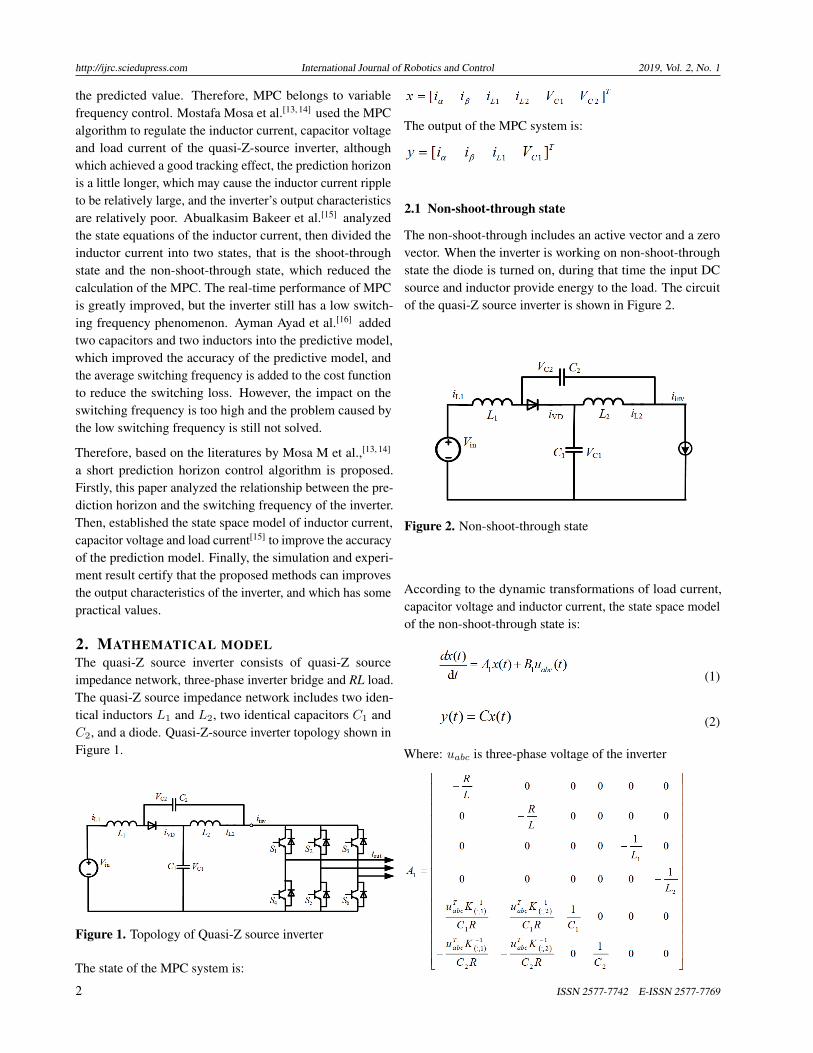
The non-shoot-through includes an active vector and a zerovector. When the inverter is working on non-shoot-throughstate the diode is turned on, during that time the input DCsource and inductor provide energy to the load. The circuitof the quasi-Z source inverter is shown in Figure 2.
Figure 2. Non-shoot-through state
According to the dynamic transformations of load current,capacitor voltage and inductor current, the state space modelof the non-shoot-through state is:
(1)
(2)
Where: uabc is three-phase voltage of the inverter
2 ISSN 2577-7742 E-ISSN 2577-7769
http://ijrc.sciedupress.com International Journal of Robotics and Control 2019, Vol. 2, No. 1
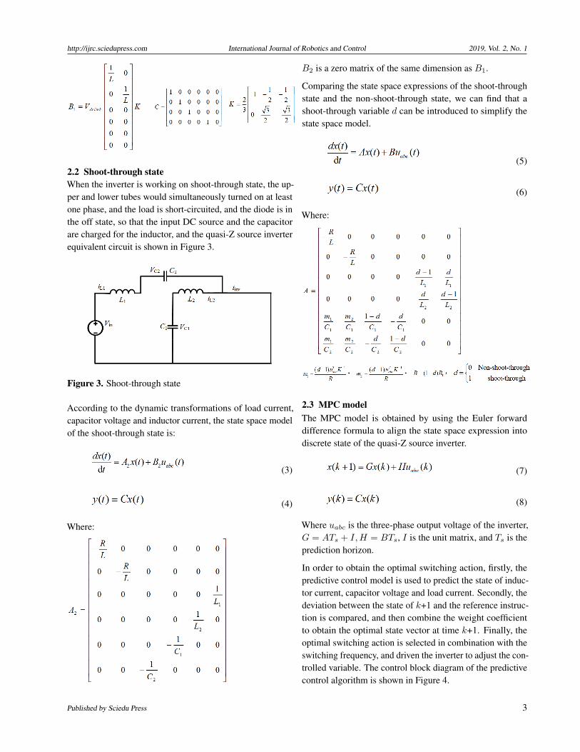
2.2 Shoot-through stateWhen the inverter is working on shoot-through state, the up-per and lower tubes would simultaneously turned on at leastone phase, and the load is short-circuited, and the diode is inthe off state, so that the input DC source and the capacitorare charged for the inductor, and the quasi-Z source inverterequivalent circuit is shown in Figure 3.
Figure 3. Shoot-through state
According to the dynamic transformations of load current,capacitor voltage and inductor current, the state space modelof the shoot-through state is:
(3)
(4)
Where:
B2 is a zero matrix of the same dimension as B1.
Comparing the state space expressions of the shoot-throughstate and the non-shoot-through state, we can find that ashoot-through variable d can be introduced to simplify thestate space model.
(5)
(6)
Where:
2.3 MPC modelThe MPC model is obtained by using the Euler forwarddifference formula to align the state space expression intodiscrete state of the quasi-Z source inverter.
(7)
(8)
Where uabc is the three-phase output voltage of the inverter,G = ATs + I,H = BTs, I is the unit matrix, and Ts is theprediction horizon.
In order to obtain the optimal switching action, firstly, thepredictive control model is used to predict the state of induc-tor current, capacitor voltage and load current. Secondly, thedeviation between the state of k+1 and the reference instruc-tion is compared, and then combine the weight coefficientto obtain the optimal state vector at time k+1. Finally, theoptimal switching action is selected in combination with theswitching frequency, and driven the inverter to adjust the con-trolled variable. The control block diagram of the predictivecontrol algorithm is shown in Figure 4.
Published by Sciedu Press 3
http://ijrc.sciedupress.com International Journal of Robotics and Control 2019, Vol. 2, No. 1
Figure 4. Shoot-through state
3. INDUCTOR CURRENT RIPPLE ANALYSIS
Predictive control uses the predictive models to predict the in-ductor current, capacitor voltage and load current, so that thecontrolled variable fluctuates around its reference value.[15]
The switching time is the same as the prediction horizon Ts,during that time output only one voltage vector, if there areno additional constraints, the same voltage vector may begenerated for several consecutive switching cycles. There-fore, the predictive control’s switching frequency is varied.
In literatures by Mosa M et al.,[13, 14] the working state ofinductance current is analyzed in detail, and the predictivecontrol algorithm is optimized by inductance current, whichreduces the calculation of predictive control algorithm andachieves good control effect. However, the switching fre-quency is not considered in this paper, so it neglected that
may cause larger inductance current and load current ripple.Based on those two literatures, in this paper, the workingstate of quasi-Z-source inverter is analyzed, and the prob-lems caused by high switching frequency and low switchingfrequency are discussed in detail.
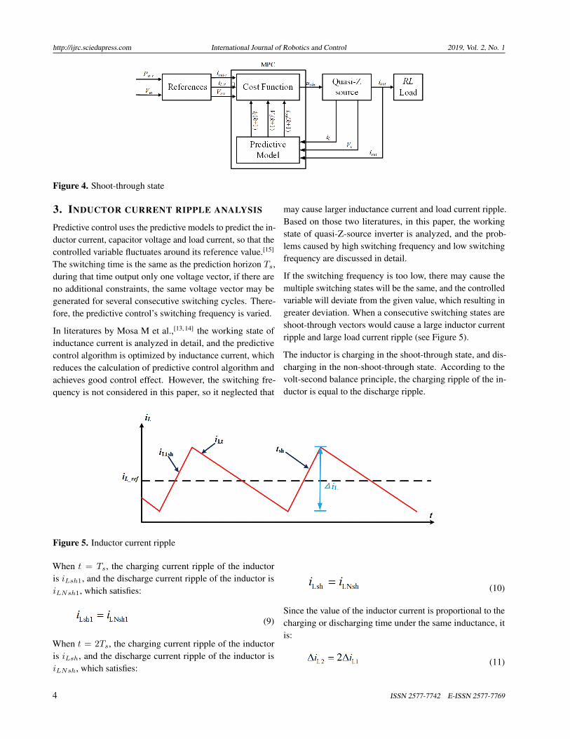
If the switching frequency is too low, there may cause themultiple switching states will be the same, and the controlledvariable will deviate from the given value, which resulting ingreater deviation. When a consecutive switching states areshoot-through vectors would cause a large inductor currentripple and large load current ripple (see Figure 5).
The inductor is charging in the shoot-through state, and dis-charging in the non-shoot-through state. According to thevolt-second balance principle, the charging ripple of the in-ductor is equal to the discharge ripple.
Figure 5. Inductor current ripple
When t = Ts, the charging current ripple of the inductoris iLsh1, and the discharge current ripple of the inductor isiLNsh1, which satisfies:
(9)
When t = 2Ts, the charging current ripple of the inductoris iLsh, and the discharge current ripple of the inductor isiLNsh, which satisfies:
(10)
Since the value of the inductor current is proportional to thecharging or discharging time under the same inductance, itis:
(11)
4 ISSN 2577-7742 E-ISSN 2577-7769

http://ijrc.sciedupress.com International Journal of Robotics and Control 2019, Vol. 2, No. 1
As can be seen that when the prediction horizon is increasedto double the inductor current ripple is also doubled, so thelonger the prediction horizon, the charging and discharginginductor current ripple is greater.
4. SHORT HORIZON MPC4.1 The principle of switching frequency control
In order to improve the switching frequency of the MPC,and overcome the problem that the big inductor current rip-ple and poor load current quality caused by low switchingfrequency. This paper proposed a short horizon predictivecontrol algorithm, on the one hand, which by reducing theprediction horizon Ts to improve the operating frequency ofthe switching device, the action time of the shoot-throughvector and the non-shoot-through vector is greatly shortened,thereby improved the quality of the inverter output wave-form; On the other hand, the high frequency band caused bythe short horizon is limited. When the switching frequencyexceeds the maximum switching frequency, the predictionstate is selected in combination with the historical switchingstate to eliminate the high frequency band. Which not onlyimprove the control effect of the predictive control algorithmbut also the switching loss can be improved.
4.2 Switching frequency control algorithm
When the short horizon predictive control algorithm isadopted, the final applied switching action depends not onlyon the predicted optimal vector, but also on the historicalstate of the switching action. Firstly, the predictive controlmodel is used to obtain the predicted values of all switchstates at time k+1, and then the cost function is used to findthe optimal vector of the switch action. Finally, the switchstate of the switch action is selected in conjunction with thehistorical state of the switch action.
4.2.1 Cost function
In order to obtain the optimal switching action, the weightcoefficients of the cost function need to be matched. Thecost function of the predictive control algorithm is:
(12)
(13)
Where λ is a weight matrix, the larger the value of the weightcoefficient, the greater the adjustment weight, and the greaterthe adjustment of the variable.
4.2.2 Switching frequency control strategyIf the switching action depends on the predicted value, theswitching frequency of the inverter can be increased, butsometime the switching frequency will too high. In this pa-per, when the switching frequency is lower than the limitfrequency, the switching action is obtained by the cost func-tion. When the switching frequency is higher than the limitfrequency the vector is selected by the fewest switching ac-tion of the switch to reduce the switching frequency.
The switching frequency adjustment measures are: the uppertubes of the three-phase inverter bridge are respectively se-lected as: ua, ub, uc and the lower tubes are ua, ub, uc whenthe switch is turned on, the value is 1, and when the switchis off, the value is 0. Set a variable n with an initial value of0. When the switch is switched, the value of n is increasedby 1. The statistical function of the switch action is:
(14)
When the switching frequency is higher than the limit fre-quency, the switching state is determined by the optimalestimate, i.e.:
(15)
When the switching frequency is lower than the limit fre-quency, select the vector by the fewest switching action ofthe switch, i.e.:
(16)
Where N is the statistical number of predictive control, G isthe cost function.
5. SIMULATION AND EXPERIMENTIn order to verify that the short horizon prediction controlalgorithm can significantly improve the control effect of in-ductor current and load current, the simulation system isbuilt by Matlab/Simulink. Then the short horizon predictioncontrol algorithm and the method used in the literature byBakeer A et al.[15] are simulated. The experimental programof two algorithms is written on the CCS development plat-form, and the two algorithms are experimentally verified onthe quasi-Z source experimental platform.
5.1 Simulation analysisThe simulation parameters are: The system input voltage Vin
= 50 V, the parameters of the quasi-Z source network areL1 = L2 = 2 mH, C11 = C2 = 500 µF, load resistance R =10 Ω, load inductance Lload = 8 mH. When D = 0.25 and
Published by Sciedu Press 5

http://ijrc.sciedupress.com International Journal of Robotics and Control 2019, Vol. 2, No. 1
m = 0.7, the average value of the inductor current is 4.76 A,and the values of the bus voltage and the capacitor voltageare only related to the shoot-through-duty ratio D, so thesetwo values remain unchanged. The bus voltage is 100 V andthe capacitor voltage is 75 V.
Figure 6 shows the simulation results of the two algorithm.When the quasi-Z-source working at the steady state, thenchanging the modulation degree m from 0.5 to 0.7. It canbe seen that the controlled variables fluctuating around thereference value. Comparing the inductor simulation result,
it can be seen that both the two algorithm has good trackingeffect, but the short horizon MPC’s inductor current ripplesignificantly smaller. Figure 6(a) shows the simulation re-sults of the inductor current, capacity voltage, load currentand bus voltage of the literature by Bakeer A et al.[15] It canbe seen that the inductor current ripple is 2A. Figure 6(b)shows the simulation results of the inductor current, capacityvoltage, load current and bus voltage of the short horizonprediction control algorithm. It can be seen that the inductorcurrent ripple is 4A.
Figure 6. The overall tracking simulation results
It can be seen from the simulation results that the inductorcurrent can be stably tracked near its references. However,comparing the two algorithms, it can be seen that the induc-tor current ripple is greatly reduced when the short horizonprediction control algorithm is used. It is verified that thelonger the prediction horizon, the larger the ripple of theinductor current, this will cause the bus voltage to drop andthe inverter output waveform to be distorted.
Figure 7 is a simulation result of the load current when the
modulation degree is m = 0.7 It can be seen that the loadcurrent can be tracked near its reference command underboth conditions, and the peak value of the load current is3.93A. Comparing Figure 7(a) and Figure 7(b), it can be seenthat when the prediction horizon is smaller, the ripple of theload current is smaller, and the inverter has a better outputcharacteristics, but the simulation experiments are performedunder ideal conditions, the experimental results don’t seemto be obvious.
Figure 7. Load current simulation result
5.2 Experimental analysisTo further verify the feasibility of the algorithm, using TI’sDSP TMS320F28335 chip as the control core for data pro-cessing. During the experiment, the control effect of the
inductor current, bus voltage and load current was observedwith an oscilloscope. The experimental platform is shown inFigure 8. The experimental conditions and parameters arethe same with the simulation.
6 ISSN 2577-7742 E-ISSN 2577-7769
http://ijrc.sciedupress.com International Journal of Robotics and Control 2019, Vol. 2, No. 1
Figure 8. Experimental platform
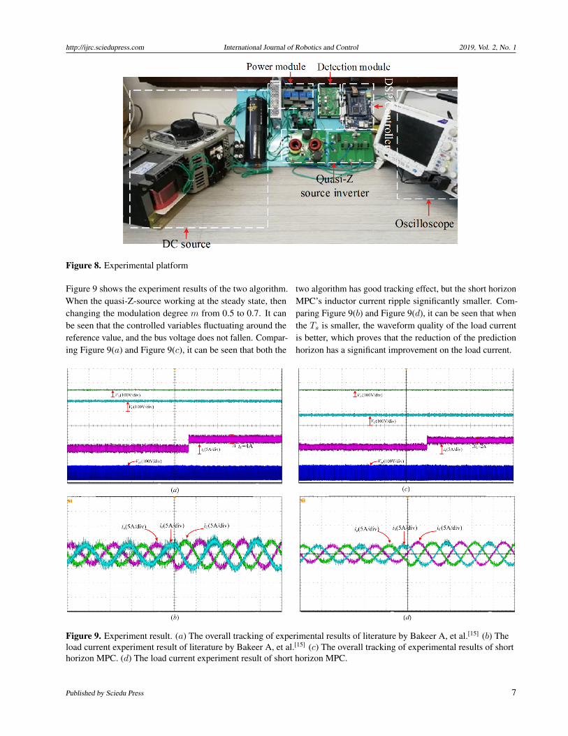
Figure 9 shows the experiment results of the two algorithm.When the quasi-Z-source working at the steady state, thenchanging the modulation degree m from 0.5 to 0.7. It canbe seen that the controlled variables fluctuating around thereference value, and the bus voltage does not fallen. Compar-ing Figure 9(a) and Figure 9(c), it can be seen that both the
two algorithm has good tracking effect, but the short horizonMPC’s inductor current ripple significantly smaller. Com-paring Figure 9(b) and Figure 9(d), it can be seen that whenthe Ts is smaller, the waveform quality of the load currentis better, which proves that the reduction of the predictionhorizon has a significant improvement on the load current.
Figure 9. Experiment result. (a) The overall tracking of experimental results of literature by Bakeer A, et al.[15] (b) Theload current experiment result of literature by Bakeer A, et al.[15] (c) The overall tracking of experimental results of shorthorizon MPC. (d) The load current experiment result of short horizon MPC.
Published by Sciedu Press 7
http://ijrc.sciedupress.com International Journal of Robotics and Control 2019, Vol. 2, No. 1
It can be seen from the experiment that the proposed methodhas better control effect, and which verifies the correctnessand feasibility of the theory.
6. CONCLUSIONIn order to solve the problem that the inductor current ripplewave is large due to the unfixed switching frequency, and theinverter output waveform quality is low, this paper proposeda short horizon predictive control algorithm. The relationshipbetween the predicted horizon and the switching frequency
is studied in detail, and the effects of the inductor current andoutput characteristics of the quasi-Z-source inverter whenthe switching frequency is too low and too high are analyzed.The quasi-Z source inverter is adjusted by taking appropri-ate prediction horizon, and the operating frequency of theinverter is improved by this method. Finally, the simulationand experimental results shows that the method can effec-tively reduce the ripple of the inductor current and improvethe output waveform quality of the inverter.
REFERENCES[1] Peng FZ. Z-source inverter. IEEE Transactions on Industry Appli-
cations. 2003; 39(2): 504-510. https://doi.org/10.1109/TIA.2003.808920
[2] Sun D, Ge B, Zhang H, et al. An energy stored quasi-Z source cas-caded multilevel inverter based photovoltaic power generation system.Applied Power Electronics Conference and Exposition. IEEE. 2014:1747-1751.
[3] Ding X. Single-Stage Control of MPPT and Grid-Connected on Z-Source Inverter PV System. Transactions of China ElectrotechnicalSociety. 2010; 25(4): 122-126.
[4] Arun SPS, Suresh KV, Vinayaka KU. Hybrid wind-solar systemsusing CUK-SEPIC fused converter with quasi-Z-source inverter.Power, Communication and Information Technology Conference.IEEE. 2016: 856-861.
[5] Geyer T, Papafotiou G, Morari M. Model Predictive Control in PowerElectronics: A Hybrid Systems Approach. Decision and Control,2005 and 2005 European Control Conference. Cdc-Ecc ’05. IEEEConference on. IEEE, 2005: 5606-5611.
[6] Yu-Geng XI, De-Wei LI, Shu LIN. Model Predictive Control — Sta-tus and Challenges. Acta Automatica Sinica. 2013; 39(3): 222-236.https://doi.org/10.1016/S1874-1029(13)60024-5
[7] Rodriguez J, Kazmierkowski MP, Espinoza JR, et al. State of the Artof Finite Control Set Model Predictive Control in Power Electronics.IEEE Transactions on Industrial Informatics. 2013; 9(2): 1003-1016.https://doi.org/10.1109/TII.2012.2221469
[8] Vazquez S, Leon JI, Franquelo LG, et al. Model Predictive Control:A Review of Its Applications in Power Electronics. Industrial Elec-tronics Magazine IEEE. 2014; 8(1): 16-31. https://doi.org/10.1109/MIE.2013.2290138
[9] Ayad A, Kennel R. Direct model predictive control of quasi-Z-sourceinverter compared with the traditional PI-based PWM control. Eu-ropean Conference on Power Electronics and Applications. IEEE;2015.
[10] Liu J, Jiang S, Cao D, et al. A Digital Current Control of Quasi-Z-Source Inverter With Battery. IEEE Transactions on IndustrialInformatics. 2013; 9(2): 928-937.
[11] Abdelhakim A, Davari P, Blaabjerg F, et al. Switching Loss Reduc-tion in the Three-Phase Quasi-Z-Source Inverters Utilizing ModifiedSpace Vector Modulation Strategies. IEEE Transactions on PowerElectronics. 2017; PP(99): 1-1.
[12] Lei Q, Cao D, Peng FZ. Novel SVPWM switching pattern for highefficiency 15KW current-fed quasi-Z-source inverter in HEV mo-tor drive application. Applied Power Electronics Conference andExposition. IEEE. 2012: 2407-2420.
[13] Mosa M, Dousoky GM, Abu-Rub H. A novel FPGA implementationof a model predictive controller for SiC-based Quasi-Z-Source invert-ers. Applied Power Electronics Conference and Exposition. IEEE.2014: 1293-1298.
[14] Mosa M, Balog R, Abu-Rub H. High Performance Predictive Controlof Quasi Impedance Source Inverter. IEEE Transactions on PowerElectronics. 2016; PP(99): 1-1.
[15] Bakeer A, Ismeil MA, Orabi M. A Powerful Finite Control Set-Model Predictive Control Algorithm for Quasi Z-Source Inverter.IEEE Transactions on Industrial Informatics. 2016; 12(4): 1371-1379. https://doi.org/10.1109/TII.2016.2569527
[16] Ayad A, Karamanakos P, Kennel R. Direct Model Predictive Cur-rent Control Strategy of Quasi-Z-Source Inverters. IEEE Trans-actions on Power Electronics. 2017; 32(7): 5786-5801. https://doi.org/10.1109/TPEL.2016.2610459
8 ISSN 2577-7742 E-ISSN 2577-7769