Switched Monopulse Radar for Automotive Applications SLR · Switched Monopulse Radar for Automotive...
11
Switched Switched Monopulse Monopulse Radar Radar for Automotive Applications for Automotive Applications SLR SLR Tyco Electronics M/A-COM European Technology & Application Center Schweinfurt, Germany
Transcript of Switched Monopulse Radar for Automotive Applications SLR · Switched Monopulse Radar for Automotive...

Switched Switched MonopulseMonopulse Radar Radar for Automotive Applicationsfor Automotive Applications
SLRSLR
Tyco Electronics M/A-COMEuropean Technology & Application Center
Schweinfurt, Germany

TypicalTypical ApplicationsApplications
Reverse Back-up Aid
Blind Spot Detection
Parking Lot Size Estimation
Parking Aid
Stop & Go Applications
Pre-Crash Sensing
Improved ACC
Functionality
Closing Velocity
Pedestrian Safety

Sensor Sensor ObjectivesObjectivesRadar Parameters
• Radar Principle: Pulse Radar
• Frequency: 24.125 GHz
• Tx Power: <17dBm EIRP
• Bandwidth: 4 GHz @ 20 dB points
• Pulse width: 1.0..1.5 ns
• Pulse Repetition Frequency: ~3 MHz
• Detection Cycle Time: 40 ms
• Antenna Detection Characteristic: ± 8° Elevation 3dB limit
± 65° Azimuth 3dB limit
Object Parameters• Number of Objects: 10
• Parameters Types: Range, Bearing, Velocity, Yaw Rate, Quality, Track ID
Range Parameters• Detection Range: 30m
• Range Performance: 20m (10sqrm target)
• Range (Object) Resolution: 15 cm
• Range Accuracy: 3 cm

Sensor Sensor ObjectivesObjectives ((continuedcontinued))Bearing Parameters
• Bearing Detection Principle: Switched Monopulse
• Bearing Detection Range: ± 40°
• Bearing Accuracy: ± 2° for Bearing Range ±5°
± 5° for Bearing Range ±5°..25°
± 10° for Bearing Range ±25°..40°
Velocity Parameters• Velocity Detection Principle: Range Rate Velocity Measurement
• Velocity Range: ± 100 km/h
• Velocity Accuracy: ± 1 km/h
• Velocity Resolution: 0.05 m/s
Tracking Parameters• Tracking Principle: Extended Kalman Filter Approximation
• Track Initiation: Retrospective Detector (4 in a row)
• Track Kill: 4 consecutive cycles with no detection

PrinciplePrinciple of Operationof Operation
TXAntenna
24 GHzDRO
Time DelayComparision
TimeNormal
Output Signal
High Resolution Radar
RXAntenna
Correlation
Correlation occurs when the pulse traveling time is equal to the internal delay. The resulting IF signal is related to the range of the detected object.
Pulse Radar Correlation
Minimum range: 15cm
Maximum range: 20m (10sqm)
Object Resolution: 15cm
Time Delay Comparison
Pulse traveling time is compared with internal time delay

Block DiagramBlock Diagram
VCO
Power Splitter
RX Switch
TX Switch
IF Out
TX Antenna
PRF ?
DualChannel LNA
Switchable RX Antenna
Signal Processing
Control Circuitry
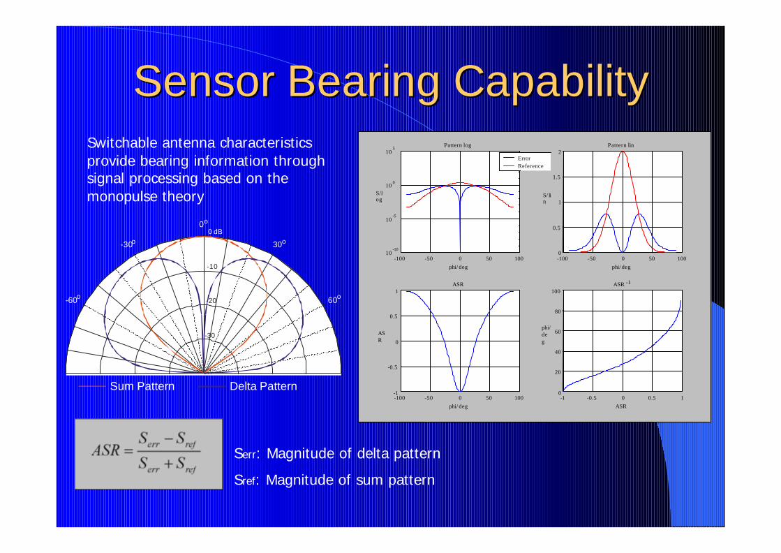
Sensor Bearing Sensor Bearing CapabilityCapabilitySwitchable antenna characteristics provide bearing information through signal processing based on the monopulse theory
Sum Pattern Delta Pattern
-30
-20
-10
0 dB
60o
30o
0o
-30o
-60o
Serr: Magnitude of delta pattern
Sref: Magnitude of sum pattern
-100 -50 0 50 10010
-10
10-5
10 0
105
Pattern log
phi/ deg
S/log
ErrorReference
-100 -50 0 50 1000
0.5
1
1.5
2Pattern lin
phi/ deg
S/ lin
-100 -50 0 50 100-1
-0.5
0
0.5
1ASR
phi/ deg
ASR
-1 -0.5 0 0.5 10
20
40
60
80
100ASR -1
ASR
phi/deg

Typical Angle AccuracyTypical Angle Accuracy Angle accuracy
-40-30-20-10
010203040
-40 -30 -20 -10 0 10 20 30 40
Real Angle
Mea
s A
ng
le
Absolute Angle Error
0
5
10
15
20
-40 -30 -20 -10 0 10 20 30 40
Angle
Ab
s(A
ng
le E
rro
r)

System Impact of Sensor Bearing System Impact of Sensor Bearing Capability Capability
Illustrated is a typical parking situation.
In this case our test car is equipped with 4 sensors that are NOT capable of reporting bearing information on sensor level.
The central processing unit of the radar network has difficulties to resolve the scenario and reports false targets due to ambiguities.

System Impact of Sensor Bearing System Impact of Sensor Bearing Capability Capability
The screenshot beside shows the output of a SINGLE sensor in a similar scenario as illustrated on the slide before.
In conjunction with other sensors of the network redundancy can be achieved leading to a more stable system.

WhyWhy OperatingOperating at 24GHzat 24GHz5.8GHz:•Integration of large antenna sizes into vehicle bumpers is not feasible•Fractional BW for high resolution not realistic
24GHz:•Integration of moderate antenna sizes into vehicle bumpers is feasible•Acceptable attenuation of µWave propagation through bumper material•Fractional BW for high resolution possible•Availability of off-the-shelf components, mature production processes•Economical hybrid design on softboard possible without MMIC‘s
64GHz / 79GHz:•High attenuation of µWave propagation through bumper material•no discrete packaged components available•currently no affordable MMIC‘s available•significant commercial and manufacturing technology deficiency issues
Conclusion:24GHz SRR is the key enabling technology on a short and medium term basis