
SWING-OUT VALVE GUIDE - Akron Brass
18
SWING-OUT VALVE GUIDE 2021
Transcript of SWING-OUT VALVE GUIDE - Akron Brass

SWING-OUT VALVE GUIDE
2 0 2 1

2
AK
RO
N
BR
AS
S
CO
MP
AN
Y
|
80
0.
22
8.
11
61
|
a
kr
on
br
as
s.
co
mS W I N G - O U T V A L V E G U I D E
- 2 -
Style 8810 with R1 Handle
Heavy Duty Brass Swing-Out™ Valves Akron Brass offers a wide variety of apparatus valves to meetthe demands of today’s fire service. All Swing-Out Valves aredesigned for operating pressures of at least 250 psi (17 bar) and meet the NFPA 1901 Standard for valve opening and closing speed control when operated with a gear actuator, electric actuator or Slo-Cloz™. In addition, every valve is factory tested in accordance with current NFPA Standards and backed by a 10 year warranty.
1" and 1.5" Swing-Out Valves
Commonly used on smaller trucks and lower flow applications, the 1” and 1.5” Swing-Out valves are available with a wide
range of adapters and are simple to install and maintain throughout the life of the apparatus.
• A single valve body that will accept a variety of actuators.• HydroMax™ technology: A ball geometry providing superior gating performance and flow characteristics• No lubrication or regular maintenance required• Simple two seated design (no O-Rings to cut or lose during assembly or maintenance)• Wide range of available adapters • High quality brass body cast, machined and assembled at our facility in Wooster, Ohio, USA• Available in 1"- 4" sizes• Ball available in stainless steel or high performance Polymer
HEAVY-DUTY VALVES
*Limited to Manufacture Defects
Style 8815 with TS Handle
Style Size Ball Type Operating Pressure (psi)
Hydrostatic Pressure (psi)
8810 1" Stainless Steel 500 1000
8910 1" Polymer 500 1000
8615 1.5" Stainless Steel 250 500
8815 1.5" Stainless Steel 250 500
8915 1.5" Polymer 250 500
Valve Body
Stainless Steel Ball with HydroMax
High Performance Polymer Ball with HydroMax
Actuator Type Part # # of Holes Length Available Accessories Compatibility
Style Numbers
R1Manual
721236* 2 3 1/2" 8810, 8910 8815, 8915109150 1 3 1/4"
TSManual
78150064 - 5"- 8810, 8910,
8815, 891578150062 - 8"
TSCManual
78150065 - 5"- 8810, 8910,
8815, 891578150087 - 8"
EA
Electric 86158002^ - 7" 8615, 8915
* Standard^Standard 12V
Actuator Options
93333 93335
TM 1477
9327

- 3 -
AK
RO
N
BR
AS
S
CO
MP
AN
Y
R1
TS
Manual Gear
Electric Actuator
Slo-Cloz™Optional SZ
Style Size Ball Type Operating Pressure (psi)
Hydrostatic Pressure (psi)
8620/8820* 2" Stainless Steel 250 500
8920 2" Polymer 250 500
8625/8825* 2.5" Stainless Steel 250 500
8925 2.5" Polymer 250 500
8630/8830* 3" Stainless Steel 250 500
8930 3" Polymer 250 500
8635/8835*# 3" Stainless Steel 250 500
8935# 3" Polymer 250 500 * 8600 series valves for use with Gear, Electric and Air Actuators # 3.5" valves use the same body and ball as the 3" valves but include 3.5" adapters
Valve Body
Actuator Options
Actuator Type Part # # of Holes Length Available Accessories Compatibility
Style Numbers
R1Manual
721238*# 2 6 3/4" 8820, 8825, 8830, 8835, 8920, 8925, 8930, 8935721508# 3 4 1/2"
TSManual
78250568# - 7" 8820, 8825, 8830, 8835, 8920, 8925, 8930, 893578250563*# - 9 1/4"
TSC
Manual78250565*# - 9 1/4"
- 8820, 8825, 8830, 8835, 8920, 8925, 8930, 8935
78250493# - 11"
SZManual 86303002* - 9 1/4" 8620, 8625, 8630, 8925
RS
Manual 86251803** - 12" or 26" - 8625, 8630
GA
Manual Gear
78250463# - - 8620, 8625, 8920, 8925
78300291# - - 8630, 8635, 8930, 8935
EA
Electric
86258006^# - 7" 8620, 8625, 8920, 8925
86308002^# - 7" 8630, 8635, 8930, 8935
* Standard^Standard 12V# More options available** Includes unique valve body
2" - 3.5" Swing-Out Valves
The 2” and larger Swing-Out valves are commonly used across all types of fire apparatus. With the broadest selection
of adapters and options for actuation they have everything you need for your apparatus water flow control.
TM 1477 SC
SC 7593, 7594
Style 8825 with TSC Handle
Style 8820 with R1 Handle
Style 8625 with Electric Actuator
8630
8630
7592
93333 933359327

4
AK
RO
N
BR
AS
S
CO
MP
AN
Y
|
80
0.
22
8.
11
61
|
a
kr
on
br
as
s.
co
mS W I N G - O U T V A L V E G U I D E
- 4 -
4" Swing-Out Valves
Akron's 4" heavy duty valves are designed for tank-to-pump use, deck gun or other higher flow applications and are used with air, gear or electric actuation.
Style 8840 Heavy Duty 4" Swing-Out Valve With Flat Disk Design
• Flat disk concept has spherical seating surface that easily closes and seals on the seat • Short 4" long body length. Can be used on side discharge applications and in restricted pump compartment space • Easy-to-operate sealing system requires less torque to open and close the valve • Reduced gear ratios: - Electric: 25:1 ratio - 8 seconds full open to close - Handwheel 50:1 ratio - 12 1/2 turns • Weight: 36 lbs. (16.3 kg) with electric actuator, less adapters • Wide range of available adapters
Style 8840 with Air Actuator
Air Actuator shown with factory supplied Air Control Valves
Air Actuator (AIR)
Air Actuators operate off the apparatus air supply and are equipped with an emergency override. Designed for full open/close applications only. Units are supplied with two air flow control valves to regulate the opening and closing valve speed to comply with the current NFPA 1901 Standard. • Operates from -40° F to 125° F and requires 100-120 psi air pressure • Available on 4" Swing-Out and all Butterfly Valves • Solenoid and switch not included
Style 8940 4" Swing-Out Valve
• High performance full flow polymer ball• Number of turns for full open/close of gear actuator: 16
Style 8940 with Gear Actuator
Style 8840 with Electric Actuator
Actuator Type Part # # of Holes Length Available Accessories Compatibility
Style Numbers
Air88400874 - 11 1/4"
-8840
79600253 - 13 13/16" 8940
Manual Gear88400852 - - 8840
78400119 - - 8940
Electric88405076 - 12 1/4" 8840
89405000^# - 12 1/4" 8940
Actuator Options
^Standard 12V# More options available
Body Style Size Width Ball Type Operating Pressure (psi)
Hydrostatic Pressure (psi)
8840 4" 4"Flat
Bronze Disk
250 (In Flow Direction)100 (Opposite Flow
Direction)500
8940 4" 6"Round
Polymer Ball
250 500
Valve Body
Swing-Out™ Valve Actuators
8630
93333 933359327
- 5 -
AK
RO
N
BR
AS
S
CO
MP
AN
Y
Manual Handle Accessories
TS
TSC
SZ
R1
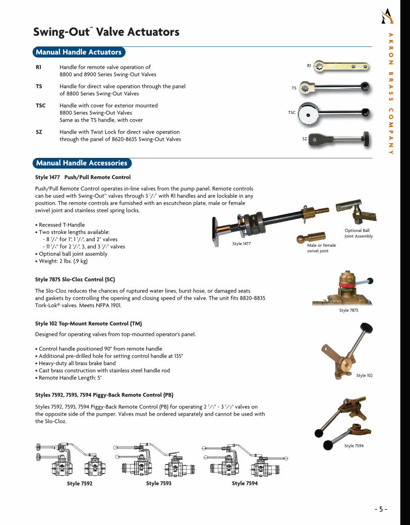
Swing-Out™ Valve ActuatorsManual Handle Actuators
R1 Handle for remote valve operation of 8800 and 8900 Series Swing-Out Valves
TS Handle for direct valve operation through the panel of 8800 Series Swing-Out Valves TSC Handle with cover for exterior mounted 8800 Series Swing-Out Valves Same as the TS handle, with cover
SZ Handle with Twist Lock for direct valve operation through the panel of 8620-8635 Swing-Out Valves
Optional Ball Joint Assembly
Male or female swivel joint
Style 1477
Style 1477 Push/Pull Remote Control
Push/Pull Remote Control operates in-line valves from the pump panel. Remote controls can be used with Swing-Out™ valves through 3 1/2” with R1 handles and are lockable in any position. The remote controls are furnished with an escutcheon plate, male or female swivel joint and stainless steel spring locks.
• Recessed T-Handle • Two stroke lengths available: - 8 1/4" for 1", 1 1/2", and 2" valves - 11 1/4" for 2 1/2", 3, and 3 1/2" valves • Optional ball joint assembly• Weight: 2 lbs. (.9 kg)
Style 7875
Style 7875 Slo-Cloz Control (SC)
The Slo-Cloz reduces the chances of ruptured water lines, burst hose, or damaged seats and gaskets by controlling the opening and closing speed of the valve. The unit fits 8820-8835 Tork-Lok® valves. Meets NFPA 1901.
Styles 7592, 7593, 7594 Piggy-Back Remote Control (PB) for operating 2 1⁄2" - 3 1⁄2" valves on the opposite side of the pumper. Valves must be ordered separately and cannot be used with the Slo-Cloz.
Style 102 Top-Mount Remote Control (TM)
Designed for operating valves from top-mounted operator's panel.
• Control handle positioned 90° from remote handle• Additional pre-drilled hole for setting control handle at 135°• Heavy-duty all brass brake band• Cast brass construction with stainless steel handle rod• Remote Handle Length: 5"
Styles 7592, 7593, 7594 Piggy-Back Remote Control (PB)
Style 102
Style 7592 Style 7593 Style 7594
Style 7594

6
AK
RO
N
BR
AS
S
CO
MP
AN
Y
|
80
0.
22
8.
11
61
|
a
kr
on
br
as
s.
co
mS W I N G - O U T V A L V E G U I D E
- 6 -
8" Heavy Duty Electric Actuator
Electric Actuators (EA)
Akron’s electric actuators are equipped with a magnet in the trunnion to provide more accurate position feedback; requiring no clutches in motor or current limiting. The motor, pressure, and flow sensor connections are all located right on the valve for shorter wire runs and simple installation. The electronics are fully sealed and utilize Deutsch connectors for long life and reliability. A preset speed for opening and closing the valve complies with NFPA 1901 Standard.
Electric Actuator for 1.5” – 3.5” Valves
• Compact size allows for versatile plumbing configurations & easy installation• Manual overrides on two sides • Operates on 12 or 24V (must specify)• Gear drive ratio: 16:1• Patent-pending
Electric Actuator for 4” – 8” Valves
• Manual override • Operates on 12 or 24V (must specify)• Gear drive ratio: - Style 8840: 25:1 - Style 8940 and Butterfly Valves 4” – 8": 64:1• Works with Weco, Keystone and Jamesbury Butterfly Valves (must specify)
Electric Actuator shown mounted on a Swing-Out Valve
Electric Actuator Accessories
Style 86258005 Handwheel Kit for 1.5" - 3.5" Actuator
Handwheel attaches to either side of the actuator for manual override functionality. Must specify when ordering.
Style 9333 Navigator Pro™ 2.0 Electric Valve Controller
Akron's valve controllers provide reliable and accurate valve control with position indication for improved operational effectiveness and safety. Use exclusively with Akron's electric actuator.
• Full color LCD display visible in bright sunlight. Auto dimming capability• Easy-to-navigate setup menu. User programmable presets• Valve name and the discharge color can be programmed on the top bar of the display • USB port on-board. Software for display and motor driver can be easily updated via USB flash drive• Multiple display capability. Multiple displays can be used to control the same valve• Auto open
Style 9335 Navigator Pro 2.0 Controller Electric Valve with Flow and Pressure
All the same features as the 9333, plus the following:
• Optional pressure display: Can be displayed in psi, kPa or bar*• Optional flow display: Can be displayed in gpm or lpm*• Optional CAFS integration: Turn CAFS on and off*• Ensure the most turbulent of flows is accurate with custom calibration of the flow sensor • Totalizer function: Controller will calculate the volume of water flowed, through the paired valve Resets every time the power is cycled to the valve. When networked with other 9325 controllers, total flow across all valves is shown.* Available when flow, pressure or CAFS equipment installed.
Style 9327 Mini Navigator Pro 2.0 Controller Electric Valve with Flow and Pressure
The Navigator Pro Mini is the perfect fit for those tight pump panels where space is at a premium. Measuring only 3.1” tall, it is a full inch shorter than the current Styles 9323 and 9325 Navigator Pro. The width, panel cutout and mounting holes are all identical to the Navigator Pro 2.0 controllers.
• Valve position is indicated with 5 ultra-bright LEDs so you can quickly see the position of the valve• Compatible with the standard Navigator Pro electric actuator• Includes valve open, valve close and one easy-to-program preset button that can be used to send the valve to a pre-programmed position when pressed
Style 9333 Navigator Pro 2.0 Shown in Open Position
Style 9335 Navigator Pro 2.0 with Pressure and Flow
Handwheel Kit
Style 9327 Mini Navigator Pro

- 7 -
AK
RO
N
BR
AS
S
CO
MP
AN
Y
Pyrolite Apparatus Valve 2.5" Swing-Out ValveStyle 7725 2.5" Swing-Out Valve
This lightweight, Pyrolite Swing-Out valve is ideal for use on aerial platforms and features a full flow 2 1/2" waterway.
• Simple two seated design (no o-rings to cut or lose during assembly or maintenance)• No lubrication or regular maintenance required• Designed & tested to exceed NFPA requirements• Weight 9 3/8 lbs. (4.1 kg)• Self-locking Tork-Lok® for easy positioning • Optional Swiveling 90° Elbow (ME1-S)• Optional body with thru holes for direct connection to a manifold
Adapter Options:ME1-S 90° Elbow F1-S Female SwivelP1-S Female NPT F1-SS Female Swivel with StrainerM1-S Male NPT
Style 7725
SAM Control System
SAM is an integrated total water control system that manages your truck’s pump, tank, intakes and discharges. The SAM system replaces your pressure governor and takes care of opening and closing valves based on operator settings. Instead of a complex fire truck pump panel, you can have all your pump controls in a 10" touch-screen display.
Use exclusively with Akron's electrically actuated Swing-Out valves. For more information on how SAM is transforming traditional fire truck pump operations, visit samflows.com.
SAM Control System
Rack and Sector
Rack and Sector Actuator (RS)Minimizes troublesome linkage problems associated with remote handles.
The Rack and Sector Gear Actuator is usable with most pumps (depending on pump panel width). Available on 2 1/2" - 3 1/2" valves. (Requires unique valve body.)
2" - 3 1/2" Manual Gear Actuator
Position Indicator (landscape)
Gear Actuator (GA)Gear Actuator with handwheel is used for smooth, precise operation of valves such as on a deck gun, large diameter side discharge or ladder pipe.
• Handwheel driven worm gear rotates a gear sector for smooth and easy operation under pressure • 2" - 3 1/2" valves have a 4" handwheel • 8840 valves have a 6" handwheel • Number of turns for full open/close: - 2" - 3 1/2" Swing-Out™ valves: 12 1/2 turns - 4" Swing-Out™ valves: 12 1/2 turns • Opening and closing speed complies with the current NFPA standard to minimize effects of water hammer • Helps prevent valve drift and accidental slamming open or closed
Gear Actuator Accessories
Style 8630 Position Indicator
Position Indicator for gear actuated valves showing valve position. Meets NFPA 1901.
• Must specify landscape (side mount) or portrait (top mount) orientation• Size: 3 1/2" x 5 1/2"
Auxiliary Position Indicator
• For use with 2" - 4" Swing-Out valves• Optional (must specify)

BODY DIMENSION KEY
A: Overall body lengthB: From centerline of waterway to centerline of handleC: From centerline of waterway to actuator mounting surfaceD: Bolt circle diameter for valve adapter holesE: Linear dimension for valve adapter holes
D
E
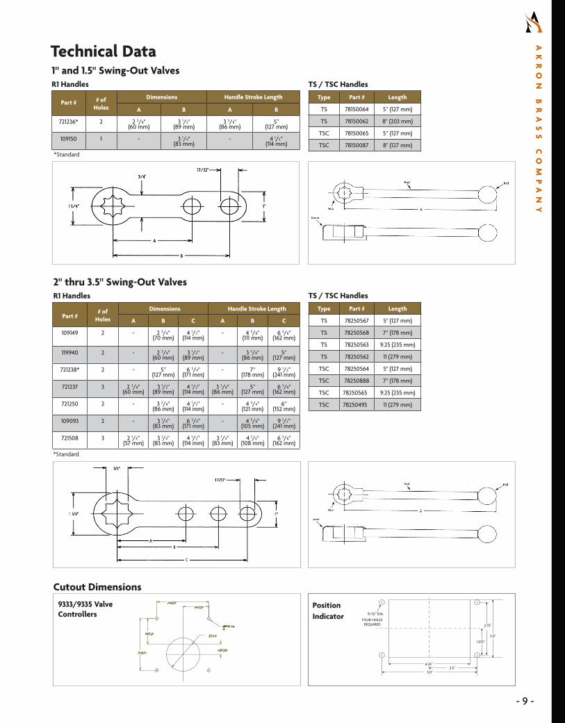
Technical Data
8600, 8800 & 8900 Series Valves
STYLE SIZE AB
C D ER-1 TS/TSC SZ
88108910
1"(25 mm)
1 13/16"(46 mm)
2 25/64"(61 mm)
2 23/32"(69 mm) - 1 13/16"
(46 mm)2 3/4"
(70 mm)2"
(51 mm)861588158915
1 1/2"(38 mm)
2 1/4"(57 mm)
3 3/16"(81 mm)
3 3/64"(77 mm) - 2 1/8"
(54 mm)3 1/2"
(89 mm)2 1/2"
(64 mm)
8620 88208920
2" (51 mm)
3" (76 mm)
3 3/4" (95 mm)
3 3/4"(95 mm)
4 1/8" (105 mm)
2 3/4" (70 mm)
4 1/2” (114 mm)
3 1/4” (82.55 mm)
862588258925
2 1/2" (64 mm)
3 1/2"(89 mm)
4 1/4" (105 mm)
4 1/8" (105 mm)
4 1/2"(114 mm)
3 1/8" (79 mm)
5 3/8” (137 mm)
3 3/4” (95 mm)
8630 8830 8930
3" (76 mm)
4" (102 mm)
4 5/8" (105 mm)
4 1/2" (114 mm)
4 7/8"(124 mm)
3 1/2" (89 mm)
6 1/8” (156 mm)
4 1/4” (107.95 mm)
86358835 8935
3 1/2" (89 mm)
4" (102 mm)
4 5/8" (114 mm)
4 1/2"(114 mm) - 3 1/2"
(89 mm)6 1/8”
(156 mm)4 1/4”
(107.95 mm)
8840 4" (102 mm)
4" (102 mm) - - - 4 1/8"
(105 mm)7 1/16”
(179 mm)5”
(127 mm)
8940 4” (102 mm)
6” (152 mm) - - - 4 1/8"
(105 mm)7 1/16"
(179 mm)5”
(127 mm)
A
Electric Actuator
AirActuator
Gear Actuator with Handwheel
Rack andSector Slo-Cloz™
B
AB
A
C
A
B
centerline of waterway
A
Size A B A B A B C A B 7875 7675
2" 6 39/64" (168mm)
4 1/32" (102 mm) - - 10 1/2"
(267 mm)1 21/32"
(42 mm)4"
(102 mm) - - 1 7/8" (48 mm)
2 3/8" (60 mm)
2 1/2" 6 39/64" (168mm)
4 1/32" (102 mm) - - 10 1/2"
(267 mm)1 21/32"
(42 mm)4"
(102 mm)4 13/16"
(122 mm)3 1/2"
(89 mm)1 7/8"
(48 mm)2 3/8"
(60 mm)
3" 6 39/64" (168mm)
4 1/32" (102 mm) - - 10 1/2"
(267 mm)1 21/32"
(42 mm)4"
(102 mm)4 13/16"
(122 mm)3 7/8"
(98 mm)1 7/8"
(48 mm)2 3/8"
(60 mm)
3 1/2" 6 39/64" (168mm)
4 1/32" (102 mm) - - 10 1/2"
(267 mm)1 21/32"
(42 mm)4"
(102 mm)4 13/16"
(122 mm)3 7/8"
(98 mm)1 7/8"
(48 mm)2 3/8"
(60 mm)
8840 12 1/4" (311 mm)
4 1/8" (105 mm)
5 15/16" (151 mm)
11 1/4" (286 mm)
12 7/16" (316 mm)
3 1/8" (79 mm)
6" (152 mm) - - - -
8940 12 1/4" (311 mm)
4 1/8" (105 mm)
6 3/4" (171 mm)
13 13/16" (351 mm)
12 7/16" (316 mm)
3 1/8" (79 mm)
6" (152 mm) - - - -
8840/8940 only
B
A
A
B
4
2
1
3
Bolts are to be tightened evenly. Tighten opposite bolts in sequence as indicated in the diagram, not adjacent bolts in sequence. After all bolts are initially tightened, repeat the process in the same sequence.
Style Numbers8620-8635, 8810-8840 and 8910-8940
The following is to be used for torquing the hex head bolts which hold the adapters to the body.
VALVE TORQUE
8810/8910 100-120 Inch Pounds
8615/8815/8915 216-240 Inch Pounds
8620/8820/8920 25-30 Foot Pounds
8625/8825/8925 25-30 Foot Pounds
8630/8830/8930 38-40 Foot Pounds
8635/8835/8935 38-40 Foot Pounds
8840/8940 60-70 Foot Pounds
TORQUE REQUIREMENTS
8
AK
RO
N
BR
AS
S
CO
MP
AN
Y
|
80
0.
22
8.
11
61
|
a
kr
on
br
as
s.
co
mS W I N G - O U T V A L V E G U I D E
- 8 -
2.75”
3.0”
2.5”4.25”
5.0”
9/32” DIA.
FOUR HOLESREQUIRED
1.375”
Position Indicator
9333/9335 Valve Controllers
Part ## of
Holes
Dimensions Handle Stroke Length
A B C A B C
109149 2 - 2 3/4" (70 mm)
4 1/2” (114 mm)
- 4 3/8" (111 mm)
6 3/8"(162 mm)
119940 2 - 2 3/8" (60 mm)
3 1/2" (89 mm)
- 3 3/8" (86 mm)
5” (127 mm)
721238* 2 - 5” (127 mm)
6 3/4" (171 mm)
- 7" (178 mm)
9 1/2”(241 mm)
721237 3 2 3/8" (60 mm)
3 1/2" (89 mm)
4 1/2” (114 mm)
3 3/8" (86 mm)
5” (127 mm)
6 3/8"(162 mm)
721250 2 - 3 3/8" (86 mm)
4 1/2” (114 mm)
- 4 3/4" (121 mm)
6” (152 mm)
109093 2 - 3 1/4" (83 mm)
6 3/4" (171 mm)
- 4 5/8" (105 mm)
9 1/2”(241 mm)
721508 3 2 1/4” (57 mm)
3 1/4" (83 mm)
4 1/2” (114 mm)
3 1/4" (83 mm)
4 1/4" (108 mm)
6 3/8"(162 mm)
Technical Data
2" thru 3.5" Swing-Out Valves R1 Handles
Type Part # Length
TS 78150064 5” (127 mm)
TS 78150062 8" (203 mm)
TSC 78150065 5” (127 mm)
TSC 78150087 8" (127 mm)
TS / TSC Handles
Type Part # Length
TS 78250567 5" (127 mm)
TS 78250568 7" (178 mm)
TS 78250563 9.25 (235 mm)
TS 78250562 11 (279 mm)
TSC 78250564 5" (127 mm)
TSC 78250888 7" (178 mm)
TSC 78250565 9.25 (235 mm)
TSC 78250493 11 (279 mm)
Part # # of Holes
Dimensions Handle Stroke Length
A B A B
721236* 2 2 3/8" (60 mm)
3 1/2" (89 mm)
3 3/8" (86 mm)
5” (127 mm)
109150 1 - 3 1/4" (83 mm)
- 4 1/2” (114 mm)
1" and 1.5" Swing-Out ValvesR1 Handles
*Standard
Cutout Dimensions
TS / TSC Handles
*Standard
N=PLQ=N=PLQ=
P=NLO=P=NLO=
N=PLQ=N=PLQ=P=NLO=P=NLO=
@NMJOQ=_l@NMJOQ=_liiqqppQuQu
=QPLSQ==QPLSQ=
- 9 -
AK
RO
N
BR
AS
S
CO
MP
AN
Y

To place an order, state the style number, inlet and outlet adapters needed (always list inlet adapter first), and the type of handle/actuator. All threaded adapters require thread information. Rigid female adapters are available only with tapered pipe thread (NPT). Hose threaded adapters will be supplied with National Hose (NH) thread unless otherwise specified.
Style Description Ball Type Actuators
8615 1.5" Heavy Duty Non-Locking Swing-Out Valve Stainless Steel EA8620 2" Heavy Duty Non-Locking Swing-Out Valve Stainless Steel SZ, EA or GA8625 2 1/2" Heavy Duty Non-Locking Swing-Out Valve Stainless Steel SZ, R/S, EA or GA8630 3" Heavy Duty Non-Locking Swing-Out Valve Stainless Steel SZ, R/S, EA or GA8635 3 1/2" Heavy Duty Non-Locking Swing-Out Valve Stainless Steel GA8810 1" Heavy Duty “Self Locking" Swing-Out Valve Stainless Steel R1, TS, TSC8815 1 1/2" Heavy Duty “Self Locking" Swing-Out Valve Stainless Steel R1, TS, TSC8820 2" Heavy Duty “Self Locking" Swing-Out Valve Stainless Steel R1, TS, or TSC8825 2 1/2" Heavy Duty “Self Locking" Swing-Out Valve Stainless Steel R1, TS, or TSC8830 3" Heavy Duty “Self Locking" Swing-Out Valve Stainless Steel R1, TS, or TSC8835 3 1/2" Heavy Duty “Self Locking" Swing-Out Valve Stainless Steel R1, TS, or TSC8840 4" Heavy Duty “Self Locking" Swing-Out Valve Bronze, Flat Air, EA or GA 8910 1" Heavy Duty “Self Locking" Swing-Out Valve Polymer R1, TS, TSC8915 1 1/2" Heavy Duty Swing-Out Valve Polymer R1, TS, TSC, EA8920 2" Heavy Duty Swing-Out Valve Polymer R1, TS, TSC, EA or GA 8925 2 1/2" Heavy Duty Swing-Out Valve Polymer R1, TS, TSC, SZ, RS, EA or GA 8930 3" Heavy Duty Swing-Out Valve Polymer R1, TS, TSC, EA or GA 8935 3 1/2" Heavy Duty Swing-Out Valve Polymer R1, TS, TSC, EA or GA 8940 4" Heavy Duty Swing-Out Valve Polymer Air, EA or GA
Valve BodySelect style number from chart
Inlet Adapter Select from adapter list
Outlet Adapter Select from adapter list
Enter “CH" to specify chrome option where available. Refer to adapter list for availability. Leave Blank for Standard Cast Finish
Specify Actuator Select from actuator chart above
Specify Actuator Position See chart at right for positions. “N" is standard for manual actuators
Optional Slo-Cloz™ Enter “SC" to specify or leave blank for no Slo-Cloz
P1-S8925 ME1-S CH TS N
Actuator/Handle
Inlet/Pump Side Adapter
Body Outlet Adapter
Optional: Defaults Are Shown
How to Order
INLE
T
INLE
T
OUTL
ET
INLE
T
INLE
T
NOTE: POSITION SHOWN WITH BALL OPEN.
NOTE: POSITION SHOWN WITH BALL OPEN.
POSITION D
POSITION D
POSITION C
POSITION C
POSITION A
POSITION A
POSITION B
POSITION B
Electric Actuator Positions
Gear Actuator Positions
N
C
J
Q
W
X
OPPOSITE PUMP SIDE (OUTLET)
STANDARD
PUMP SIDE (INLET)OPEN VALVETO REMOVE
OPEN VALVETO REMOVE
ALL HANDLE POSITIONS SHOWN ARE WITH THE VALVE CLOSED.
Handle Positions Clock Wise To Open
V
K
M
H
G
P
OPPOSITE PUMP SIDE (OUTLET)PUMP SIDE (INLET)OPEN VALVETO REMOVE
OPEN VALVETO REMOVE
ALL HANDLE POSITIONS SHOWN ARE WITH THE VALVE CLOSED.
Handle Positions Counter Clock Wise To Open
INLE
T
OUTL
ET
INLE
T
OUTL
ET
INLE
T
OUTL
ET
INLE
T
OUTL
ET
OUTL
ETOU
TLET
OUTL
ET
10
AK
RO
N
BR
AS
S
CO
MP
AN
Y
|
80
0.
22
8.
11
61
|
a
kr
on
br
as
s.
co
mS W I N G - O U T V A L V E G U I D E
- 10 -

Rigid Male NPT AdaptersSTYLE
SIZE1" (25 mm) 1 1/2" (38 mm) 2" (50 mm) 2 1/2" (65 mm) 3" (75 mm) 3 1/2" (89 mm) 4" (100 mm)
B
AC
A = Overall length B = Length to centerline of drain hole C = Length to edge of drain boss
BA
A = Valve flange to centerline of elbow B = Pump flange to centerline of elbow
Discharge & Intake Adapters Pump Elbow Adapters
Valve Adapter Dimension KeyKEY
* 1/4" and 3/4" NPT taps
** (2) 3/4" NPT taps
*** 3/4" NPT tap
† 30° Angle
†† 90° Angle
††† Includes Strainer
+ Eccentric flange face
++ Slotted valve flange
+++ 8 holes flange - Use 4
◊ (3) 3/4" NPT Taps
◊◊ Available in Cast or Chrome
# For spacing only. 4 3/8" BCD each end.
### (2) 3/4" NPT Taps and (1) 1" NPT Tap
◀ Non-standard items. May have longer lead times.
M1-S
A 1 21/32" (42 mm) ◀ 1 5/16" (33 mm) 1 5/8" (41 mm) 2" (51 mm) 2 1/16" (52 mm) - 2 21/32"
(75 mm) ◀
B - - - - - - -
C - - - - - - -
M12-S
A - - 1 15/16" (49 mm) ◀ - 3 3/4" (95 mm) ◀ - -
B - - - - - - -
THREAD - - 2 1/2" NPT (64 mm) - 4" NPT (102 mm) - -
Rigid NPT Female Adapters
P1-S
A 1 1/8" (29 mm) 1 1/8" (29 mm) 1 1/4" (32 mm) 1 7/8" (48 mm) 1 7/8" (48 mm) 2" (51 mm) 2 1/8" (54 mm)
B - - - - - - -
C - - - - - - -
* P2-S
A - 3 3/8" (86 mm) 3 1/4" (83 mm) 3 19/32" (91 mm) 3 7/16" (87 mm) 4" (102 mm) 4 5/16" (110 mm)
B - 1 5/8" (41 mm) 1 3/8" (35 mm) 1 3/8" (35 mm) 1 3/8" (35 mm) 1 3/8" (35 mm) 1 3/8" (35 mm)
C - 1 3/8" (35 mm) 2 1/8" (54 mm) 2 1/8" (54 mm) 2 1/8" (54 mm) 2 1/8" (54 mm) 2 19/32" (66 mm)
P10-S
A - 1 1/4" (32 mm) ◀ 2 1/32" (52 mm) ◀ 3 5/16" (84 mm) ◀ - - -
B - - - - - - -
THREAD - 2" NPT (51 mm) 2 1/2" NPT (64 mm) 3" NPT (76 mm) - - -
* P12-S
A - - - - 3 3/4" (95 mm) - -
B - - - - 1 3/8" (35 mm) - -
THREAD - - - - 4" NPT (102 mm) - -
P20-SF
A - - 3 5/32" (80 mm) ◀ 3 7/16" (87 mm) ◀ 4" (102 mm) ◀ - 4" (102 mm) ◀
THREAD - - 2" NPT (51 mm)2 1/2" VIC (64 mm)
2 1/2" NPT (64 mm)3" VIC (76 mm) 3" NPT (76 mm) - 4" NPT (102 mm)
For Flow Meter
◊ ### P30-SCV
A - 5 5/8" (143 mm) ◀ 5 27/32" (148 mm) ◀ 6 1/4" (159 mm) ◀ 7 1/2" (191 mm) ◀ - -
B - 1 21/32" (42 mm) 3 7/8" (98 mm) 4 9/32" (109 mm) 4 15/16" (125 mm) - -
THREAD - 1 1/2" NPT (34 mm)2" VIC (51 mm) 2" NPT (51 mm) 2 1/2" NPT (64 mm) 3" NPT (76 mm) - -
Built-in Check Valve
Valve Adapter Options
- 11 -
AK
RO
N
BR
AS
S
CO
MP
AN
Y

Male Discharge Adapters
STYLE
SIZE
1" (25 mm)
1 1/2" (38 mm)
2" (51 mm)
2 1/2" (64 mm)
3" (76 mm)
4" (102 mm)
◊◊M1-S
A 1 11/16" (42 mm) ◀ 1 5/16" (33 mm) 1 5/8" (41 mm) 2" (51 mm) 1 7/8" (48 mm) 2 21/32"
(67 mm) ◀
B - - - - - -
C - - - - - -
◊◊M2-S
A - - 1 15/16" (49 mm) ◀ - - -
B - - - - - -
THREAD - - 2 1/2" NH (64 mm) - - -
*◊◊M3-S
A - - - 3 3/16" (81 mm) 3 5/16" (84 mm) ◀ 3 19/32" (91 mm)
B - - - 1 3/8" (35 mm) 1 3/8" (35 mm) 1 13/16" (46 mm)
C - - - 2 1/8" (54 mm) 2 1/8" (54 mm) 2 5/8" (67 mm)
*◊◊M4-S
A - - - 5" (127 mm) 5" (127 mm) 8 3/4" (222 mm)
B - - - 1 3/8" (35 mm) 1 3/8" (35 mm) 1 13/16" (46 mm)
C - - - 2 1/8" (54 mm) 2 1/8" (54 mm) 2 15/32" (63 mm)
*◊◊M7-S
A - - - 6 1/2" (165 mm) ◀ - -
B - - - 1 3/8" (35 mm) - -
C - - - 2 1/8" (54 mm) - -
*M8-S
A - - 2 7/8" (73 mm) ◀ - - -
C - - 1 17/64" (32 mm) - - -
THREAD - - 1 1/2" NH (38 mm) - - -
* M10-S
A - - 3 7/32" (82 mm) ◀ - - -
B - - 1 25/64" (35 mm) - - -
THREAD - - 2 1/2" NH (64 mm) - - -
*†◊◊ ME1-S
A - - - 6 5/8" (168 mm) 7" (178 mm) 9 3/4" (248 mm) ◀
B - - - 1 3/8" (35 mm) 1 3/8" (35 mm) 1 5/8" (41 mm)
C - - - 2 1/8" (54 mm) 2 1/8" (54 mm) 2 5/16" (59 mm)
*†◊◊ ME3-S
A - - - 10 5/16" (278 mm) - -
B - - - 1 3/8" (35 mm) - -
C - - - 2 1/8" (54 mm) - -
*†◊◊ ME4-S
A - - - 12 5/16" (313 mm) ◀ - -
B - - - 1 3/8" (35 mm) - -
C - - - 2 1/8" (54 mm) - -
*†◊◊ ME5-S2 1/2"
Thread
A - - - - 6 7/8" (175 mm) ◀ -
B - - - - 1 3/8" (35 mm) -
C - - - - 2 1/8" (54 mm) -
KEY
* 1/4" and 3/4" NPT taps
** (2) 3/4" NPT taps
*** 3/4" NPT tap
† 30° Angle
†† 90° Angle
††† Includes Strainer
+ Eccentric flange face
++ Slotted valve flange
+++ 8 holes flange - Use 4
◊ (3) 3/4" NPT Taps
◊◊ Available in Cast or Chrome
# For spacing only. 4 3/8" BCD each end.
### (2) 3/4" NPT Taps and (1) 1" NPT Tap
◀ Non-standard items. May have longer lead times.
12
AK
RO
N
BR
AS
S
CO
MP
AN
Y
|
80
0.
22
8.
11
61
|
a
kr
on
br
as
s.
co
mS W I N G - O U T V A L V E G U I D E
- 12 -
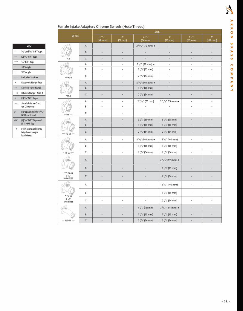
Female Intake Adapters Chrome Swivels (Hose Thread)
STYLE
SIZE
1 1/2" (38 mm)
2" (51 mm)
2 1/2" (64 mm)
3" (76 mm)
3 1/2" (89 mm)
4" (102 mm)
F1-S
A - - 2 15/16" (75 mm) ◀ - - -
B - - - - - -
C - - - - - -
***F2-S
A - - 3 1/2" (89 mm) ◀ - - -
B - - 1 3/8" (35 mm) - - -
C - - 2 1/8" (54 mm) - - -
*F3-S
A - - 5 1/2" (140 mm) ◀ - - -
B - - 1 3/8" (35 mm) - - -
C - - 2 1/8" (54 mm) - - -
F1-SS †††
A - - 2 15/16" (75 mm) 2 15/16" (75 mm) ◀ - -
B - - - - - -
C - - - - - -
*** F2-SS †††
A - - 3 1/2" (89 mm) 3 3/4" (95 mm) - -
B - - 1 3/8" (35 mm) 1 3/8" (35 mm) - -
C - - 2 1/8" (54 mm) 2 1/8" (54 mm) - -
* F3-SS †††
A - - 5 1/2" (140 mm) ◀ 5 1/2" (140 mm) - -
B - - 1 3/8" (35 mm) 1 3/8" (35 mm) - -
C - - 2 1/8" (54 mm) 2 1/8" (54 mm) - -
*** F4-SS 2 1/2"
swivel †††
A - - - 3 13/16" (97 mm) ◀ - -
B - - - 1 3/8" (35 mm) - -
C - - - 2 1/8" (54 mm) - -
* F5-SS2 1/2"
swivel †††
A - - - 5 1/2" (140 mm) - -
B - - - 1 3/8" (35 mm) - -
C - - - 2 1/8" (54 mm) - -
*† FE3-SS †††
A - - 7 1/8" (181 mm) 7 3/4" (197 mm) ◀ - -
B - - 1 3/8" (35 mm) 1 3/8" (35 mm) - -
C - - 2 1/8" (54 mm) 2 1/8" (54 mm) - -
KEY
* 1/4" and 3/4" NPT taps
** (2) 3/4" NPT taps
*** 3/4" NPT tap
† 30° Angle
†† 90° Angle
††† Includes Strainer
+ Eccentric flange face
++ Slotted valve flange
+++ 8 holes flange - Use 4
◊ (3) 3/4" NPT Taps
◊◊ Available in Cast or Chrome
# For spacing only. 4 3/8" BCD each end.
### (2) 3/4" NPT Taps and (1) 1" NPT Tap
◀ Non-standard items. May have longer lead times.
- 13 -
AK
RO
N
BR
AS
S
CO
MP
AN
Y

STYLESIZE
1" (25 mm)
1 1/2" (38 mm)
2" (51 mm)
2 1/2" (64 mm)
3" (76 mm)
3 1/2" (89 mm)
4" (102 mm)
P1-SH
A - - - - 1 15/16" (49 mm) - 2 5/16"
(59 mm) ◀
B - - - - - - -
C - - - - - - -
P12-SH
A - - - - 1 15/16" (49 mm) - -
3" Adapter with 4" Flex Connection
V1-S
A 1 11/16" (43 mm) ◀ 1 3/4" (44 mm) 1 29/32"
(48 mm)1 29/32"
(48 mm)2 3/32"
(53 mm)2 5/32"
(53 mm) ◀2 1/4"
(57 mm)
B - - - - - - -
C - - - - - - -
* V3-S
A - 3 5/16" (84 mm)
3 1/4" (83 mm)
3 3/16" (81 mm)
3 5/16" (84 mm) - 4"
(102 mm)
B - 1 3/8" (35 mm)
1 3/8" (35 mm) 1 3/8" (35 mm) 1 3/8"
(35 mm) - 1 15/16" (49 mm)
C - - - - - - -
* V4-S
A - - - 3 1/2" (89 mm) - - -
B - - - 1 3/8" (35 mm) - - -
C - - - 2 1/8" (54 mm) - - -
2 1/2" (64 mm) with 3" (76 mm) Victaulic
A - - 3 1/4"(83 mm) - - - -
B - - 1 3/8"(35 mm) - - - -
C - - 2"(51 mm) - - - -
◊◊ VT1-S
A - - - - 2 5/32" (52 mm) - 2 11/32"
(60 mm) ◀ 3" (76 mm) has 3" (76 mm) NPT + 4" (102 mm) Victaulic
4" (102 mm) has 4" (102 mm) NPT + 5" (127 mm) Victaulic
†† VE1-S * 2"
*** 1 1/2"
A - - 3 3/4" (95 mm) - - -
B - - 3" (76 mm) - - - -
C - - - - - - -
*†† VE2-S
A - - 5 3/4" (146 mm) ◀ - - - -
B - - 2 31/32" (75 mm) - - - -
C - - - - - - -
d41663
d42017
d42344
dsk2790 d40409V20-SFFor Flow
Meter
A - - 3 3/16" (81 mm) ◀ - - - -
B - - 1 1/4" (32 mm) - - - -
THREAD - - 2" VIC (51 mm) - - - -
◊ ### V30-SCV
A - - 5 27/32" (148 mm)
6 1/4" (159 mm)
7 1/2" (191 mm) ◀ - -
B - - 3 7/8" (98 mm)
4 9/32" (109 mm)
4 15/16" (125 mm) - -
Built-in Check Valve
KEY
* 1/4" and 3/4" NPT taps
** (2) 3/4" NPT taps
*** 3/4" NPT tap
† 30° Angle
†† 90° Angle
††† Includes Strainer
+ Eccentric flange face
++ Slotted valve flange
+++ 8 holes flange - Use 4
◊ (3) 3/4" NPT Taps
◊◊ Available in Cast or Chrome
# For spacing only. 4 3/8" BCD each end.
### (2) 3/4" NPT Taps and (1) 1" NPT Tap
◀ Non-standard items. May have longer lead times.
Grooved Fitting Adapters
* V5-S
Flex Hose Adapters
14
AK
RO
N
BR
AS
S
CO
MP
AN
Y
|
80
0.
22
8.
11
61
|
a
kr
on
br
as
s.
co
mS W I N G - O U T V A L V E G U I D E
- 14 -
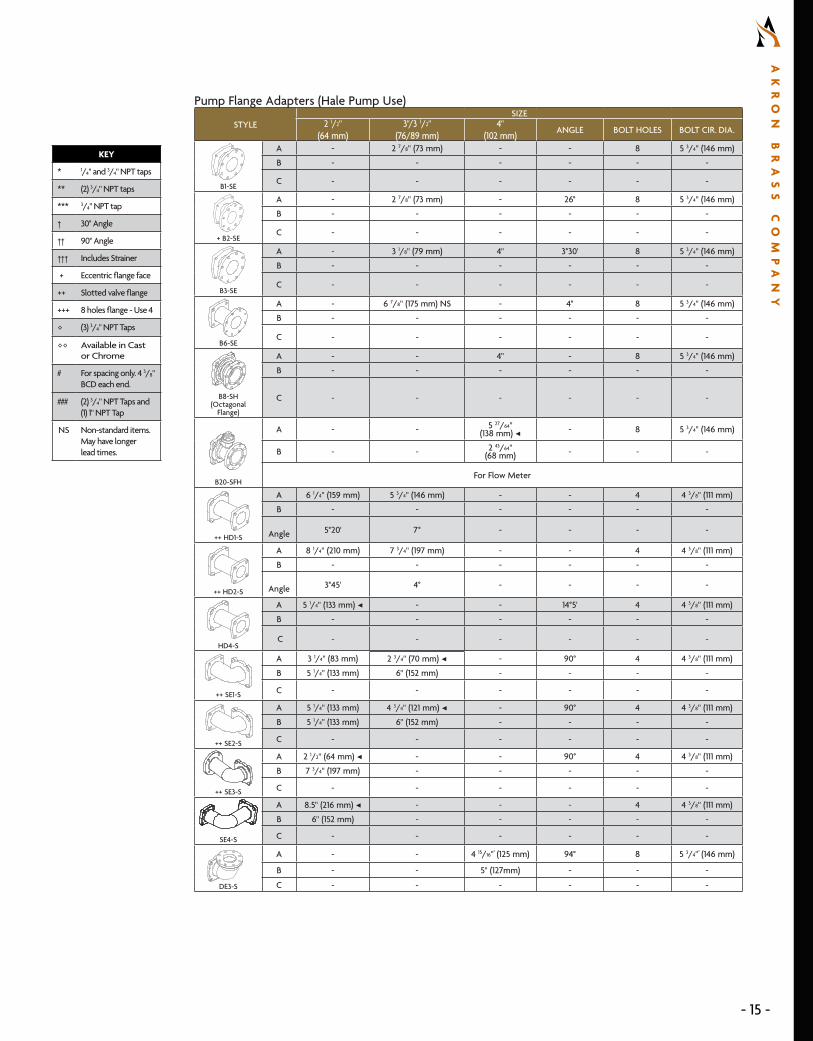
Pump Flange Adapters (Hale Pump Use)
STYLESIZE
2 1/2" (64 mm)
3"/3 1/2" (76/89 mm)
4" (102 mm) ANGLE BOLT HOLES BOLT CIR. DIA.
B1-SE
A - 2 7/8" (73 mm) - - 8 5 3/4" (146 mm)
B - - - - - -
C - - - - - -
+ B2-SE
A - 2 7/8" (73 mm) - 26° 8 5 3/4" (146 mm)
B - - - - - -
C - - - - - -
B3-SE
A - 3 1/8" (79 mm) 4" 3°30' 8 5 3/4" (146 mm)
B - - - - - -
C - - - - - -
B6-SE
A - 6 7/8" (175 mm) NS - 4° 8 5 3/4" (146 mm)
B - - - - - -
C - - - - - -
B8-SH(Octagonal
Flange)
A - - 4" - 8 5 3/4" (146 mm)
B - - - - - -
C - - - - - -d41663
d42017
d42344
dsk2790 d40409
B20-SFH
A - - 5 27/64" (138 mm) ◀ - 8 5 3/4" (146 mm)
B - - 2 43/64" (68 mm) - - -
For Flow Meter
++ HD1-S
A 6 1/4" (159 mm) 5 3/4" (146 mm) - - 4 4 3/8" (111 mm)
B - - - - - -
Angle 5°20' 7° - - - -
++ HD2-S
A 8 1/4" (210 mm) 7 3/4" (197 mm) - - 4 4 3/8" (111 mm)
B - - - - - -
Angle 3°45' 4° - - - -
HD4-S
A 5 1/4" (133 mm) ◀ - - 14°5' 4 4 3/8" (111 mm)
B - - - - - -
C - - - - - -
KEY
* 1/4" and 3/4" NPT taps
** (2) 3/4" NPT taps
*** 3/4" NPT tap
† 30° Angle
†† 90° Angle
††† Includes Strainer
+ Eccentric flange face
++ Slotted valve flange
+++ 8 holes flange - Use 4
◊ (3) 3/4" NPT Taps
◊◊ Available in Cast or Chrome
# For spacing only. 4 3/8" BCD each end.
### (2) 3/4" NPT Taps and (1) 1" NPT Tap
NS Non-standard items. May have longer lead times.
++ SE1-S
A 3 1/4" (83 mm) 2 3/4" (70 mm) ◀ - 90° 4 4 3/8" (111 mm)
B 5 1/4" (133 mm) 6" (152 mm) - - - -
C - - - - - -
++ SE2-S
A 5 1/4" (133 mm) 4 3/4" (121 mm) ◀ - 90° 4 4 3/8" (111 mm)
B 5 1/4" (133 mm) 6" (152 mm) - - - -
C - - - - - -
++ SE3-S
A 2 1/2" (64 mm) ◀ - - 90° 4 4 3/8" (111 mm)
B 7 3/4" (197 mm) - - - - -
C - - - - - -
SE4-S
A 8.5" (216 mm) ◀ - - - 4 4 3/8" (111 mm)
B 6" (152 mm) - - - - -
C - - - - - -
DE3-S
A - - 4 15/16"" (125 mm) 94° 8 5 3/4"" (146 mm)
B - - 5" (127mm) - - -
C - - - - - -
- 15 -
AK
RO
N
BR
AS
S
CO
MP
AN
Y

Pump Flange Adapters (Waterous Pump Use)
STYLE SIZE
2" (51 mm)
2 1/2" (64 mm)
3"/3 1/2" (76/89 mm)
4" (102 mm) ANGLE BOLT HOLE BOLT CIR. DIA.
B1-S
A2 5/8"
(67 mm)2 5/8"
(67 mm)2 7/8"
(73 mm)- - 4
(8 on 2")4 3/8"
(111 mm)B - - - - - - -
C - - - - - - -
B1-SX
A - 2 5/8" (67 mm) - - - 4 slots 4 3/8" (111 mm)B - - - - - - -
C - - - - - - -
+++ B4-S
A - 2 5/8" (67 mm) 2 7/8" (73 mm) ◀ - - 8 4 3/8" (111 mm)B - - - - - - -
C - - - - - - -
B5-S
A - 4 5/8" (117 mm) - - - 4 slots & 4 holes 4 3/8" (111 mm)
A - - 4 1/2" (114 mm) ◀ - - 4 slots 4 3/8" (111 mm)B - - - - - - -
+++ B6-S
A - 6" (152 mm) - - - 8 4 3/8" (111 mm)B - - - - - - -
C - - - - - - -
B7-S
A -5 1/2"
(140 mm) ◀ - - - 4 slots & 4 holes
4 3/8"
(111 mm)
KEY
* 1/4" and 3/4" NPT taps
** (2) 3/4" NPT taps
*** 3/4" NPT tap
† 30° Angle
†† 90° Angle
††† Includes Strainer
+ Eccentric flange face
++ Slotted valve flange
+++ 8 holes flange - Use 4
◊ (3) 3/4" NPT Taps
◊◊ Available in Cast or Chrome
# For spacing only. 4 3/8" BCD each end.
### (2) 3/4" NPT Taps and (1) 1" NPT Tap
◀ Non-standard items. May have longer lead times.
B3-SH
A - -13/16"-1 11/32" (21-34 mm)
- 4° 47 25/32"
(198 mm)B - - - - - - -C - - - - - - -
B3-SH (4")
A - - - 2" Total (51 mm) ◀ 4° 4 7 25/32"
(198 mm)B - - - - - - -C -
+ B2-SW
A - -2 7/8"
(73 mm)- 26° 8
5 1/2" (140 mm)
B - - - - - - -
C - - - - - - -
B3-SW
A - -3 1/8"
(79 mm)- 4° 8
5 1/2" (140 mm)
B - - - - - - -C - - - - - - -
B8-SW
A - - -4"
(102 mm)- 8
5 1/2" (140 mm)
B - - - - - - -
C - - - - - - -
+++ B1-SEW
A - -2 7/8"
(73 mm)- - 8 slots
5 1/2" (140 mm)
WDE1-S
A - - 4 9/16" (112 mm) ◀ - 90° 8
5 1/2" (140 mm)
B - - 4 5/16" (110 mm) - - - -
C - - - - - - -
WDE94-S
A - - - 9 1/2" (241 mm) ◀ 94° 8 5 1/2"
(140 mm)
B - - - 5" (127 mm) - - -
C - - - - - - -
16
AK
RO
N
BR
AS
S
CO
MP
AN
Y
|
80
0.
22
8.
11
61
|
a
kr
on
br
as
s.
co
mS W I N G - O U T V A L V E G U I D E
- 16 -

Pump Flange Adapters General Use
STYLE SIZE
2" (51 mm)
4" (102 mm) ANGLE BOLT HOLE BOLT CIR. DIA.
+++ DE1-S
A 3 3/4" (95 mm) - 90° 8 4 3/8" (111 mm)
B 4 13/16" (122 mm) - - - -
C - - - - -
+++ DE2-S
A 3 3/4" (95 mm) - 90° 8 4 3/8" (111 mm)
B 5 1/2" (140 mm) - - - -
C - - - - -
- 17 -
AK
RO
N
BR
AS
S
CO
MP
AN
Y
Valve Style Basic Service Kit # (O-rings and Seats only)
Complete Service Kit # (O-rings, Seats, and Ball)
8620/8820 9204 91458625/8825 9205 91468630/8830 9206 91478635/8835 9206 9147
8810 9208 88038815 9209 88048840 9166 -8910 9208 8903
8615/8915 9209 89048920 9204 89058925 9205 89068930 9206 89078935 9206 89078940 - 8908
7610/7810 9208 89037615/7815 9209 89047620/7820 9204 89057625/7825 9205 89067630/7835 9206 89077635/7835 9206 8907
7840 - 8908
Valve Repair Kits Generation I and II
Swing-Out™ Valve ID for 2 - 3.5" Generation II
Additional Mounting Plate
8600, 8800 & 8900 Generation II
Valves have “G2” in the Casting
Generation II Stainless Steel Balls with Hydromax™ Technology
are marked with “G2”
The size is cast into the bodies on 2" - 3 1/2" valves
(30 is for both 3" or 3.5")

18
AK
RO
N
BR
AS
S
CO
MP
AN
Y
|
80
0.
22
8.
11
61
|
a
kr
on
br
as
s.
co
mS W I N G - O U T V A L V E G U I D E
- 18 -©2021 Akron Brass Company. All rights reserved. No portion of this can be reproduced without the express written consent of the Akron Brass Company.
Phone+1 (800) 228-1161
Webakronbrass.com
Address343 Venture Blvd., Wooster, OH 44691, USA
Akron Brass i s a Unit of IDEX Corporat ion idexf i resafety.com