Swelling Rock tn Tunnels: Rock Characterization, Effect of … by... · 2014-10-22 · tests. For...
20
Int. J. Rock Mtch. MiJJ. Sci. cl Gtomech. Abstr. Vol. 30, No.4, pp. 361-380, 1993 Printed in Great Britain. All rights reserved 0148-9062/93 $6.00 + 0.00 Copyright © 1993 Pergamon Pn:ss Ltd Swelling Rock tn Tunnels: Rock Characterization, Effect of Horizontal Stresses and Construction Procedures W. STEINERt Tunnels through shales, marls and anhydritic shales experience swelling phenomena. Case histories have been reviewed. Swelling pressures from laboratory tests and associated in situ observations of swelling pressures have been reviewed. Effects of construction procedures and the influence of horizon- tal and lateral stresses have been studied. For shales it was found that laboratory swelling pressures appear to be much higher, often by an order of magnitude than in situ values. The in situ values are below I MPa, many cases indicate only 0.3 MPa or less. In anhydritic shale, where a chemical component influences swelling behaviour, swelling pressures in the range of 2-2.5 MPa have been observed in situ. Laboratory values are usually much higher. Horizontal and lateral stresses play a major role both in laboratory and in situ tests. For in situ stresses from overconsolidation, experience from clay soil has been extrapolated to mesozoic sedimentary rock and calibrated on in situ measurements. Horizontal and lateral stresses must be explicitly considered in swelling rocks, as well as pore-water pressures. Recommendations on improve- ment of laboratory tests are given. INTRODUCTION Tunnels driven through sedimentary rocks with clays, clay shales or anhydritic shales are known to experience swelling phenomena. In the case of clay shales with low to moderate swelling pressures, this results mostly in invert heave. For anhydritic shale rocks, extreme heave and the crushing of strong inverts were observed. Such swelling phenomena were and are very common in mesozoic (jurassic and triassic) rocks of the Jura mountains in eastern France, southwestern Germany and northwestern Switzerland. These phenom- ena were first observed during the construction of the first railway tunnels in the middle of the 19th century [I]. They were again experienced during the construction of railway base tunnels during the first decades of this tBalzari & Schudel AG, Consulting Engineers and Planners, Muri- strasse 60, CH-3000 Bern 16, Switzerland. Editor's Note: Dr Steiner won the Pergamon Prize for the best paper in the Proceedings of the ISRM Eurock '92 Symposium on "Rock Characterization" held at Chester in lhe U.K. in September 1992. Because of the interest in that paper and the fact that lhere was a 6 page limit on contributions to the Eurock '92 Symposium, I invited Dr Steiner to write this more comprehensive paper for this Journal. 361 century [1-3]. They showed up again in the 1960s during the construction of motorway tunnels [4]. A review of swelling phenomena was performed by Ein- stein [5]. Now the railways plan the construction of new high-speed rail lines, requiring new and longer tunnels with elevated requirements on the stability of the track- bed. This study is, in part, the outgrowth of rock mechanics investigations for the Wisenberg Tunnel, which will cross under the main chain of the Jura mountains in Switzerland [6]. Together with the adjacent Adler Tunnel [7] it forms the core piece of a new railway line through the Jura mountains, which will form part of a European north- south high-speed rail link across the Alps. A detailed set of case histories of tunnels in the Jura mountains as well as of some other tunnels that experienced swelling phenomena were collected [8]. This collection provided relevant case histories which have been reviewed, providing fragments of information. Combined with theoretical and ex- perimental knowledge from rock and soil mechanics and our own field and laboratory investigations, this led to new insights into the behaviour of swelling rocks.
Transcript of Swelling Rock tn Tunnels: Rock Characterization, Effect of … by... · 2014-10-22 · tests. For...
Int. J. Rock Mtch. MiJJ. Sci. cl Gtomech. Abstr. Vol. 30, No.4, pp. 361-380, 1993 Printed in Great Britain. All rights reserved
0148-9062/93 $6.00 + 0.00 Copyright © 1993 Pergamon Pn:ss Ltd
Swelling Rock tn Tunnels: Rock Characterization, Effect of Horizontal Stresses and Construction Procedures W. STEINERt
Tunnels through shales, marls and anhydritic shales experience swelling phenomena. Case histories have been reviewed. Swelling pressures from laboratory tests and associated in situ observations of swelling pressures have been reviewed. Effects of construction procedures and the influence of horizontal and lateral stresses have been studied. For shales it was found that laboratory swelling pressures appear to be much higher, often by an order of magnitude than in situ values. The in situ values are below I MPa, many cases indicate only 0.3 MPa or less. In anhydritic shale, where a chemical component influences swelling behaviour, swelling pressures in the range of 2-2.5 MPa have been observed in situ. Laboratory values are usually much higher. Horizontal and lateral stresses play a major role both in laboratory and in situ tests. For in situ stresses from overconsolidation, experience from clay soil has been extrapolated to mesozoic sedimentary rock and calibrated on in situ measurements. Horizontal and lateral stresses must be explicitly considered in swelling rocks, as well as pore-water pressures. Recommendations on improvement of laboratory tests are given.
INTRODUCTION
Tunnels driven through sedimentary rocks with clays, clay shales or anhydritic shales are known to experience swelling phenomena. In the case of clay shales with low to moderate swelling pressures, this results mostly in invert heave. For anhydritic shale rocks, extreme heave and the crushing of strong inverts were observed. Such swelling phenomena were and are very common in mesozoic (jurassic and triassic) rocks of the Jura mountains in eastern France, southwestern Germany and northwestern Switzerland. These phenomena were first observed during the construction of the first railway tunnels in the middle of the 19th century [I]. They were again experienced during the construction of railway base tunnels during the first decades of this
tBalzari & Schudel AG, Consulting Engineers and Planners, Muristrasse 60, CH-3000 Bern 16, Switzerland.
Editor's Note: Dr Steiner won the Pergamon Prize for the best paper in the Proceedings of the ISRM Eurock '92 Symposium on "Rock Characterization" held at Chester in lhe U.K. in September 1992. Because of the interest in that paper and the fact that lhere was a 6 page limit on contributions to the Eurock '92 Symposium, I invited Dr Steiner to write this more comprehensive paper for this Journal.
361
century [1-3]. They showed up again in the 1960s during the construction of motorway tunnels [4]. A review of swelling phenomena was performed by Einstein [5]. Now the railways plan the construction of new high-speed rail lines, requiring new and longer tunnels with elevated requirements on the stability of the trackbed. This study is, in part, the outgrowth of rock mechanics investigations for the Wisenberg Tunnel, which will cross under the main chain of the Jura mountains in Switzerland [6]. Together with the adjacent Adler Tunnel [7] it forms the core piece of a new railway line through the Jura mountains, which will form part of a European north- south high-speed rail link across the Alps.
A detailed set of case histories of tunnels in the Jura mountains as well as of some other tunnels that experienced swelling phenomena were collected [8]. This collection provided relevant case histories which have been reviewed, providing fragments of information. Combined with theoretical and experimental knowledge from rock and soil mechanics and our own field and laboratory investigations, this led to new insights into the behaviour of swelling rocks.
. '
362 STEINER: SWELLING ROCK AND HORIZONTAL STRESSES
Geologic Age (German)
Quart or
Tertior
Maim
Dogger
German (Swiss) Name of unit
Ouortor
Miozoen
E ozoen
Sequonkolk
Argovien
Collovien
Houptrogenstein
Unterer Dogger
Opolinuston
Translated Name (with rock types)
Q uorternory
Miocene
Eocene
Sequon (Limestone)
. (Sholes to sholy Argovren Limestone)
Collovien <Sholes)
Oolithic Limestone
Lower Do er (Shale to sholy gg sandstones)
Opolinus shale
Geologic Age
Quarternary
Tertiary
u ·Ul
Ul <r a: :::>
' u 0
Lias= ~~-----------+--~~L---------------~------------ ~ Oberer Keuper
Keuper Gipskeuper
Upper Keuper
(Anhydritic Gypsum Keuper shale)
~
Ul w ::E
jjjg,~on~~~~L--r--~~Wll~------------~ Ul Ul
::! a: 1-
200m
11/uschelkalk
A
/1
Houptmuschelkolk
Unterer Dolomit
A nhydri I gruppe
Main Limestone
Lower Dolomite lOOm
Anhydrite Group r Anhydritic shales)
Om
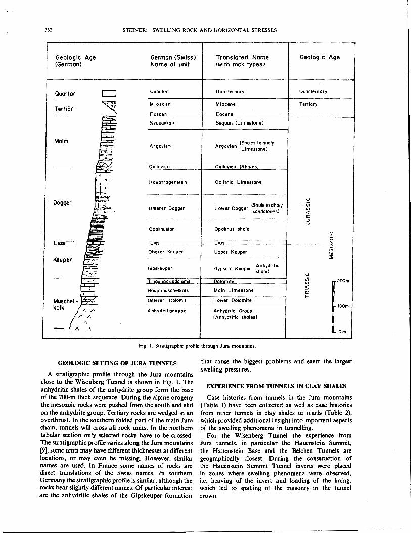
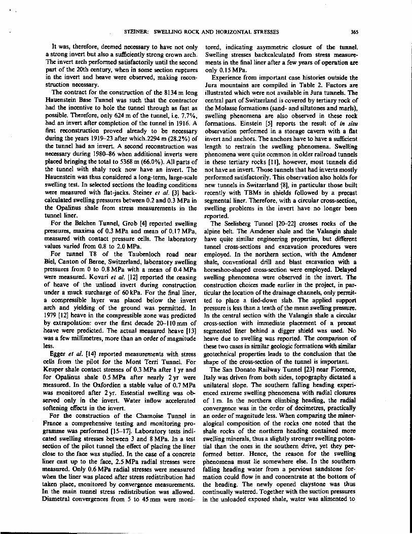
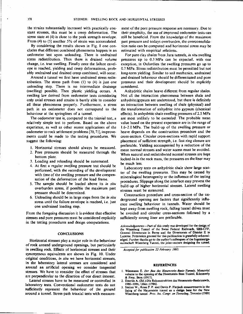
Fig. I. Stratigraphic profile through Jura mountains.
GEOLOGIC SETTING OF JURA TUNNELS
A stratigraphic profile through the Jura mountains close to the Wisenberg Tunnel is shown in Fig. I. The anhydritic shales of the anhydrite group form the base of the 700-m thick sequence. During the alpine orogeny the mesozoic rocks were pushed from the south and slid on the anhydrite group. Tertiary rocks are wedged in an overthrust. In the southern folded part of the main Jura chain, tunnels will cross all rock units. In the northern tabular section only selected rocks have to be crossed. The stratigraphic profile varies along the Jura mountains [9J, some units may have different thicknesses at different locations, or may even be missing. However, similar names are used. In France some names of rocks are direct translations of the Swiss names. In southern Germany the stratigraphic profile is similar, although the rocks bear slightly different names. Of particular interest are the anhydritic shales of the Gipskeuper formation
that cause the biggest problems and exert the largest swelling pressures.
EXPERIENCE FROM TUNNELS IN CLAY SHALES
Case histories from tunnels in the Jura mountains (Table I) have been collected as well as case histories from other tunnels in clay shales or marls (Table 2), which provided additional insight into important aspects of the swelling phenomena in tunnelling.
For the Wisenberg Tunnel the experience from Jura tunnels, in particular the Hauenstein Summit, the Hauenstein Base and the Belchen Tunnels are geographically closest. During the construction of the Hauenstein Summit Tunnel inverts were placed in zones where swelling phenomena were observed, i.e. heaving of the invert and loading of the lining, which led to spalling of the masonry in the tunnel crown.
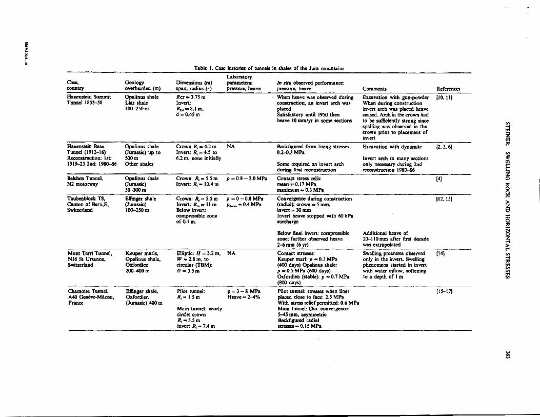
,. :c: ! ~ t " Table I. Case histories of tunnels in shales of the Jura mountains
Laboratory Case. Geology Dimensions (m) parameters: In situ observed performance: country overburden (m) span, radius (r) pressure, heave pressure, heave Comments References
Hauenstein Summit Opalinus shale Rcr= 3.75m When heave was observed during Excavation with gun-powder (10,11] Tunnel 1853-58 Lias shale Invert: construction, an invert arch was When during construction
100-250m R 11, = 8.1 m, placed invert arch was placed heave d =0.45m Satisfactory until 1950 then ceased. Arch in the crown had
heave 10 mm/yr in some sections to be sufficiently strong since en spaDing was observed in the '"':! crown prior to placement of !!! invert z
l'rl
Hauenstein Base Opalinus shale Crown ~ = 4.2 m NA Backfigurcd from lining stresses: Excavation with dynamite (2,3,6] ~
Tunnel (1912-16) (Jurassic) up to Invert: ~ = 4.5 to 0.2~.3MPa en Reconstruction: I st: SOOm 6.2 m, none initially Invert arch in many sections ~ 1919-23 2nd: 1980-86 Other shales Some required an invert arch only necessary during 2nd
l'rl t"'
during first reconstruction reconstruction I 980-86 !: z Belchen Tunnel, Opalinus shale Crown: ~ = 5.5 m p =0.8 -2.0MPa Contact stress cells: (4] 0 N2 motorway (Jurassic) Invert: ~ = 10.4 m mean= 0.17 MPa "' 50-300m maximum -= 0.3 MPa ~ Taubenbloch T8, Effinger shale Crown: R1 = 5.5 m p =0 -0.8MPa Convergence during construction (12,13] ~
> Canton of Bem,E, (Jurassic) Invert: Rn, = II m p,_.=0.4MPa (radial): crown = 5 mm, ~ Switzerland I00-250m Below invert: invert = 30 mm
compressible zone Invert heave stopped with 60 kPa :I: ofO.l m. surcharge 0
"' .... Below final invert: compressible Additional heave of
N 0
zone: further observed heave 20-1 10 mm after first decade ~ 2-<i mm (6 yr) was extrapolated t"'
Mont Terri Tunnel, Keuper marls, Elliptic: H = 3.2 m, NA Contact stresses: Swelling pressures observed (14} en Nl6 St Ursanne, Opalinus shale, W=2.8m, to Keuper marl: p = 0.3 MPa only in the invert. Swelling '"':!
"' Switzerland Oxfordien circular (TBM): (400 days) Opalinus shale: phenomena started in invert l'rl en 200-400m D =3.5m p - 0.5 MPa (600 days) with water inflow, softening en
l'rl Oxfordien (stable): p = 0.7 MPa to a depth of I m tn
(800 days)
Chamoise Tunnel, Effinger shale. Pilot tunnel: p=3-8 MPa Pilot tunnel: stresses when liner (15-17] A40 Geneve-Micon, Oxfordien R1 = 1.5 m Heave=2-4% placed close to face: 2.5 MPa France (Jurassic) 400 m With stress relief permitted: 0.6 MPa
Main tunnel: nearly Main tunnel: Dia. convergence: circle: crown S-45 mm, asymmetric R1=5.5m Backfigurcd radial invert ~ = 7.4 m stresses = 0. I 5 MPa
~ ....
i::
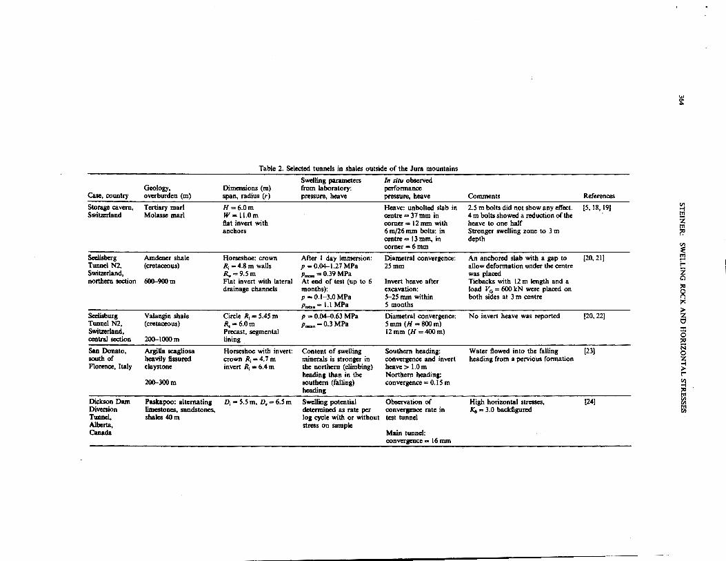
Table 2. Selected tunnels in shales outside of the Jura mountains
Swelling parameters In situ observed Geology, Dimensions (m) from laboratory: performance
Case, country overburden (m) span, radius (r) pressure, heave pressure, heave Comments References
Storage cavern, Tertiary marl H=6.0m Heave: unbolted slab in 2.5 m bolts did not show any effect. [5,18,19) en
Switzerland Molasse marl W= ll.Om centre = 37 mm in 4 m bolts showed a reduction of the ;I
flat invert with corner = 12 mm with heave to one half z t"rt
anchors 6 m/26 mm bolts: in Stronger swelling zone to 3 m ?!' centre= 13 mm, in depth corner-6mm en
~ Seelisberg Amdener shale Horseshoe: crown After I day immersion: Diametral convergence: An anchored slab with a gap to [20,21) m
r" Tuonel N2, (cretaceous) R; = 4.8 m walls p = 0.04-1.27 MPa 25mm allow deformation under the centre r"
Switzerland, R.,=9.5m p....,=0.39MPa was placed z northern section 600-900m Aat invert with lateral At end of test (up to 6 Invert heave after Tiebacks with 12m length and a Cl
drainage channels months): excavation: load V0 = 600 kN were placed on ;:~'
p =0.1-3.0MPa 5-25 mm within both sides at 3 m centre g p.,... = 1.1 MPa 5 months ~
> Seelisburg Valangin shale Circle R; = 5.45 m p = 0.04-0.63 MPa Diametral convergence: No invert heave was reported [20,22) z Tuonel N2, (cretaceous) R,= 6.0m p,_. =0.3MPa 5mm (H =800m) 0 Switzerland, Precast, segmental 12 mm (H = 400 m) ::r:
0 central section 200-IOOOm lining ;:~'
San Donato, Argilla scagliosa Horseshoe with invert: Content of swdling Southern heading: Water flowed into the falling [23) i':i 0
south of heavily fissured crown R; = 4.7 m minerals is stronger in convergence and invert heading from a pervious formation z Aorence, Italy claystone invert R; = 6.4 m the northern (climbing) heave> l.Om ~
heading than in the Northern heading: r"
200-300m southern (falling) convergence= 0.15 m en -!
heading ;:~' t"rt
Dickson Dam Paskapoo: alternating D; = 5.5 m, D,= 6.5 m Swelling potential Observation of High horizontal stresses, [24) en en Diversion limestones, sandstones, determined as rate per convergence rate in Ko = 3.0 backfigured ~ Tunnel, shales 40m log cycle with or without test tunnel Alberta, stress on sample Canada Main tunnd:
convergence = 16 mm
STEINER: SWELLING ROCK AND HORIZONTAL STRESSES 36S
It was, therefore, deemed necessary to have not only a strong invert but also a sufficiently strong crown arch. The invert arch performed satisfactorily until the second part of the 20th century, when in some section ruptures in the invert and heave were observed, making reconstruction necessary.
The contract for the construction of the 8134 m long Hauenstein Base Tunnel was such that the contractor had the incentive to hole the tunnel through as fast as possible. Therefore, only 624 m of the tunnel, i.e. 7.7%, had an invert after completion of the tunnel in 1916. A first reconstruction proved already to be necessary during the years 1919-23 after which 2294 m (28.2%) of the tunnel had an invert. A second reconstruction was necessary during 1980--86 when additional inverts were placed bringing the total to 5368 m (66.0%). All parts of the tunnel with shaly rock now have an invert. The Hauenstein was thus considered a long-term, large-scale swelling test. In selected sections the loading conditions were measured with flat-jacks. Steiner et a/. [3) backcalculated swelling pressures between 0.2 and 0.3 MPa in the Opalinus shale from stress measurements in the tunnel liner.
For the Belchen Tunnel, Grob [4) reported swelling pressures, maxima of 0.3 MPa and mean of 0.17 MPa, measured with contact pressure cells. The laboratory values varied from 0.8 to 2.0 MPa.
For tunnel T8 of the Taubenloch road near Biel, Canton of Berne, Switzerland, laboratory swelling pressures from 0 to 0.8 MPa with a mean of 0.4 MPa were measured. Kovari et a/. [12] reported the ceasing of heave of the unlined invert during construction under a muck surcharge of 60 kPa. For the final liner, a compressible layer was placed below the invert arch and yielding of the ground was permitted. In 1979 [12) heave in the compressible zone was predicted by extrapolation: over the first decade 20-110 mm of heave were predicted. The actual measured heave [13) was a few millimetres, more than an order of magnitude less.
Egger et a/. [14] reported measurements with stress cells from the pilot for the Mont Terri Tunnel. For Keuper shale contact stresses of 0.3 MPa after 1 yr and for Opalinus shale 0.5 MPa after nearly 2 yr were measured. In the Oxfordien a stable value of 0. 7 MPa was monitored after 2 yr. Essential swelling was observed only in the invert. Water inflow accelerated softening effects in the invert.
For the construction of the Chamoise Tunnel in France a comprehensive testing and monitoring programme was performed [15-17]. Laboratory tests indicated swelling stresses between 3 and 8 MPa. In a test section of the pilot tunnel the effect of placing the liner close to the face was studied. In the case of a concrete liner cast up to the face, 2.5 MPa radial stresses were measured. Only 0.6 MPa radial stresses were measured when the liner was placed after stress redistribution had taken place, monitored by convergence measurements. In the main tunnel stress redistribution was allowed. Diametral convergences from 5 to 45 mm were moni-
tored, indicating asymmetric closure of the tunnel. Swelling stresses backcalculated from stress measurements in the final liner after a few years of operation are only 0.15 MPa.
Experience from important case histories outside the Jura mountains are compiled in Table 2. Factors are illustrated which were not available in Jura tunnels. The central part of Switzerland is covered by tertiary rock of the Molasse formations (sand- and siltstones and marls), swelling phenomena are also observed in these rock formations. Einstein [5] reports the result of in situ observation performed in a storage cavern with a flat invert and anchors. The anchors have to have a sufficient length to restrain the swelling phenomena. Swelling phenomena were quite common in older railroad tunnels in these tertiary rocks [11], however, most tunnels did not have an invert. Those tunnels that had inverts mostly performed satisfactorily. This observation also holds for new tunnels in Switzerland 18], in particular those built recently with TBMs in shields followed by a precast segmental liner. Therefore, with a circular cross-section, swelling problems in the invert have no longer been reported.
The Seelisberg Tunnel [20-22) crosses rocks of the alpine belt. The Amdener shale and the Valangin shale have quite similar engineering properties, but different tunnel cross-sections and excavation procedures were employed. In the northern section, with the Amdener shale, conventional drill and blast excavation with a horseshoe-shaped cross-section were employed. Delayed swelling phenomena were observed in the invert. The construction choices made earlier in the project, in particular the location of the drainage channels, only permitted to place a tied-down slab. The applied support pressure is less than a tenth of the mean swelling pressure. In the central section with the Valangin shale a circular cross-section with immediate placement of a precast segmented liner behind a digger shield was used. No heave due to swelling was reported. The comparison of these two cases in similar geologic formations with similar geotechnical properties leads to the conclusion that the shape of the cross-section of the tunnel is important.
The San Donato Railway Tunnel [23) near Florence, Italy was driven from both sides, topography dictated a unilateral slope. The southern falling heading experienced extreme swelling phenomena with radial closures of I m. In the northern climbing heading, the radial convergence was in the order of decimetres, practically an order of magnitude less. When comparing the mineralogical composition of the rocks one noted that the shale rocks of the northern heading contained more swelling minerals, thus a slightly stronger swelling potential than the ones in the southern drive, yet they performed better. Hence, the reason for the swelling phenomena must lie somewhere else. In the southern falling heading water from a pervious sandstone formation could flow in and concentrate at the bottom of the heading. The newly opened claystone was thus continually watered. Together with the suction pressures in the unloaded exposed shale, water was alimented to
366 STEINER: SWELLING ROCK AND HORIZONTAL STRESSES
the rock. Thus swelling phenomena must be related to water access and alimentation.
In a diversion tunnel in Canada (24] creep rates were observed and the liner was placed after a sufficiently stable situation was achieved. Also, high horizontal stresses for the shallow tunnel were backfigured.
Based on the above comparisons of laboratory and field measurements, we note a wide discrepancy. The swelling stresses from laboratory tests usually are orders of magnitude larger. The in situ swelling pressures, whether directly measured or backcalculated from liner stresses, vary from 0.1 to 0.3 MPa for clay rocks, with the exception of the Oxfordien. Laboratory tests most likely do not properly reflect the loading conditions a sample undergoes in the field.
From the above observations it becomes evident that swelling behaviour is not only a material property. Other factors play an important role: the cross-section of the tunnel has a significant influence on the swelling phenomena in the tunnel as have construction procedures and water inflow into the tunnel.
TUNNElS IN ANHYDRITIC SHALE
Differences between shales and anhydritic shales
Swelling phenomena are particularly severe in shales containing not only clay minerals and other rock components but also anhydrite. Experiences from tunnels in pure anhydrite show that tunnelling is easy and no severe swelling effects are known from tunnels in pure anhydrite. It may be argued that the surface of pure anhydrite transforms into gypsum which forms a protective coating. This is completely different in mixtures of anhydrite with shales. In the following sections, observed phenomena in laboratory testing from in situ with free heave and large swelling pressures are described. The interaction problem of the chemical process of the gypsumanhydrite transformation with clay swelling shall be discussed in the following sections. At first the basics of the anhydrite-gypsum transformation are discussed.
Basics of anhydrite-gypsum transformation
Gypsum is calcium-sulphate where water is present in the crystal structure. Anhydrite is calcium-sulphate without water. The transformation processes are complex, since pressure, temperature, solution and precipitation play a major role. In the case of a mixture of shale with anhydrite-gypsum, matters are further complicated due to the interaction processes between the different components. The following relations compiled in Table 3 [25,26] summarize the processes for anhydrite and gypsum.
Table 3. Anhydrite-gypsum transformation
Name: Anhydrite and water Gypsum Formula: Weight:
easo4 + 2 H2o .... easo. · 2 HP 136.14g+36g 172.14g
Volume: 46.2 em'+ 36 em3 74.3 em' Density: y = 2.96 t/m3
}' = 2.32 t/m3
In the case where water is alimented from the outside to the anhydrite a volume increase by 61% has to be expected. When anhydrite and water react in a close system a volume reduction of 9.6% should occur. In the rock mass water is most likely alimented, thus the first condition is more likely to occur. The volume actually formed is often larger than the theoretical 61%. This is due to the nature of crystallization of the gypsum; crystal needles with a substantial porosity are formed. The transformation of anhydrite to gypsum can be restrained with a pressure of 1.6 MPa [25]. Gypsum can also be transformed back into anhydrite at 20°C; this reconversion pressure is 80 MPa, i.e. 50 times as high as the restraining pressure. Above 58°C the transformation of gypsum to anhydrite takes place at atmospheric pressure. The transformation processes are thus not the same in both directions.
Existing laboratory tests on anhydritic shales
Results of laboratory investigations on anhydrite and anhydritic shale are compiled in Table 4. The following comments are necessary. Sahores [25] was one of the first to investigate the swelling behaviour of anhydrite in tunnels. Pure massive anhydrite [27] forms a surface layer of impervious gypsum, afterwards swelling stops. This explains the low swelling pressures. In the ground anhydrite water can access the individual grains and the entire mass can swell. The tests from the Belchen Tunnel were the first tests performed on samples from Jurassic rocks in Switzerland [4, 28].
In the testing procedure for the Wagenburg Tunnel in Stuttgart, Henke et a/. [29], always recompressed the sample to its initial height, even with a substantial amount of swelling strain. The obtained "swelling pressure equivalence value" is the stress used to recompress the sample. Since, during the partly restrained (the frame deforms during loading) swelling process some gypsum may have formed, the mechanical reduction of the sample to its original height will try to reconvert some of the gypsum back into anhydrite, which requires a substantially higher pressure. The obtained pressure is thus a combination of restraining and reconversion pressure.
For the Freudenstein Tunnel a stiff frame was used [30, 3 1]. Some samples were prestressed. For other samples the stress was reduced by allowing some strain relief with the effect that the maximum swelling stress was reached again. The measured swelling pressures correspond to three or more times the overburden stress of the samples.
The detailed procedures for the Heslach Tunnel (32,34] are not known. It is only stated that the very rigid frames were used.
Madsen and Niiesch [35, 36] report the highest swelling pressures for an "optimum" clay content of I 0-15%. The strain of the sample, due to loading of the frame of the apparatus, was only compensated during the first days of testing when clay swelling took place. Madsen and Niiesch used water with 2.4 g/1 calcium sulphates.
STEINER: SWELLING ROCK AND HORIZONTAL STRESSES 367
Laboratory swelling tests on samples from the Hauenstein Base Tunnel
For the design of the Wisenberg Tunnel, which in its southern part parallels the Hauenstein Base Tunnel, a horizontal 20-m-long boring from the Hauenstein Base
"' Tunnel was drilled. In the same zone flat-jack measure-8 '? c = ~ ments in the lining were performed. Drilling proved to 2! ~ "' tO ~
..., '? "'
..., be difficult because no water could be used and the rock ;;; ;::::- ;::::- "' 0\ 0 .,.; .. "' "" ~ !::!. !::!. ti."£ !::!. ~ ~ u: ~ was so hard that it presented substantial resistance to
>. hardened metal bits. i: ._ .. Intact core specimens at 1.3, 2.0-2.3 and 3.1-3.5 m
0 E ·e !l !l ~ tE .5 :::0 depth from the tunnel wall were recovered. Seven labora-~ e .. c ~ .. gt tory samples were prepared for swelling tests. From all :::0 " ·a "'
.., Q) -:5 tU
"' ~ c ; "'"'0 ,0 three cores a sample parallel to the drill axis, i.e.
:::0 :::0 §.~ ~]-5 0 "' c .. .E ~"'0~ ·~ ~ ~ perpendicular to the tunnel wall was prepared. From the c.- c c. ~
8. ...,j!8 ""8. ~ two deeper cores, samples were also taken in directions .§ .5 a.~ .5 = :::0 perpendicular to the drill axis. The samples are square = c ~ "' c =ii c. ~ ~·;- ~~ "' ~ < ~ 50 x 50 mm and 20 mm high and were tested with the ._ w.=~ c.~ 0 ~ ~~ ·e ]:..!! ~d. procedure established by Madsen and Niiesch [36]. c 0:::0>. ~ e ~ ·--0 = ... -~
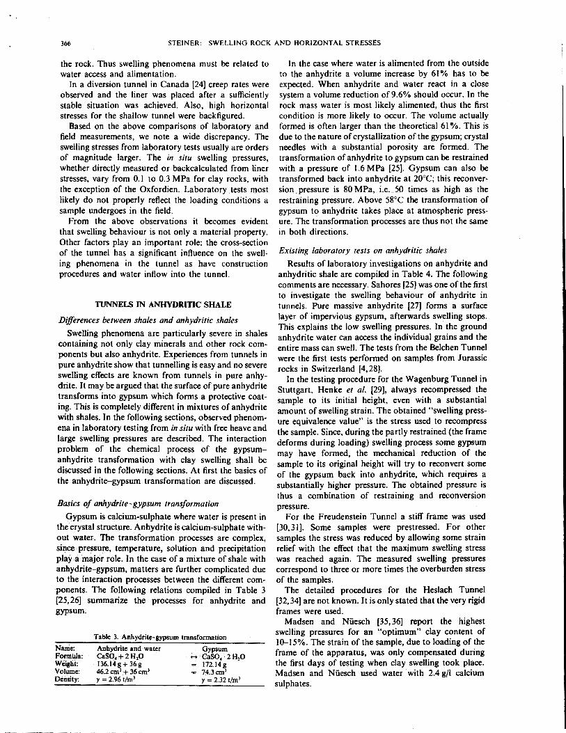
c";i.!! :.C~i .. 0 The swelling pressures developed are presented on 0 > u ~= 1!J
·.;:: !l c g "'C e linear time scale in Fig. 2 for all samples and in Figs 3 c ~
~ c 0 .,g;P- SB
"' .. -~..!! e ';;il]
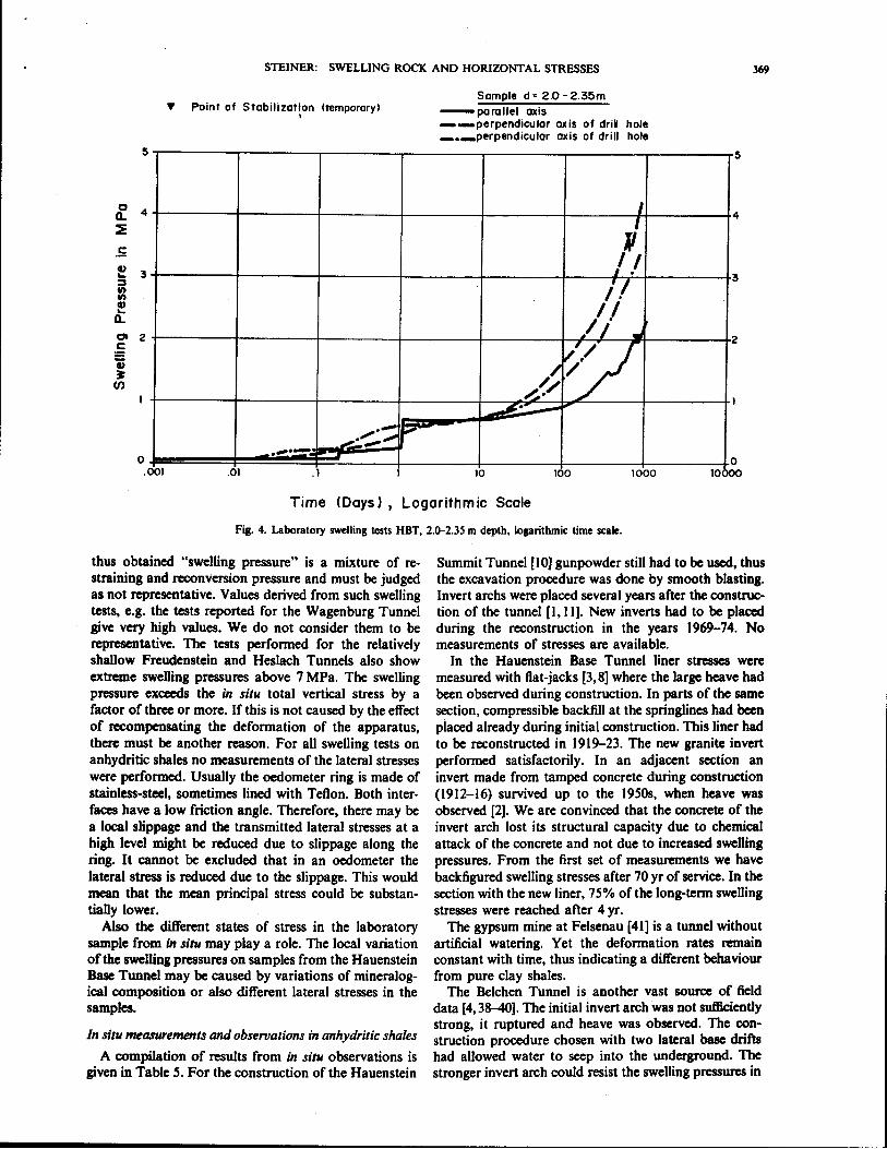
:::0 c and 4 in a logarithmic time scale. ..!! e >. ~ :::0 .58 ~ e "ij ~ u._ f2 ~-~·; .. >. The measured swelling pressure varies considerably
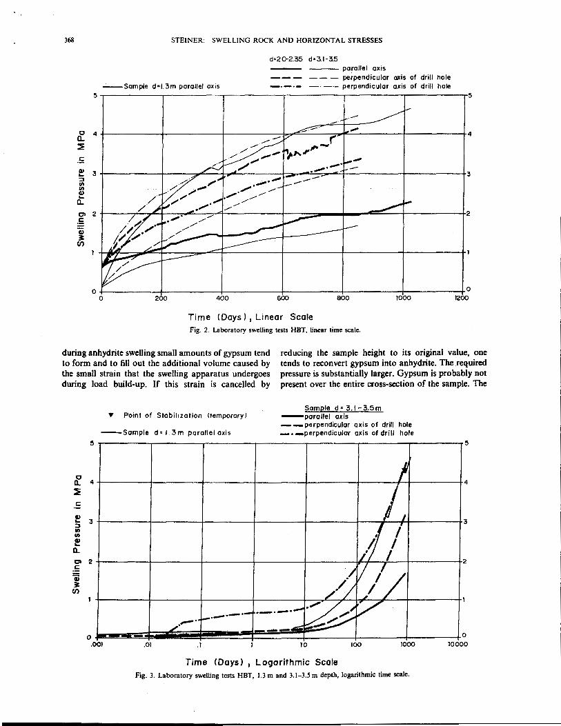
0 ~~ -=e "' "' "' u 0 go c. ~-.:;:: ::E-u -~ .. "' from a minimum value of 1.74 to 4.72 MPa within a ·c distance of only 2m. Three of the;: samples had tempor-~ "' ! >. ..c ~ arily reached a stable swelling pressure: two after more c il "' .... e ] than 2 yr of testing and one slightly before 2 yr. For two c "' 01)~ 0 ~
.. bl)fll ..c u c c c c c of the samples, the swelling pressures started to increase
1!J e 0 :::8. :::8. ! c 0
·.;:: again after about 150 days. The environmental con-0 {ll ~ ~ e " e
"" ·;;;
.; :::0 .. 8 ~ 8 :E ;] .., ditions in the laboratory remained the same. For the
c.- e ... ~Q J!o 1 .. Ill "' 0 .:c .: c third sample, which was thought to stabilize, erratic .. c <!::"' l ..!!8. oof!5 o.~ 0.~ reading of the load cell might be another explanation. i:' e c.e c~u .5 gj .5 !I ·.;:: rl >.
~ .9 -i] e o ;'J"'- ~- fe~ The tests are being continued. At first it was decided to f.'! Ill u -c.~ -e :a. .8 .. c &:..C" 0 :a await stabilization of the swelling pressure and then to ~a ~ll ·.:::·'=~ ~g. ~g. j {Ill!: :z perform mineralogical investigations and comparisons
..j to the original mineralogy and to the mineralogy of free
..!!
.l:l swelling tests made. As a consequence of the renewed "' """
increase in swelling pressures, it was decided to interrupt c'i'
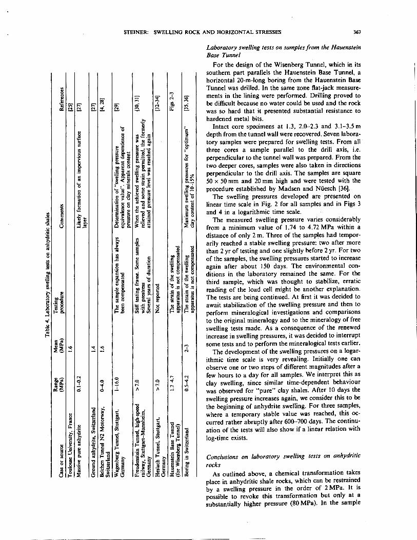
"'"" ..., some tests and to perform the mineralogical tests earlier. "::E ~ ..... ~ I ::E._, "' The development of the swelling pressures on a Iogar-
ithmic time scale is very revealing. Initially one can observe one or two steps of different magnitudes after a
!lh'i' "' 0 ...... "'
few hours to a day for all samples. We interpret this as
~ 0 -o <::! 0 ~ "f clay swelling, since similar time-dependent behaviour c"-~ :r ...... r.:
~::E .,...
~-- 0 A A 0 was observed for "pure" clay shales. After 10 days the swelling pressure increases again, we consider this to be
.., >.
~ la the beginning of anhydrite swelling. For three samples,
u c ~ where a temporary stable value was reached, this oc-"' g i: 'r·i)
t: ~ -~ ~ 'i.e curred rather abruptly after 600-700 days. The continu-
B :::0 ·- c .; u-. u. ..cc ·c ::E Vi "ii~
Cu .., ation of the tests will also show if a linear relation with i- rll '5 c c ..,
"ii :::0 c c :: B "' = I Vi f-o::o ~ 'iii z log-time exists. .. c c~
~A""' c ·c c = ... 1! ~
!;! ~
~ 1l .= ,_.i 1l .. f!' ·a 2! c c 12:1..8 -~ ..c:: c.., c~ c ;:::, :::0 c f!' ·- :::0 = {ll
0 ~; u~ ·§ i .. ~
c. .. :::0>. -= ell >. """>. .5 Conclusions on laboratory swelling tests on anhydritic .. ., .., ci: .De ~ • c '5; §:i 0 > c ~1! ~ "' ., ~~ ... rocks
a ~ ·;;; e l>llf ::o ;r: e .!!e c
~ ~ .!:! ·~ ~0 J:~r; ~0 "' .. 'C
::E 0 .:8v.~ :c@. ~ As outlined above, a chemical transformation takes place in anhydritic shale rocks, which can be restrained by a swelling pressure in the order of 2 MPa. It is possible to revoke this transformation but only at a substantially higher pressure (80 MPa). In the sample
368 STEINER: SWELLING ROCK AND HORIZONTAL STRESSES
d=2.0·2.35 d:3.1·3.5 --- parallel axis
--- -- - perpendicular axis of drill hole --Sample d=l.3m parallel axis -·-·- -- -·- perpendicular axis of drill hole
5~--------~-----------.--------.r----------.-----------.-----------r5
0 4 4 a.. ~
.s Q) 3 3 .... :::1 Ul Ul Q) .... a.. 0> 2 2 .s G) ~
Cf)
+----------~--------+--------~~----------+-----------~-----------+0 200 400 600 800 1000 1200
Time (Days) 1 Linear Scale Fig. 2. Laboratory swelling tests HBT, linear time scale.
during anhydrite swelling small amounts of gypsum tend to form and to fill out the additional volume caused by the small strain that the swelling apparatus undergoes during load build-up. If this strain is cancelled by
reducing the sample height to its original value, one tends to reconvert gypsum into anhydrite. The required pressure is substantially larger. Gypsum is probably not present over the entire cross-section of the sample. The
0 a.. :E c:
f :;, Ul Ul
f a.. 0> c:
'a; ~
Cf)
Y Point of Stabilization !temporary) Sample d=3.1-3.5m
-parallel axis --perpendicular axis of drill hole
-sample d= 1.3m parallel axis -.-perpendicular axis of drill hole 5
4
3
2
0 .001
I
II I I
/~ ,' / V// /.
/•/ ~/ f.-·-·-·- ·-·-·-~·~ y
::::/ /_.,.-· - --- •• ·-.01 .I 10 100 1000
Time CDoys) 1 Logarithmic Scale Fig. 3. Laboratory swelling tests HBT, 1.3 m and 3.1-3.5 m depth, logarithmic time scale.
5
4
3
2
I
0 10000
STEINER: SWELLING ROCK AND HORIZONTAL STRESSES 369
5
.5
f 3 ::::J II) II)
f a.. 0 2 c a; ~
(/)
0 .00 I
't' Point of Stabilization (temporary) 1
.-r-'"'--"~ ..... ... .-·-.01 .1
Sampled& 2.0-2.35m -parallel axis --perpendicular axis of driN hole ___ perpendicular axis of drill hole
I
' /.I il II
~'I .. //
/,•/ v;/
s·- __...
10 100 1000
5
4
3
2
I
0 10 )oo
Time <Days), Logarithmic Scale
Fig. 4. Laboratory swelling tests HBT, 2.0-2.35 m depth. logarithmic time scale.
thus obtained "swelling pressure" is a mixture of restraining and reconversion pressure and must be judged as not representative. Values derived from such swelling tests, e.g. the tests reported for the Wagenburg Tunnel give very high values. We do not consider them to be representative. The tests performed for the relatively shallow Freudenstein and Heslach Tunnels also show extreme swelling pressures above 7 MPa. The swelling pressure exceeds the in situ total vertical stress by a factor of three or more. If this is not caused by the effect of recompensating the deformation of the apparatus, there must be another reason. For all swelling tests on anhydritic shales no measurements of the lateral stresses were performed. Usually the oedometer ring is made of stainless-steel, sometimes lined with Teflon. Both interfaces have a low friction angle. Therefore, there may be a local slippage and the transmitted lateral stresses at a high level might be reduced due to slippage along the ring. It cannot be excluded that in an oedometer the lateral stress is reduced due to the slippage. This would mean that the mean principal stress could be substantially lower.
Also the different states of stress in the laboratory sample from in situ may play a role. The local variation of the swelling pressures on samples from the Hauenstein Base Tunnel may be caused by variations of mineralogical composition or also different lateral stresses in the samples.
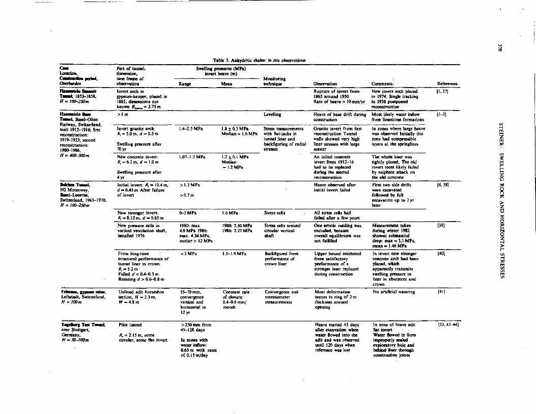
In situ measurements and obseroations in anhydritic shales
A compilation of results from in situ observations is given in Table 5. For the construction of the Hauenstein
Summit Tunnel [10] gunpowder still had to be used, thus the excavation procedure was done by smooth blasting. Invert archs were placed several years after the construction of the tunnel [1, 11]. New inverts had to be placed during the reconstruction in the years 1969-74. No measurements of stresses are available.
In the Hauenstein Base Tunnel liner stresses were measured with fiat-jacks [3,8) where the large heave had been observed during construction. In parts of the same section, compressible backfill at the springlines had been placed already during initial construction. This liner had to be reconstructed in 1919-23. The new granite invert performed satisfactorily. In an adjacent section an invert made from tamped concrete during construction (1912-16) survived up to the 1950s, when heave was observed [2]. We are convinced that the concrete of the invert arch lost its structural capacity due to chemical attack of the concrete and not due to increased swelling pressures. From the first set of measurements we have backfigured swelling stresses after 70 yr of service. In the section with the new liner, 75% of the long-term swelling stresses were reached after 4 yr.
The gypsum mine at Felsenau [41) is a tunnel without artificial watering. Yet the deformation rates remain constant with time, thus indicating a different behaviour from pure clay shales.
The Belchen Tunnel is another vast source of field data [4, 38-40]. The initial invert arch was not sufficiently strong, it ruptured and heave was observed. The construction procedure chosen with two lateral base drifts had allowed water to seep into the underground. The stronger invert arch could resist the swelling pressures in
.... ..... <::>
Table S. Anhydritic shales: ill situ observations
c.. Part of tunnel, Swellina pressures (MPaJ Loc:atioa, dimension, invert heave (m) ~.-.. time fi'8JIIeof Mollitoring ~ observation Range Mean tecbnique Observation Comments References
n.-..s-Jt Invert arch in Rupture of invert from New invert arch placed [1, 37] -r-1, 1853-1858, gypsum-keuper, placed in 1865 around 1950 in 1974. SinJ!)e tracking H= I00-250m 1865, dimensions not Rate of heave> 10 mm/yr in 1938 postponed
known R.....,=3.7Sm reconstruction
H.-telll a- >1m Levelling Heave of base drift during Most likely water inflow (1-3] T-a, BaseJ....Olten construction from limestone formations Railway, Switzerland, {ll
built 1912-1916; first Invert granite arch: 1.4-2.5 MPa 1.8±0.3MPa Stress measurements Granite invert from first In zones where large hes ve -l t'Tl
reconstruction: R; - S.O m, d - 0.5 m Median = 1.6 MPa with ftat-jacks in reconstruction Tunnel was observed Initially this z 1919-1923; second tunnel liner and walls showed very high zone had compressible !"11 reconstruction: Swelling pressure afier backfiguring of radial liner stresses with large layers at the springlines r.:' 1980-1986, 70yr stresses scatter H = 400-500m New concrete invert: 1.07-1.3 MPa 1.2 ±0.1 MPa An initial concrete The whole liner was
{ll
:E R;=6.2m, d= I.Om Median invert from 1912-16 tightly placed. The old !"11
-J.2MPa had to be replaced invert most likely failed r-r
Swelling pressure afier during the second by sulphate attack on z 4yr reconstruction the old concrete Cl .--.T~. Initial invert: R, = 10.4 m, >1.2MPa Heave observed afier First two side drifts (4, 38] " N2 Motorway, d = 0.45 m After failure initial invert failed were excavated g llasei-Luc:erne, of invert >0.7m followed by full ;:.:: Switzerland, 1963-1970, excavation up to 2 yr > H= 100-250m later z
New stronger invert: 0-3MPa 1.6 MPa Stress cells All stress cells had 0 R;=8.t2m, d .. o.85m failed afier a few years :I:
0 New pressure cells in 1980: max 1980: 2.30 MPa Stress cells around One erratic reading was Measurement taken (39) " vertical ventilation shaf\, 4.0 MPa 1986: 1986: 2.27 MPa circular vertical el<duded, because during winter 1982 N installed 1976 max. 4.36 MPa, shaf\ overilll equilibrium was showed substantial ~ outlier> 12 MPa not fulfilled drop: max~ 3.1 MPa,
mean- 1.46 MPa > r-From long-time <3MPa 1.5-1.9MPa Backfigured from Upper bound estimated In invert new stronger (401 V> structural performance of performance of from satisfactory concrete arch had been -l
" tunnel liner in crown crown liner performance of a placed, which !;] R; • 5.2 m stronger liner replaced apparently transmits til
Failed d < 0.4-0.S m durins construction swelling pressure to !"11 Resisting d > 0.6-0.8 m liner in abutment and til
crown
Ftloawl., ~ ane, Unlined adit horseshoe 55-70mm, Constant rate Convergence and Most deformation No artificial watering (41] Leibsladt, Switzerland, section, H = 3.5 m, convergence of dosure: extensometer occurs in ring of 2 m H= lOOm W-4.8m vertical and 0.4-0.6mm/ measurements thickness around
horizontal in month opening 12 yr
~Tesr-r-1, Pilot tunnel >2S0mm from Heave started 45 days In zone of heave adit (33, 42--44] near Stuttlart. 45-120 days afier cxcaYation whc!l ftat invert Germany, R, = 2.15 m, some water ftowed into the Water flowed in from H=1D-100m circular, some ftat invert In zones with adil and was observed improperly sealed
water infto.v: until 120 days when explol'iltory hole and 0.65 m with rates reference was lost beltiDcl liner thrOugh ofO.ISm/day coaStruc:tion joints
Test cavern: elliptic, 0.1~.2MPa Contact stresses The cavern with the The liain& collapsed W= 16.2m, H=9m between shotcrete shotcrete liaing and after water ftowed in
and llfOUnd fibn:glus bolts stood from uploratory for several yean until borins into pund accidental watering several yean after from borin& constnlction
Consequently large heave experienced
u.p -r-1, express Circular: R1 = 5.0 m, <O.SMPa Strains in concrete Observations only for Tunnel excavation with (45} railway, Stuttprt, d = I.Om backfigured from liner about I yr smooth blastin& and Germany, H = 50-S7m stresses in lining trimming of surface with
road header
w..-..T_., North tunnel: pilot half >1m, Invert heave only from [29,46,47 road tunnel, Stuttgart, ellipse, H = 2. 7 m. 1942-1970 water within rockmass Germany. 1942-1957, W=3.0m and air humidity ~ H = 41J-6()m rr1 ...
lateral adit with air <4MPa 2.0MPa Stress cells below Little heave observed Build-up time: 3 yr 'Z rr1
humidity abutment ~
Lateral adit submerged <4.8MPa 3.0MPa Stress cells below large heave observed Build-up time: ~ with water abutment 4 months rr1 Anchored slab 2.8 MPa Neptive arching is [33,48) t"' c possible 'Z Main tunnel W, • 10.5 m Heave>0.7m Since 1982 increased Invert heave: I 85 mm [46,49) Cl During construction unsupported rate of heave: 7 mm/yr Heave of crown: "' invert 70mm ~ Surface heave: SO mm
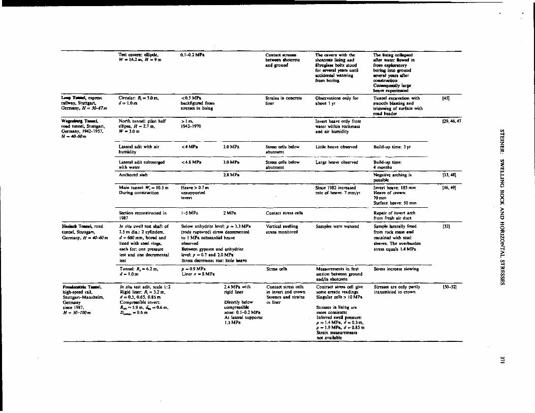
> Section reconstructed in t-5MPa 2MPa Contact stress cells Repair of invert arch 'Z 1987 from fresh air duct t:l
Hcslada T-1. road In situ swell test shaft of Below anhydrite level: p = 3.3 MPa Vertical swelling Samples were watered Sample laterally fnoed [32) :I: 0
tunnel. Stuttgart, 2.5 m dia.: 2 cylinders, (rods ruptured) stress decremented stress monitored from rock mass and "' Germany, H • 41J-6()m d = 600 mm, bored and to I MPa substantial heave restained with steel § lined with steel rings. observed sleeves. The overburden
~ each for: one pressure Between gypsum and anhydrite stress equals 1.4 MPa test and one decrcmental level: p = 0. 7 and 2.0 MPa >
t"' test Stress decrement test: little heave ~ Tunnel: R, = 6.2 m, p-0.9MPa Stress cells Measurements in first Stress increase slowing "' d•l.Om Liner t1 • 8 MPa section between ground rr1
Cll and/in shotc:rete Cll
~ Fn..-..elaT-1, In situ test adit, scale I : 2 2.4 MPa with Contact stress cells Contract stress cell give Stresses are only partly [S0-52) high-speed rail, Rigid liner: R, = 3.2 m, rigid liner in invert and crown some erratic readings. transmitted to crown Stuttgart-Mannhcim, d = 0.3, 0.65, 0.85 m Stresses and strains Singular cells > 10 MPa Germany Compressible invert: Directly below in liner since 1987, R1N = 5.9 m, <4. = 0.6 m, compressible Stresses in lining are H= 50-lOOm D-=0.6m zone: 0.1-{).2 MPa more consistent
At lateral supports: Inferred swell pressure: 1.3 MPa p = 1.4 MPa, d = 0.3m.
p -t.9MPa, d =0.85m Strain measurements not available
... ==
372 STEINER: SWELLING ROCK AND HORIZONTAL STRESSES
the order of 1.6--2.5 MPa. The crown arch remained as initially built. Apparently it is not strong enough and the crown arch fails in compression. Around a vertical shaft pressure cells were placed, which also confirm the existence of the swelling potential above the invert.
Furthermore, unexplained increases in pressures in some stress cells were observed. The erratic extreme value was excluded because the overall equilibrium in the liner would no longer be satisfied. Such phenomena of erratic values have also been observed for stress measurement cells in London clay [53]. Based on these observations caution has to be adopted when interpreting contact stress measurements, in particular with extreme values. The swelling pressures measured with contact stress cells observed at the Belchen and the Freudenstein Tunnels appear to be higher than those backcalculated from structural performance or measurements in the lining. One might postulate a negative arching effect over the pressure cells. The true contact pressure would then, however, be lower. Just by assuming that the stress cell is influenced by an area which is 10% wider and longer on each side, a factor of overestimation of 1.44 is obtained. This argument may apply to the measurements with stress cells and anchored slabs at the Wagenburg Tunnel.
At the Engelberg Test Tunnel large heave was observed during the driving of the pilot tunnel. However, the large test cavern stood supported by a thin shotcrete layer for a substantial time. Low contact stresses were monitored. The liner failed when water inadvertently flowed into the rock mass from the leached gypsum through an exploratory boring drilled several years later. The initial collapse of the liner may also be interpreted as buckling under the water pressure. After the collapse large heave was observed due to unconstrained swelling.
The stresses in the loop tunnel in Stuttgart {45] were obtained for a few years only. The backfigured swelling stresses are very low.
At the Wagenburg Tunnel, heave of the entire tunnel, particularly in the transition zone from gypsum to anhydrite, was observed. The same applies if translated into a heave at the ground surface. Measured swelling pressures in the test adits and in the reconstructed section of the tunnel indicate swelling stresses in the order of 2.0-2.5 MPa taking into account a possible arching effect. In the test adits swelling was 10 times faster when water was alimented to the rock.
The swelling stresses from an in situ swell test at the Heslach Tunnel are more than twice the overburden. Possibly the lateral stresses in the test may no longer correspond to the in situ horizontal stress since the sample was freed from the rock mass. Contact stresses measured in a first section indicated contact stresses of O.SMPa.
At the Freudenstein Tunnel different cross-sections were applied. The test has been in operation since 1987. The invert was artificially watered with sulphate-bearing water from the underground. Only few results have been published. None of the "resisting blocks", i.e. tightly
placed concrete liner of various thickness, failed. The swelling pressures measured with contact cells are in the order of2.0-2.4 MPa. Backfigured swelling stresses from lining stresses are lower. In the crown much lower stresses were measured, indicating that a substantial amount of the load may be transmitted to the ground. In the test sections with a compressible zone, at present lower contact pressures are measured. However, given observations from other cases, we cannot not exclude that higher swelling pressures will develop later.
Conclusions on swelling pressures in anhydritic shales
There are quite huge differences in swelling pressures between laboratory measurements and in situ observations. However, in situ swelling pressures indicate maximum values of 2.5 MPa and mean values between 1.6 and 2.0 MPa. The in situ swelling pressures for anhydritic shale are roughly an order of magnitude larger than those observed in situ for normal shale.--ln cases with a construction procedure that provided immediate support, lower pressures were observed for brief periods. With the present state of knowledge an appropriate construction procedure has to be chosen (no falling heading, TBM excavation or smooth blasting followed by circumferential lining), but it cannot guarantee that substantially smaller swelling pressures have to be supported by the liner. Such careful construction procedures guarantee that tangential stresses are kept locked in the ground and help to prevent swelling.
In several case histories initially large heave was observed, yet still later substantial swelling pressures were observed. We therefore conclude that the placement of a compressible zone does not prevent the build-up of a substantial swelling pressure later in the size as indicated above. The build-up may simply be delayed.
HORIZONTAL STRESSES IN SOIL AND ROCK
The existence of high horizontal stresses in overconsolidated soils is well known [54-59]. One of the first systematic investigations on horizontal stresses in overconsolidated soils was performed by Brooker and Ireland {60]. Their results are also reported in Lambe and Whitman [54]. Observations of fissured clays close to the present ground surface above some level were reported by Skempton [55] for Weald clay in England and by Bjerrum [61} for clays in North America. This fissuring was interpreted as signs of exceeding the shear strength of the soil.
Empirical correlations for overconsolidated soils
The correlations of horizontal stresses to overconsolidation were further developed. Jamiolkowski et a/. {62] and Kulhawy eta/. {58] reported the following empirical relation. The only difference is the formulation of the exponent a:
Ai,(OC) = Ko(NC) · OCR", Ko =horizontal stress ratio = uhju.,
STEINER: SWELLING ROCK AND HORIZONTAL STRESSES 373
OCR= overconsolidation ratio= umv.fu., NC = normally consolidated, OC = overconsolidated,
KQ(NC) =I- sin ,P', a =sin ,P' (Kulhawy et a/. [58]), a = 0.46 ± 0.06 (Jamiolkowski et a/. (62]).
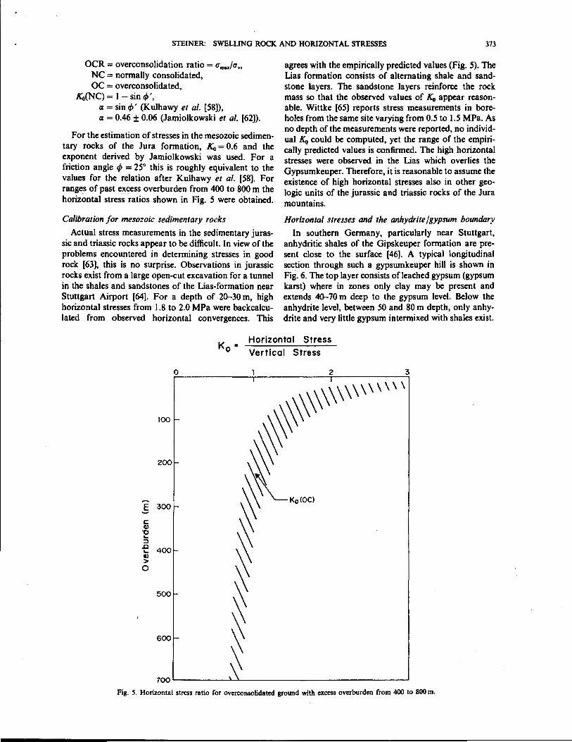
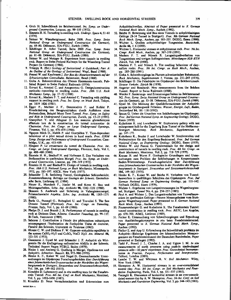
For the estimation of stresses in the mesozoic sedimentary rocks of the Jura formation, Ko = 0.6 and the exponent derived by Jamiolkowski was used. For a friction angle ,P = 25° this is roughly equivalent to the values for the relation after Kulhawy et a/. (58]. For ranges of past excess overburden from 400 to 800 m the horizontal stress ratios shown in Fig. 5 were obtained.
Calibration for mesozoic sedimentary rocks
Actual stress measurements in the sedimentary jurassic and triassic rocks appear to be difficult. In view of the problems encountered in determining stresses in good rock (63], this is no surprise. Observations in jurassic rocks exist from a large open-cut excavation for a tunnel in the shales and sandstones of the Lias-formation near Stuttgart Airport [64]. For a depth of 20-30 m, high horizontal stresses from 1.8 to 2.0 MPa were backcalculated from observed horizontal convergences. This
agrees with the empirically predicted values (Fig. 5). The Lias formation consists of alternating shale and sandstone layers. The sandstone layers reinforce the rock mass so that the observed values of Ko appear reasonable. Wittke [65} reports stress measurements in boreholes from the same site varying from 0.5 to 1.5 MPa. As no depth of the measurements were reported, no individual K0 could be computed, yet the range of the empirically predicted values is confirmed. The high horizontal stresses were observed in the Lias which overlies the Gypsumkeuper. Therefore, it is reasonable to assume the existence of high horizontal stresses also in other geologic units of the jurassic and triassic rocks of the Jura mountains.
Horizontal stresses and the anhydrite /gypsum boundary
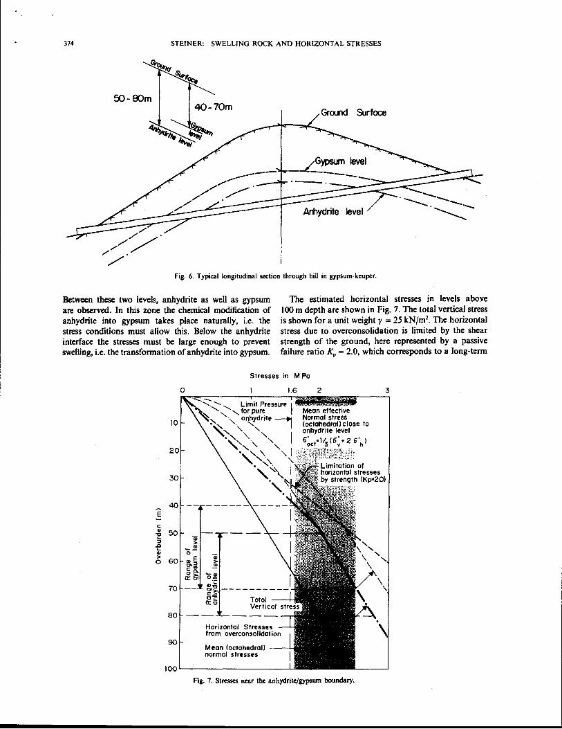
In southern Germany, particularly near Stuttgart, anhydritic shales of the Gipskeuper formation are present close to the surface (46]. A typical longitudinal section through such a gypsumkeuper hill is shown in Fig: 6. The top layer consists ofleached gypsum (gypsum karst) where in zones only clay may be present and extends 40-70 m deep to the gypsum level. Below the anhydrite level, between 50 and 80 m depth, only anhydrite and very little gypsum intermixed with shales exist.
Horizontal Stress Vertical Stress
0 2 3 I
\\\\\\''"" 1- ,\\ f- ~ r- ~Ko{OCl - ~
~ ~
- ~ '~
100
200
E 300 ~
c:: Cl) "0 ._ :::l .0
400 ._ GJ > 0
500
600
700
Fig. 5. Horizontal stress ratio for overconsolidatcd ground with excess overburden from 400 to 800 m.
374 STEINER: SWELLING ROCK AND HORIZONTAL STRESSES
GrOll"ld Surface
Fig. 6. Typical longitudinal section through hill in gypsum-keuper.
Between these two levels, anhydrite as well as gypsum are observed. In this zone the chemical modification of anhydrite into gypsum takes place naturally, i.e. the stress conditions must allow this. Below the anhydrite interface the stresses must be large enough to prevent swelling, i.e. the transformation of anhydrite into gypsum.
The estimated horizontal stresses in levels above I 00 m depth are shown in Fig. 7. The total vertical stress is shown for a unit weighty= 25 kN/m2
• The horizontal stress due to overconsolidation is limited by the shear strength of the ground, here represented by a passive failure ratio KP = 2.0, which corresponds to a long-term
Stresses in M Po
E
c: Cl> ~ ... ::l
.t:l ... Cl> >
0
0
10
30
40 -- -----
50 "ii >
-.!! 0
60 "'E Ol::l c"' gO. a:~
70
80
90
Qi >
..!!
Mean (octahedral! normal stresses
1.6
JQOL-----------------~
2
Mean effective Normal stress (octohedroll close to anhydrite level
6~ct1/3 (6>2 6'hl
Fig. 7. Stresses near the anhydrite/gypsum boundary.
3
1.()
II
~
0
II
~
QJ 0
J:: (/)
QJ (/) "-0 J:
STEINER: SWELLING ROCK AND HORIZONTAL STRESSES
\ \
\ \
\ \
\ \
' ' \ \
0 0 ci 2 N
(DdW)b
0 0
2 2
C! 0 N
IDdWI b
' Iii \
\
' \ Q 0
C! 0
0 0
0
!2 '
I I
I
I I
I I <t
0
!2 I
tr •u
< .o •
I I
I
I
I I
I
~ N '
QJ
0 "-
u
\ \
\ \
\ \
\ \
' \ \
\
' ID
g Q 2 N
(DdW)b
\ ' \
\ \
\ \
\
\
\ \
\
\ \
\
\ \
\ \
ID \
\ \
\
(DdWI b
'
\ \
\
: ! s: ...
lil
' \ Q 0
0
0
!2
I I
I
I I
I
I
I I
I I
0
<
C! 2 '
4 I !2 ,' 0
\ \
0 a.. :IE
0 0
Iii.
I I
I
,' <
Q 0
!2 2
I I
c5 / I I - I <I lo • <
0
!2
I I
I I
I I
I
I
C! 2 I
< 0 0 • •
375
376 STEINER: SWELLING ROCK AND HORIZONTAL STRESSES
friction angle of approx. 20°. The horizontal stress exceeds this shear strength in levels above 50 m depth. The mean normal stress or octahedral normal stress are also shown. Below the anhydrite level the mean normal stress varies from 2.0 to 2.8 MPa at the gypsum level from 1.6 to 2.5 MPa. These values correspond to the swelling pressures obtained from laboratory tests without compensation of the deformation of the apparatus and many of the field measurements. The presence of the anhydrite and gypsum levels at these depths is, therefore, considered no coincidence.
The existence of high horizontal stresses can be inferred from the cracks observed in the rock behind the springlines in the test section of the Engelberg Test Tunnel [44]. It has also been postulated by Spaun [42] and Wichter [34] based on their observations.
The surface heave observed at the Wagenburg Tunnel [47] can thus also be explained. The construction of the Wagenburg Tunnel with its flat invert led to the reduction of the horizontal stresses and as a consequence of the mean normal stresses. This in tum led to the swelling phenomena which produced the surface heave. The anhydrite and gypsum levels were lowered and a new equilibrium had to be reached.
STRESs-PATHS IN THE VICINITY OF TUNNELS
The stress-path is a tool [54] which allows the easy visualization of stress changes in a soil or rock mass.
The Mohr circle is represented by its apex with the coordinates (p, q ):
p = (u1 + u3 )/2 ==(a,+ ah)/2.
q = {u 1 - a3)/2 = (u.- ah)/2.
Here the vertical stress is assumed as the first principal stress and the horizontal stress as the third principal stress. In case the horizontal stress becomes larger than the vertical one, this results in a negative q.
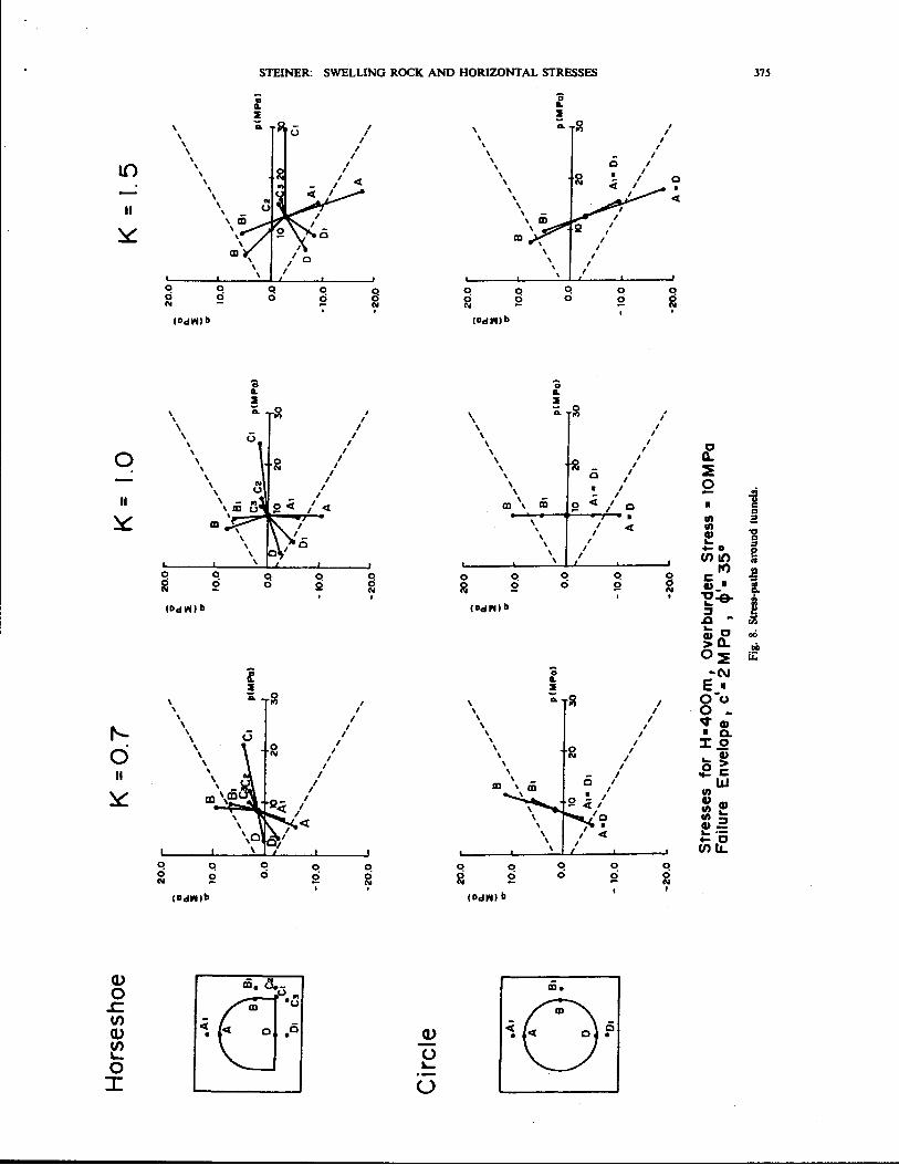
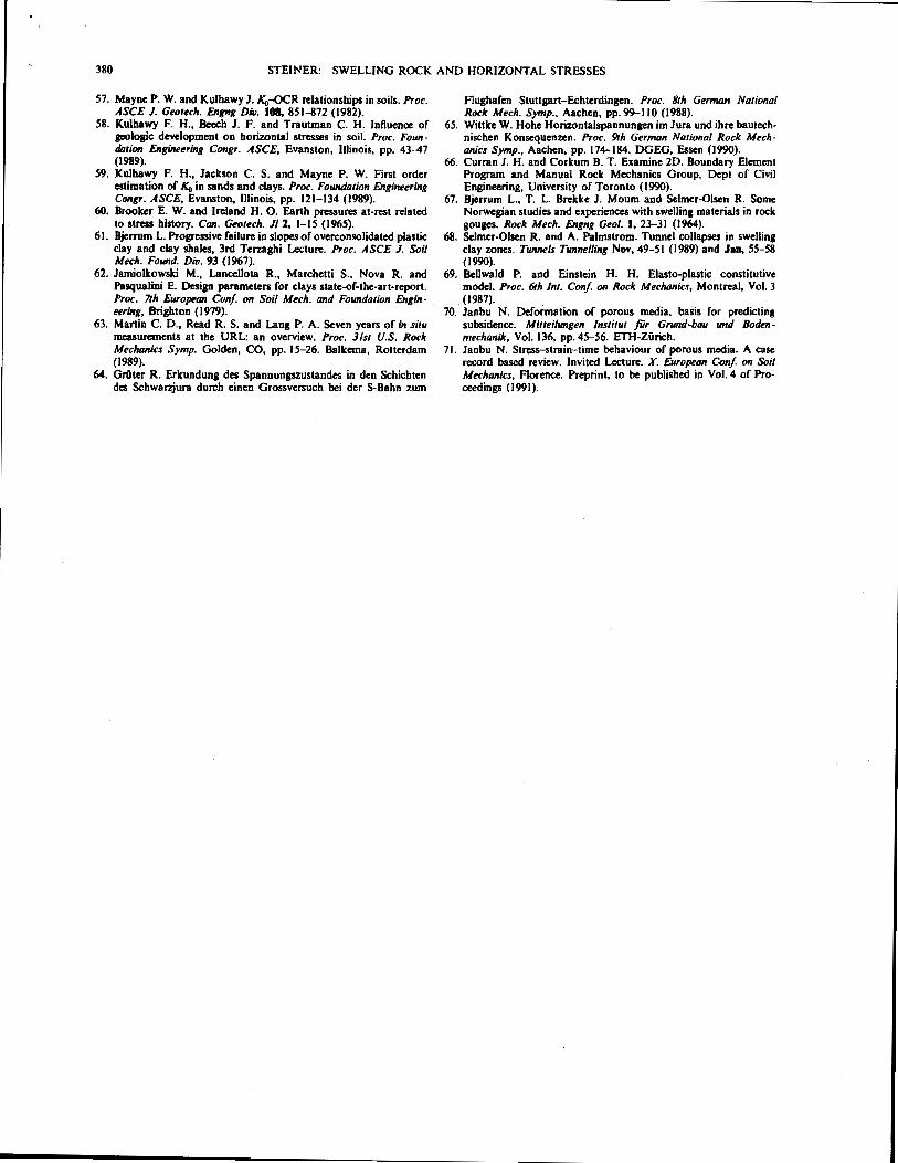
The stresses and stress-paths were obtained for a horseshoe and circular tunnel 400 m below ground and an overburden stress equal to 10 MPa. The horizontal stress ratio was varied from K0 = 0. 7 to hydrostatic (Ko = 1.0) to Ko = 1.5. The stresses for the horseshoe tunnel were obtained employing the boundary element program EXAMINE2D [66] and for the. circular tunnel with the analytical solution for a hole m a plate. The stress-paths based on elastic assumptions are shown in Fig. 8. . .
For the circular tunnel, stress-paths m the mvert are not much different from the springlines and the crown. For the case of hydrostatic initial stress (Ko = 1.0), the mean normal stress does not change and only shear stresses are created. At the springlines with a compressive stress-path, an increase of the stresses in the vertical direction results. In the invert and the crown an extensional stress-path is followed, i.e. the stresses in the vertical direction are decreased. For Ko < 1.0
Strain vs mean stress p Stresses in Oedometer
Heave
r Axial Strain
j Compression
Strain vs Deviator q
6 5
E~------A~x7io~I~S~tro~i~n----~
6
Unloading with water inflow -~+--- Loading (dryl
Stress Paths
Go- Gr q•--2-
GriA G u
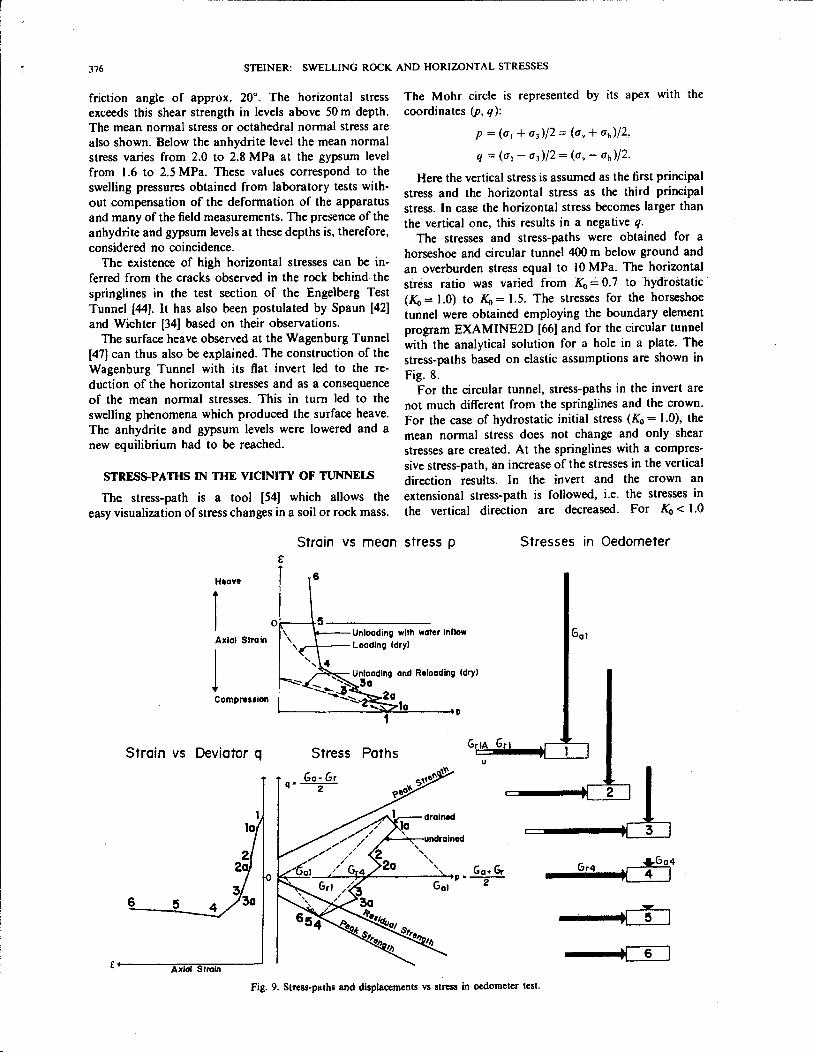
Fig. 9. Stress-paths and displacements vs stress in ocdometcr test.
'I ! 1 2
~I 3
Gr4 u +:Go4
4 I
::!E u 5
•( 6
STEINER: SWELLING ROCK AND HORIZONTAL STRESSES 377
IN-SITU LABORATORY Ca-.JSTRUCTIO'J
r1
" L J._ HffiiZONTALSTRESSES
LATERALSTRESSES
TANGENTIALSTRESSES
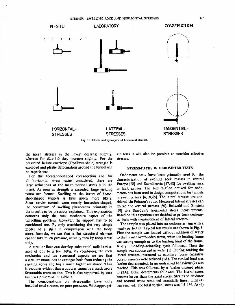
Fig. I 0. Effects and synonyms of horizontal stresses.
the mean stresses in the invert decrease slightly, whereas for Ko > 1.0 they increase slightly. For the presented failure envelope (Opalinus shale) strength is exceeded and plastic deformation around the tunnel will be experienced.
For the horseshoe-shaped cross-section and for all horizontal stress ratios considered, there are large reductions of the mean normal stress p in the invert. As soon as strength is exceeded, large yielding zones are formed. Swelling in the invert of horseshoe-shaped tunnels is thus much more likely. Since earlier tunnels were mostly horseshoe-shaped, the occurrence of swelling phenomena primarily in the invert can be plausibly explained. This explanation concerns only the rock mechanics aspect of the tunnelling problem. However, the support has to be considered too. By only considering the very simple model of a shell in compression with the hoop stress formula, we see that a fiat structural element cannot take much pressure, actually zero by hoop stress only.
A circular liner can develop substantial radial resistance of one to a few MPa. By combining the rock mechanics and the structural aspects we see that a circular tunnel has advantages both from reducing the swelling zones and has a much higher resistance. Thus it becomes evident that a circular tunnel is a much more favourable cross-section. This is also supported by case histories presented in Table 2.
The considerations on stress-paths have only included total stresses, no pore pressures. With appropri-
ate tests it will also be possible to consider effective stresses.
STRESS-PATHS IN OEDOMETER TESTS
Oedometer tests have been primarily used for the characterization of swelling rock masses in central Europe [28] and Scandinavia [67,68] for swelling rock in fault gauges. The 1-D relation derived for oedometers has been used in design computations for tunnels in swelling rock [4, 18, 65]. The lateral stresses are considered via Poisson's ratio. Measured lateral stresses can exceed the vertical stresses [60}. Bellwald and Einstein [69] cite Sun-Jon's horizontal stress measurements. Based on this experience we decided to perform oedometer tests with measurement of lateral stresses.
The sample was placed into an oedometer ring with a nearly perfect fit. Typical test results are shown in Fig. 8. First the sample was loaded without addition of water to the former overburden stress, when the loading frame was strong enough or to the loading limit of the frame. A dry unloading-reloading cycle followed. Then the sample was submerged in water (l ). During soaking the lateral stresses increased as capillary forces (negative pore pressures) were reduced (lA). The vertical load was further decremented. In an undrained behaviour (2) was reached. This was followed by a further drained phase to (2A). Other decrements followed. The lateral stress became larger than the axial stress. Strains vs deviator and normal stress remained essentially linear until (4) was reached. The total vertical stress was 0.5-1%. As (4)
378 STEINER: SWELLING ROCK AND HORIZONTAL STRESSES
the strains substantially increased with practically constant stresses, this must be a creep deformation. The stress state at (4) is close to the peak strength envelope. From (4) to (5) another 5% of strain was accumulated.
By considering the results shown in Fig. 8 one concludes that different combined phenomena happen in an oedometer test upon unloading. There is undrained stress redistribution. Then there is drained volume change, i.e. true swelling. Finally once the failure envelope is reached, yielding and creep deformations, probably undrained and drained creep combined, will occur.
Around a tunnel we first have undrained stress redistribution. The stress path from (I) to (4) is just one unloading step. There is no intermediate drainage (swelling) possible. Then plastic yielding occurs. A swelling law derived from oedometer tests considering only axial stresses and strains is barely able to consider all these phenomena properly. Furthermore, a stress path in an oedometer does not correspond to the behaviour at the springlines of a tunnel.
The oedometer test is, compared to the triaxial test, a relatively simple test to perform. Based on the above experience, as well as other recent applications of the oedometer to rock settlement problems [70, 71], improvements could be made to the testing procedures. We suggest the following:
I. Horizontal stresses should always be measured. 2. Pore pressures should be measured through the
bottom plate. 3. Loading and reloading should be automated. 4. At first a regular swelling pressure test should be
performed, with the recording of the development with time of the swelling pressure and the compensation of the deformation of the load frame.
5. The sample should be loaded above its in situ overburden stress, if possible the maximum past pressure should be determined.
6. Unloading should be in large steps from the in situ stress until the failure envelope is reached, i.e. just one undrained loading step.
From the foregoing discussion it is evident that effective stresses and pore pressures must be considered explicitly in the testing procedures and design computations.
CONCLUSIONS
Horizontal stresses play a major role in the behaviour of rock around underground openings, but particularly in swelling rock. Effects of horizontal stresses and their synonymous equivalents are shown in Fig. 10. Under original conditions, in situ we have horizontal stresses, in the laboratory lateral stresses are considered and around an artificial opening we consider tangential stresses. We have to consider the effect of stresses that are perpendicular to the direction of our direct interest.
Lateral stresses have to be measured or controlled in laboratory tests. Conventional oedometer tests do not sufficiently represent the behaviour of the ground around a tunnel. Stress-path triaxial tests with measure-
ment of the pore pressure response are necessary. Due to their simplicity, the use of improved oedometer tests can still be beneficial. From the knowledge of the maximum past pressure and todays overburden, the overconsolidation ratio can be computed and horizontal stress may be estimated with empirical relations.
For pure clay shales from Jura tunnels, in situ swelling pressures up to 0.3 MPa can be expected, with one exception, in Oxfordien the swelling pressures go up to 0.7 MPa. Stress redistribution must be permitted but not long-term yielding. Similar to soil mechanics, undrained and drained behaviour should be differentiated and pore pressures and their development should be explicitly considered.
Anhydritic shales heave different from regular shales. Not all the interaction phenomena between shale and anhydrite/gypsum are understood, but there is definitely an interaction between swelling of shale (physical) and the transformation of anhydrite into gypsum (chemical effects). In anhydritic shale swelling pressures of 2.5 MPa are most unlikely to be exceeded. The probable mean value based on the present experience are in the range of 1.6-2.0 MPa. The build-up of the swelling pressure or heave depends on the construction procedure and the cross-section. Circular cross-sections with rapid support placement of sufficient strength, i.e. fast ring closure are preferable. Yielding accompanied by a reduction of the mean normal stresses and water access must be avoided. When natural and redistributed normal stresses are kept locked-in in the rock mass, the pressures on the liner may be much less.
Laboratory tests on anhydritic shale show large scatter of the swelling pressures. This may be caused by mineralogical heterogenity or the influence of the testing procedures. Slippage along the interface may prevent the build-up of higher horizontal stresses. Lateral swelling stresses must be measured.
Construction procedure and cross-section of the underground opening are factors that significantly influence swelling behaviour in tunnels. Water should be kept away from swelling rock, falling tunnel drives must be avoided and circular cross-sections followed by a sufficiently strong liner are preferable.
Acknowledgements-Part of this study was developed for the design of the Wisenberg Tunnel of the Swiss Federal Railroads, SBB-CFF, General Directorate in Berne and the Directorate of District II in Lucerne. Permission granted for this publication is gratefully acknowledged. Further thanks go to the author's colleagues of the lngenieurgemeinschaft Wisenberg Tunnel, the joint·venture designing the tunnel.
Accepted for publication 22 February 1993.
REFERENCES
I. Wiesmann E. Der Bau des Hauenstein-Basis-TUIIllels. Memorial volume to the opening of the Hauenstein Base Tunnel, Kiiinrnedy & Frey, Bern (1917).
2. Etterlin A. (Ed.) Die Rekonstruktion des Haucnstein-Basistunnels, 1980-1986, Otten (1986).
3. Steiner W., Rossi P. P. and Devin P. Flatjack measurements in the lining of the Hauenstein tunnel as a design base for the· New Wisenberg tunnel. Proc. Int. Congr. on Tunneling, Toronto (1989)
STEINER: SWELLING ROCK AND HORIZONTAL STRESSES 379
4. Grob H. Schwelldruck im Belchentunnel. Int. Symp. on Underground Construction, Lucerne, pp. 99-119 (1972).
5. Einstein H. H. Tunneling in swelling rock. Unclergr. Space 4, 51...()1 (1979).
6. Steiner W. Wisenbergtunnel, Bahn 2000. Proc. Symp. Swiss National Group on Underground Construction (in German), pp. 69--80. Delemont, SIA-FGU, Zurich (1989).
1. Schillinger R. Adler Tunnel, Bahn 2000 Proc. Symp. Swiss National Group on Underground Construction (in German), pp. 81-88. Delemont, SIA-FGU, Zurich (1989).
8. Steiner W. and Metzger R. Experience from tunnels in swelling rock. Report to Swiss Federal Railways for the Wisenberg-Tunnel Project (in German) (1988).
9. Triimpy R. (Ed.) Geology of Switzerland: A Guidebook; Part A: An Outline of the Geology of Switzerland. Wepf, Basel (1980).
10. Pressel W. and Kaufmann J. Der Bau des Houensteintunnel:r auf der Schweizerischen Centra/hahn. Bahnmaier, Basel (1860).
II. Golta A. Rekonstruktion des Oberen Hauenstein-tunnels. Published Report to Swiss Federal Railroads (1974).
12. Kovari K., Amstad C. and Anagnostou G. Design/construction methods-tunneling in swelling rocks. Proc. 29th U.S. Rock Mechanics Symp., pp. 17-32 (1988).
13. Kovari K., Madsen F. T. and Amstad C. Tunneling with yielding support in swelling .rock. Proc. Int. Symp. on Weak Rock, Tokyo, pp. 1019-1026 (1981).
14. Egger P., Mathier J. F., Descoeudres F. and Kohler P. Einschrinkung des Baugrundrisikos durch Auffahren cines Probestollens, Beispiel Mont Terri Tunnel. Proc. Symp. on Safety and Risk in Underground Construction, Zurich, pp. 15-23 (1991).
15. Guerpillon Y. and Allagnat D. Les mesures geotechniques effectues lors de Ia construction du tunnel autoroutier de Chamoise. Proc. Int. Congr. on Large Underground Openings, Florence, Vol. I, pp. 471)..479 (1986).
16. Nguyen Minh D., Habib P. and Guerpillon Y. Time-dependent behaviour of a pilot tunnel driven in hard marls. Proc. JSRM Symp. Design and Performance of Underground Excavations, Cambridge, U.K., pp. 453-459.
17. Hingant P. Le creusement du tunnel de Chamoise. Proc. Int. Congr. on Large Underground Openings, Florence, Italy, Vol. I, pp. 480-488 (1986).
18. Einstein H. H., Bischoff N. and Hofmann E. Das Verhalten von Stollensohlen in quellendem Mergel. Proc. Int. Symp. on Underground Construction, Lucerne, pp. 296-319 (1972).
19. Einstein H. H. and BischoffN. Design of tunnels in swelling rock. Proc. 16th U.S. National Symp. on Rock Mechanics, Minneapolis, 1975, pp. 185-197. ASCE, New York (1977).
20. Schneider T. R. Seelisberg Tunnel, Geologischer Schlussbericht, Zusammenfassung. Beitriige zur Geologie der Schweiz. Geotechnische Serie, Lieferung 65, (1984).
21. Meyer E., Mandach F., Hasler M. and Kress H. Bau und Montagearbeiten. Schw. lng. Architekt 98, 1242-1251 (1980).
22. Skaanes S. Ausbruch und Sicherung in Valanginienmergel, Felsmechanische Aspekte. Schw. Jng. Architekt 98, 1265-1271 (1980).
23. Darla G., Pazzagli G., Rabagliati U. and Travalini S. The San Donato Tunnel (Florence). Proc. Int. Congr. on Tunneling, Firenze, Italy, Vol. I, pp. 61...()9 (1986).
24. Phelps D. J. and Brandt J. R. Performance of tunnels in swelling rock at Dickson Dam, Alberta. Canadian Tunneling, pp. 99-117. Bi-Tech, Vancouver (1989).
25. Sahores J. Contribution a l'etude des phenomenes mi:caniques accompagnant l'hydratation de !'anhydrite These de doctoral, Faculte des Sciences, Universite de Toulouse (1962).
26. Blount C. W. and Dickson F. W. Gypsum-anhydrite equilibria in the system CaSOcHP and CaS04-NaCI-H20. Am. Mineral. 58, 323-331 (1973).
27. Gassmann J. Gysel M. and Schneider J. F. Anhydrit als Wirtgestein fiir die Endlagerung radioaktiver Abfiille in der Schweiz. Technical Report Nagra NTBI2, Baden (1979).
28. Huder J. and Amberg G. Quellung in Merge!, Opalinus-ton und Anhydrit. Schweizer. Bauzeit. 83, 975-980 (1970).
29. Henke K. F., Kaiser W. and Nagel D. Geomechanische Untersuchungen im Gipskeuper Forschungsberichte iiber Durchfiihrung einesfelsmechanischen Grossversuches in tier Nordrohre des Wagenburgtunnels in Stullgart, Strassenbau und Strassenverkehrstechnik, Vol. 184, pp. 149-162 (!975).
30. Kirschke D. Laboratory and in situ swelling tests for the Freudenstein Tunnel. Proc. 6th Int. Conf. on Rock Mechanics, Montreal, Vol. 3, pp. 1492-1496 (!987).
31. Kirschke D. Neue Versuchstechniken und Erkenntnisse zum
RMMS 30/<-E
Anhydritschwellen. Abstract of Paper presented to X. German National Rock Mech. Symp., Aachen (1992).
32. Beiche H. Bemessung und Bau eines Tunnels in anhydrithaltigem Gebirge (B-14 Tunnel in Stullgart). Proc. 9th German NationtJI Rock Mech. Symp., Aachen, pp. 185-207. DGEG, Essen (1990).
33. Wichter L. Quellen anhydrithaltiger Tongesteine. Bautechnik, Berlin 66, I -6 (1989).
34. Wichter L. Horizontal stresses in anhydriceous rock. Proc. 7th Int. Congr. Rock Mech., Aachen, pp. 367-370 (1991).
35. Madsen F. T. and Niiesch R. Langzeitquellverhalten von Tongesteinen und tonigen Sulfatgesteinen. Mitteillmgen IGB-ETH Ziirich, Vol. 140 (1990).
36. Madsen F. T. and Niiesch R. The swelling behaviour of claysulfate rocks. Proc. 7th Int. Congr. on Rock Mech., Aachen, pp. 285-288 (1991).
37. Golla A. Schwellvorginge im Planum schweizerischer Bahntunnel. Rock Mechanics, Supplementum 5, Vienna, pp. 231-243 (1976).
38. Schillinger G. Die Felsdriicke im Gipskeuper des Belchentunnels. Strasse Verkehr, Ziirich 56 (1970).
39. Aegerter and Bosshardt. New measurements from the Belchen Tunnel. Report to Swiss Railroads (1988).
40. Werder F. Sanierungs- und Erneuerungsarbeiten im Belchentunnel N2. Proc. Symp. Swiss National Group on Underground ColtS/ruction (in German), pp. 53-58. Delemont, SIA-FGU, Zurich (1989).
41. Gysel M. Die Messung der Quelldeformationen der Anhydritgruppe im Gipsbergwerk Felsenau. Wasser, Energie, Luft, Baden, Switzerland 84, 101-110 {1992).
42. Spaun G. Ueber die Ursachen von Sohlhebungen im Gipskeuper. Proc. 2nd German National Symp. on Engineering Geology, DGEG, Essen (1979).
43. Kuhnkenn K. and Lorscheider W. Exploratory gallery with test enlargement hall for the Engelberg Base Tunnel of the HeilbronnStuttgart Motorway. Rock Mechanics, Supplementum 8, pp. 147-172.
44. Kuhnhenn K., Bruder J. and Lorscheider W. Sondierstollen und Probestrecken fiir den Engelberg-Basistunnel. Proc. 2nd German National Congr. on Engineering Geology. DGEG, Essen (1979).
45. Wittke W. and Pierau G. Fundamentals for the design and construction of tunnels in swelling rock. Proc. 41h Int. Congr. on Rock Mechanics, Montreux, Vol. 2, pp. 719-729 (1979).
46. Krause H. and Wurm F. Geologische Grundlagen und Untersuchungen zum Problem der Sohlhebungen in Keupertunneln Baden-Wiirttembergs. Forschungsberichte iiber Durchfiihrung einesfelsmechanischen Grossversuches in der Nordrohre des Wagenburgtunnels in Stullgart. Strassenbau und Strassenverkehrstechnik 184, 149-162 (1975).
47. Henke K. F., Kaiser W. and Beiche H. Verhalten von Tunnelbauwerken in quellfiihigen Schichten des Gipskeupers. Proc. 2nd German National Symp. on Engineering Geology, pp. 135-142. Fellbach DGEG, Essen (1979).
48. Wichter L. Ergebnisse von Langzeitmessungen im Wagenburgtunnel, Stuttgart. Tunnel No.4, pp. 254-257 (1985).
49. Paul A. and Wichter L. Das Langzeitverhalten von Tunnelbauwerken im quellenden Gebirge-Neuere Messergebnisse vom Stuttgarter Wagenburgtunnel. Paper presented to X. German National Rock Mech. Symp., Aachen (1992).
50. Prommersberger G. and Kuhnhenn K. The Freudenstein Tunnel: tunnel construction in swelling rock. Proc. RETC, Los Angeles, pp. 678-700. AIME, Littleton (1989).
51. Fecker E. Untersuchung von Schwellvorgingen und Erprobung von Auskleidungskonzepten in situ beim Freudensteintunnel. Paper presented to X. German National Rock Mech. Symp., Aachen (1992).
52. Fecker E. and App U. Erforschung des Schwelldruck problems im Anhydrit-Bisherige Ergebnisse des felsmechanischen Messprogramms im Freudensteintunnel der Deutschen Bundesbahn. Paper presented at Esslingen (1992).
53. Tedd P., Powell J. J., Charles J. A. and Uglow I. M. In situ measurements of earth pressures using push-in spade-shaped pressure cells-10 years' experience. Proc. Geotechnical Instrumentation in Practice, Purpose, Performance and Interpretation. Telford, London (1989).
54. Lambe T. W. and Whitman R. V. Soil Mechanics. Wiley, New York (1969).
55. Skempton A. W. Horizontal stresses in an over-consolidated eocene clay. Proc. 5th Int. Congr. on Soil Mechanics and Foundation Engineering, Paris, Vol. I, pp. 531-537 (1961).
56. Terzaghi K. Discussion of horizontal stresses in an over-consolidated eocene clay by A. W. Skempton. Proc. 5th Int. Con/. on Sot/ Mechanics and Foundation Engineering, Vol. 3, pp. 144-145 (1961).
380 STEINER: SWELLING ROCK AND HORIZONTAL STRESSES
57. Mayne P. W. and Kulhawy J. Ko-OCR relationships in soils. Proc. ASCE J. Geotech. Engng Div. 188. 851-872 (1982).
58. Kulhawy F. H., Beech J. F. and Trautman C. H. Influence of geologic d~lopment on horizontal stresses in soil. Proc. Foundation Engineering Congr. ASCE, Evanston, Illinois, pp. 43-47 (1989).
59. Kulhawy F. H., Jackson C. S. and Mayne P. W. First order estimation of Ko in sands and clays. Proc. FoundDtion Engineering Congr. ASCE, Evanston, Illinois, pp. 121-134 (1989).
60. Brooker E. W. and Ireland H. 0. Earth pressures at-rest related to stress history. Can. Geotech. J/l, 1-15 (1965).
61. Bjerrum L. Progressive failure in slopes of overconsolidated plastic clay and clay shales, 3rd Terzaghi Lecture. Proc. ASCE J. Soil Mech. Found. Div. 93 (1967).
62. Jamiolkowski M., Lancellota R., Marchetti S., Nova R. and Pasqualini E. Design parameters for clays state-of-the-art-report. Proc. 7th European Conf. on Soil Mech. and Foundation Engineering, Brighton (1979).
63. Martin C. D., Read R. S. and Lang P. A. Seven years of in situ measurements at the URL: an overview. Proc. Jist U.S. Rock Mechanics Symp. Golden, CO, pp. I S-26. Balkema, Rotterdam (1989).
64. Griiter R. Erkundung des Spannungszustandes in den Schichten des Schwarzjura durch einen Grossversuch bei der S-Bahn zum
Flughafen Stuttgart-Echterdingen. Proc. 8th Germ(J/1 National Rock Mech. Symp., Aachen, pp. 99-110 (1988).
65. Wittke W. Hohe Horizontalspannungen im Jura und ihre bautechnischen Konsequenzen. Proc. 9th German National Rock Mechanics Symp., Aachen, pp. 174-184. DGEG, Essen (1990).
66. Curran J. H. and Corkum B. T. Examine 2D. Boundary Element Program and Manual Rock Mechanics Group, Dept of Civil Engineering; University of Toronto (1990).
67. Bjerrum L., T. L. Brekke J. Mourn and Selmer-Olsen R. Some Norwegian studies and experiences with swelling materials in rock gouges. Rock Mech. Engng Geol. I, 23-31 (1964).
68. Selmer-Olsen R. and A. Palmstrom. Tunnel collapses in swelling clay zones. Tunnels Tunnelling No,., 49-51 (1989) and Jaa, 55-58 (1990).
69. Bellwald P. and Einstein H. H. Elasto-plastic constitutive model. Proc. 6th Int. Conf. on Rock Mechanics, Montreal, Vol. 3 (1987).
70. Janbu N. Deformation of porous media, basis for predicting subsidence. Milleilungen /nstitut fiir Grund-bau und Bodenmechanik, Vol. 136, pp. 45-56. ETH-Ziirich.
71. Janbu N. Stress-strain-time behaviour of porous media. A case record based review. Invited Lecture. X. European Conf. on Soil Mechanics, Florence. Preprint, to be published in Vol. 4 of Proceedings (1991).


![Moselele Book6 Extraction · [Em][G*]!Iwannarock![Am*]!(ROCK)!rock![Am*]!(ROCK)!rock![Am]!(ROCK)! [Em][G*]!Iwannarock![Am*]!(ROCK)!rock![Am*]!(ROCK)!rock![Am]!(ROCK)! I[Em]!want[C*]!to!rock