SVF FS7 IOM
5
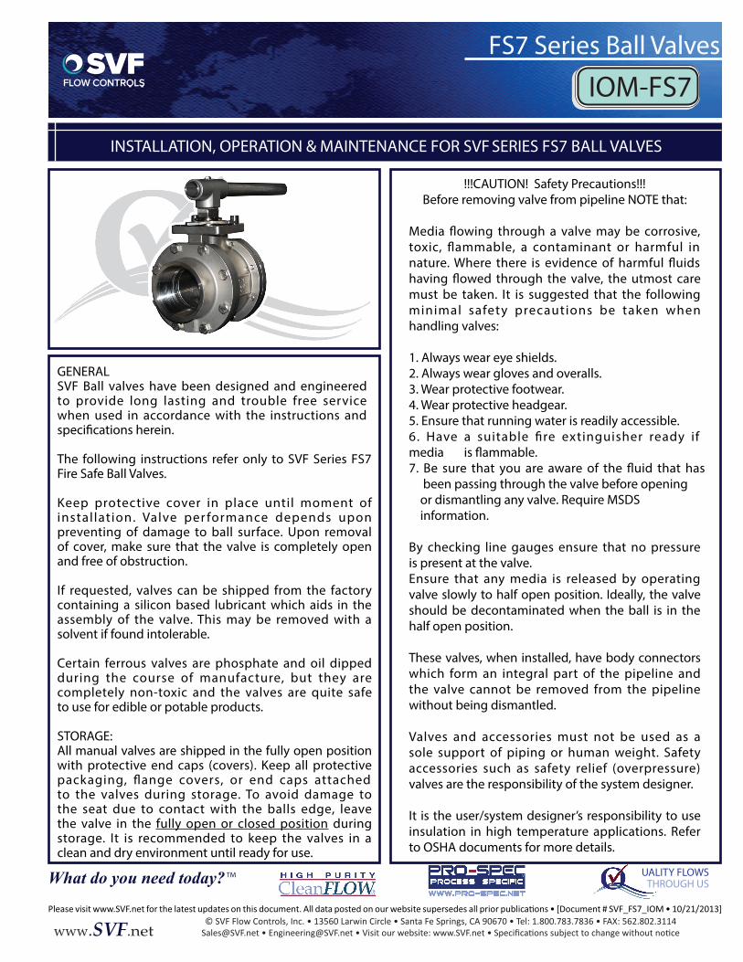
© SVF Flow Controls, Inc. • 13560 Larwin Circle • Santa Fe Springs, CA 90670 • Tel: 1.800.783.7836 • FAX: 562.802.3114 www.SVF.net INSTALLATION, OPERATION & MAINTENANCE FOR SVF SERIES FS7 BALL VALVES FS7 Series Ball Valves IOM-FS7 UALITY FLOWS THROUGH US What do you need today? TM GENERAL SVF Ball valves have been designed and engineered to provide long lasting and trouble free service when used in accordance with the instructions and The following instructions refer only to SVF Series FS7 Fire Safe Ball Valves. Keep protective cover in place until moment of installation. Valve performance depends upon preventing of damage to ball surface. Upon removal of cover, make sure that the valve is completely open and free of obstruction. If requested, valves can be shipped from the factory containing a silicon based lubricant which aids in the assembly of the valve. This may be removed with a solvent if found intolerable. Certain ferrous valves are phosphate and oil dipped during the course of manufacture, but they are completely non-toxic and the valves are quite safe to use for edible or potable products. STORAGE: All manual valves are shipped in the fully open position with protective end caps (covers). Keep all protective packaging, flange covers, or end caps attached to the valves during storage. To avoid damage to the seat due to contact with the balls edge, leave the valve in the fully open or closed position during storage. It is recommended to keep the valves in a clean and dry environment until ready for use. !!!CAUTION! Safety Precautions!!! Before removing valve from pipeline NOTE that: Media flowing through a valve may be corrosive, toxic, flammable, a contaminant or harmful in nature. Where there is evidence of harmful fluids must be taken. It is suggested that the following minimal safety precautions be taken when handling valves: 1. Always wear eye shields. 2. Always wear gloves and overalls. 3. Wear protective footwear. 4. Wear protective headgear. 5. Ensure that running water is readily accessible. 6. Have a suitable fire extinguisher ready if media 7. Be sure that you are aware of the fluid that has been passing through the valve before opening or dismantling any valve. Require MSDS information. By checking line gauges ensure that no pressure is present at the valve. Ensure that any media is released by operating valve slowly to half open position. Ideally, the valve should be decontaminated when the ball is in the half open position. These valves, when installed, have body connectors which form an integral part of the pipeline and the valve cannot be removed from the pipeline without being dismantled. Valves and accessories must not be used as a sole support of piping or human weight. Safety accessories such as safety relief (overpressure) valves are the responsibility of the system designer. It is the user/system designer’s responsibility to use insulation in high temperature applications. Refer to OSHA documents for more details.
Transcript of SVF FS7 IOM
© SVF Flow Controls, Inc. • 13560 Larwin Circle • Santa Fe Springs, CA 90670 • Tel: 1.800.783.7836 • FAX: 562.802.3114www.SVF.net
INSTALLATION, OPERATION & MAINTENANCE FOR SVF SERIES FS7 BALL VALVES
FS7 Series Ball Valves
IOM-FS7
UALITY FLOWSTHROUGH USWhat do you need today? TM
GENERALSVF Ball valves have been designed and engineered to provide long lasting and trouble free service when used in accordance with the instructions and
The following instructions refer only to SVF Series FS7 Fire Safe Ball Valves.
Keep protective cover in place until moment of instal lation. Valve per formance depends upon preventing of damage to ball surface. Upon removal of cover, make sure that the valve is completely open and free of obstruction.
If requested, valves can be shipped from the factory containing a silicon based lubricant which aids in the assembly of the valve. This may be removed with a solvent if found intolerable.
Certain ferrous valves are phosphate and oil dipped during the course of manufacture, but they are completely non-toxic and the valves are quite safe to use for edible or potable products.
STORAGE:All manual valves are shipped in the fully open position with protective end caps (covers). Keep all protective packaging, �ange covers, or end caps attached to the valves during storage. To avoid damage to the seat due to contact with the balls edge, leave the valve in the fully open or closed position during storage. It is recommended to keep the valves in a clean and dry environment until ready for use.
!!!CAUTION! Safety Precautions!!!Before removing valve from pipeline NOTE that:
Media �owing through a valve may be corrosive, toxic, �ammable, a contaminant or harmful in nature. Where there is evidence of harmful �uids
must be taken. It is suggested that the following minimal safety precautions be taken when handling valves:
1. Always wear eye shields.2. Always wear gloves and overalls.3. Wear protective footwear.4. Wear protective headgear.5. Ensure that running water is readily accessible.6. Have a suitable �re extinguisher ready if media 7. Be sure that you are aware of the �uid that has been passing through the valve before opening or dismantling any valve. Require MSDS information.
By checking line gauges ensure that no pressure is present at the valve.Ensure that any media is released by operating valve slowly to half open position. Ideally, the valve should be decontaminated when the ball is in the half open position.
These valves, when installed, have body connectors which form an integral part of the pipeline and the valve cannot be removed from the pipeline without being dismantled.
Valves and accessories must not be used as a sole support of piping or human weight. Safety accessories such as safety relief (overpressure) valves are the responsibility of the system designer.
It is the user/system designer’s responsibility to use insulation in high temperature applications. Refer to OSHA documents for more details.
© SVF Flow Controls, Inc. • 13560 Larwin Circle • Santa Fe Springs, CA 90670 • Tel: 1.800.783.7836 • FAX: 562.802.3114www.SVF.net
INSTALLATION, OPERATION & MAINTENANCE FOR SVF SERIES FS7 BALL VALVES
FS7 Series Ball Valves
IOM-FS7
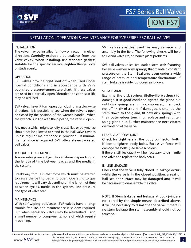
INSTALLATION
direction. Carefully exclude pipe sealants from the valve cavity. When installing, use standard gaskets suitable for the speci�c service. Tighten �ange bolts or studs evenly.
OPERATIONSVF valves provide tight shut o� when used under normal conditions and in accordance with SVF’s published pressure/temperature chart. If these valves are used in a partially open (throttled) position seat life may be reduced.
SVF valves have ¼ turn operation closing in a clockwise direction. It is possible to see when the valve is open or closed by the position of the wrench handle. When the wrench is in line with the pipeline, the valve is open.
Any media which might solidify, crystallize or polymerize should not be allowed to stand in the ball valve cavities unless regular maintenance is provided. If minimal maintenance is required, SVF o�ers steam jacketed ball valves.
TORQUE REQUIREMENTSTorque ratings are subject to variations depending on the length of time between cycles and the media in the system.
Breakaway torque is that force which must be exerted to cause the ball to begin to open. Operating torque requirements will vary depending on the length of time between cycles, media in the system, line pressure and type of valve seat.
MAINTENANCEWith self-wiping ball/seats, SVF valves have a long, trouble free life, and maintenance is seldom required. But, when necessary, valves may be refurbished, using a small number of components, none of which require machining.
SVF valves are designed for easy service and
to extend valve life, or reduce plant problems.
SVF ball valves utilize live-loaded stem seals featuring Belleville washers (disk springs) that maintain constant pressure on the Stem Seal area even under a wide range of pressure and temperature �uctuations. If stem leakage is evident proceed as follows:
STEM LEAKAGEExamine the disk springs (Belleville washers) for damage. If in good condition tighten the gland nut until disk springs are �rmly compressed, then back nut o� 1/16th of a turn. If damaged, dismantle the stem down to the gland, �t new disk springs with their outer edges touching, replace and retighten using gland nut. Further maintenance necessitates dismantling of the valve.
LEAKAGE AT BODY JOINTCheck for tightness at the body connector bolts. If loose, tighten body bolts. Excessive force will damage the bolts. (See Table A below)If there is still leakage it will be necessary to dismantle the valve and replace the body seals.
IN-LINE LEAKAGECheck that the valve is fully closed. If leakage occurs while the valve is in the closed position, a seat or ball sealant surface may be damaged and it will be necessary to disassemble the valve.
NOTE: If Stem leakage and leakage at body joint are not cured by the simple means described above, it will be necessary to dismantle the valve. If there is no stem leakage the stem assembly should not be touched.
2
© SVF Flow Controls, Inc. • 13560 Larwin Circle • Santa Fe Springs, CA 90670 • Tel: 1.800.783.7836 • FAX: 562.802.3114www.SVF.net
INSTALLATION, OPERATION & MAINTENANCE FOR SVF SERIES FS7 BALL VALVES
FS7 Series Ball Valves
IOM-FS7
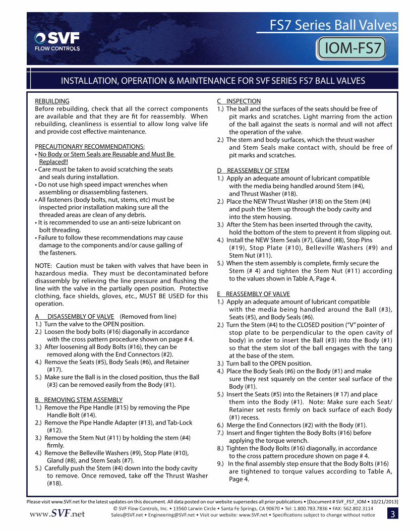
REBUILDINGBefore rebuilding, check that all the correct components are available and that they are �t for reassembly. When rebuilding, cleanliness is essential to allow long valve life
PRECAUTIONARY RECOMMENDATIONS: • No Body or Stem Seals are Reusable and Must Be Replaced!!• Care must be taken to avoid scratching the seats and seals during installation.• Do not use high speed impact wrenches when assembling or disassembling fasteners.• All fasteners (body bolts, nut, stems, etc) must be inspected prior installation making sure all the threaded areas are clean of any debris.• It is recommended to use an anti-seize lubricant on bolt threading.• Failure to follow these recommendations may cause damage to the components and/or cause galling of the fasteners.
NOTE: Caution must be taken with valves that have been in hazardous media. They must be decontaminated before
line with the valve in the partially open position. Protective clothing, face shields, gloves, etc., MUST BE USED for this operation. A DISASSEMBLY OF VALVE (Removed from line)1.) Turn the valve to the OPEN position.2.) Loosen the body bolts (#16) diagonally in accordance
with the cross pattern procedure shown on page # 4.3.) After loosening all Body Bolts (#16), they can be
removed along with the End Connectors (#2).4.) Remove the Seats (#5), Body Seals (#6), and Retainer
(#17).5.) Make sure the Ball is in the closed position, thus the Ball
(#3) can be removed easily from the Body (#1).
B. REMOVING STEM ASSEMBLY1.) Remove the Pipe Handle (#15) by removing the Pipe
Handle Bolt (#14).2.) Remove the Pipe Handle Adapter (#13), and Tab-Lock
(#12).3.) Remove the Stem Nut (#11) by holding the stem (#4)
4.) Remove the Belleville Washers (#9), Stop Plate (#10), Gland (#8), and Stem Seals (#7).
5.) Carefully push the Stem (#4) down into the body cavity to remove. Once removed, take o� the Thrust Washer (#18).
C INSPECTION1.) The ball and the surfaces of the seats should be free of
pit marks and scratches. Light marring from the action
the operation of the valve.2.) The stem and body surfaces, which the thrust washer
and Stem Seals make contact with, should be free of pit marks and scratches.
D REASSEMBLY OF STEM1.) Apply an adequate amount of lubricant compatible
with the media being handled around Stem (#4), and Thrust Washer (#18).
2.) Place the NEW Thrust Washer (#18) on the Stem (#4) and push the Stem up through the body cavity and into the stem housing.
3.) After the Stem has been inserted through the cavity, hold the bottom of the stem to prevent it from slipping out.
4.) Install the NEW Stem Seals (#7), Gland (#8), Stop Pins (#19), Stop Plate (#10), Belleville Washers (#9) and Stem Nut (#11).
Stem (# 4) and tighten the Stem Nut (#11) according to the values shown in Table A, Page 4.
E REASSEMBLY OF VALVE1.) Apply an adequate amount of lubricant compatible
with the media being handled around the Ball (#3), Seats (#5), and Body Seals (#6).
2.) Turn the Stem (#4) to the CLOSED position (“V” pointer of stop plate to be perpendicular to the open cavity of body) in order to insert the Ball (#3) into the Body (#1) so that the stem slot of the ball engages with the tang at the base of the stem.
3.) Turn ball to the OPEN position.4.) Place the Body Seals (#6) on the Body (#1) and make
sure they rest squarely on the center seal surface of the Body (#1).
5.) Insert the Seats (#5) into the Retainers (# 17) and place them into the Body (#1). Note: Make sure each Seat/Retainer set rests �rmly on back surface of each Body (#1) recess.
6.) Merge the End Connectors (#2) with the Body (#1).7.)
applying the torque wrench.8.) Tighten the Body Bolts (#16) diagonally, in accordance
to the cross pattern procedure shown on page # 4.9.)
are tightened to torque values according to Table A, Page 4.
3
© SVF Flow Controls, Inc. • 13560 Larwin Circle • Santa Fe Springs, CA 90670 • Tel: 1.800.783.7836 • FAX: 562.802.3114www.SVF.net
INSTALLATION, OPERATION & MAINTENANCE FOR SVF SERIES FS7 BALL VALVES
FS7 Series Ball Valves
IOM-FS7
in-lbs)
REPAIR KITSRepair Kits are available from SVF Flow Controls, Inc. Table B below shows what the kits consist of. When ordering a Repair Kit, please be sure to specify the type, size and seating material of the valve.
When repairing a valve use only SVF Flow Controls, Inc. authorized spare parts including; bolts and nuts, etc. In addition to maintenance kits, spare parts are available from SVF Flow Controls, Inc. They are: balls, stems and glands. If additional parts are required (body and ends) it is normally recommended that the complete valve be replaced.
not be used with the repair of any other valve. If the valve is altered in any way, no liability can be accepted by SVF Flow Controls, Inc.
TABLE B: GENERAL REPAIR KIT
4
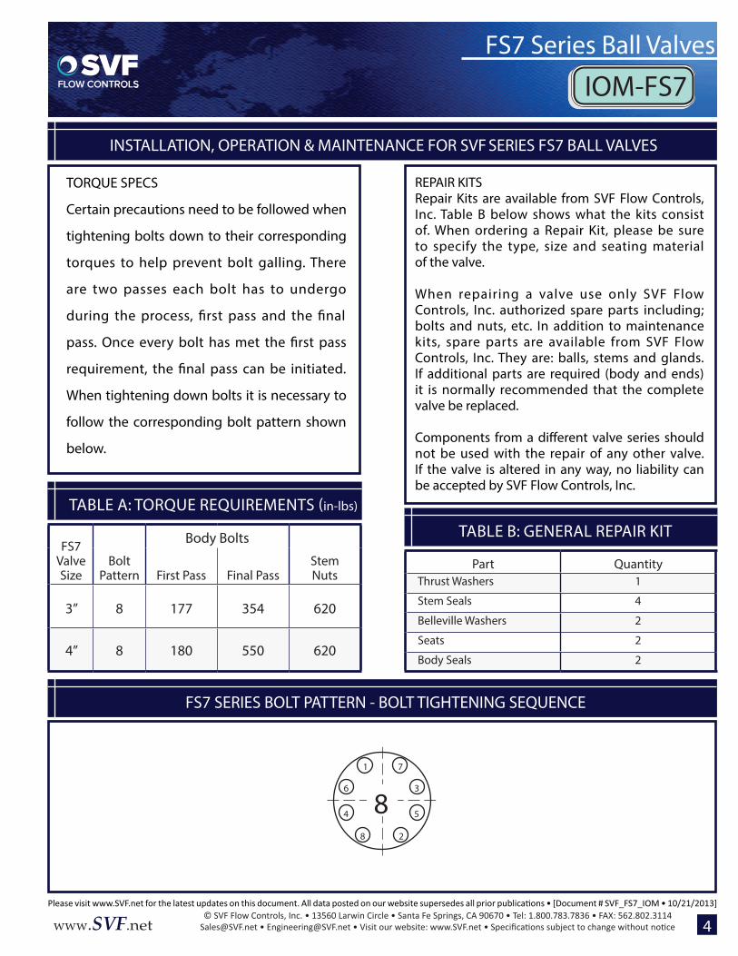
TORQUE SPECS
Certain precautions need to be followed when
tightening bolts down to their corresponding
torques to help prevent bolt galling. There
are two passes each bolt has to undergo
during the process, �rst pass and the �nal
requirement, the �nal pass can be initiated.
When tightening down bolts it is necessary to
follow the corresponding bolt pattern shown
below.
FS7 SERIES BOLT PATTERN - BOLT TIGHTENING SEQUENCE
1 7
8 2
4 5
6 3
8
FS7 Valve Size
Body Bolts
Bolt Pattern First Pass Final Pass
Stem Nuts
3” 8 177 354 620
4” 8 180 550 620
Part QuantityThrust Washers 1
Stem Seals 4
Belleville Washers 2
Seats 2
Body Seals 2
© SVF Flow Controls, Inc. • 13560 Larwin Circle • Santa Fe Springs, CA 90670 • Tel: 1.800.783.7836 • FAX: 562.802.3114www.SVF.net
INSTALLATION, OPERATION & MAINTENANCE FOR SVF SERIES FS7 BALL VALVES
FS7 Series Ball Valves
IOM-FS7
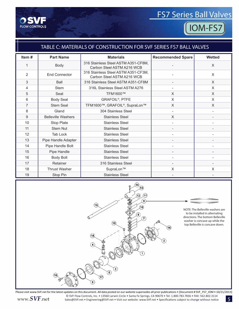
TABLE C: MATERIALS OF CONSTRUCTION FOR SVF SERIES FS7 BALL VALVES
5
Item # Part Name Materials Recommended Spare Wetted
1 Body 316 Stainless Steel ASTM A351-CF8M, Carbon Steel ASTM A216 WCB - X
2 End Connector 316 Stainless Steel ASTM A351-CF3M, Carbon Steel ASTM A216 WCB - X
3 Ball 316 Stainless Steel ASTM A351-CF8M - X4 Stem 316L Stainless Steel ASTM A276 - X5 Seat TFM1600™ X X6 Body Seal GRAFOIL®, PTFE X X7 Stem Seal TFM1600™, GRAFOIL®, SupraLon™ X X8 Gland 304 Stainless Steel - -9 Belleville Washers Stainless Steel X -10 Stop Plate Stainless Steel - -11 Stem Nut Stainless Steel - -12 Tab Lock Stainless Steel - -13 Pipe Handle Adapter Stainless Steel - -14 Pipe Handle Bolt Stainless Steel - -15 Pipe Handle Stainless Steel - -16 Body Bolt Stainless Steel - -17 Retainer 316 Stainless Steel - -18 Thrust Washer SupraLon™ X X19 Stop Pin Stainless Steel - -
NOTE: The Belleville washers are to be installed in alternating
directions. The bottom Belleville washer is concave up while the top Belleville is concave down.