SUZUKI GSXR 2000-2001-2002 PLUG AND PLAY KIT · Installation document: MyChron 3 Plus/Gold plug and...
16
Installation document: MyChron 3 Plus/Gold plug and play kit - Suzuki GSX-R 2000-2001-2002– Vers. 1.04 1 INSTALLATION DOCUMENTATION 27/05/2004 BIKE KIT Installation procedure for Suzuki GSX-R- 2000-2001-2002 kit Version 1.04 Suzuki GSX R 2000-2001-2002 600 – 750 – 1000cc SUZUKI GSXR 2000-2001-2002 PLUG AND PLAY KIT KIT DESCRIPTION The kit for Suzuki GSX-R is composed of the following objects: • MyChron 3 PLUS or MyChron 3 GOLD • Plug and play wiring for MyChron 3 PLUS or MyChron 3 GOLD • Installation kit including: 1 bracket, 2 anchor plugs, 4 anti-vibration mountings, screws, washers • TPS (Throttle Position Sensor) “split cable” (optional – available for GOLD versions only) • Gyroscope (optional – available for GOLD versions only) needed to map tracks • CD-ROM including Race Studio 2 software • Documentation The kit for Suzuki GSX-R has been developed for the K2 version and for the following cubic capacities: 600 cc, 750 cc, 1000 cc. Please, refer to the following table in order to understand which Suzuki GSX-R is supported by our kit. Cubic capacity (cc) Year 2000 Year 2001 Year 2002 600 √ √ √ 750 √ √ √ 1000 • √ √ √ = supported • = NOT supported The MyChron 3 Plus/Gold version Suzuki GSX-R has been designed and developed in order to be a “plug and play” system to be connected to the “on-board” wiring. The aim of this kit is to merge the functionalities of the stock dash together with the ones of a professional data acquisition system. The MyChron 3 Plus/Gold version Suzuki GSX-R may be used both on track (lap times, split times, engine’s parameters, gyroscope to map tracks) and on street (odometer, water temperature, oil pressure alarm, fuel level).
Transcript of SUZUKI GSXR 2000-2001-2002 PLUG AND PLAY KIT · Installation document: MyChron 3 Plus/Gold plug and...
Installation document: MyChron 3 Plus/Gold plug and play kit - Suzuki GSX-R 2
INSTALLATION DOCUMENTATION 27/05/2004 BIKE KIT
Installation procedure for Suzuki GSX-R- 2000-2001-2002 kit Version 1.04
Suzuki GSX R 2000-2001-2002
600 – 750 – 1000cc
SUZUKI GSXR 2000-2001-2002 PLUG AND PLAY KIT KIT DESCRIPTION The kit for Suzuki GSX-R is composed of the following objects:
• MyChron 3 PLUS or MyChron 3 GOLD • Plug and play wiring for MyChron 3 PLUS or MyChron 3 G• Installation kit including: 1 bracket, 2 anchor plugs, 4 anti-vi
washers • TPS (Throttle Position Sensor) “split cable” (optional – av
only) • Gyroscope (optional – available for GOLD versions only) ne• CD-ROM including Race Studio 2 software • Documentation
The kit for Suzuki GSX-R has been developed for the K2 versioncapacities: 600 cc, 750 cc, 1000 cc. Please, refer to the following twhich Suzuki GSX-R is supported by our kit.
Cubic capacity (cc)
Year 2000 Year 2001
600
√ √
750
√ √
1000
• √
√ = supported • = NOT supported The MyChron 3 Plus/Gold version Suzuki GSX-R has been dorder to be a “plug and play” system to be connected to the “on-boThe aim of this kit is to merge the functionalities of the stock dash professional data acquisition system. The MyChron 3 Plus/Gold version Suzuki GSX-R may be usedsplit times, engine’s parameters, gyroscope to map tracks) and temperature, oil pressure alarm, fuel level).
000-2001-2002– Vers. 1.04 1
OLD bration mountings, screws,
ailable for GOLD versions
eded to map tracks
and for the following cubic able in order to understand
Year 2002
√
√
√
esigned and developed in ard” wiring. together with the ones of a
both on track (lap times, on street (odometer, water
Installation document: MyChron 3 Plus/Gold plug and play kit - Suzuki GSX-R 2000-2001-2002– Vers. 1.04 2
The gauge, as the stock dash, is powered by the bike’s master switch. Moreover, when installing your MyChron 3, you do not have to cut, to bend or to drill anything: each component of the kit has been designed to be plug and play. The gauge has to be connected to the head lights using the bracket and the anchor plugs supplied with the system. Both bracket and anchor plugs are made in black anodized aluminum, in order to be lightweight and mechanically resistant. GENERAL NOTES – Read this before installing the system
• Do not cut any wiring: the wiring supplied with the kit is plug and play; • Please, be careful not to damage the on-board connectors when plugging/unplugging
them. In the following pages is described how to correctly manage them; • Do not install the system when the engine is hot. The on-board connectors are quite
near to the engine and you can burn yourself; • The space under the gas tank is quite confined: be careful not to hurt yourself when
plugging and unplugging the connectors. If necessary, please remove the gas tank in order to have a wider available space;
• Be careful not to loose stock screws and washers. • Do not damage the fairing when installing/uninstalling it.
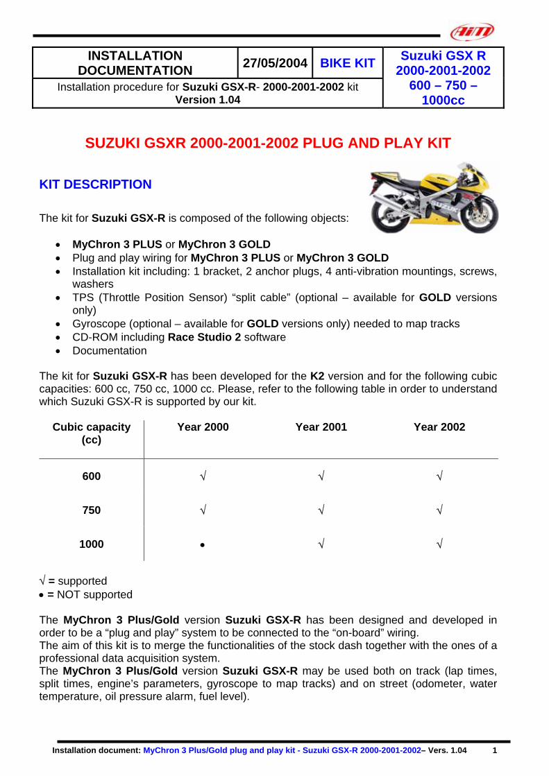
INSTALLATION STEP # 1 – Removing the front and lateral fairing The first installation step consists in removing the front transparent fairing and the right lateral fairing. It is suggested to remove the front fairing in order to uninstall the stock dash and install the new one in an easier way. The front fairing is locked to the chassis using 6 hex screws. In Figure 1 it is shown the location of four 4 mm hex screws: please remove them.
Figure 1: Front fairing – 4 mm hex screws

Installation document: MyChron 3 Plus/Gold plug and play kit - Suzuki GSX-R 2000-2001-2002– Vers. 1.04 3
In Figure 2 is shown the location of two 5 mm hex screws (one per each bike’s side). Once unscrewed them, you may remove the front transparent fairing. NOTE: the front fairing is installed using 4 anti-vibration mountings. When re-installing the front fairing, please be careful to install the anti-vibration mountings correctly.
Figure 2: Front fairing – 5 mm hex screw
The gauge’s wiring has to be installed on the right side of the bike. For this reason, removing bike’s right lateral fairing is necessary (left lateral fairing is not needed to be removed). The lateral fairing is fixed to the chassis with 10 hex screws and 4 plastic pins. The screws are red circled in Figure 3, while the plastic pins are highlighted with a red/ yellow arrow in Figure 3 and Figure 4. In particular, the plastic pin shown in Figure 3 is located close to the front splash-guard and to the front fork; this pin is visible only if front looking the bike.
Figure 3: Right lateral fairing – of screws/pins location
The other 3 plastic pins are located in the lower part of the bike. In order to correctly removing them, please see Figure 5.
Figure 4: Junction right-left fairing – pins location
Installation document: MyChron 3 Plus/Gold plug and play kit - Suzuki GSX-R 2000-2001-2002– Vers. 1.04 4
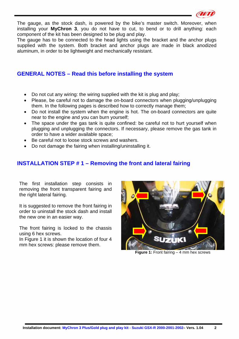
Please, use a flat screwdriver to remove the plastic pins. To remove the pin, insert the screwdriver inside the rectangular slot and rotate it. Once all hex screws and pins have been removed, you may uninstall the right lateral fairing.
Figure 5: Removing plastic pin using a flat screw driver
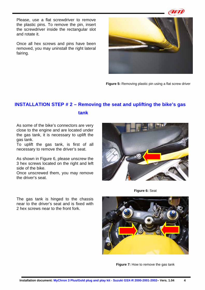
INSTALLATION STEP # 2 – Removing the seat and uplifting the bike’s gas
tank As some of the bike’s connectors are very close to the engine and are located under the gas tank, it is necessary to uplift the gas tank. To uplift the gas tank, is first of all necessary to remove the driver’s seat. As shown in Figure 6, please unscrew the 3 hex screws located on the right and left side of the bike. Once unscrewed them, you may remove the driver’s seat.
Figure 6: Seat
The gas tank is hinged to the chassis near to the driver’s seat and is fixed with 2 hex screws near to the front fork.
Figure 7: How to remove the gas tank
Installation document: MyChron 3 Plus/Gold plug and play kit - Suzuki GSX-R 2000-2001-2002– Vers. 1.04 5
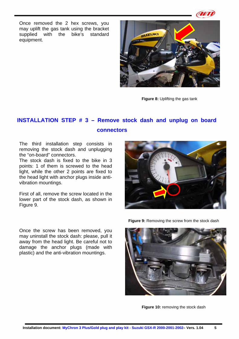
Once removed the 2 hex screws, you may uplift the gas tank using the bracket supplied with the bike’s standard equipment.
Figure 8: Uplifting the gas tank
INSTALLATION STEP # 3 – Remove stock dash and unplug on board
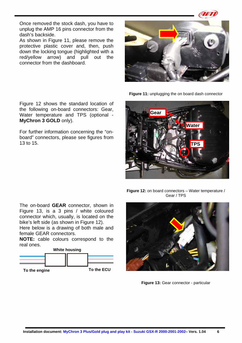
connectors The third installation step consists in removing the stock dash and unplugging the “on-board” connectors. The stock dash is fixed to the bike in 3 points: 1 of them is screwed to the head light, while the other 2 points are fixed to the head light with anchor plugs inside anti-vibration mountings. First of all, remove the screw located in the lower part of the stock dash, as shown in Figure 9.
Figure 9: Removing the screw from the stock dash
Once the screw has been removed, you may uninstall the stock dash: please, pull it away from the head light. Be careful not to damage the anchor plugs (made with plastic) and the anti-vibration mountings.
Figure 10: removing the stock dash
Installation document: MyChron 3 Pl
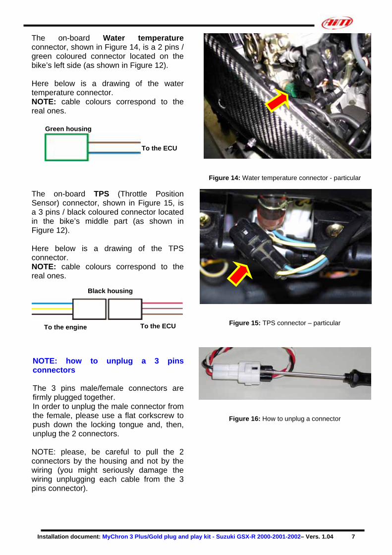
Once removed the stock dash, you have to unplug the AMP 16 pins connector from the dash’s backside. As shown in Figure 11, please remove the protective plastic cover and, then, push down the locking tongue (highlighted with a red/yellow arrow) and pull out the connector from the dashboard.
Figure 11: unplugging the on board dash connector
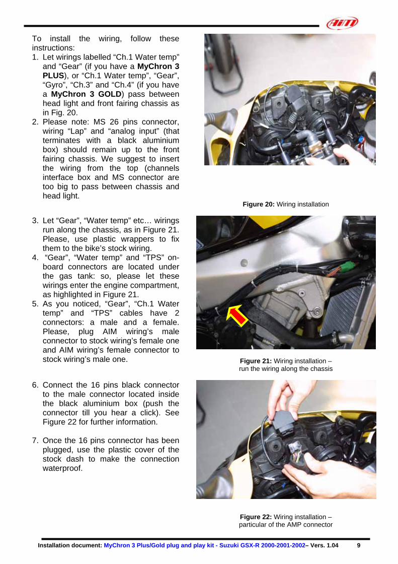
Figure 12 shows the standard location of the following on-board connectors: Gear, Water temperature and TPS (optional - MyChron 3 GOLD only). For further information concerning the “on-board” connectors, please see figures from 13 to 15.
Figure 12: on board connectors – Water temperature / Gear / TPS
The on-board GEAR connector, shown in
Figure 13, is a 3 pins / white coloured connector which, usually, is located on the bike’s left side (as shown in Figure 12). Here below is a drawing of both male and female GEAR connectors. NOTE: cable colours correspond to the real ones.
Water
Gear
TPS
White housing
To the engine
To the ECUus/Gold plug and play kit - Suzuki GSX-R 2000-2001-2002– Vers. 1.04 6
Figure 13: Gear connector - particular
Installation document: MyChron 3 P
The on-board Water temperature connector, shown in Figure 14, is a 2 pins / green coloured connector located on the bike’s left side (as shown in Figure 12). Here below is a drawing of the water temperature connector. NOTE: cable colours correspond to the real ones.
Figure 14: Water temperature connector - particular
The on-board TPS (Throttle Position Sensor) connector, shown in Figure 15, is a 3 pins / black coloured connector located in the bike’s middle part (as shown in Figure 12). Here below is a drawing of the TPS connector. NOTE: cable colours correspond to the real ones.
Figure 15: TPS connector – particular
NOTE: how to unplug connectors The 3 pins male/female cofirmly plugged together. In order to unplug the male cothe female, please use a flat push down the locking tonguunplug the 2 connectors. NOTE: please, be careful tconnectors by the housing anwiring (you might seriously wiring unplugging each cablepins connector).
To the ECU
Green housing
Black housing
To the engine
To the ECU
lus/Gold plug and play kit - Suzuki GSX-R 2000-2001-2002– Vers. 1.04 7
a 3 pins
nnectors are
nnector from corkscrew to e and, then,
o pull the 2 d not by the damage the from the 3
Figure 16: How to unplug a connector

Installation document: MyChron 3 Plus/Gold plug and play kit - Suzuki GSX-R 2000-2001-2002– Vers. 1.04 8
INSTALLATION STEP # 4 – Assembling the kit The fourth installation step consists in assembling the kit for Suzuki GSX-R. 1. Install the 4 anti-vibration mountings on
the backside of your MyChron 3 Plus/Gold;
2. Install the 2 anchor plugs on the aluminium bracket. Please use the Grover washers. See Figure 17 for further information.
3. Install your MyChron 3 Plus/Gold on the aluminium bracket: the bracket has to be fixed to your MyChron 3 in correspondence of the 4 anti-vibration mounting and has to be fixed using 4 screws and 4 Grover washers.
Figure 17: Anchor plugs installation - particular
In Figure 18 is shown the correct assembly of MyChron 3, bracket and anchor plugs (rear view) Before installing the assembled kit, it is suggested to lubricate the anchor plugs’ head so to easily insert them inside the anti-vibration mountings located on the head light.
Figure 18: MyChron 3: bracket and anchor plugs – rear view
INSTALLATION STEP # 5 – Wirings connection The fifth installation step consists in installing the wiring supplied with the kit. The front transparent fairing is locked to the bike’s chassis using a little chassis made with a cylindrical pipe. The wiring supplied with the kit must be installed between this chassis and the head lights. In fact, as shown in Figure 19, the head light has a little groove in the middle part where the user may let the wiring run.
Figure 19: Wiring installation
Installation document: MyChron 3 Plus/Gold plug and play kit - Suzuki GSX-R 2000-2001-2002– Vers. 1.04 9
To install the wiring, follow these instructions: 1. Let wirings labelled “Ch.1 Water temp”
and “Gear” (if you have a MyChron 3 PLUS), or “Ch.1 Water temp”, “Gear”, “Gyro”, “Ch.3” and “Ch.4” (if you have a MyChron 3 GOLD) pass between head light and front fairing chassis as in Fig. 20.
2. Please note: MS 26 pins connector, wiring “Lap” and “analog input” (that terminates with a black aluminium box) should remain up to the front fairing chassis. We suggest to insert the wiring from the top (channels interface box and MS connector are too big to pass between chassis and head light.
Figure 20: Wiring installation
3. Let “Gear”, “Water temp” etc… wirings run along the chassis, as in Figure 21. Please, use plastic wrappers to fix them to the bike’s stock wiring.
4. “Gear”, “Water temp” and “TPS” on-board connectors are located under the gas tank: so, please let these wirings enter the engine compartment, as highlighted in Figure 21.
5. As you noticed, “Gear”, “Ch.1 Water temp” and “TPS” cables have 2 connectors: a male and a female. Please, plug AIM wiring’s male connector to stock wiring’s female one and AIM wiring’s female connector to stock wiring’s male one. Figure 21: Wiring installation –
run the wiring along the chassis
6. Connect the 16 pins black connector to the male connector located inside the black aluminium box (push the connector till you hear a click). See Figure 22 for further information.
7. Once the 16 pins connector has been
plugged, use the plastic cover of the stock dash to make the connection waterproof.
Figure 22: Wiring installation – particular of the AMP connector

Installation document: MyChron 3 Plus/Gold plug and play kit - Suzuki GSX-R 2000-2001-2002– Vers. 1.04 10
INSTALLATION STEP # 6 – Installing the kit The sixth installation step consists in plugging the 26 pins MS cable connector to your MyChron 3 PLUS/GOLD. Once the connector has been correctly installed, as in Figure 23, please place the black aluminium box between the MS connector and one anchor plug. Once the channels interface box has been correctly installed (use Velcro or plastic wrappers to fix it), you may mount the assembled kit on the head light. NOTE: before installing the assembled kit, we suggest to lubricate anchor plugs’ head so to easily insert them in the anti-vibration mountings located on the head light.
Figure 23: Kit installation
In order to fix the new dash to the head light, please use the screw used to fix the stock dash (see Figure 24 for further information). Moreover, you may use plastic wrappers to fix the new wirings to the chassis. Before re-mounting the lateral fairing, the front fairing, the seat and the gas tank, we suggested You to turn on the bike in order to check the system’s integrity and its correct installation.
Figure 24: Kit correctly installed
FIRMWARE FOR MYCHRON 3 PLUS/GOLD GSX-R As your MyChron 3 Plus/Gold Suzuki has been designed both for street and track use, and as the information the driver wants to display are different for street and track use, your MyChron 3 Plus/Gold Suzuki is equipped with a special firmware version which provides you a second virtual dashboard.
Installation document: MyChron 3 Plus/Gold plug and play kit - Suzuki GSX-R 2000-2001-2002– Vers. 1.04 11
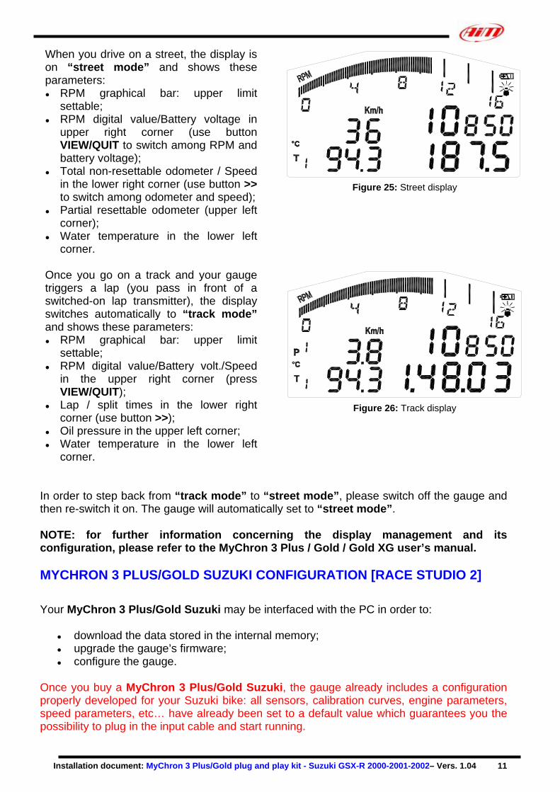
When you drive on a street, the display is on “street mode” and shows these parameters: ● RPM graphical bar: upper limit
settable; ● RPM digital value/Battery voltage in
upper right corner (use button VIEW/QUIT to switch among RPM and battery voltage);
● Total non-resettable odometer / Speed in the lower right corner (use button >> to switch among odometer and speed);
● Partial resettable odometer (upper left corner);
● Water temperature in the lower left corner.
Figure 25: Street display
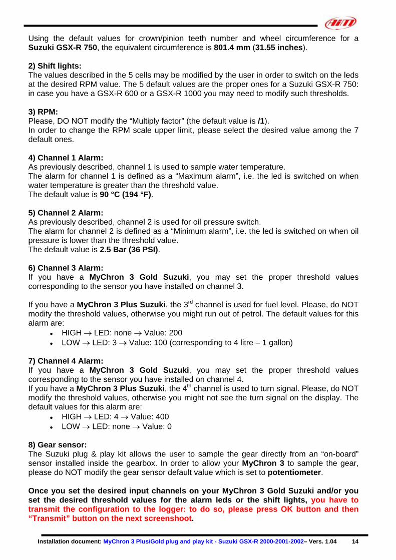
Once you go on a track and your gauge triggers a lap (you pass in front of a switched-on lap transmitter), the display switches automatically to “track mode” and shows these parameters: ● RPM graphical bar: upper limit
settable; ● RPM digital value/Battery volt./Speed
in the upper right corner (press VIEW/QUIT);
● Lap / split times in the lower right corner (use button >>);
● Oil pressure in the upper left corner; ● Water temperature in the lower left
corner.
Figure 26: Track display
In order to step back from “track mode” to “street mode”, please switch off the gauge and then re-switch it on. The gauge will automatically set to “street mode”. NOTE: for further information concerning the display management and its configuration, please refer to the MyChron 3 Plus / Gold / Gold XG user’s manual. MYCHRON 3 PLUS/GOLD SUZUKI CONFIGURATION [RACE STUDIO 2] Your MyChron 3 Plus/Gold Suzuki may be interfaced with the PC in order to:
● download the data stored in the internal memory; ● upgrade the gauge’s firmware; ● configure the gauge.
Once you buy a MyChron 3 Plus/Gold Suzuki, the gauge already includes a configuration properly developed for your Suzuki bike: all sensors, calibration curves, engine parameters, speed parameters, etc… have already been set to a default value which guarantees you the possibility to plug in the input cable and start running.

Installation document: MyChron 3 Plus/Gold plug and play kit - Suzuki GSX-R 2000-2001-2002– Vers. 1.04 12
Anyway, if you wish to change, for instance, the RPM upper value or the shift lights, if you wish to add a potentiometer sensor or a gyroscope on your MyChron 3 Gold Suzuki and you need to calibrate them, if you change the crown or the pinion with a “different teeth number” one, you need to use our software Race Studio 2. The CD-ROM including software, USB drivers, installation documentation and user’s manual is included in the MyChron 3 Plus/Gold Suzuki kit. If you have any doubt concerning the software or the USB drivers installation, please refer to the installation manuals included in the CD-ROM. The following table shows the input channels for both MyChron 3 Plus Suzuki and MyChron 3 Gold Suzuki. Please note that MyChron 3 Plus has no free input channels (i.e. the 4 input channels are sampled from the “stock” wiring and there are no “free cable-connectors” for external sensors), while MyChron 3 Gold has 2 free input channels and a gyroscope input which need to be configured and calibrated through Race Studio 2 Software. MyChron 3 Plus Suzuki MyChron 3 Gold Suzuki
Ch. 1 Ch. 2 Ch. 3 Ch. 4
Water temperature Oil pressure switch Fuel level Turn signal
Ch. 1 Ch. 2 Ch. 3 Ch. 4 Gyroscope
Water temperature Oil pressure switch Free input ch. – use Race Studio 2 Free input ch. – use Race Studio 2 Use Race Studio 2
In order to correctly configure your gauge and to easily use Race Studio 2, please follow these instructions.
Run Race Studio 2 and select the “M3 Auto-Moto Plus/Gold/XG” pushbutton in the buttons toolbar. Press button “System manager” and then “New” button: the screenshot shown in Figure 27 will be prompted. Please, set all the configuration parameters (Logger type, vehicle name, speed, temperature and pressure unit of measure) and then press button OK.
Figure 27: Race Studio 2 – New configuration

Installation document: MyChron 3 Plus/Gold plug and play kit - Suzuki GSX-R 2000-2001-2002– Vers. 1.04 13
Once pressed OK button, the System manager window will be prompted on your monitor, as shown in Figure 28. In order to correctly configure the input channels, please select it among the available ones (in Figure 28, for instance, there are 2 available configuration: the yellow-highlighted is the selected one) and press button “Channels”.
Figure 28: Race Studio 2 – System manager window
The screenshot shown in Figure 29 will be prompted on your monitor. MyChron 3 Plus Suzuki: As previously described, this logger has no free input channels, so this page is just a summary and the user may not change anything. MyChron 3 Gold Suzuki: This logger has 2 free input channels, labelled as CH. 3 and CH. 4. By clicking in the correspondent cell (row “CH 3 / CH. 4” and column “Sensor type”) you will be able to set the input channel among a long list of pre-defined sensors or, if you wish, you may set a user-defined sensor selecting “custom sensor manager”. Moreover, you may set the channel name and the sampling frequency.
Figure 29: Race Studio 2 – Input channels window
Once all sensors have been correctly set, please press button “Configuration”. Configuration window (Figure 30) allows You to set shift lights and alarms threshold value, to change unit of measure, speed parameters, etc.. 1) Speed: The speed sensor on your Suzuki bike is installed on the jackshaft which connects the gearbox to the pinion. The number of magnets installed on this jackshaft is 4. The wheel circumference written in the proper cell is an “equivalent circumference” calculated using the following formula: Figure 30: Race Studio 2 – Configuration window
c
p
NNCircumfWheel
CircumfEquiv*
= where Np = Pinion teeth number - Nc = Crown teeth number
Installation document: MyChron 3 Plus/Gold plug and play kit - Suzuki GSX-R 2000-2001-2002– Vers. 1.04 14
Using the default values for crown/pinion teeth number and wheel circumference for a Suzuki GSX-R 750, the equivalent circumference is 801.4 mm (31.55 inches). 2) Shift lights: The values described in the 5 cells may be modified by the user in order to switch on the leds at the desired RPM value. The 5 default values are the proper ones for a Suzuki GSX-R 750: in case you have a GSX-R 600 or a GSX-R 1000 you may need to modify such thresholds. 3) RPM: Please, DO NOT modify the “Multiply factor” (the default value is /1). In order to change the RPM scale upper limit, please select the desired value among the 7 default ones. 4) Channel 1 Alarm: As previously described, channel 1 is used to sample water temperature. The alarm for channel 1 is defined as a “Maximum alarm”, i.e. the led is switched on when water temperature is greater than the threshold value. The default value is 90 °C (194 °F). 5) Channel 2 Alarm: As previously described, channel 2 is used for oil pressure switch. The alarm for channel 2 is defined as a “Minimum alarm”, i.e. the led is switched on when oil pressure is lower than the threshold value. The default value is 2.5 Bar (36 PSI). 6) Channel 3 Alarm: If you have a MyChron 3 Gold Suzuki, you may set the proper threshold values corresponding to the sensor you have installed on channel 3. If you have a MyChron 3 Plus Suzuki, the 3rd channel is used for fuel level. Please, do NOT modify the threshold values, otherwise you might run out of petrol. The default values for this alarm are:
● HIGH → LED: none → Value: 200 ● LOW → LED: 3 → Value: 100 (corresponding to 4 litre – 1 gallon)
7) Channel 4 Alarm: If you have a MyChron 3 Gold Suzuki, you may set the proper threshold values corresponding to the sensor you have installed on channel 4. If you have a MyChron 3 Plus Suzuki, the 4th channel is used to turn signal. Please, do NOT modify the threshold values, otherwise you might not see the turn signal on the display. The default values for this alarm are:
● HIGH → LED: 4 → Value: 400 ● LOW → LED: none → Value: 0
8) Gear sensor: The Suzuki plug & play kit allows the user to sample the gear directly from an “on-board” sensor installed inside the gearbox. In order to allow your MyChron 3 to sample the gear, please do NOT modify the gear sensor default value which is set to potentiometer. Once you set the desired input channels on your MyChron 3 Gold Suzuki and/or you set the desired threshold values for the alarm leds or the shift lights, you have to transmit the configuration to the logger: to do so, please press OK button and then “Transmit” button on the next screenshoot.
Installation document: MyChron 3 Plus/Gold plug and play kit - Suzuki GSX-R 2000-2001-2002– Vers. 1.04 15
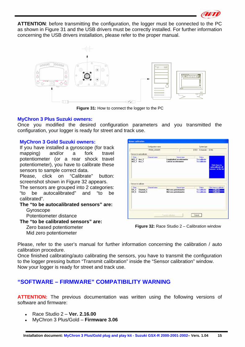
ATTENTION: before transmitting the configuration, the logger must be connected to the PC as shown in Figure 31 and the USB drivers must be correctly installed. For further information concerning the USB drivers installation, please refer to the proper manual.
Figure 31: How to connect the logger to the PC
MyChron 3 Plus Suzuki owners: Once you modified the desired configuration parameters and you transmitted the configuration, your logger is ready for street and track use.
MyChron 3 Gold Suzuki owners: If you have installed a gyroscope (for track mapping) and/or a fork travel potentiometer (or a rear shock travel potentiometer), you have to calibrate these sensors to sample correct data. Please, click on “Calibrate” button: screenshot shown in Figure 32 appears. The sensors are grouped into 2 categories: “to be autocalibrated” and “to be calibrated”. The “to be autocalibrated sensors” are:
Gyroscope Potentiometer distance
The “to be calibrated sensors” are: Zero based potentiometer Mid zero potentiometer
Figure 32: Race Studio 2 – Calibration window
Please, refer to the user’s manual for further information concerning the calibration / auto calibration procedure. Once finished calibrating/auto calibrating the sensors, you have to transmit the configuration to the logger pressing button “Transmit calibration” inside the “Sensor calibration” window. Now your logger is ready for street and track use.
“SOFTWARE – FIRMWARE” COMPATIBILITY WARNING ATTENTION: The previous documentation was written using the following versions of software and firmware:
● Race Studio 2 – Ver. 2.16.00 ● MyChron 3 Plus/Gold – Firmware 3.06
Installation document: MyChron 3 Plus/Gold plug and play kit - Suzuki GSX-R 2000-2001-2002– Vers. 1.04 16
If you use an “old” firmware version (earlier than 1.63) and a “new” software one (for instance 2.15.05 or 2.16.00), you might incur in a software – firmware incompatibility. The problem you will experience is that the firmware is too old to manage the new “on-board” bike sensors, like turn signal, oil pressure switch and fuel level and so you will not be able to see the leds corresponding to channels CH. 2 – CH. 3 – CH. 4 correctly switch on/off. Moreover, the old firmware does not manage the second virtual dashboard (see page 8 – Firmware for MyChron 3 Plus/Gold GSX-R). The solution for this problem is to:
● Upgrade the firmware of your MyChron 3 Plus/Gold to a version greater (or equal) than 3.06
The last version of firmware (and the last version of software), is freely downloadable from our website – click here.