Survey on Visual Servoing for Manipulationdanik/VSpapers/report.pdf · Survey on Visual Servoing...
58
Survey on Visual Servoing for Manipulation Danica Kragic and Henrik I Christensen Centre for Autonomous Systems, Numerical Analysis and Computer Science, Fiskartorpsv. 15 A 100 44 Stockholm, Sweden {danik, hic}@nada.kth.se
Transcript of Survey on Visual Servoing for Manipulationdanik/VSpapers/report.pdf · Survey on Visual Servoing...

Survey on Visual Servoing for Manipulation
Danica Kragic and Henrik I ChristensenCentre for Autonomous Systems,
Numerical Analysis and Computer Science,Fiskartorpsv. 15 A
100 44 Stockholm, Swedendanik, [email protected]

Contents
1 Abstract 3
2 Introduction 4
3 Background 5
4 Categorization 8
5 Visual-Motor Model Estimation 105.1 A-priori Known Models (Calibrated Models) . . . . . . . . . . . 11
5.1.1 Position based control . . . . . . . . . . . . . . . . . . . 115.1.2 Image based control . . . . . . . . . . . . . . . . . . . . 165.1.3 2 1/2D visual servoing . . . . . . . . . . . . . . . . . . . 24
5.2 Visual-Motor Model Estimation . . . . . . . . . . . . . . . . . . 25
6 Obtaining Visual Measurements 276.1 Monocular Vision . . . . . . . . . . . . . . . . . . . . . . . . . . 286.2 Binocular Vision . . . . . . . . . . . . . . . . . . . . . . . . . . 316.3 Redundant Camera Systems . . . . . . . . . . . . . . . . . . . . 34
7 Control Generation and System Design 35
8 Visually Guided Systems - A Summary 36
9 Discussion 40
2

1 Abstract
Vision guided robotics has been one of the major research issue for more than threedecades. The more recent technological development facilitated the advancementin the area which has resulted in a number of successful and even commercialsystems using off–the–shelf hardware. The applications of visually guided systemsare many: from intelligent homes to automotive industry. However, one of the openand commonly stated problems in the area is the need for exchange of experiencesand research ideas. In our opinion, a good starting point for this is to advertisethe successes and propose a common terminology in form of a survey paper. Thepaper concentrates on different types of visual servoing: image based, positionbased and 2 1/2D visual servoing. Different issues concerning both the hardwareand software requirements are considered and the most prominent contributions arereviewed. The proposed terminology is used to introduce a young researcher andlead the experts in the field through a three decades long historical field of visionguided robotics. We also include a number of real–world examples from our ownresearch providing not only a conceptual framework but also illustrating most ofthe issues covered in the paper.
3
2 Introduction
Using visual feedback to control a robot is commonly termed visual servoing,(Hutchinson et al. 1996). Visual (image based) features such as points, lines andregions can be used to, for example, enable the alignment of a manipulator / grip-ping mechanism with an object. Hence, vision is a part of a control system whereit provides feedback about the state of the environment. Visual servoing has beenstudied in various forms for more than three decades starting from simple pick–and–place tasks to todays real-time, advanced manipulation of objects. In terms ofmanipulation, one of the main motivations for incorporating vision in the controlloop was the demand for increased flexibility of robotic systems.
One of the open and commonly stated problems in the area is the need forexchange of experiences and research ideas.
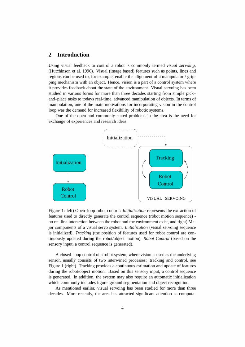
Initialization
RobotControl
Initialization
Tracking
Control
Robot
VISUAL SERVOING
Figure 1: left) Open–loop robot control: Initialization represents the extraction offeatures used to directly generate the control sequence (robot motion sequence) -no on–line interaction between the robot and the environment exist, and right) Ma-jor components of a visual servo system: Initialization (visual servoing sequenceis initialized), Tracking (the position of features used for robot control are con-tinuously updated during the robot/object motion), Robot Control (based on thesensory input, a control sequence is generated).
A closed–loop control of a robot system, where vision is used as the underlyingsensor, usually consists of two interwined processes: tracking and control, seeFigure 1 (right). Tracking provides a continuous estimation and update of featuresduring the robot/object motion. Based on this sensory input, a control sequenceis generated. In addition, the system may also require an automatic initializationwhich commonly includes figure–ground segmentation and object recognition.
As mentioned earlier, visual servoing has been studied for more than threedecades. More recently, the area has attracted significant attention as computa-
4

tional resources have made real-time deployment possible. At the same time, ro-bust methods for real-world scenarios have gradually enabled progress on realisticproblems in terms of complexity. A problem that has become apparent with the in-crease in the number of contributions to visual servoing is a lack of a terminologyand taxonomy for the approaches presented. Visual servoing is used in a rich vari-ety of applications such as lane tracking for cars, navigation for mobile platformsand manipulation of objects. The most general of these applications is manipu-lation of objects which requires detection of objects, segmentation, recognition,servoing, alignment, grasping. Although many approaches do not address all ofthese aspects, the manipulation task provides a global framework for considerationof the diverse research on servoing.
The literature contains an excellent introduction to visual servoing in form of atutorial by (Hutchinson et al. 1996). The tutorial is however five years old by nowand significant work has been reported since then. In addition, there is a lack of asurvey of the vast literature available. Consequently, in this paper a comprehensivesurvey of the literature is provided. As the basis for the presentation, a taxonomyof approaches to visual servoing is defined and the key factors influencing visualservoing are identified. The various approaches to visual servoing are illustratedby examples that primarily are taken from our own research. The remainder ofthe survey starts with a Section 3 that provides an introduction to visual servoingmainly outlining the history and major milestones in the development of visualservoing techniques from its very beginning. From this, the major steps involvedin servoing are introduced in Section 4. Each of the steps are then outlined: i)approaches to visual-motor estimation in Section 5, ii) strategies to feature/stateestimation in Section 6, and iii) methods for control generation in Section 7. Thesethree steps provide the basic dimensions in our taxonomy for visual servoing. Theliterature is then reviewed and the presented approaches are classied and discussedin relation to the proposed taxomony 8. The final section provides a discussion onthe open issues and trends in the field of visual servoing.
3 Background
The following distinction is usually made between two different ways of usingvisual information in a robot system:
• Open–loop Robot ControlExtraction of image information and control of a robot are two separate taskswhere at first image processing is performed followed by the generation ofa control sequence, (see Figure 1, left). A typical example is to recognizethe object to be manipulated by matching image features to a geometricalmodel of the object and compute its position and orientation (pose) relativeto the camera (robot) coordinate system. This absolute pose, Cartesian–space information is used to move the robot to the desired pose relative tothe object. To estimate the pose of the object, the model of the object must be
5

available. To move the robot based on the visual information extracted in thecamera frame, the camera(s) has to be calibrated with respect to the robot. Inaddition, the robot direct and inverse kinematic models have to be availableto convert Cartesian–space robot positions into joint–space configurations.The robot can then execute the task by performing “blind” movements whichassumes that the environment remains static after the robot has started tomove (open–loop approach).
• Visual ServoingIn 1979, Hill and Park, (Hill & Park 1979) introduced the term visual ser-voing to distinguish their approach from earlier work. In 1980 the fol-lowing taxonomy of visual servo systems was introduced in (Sanderson &Weiss 1980):1. Dynamic look-and-move systems: These systems perform the control ofthe robot in two stages: the vision system provides input to robot controllerthat then uses joint feedback to internally stabilize the robot. As pointed outby (Hutchinson et al. 1996) nearly all of the reported systems adopt this ap-proach.2. Direct visual servo systems1: Here, visual controller directly computesthe input to the robot joints and robot controller is eliminated.
A typical visual servoing task usually includes some form of i) “positioning”such as aligning the robot/gripper with the target, or ii) “tracking” or remaininga constant relationship between the robot and the moving target. In both cases,image information is used to measure the error between the current location of therobot and its reference or desired location. Image information used to performthe task is either i) two dimensional expressed by using image plane coordinates,or ii) three dimensional where camera/object model is employed to retrieve poseinformation with respect to the camera/world/robot coordinate system. So, therobot is controlled either using image information as two- or three dimensionalwhich classifies the visual servo systems additionally as:
1. Position-based visual servo systemsThese systems retrieve the three-dimensional information about the scenewhere known camera model (usually in conjunction with a geometric modelof the target) is used to estimate the position and the orientation (pose) ofthe target with respect to the camera (world, robot) coordinate system. Thepositioning or tracking task is defined in the estimated (3D) pose space.
2. Image-based visual servo systemsHere, 2D image measurements are used directly to estimate the desired move-ment of the robot. Typical tasks like tracking and positioning are performed
1This term is adopted from (Hutchinson et al. 1996). Sanderson and Weiss used the term visualservo for this type of systems but that introduces a certain confusion since the term has been widelyused for all types of closed–loop vision based control systems.
6

by reducing the image distance error between a set of current and desiredimage features in the image plane.
3. 2 1/2 D visual servo systemsHere, a combination of previous two approaches is used and the error to beminimized is specified both in the image and in the pose space.
Hence, the general idea behind visual servoing is to derive the relationshipbetween the robot and the sensor space and estimate a velocity screw associatedwith the robot frame needed to minimize the specified error.
Visual servoing borrows from many different research areas including robotmodeling (geometry, kinematics, dynamics), real–time systems, control theory,systems (sensor) integration, computational vision (image processing, structure–from–motion, camera calibration). As pointed out in (Corke 1994), there are manydifferent ways of classifying the reported results: based on sensor configuration,number of cameras used, generated motion command (2D,3D), scene interpreta-tion, underlying vision algorithms. Given the vast amount of published materialwithin and across different research areas, the next section proposes a commontaxonomy. The proposed taxonomy is used to reference a number of contributionsregarding visual servoing.
3D WORLD
GE
NE
RA
TIO
NC
ON
TR
OL
TA
SK
PL
AN
NIN
G
y*
STATEESTIMATION x
uROBOT
y
task space T
sensor space S
Figure 2: The major processes involved in a vision based control of a robot. Arelative Euclidian motion of the robot is defined as the input u in the task space ofthe robot, T . x represents the state vector, y is the measurement vector and y∗ isthe vector of desired measurements in the sensor space, S .
7

4 Categorization
Let us assume, according to Figure 2, a robotic system that operates in a 3Dworld. The relative Euclidian motion of the robot is produced by the input u inits task space, T . Since, in our context, T represents the set of all poses that therobot’s end–effector can attain, it is denoted by TG ⊆ SE(3). If the robot is con-trolled using six-degree Cartesian velocity representation, the control input vectoris u = [VX VY VZ ωX ωY ωZ ]T ∈ R (6), the velocity screw of the robot. The statevector, x, may, for example, represent the pose of the target, X = [R, t], usuallyrepresented by translation and rotation parameters, q = [tX tY tZ φ ψ γ]T ∈ R (6).The measurement vector y may, for example, contain the pose of the target or im-age point coordinates, y = [ [x1 y1], ...[xk/2 yk/2] ]T ∈ R (k) while y∗ represents thevector of desired measurements.
A visual servoing task is also referred to as a task function, (Chaumette et al.1991) or a control error function. Representing some desired set of features by y∗
and the set of current features with y, the objective of visual servoing is to regulatethe task function to zero. When the task is completed, the following holds:
e(y∗−y) = 0. (1)
The task function is also referred to as kinematic error function or virtual kine-matic constraint in the case of position based visual servoing and image errorfunction in the case of image based visual servoing, (Hutchinson et al. 1996).
For the discussion, the research issues are divided into three parts:
• Visual-Motor Model Estimation(Corke & Good 1996) make a distinction between visual kinematic and vi-sual dynamic control where the former deals with how a manipulator shouldmove in response to the perceived visual information, while the latter ap-proach accounts for the dynamic effects that usually occur in a robotic sys-tem. Accordingly, the basic concern here is to classify systems based onthe estimation of visual-motor model, see Figure 4: i) systems where visual-motor model is known a–priori, or ii) estimated2 .
• State EstimationHere, the issues related to visual measurements are addressed: camera con-figuration, number of cameras and commonly adopted image processingtechniques. Visual measurements define the extraction of visual informa-tion such as optical flow, position and orientation of an object or featureslike points or lines. The following sensor-robot configurations may be em-ployed: eye–in–hand, stand alone (fixed) camera system or their combina-tion, see Figure 3. The estimation may be performed in image space (2D)
2The further division of the former systems to position, image or 2 1/2D based is just for thesimplicity reasons. This does not exclude the issue that the latter systems will also use one of theseapproaches during the control of the robot.
8

and used together with camera model to retrieve the 3D information. Forsystems that utilize image (2D) information directly, the task function is nor-mally also defined in image space. However, this is not the case in generalfor systems that compute the complete 3D pose of the target where the taskfunction may be expressed both in 2D or in 3D.
• Control GenerationControl synthesis is closely related to the first issue, visual-motor modelestimation. The accuracy of the model will directly affect the rate of con-vergence of the system. In this section, some of the work related to theunderlying control design is briefly reviewed.
In the next section, visual servo systems are categorized with respect to theestimation of the visual–motor model, see Figure 4. For the systems wherethe geometry or kinematics of the manipulator is known and used in theservoing process, it is assumed that the visual–motor model is known a–priori. Depending on the accuracy of the model and the specification of thetask the systems are additionally divided into position, image and 2 1/2Dbased systems. The other group of systems estimate the visual–motor modeleither analytically or by learning.
1 2
EYE−IN−HAND STAND−ALONE EYE−IN−HAND STAND−ALONE
number of cameras
CAMERA−ROBOT CONFIGURATION
>2
VM5VM1 VM4VM3VM2
Figure 3: Camera–robot configurations used in visual servoing control (from left toright): VM1 monocular eye–in–hand, VM2 monocular stand–alone, VM3 binocu-lar eye–in–hand, VM4 binocular stand–alone and VM5 redundant camera system.
9

KNOWN A−PRIORI
POSITION BASED 2 1/2D IMAGE BASED
VISUAL−MOTOR MODEL ESTIMATION
ESTIMATED
BY LEARNINGANALYTICALLY
Figure 4: Visual servo systems with respect to the visual–motor model estimation.Systems where visual-motor model is known a priori use the kinematic modelof the robot, camera parameters as well as different levels of calibration betweenthe camera and the robot system to estimate the desired robot motion. On theother hand, there are systems that estimate visual-motor model either by learning oranalytically, allowing for the control without the knowledge of the robot geometry.
5 Visual-Motor Model Estimation
To classify systems according to the estimation of visual-motor model, the tax-onomy as presented in Figure 4 and Figure 5 is adopted. If the robot forwardor inverse kinematics are known, the differential changes between the joint andCartesian space are computed using robot Jacobian. These systems are classifiedas systems where visual-motor model is known a-priori. Depending on the feed-back representation mode and level of calibration between the camera and the robotframe, the visual servo systems are classified as position based, image based or 21/2 D systems.
Most of the early visual servo systems relied on a accurate calibration of thesystem and performed tasks using the position based approach. Since the process ofcalibration could be tedious, error prone or even impossible to perform, approachesthat avoid the calibration step or where a some knowledge of the calibration is suf-ficient, became appealing. Hence, image based servo systems are usually preferredto position based systems since they may carry out the task without the accuratecalibration. However, some knowledge of the transformation between the sensorand the robot frame is still required.
On the other hand, there are systems that completely obviate the calibrationstep and estimate the visual-motor model either on– or off–line. The visual-motormodel may be estimated: a) analytically (nonlinear least square optimization) orb) by learning or training. In addition, as presented in Figure 5, the systems mayestimate an image Jacobian and use the known robot model or a coupled robot-image Jacobian may be estimated.
10

JOINTSPACE
IMAGECARTESIANPLANESPACE
Image JacobianRobot Jacobian
Coupled Image−Robot Jacobian
Figure 5: Some of the visual servo systems use the knowledge of robot kinemat-ics (robot Jacobian) and then the image Jacobian relates the differential changesbetween image features and the robot’s Cartesian velocities or incremental posechanges. On the other hand, a coupled robot-image Jacobian relates the differen-tial changes between the robot joints and image features.
5.1 A-priori Known Models (Calibrated Models)
As already mentioned, we classify visual servoing approaches based on the feed-back representation mode. These can be: i) position based, ii) image based andiii) 2 1/2 D visual servo systems. We now present the basic ideas and discuss thecharacteristics of each of them.
5.1.1 Position based control
Position based visual servoing is usually referred to as a 3D servoing control sinceimage measurements are used to determine the pose of the target with respect tothe camera or some common world frame. The error between the current andthe desired pose of the target is defined in the task (Cartesian) space of the robot.Hence, the error is a function of pose parameters, e(X).
Two examples of position based servoing are presented in Figure 6. The fig-ure on the left shows an example where the camera is controlled from its currentpose, CXO, so to achieve the desired pose with respect to the object, CX∗
O. In thisexample, the camera is attached to the last link of a manipulator and observes astatic or a moving target, and the model of the object is used to estimate its pose.The figure on the right shows an example of a static camera and a moving object.It is assumed here that the object is held by a manipulator which is then controlledto, again, achieve the desired pose between the object and the camera. Since thepose of the object is estimated relative to the camera, the transformation betweenthe robot and the camera has to be known to generate the required motion of themanipulator.
These examples demonstrate two main reasons why the position based visualservoing is usually not adopted for servoing tasks: i) it requires the estimation ofthe pose of the target or which requires some form of a model, and ii) to estimate
11

Z
Y
X
Z
YX
*o
c
co
X
X
Z
X
Y
Y
Z
X
Y
X
Z
Y
X
Z
*o
c
ocX
X
Figure 6: Two examples of position based visual servoing control: left) an exampleof an eye–in–hand camera configuration where the camera/robot is servoed fromthe CXO (current pose) to the CX∗
O (desired pose), and right) a monocular, stand–alone camera system used to servo a robot held object from its current to the desiredpose.
the desired velocity screw of the robot and in order to achieve accurate positioning,it requires precise system calibration (camera, camera/robot). A block diagram ofthe position based visual servoing approach is presented in Figure 7. Here, thedifference in pose between the desired and the current pose represents an errorwhich is then used to estimate the velocity screw for the robot, q = [V;Ω]T , so tominimize the error.
An Example: Align and track task
Let us assume that the task is to first achieve and maintain a constant pose betweenthe object and robot end–effector, OX∗
G. According to (Hutchinson et al. 1996), this
BASED CONTROL
POSITION(CARTESIAN)
FEATURE
EXTRACTIONESTIMATION
POSE3D CAMERA
ROBOT+
−
V, Ωco *
co
X
X
Figure 7: A block diagram of the position based visual servoing: the pose of thetarget is estimated, CXO and compared to the reference (desired) pose, CX∗
O. Thisis then used to estimate the velocity screw, q = [V; Ω]T , for the robot so to mini-mize the error.
12

is considered as an EOL (endpoint open loop) system, since only the target objectis observed during the servoing sequence.
G
*RXG
*OXG
R
CX
COX
OX
GRX
Figure 8: Relevant coordinate frames and their relationships for the “Align–and–track” task where a stand–alone camera system is used to guide the robot to thedesired pose with respect to the object. Here, OX∗
G represents the desired posebetween the object and the end–effector while OXG represents the current (or ini-tial) pose between them. To perform the task using the position based servoingapproach, the transformation between the camera and the robot coordinate frames,CXR, has to be known. The pose of the end-effector with respect to the robot basesystem, RXG is known from the robot’s kinematics.
The manipulator is controlled in the end-effector frame. According to Figure 8,if OXG = OX∗
G then RXG = RX∗G. The error function to be minimized may then
be defined as the difference between the current and the desired end-effector pose:
∆ RtG = RtG −Rt∗G
∆ RθG = RθG −Rθ∗G
(2)
Here, RtG and RθG are known from the forward kinematics equations and Rt∗G andRθ∗G have to be estimated. The homogeneous transformation between the robot anddesired end–effector frame is given by:
RX∗G = RXC
CXOOX∗
G (3)
The pose between the camera and the robot is estimated off–line 3 and the pose ofthe object relative to the camera frame is estimated using the model based tracking
3The homogeneous transformation relating the camera and the robot coordinate frames was ob-tained off–line. A LED was placed at the end of the manipulator chain and its position in the im-age was estimated while the manipulator moved through a number of predefined points. Assum-ing the knowledge of the camera intrinsic parameters, the pose estimation approach presented in(Kragic 2001) was used to estimate the transformation between the robot and the camera.
13

Figure 9: A sequence from a 6DOF visual task: From an arbitrary starting position(upper left), the end–effector is controlled to a predefined reference position withrespect to the target object, (upper right). When the object starts moving, the visualsystem tracks the pose of the object. The robot is then controlled in a position basedframework to remain a constant pose between the gripper and the object frame.
system presented in (Kragic 2001). Expanding the transformations in (Eq. 3) weget:
Rt∗G = RRCCRO
Ot∗G + RRCC tO + RtC (4)
where CRO and C tO represent predicted values obtained from the tracking algo-rithm. Similar expression can be obtained for the change in rotation by using theaddition of angular velocities (see Figure 8) and (Craig 1989):
RΩ∗G = RΩC + RRC
CΩO + RRCCRO
OΩ∗G (5)
Assuming that the RRC and CRO are slowly varying functions of time, integrationof RΩ∗
G gives (Wilson et al. 1996):
Rθ∗G ≈RθC + RRC
CθO + RRCCRO
Oθ∗G (6)
Substituting (Eq. 4) and (Eq. 6) into (Eq. 2) yields:
∆ RtG = RtG −RtC −
RRCC tO −
RRCCRO
Ot∗G∆ RθG ≈
RθG −RθC −
RRCCθO −
RRCCRO
Oθ∗G(7)
14

which represents the error to be minimized:
e =
[
∆ RtG
∆ RθG
]
(8)
After the error function is defined, a simple proportional control law is used todrive the error to zero. The velocity screw of the robot is defined as4:
q ≈ Ke (9)
By using the estimate of object’s pose and defining the error function in terms ofpose, all six degrees of freedom of the robot are controlled.
A few example images obtained during one of the experimental sequences areshown Figure 9. From an arbitrary starting position, the end–effector is moved toa predefined stationing pose with respect to the target object (first row, left). Whenthe object starts to move, the visual system estimates its pose, CXO. The error isestimated according to (Eq. 8) and used to estimate the velocity screw of the robotusing (Eq. 9).
In general, the main advantage of this approach is that the camera/robot trajec-tory is controlled directly in the Cartesian coordinates. This allows easier trajectoryplanning for e.g., obstacle avoidance. However, especially in the case of eye–in–hand camera configuration, image features used for pose estimation may get out ofthe image. The reason is that the control law does not incorporate any constraintswhen it comes to image plane feature coordinates. If the camera is only coarselycalibrated (i.e., the camera parameters are approximately known), the current anddesired camera poses will not be accurately estimated which will thus lead to apoor performance (in terms of accuracy) or even a complete failure of the visualservoing task. One of the solutions to this problem is to design the servo systemas an endpoint closed loop system where both the target and the end–effector areobserved during the execution of the task (Hutchinson et al. 1996).
There are examples of utilizing both eye-in-hand and stand-alone camera con-figurations for position based control. The examples range from planar positioningsystems (Allen et al. 1993), to systems that use object models and demonstrate fullpose determination in real–time, see for example (Wilson et al. 1996), (Wunsch &Hirzinger 1997) and (Drummond & Cipolla 1999b).
An extensive evaluation of the position based visual servoing with respect totrade–offs between the requirements of speed, accuracy and robustness is given in(Wilson et al. 2000). Since most of the reported systems adopting this approachconcentrate on the extraction of the visual information rather than on the analysisof sensitivity, etc., we provide additional references in Section 6. The section alsoprovides a number of pointers related to the pose estimation problem, structure–from–motion, and stereo reconstruction problems.
15

f
Y
Z
X
Oc
f
ff
1
2
3
4
*
*
*
*
f
f
4f 3f
2
1
c c
c
c
Figure 10: An example of image based visual servoing. Let us assume a case ofa static camera and a robot holding the object. A number of feature points on theobject is tracked and used to generate a vector of current measurements, fc. Thevector of reference measurements is denoted f∗. The error function is defined as afunction of distance between these measurements, e = fc
− f∗. This error functionis then updated in each frame and used used together with the image Jacobian toestimate the control input to the robot.
5.1.2 Image based control
Image based visual servoing involves the estimation of the robot’s velocity screw,q, so as to move the image plane features, fc, to a set of desired locations, f∗, (Hageret al. 1995), (Malis et al. 1998), (Chaumette et al. 1991). Image based visualservoing control involves the computation of the image Jacobian or the interactionmatrix, (Hutchinson et al. 1996), (Espiau et al. 1992), (Hashimoto & Noritsugu1998). The image Jacobian represents the differential relationship between thescene frame and the camera frame (where either the scene or the camera frame isusually attached to the robot):
J(q) =[
δfδq
]
=
δ f1(q)δq1
. . . δ f1(q)δqm
.... . .
...δ fk(q)
δq1. . . δ fk(q)
δqm
(10)
where q represents the coordinates of the end-effector in some parameterization ofthe task space T , f [ f1, f2, ..., fk ] represents a vector of image features, m is thedimension of the task space T and k is number of image features. The relationshipbetween a velocity screw associated to the manipulator and the image parametersrates of change is given by:
f = J q (11)4It is straightforward to estimate the desired velocity screw in the end–effector coordinate frame.
16

Using a classical perspective projection model with unit focal length, the relation-ship between an image point velocity and a 3D velocity screw is given by:
[
xy
]
=
[ 1Z 0 −
xZ xy (1+ x2) −y
0 1Z −
yZ −(1+ y2) xy x
]
q (12)
where Z represents the 3D distance of the point with respect to the camera. Im-age based visual servo systems express the control error function directly in 2Dimage space. If image positions of point features are used as measurements, theerror function is defined simply as a difference between the current and the desiredfeature positions:
e(f) = fc− f∗ (13)
The most common approach to generate the control signal for the robots is theuse of a simple proportional control5 (see (Papanikolopoulous & Khosla 1993) and(Hashimoto, Ebine & Kimura 1996) for an optimal control approach):
u = q = KJ†e(f) (14)
where J† is the (pseudo-)inverse of the image Jacobian and K is a constant gainmatrix.
Figure 10 shows an example of an image based visual servoing approach whereit is assumed that the camera is static and that it observes the robot holding anobject. A number of feature points on the object are tracked and used to generatea vector of current measurements, fc. The vector of reference measurements isdenoted f∗. The error function is defined as a function of distance between thesemeasurements according to (Eq. 13). This error function is then updated in eachframe and used together with the image Jacobian to estimate the control input tothe robot using (Eq. 14).
The vector of reference measurements, f∗, is usually generated using a so called“teach by showing” approach where the robot is first moved to a desired positionand the image coordinates of feature positions are recorded. After that, the robot ismoved to some other, initial position and visual tracking is initiated. In a closed–loop manner, the robot is controlled while moving to the desired or “taught” po-sition while tracking the features and estimating fc. In (Horaud et al. 1998), thedesired position between the gripper and an object is defined through a projectiverepresentation and the new goal image is computed when the target changes insteadof being learnt manually.
According to (Eq. 12), the estimation of the image Jacobian requires knowl-edge of the camera intrinsic and extrinsic parameters. Extrinsic parameters alsorepresent a rigid mapping between the scene or some reference frame and the cam-era frame. If one camera is used during the servoing process, the depth informa-tion needed to update the image Jacobian is lost. Therefore, many of the existingsystems usually rely on a constant Jacobian which is computed for the desired
5With an assumption that the target is motionless.
17

camera/end–effector pose. This is one of the drawbacks of this approach, sincethe convergence is ensured only around the desired position. This problem may besolved by adaptive estimation of the depth (Papanikolopoulous & Khosla 1993),determining depth from the a–priori known relationship of the features or using astructure from motion approach if the camera motion can be measured, (Longuet-Higgins 1981), (Jerian & Jain 1991). However, using variable depth may result ininadequate camera/robot motions leading to possible local minima and singularitiesand ultimately unstable behavior of the robot, (Chaumette 1997). If a stand–alonecamera system is used, and if the calibration between the robot and the cameraframe is (partially) known, the depth required for the image Jacobian estimationcan be retrieved using the forward kinematics of the robot and calibration parame-ters. The image Jacobian matrix depends also on the type of features used and theservoing task itself (point-to-point positioning, point-to-line positioning, etc.), see(Hager 1997) for examples.
In general, a minimum of three feature points are necessary to control the po-sition and orientation of the camera in 3D space (assuming that an eye–in–handconfiguration is used). However, there are two cases of singular configurationsfor this case, (Michel & Rives 1993): i) if the three points are aligned, and ii) ifthe optical center lies on the cylinder which includes the three points and whoseaxis is perpendicular to the plane containing all three points. It has been proven in(Hashimoto & Noritsugu 1998), that the image Jacobian becomes full rank in thecase of four points if three of them are not aligned.
Compared to an eye–in–hand configuration where the object to be manipulatedis usually not in the field of view of the camera, a stand alone camera can easilyobserve the object and the gripper simultaneously (Hager 1997). If a stereo camerasystem is used, the following property may be used: zero disparity between a pointon the manipulator and a point on the object in two images means that these twopoints are same point in space. In other words, the error function is simultaneouslyminimized in two images. The image Jacobian is estimated by simply concate-nating two monocular image Jacobians. If the epipolar geometry of the camera isknown, depth estimation becomes trivial. In addition, imposing a line trajectory intwo images results in a line motion in 3D whereas in the case of one camera, anyplanar curve projects as a line in the image.
Image based visual servoing control is considered to be very robust with respectto camera and robot calibration errors (see (Hutchinson et al. 1996) and (Weisset al. 1987)). Coarse calibration only affects the rate of convergence of the controllaw in the sense that a longer time is needed to reach the desired position.
Example Tasks
Let us assume the following scenario:
Tasks: i) to execute an insertion task, ii) to grasp an object, or iii) to place anobject held by the end-effector to a pose defined in the image space,
18

Assumptions: i) no models of the objects are given, ii) an image based track-ing algorithm is available (which estimates 2D image positions of featurepoints), iii) a stereo stand–alone camera system is used during the executionof the tasks.
flc
f*l fr
*
frc
R
GR
XC
X
Figure 11: A schematic overview of a point–to–point positioning task using abinocular camera system. The error function is defined for the left, e l = fc
l − f∗l ,and the right image, er = fc
r − f∗r . To drive this error to zero the image Jacobian isestimated by stacking of a two monocular image Jacobians defined for each of thecameras. To control three translational degrees of freedom of the manipulator, it isenough to estimate the distance between two points in each image. This approachdoes not require accurate estimation of the transformation between the robot andthe camera coordinate systems, that is, CXR has to be only roughly known.
The examples presented in this section are to large extent motivated by thework presented in (Hager et al. 1995). No metric information about the object isused. Calibration insensitive positioning and alignment are performed by trackingsmall regions on the target and the end–effector. Although the examples shownare very basic and simple, they are necessary building blocks for more complexhand–eye tasks (Dodds et al. 1999).
Figure 11 shows an example of a task and setting used to perform a positioningtask using feedback from stereo vision. Here, the image based visual servoingapproach is used to minimize an error function defined directly in the image. Asit can be seen in the figure, there is a feature (in this case it is assumed that it is apoint feature) on the end–effector denoted fc
l and fcr for the left and the right image,
19

Figure 12: Example images obtained during the execution of the insertion task.
respectively. The position of the feature is tracked and used to design a control lawto bring that point to the position denoted f∗l and f∗r . The task is accomplished whenfc and f∗ coincide in both images.
The first task is to place a screwdriver in the hole on the upper side of the box,see Figure 12. The diameter of the hole is approximately 5mm. The screwdriveris held by the robot and a constant relationship between them is assumed (rigidityconstraint). A predefined configuration of the last three joints of the robot is usedand the robot holds the screwdriver vertically with respect to the table plane. Onlythree degrees of freedom of the robot are controlled corresponding to the positionaldegrees of freedom, T ⊆ R (3). In each image, the region around the tip of thescrewdriver is tracked and its position fl and fr is used to estimate the error:
el = fl − f∗ler = fr − f∗r
(15)
The desired positions f∗l and f∗r are chosen manually at the beginning of theservoing sequence. Using (Eq. 14), the relationship between the robot’s kinematicscrew and the observed speed of the image features in the left and right camerasrespectively is:
Kl el = Jl(q) Gq
Kr er = Jr(q) Gq(16)
20

Figure 13: Example images obtained during grasping of a toy car.
It has been suggested in (Hager 1997) that these two equations may be “stacked”yielding the following:
K e(f) = Jlr(q) Gq (17)
where f = [xl yl xr yr]T . It is obvious that the image Jacobian in (Eq. 17) obtained
by stacking two monocular image Jacobians cannot be directly inverted since it hasfour rows and six columns and rank three. The reason for the rank is that, due tothe geometry of the stereo system, y coordinates of the features will be the same inthe two images6. Hence, this measurement is redundant and can be discarded fromthe equation. Since in this case, only the translational degrees of freedom have tobe controlled, Gq = [VX VY VZ]T , it is enough to use the first three columns of theimage Jacobian. Now, the image Jacobian is a square, 3× 3 matrix and it can beinverted directly without using a left or right inverse. Therefore, the velocity screwof the robot is estimated using a simplified version of (Eq. 14).
Four example images obtained during the execution of the insertion task areshown in Figure 12 (images from one of the cameras are shown): the figure on theleft (first row) shows the first image where the initial feature position at the tip of thescrewdriver and the desired position on the box are chosen manually. The figure onthe right and the figure on the left (second row), show the intermediate images. Thelast figure (second row, right) shows the final stage of the task when the manipulator
6That is, although four measurements are provided by two cameras, the point has only threedegrees of freedom.
21

moves vertically down for a few centimeters showing that the insertion task wassuccessfully performed. Since it is assumed that the relationship between the end–effector and the tip of the screwdriver remains constant, this is an example of anendpoint closed loop system.
Another similar task is shown in Figure 13. The control is generated in thesame manner and the orientation of the car is known in advance. The image on theleft (first row) shows the initial position of the robot. The white rectangle representsa point on the end–effector tracked by the vision system. The cross represents thedesired position of the point. After the desired point is reached (first row, right), themanipulator moves vertically down a few centimeters and grasps the car (secondrow). Again, a point on the end–effector and on the object are observed makingthis an endpoint closed loop system. However, the task was somewhat simplified.Since this is an example of point–to–point positioning (as in the previous example),it allows us to estimate the translational velocity needed to bring the point on theend–effector to the desired point on the object. Hence, the orientation of the end–effector has to be set from the beginning to allow for the grasp to occur.
The third example considers an alignment of the wheels of a toy car with theroad, see Figure 14. The image coordinates of the wheels are denoted wl,r
1 and wl,r2
for left and right image respectively and an image line by ll,r . It has been shown in(Hager 1997) that given two image points on the line, p1 and p2, the equation ofthe line is given by:
l =L
√
L2x +L2
y
where L = p1 ×p2 (18)
Here, two tasks are simultaneously performed: point–to–line (w1 ∈ l) and point–to–point (w2 = p2) positioning. For any homogeneous vector p in the image, p · lis the distance between the point and the line. Thus, a positioning error between apoint wl,r and a line ll,r in left and right image respectively is defined as:
epl =
[
wl1 · l
l
wr1 · l
r
]
(19)
The Jacobian for point–to–line positioning is then estimated by again stacking twomonocular point–to–line Jacobians:
Jpl(w1, l) =
[
ll T
lr T
]
Jpp(w1) (20)
Concatenating the task error, (Eq. 19) and the image Jacobian, (Eq. 20) with thosefor w2 = p1 (given by (Eq. 15) and (Eq. 17)) the velocity screw of the robot isestimated using (Eq. 14).
The first image in Figure 14 shows a schematic overview of the task and therest of the images were obtained during the execution of the task. Here, the featurestracked in two images are the wheels of the car denoted w1 and w2 (in each image).The task is accomplished when the point p1 and w1 coincide in each image and thepoint w2 ∈ l.
22

p1
w2
w1 p1
w2 l
l
=
Figure 14: An example of positioning a car parallel to the road. Beside the posi-tioning, the car also has to be oriented so to be aligned with the direction of theroad. The first image shows a schematic overview of the task: the features trackedin two images are the wheels of the car denoted w1 and w2 (in each image). Theequation of the of line l representing the orientation of the road is estimated using(Eq. 18). For this purpose two points, p1 and p2, were manually chosen in eachimage at the beginning of the servoing sequence. The task is accomplished whenthe point p1 and w1 coincide in each image and the point w2 ∈ l.
23

(R,t)
ff * c
dd* c
*n*
PY
X
Z
Figure 15: A camera observing a plane from two positions: there is a linear trans-formation relating the coordinates of a point in two camera images. This transfor-mation is a 8DOF 3×3 matrix M which may be estimated using four or more pointcorrespondences. The homography can be written in terms of internal camera pa-rameters, A, the camera displacement between the views, X(R, t) and the equationof the plane (n,d) being viewed: fc = Mf∗ = A(R + tnT /d)A−1f∗. If the internalparameters, A, are known, the rotation R and the plane normal n can be fully re-covered from the homography. The translation t and the distance to the plane d canbe recovered only up to a scale, see (Faugeras 1993).
5.1.3 2 1/2D visual servoing
(Malis et al. 1998) present 2 1/2D visual servoing approach. The method wasoriginally proposed for an eye–in–hand camera configuration. This approach is a“halfway” between the classical position-based and image-based approaches. Itavoids their respective disadvantages: contrarily to the position based visual ser-voing, it does not need any geometric 3D model of the object. In comparison tothe image-based visual servoing, it ensures the convergence of the control law inthe whole task space. The approach using a hand–in–eye camera configuration isbriefly presented.
The method is based on the estimation of the camera displacement (the rota-tion and the scaled translation of the camera) between the current and the desiredviews of the object. In each iteration, the rotation between these two views is es-timated which allows for the translational and the rotational loop to be decoupled.In (Malis et al. 1998) the use of extended image coordinates is proposed wherea third, normalized z component is added to the normalized image coordinates(Faugeras 1993). This coordinate is obtained from a partial Euclidian reconstruc-tion.
It is argued in (Malis et al. 1998) that the interaction matrix mapping the differ-ential changes between the robot velocity and the extended image coordinates has
24

uθ*
uθ
ROBOT CAMERA
FEATURE
EXTRACTIONESTIMATION3D POSEPARTIAL
POSITION
ROTATION
Ω
V+
−+
−
CONTROL LAW
f *
f c
Figure 16: A block diagram of 2 1/2D visual servoing as proposed by(Malis, Chaumette & Boudet 1998). The positioning task in this case can be de-scribed as follows: e = [fc
− f∗ uT θ]T where u and θ represent the rotation axis andthe rotation angle obtained from matrix R, see Figure 15.
no singularities. This allows for the convergence of the positioning task in all thetask space provided that the intrinsic camera parameters are known. If the intrinsicparameters are not accurately known, the authors propose the necessary and suffi-cient conditions for the local asymptotic stability. The basic idea of the approachis presented in Figure 15, and a block diagram of the approach is shown in Fig-ure 16. A camera attached to a manipulator is observing a plane from the reference(desired) and the current position. There is a linear transformation relating homo-geneous coordinates fc and f∗ of a point in two pinhole camera images of a planarsurface. This transformation is a 3×3 matrix M which may be estimated using fouror more point correspondences. The homography can be written in terms of inter-nal camera parameters A, the camera displacement between the views, X(R, t) andthe equation of the plane (n,d) being viewed: fc = Mf∗ = A(R+ tnT /d)A−1f∗. Ifthe internal parameters A are known, the rotation R and the plane normal n canbe fully recovered from the homography. The translation t and the distance to theplane d can be recovered up to scale, see (Faugeras 1993). The error function to beminimized is defined as:
e =[
fc− f∗ uT θ
]T(21)
where u and θ represent the rotation axis and the rotation angle obtained from therotation matrix, R. A simple proportional control law can be designed to drive theerror to zero as presented in (Eq. 14). See (Malis et al. 1998) for the full derivationof the image Jacobian matrix.
5.2 Visual-Motor Model Estimation
It has been demonstrated in previous section that calibration is required to estimatethe control input to the robot controller. A number of systems that deal with un-known robot kinematics and/or unknown camera parameters have been proposedin the literature. The visual–motor model is estimated either analytically during the
25

execution of the task (on–line) or it may be learned off–line prior to the executionof the task. Some of the systems that estimate the image or coupled robot-imageJacobian either by learning or analytically are now reviewed.
(Hosoda & Asada 1994) present a control scheme where the kinematic struc-ture of the system is completely unknown and coupled robot-image Jacobian isestimated. The proposed scheme does not depend on the number of cameras, theirconfiguration or on the complexity of the system structure. The main objectiveof this work was to ensure asymptotic convergence of the image features to thedesired values which means that the estimated parameters of the Jacobian do notnecessarily converge to the true values. In their later work, (Hosoda et al. 1998) theauthors incorporate visual feedback and a Broyden Jacobian estimator with forcefeedback for a hybrid control strategy. The image Jacobian is estimated on–linebut the robot model is assumed known.
(Jägersand 1996) and (Jägersand et al. 1997) formulates visual servoing as anonlinear least squares problem solved by a quasi–Newton method using BroydenJacobian estimation. The experiments are performed for 3,6 and 12 DOF robots.This work focuses on servoing a robot end–effector to a static target. Similar ap-proach is extended by (Peipmeier et al. 1999a), (Peipmeier et al. 1999b) for ser-voing on a moving target. Their experimental results are obtained with a 2DOFrobot.
The presented approaches estimate the Jacobian while servoing the robot to thegoal/desired pose. Since the update is only in the goal direction, the estimation ofthe Jacobian will be performed only in a part of the task space. Instead, in (Sutantoet al. 1998) the idea of exploratory movement for the purpose of improving theestimate of coupled robot-image Jacobian is introduced. However, the exploratorymotion does not alleviate the problem of dealing with singularities in the actualcontrol surface.
Most of the mentioned approaches are based on estimating point features Jaco-bians. It is clear that for cases where features like lines are used, these approachesare not applicable, and that one has to resort to the methods presented in the previ-ous chapter.
An example of estimating visual–motor model by learning is presented in (Miller1989). The author proposes a neural network based learning control system, wherethe CMAC (Cerebeller Model Arithmetic Computer) memory is employed for thelearning. Here, no assumptions or a–priori knowledge about the robot kinematicsnor the object speed or orientation relative to the robot are made. The drawback ofthis method is that the network has to be trained over the whole workspace whichrequires significant computational resources.
In (Carusone & D’Eleurterio 1998) a similar approach is used to train an un-calibrated industrial robot. The neural network provides the estimate of the poseof the target in the manipulator coordinate frame. The pose is then used to guidethe robot so as to grasp the object. After a long initial training phase, the robot isservoed to a static target with a 1.5 pixel RMS error.
(Suh & Kim 1994) use a fuzzy membership function neural network where the
26

network is trained to generate fast movements of the robot when far away fromthe objects and fine movements when near the target. It is argued that a stableperformance is established over the whole workspace, but since only the simula-tion results are presented, it is not clear how the approach copes with inaccuratecamera parameters and measurements of the target features. In their later work,(Suh 1996), the results obtained with a real robot are presented. The robot is con-trolled to align with an object lying in a plane parallel to the image plane. The robotfirst moves in a direction perpendicular to the object while the final orientation iskept fixed when near the object.
Most of the reported learning based approaches proceed in a similar manner.Although this approach gives accurate results after the initial training phase (for theportion of space on which it was trained), the ability to handle a large set of objectsas well as the ability to perform the tasks in all 6DOF are the major milestones.
6 Obtaining Visual Measurements
In this section, the emphasis is on issues such as camera configuration and imageprocessing techniques. Visual servo systems in general employ visual feedback toobtain measurements either: i) directly in the image plane using correlation basedmethods, optical flow techniques, image differencing, or ii) use camera parame-ters and some pre–knowledge about the observed image features (CAD models) todetermine the pose of the object. The adopted techniques usually depend on thenumber of cameras used, camera configuration, the level of calibration and somepre-knowledge about the scene. Some of the commonly used techniques in visualservoing are now reviewed, starting with approaches that estimate the completepose of the object.
To determine the 3D pose of an object relative to the camera, a number ofimage features are used together with the information about the intrinsic parametersof the camera (see for example (Roberts 1965), (Fischler & Bolles 1981), (Lowe1992), (Horaud et al. 1989), (DeMenthon & Davis 1995), (Braud et al. 1994)).An extensive survey of model–based approaches can be found in (Tarabanis et al.1995). It has been shown that three matched points between the model and theimage yield multiple solutions, while four points give a unique solution, (Fischler& Bolles 1981), (Ganapathy 1984). Systems that explicitly estimate the completepose of the object usually use a single camera and features used in the matchingprocess may be points along edges (Giordana et al. 2000), (Drummond & Cipolla2000), line segments (Ruf et al. 1997) or a combination of features (Wunsch &Hirzinger 1997), (Tonko et al. 1997).
In (Longuet-Higgins 1981) the importance of the 3D to 2D projective mappingwas outlined. Furthermore, the relationship between matched features and the re-covery of Euclidian structure and motion was established rising the issues of epipo-lar geometry and essential matrix estimation (Faugeras 1993). A number of authorsfurther investigated this relationship, (Tsai & Huang 1984), (Faugeras 1993). In
27

the case of uncalibrated cameras, the relationship between two images is repre-sented using a fundamental matrix, (Zhang et al. 1995), (Luong & Faugeras 1996).The use of the fundamental matrix allows camera calibration and Euclidian recon-struction without the a–priori knowledge of the camera parameters. Systems thatexploit the epipolar geometry for visual servoing may use one (Basri et al. 1998),two (Ruf & Horaud 1999) or more cameras (Scheering & Kersting 1998).
As the last group of visual servo systems we consider systems that performthe estimation directly in the image plane. Frequently used methods for include:window (region of interest) based tracking, feature (lines, circles) based tracking,active contours or snakes. Window or area based methods are usually used totrack a specific pattern exploiting temporal consistency which assumes the appear-ance of the tracked pattern will change little, (Hager & Toyama 1996), (Brandtet al. 1994), (Crowley & Coutaz 1995), (Rizzi & Koditschek 1996), (Kragic &Christensen 1999a). Window based techniques are computationally fast and simpleand usually do not require any specialized hardware. In addition, these techniquesare quite flexible with respect to the content of the image and are easy reconfig-urable depending on the application. However, most of the systems assume dis-tinct features that are easily segmented/found in the image and the initialization oftracking is in many cases done manually. Another group of tracking systems facili-tates features like points, lines or circles. One of the techniques used for extractingfeatures is the Hough transform, (Hough 1962), (Ballard 1981), (Illingworth &Kittler 1988), (Arbter et al. 1998). Although easy to generalize and quite simple toimplement, this approach requires time and storage space that increases exponen-tially with the dimensionality of the parameter space. Active contours or snakes(Terzopoulos 1987), (Kass et al. 1987), (Blake & Isard 1998) are usually used totrack moving rigid and semi-rigid objects. They allow tracking of arbitrary shapesand are relatively robust to occlusions. There is a number of systems that em-ploy snakes in the visual servoing loop (Couvignou et al. 1993), (Yoshimi & Allen1994b), (Sullivan & Papanikolopoulos 1996), (Hollinghurst 1997), (Drummond &Cipolla 1999b).
The following sections review the visual servoing work with respect to thenumber of cameras and their configuration.
6.1 Monocular Vision
Monocular systems employ a camera either as a global sensor (stand–alone config-uration) or as an eye–in–hand configuration. Systems using a monocular camerausually adopt some form of model based visual techniques to facilitate the esti-mation of the depth between the camera and the object. If the camera is used as aglobal sensor, a geometric model of the object is commonly used to retrieve the fullpose of the object. On the other hand, in the eye–in–hand configuration, featureand window based tracking techniques are more common.
A single camera minimizes the processing time needed to extract visual infor-mation. However, the loss of depth information (if no model about the object is
28

used) limits the types of servoing operations that can be performed as well as com-plicating the control design. We now present some of the systems adopting a singlecamera in different configurations.
VM1 Single Camera, Eye–in–Hand Configuration
This is one of the most common configurations. The camera is rigidly attached tothe robot’s end–effector. The transformation between the camera and end-effectorcoordinate frames is usually known a–priori. A typical task is to servo the cam-era so that the (tracked) image features achieve some predefined image positions.Both the current and the desired positions of image features are usually inside theimage when the visual servoing sequence starts. Many of the reported systems sim-plify the vision problem and use special fiducials for tracking (Hashimoto, Aoki &Noritsugu 1996), (Espiau et al. 1992), (Horaud et al. 1998).
(Papanikolopoulos & Smith 1995) and (Brandt et al. 1994) use the sum-of-squared differences (SSD) optical flow approach for tracking. The authors proposea number of optimization techniques to speed up the correlation process. The sys-tem is used for tracking static and moving targets (in terms of servoing). Imagefeatures are selected automatically based on three confidence measures. The sys-tem is also used to determine the distance between the camera and the trackedobject which is than used during the estimation of the image Jacobian.
(Basri et al. 1998) and (Basri et al. 1999) use an epipolar geometry approachto retrieve the pose parameters between the current and the desired robot position.Two algorithms are presented for both weak and full perspective camera models. Itis argued that the proposed method is attractive since no model of the environmentis needed. However, using an image of the environment to express the desired poseof the robot is a very strong drawback in the case of a dynamic environment. Theissues of stability and convergence of the proposed approach are not addressed.
(Colombo et al. 1995) use an active contours approach to estimate the param-eters of an affine transformation between the current and the desired images. Thisis then used to estimate a motion parallax matrix which relates the differential in-variants in the image to the four DOF of the robot used for positioning.
(Abrams et al. 1996) use a 5DOF robot for automatic planning of a cameraviewpoint for applications such as inspection. To solve the occlusion problem, thesystem computes volumes swept by all moving objects and computes the viewpointwhich avoids the occlusion caused by these volumes. This is then used to controla 5DOF gantry robot in an open–loop manner.
A number of visual servo systems using model based tracking to estimate thepose of the object have been reported. (Kragic & Christensen 2000) and (Peterssonet al. 2000) present a voting based visual servo system used for door opening.The visual system uses a 2D model and voting based integration of image cuesto detect the handle. After the handle is found, a servoing process is initiated tofinally position a robotic platform so that it may open a door.
29

(Gengenbach et al. 1996) present a system that disassembles a polyhedral work-piece where the model of the object is given. The pose of the workpiece is esti-mated using the Iterated Extended Kalman Filter approach. Image features used inthe matching process are straight edge segments, corners and ellipses. During theservoing (which is position based), the velocity of the object is estimated based onthe association between clusters of optical flow vectors and the projection of visiblemodel vertices. The system uses three stationary cameras to localize/recognize theworkpiece and single manipulator mounted camera to perform dismantling tasks.
(Wunsch & Hirzinger 1997) and (Wunsch et al. 1997) present a method formodel based pose estimation of an object based on a neural net approach. Thenetwork topology is chosen in accordance with the representation of 3D orienta-tion. The training is done entirely on synthetic views that are generated from awire frame model. The model based tracking algorithm and the position based vi-sual servoing are employed in a system where a Kalman–filter approach is used toestimate the velocity and acceleration of the object. Lines and elliptic features areextracted using the Hough–transform. The important part of the system is that ateach step, features may be selected independently of those chosen in the previousimage which enables dynamic occlusion handling. First, the robot is positionedwith respect to a static object into some predefined position. After that, the targetstarts to move, and the robot robustly follows it using all six degrees of freedom.
(Vincze et al. 1999b) use model based object tracking and Edge Projected In-tegration of Cues (EPIC) for robot navigation and part handling. EPIC uses anintegration of color, intensity, texture and optical flow together with window basedline tracking to update the pose of the object in each frame.
(Drummond & Cipolla 1999a) and (Drummond & Cipolla 2000) present a sys-tem for tracking of complex structures which employs the Lie algebra formalism.The system is used to guide a robot into a predefined position (teach–by–showingapproach). An eye–in–hand camera configuration is used with a 5DOF robot. Itis shown how a two–dimensional affine transformation group can be used to im-plicitly embed 3D knowledge within an image based servo system. The Jacobianis computed from a series of trial robot motions performed in the vicinity of thetarget location.
VM2 Single Camera, Stand–Alone Configuration
Using a camera as a global sensor is a particular characteristic of early visual servosystems. A typical task may be to retrieve the pose of the object relative to thecamera (or robot) frame and based on the estimated pose, generate a suitable grasp.After the grasp is performed, the object may be replaced. Such systems requiredaccurate camera and camera-to-manipulator calibration. One of the earliest visualservo systems was presented by Shirai and Inoue in (Shirai & Inoue 1973). Thesystem uses edge extraction and line fitting to determine the complete pose of theobject.
Compared to an eye–in–hand camera, this configuration allows a wider field of
30

view which was used in catching–robots applications. (Buttazzo et al. 1993) use acalibrated static camera and a basket mounted at the end of robot chain to catch anobject that moves in a plane. A simple color segmentation method is used to detectthe object.
(Feddema et al. 1992) study both eye–in–hand and stand–alone single cameraconfigurations. The visual system extracts the position of corners, circles and lineend points in each frame. A combination of three features is selected to make thedesired degrees of freedom observable. The robot is servoed to remain a constantrelative pose with respect to a planar carburetor gasket.
(Yoshimi & Allen 1994b) present a system that uses snakes to simultaneouslytrack the fingers of a robotic hand and a bolt in order to align the fingers with thebolt and unscrew it. A servo system is designed to control a planar motion of therobot.
(Tonko et al. 1997) present a system that allows the manipulation of quasi- andnon-polyhedral objects using an independent, mobile camera configuration. Thecamera is mounted on one robot manipulator and is used to control another robotmanipulator which performs the task. This kind of camera configuration allowsflexible sensor placement in the case of occlusions which improves the stability ofthe system. This system is also used by (Ruf et al. 1997) where the application wastracking and model based pose estimation of a robot end–effector. In addition, theauthors propose an adaptive on–line calibration of the kinematic chain of the robot.
(Kragic et al. 2001) present a system that integrates model based tracking anda grasping simulator to perform grasp planning and execution. The vision systemis also used to monitor the stability of the grasp during pick–and–place tasks.
6.2 Binocular Vision
Two cameras in a stereo arrangement may be used to provide complete 3D infor-mation about the scene. One of the common approaches is to estimate the dispar-ity which is then used for depth estimation, (Marr & Poggio 1976), (Mayhew &Frisby 1981), (Barnard & Fischler 1982) and (Konolige 1997). The fundamentalproblem of disparity estimation is to match the corresponding features between twoor more images. One of the following approaches is usually adopted: i) matchingby correlating regions, and ii) matching features (corners, edges) between images.Although these systems require twice as much computational time per iteration7
there is a number of visual servo systems using this configuration since it facili-tates depth estimation without the use of explicit models as in case of monocularsystems. We briefly review some of the contributions.
7If we just make a rough comparison between monocular and stereo systems where the formerprocesses one image and the latter two per iteration.
31

VM3 Binocular, Eye–in–Hand Configuration
This is a configuration that is seldom used in servoing tasks. Although it maysimplify the estimation of the depth, the limited baseline affects the accuracy ofthe reconstruction.
In the beginning, this configuration was mainly used to reconstruct a wireframeof an object. In (Arlotti & Granieri 1990), a robot arm is moved through a sequenceof poses during which pairs of images are acquired. Image features are matched bya simple triangulation technique between subsequent pairs of images to estimatetheir 3D positions. Using a curve growing algorithm, the wireframe of the object,its dimensions and location are estimated.
(Pretlove & Parker 1991) use a stereo camera head mounted at the end of arobot arm to guide the robot tool to the vicinity of a known object within the robotworkcell. Once there, the robot performs a variety of tasks such as assembly, pickand place, interception of objects on a conveyor system, inspection and 3D gaug-ing.
(Maru et al. 1993) employ image based visual servoing control to follow apolyhedral object moving in a plane. Three dark circular features are tracked ineach image to provide the necessary input for to construct an image Jacobian.
(Brunner et al. 1994), (Arbter et al. 1998) and (Koeppe & Hirzinger 1999)present a multisensory system which besides visual information uses laser-range-finders, tactile and force torque sensors. Two different multisensory servoing meth-ods are investigated: classical estimation theory and a neural net approach. Thefocus is made on task–directed programming where the concept of an elementalmove is proposed. The concept allows the definition of subtasks which are thenused to program more complex robot tasks such as collision avoidance in the posi-tion based visual servoing framework.
(Malis et al. 2000) adopt the image based visual servoing framework in a threecamera system rigidly attached around the cover of a steam generator held by arobot. The cameras are used to observe the edges of the steam generator’s openingwhile servoing the cover to close the generator (results are obtained with just twocameras).
VM4 Binocular, Stand–Alone Configuration
This is a commonly used configuration. Compared to the eye–in–hand stereo con-figuration, it is easy to make the baseline long enough so that the depth estimatesare accurate. This approach allows for a wide field of view which makes it easy toobserve both the robot and the target simultaneously. If the vision system is view-ing the workspace from a large distance, linear camera models may be adopted(Hollinghurst & Cipolla 1994).
(Andersson 1989a) and (Andersson 1989b) present one of the earliest stereovisual servo systems. The particular application is a ping-pong playing robot. Thevision system extracts the ball using simple color segmentation and a dynamic
32

model of the ball trajectory. The system is accurately calibrated and the robotis controlled using the position based approach. Another similar application is acatching robot presented in (Burridge et al. 1995) and a juggling robot presentedin (Rizzi & Koditschek 1994) where the first moments of a blob are used to track awhite ping–pong ball against a black background.
(Allen et al. 1993) describe a system for tracking and grasping a moving objectusing the position based servoing control. The system relies on real–time stereotriangulation of optic–flow fields and is able to cope with the inaccuracy of theimaging system by applying parameterized filters that smooth and predict the posi-tion of the moving object. The object tracked is a toy–train on a circular trajectory.Once the tracking is achieved, a grasping strategy is applied. The authors use apair of calibrated stereo cameras that view the toy–train from above. It is arguedthat the use of optical flow allows robust performance without any special light-ning or the knowledge about the object structure. Since the train moves on a planarsurface, three translational plus one rotational degree of freedom of the robot arecontrolled.
(Hager 1995a) and (Hager 1995b) demonstrates a binocular visual servo sys-tem where the servoing is performed without the accurate calibration between thesensor and the robot system. The robot manipulator is controlled using the imagebased control framework. The XVision system (Hager & Toyama 1996) is usedto track features such as lines, regions, corners, etc. The particular applicationis the insertion of a floppy-disc into a polyhedral floppy drive. The goal pose ofthe floppy-disc relative to the drive is determined using projective invariants. Thesystem simultaneously tracks the robot end-effector and object features. An errorfunction based on the image plane distance between the end-effector and the targetis defined and a control law that moves the robot to drive this error to zero is de-rived. The control law has been integrated into a system that performs tracking andstereo control on a single processor with no special purpose hardware in real-time.In his later work (Hager 1997) the idea of “primitive skills” is presented where it isargued that simple skills could be applied in a variety of combinations to performmore sophisticated tasks.
(Hollinghurst & Cipolla 1994) and (Hollinghurst 1997) describe a system thatcombines stereo vision to enable a 5DOF manipulator to locate, reach and grasppolyhedral objects. The system uses an affine stereo algorithm to estimate posi-tions and surface orientations of the target objects. The calibration is performedby observing four reference positions of the robot. The feedback is provided byan affine active contour model which tracks the motion of the gripper across thestereo images. Although the objects to be grasped are of a quite simple geometricalshape and an overall planar constraint is used, the main contribution of this workis the automatic object pose estimation and grasping. The user points to the objectto be grasped and the vision system computes its pose. The visual servo systemdrives the gripper to align the frontal plane of the target with the plane containingthe affine contour of the gripper, after which a blind grasp is performed.
33

(Grosso et al. 1996) control a robot to insert an end-effector-mounted pen intoits translationally moving top. Visual measurements are obtained by optical flowand are used to control 5DOF of the robot.
(Nelson & Khosla 1995) use texture-mapped models together with correlationbased tracking during the assembly of a rotor-stator motor pair. The stationarystereo system updates a texture-mapped 3D CAD model of the objects and thegripper. Only translational degrees of freedom are controlled.
(Kragic & Christensen 1999a) present a system where a visual cue integrationscheme is used to track a robot end-effector. It is shown how a robust trackingsystem can be designed using simple and fast vision algorithms. Based on theimage measurements, a pan–tilt unit is controlled to keep the end–effector centeredin the image.
6.3 Redundant Camera Systems
The use of multiple cameras provides additional information compared to a singleor stereo camera configurations (Hartley & Zisserman 2000). However, matchingacross multiple views is usually a time consuming and non–trivial problem. There-fore, servo systems that employ more than two cameras for controlling a robot arerare.
(Gengenbach et al. 1996) uses three stationary cameras as a part of a robotworkcell to estimate the pose of a workpiece. After the pose is estimated, theobject is picked up by a robot arm. During the grasping sequence, the robot iscontrolled using an eye-in-hand camera.
(Scheering & Kersting 1998) present a visual servo system using multiple cam-eras. A theoretical framework for servo control is given based on a parallel (linear)camera model. Template based matching is used to track the target in six views toperform a point-to-point positioning task.
(Kragic & Christensen 1999b) present a system that uses a trinocular visionsystem for grasping. Two of the cameras are arranged in a stereo system with par-allel optical axis and short baseline (20 cm). The third camera observes the robotworkspace vertically from above. It is shown how the accuracy of estimation of ob-ject position can be increased by using the third camera. Color based segmentationis used to determine the position of an object in the image.
(Wilson et al. 1996) and (Wilson et al. 1998) propose a feature planning methodfor defining the optimum set of features for visual servoing as a manipulator movesrelative to the target object. In addition, methods for dealing with redundant sen-sors, including multiple cameras are presented as well as the effect of the imageprocessing and visual servoing on the robustness. The visual servoing problem isdivided into two major functions: real–time estimation of the target’s pose withrespect to the camera coordinate system and the implementation of the Cartesianrobot controller. Binary image processing is used to determine hole and cornerimage features using a manipulator mounted camera. A Kalman filter based al-gorithm estimates the relative pose of the target object with respect to the camera
34

which is used in conjunction with the object geometrical description to predict thewindow size and location for each feature between consecutive images.
7 Control Generation and System Design
The literature on visual servoing control usually focuses on kinematic issues andignores a number of fundamental questions of dynamic control, (Corke & Good1996). One of the dynamic characteristics is the latency of the vision system. Inmany of the existing systems, the speed of the manipulator and feedback gains areoften strictly limited to ensure that dynamical issues can be safely ignored. In addi-tion, visual servo systems are usually limited by problems like nonlinearities inher-ent in a camera lens system, time consuming image processing algorithms, unre-liable sensor data, inadequately modeled plants or systems. A commonly adoptedapproach in visual servoing control is the use of simple proportional controllers.Although it is shown that this approach drives the steady state to zero, there is noany implication about performance when tracking a moving object (Hutchinsonet al. 1996).
To solve some of the mentioned problems, the idea of a modular frameworkhas been proposed in the literature. In (Kosecka & Bajcsy 1994) and (Koseckaet al. 1995) a visual servo system is modeled using a finite state automata (FSA)framework through a formalism of states and events. The states correspond toexecution of actions, while events correspond to observations and actions and causetransitions between the states. The main idea here is to design a complex task asa multitude of simple ones. Each simple task should rely on a sensory input andallow for failure or success detection. In either way (failure or success) a transitioncould be made to the previous or to the next state. Each state receives simple andfast sensory input instead of designing general purpose algorithms. The use ofsimple algorithms solves problems such as latency. In addition, having a numberof different states facilitates easier error recovery and therefore more reliable taskexecution. In addition, different visual-motor models may be used for differenttasks which results in a more stable performance. A similar idea was also proposedin (Dodds et al. 1999).
In terms of control design, there are few notable contributions. (Feddema &Lee 1990) use a self–tuning regulator approach to visually track a known movingobject with an eye–in–hand camera. The image based visual servoing framework isadopted. A fixed number of features is used during the evaluation (three features) ofthe approach. Although only simulation results are provided, a full 6DOF systemis considered.
(Corke & Good 1996) examine the dynamics of visual servo systems based onactuators controlled in torque, velocity or position modes. The main contributionof this work is the experimental verification of the belief that the velocity modehas a number of advantages. It is argued that in order to achieve high–performancevisual servoing, it is necessary to minimize open–loop latency, have an accurate
35

dynamic model of the system, and employ a feedforward type control strategy.(Papanikolopoulos et al. 1993) uses a number of control schemes in an im-
age based visual servoing framework. The control schemes considered are PI,pole–assignment and LQG. A correlation based tracker is used to provide the mea-surements and the depth is known in advance and assumed constant. It is arguedthat the selection of the controller depends on the image noise and the number andquality of the used feature points. It is concluded that one–step–ahead controllersare appropriate for accurate measurements while stochastic control techniques aresuited in the case of noisy visual measurements. In this study, only planar motionof the target is considered and, as mentioned, in the case of a full 3D motion theproblem becomes much more complex an nonlinear. Some of the issues regardingthe full 3D motion are considered in their later work (Papanikolopoulos et al. 1995)in terms of adaptive control.
(Hashimoto, Ebine & Kimura 1996) discuss the controllability of a visual servosystem in the case of redundant features extracted by the vision system. A lin-ear time–invariant, multi–input multi–output model is used to model the system.The image features are considered as state variables and joint velocities as controlinputs. The state variables are decomposed into controllable and uncontrollablemodes and local reachability of the system is proven.
(Krautgartner & Vincze 1998) and (Vincze 2000) approach the issue of dynam-ics in visual servo systems by evaluating the tracking performance of the visionsystem and finding the optimal system configuration. The evaluated configurationsare serial and parallel image acquisition and processing on one side and pipelineprocessing on the other. The basis of the optimization is the design of optimalcontroller independent of the system configuration. Using this controller design arelation between system latency and maximum pixel error is derived and used tofind maximum dynamic performance for the system configurations. They proposethe maximum velocity of a target that can be tracked by the vision system as theperformance measure. The final comparison shows that processing in a pipelineobtains the highest velocity and the optimal number of steps in a pipeline are de-rived.
8 Visually Guided Systems - A Summary
Previous sections have presented approaches and techniques adopted by most ofthe existing visual servo systems. For the clarity reasons we have attempted tosummarize the reported systems according to the number of controlled degreesof freedom, type of the visual-motor model estimation and type of the cameraconfiguration, see Table 1. In this way, we have abbreviated a significant amount ofdetail contributed by each reference. The main goal has been to establish a conciseand common nomenclature and we encourage the readers interested in more detailto consult the provided references.
36

Table 1: Visual servo systems summarized according to the number ofcontrolled degrees of freedom (DOF), type of the visual-motor modelestimation (EL (estimated by learning) or EA (estimated analytically)and a–priori known models: PB (position based), IB (image based) and2 1/2 (2 1/2D visual servoing)) and type of camera configuration VM aspresented in Figure 3: VM1 monocular eye–in–hand, VM2 monocularstand–alone, VM3 binocular eye–in–hand, VM4 binocular stand–aloneand VM5 redundant camera system.
Control Camera
Reference DOF Type Configuration
(Allen et al. 1993) 4 PB VM4
(Allotta & Colombo 1999) 6 IB VM1
(Abrams et al. 1996) 5 PB VM1
(Ahluwalia & Fogwell 1986) 2 IB VM2
(Andersson 1989a) 6 PB VM4
(Bard et al. 1994) 6 PB VM4
(Basri et al. 1998) 6 PB VM1
(Bell & Wilson 1996) 2/4 PB VM1
(Bensalah & Chaumette 1995) 6 IB VM1
(Brunner et al. 1994) 6 IB VM3
(Burdet & Luthiger 1996) 3 EL VM2
(Buttazzo et al. 1993) 3 PB VM2
(Carusone & D’Eleurterio 1998) 3 EL VM1
(Castano & Hutchinson 1994) 2/3 IB/PB VM2
(Chaumette et al. 1991) 6 IB VM1
(Christensen et al. 1999) 6 IB VM1
(Colombo et al. 1995) 4 IB/PB VM1
(Corke & Good 1996) 6 IB VM1
(Couvignou et al. 1993) 4 IB VM1
(Doignon et al. 1994) 6 PB VM1
(Drummond & Cipolla 1999b) 6 IB VM1
(Dufournaud et al. 1998) 6 IB VM4
(Ejiri et al. 1994) 6 PB VM1
37

Control Camera
Reference DOF Type Configuration
(Espiau et al. 1992) 6 IB VM1
(Feddema et al. 1992) 6 IB VM1,VM2
(Fernandes & Lima 1998) 2 IB, PB VM2
(Flandin et al. 2000) 6 IB VM1, VM2
(Gangloff et al. 1999) 6 PB VM1
(Garric & Devy 1995) 6 PB VM1
(Gengenbach et al. 1996) 6 PB VM1,VM5
(Grosso et al. 1996) 5 IB VM4
(Hager 1995a), (Hager 1997) 6 IB VM4
(Han & Kuc 1998) 2 IB VM1
(Han et al. 1999) 6 IB VM1,VM3
(Hashimoto & Noritsugu 1998) 6 IB VM1
(Haikkilä et al. 1989) 6 PB VM4
(Hervé et al. 1991) 5 EL VM2
(Hollinghurst 1997) 4 PB VM4
(Horaud et al. 1998) 6 IB VM4
(Hosoda & Asada 1994) 6 EA VM4
(Houshangi 1990) 2 PB VM2
(Hwang & Weng 1997) 6 EL VM4
(Ikonen & Kälviäinen 1997) 3 PB VM2
(Ishikawa et al. 1999) 3 IB VM2
(Jang & Bien 1991) 3 IB VM1
(Jarabek & Capson 1998) 2 IB VM2
(Joshi & Sanderson 1996) 5 IB VM4
(Jägersand et al. 1997) 3-12 EA VM4
(Kamon et al. 1998) 3 EL VM2
(Kelly et al. 1996) 2 IB VM2
(King et al. 1988) 6 PB VM3
(Koeppe & Hirzinger 1999) 3 PB VM1,VM3
38

Control Camera
Reference DOF Type Configuration
(Koivo & Houshangi 1991) 3 PB VM2
(Kragic et al. 2001) 6 IB VM2
(Lange et al. 1998) 3 PB VM1
(Leonard et al. 1994) 3 PB VM1
(Li & Lee 1996) 3 PB VM2
(Malis et al. 1998) 6 2 1/2 VM1
(Malis et al. 2000) 6 IB, 2 1/2 VM3
(Martinet & Gallice 1999) 6 PB VM1
(Maru et al. 1993) 6 IB VM3
(Maruyama & Fujita 1997) 2 IB VM1
(Mezouar & Chaumette 2000) 6 2 1/2 VM1
(Miller 1989) 4 EL VM1
(Nakadokoro et al. 1999) 3 IB VM4
(Nelson & Khosla 1995) 6 IB VM4
(Oh & Allen 1998) 5 IB VM1
(Okhotsimsky et al. 1997) 6 PB VM2
(Papanikolopoulos et al. 1995) 6 IB VM1
(Peipmeier et al. 1999a) 2 EA VM2
(Rives & Borrelly 1997) 5 IB VM1
(Porill et al. 1988) 6 PB VM4
(Pretlove & Parker 1993) 6 PB VM3
(Pissard-Gibollet & Rives 1995) 3 IB VM1
(Rizzi & Koditschek 1994) 4 PB VM4
(Ruf et al. 1997) 6 PB VM2
(Rygol et al. 1990) 6 PB VM4
(Sanz et al. 1998) 4 EL VM1
(Scheering & Kersting 1998) 3 IB VM5
(Schrott 1992) 6 PB VM1
(Seelinger et al. 1998) 6 IB VM4
39

Control Camera
Reference DOF Type Configuration
(Seitz et al. 1995) 6 PB VM1
(Sharma & Hutchinson 1997) 3-6 IB VM2
(Shirai & Inoue 1973) 6 PB VM2
(Sitti et al. 1995) 2 PB VM2
(Skaar et al. 1987) 1 IB VM2
(Stieber et al. 1999) 6 PB VM2
(Suh 1996) 4 EL VM1
(Sutanto et al. 1998) 6 EA VM1
(Taylor et al. 1985) 6 PB VM1
(Tell 2000) 6 2 1/2 VM1
(Tonko et al. 1997) 6 PB VM2
(Triggs & Laugier 1995) 6 PB VM1
(Vincze et al. 1999a) 6 PB VM1
(Walter & Schulter 1993) 3 EL VM4
(Westmore & Wilson 1990) 3 PB VM1
(Wilson et al. 1996) 2/4 PB VM1
(Wunsch & Hirzinger 1997) 6 PB VM1
(Xiao et al. 1998) 6 PB VM2
(Yoshimi & Allen 1994a) 3 IB VM1
(Zergeroglu et al. 1999) 2 PB VM2
(Zhang et al. 1990) 3 PB VM1
9 Discussion
We have presented trends that have evolved in visual servoing approaches forrobotic manipulation tasks during the past three decades. The attempt was to es-tablish a concise and common nomenclature and to provide a number of referencesthat contributed to this field. The main emphasis was on the extraction of visualinformation and the estimation of the visual–motor model.
Early visual servo systems relied on perfect calibration of the robot/camera sys-tem and mainly adopted position based visual servoing. The tasks were performedin structured and controlled environments. The position based approach is nowa-
40

days mostly used in connection with trajectory generation for obstacle avoidanceor tracking of a moving target.
The current trend in robotics is toward the capability of a robotic system to op-erate in highly dynamic (changing) environments. Position based systems requirecalibration which may be difficult, time consuming or even impossible to obtain.Image based and 2 1/D visual servoing are more adequate and commonly used incases where accurate calibration parameters are not known. In addition, approacheswhere the visual-motor model is learned or estimated prior or during the executionof the task have also been proposed in the literature and briefly reviewed.
The theoretical basis of image plane dynamics and robust image based servosystems capable of manipulating moving objects, are still open issues. One of thedrawbacks of image based systems is the computation of the image Jacobian. Asalready mentioned, it depends on the distance between the camera and the tar-get which is in direct relation to the camera configuration used. Many monocularsystems utilize a constant Jacobian or perform a partial pose estimation which re-quires some pre-knowledge about the target shape. This, of course, greatly affectsthe flexibility of the servo system.
A notorious problem in computational vision in general is figure–ground seg-mentation, i.e., extraction of visual features from a video stream. In general, thevisual appearance of an object depends upon a rich variety of parameters includ-ing geometry, surface characteristics, illumination, the geometric relation betweencamera and object(s), etc. The large number of parameters implies that it is dif-ficult to define robust methods for the extraction of features. Feature extractionmethods attempt to exploit various kinds of invariance for the design of “matchedfilters” that can simplify the detection. Most of the reported work uses points orlines for servoing onto objects. All of these features rely on robust detection of dis-continuities and assembly of these into aggregate features. One approach to robustdetection of features is fusion of multiple visual features into a joint representationof the object where approaches similar to the one presented in (Kragic 2001) maybe employed.
Another problem in figure ground segmentation is the separation of featuresbelonging to the objects from features belonging to the background. Typically, vi-sual servoing is carried out on objects that have no surface texture to simplify thedetection. For objects with surface texture and in cases of a cluttered backgroundthere is a need to use other types of methods. Typical examples may include binoc-ular disparity and consistency of motion fields to allow separation of the objectfrom the background.
Almost all of the examples reviewed have involved either planar structures,polyhedral objects or structures with an associated detailed CAD model for match-ing. It is, however, not obvious that any of the existing strategies will generalize toobjects such as a regular cup. In particular, the presented approaches have relied oncontrol using a Jacobian matrix that is designed for a 2D feature or combinationsof 2D features. For curved objects, the object features will change the geometricstructure as a function of the viewpoint, and simple image features are thus more
41

difficult to exploit for visual servoing. At the same time, the visible object bound-ary might even change structure as a function of the viewpoint as demonstrated bythe vast amount of research on view analysis. One of the examples is the researchon aspect graphs (Bowyer & Dyer 1990). The problem of visual servoing will thushave to be redefined for the handling of complex curved objects.
To allow for flexible visual servoing, some of the ideas from the field of ac-tive vision, (Bajcsy 1988) and (Aloimonos et al. 1988) may be employed. Here,the control strategies may be “formulated as a search of such sequence of stepsthat would minimize a loss function while one is seeking the most information.”,(Bajcsy 1988). The objective here is an on-line selection of features and corre-sponding Jacobians for dynamic selection of control strategies. Following againthe ideas from active vision, the implications of an active approach are the follow-ing:
• Local models - Here, we assume a sensor (camera) model which might beprecisely/coarsely/uncalibrated together with image processing techniquesused for a particular task.
• Global models- Local models deliver data which are then used by a “higherlevel” reasoning processes. This processes can be modeled a–priori, e.g.,i) different types of image Jacobians depending on the type of features cur-rently delivered by a local model, or ii) control strategies suitable for thecurrent task.
To implement such a strategy we need: i) a good understanding of the envi-ronment (sensor/camera model, ambient light, uncertainty models) and ii) generalalgorithms (to make them robust for general scenes and arbitrary objects - edgedetection, color segmentation, pose estimation). Most of these issues are openresearch subjects across and within different areas.
A commonly adopted approach in visual servoing control is the use of simpleproportional controllers. Although it is shown that this approach drives the steadystate to zero, there is no any implication about performance when tracking a mov-ing object (Hutchinson et al. 1996). In addition, (Corke & Good 1996) discussesthe significance of visual dynamic control as opposed to the kinematic approachcommonly adopted.
Manipulation of objects involves a sequence of steps that as a minimum in-volve: recognition of object of interest, servoing onto the object, preshaping of thegripper (estimation of 3D Object structure, use of a model of the object), grasp-ing and manipulation of the object and placement/release of the object. It is notimmediately obvious that each of these different steps should be carried out us-ing a single unified visual servoing strategy. It might be beneficial to use differentstrategies for the various steps. As an example for the servoing onto an objectthe depth variation might be significant and a point based (Centre of Mass) mightbe adequate to bring the gripper into the vicinity of the object. Once the gripperis close to the object, another set of features might be used for alignment of the
42

gripper with the object (which involves grasp planning), finally the servoing mustbring the gripper to a position that allows physical contact and during this phaseobservability of features and radical changes in relative depth call for other typesof visual servoing. Such an approach has already been demonstrated in (Doddset al. 1999).
One of the things that not discussed here is the time requirement. Here, wemay see two streams: development of dedicated i) hardware or ii) software toprovide a fast feedback loop. For a service kind of robot it is very difficult tosee a direct contribution of such systems since we require scalability and flexibility.However, some recent systems have shown that the rapid development of computertechnology allows real-time performance of complex visual algorithms, e.g., modelbased pose estimation and tracking.
Considering the existing visual servo systems, it seems that the general trendis to concentrate on one part of the whole servoing loop. The focus is either ondeveloping a fast and reliable perception part of the system or demonstrating a newand flexible control design. These two issues are not independent and both of themshould be considered in order to design a robust and flexible visual servo system.
References
Abrams, S., Allen, P. & Tarabanis, K. (1996), Computing camera viewpoints ina robot work-cell, in ‘Proceedings of the IEEE International Conference onRobotics and Automation, ICRA’96’, Vol. 3, pp. 1972–1979.
Ahluwalia, R. & Fogwell, L. (1986), A modular approach to visual servoing, in‘Proceedings of the IEEE International Conference on Robotics and Automa-tion, ICRA’86’, pp. 943–950.
Allen, P., Timcenko, A., Yoshimi, B. & Michelman, P. (1993), ‘Automated track-ing and grasping of a moving object with a robotic hand-eye system’, IEEETransactions on Robotics and Automation 9(2), 152–165.
Allotta, B. & Colombo, C. (1999), ‘On the use of linear camera-object interactionmodels in visual servoing’, IEEE Transactions on Robotics and Automation15(2), 350–357.
Aloimonos, Y., Weiss, I. & Bandyopadhyay, A. (1988), ‘Active vision’, Interna-tional Journal of Computer Vision 1(4), 333–356.
Andersson, R. (1989a), ‘Dynamic sensing in ping–pong playing robot’, IEEETransactions on Robotics and Automation 5(6), 728–739.
Andersson, R. (1989b), Understanding and applying a robot ping-pong player’sexpert controller, in ‘Proceedings of the IEEE International Conference onRobotics and Automation, ICRA’89’, Vol. 3, pp. 1284–1289.
43

Arbter, K., Langwald, J., Hirzinger, G., Wei, G. & Wunsch, P. (1998), Proventechniques for robust visual servo control, in ‘Proceedings of the IEEE Inter-national Conference on Robotics and Automation, ICRA’98, Workshop WS2"Robust Vision for Vision-Based Control of Motion"’, pp. 1–13.
Arlotti, M. & Granieri, M. (1990), A perception technique for a 3D roboticstereo eye-in-hand vision system, in ‘Proceedings of the Fifth InternationalConference on Advanced Robotics, "Robots in Unstructured Environments",ICAR’91’, Vol. 2, pp. 1626–1629.
Bajcsy, R. (1988), ‘Active perception’, Proceedings of the IEEE 76(8), 996–1005.
Ballard, D. (1981), ‘Generalizing the Hough transform to detect arbitrary shapes’,Pattern Recognition 13(2), 111–112.
Bard, C., Laugier, C. & Milési-Bellier, C. (1994), An integrated approach toachieve dextrous grasping from task level specification, in ‘Proceedings ofthe IEEE/RSJ International conference on Intelligent Robots and Systems,IROS’94’, Vol. 2, pp. 1095–1102.
Barnard, S. & Fischler, M. (1982), ‘Computational stereo’, Computing Surveys14(4), 553–572.
Basri, R., Rivlin, E. & Shimshoni, I. (1999), Image-based robot navigation underthe perspective model, in ‘Proceedings of the IEEE International Conferenceon Robotics and Automation, ICRA’99’, Vol. 4, pp. 2587–2583.
Basri, R., Rivlin, E. & Shimsoni, I. (1998), Visual homing: Surfing on the epipoles,in ‘IEEE International Conference on Computer Vision, ICCV’98’, pp. 863–869.
Bell, G. & Wilson, W. (1996), Coordinated controller design for position basedrobot visual servoing in Cartesian coordinates, in ‘Proceedings of the IEEEInternational Conference on Robotics and Automation, ICRA’96’, Vol. 2,pp. 1650–1655.
Bensalah, F. & Chaumette, F. (1995), Compensation of abrupt motion changes intarget tracking by visual servoing, in ‘Proceedings of the IEEE/RSJ Inter-national Conference on Intelligent Robots and Systems, IROS’95’, Vol. 1,pp. 181–187.
Blake, A. & Isard, M. (1998), Active Contours, Springer Verlag, London, U.K.
Bowyer, K. W. & Dyer, C. R. (1990), ‘Aspect graphs: An introduction and surveyof recent results’, International Journal of Imaging Systems and Technology2, 315–328.
44

Brandt, S., Smith, C. & Papanikolopoulos, N. (1994), The Minesota robotic visualtracker: A flexible testbed for vision-guided robotic research, in ‘Proceedingsof the IEEE International Conference on Systems, Man, and Cybernetics,"Humans, Information and Technology"’, Vol. 2, pp. 1363–1368.
Braud, P., Dhome, M., Laprest, J. & Daucher, N. (1994), Modelled object pose es-timation and tracking by a multi-cameras system, in ‘Proceedings of the IEEEComputer Society Conference on Computer Vision and Pattern Recognition,CVPR’94’, pp. 976–979.
Brunner, B., Arbter, K. & Hirzinger, G. (1994), Task directed proogramming ofsensor based robots, in ‘Proceedings of the IEEE/RSJ International Confer-ence on Intelligent Robots and Systems, IROS’94’, Vol. 2, pp. 1080–1087.
Burdet, E. & Luthiger, J. (1996), Adaptation of the visuo-motor coordination, in‘Proceedings of the IEEE International Conference on Robotics and Automa-tion, ICRA’96’, Vol. 3, pp. 2656 –2661.
Burridge, R., Rizzi, A. & Koditschek, D. (1995), Toward a dynamical pick andplace, in ‘Proceedings of the IEEE/RSJ International Conference on Intelli-gent Robots and Systems, IROS’95’, Vol. 2, pp. 292–297.
Buttazzo, G., Allotta, B. & Fanizza, F. (1993), Mousebuster: A robot system forcatching fast moving objects by vision, in ‘Proceedings of the IEEE Interna-tional Conference on Robotics and Automation, ICRA’93’, Vol. 3, pp. 932–937.
Carusone, J. & D’Eleurterio, G. (1998), The "feature CMAC": a neural-network-based vision system for robotic control, in ‘Proceedings of the IEEE Interna-tional Conference on Robotics and Automation, ICRA’98’, Vol. 4, pp. 2959–2964.
Castano, A. & Hutchinson, S. (1994), ‘Visual compliance: Task directed visualservo control’, IEEE Transactions on Robotics and Automation 10(3), 334–342.
Chaumette, F. (1997), Potential problems of stability and convergence in image-based and position-based visual servoing, in ‘In Workshop on Vision andControl, Block Island, USA’.
Chaumette, F., Rives, P. & Espiau, B. (1991), ‘Positioning a robot with respect to anobject, tracking it and estimating its velocity by visual servoing’, Proceedingsof the IEEE International Conference on Robotics and Automation, ICRA’913, 2248–2253.
Christensen, H., Petersson, L. & Eriksson, M. (1999), Mobile manipulation - Get-ting a grip?, in J. Hollerbach & D. Koditschek, eds, ‘The Ninth Interna-
45

tional Symposium of Robotics Research’, Springer-Verlag, Snowbird, Utah,pp. 265–271.
Colombo, C., Allotta, B. & Dario, P. (1995), Affine visual servoing: A frameworkfor relative positioning with a robot, in ‘Proceedings of the IEEE InternationalConference on Robotics and Automation, ICRA’95’, Vol. 1, pp. 464–471.
Corke, P. (1994), Visual control of robot manipulators - A review, in K. Hashimoto,ed., ‘Visual Servoing’, World Scientific, pp. 1–32.
Corke, P. & Good, M. (1996), ‘Dynamic effects in visual closed-loop systems’,IEEE Transactions on Robotics and Automation 12(5), 671–696.
Couvignou, P., Papanikolopoulos, N. & Khosla, P. (1993), On the use of snakes for3D robotic visual tracking, in ‘Proceedings of the Computer Society Confer-ence on Computer Vision and Pattern Recognition, CVPR’93’, pp. 750–751.
Craig, J. (1989), Introduction to Robotics: Mechanics and Control, Addison Wes-ley Publishing Company.
Crowley, J. & Coutaz, J. (1995), Vision for man machine interaction, in L. Bass &C. Unger, eds, ‘Proceedings of the International Conference on Engineeringfor Human-Computer Interaction, EHCI’95’.
DeMenthon, D. & Davis, L. (1995), ‘Model-based object pose in 25 lines of code’,International Journal of Computer Vision 15, 123–141.
Dodds, Z., Jägersand, M., Hager, G. & Toyama, K. (1999), A hierarchical vision ar-chitecture for robotic manipulation tasks, in ‘Proceedings of the InternationalConference on Computer Vision Systems, ICVS’99’, pp. 312–331.
Doignon, C., Abba, G. & Ostertag, E. (1994), Recognition and localization ofsolid objects by a monocular vision system for robotic tasks, in ‘Proceedingsof the IEEE/RSJ International Conference on Intelligent Robots and Systems,IROS’94’, Vol. 3, pp. 2007–2014.
Drummond, T. & Cipolla, R. (1999a), Real-time tracking of complex structureswith on–line camera calibration, in ‘Proceedings of the British Machine Vi-sion Conference, BMVC’99’, Vol. 2, Nottingham, pp. 574–583.
Drummond, T. & Cipolla, R. (1999b), Visual tracking and control using Lie al-gebras, in ‘Proceedings of the Computer Society Conference onComputerVision and Pattern Recognition, CVPR’99’, Vol. 2, Fort Collins, Colorado,pp. 652–657.
Drummond, T. & Cipolla, R. (2000), Real-time tracking of multiple articulatedstructures in multiple views, in ‘Proceedings of the 6th European Conferenceon Computer Vision, ECCV’00’, Vol. 2, pp. 20–36.
46

Dufournaud, Y., Horaud, R. & Quan, L. (1998), Robot stereo-hand coordinationfor grasping curved parts, in ‘Proceedings of the Brittish Machine VisionConference, BMVC’98’, Vol. 2, pp. 760–769.
Ejiri, A., Watanabe, I., Okabayashi, K., Hashima, M., Tatewaki, M., Aoki, T. &Maruyama, T. (1994), Satellite berthing experiment with a two-armed spacerobot, in ‘Proceedings of the IEEE International Conference on Robotics andAutomation, ICRA’94’, Vol. 4, pp. 3480–3487.
Espiau, B., Chaumette, F. & Rives, P. (1992), ‘A new approach to visual servoingin robotics’, IEEE Transactions on Robotics and Automation 8(3), 313–326.
Faugeras, O. (1993), Three-Dimensional Computer Vision : A Geometric View-point, The MIT Press.
Feddema, J. & Lee, C. (1990), Adaptive image feature prediction and control forvisual tracking with a moving camera, in ‘Proceedings of the IEEE Interna-tional Conference on Systems, Man and Cybernetics,’, pp. 20–24.
Feddema, J., Lee, C. & Mitchell, O. (1992), ‘Model-based visual feedback controlfor a hand-eye coordinated robotic system’, Computer 25(8), 21–31.
Fernandes, D. & Lima, P. (1998), A testbed for robotic visual servoing and catchingof moving objects, in ‘Proceedings of the IEEE International Conference onElectronics, Circuits and Systems’, Vol. 2, pp. 475–478.
Fischler, M. & Bolles, R. (1981), ‘Random sample concensus: A paradigm formodel fitting with applications to image analysis and automated cartography’,Comm. ACM 24, 381–395.
Flandin, G., Chaumette, F. & Marchand, E. (2000), Eye-in-hand/eye-to-hand co-operation for visual servoing, in ‘Proceedings of the IEEE International Con-ference on Robotics and Automation, ICRA’00’, Vol. 3, pp. 2741–2746.
Ganapathy, S. (1984), Decomposition of transformation matrices for robot vision,in ‘Proceedings of the IEEE International Conference on Robotics and Au-tomation, ICRA’84’, pp. 130–139.
Gangloff, J., de Mathelin, M. & Abba, G. (1999), Visual servoing of a 6DOFmanipulator for unknown 3D profile following, in ‘Proceedings of the IEEEInternational Conference on Robotics and Automation, ICRA’99’, Vol. 4,pp. 3236–3242.
Garric, V. & Devy, M. (1995), Evaluation of calibration and localization methodsfor visually guided grasping, in ‘Proceedings of the IEEE/RSJ InternationalConference on Intelligent Robots and Systems, IROS’95’, Vol. 2, pp. 387 –393.
47

Gengenbach, V., Nagel, H.-H., Tonko, M. & Schäfer, K. (1996), Automatic dis-mantling integrating optical flow into a machine-vision controlled robot sys-tem, in ‘Proceedings of the IEEE International Conference on Robotics andAutomation, ICRA’96’, Vol. 2, pp. 1320–1325.
Giordana, N., Bouthemy, P., Chaumette, F. & Spindler, F. (2000), Two-dimensionalmodel-based tracking of complex shapes for visual servoing tasks, inM. Vincze & G. Hager, eds, ‘Robust vision for vision-based control of mo-tion’, IEEE Press, pp. 67–77.
Grosso, E., Metta, G., Oddera, A. & Sandini, G. (1996), ‘Robust visual servo-ing in 3D reaching tasks’, IEEE Transactions on Robotics and Automation12(5), 732–742.
Hager, G. (1995a), Calibration-free visual control using projective invariance, in‘Proceedings of the International Conference on Computer Vision, ICCV’95’,pp. 1009–1015.
Hager, G. (1995b), A modular system for robust positioning using feedback fromstereo vision, Technical Report YALEU/DCS/RR-1074, Yale University.
Hager, G. (1997), ‘A modular system for robust positioning using feedback fromstereo vision’, IEEE Transactions on Robotics and Automation 13(4), 582–595.
Hager, G., Chang, W. & Morse, A. (1995), ‘Robot hand-eye coordination based onstereo vision’, IEEE Control Systems Magazine 15(1), 30–39.
Hager, G. & Toyama, K. (1996), ‘The XVision system: A general–purpose sub-strate for portable real–time vision applications’, Computer Vision and ImageUnderstanding 69(1), 23–37.
Haikkilä, T., Matsushita, T. & Sato, T. (1989), Robot-sensor cooperation planningfor visual guidance, in ‘Proceedings of the 6th Scandinavian Conference onImage Analysis, SCIA’89’, Vol. 2, pp. 860–867.
Han, S.-H., Seo, W., Lee, S., Lee, S. & Toshiro, H. (1999), A study on real-timeimplementation of visual feedback control of robot manipulator, in ‘Proceed-ings of the IEEE International Conference on Systems, Man, and Cybernet-ics’, Vol. 2, pp. 824–829.
Han, W.-G. & Kuc, T.-Y. (1998), Robust object tracking of robot manipulator usinglow-cost vision system, in ‘Proceedings of the IEEE International Conferenceon Systems, Man, and Cybernetics’, Vol. 4, pp. 3501–3506.
Hartley, R. & Zisserman, A., eds (2000), Multiple View Geometry in ComputerVision, Cambridge University Press, New York, NY.
48

Hashimoto, K., Aoki, A. & Noritsugu, T. (1996), Visual tracking with redundantfeatures, in ‘Proceedings of the 35th IEEE Conference on Decision and Con-trol’, Vol. 3, pp. 2482–2483.
Hashimoto, K., Ebine, T. & Kimura, H. (1996), ‘Visual servoing with hand–eyemanipulator–optimal control approach’, IEEE Transactions on Robotics andAutomation 12(5), 766–774.
Hashimoto, K. & Noritsugu, T. (1998), Performance and sensitivity in visual ser-voing, in ‘Proceedings of the IEEE International Conference on Robotics andAutomation, ICRA’98’, Vol. 2, pp. 2321–2326.
Hervé, J.-Y., Sharma, R. & Cucka, P. (1991), Toward robust vision-based control:Hand-eye coordination without calibration, in ‘Proceedings of the IEEE In-ternational Symposium on Intelligent Control’, Vol. 1, pp. 457–462.
Hill, J. & Park, W. (1979), Real time control of a robot with a mobile camera,in ‘Proceedings of the 9th International Symposium on Industrial Robots’,pp. 233–246.
Hollinghurst, N. (1997), Uncalibrated Stereo and Hand-Eye Coordination, PhDthesis, Trinity Hall, Department of Engineering, University of Cambridge.
Hollinghurst, N. & Cipolla, R. (1994), ‘Uncalibrated stereo hand-eye coordina-tion’, Image and Vision Computing 12(3), 187–192.
Horaud, R., Conio, B. & Leboulleux, O. (1989), ‘An analytical solution for theperspective–4–point problem’, Computer Vision, Graphics and Image Pro-cessing 47, 33–44.
Horaud, R., Dornaika, F. & Espiau, B. (1998), ‘Visually guided object grasping’,IEEE Transactions on Robotics and Automation 14(4), 525–532.
Hosoda, K. & Asada, M. (1994), Versatile visual servoing without knowledge oftrue Jacobian, in ‘Proceedings of the IEEE/RSJ International Conference onIntelligent Robots and Systems’, Vol. 1, pp. 186–193.
Hosoda, K., Igarashi, K. & Asada, M. (1998), ‘Adaptive hybrid control for visualservoing and force servoing in an unknown environment’, IEEE Robotics andAutomation Magazine 5(4), 39–43.
Hough, P. (1962), A method and means for recognizing complex patterns, U.S.Patent, Number 3 069 654.
Houshangi, N. (1990), Control of a robotic manipulator to grasp a moving tar-get using vision, in ‘Proceedings of the IEEE International Conference onRobotics and Automation, ICRA’90’, Vol. 1, pp. 604–609.
49

Hutchinson, S., Hager, G. & Corke, P. (1996), ‘A tutorial on visual servo control’,IEEE Transactions on Robotics and Automation 12(5), 651–670.
Hwang, W.-S. & Weng, J. (1997), Vision-guided robot manipulator control aslearning and recall using SHOSLIF, in ‘Proceedings of the IEEE InternationalConference on Robotics and Automation, ICRA’97’, Vol. 4, pp. 2862–2867.
Ikonen, L. & Kälviäinen, H. (1997), A computer vision approach for robotizedhandling of sheets in a manufacturing cell, in ‘Proceedings of the 10th Scan-dinavian Conference on Image Analysis, SCIA’97’, Vol. 1, pp. 309–315.
Illingworth, J. & Kittler, J. (1988), ‘A survey of the Hough transform’, ComputerVision, Graphics and Image Processing 44.
Ishikawa, M., Komuro, T., Namiki, A. & Ishii, I. (1999), 1ms sensory-motor fusionsystem, in J. Hollerbach & D. Koditschek, eds, ‘The Ninth International Sym-posium of Robotics Research’, Springer-Verlag, Snowbird, Utah, pp. 359–364.
Jägersand, M. (1996), Visual servoing using trust region methods and estimationof the full coupled visual-motor Jacobian, in ‘Proceedings of the IASTEDApplications of Control and Robotics’, pp. 105–108.
Jägersand, M., Fuentes, O. & Nelson, R. (1997), Experimental evaluation ofuncalibrated visual servoing for precision manipulation, in ‘Proceedings ofthe IEEE International Conference on Robotics and Automation, ICRA’97’,Vol. 4, pp. 2874–2880.
Jang, W. & Bien, Z. (1991), Feature-based visual servoing of an eye-in-hand robotwith improved tracking performance, in ‘Proceedings of the IEEE Interna-tional Conference on Robotics and Automation, ICRA’91’, Vol. 3, pp. 2254–2260.
Jarabek, M. & Capson, D. (1998), Robot position servoing using visual gap mea-surements, in ‘Proceedings of the IEEE Instrumentation and MeasurementTechnology Conference’, Vol. 1, pp. 26–30.
Jerian, C. & Jain, R. (1991), ‘Structure from motion - A critical analysis of meth-ods’, IEEE Transactions on Systems, Man and Cybernetics 21(3), 572–588.
Joshi, R. & Sanderson, A. (1996), Application of feature-based multi-view servo-ing for lamp filament alignment, in ‘Proceedings of the IEEE InternationalConference on Robotics and Automation, ICRA’96’, Vol. 2, pp. 1306–1313.
Kamon, I., Flash, T. & Edelman, S. (1998), ‘Lerning visually guided grasping: Atest case in sensorimotor learning’, IEEE Transactions on Systems, Man andCybernetics 28(3), 266–276.
50

Kass, M., Witkin, A. & Terzopoulos, D. (1987), ‘Snakes: Active contour models’,International Journal of Computer Vision 1(4), 321–331.
Kelly, R., Shirkey, P. & Spong, M. (1996), Fixed-camera visual servo controlfor planar robots, in ‘Proceedings of the IEEE International Conference onRobotics and Automation, ICRA’96’, Vol. 3, pp. 2643–2649.
King, F., Puskorius, G., Yuan, F., Meier, R., Jeyabalan, V. & Feldkamp, L. (1988),Vision guided robots for automated assembly, in ‘Proceedings of the IEEEInternational Conference on Robotics and Automation, ICRA’88’, Vol. 3,pp. 1611–1616.
Koeppe, R. & Hirzinger, G. (1999), Sensorimotor skill transfer of compliant mo-tion, in J. Hollerbach & D. Koditschek, eds, ‘The Ninth International Sympo-sium of Robotics Research:’, Springer-Verlag, Snowbird, Utah, pp. 239–246.
Koivo, A. & Houshangi, N. (1991), ‘Real-time vision feedback for servoing roboticmanipulator with self-tuning controller’, IEEE Transactions on Systems, Manand Cybernetics 21(1), 134–142.
Konolige, K. (1997), Small vision systems: hardware and implementation, inY. Shirai & S. Hirose, eds, ‘The Eighth International Symposium on RoboticsResearch’, Springer-Verlag, Shonan, Japan.
Kosecka, J. & Bajcsy, R. (1994), ‘Discrete event systems for autonomous mobileagents’, Robotics and Autonomous Systems (12), 187–198.
Kosecka, J., Christensen, H. & Bajcsy, R. (1995), ‘Discrete event modeling of vi-sually guided behaviors’, International Journal on Computer Vision, SpecialIssue on Qualitative Vision 8(2), 179–191.
Kragic, D. (2001), Visual Servoing for Manipulation: Robustness and IntegrationIssues, PhD thesis, Computatioal Vision and Active Perception Laboratory(CVAP), Royal Institute of Technology, Stockholm, Sweden.
Kragic, D. & Christensen, H. (1999a), Integration of visual cues for active trackingof an end-effector, in ‘Proceedings of the IEEE/RSJ International Conferenceon Intelligent Robots and Systems, IROS’99’, Vol. 1, pp. 362–368.
Kragic, D. & Christensen, H. (1999b), Using a redundant coarsely calibrated visionsystem for 3D grasping, in M. Mohammadian, ed., ‘Proceedings of the Com-putational Intelligence for Modelling, Control and Automation, CIMCA’99’,IOS Press, pp. 91–97.
Kragic, D. & Christensen, H. (2000), A framework for visual servoing tasks,in ‘Proceedings of the Intelligent Autonomous Systems 6, IAS-6’, Venice,pp. 835–842.
51

Kragic, D., Miller, A. & Allen, P. (2001), Realtime tracking meets online graspplanning, in ‘IEEE International Conference on Robotics and Automation,ICRA’01’.
Krautgartner, P. & Vincze, M. (1998), Performance evaluation of vision based con-trol tasks, in ‘Proceedings of the IEEE International Conference on Roboticsand Automation’, Vol. 2, Lueven, Belgium, pp. 2315–2320.
Lange, F., Wunsch, P. & Hirzinger, G. (1998), Predictive vision based control ofhigh speed industrial robot paths, in ‘Proceedings of the IEEE InternationalConference on Robotics and Automation, ICRA’98’, Vol. 3, pp. 2646–2651.
Leonard, F., Abba, G., Ostertag, E. & Dossmann, Y. (1994), Real time roboticassembling of moving pieces by visual sensor, in ‘Proceedings of the ThirdIEEE Conference on Control Applications’, Vol. 3, pp. 1489–1492.
Li, Y. & Lee, M. (1996), ‘Applying vision guidance in robotic food handling’,IEEE Robotics and Automation Magazine 3(1), 4–12.
Longuet-Higgins, H. (1981), ‘A computer algorithm for reconstructing a scenefrom two projections’, Nature 293, 133–135.
Lowe, D. (1992), ‘Robust model–based motion tracking through the integration ofsearch and estimation’, International Journal of Computer Vision 8(2), 113–122.
Luong, Q.-T. & Faugeras, O. (1996), ‘The fundamental matrix: Theory, algorithmsand stability analysis’, International Journal of Computer Vision 17(1), 43–75.
Malis, E., Cahumette, F. & Boudet, S. (1998), Positioning a coarse-calibrated cam-era with respect to an unknown object by 2D 1/2 visual servoing, in ‘Pro-ceedings of the IEEE International Conference on Robotics and Automation,ICRA’98’, Vol. 1, pp. 1352–1359.
Malis, E., Chaumette, F. & Boudet, S. (2000), Multi-cameras visual servoing, in‘Proceedings of the IEEE International Conference on Robotics and Automa-tion, ICRA’00’, Vol. 4, pp. 3183–3188.
Marr, D. & Poggio, T. (1976), ‘A cooperative computation of stereo-disparity’,Science 194, 283–287.
Martinet, P. & Gallice, J. (1999), Position based visual servoing using a nonlinearapproach, in ‘Proceedings of the of the IEEE/RSJ International Conference onIntelligent Robots and Systems, IROS’99’, Vol. 1, Kyongju, Korea, pp. 17–21.
52

Maru, N., Kase, H., Yamada, S., Nishikawa, A. & Miyazaki, F. (1993), Manip-ulator control by using servoing with the stereo vision, in ‘Proceedings ofthe IEEE/RSJ International Conference on Intelligent Robots and Systems,IROS’93’, Vol. 3, Yokohama, Japan, pp. 1866–1870.
Maruyama, A. & Fujita, M. (1997), Robust visual servo control for planar ma-nipulators with the eye-in-hand configurations, in ‘Proceedings of the IEEEConference on Decision and Control’, Vol. 3, pp. 2551–2551.
Mayhew, J. & Frisby, J. (1981), ‘Psychophysical and computational studies to-wards a theory of human stereopsis’, Artificial Intelligence 17, 349–386.
Mezouar, Y. & Chaumette, F. (2000), Path planning in image space for robust visualservoing, in ‘Proceedings of the IEEE International Conference on Roboticsand Automation, ICRA’00’, Vol. 3, pp. 2759–2764.
Michel, H. & Rives, P. (1993), Singularities in the determination of the situation ofa robot effector from the perspective view of 3 points, Technical report 1850,Institut National de Recherche en Informatique et en Automatique, INRIA.
Miller, W. (1989), ‘Real-time application of neural networks for sensor–based con-trol of robots with vision’, IEEE Transactions on Systems, Man and Cyber-netics 19(4), 825–831.
Nakadokoro, M., Komada, S. & Hori, T. (1999), Stereo visual servo of robot ma-nipulators by estimated image features without 3D reconstruction, in ‘Pro-ceedings of the IEEE International Conference on Systems, Man and Cyber-netics’, Vol. 1, pp. 571–576.
Nelson, B. & Khosla, P. (1995), An extendable framework for expectation-basedvisual servoing using environment models, in ‘Proceedings of the IEEE Inter-national Conference on Robotics and Automation, ICRA’95’, Vol. 1, pp. 184–189.
Oh, P. & Allen, P. (1998), Design of a partitioned visual feedback controller, in‘Proceedings of the IEEE International Conference on Robotics and Automa-tion, ICRA’98’, Vol. 2, pp. 1360–1365.
Okhotsimsky, D., Platonov, A., Belousov, I., Boguslavsky, A., Borovin, G.,Yemeljyanov, S., Komarov, M., Sazonov, V. & Sokolov, S. (1997), Visionsystem for automatic capturing a moving object by the robot manipulator, in‘Proceedings of the IEEE/RSJ International Conference on ntelligent Robotsand Systems, IROS’97’, Vol. 2, pp. 1073–1079.
Papanikolopoulos, N., Khosla, P. & Kanade, T. (1993), ‘Visual tracking of a mov-ing target by a camera mounted on a robot: a combination of vision andcontrol’, IEEE Transactions on Robotics and Automation 9, 14–35.
53

Papanikolopoulos, N., Nelson, B. & Khosla, P. (1995), ‘Six degree of freedomhand/eye visual tracking with uncertain parameters’, IEEE Transactions onRobotics and Automation 11(5), 725–732.
Papanikolopoulos, N. & Smith, C. (1995), Computer vision issues during eye-in-hand robotic tasks, in ‘Proceedings of the IEEE International Conference onRobotics and Automation, ICRA’95’, Vol. 3, pp. 2989–2994.
Papanikolopoulous, N. & Khosla, P. (1993), ‘Adaptive robotic visual track-ing: Theory and experiments’, IEEE Transactions on Automatic Control38(3), 429–445.
Peipmeier, J., McMurray, G. & Lipkin, H. (1999a), A dynamic jacobian estimationmethod for uncalibrated visual servoing, in ‘Proceedings of the IEEE/ASMEInternational Conference on Advanced Intelligent Mechatronics’, Atlanta,USA, pp. 944–949.
Peipmeier, J., McMurray, G. & Lipkin, H. (1999b), A dynamic quasi–Newtonmethod for uncalibrated visual servoing, in ‘Proceedings of the IEEE Interna-tional Conference on Robotics and Automation, ICRA’99’, Vol. 1, pp. 1595–1600.
Petersson, L., Austin, D., Kragic, D. & Christensen, H. (2000), Towards an intelli-gent robot system, in ‘Proceedings of the Intelligent Autonomous Systems 6,IAS-6’, Venice, pp. 704–709.
Pissard-Gibollet, R. & Rives, P. (1995), Applying visual servoing techniques tocontrol a mobile hand-eye system, in ‘Proceedings IEEE International Con-ference on Robotics and Automation, ICRA’95’, Vol. 1, pp. 725–732.
Porill, J., Pollard, S., Pridmore, T., Bowen, J., Mayhew, J. & Frisby, J. (1988),‘TINA: a 3D vsion system for pick and place’, Image and Vision Computing6(2), 91–99.
Pretlove, J. & Parker, G. (1991), The development of a real-time stereo-visionsystem to aid robot guidance in carrying out a typical manufacturing task,in ‘Proceedings of the Internation Symposium of Robotics Research, ISRR’,pp. 1–23.
Pretlove, J. & Parker, G. (1993), The Surrey attentive robot vision system, inH. Christensen, K. Bowyer & H. Bunke, eds, ‘Actice Robot Vision’, Vol. 6 ofMachine Perception and Artificial Intelligence, World Scientific, pp. 89–107.
Rives, P. & Borrelly, J.-J. (1997), Visual servoing techniques applied to underwatervehicles, in ‘Proceedings of the IEEE International Conference on Roboticsand Automation, ICRA’97’, Vol. 3, pp. 1851–1856.
54

Rizzi, A. & Koditschek, D. (1994), Further progress in robot juggling: solv-able mirror laws, in ‘Proceedings of the IEEE International Conference onRobotics and Automation, ICRA’94’, Vol. 4, pp. 2935–2940.
Rizzi, A. & Koditschek, D. (1996), ‘An active visual estimator for dextrous manip-ulation’, IEEE Transactions on Robotics and Automation 12(5), 697–713.
Roberts, L. (1965), ‘Machine perception of three–dimensional solids’, Optical andElectroooptical Information Processing .
Ruf, A. & Horaud, R. (1999), Rigid and articulated motion seen with an uncal-ibrated stereo rig, in ‘IEEE International Conference on Computer Vision,ICCV’99’, Vol. 2, pp. 789–796.
Ruf, A., Tonko, M., Horaud, R. & Nagel, H.-H. (1997), Visual tracking of an end-effector by adaptive kinematic prediction, in ‘Proceedings of the IEEE/RSJInternational Conference on Intelligent Robots and Systems, IROS’97’,Vol. 2, pp. 893–898.
Rygol, M., Pollard, S. & Brown, C. (1990), A multiprocessor 3D vision system forpick and place, in ‘Proceedings of the Brittish Machine Vision Conference,BMVC’90’, pp. 169–174.
Sanderson, A. & Weiss, L. (1980), ‘Image-based visual servo control using rela-tional graph error signals’, Proc. IEEE pp. 1074–1077.
Sanz, P., del Pobil, A., Inesta, J. & Recatalá, G. (1998), Vision-guided grasping ofunknown objects for service robots, in ‘Proceedings of the IEEE InternationalConference on Robotics and Automation, ICRA’98’, Vol. 4, pp. 3018–3025.
Scheering, C. & Kersting, B. (1998), Uncalibrated hand-eye coordination with aredundant camera system, in ‘Proceedings of the IEEE International Confer-ence on Robotics and Automation, ICRA’98’, Vol. 4, pp. 2953–2958.
Schrott, A. (1992), Feature-based camera-guided grasping by an eye-in-hand robot,in ‘Proceedings of the IEEE International Conference on Robotics and Au-tomation, ICRA’92’, Vol. 2, pp. 1832–1837.
Seelinger, M., González-Galván, E., Robinson, M. & Skaar, S. (1998), ‘Towards arobotic plasma spraying operation using vision’, IEEE Robotics and Automa-tion Magazine 5(4), 33–38.
Seitz, M., Hartwig, N. & Matthiesen, J. (1995), Towards vision assisted spacerobotics: Some examples and experimental results, in ‘Proceedings of theIEEE International Conference on Robotics and Automation, ICRA’95’,Vol. 1, pp. 532–537.
55

Sharma, R. & Hutchinson, S. (1997), ‘Motion perceptibility and its application toactive vision-based servo control’, IEEE Transactions on Robotics and Au-tomation 13(4), 607–617.
Shirai, Y. & Inoue, H. (1973), ‘Guiding a robot by visual feedback in assemblingtasks’, Pattern Recognition 5, 99–108.
Sitti, M., Bozma, I. & Denker, A. (1995), Visual tracking for moving multipleobjects: an integration of vision and control, in ‘Proceedings of the IEEEInternational Symposium on Industrial Electronics, ISIE’95’, Vol. 2, pp. 535–540.
Skaar, S., Brockman, W. & Hanson, R. (1987), ‘Camera-space manipulation’,IEEE International Journal of Robotics Research 9(1), 14–35.
Stieber, M., McKay, M. & Vukovich, G. (1999), ‘Vision-based sensing and controlfor space robotics applications’, IEEE Transactions on Instrumentation andMeasurement 48(4), 807–812.
Suh, I. (1996), A visual servoing algorithm using fuzzy logics and fuzzy neuralnetworks, in ‘Proceedings of the IEEE International Conference on Roboticsand Automation, ICRA’96’, Vol. 3, pp. 3605–3612.
Suh, I. & Kim, T. (1994), ‘Fuzzy memebership function based neural metworkswith applications to the visual servoing of robot manipulators’, IEEE Trans-actions on Fuzzy Systems 2(3), 203–220.
Sullivan, M. & Papanikolopoulos, N. (1996), Using active deformable modelsto track deformable objects in robotic visual servoing experiments, in ‘Pro-ceedings of the IEEE International Conference on Robotics and Automation,ICRA’96’, Vol. 4, pp. 2929–2934.
Sutanto, H., Sharma, R. & Varma, V. (1998), ‘The role of exploatory movementin visual servoing without calibration’, Robotics and Autonomous Systems23, 153–169.
Tarabanis, K., Allen, P. & Tsai, R. (1995), ‘A survey of sensor planning in computervision’, IEEE Transactions on Robotics and Automation 11(1), 86–104.
Taylor, R., Hollis, R. & Lavin, M. (1985), Precise manipulation with end-pointsensing, in H. Hanafusa & H. Inoue, eds, ‘The Second International Sympo-sium of Robotics Research’, MIT Press, pp. 59–69.
Tell, D. (2000), Visual servoing on planar textured objects, in ‘Submitted toECCV’2000’.
56

Terzopoulos, D. (1987), On matching deformable models to images: Direct anditerative solutions, in ‘Proceedings of the Topical Meeting on Machine Vi-sion, Technical Digest Series’, Vol. 12, Washington D.C. Optical Society ofAmerica, pp. 160–167.
Tonko, M., Schurmann, J., Schafer, K. & Nagel, H.-H. (1997), Visually servoedgripping of a used car battery, in ‘Proceedings of the IEEE/RSJ InternationalConference on Intelligent Robots and Systems, IROS’97’, Vol. 1, pp. 49–54.
Triggs, B. & Laugier, C. (1995), Automatic camera placement for robot visiontasks, in ‘Proceedings of the IEEE International Conference on Robotics andAutomation. ICRA’95’, Vol. 2, pp. 1732–1737.
Tsai, R. & Huang, T. (1984), ‘Uniqueness and estimation of three-dimensionalmotion parameters of rigid objects with curved surfaces’, IEEE Transationson Pattern Analysis and Machine Intelligence 6(1), 13–27.
Vincze, M. (2000), Dynamics and system performance of visual servoing, in ‘Pro-ceedings of the IEEE International Conference on Robotics and Automation’,Vol. 1, San Francisco, CA, pp. 644–649.
Vincze, M., Ayromlou, M. & Kubinger, W. (1999a), Improving the robustness ofimage-based tracking to control 3D robot motions, in ‘Proceedings of theInternational Conference on Image Analysis and Processing’, pp. 274–279.
Vincze, M., Ayromlou, M. & Kubinger, W. (1999b), An integrating framework forrobust real-time 3D object tracking, in ‘Proceedings of the First InternationalConference on Computer Vision Systems, ICVS’99’, pp. 135–150.
Walter, J. & Schulter, K. (1993), ‘Implementation of self-organizing neural net-works for visuo-motor control of an industrial robot’, IEEE Transactions onNeural Networks 4(1), 86–96.
Weiss, L., Sanderson, A. & Neuman, C. (1987), ‘Dynamic visual servo control ofrobots: An adaptive image-based approach’, IEEE Journal on Robotics andAutomation 3(5), 404–417.
Westmore, D. & Wilson, W. (1990), Direct dynamic control of a robot using anend-point mounted camera and Kalman filter position estimation, in ‘Pro-ceedings of the IEEE International Conference on Robotics and Automation,ICRA’90’, Vol. 3, pp. 2376–2384.
Wilson, W., Hulls, C. W. & Bell, G. (1996), ‘Relative end-effector control usingCartesian position based visual servoing’, IEEE Transactions on Roboticsand Automation 12(5), 684–696.
Wilson, W., Hulls, C. W. & Janabi-Sharifi, F. (2000), Robust image processingand position–based visual servoing, in M. Vincze & G. Hager, eds, ‘RobustVision for Manipulation’, Spie/IEEE Series, pp. 163–220.
57

Wilson, W., Wiliams-Hulls, C. & Janabi-Sharifi, F. (1998), Robust image process-ing and position based visual servoing, in ‘Proceedings of the IEEE Interna-tional Conference on Robotics and Automation, ICRA’98, Workshop WS2"Robust Vision for Vision-Based Control of Motion"’, pp. 1–24.
Wunsch, P. & Hirzinger, G. (1997), Real-time visual tracking of 3D objects withdynamic handling of occlusion, in ‘Proceedings of the IEEE InternationalConference on Robotics and Automation, ICRA’97’, Vol. 2, pp. 2868–2873.
Wunsch, P., Winkler, S. & Hirzinger, G. (1997), Real-Time pose estimation of3D objects from camera images using neural networks, in ‘Proceedings ofthe IEEE International Conference on Robotics and Automation, ICRA’97’,Vol. 3, Albuquerque, New Mexico, pp. 3232–3237.
Xiao, D., Ghosh, B., Xi, N. & Tarn, T. (1998), Intelligent robotic manipulationwith hybrid position/force control in an uncalibrated workspace, in ‘Pro-ceedings of the IEEE International Conference on Robotics and Automation,ICRA’98’, Vol. 2, pp. 1671–1675.
Yoshimi, B. & Allen, P. (1994a), Active, uncalibrated visual servoing, in ‘Pro-ceedings of the IEEE International Conference on Robotics and Automation’,Vol. 4, pp. 156 – 161.
Yoshimi, B. & Allen, P. (1994b), Visual control of grasping and manipultion tasks,in ‘Proceedings of the IEEE International Conference on Multisensor Fusionand Integration for Intelligent Systems, MFI’94’, pp. 575–582.
Zergeroglu, E., Dawson, D., de Queiroz, M. & Behal, A. (1999), Vision-based non-linear tracking controllers with uncertain robot-camera parameters, in ‘Pro-ceedings of the IEEE/ASME International Conference on Advanced Intelli-gent Mechatronics’, pp. 854–859.
Zhang, D., Gool, L. V. & Oosterlinck, A. (1990), Stochastic predictive controlof robot tracking systems with dynamic visual feedback, in ‘Proceedings ofthe IEEE International Conference on Robotics and Automation, ICRA’90’,Vol. 1, pp. 610–615.
Zhang, Z., Deriche, R., Faugeras, O. & Luong, Q.-T. (1995), ‘A robust techniquefor matching two uncalibrated images through the recovery of the unknownepipolar geometry’, Artificial Intelligence 78(1-2), 87–119.
58