Survey on Unicast, Multicast and Broadcast Routing ... on Unicast, Multicast and Broadcast Routing...
26
British Journal of Mathematics & Computer Science 13(4): 1-26, 2016, Article no.BJMCS.22007 ISSN: 2231-0851 SCIENCEDOMAIN international www.sciencedomain.org _____________________________________ *Corresponding author: E-mail: [email protected], [email protected]; Survey on Unicast, Multicast and Broadcast Routing Techniques in Vehicular Ad-hoc Networks – Present and Future A. Navis Vigilia 1* and J. Suresh Suseela 2 1 Department of Mathematics, Jyoti Nivas College, Bangalore – 560 095, India. 2 Department of Mathematics, St. John’s College, Tirunelveli – 627 702, India. Article Information DOI: 10.9734/BJMCS/2016/22007 Editor(s): (1) Qiankun Song, Department of Mathematics, Chongqing Jiaotong University, China. (2) Zhenkun Huang, School of Science, Jimei University, P. R. China. (3) Tian-Xiao He, Department of Mathematics and Computer Science, Illinois Wesleyan University, USA. Reviewers: (1) Noha Sadek, The American University in Cairo, Egypt. (2) Vaishali D. Khairnar, Mumbai University, India. (3) Anonymous, Southern Illinois University Carbondale, USA. Complete Peer review History: http://sciencedomain.org/review-history/12705 Received: 13 September 2015 Accepted: 09 November 2015 Published: 17 December 2015 _______________________________________________________________________________ Abstract Vehicular Ad hoc Networks are a special form of wireless networks made for vehicles with bidirectional communicating devices. This attracts the concept of ubiquitous and pervasive computing for the future. VANET has received more researchers and has unlocked a path to develop few applications like traffic management, propagation of emergency messages and few user defined applications. VANETs have characteristics like dynamic network structure, node mobility, low processing speed and low memory which needs special attention. These properties facilitate more graph theory algorithms to be applicable in making shortest and best routes between the source and destination. This paper presents a survey on different routing techniques which are operated based on graph theory algorithms. The outcome of this paper may be considered in future to design an efficient routing protocol for VANET. Keywords: Graph theory; pervasive; shortest path; traffic; ubiquitous; vehicular Ad hoc networks. 1 Introduction Vehicular Ad hoc Networks (VANETs) are becoming unique and come under the category of mobile ad hoc network that may be used for vehicle-to-vehicle communication. Vehicles can send and receive information like road conditions, vehicle congestion and emergency messages, when they move on road. VANETs have properties like high speed movement, dynamic network topology, low processing and low memory [1]. Review Article
Transcript of Survey on Unicast, Multicast and Broadcast Routing ... on Unicast, Multicast and Broadcast Routing...

British Journal of Mathematics & Computer Science
13(4): 1-26, 2016, Article no.BJMCS.22007
ISSN: 2231-0851
SCIENCEDOMAIN international www.sciencedomain.org
_____________________________________
*Corresponding author: E-mail: [email protected], [email protected];
Survey on Unicast, Multicast and Broadcast Routing Techniques in Vehicular Ad-hoc Networks – Present and Future
A. Navis Vigilia1* and J. Suresh Suseela2
1Department of Mathematics, Jyoti Nivas College, Bangalore – 560 095, India.
2Department of Mathematics, St. John’s College, Tirunelveli – 627 702, India.
Article Information
DOI: 10.9734/BJMCS/2016/22007 Editor(s):
(1) Qiankun Song, Department of Mathematics, Chongqing Jiaotong University, China. (2) Zhenkun Huang, School of Science, Jimei University, P. R. China.
(3) Tian-Xiao He, Department of Mathematics and Computer Science, Illinois Wesleyan University, USA. Reviewers:
(1) Noha Sadek, The American University in Cairo, Egypt. (2) Vaishali D. Khairnar, Mumbai University, India.
(3) Anonymous, Southern Illinois University Carbondale, USA. Complete Peer review History: http://sciencedomain.org/review-history/12705
Received: 13 September 2015 Accepted: 09 November 2015
Published: 17 December 2015
_______________________________________________________________________________
Abstract
Vehicular Ad hoc Networks are a special form of wireless networks made for vehicles with bidirectional communicating devices. This attracts the concept of ubiquitous and pervasive computing for the future. VANET has received more researchers and has unlocked a path to develop few applications like traffic management, propagation of emergency messages and few user defined applications. VANETs have characteristics like dynamic network structure, node mobility, low processing speed and low memory which needs special attention. These properties facilitate more graph theory algorithms to be applicable in making shortest and best routes between the source and destination. This paper presents a survey on different routing techniques which are operated based on graph theory algorithms. The outcome of this paper may be considered in future to design an efficient routing protocol for VANET.
Keywords: Graph theory; pervasive; shortest path; traffic; ubiquitous; vehicular Ad hoc networks.
1 Introduction Vehicular Ad hoc Networks (VANETs) are becoming unique and come under the category of mobile ad hoc network that may be used for vehicle-to-vehicle communication. Vehicles can send and receive information like road conditions, vehicle congestion and emergency messages, when they move on road. VANETs have properties like high speed movement, dynamic network topology, low processing and low memory [1].
Review Article

Vigilia and Suseela; BJMCS, 13(4): 1-26, 2016; Article no.BJMCS.22007
2
These vehicle nodes are connected to a power source and so power is not a vital resource [2]. VANETs draw the attention of various researchers from academics and industries because of their interesting features. The major goal of routing techniques in VANET is to identify either the shortest path or a stable path from source vehicle to destination. The shortest path is mostly a single path and it has high potential of broken links. Thus it leads to innovate a new route discovery technique and so causes delay and overhead in packet delivery [3]. Contrarily, multicast or broadcast routings establish a multi-way communication between source vehicle node and destination and instruct how to use these selected paths [4,5]. Multipath routing is most opted to VANETs because of its rapid topological changes and unpredictable network characteristics [6]. Since all vehicle nodes are a member in a single group of VANET architecture, multicast and broadcast routings are highly reliable. Both routing methods effectively utilize network resources and prolong the overall network lifetime. The major weakness of multicast and broadcast routing is that it produces replicated data between source and destination.
The rest of this article is organized as follows. The basic architectural information of VANET is given in Section 2. Section 3 introduces the primary VANET model and its statistical connectivity. Various routing protocols that follow either unicast or multicast or broadcast strategy are explained in section 4. Finally the article is concluded in section 5.
2 Architecture of Vehicular ad Hoc Network This section describes the architecture of vehicular ad hoc networks. We first present the major components of VANETs from our perspective view, illuminate their interaction and host the communication architecture. Moreover, we afford a presentation of the open system interconnect (OSI) layered architecture for VANETs. The architecture of VANET prescribed by IEEE 1471-2000 and ISO/IEC 42010 is shown in Fig. 1.
Fig. 1. Architecture of vehicular Ad-hoc networks

Vigilia and Suseela; BJMCS, 13(4): 1-26, 2016; Article no.BJMCS.22007
3
2.1 Radio components According to the regular guidelines, we are competent to complete the VANETs system by entities which can be separated into two domains: The mobile domain and the infrastructure domain [7]. As is shown in Fig. 1, the mobile domain consists of numerous vehicles which can move freely anywhere. Mobile domain consists of an on-board unit (OBU) and few application units (AUs).
The infrastructure domain contains controlling authority of the whole network such as traffic management control and vehicle management control. Road Side Units (RSUs) and hot spots (HSs) are two main components in an infrastructure domain. Usually OBUs are wirelessly connected with static Road-Side Units (RSUs) when a communication requires. RSU contacts a gateway (GW) to transfer an infrastructure domain. OBU can also contact other cellular networks in case of an emergency, if no RSUs are present in that location.
2.2 Communication architecture Communication architecture in VANETs can be characterized into four types. It is closely connected to radio components of VANETs [8]. The types of communication architecture are shown in Fig. 2.
In-vehicle communication, there is a bidirectional communication between AUs and OBU [9]. It inspects the vehicle’s performance and especially the driver’s fatigue and drowsiness by using internal sensors which are critical for driver and public welfare.
Vehicle-to-vehicle (V2V) communication can offer a data exchange for the drivers to share ordinary information and emergency messages [9]. It is highly useful to drivers to avail driver assistance.
Vehicle-to-road infrastructure (V2I) communication [10] enables a sharing point of real-time traffic/weather updates for drivers and delivers environmental sensing and monitoring.
Vehicle-to-broadband (V2B) cloud communication [10] means that vehicles may store and retrieve data via wireless broadband mechanisms such as 3G/4G/LTE. As the broadband cloud include more traffic information and monitoring data, this kind of connection will be useful for driver assistance and vehicle tracking.
Fig. 2. Types of communication methods in VANETs

Vigilia and Suseela; BJMCS, 13(4): 1-26, 2016; Article no.BJMCS.22007
4
2.3 Layered architecture The open systems interconnection (OSI) model is widely accepted by most researchers, which has seven logical layers [11]. Generally, the architecture of VANETs is not same in all regions, and thus the protocols and required interfaces are different among them. Fig. 3. illustrates the protocol stack for dedicated short-range communication (DSRC) in the United States of America. DSRC is specifically designed for motorized use and a corresponding set of protocols and standards [12]. The government has allotted 75 MHz of frequency spectrum for DSRC communication, from 5.850GHz to 5.925GHz. Different protocols are considered to use at the various layers and services in OSI model. The IEEE 802.11p, an accepted revision to the IEEE 802.11 standard improves wireless access in vehicular environments (WAVE) and is fixated primarily on the PHY layer and MAC sub layer of the stack. IEEE 1609 is a complex layer standard based on the IEEE 802.11p. IEEE 1609 represents a complete standard that functions in the middle layers to support safety applications in VANETs, while non-safety applications are supported through another set of protocols. IPv6, TCP and UDP [11-13] are stable protocols that use the services of the network layer and transport layer for non-safety applications.
3 Primary VANET Model and its Statistical Properties of Connectivity 3.1 Road system model A road system in VANET can be modelled as random processes which depend on few parameters and reproduces some statistical features of the real road system such as road length, total number of crossings, and total number of roads. In [14], roads are represented as geometric graph which are the edge set of random tessellation. We modelled a road is a random infinite straight line G(d, Ɵ) as shown in Fig. 4, where d is a perpendicular distance from the origin in the Cartesian plane (x, y) and Ɵ is the angle of deviation with base or abscissa axis i.e. x axis. Throughout this manuscript, we assumed that d > 0 and 0 ≤ Ɵ ≤ 2π. No priority is assigned to any roads. The single mean length of the chord that a line intercept in a bounded set B with perimeter C and total area A is given by ξB{σ} = πA/C, where σ = G ∩ B. If n lines are selected as
random then the mean sum of area is given by ξS{σ} = nπA/C, where S = 0
n
ii
. In a limit
representation, assume that B(t) denotes the whole cartesian plane and n = n(t) → ∞ in such a way that,
( ) 1lim ,
( ) 2t
n t
C t
(1)
where τ denotes mean value of the total number of line crossings in a unit length.
3.2 Fading channel model Nakagami-m fading channel [15] is employed in VANET architecture with the following distribution and density.
( , )( ) 1
( )
incomplete
f
m mxF x
m
(2)
1
( )( )
m m mx
f
m x eF x
m
(3)

Vigilia and Suseela; BJMCS, 13(4): 1-26, 2016; Article no.BJMCS.22007
5
Fig. 3. Protocol stack of VANET architecture for DSRC
Fig. 4. Road system model in VANETs

Vigilia and Suseela; BJMCS, 13(4): 1-26, 2016; Article no.BJMCS.22007
6
3.3 Probability of vehicle positions At b(0, r) Let us take the position of vehicles as {yn} on each road segment σi = Gi ∩ B. Here we considered m number of vehicles uniformly distributed on the road segment with length l and linear intensity of the vehicles are denoted as λl > 0. The vehicle arrival process is Poisson distribution and it is denoted as Poi(lλl). Here we considered a convex set B is b(0, r) with area A = πr2 and perimeter C = 2πr. If σi is fixed in one location then its distribution is also invariant with respect to origin (0, 0). Then the vehicle locations {yn} is a Poisson process as shown in Fig. 5, called COX process with the following mean
β(b(0, r)) = β(r) = λl (1
(0, )iiG b r
)
= λl ( 1 ii
) = λl (
1
21
1( )2
!
i
C
i
A Ce
Ci
)
= 1
2l A = Fr2 (4)
where F = 21
2l . Thus the probability of k vehicles located inside of b(0, r) is given by
Pk (0, r) = P{ λl (1
(0, )iiG b r
)=k}
= ( )( ( ))
!
krr
ek
(5)
Fig. 5. Vehicle distribution based on origin (0, 0) and COX process
4 Related Work This section describes the various literatures on unicast, multicast and broadcast routing protocols in Vehicular ad hoc networks. In VANETs, wireless communication has been a key to the achievement of numerous applications and services. However, due to the characteristics of VANETs such as dynamic topology and intermittent and stateless connectivity, the prevailing routing algorithms in other technologies

Vigilia and Suseela; BJMCS, 13(4): 1-26, 2016; Article no.BJMCS.22007
7
are not suitable for most scenarios in VANETs. Thus, researchers have to think about unique designs, so that the communication reliability can be ensured. Routing methods in VANETs are divided into three types depending on the number of senders and receivers in the network: unicast, multicast, and broadcast approaches. Unicast is a one to one bi-directional communication where researchers investigate it in three ways: (1) greedy: nodes forward the packets to their outermost neighbors towards the destination; (2) opportunistic: Nodes hire the carry-toward technique in order to deliver data to the destination opportunistically (3) trajectory based: nodes analyse probable paths to the destination and send the data through nodes along one or more of those paths. Multicast is essential to communications among a cluster of vehicles in some vehicular situations, such as roadblocks, high traffic density, calamities, and dangerous road surface conditions. In Broadcast, sender forwards the message to all neighbor nodes when he has to deliver the message to unknown or unspecified destinations. The types of routing methods in VANET are shown in Fig. 6.
Fig. 6. Types of routing methods in VANET
4.1 Unicast routing protocols This section presents the various unicast routing protocols in VANETs. The main goal of unicast routing protocol in VANETs is to transmit data from a single source to a single destination either using multi-hop or carry-and-forward (delay tolerant) techniques. In the multi-hop forwarding, the intermediate nodes in a routing path should relay data as soon as possible from source to destination. Thus multi-hop technology enables a minimum end-to-end delay. In the carry-and-forward technique, source node carries data as long as possible to reduce the number of data packets. The delivery delay-time cost by carry-and-forward technique is normally slower than multi-hop transmission technique. Unicast routing protocols are classified as minimum-delay routing protocol and delay bounded routing protocol. Minimum-delay routing protocol has the intention to diminish the delivery delay- time from source to destination. Delay-bounded routing protocol tries to maintain a low level utilization of channel within the constrained delivery delay-time. The existing unicast routing protocols in VANETs are as follows. 4.1.1 Minimum-delay protocols in VANET The goal of minimum-delay routing protocols is to transmit data packets to destination as soon as possible. The packet transmission delay time is the big deal and the shortest routing path is usually agreed. Sometimes, the shortest routing path may not be the fastest path with the minimum delay time in VANETs. The shortest routing path may originate in a low density area, packets cannot be transmitted by the multi-hop forwarding since there is no neighboring node to forward packets. In this unfortunate case, packets should be transported by carry-and forward scheme and the delay is increased if the multi-hop forwarding cannot be fully employed. The various minimum-delay routing protocols are as follows.
Vigilia and Suseela; BJMCS, 13(4): 1-26, 2016; Article no.BJMCS.22007
8
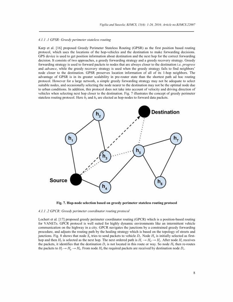
4.1.1 .1 GPSR: Greedy perimeter stateless routing Karp et al. [16] proposed Greedy Perimeter Stateless Routing (GPSR) as the first position based routing protocol, which uses the locations of the hop-vehicles and the destination to make forwarding decisions. GPS device is used to get position information about destination and the next hop for the correct forwarding decision. It consists of two approaches, a greedy forwarding strategy and a greedy recovery strategy. Greedy forwarding strategy is used to forward packets to nodes that are always closer to the destination i.e. progress and advance, while the greedy recovery strategy is used when the greedy strategy fails to find neighbors’ node closer to the destination. GPSR preserves location information of all of its 1-hop neighbors. The advantage of GPSR is in its greater scalability in pre-router state than the shortest path ad hoc routing protocol. However for a large network, a simple greedy forwarding strategy may not be adequate to select suitable nodes, and occasionally selecting the node nearer to the destination may not be the optimal node due to urban conditions. In addition, this protocol does not take into account of velocity and driving direction of vehicles when selecting next hop closer to the destination. Fig. 7 illustrates the concept of greedy perimeter stateless routing protocol. Here h3 and h4 are elected as hop-nodes to forward data packets.
Fig. 7. Hop-node selection based on greedy perimeter stateless routing protocol 4.1.1 .2 GPCR: Greedy perimeter coordinator routing protocol Lochert et al. [17] proposed greedy perimeter coordinator routing (GPCR) which is a position-based routing for VANETs. GPCR protocol is well suited for highly dynamic environments like an intermittent vehicle communication on the highway in a city. GPCR navigates the junctions by a constrained greedy forwarding procedure, and adjusts the routing path by the healing strategy which is based on the topology of streets and junctions. Fig. 8 shows that node Su tries to send packets to vehicle Dv. Node Ha is initially selected as first-hop and then Hb is selected as the next hop. The next ordered path is Hc → Hd → He. After node He receives the packets, it identifies that the destination Dv is not located in this route or way. So node Hb then re-routes the packets to Hf → Hg → Hh. From node Hh the required packets are received by destination node Dv.

Vigilia and Suseela; BJMCS, 13(4): 1-26, 2016; Article no.BJMCS.22007
9
Fig. 8. Routing technique and re-route establishment in GPCR
4.1.1 .3 GSR: Geographical source routing protocol The main goal of geographical source routing protocol (GSR) [18] is to overcome the problems of position-based routing methods designed for MANET when directly applied to VANETs in city scenarios. GSR combines position-based routing with geographical information, maintained by city maps to avoid the problem of stateless routing protocol. Static road map and location information are used in each node to find anchor points, along which packets should be forwarded to reach the destination. GSR computes a route to a destination by forwarding messages along different junctions. The advantage of GSR is that it is able to deal well with the dynamic network topology and high mobility at both city and highway scenarios. Forwarding packets are completely carried out on the basis of greedy forwarding strategy between two sequential junctions. The major weakness of GSR is the static junction selection mechanism where the source node computes sequence of junctions which the packet must navigate to reach to the destination. Dijkstra's algorithm is used to calculate the shortest path between the source and the destination based on a distance metric. Yet, the shortest path including junctions is not always the best path to the destination, since it does not deliberate vehicular traffic density on the roads. 4.1.1 .4 VADD: Vehicle-assisted data delivery routing protocol Zhao et al. [19] developed a protocol called Data delivery routing protocol (VADD). VADD protocol implemented the concept of carry-and-forward for data delivery from a mobile node to a static destination node. The important concern is to select an optimal forwarding path with the minimum packet delivery delay. To keep the low data transmission delay, VADD protocol transmits packets through wireless channels as much as possible. VADD protocol assumes that vehicles are furnished with pre-loaded maps, which provide the complete live-information such as traffic density and vehicle speed on roads at different times of

Vigilia and Suseela; BJMCS, 13(4): 1-26, 2016; Article no.BJMCS.22007
10
the day. Agreeing to the information provided by maps, VADD protocol proposed a delay model to estimate the data delivery delay in different roads as follows,
( ) ( )* *( ) ( )
( )
( )
*(1 )* *u v u vr ru v u v
u v
u v
E c Ed e e
r V
(6)
where d(u→v) is the total expected delay from source node Su and fixed destination Dv. The communication range of each vehicle is denoted as r. Traffic density between Su and Dv is represented as δ(u→v). Constant c is used to adjust packet forwarding delay. Euclidean distance between Su and Dv is denoted as E(u→v). Average vehicle velocity is denoted as V(u→v). Fig. 9 illustrates that source vehicle Su tries to forward a packet to static destination Dv. The possible junctions are J1, J2, J3 and J4. VADD considers J1, J2 and J3 as forwarded junctions to reach the destination Dv. J4 is rejected from the further selection process because of its high vehicle density.
Fig. 9. Identification of possible path in VADD 4.1.1 .5 Connectivity aware routing protocol Static destination is a major limitation in the previous method and it is changed in Connectivity-aware protocol (CAR). This method is proposed by Naumov et al. [20]. CAR protocol launches a routing path from source to destination by setting the anchor points at transitional junctions. CAR protocol initially directs the searching packets to find the destination. Each forwarding vehicle records its identification, hop count, and average number of neighbors in searching packets. Once the searching packets reach the destination node, the destination selects a routing path with the lowest delivery delay time and replies it to the source node.

Vigilia and Suseela; BJMCS, 13(4): 1-26, 2016; Article no.BJMCS.22007
11
While destination directs the reply packet to the source node, the junctions passed through by the reply packet are set as the anchor points. After the path established, data packets are forwarded in a greedy method through the anchor points. The concept of CAR protocol is shown in Fig. 10.
Fig. 10. Diagrammatic illustration of CAR protocol 4.1.1 .6 Reliable routing for roadside to vehicle communications Wan et al. [21] proposed a reliable routing protocol for the rural environment. Wan suggested two reliable routing strategies for roadside to vehicle (V2I) communication. The experiment of V2I communication in the rural environment is the territory factor. For example, a vehicle moving along the rural highway sometimes loses the line of sight (LOS) to the neighbor vehicle or to access points (APs) due to the obstacle-property produced by the curve roads and mountains. In addition, almost no reliable communication infrastructure is available in rural environment. One solution is APs can connect with multi-hop inter-vehicle communication. The lifetime of the network link is a very important issue for designing reliable routing. The link lifetime is forecasted by two conditions. Once the communication is established, the link lifetime breaks if (1) LOS between a pair of vehicles is lost, or (2) one vehicle moves out of the communication range of the neighboring vehicle. A communication link established in a shorter distance typically has longer lifetime and thus reliability increases. The link lifetime is used to predict the lifetime of the corresponding route. A route is fabricated by a series of links. The lifetime of a route is the least link lifetime in a route. Other than lifetime of a routing path in this protocol, the length-bounded maximum lifetime path is also considered. To build a length-bounded maximum lifetime path, reducing hops or intermittent nodes can increase the delivery delay-time. A routing path with fewer hops means that the links are established in the long distance. It is a direct proposition that establishes a longer routing path with longer lifetime and implies that the length of this routing path is also long. Fig. 11 (a) shows the example of lifetime-bounded shortest path. The green line is a lifetime bounded current routing path, where the minimum link lifetime is to be 3. We have shown

Vigilia and Suseela; BJMCS, 13(4): 1-26, 2016; Article no.BJMCS.22007
12
another candidate path route in red (Fig. 11 (b)). We assumed the threshold value is 13 and the connection that fulfils the threshold is shown in red. Fig. 11 (c) illustrates the example of minimum hop-count based maximum lifetime path. The blue line is the routing path with minimum number of hops to AP (hops = 5).
Fig. 11 (a). Lifetime bound shortest path based on reliable routing protocol
Fig. 11 (b). Threshold based reliable routing protocol
Fig. 11 (c). Minimum hop-count based maximum lifetime path in reliable routing protocol

Vigilia and Suseela; BJMCS, 13(4): 1-26, 2016; Article no.BJMCS.22007
13
4.1.2 Delay bounded routing protocols (D-Greedy and D-MinCost) in VANET Skordylis et al. [22] suggested a delay-bounded routing protocol in VANETs, which offers a delay bounded routing that fulfils user-defined delay requirements while at the same time preserves a low level of communication channel consumption. The delay-bounded routing protocol uses the concept of carry-and-forward schemes that try to deliver data from vehicles to an access point. He proposed two routing algorithms, Delay-bounded Greedy Forwarding (D-Greedy) and Delay-bounded Min-Cost Forwarding (D-MinCost) to calculate traffic information and the bounded delay-time to carefully opt between the data muling (A data mule is a special vehicle that carries a computer with storage between remote locations to efficiently create a data communication link) and multi-hop data forwarding strategies to decrease communication overhead while satisfying the delay restrictions enforced by the application. D-Greedy algorithm implements only local information about traffic to make an effective routing decision. D-Greedy algorithm picks the shortest path to an intended AP to form the map information, and then assigns the constrained delay-time to each street within the shortest path based on the length of different streets. In a best-case, if packets can be transported under the constrained delay-time in a street, Data Muling strategy is applied. Otherwise, multi-hop forwarding strategy is adopted if packets cannot be delivered within the constrained delay-time. D-MinCost algorithm deliberates global traffic information in a selected city to accomplish the minimum communication channel utilization within the constrained delay-time. According to the global traffic information, the cost and delay of each street can be forecasted. The cost denotes the total number of data transmissions in a selected street. The delay represents the time required to forward a data in a selected street. To achieve this, DSA (Delay Scaling Algorithm) is applied to select the best routing path with minimum channel utilization under the constrained delay-time.
4.2 Design challenges and future research directions in unicast protocols of VANET In this section, we have produced some design challenges of existing unicast routing protocols. Table 1 gives a detailed comparison of these selected protocols. Early forwarding decision gets more priority and it defines the routing decision of a protocol when there are data to be forwarded. Unfortunately delay bounded routing protocol is different from other unicast data delivery protocols, where carry-and-forward is the major routing decision to reserve the wireless communication channel. Destination location method illustrates how a protocol realizes the routing path and destination, which are categorized into two types, specific method and unified method. Specific method only indicates the location of destination and the protocol discovers routing path while the packet is forwarding. The unified method unifies the path discovery process into destination finding process. In unified method, the routing path and location of destination are concurrently discovered. Generally, the unified method has less routing setup time as well as rise of implementation complexity. All prevailing protocols adopt carry-and-forward method except delay-bounded routing protocol. Delay-bounded routing protocol implements multi-hop forwarding to reduce the packet delivery time if the expected packet delivery time cannot satisfy the user-defined delay. In this unicast routing protocols, most were established in urban areas under the theory of high network density. According to Yun-Wei Lin et al. [23], some future perspectives should consider the following:
A future work is based on the design of minimum delay unicast routing that may deal with low network density. The impression of intense density variability should be merged into the protocol design.
Another major challenge in protocol design in VANETs is about how to increase reliability of minimum delay unicast routing protocols to concurrently reduce packet delivery time and the number of packet losses.
Carry-and-forward approach deals mainly with packet delivery. So driver and his behavior should be monitored regularly for designing delay-bounded unicast routing protocols.
Scalability is also an important factor of routing protocol designing. The architecture of VANET could be large enough in cities so that it may have more number of unicast routing requests. It may create conflicts in routing requests when the network is working. The conflict of routing requests between vehicles should take into attention, especially in the intersection point or junction.

Vigilia and Suseela; BJMCS, 13(4): 1-26, 2016; Article no.BJMCS.22007
14
Another key research is promising minimum delay in vehicle-to-vehicle communication. This is important to transport emergency messages between the vehicles. This idea may be extended to both sparse and dense traffic conditions.
4.3 Multicast routing protocols Multicast and geocast routing are the most opted routing techniques in VANETs. One of the design challenges is how to develop the efficient multicast/geocast protocol over VANETs with the highly dynamic network topology. According to the property of geographic region, existing results can be classified into simple multicast/geocast protocol and spatiotemporary multicast/geocast routing protocols. Simple multicast/geocast concentrates on set of defined vehicles and spatiotemporary multicast/geocast balances between both time and space complexity in data delivery. The detailed discussion is as follows. 4.3.1 IVG: Multicast protocol in ad hoc networks inter-vehicle geocast Bachir et al. [24] proposed an ad hoc networks inter-vehicle geocast, called IVG protocol. It follows the concept of simple multicast/geocast and the primary concern of an IVG protocol is to notify all the vehicles on the way if any danger occurs. The danger area is determined in terms of driving direction and current positioning of vehicles. Vehicles located in the danger area form a cluster called multicast group. This group is formulated temporarily based on the location, speed, and driving direction of vehicles. IVG protocol broadcasts periodic beacons to overcome temporary network fragmentation which is used in distributed robust geocast multicast protocol for delivering messages to a set of members in a group. The re-broadcast period is considered based on the maximum vehicle speed. Also, IVG protocol reduces the total number of hops to deliver a message by using the accepting time. A vehicle which has the farthest distance to source vehicle waits for minimal accepting time to re-broadcast. Fig. 12 illustrates the concept of danger area that is used in IVG protocol.
Fig. 12. Danger area fragmentation (marked red) based on IVG protocol

Vigilia and Suseela; BJMCS, 13(4): 1-26, 2016; Article no.BJMCS.22007
15
Table 1. Comparison of unicast protocols
Protocols GPSR GPCR GSR VADD CAR Reliable routing Delay bounded
Early forwarding decision
1-hop communication
Multihop communication
Multihop communication
Multihop communication
Multihop communication
Multihop communication
Carry-and-forward
Destination location method
Specific method Specific method Specific method Specific method Unified method Unified method Specific method
Map needed for data transmission
No No Yes Yes Yes No No
Rural / Urban Urban Urban Urban Urban Urban Rural Urban

Vigilia and Suseela; BJMCS, 13(4): 1-26, 2016; Article no.BJMCS.22007
16
4.3.2 DRG: Distributed robust geocast multicast routing protocol Joshi et al. [25] proposed an efficient protocol that follows spatiotemporary multicast/geocast strategy for inter-vehicle communication. The goal of multicast routing protocol is to deliver data packets to vehicles that are located in a specified static region. The imposed condition is that, a vehicle should take packets if it is present in an intended geographic location. Otherwise the vehicle drops packets. The zone of relevance (ZOR) and zone of forwarding (ZOF) are the two independent geographic regions specified by this protocol. ZOR is a geographic region which identifies vehicles based on region of relevance for receiving the packets. ZOF is another geographical region which identifies vehicles based on region and can only forward the received packets to other vehicles located in ZOR. It is worthy to listen that, ZOF usually surrounds ZOR to ensure an effective communication between inter-vehicles. Fig. 13 shows that the temporary network fragmentation (ZOR and ZOF) happens in distributed robust geocast and multicast routing protocol.
Fig. 13. Network fragmentation of roads based on distributed robust geocast multicast protocol 4.3.3 DBMR: Distant node based multicast routing protocol
Dibakar Chakraborty [26] proposed spatiotemporary multicast/geocast routing for VANETs called distant node based multicast routing protocol which contains a threshold τ to select the nodes for receiving the multicast data packet. DBMR protocol splits the whole task into three distinct phases namely, neighbor-list collection, multicast group selection and distant node selection. The updated one-hop neighbor collection is the duty of the neighbor-list collection phase. A set of neighbor-list is collected by repeating the neighbor-list collection process again and again. The neighbor nodes share this list later for selection of distant nodes. In a sparse environment, the neighbor-list collection is a critical process and needs to be updated frequently. This can be done by using periodic “hello” signals. After the list is ready, threshold τ is used to select multicast group. A threshold τ becomes a major concern to classify the updated one-hop neighbors for receiving the multicast data packet with respect to the current forwarding node. The multicast packet receiving nodes are selected on the basis of packet transmission time. The “hello” messages comprise the timestamp before it has been sent out to other nodes. The current forwarding node receives “hello” messages from its updated one hop neighbors and calculates the transmission time and averages two recent consecutive transmission times of all the one-hop neighbors and then compares with a threshold τ for selection of data packet receiving neighbors. For an example, if node n is added to the multicast group of updated forwarding node F, the following condition is satisfied.
Tn(i+1) + TF(i) ≥ 2τ , for all n in the one-hop Neighbor-List of F (7)
where, Tn(i) is the computed transmission time for node n at the ith time instant.

Vigilia and Suseela; BJMCS, 13(4): 1-26, 2016; Article no.BJMCS.22007
17
The distant node is selected based on several conditions. If the multicast group is empty (Fig. 14 (a)), then the source node doesn’t forward it rather buffers the packet in message table and carries the data packet. On the other hand if there is only one member in the multicast group then it will be automatically selected as a distant node. It is shown in Fig. 14 (b). At last, if multiple group (refer Fig. 14(c)) exists after receiving the multicast data packet, each and every node of the multicast group pledges two timers namely Ti and Tj. The timer Ti is used to forecast the time instance of when the distant node selection procedure will start, after the multicast data packets are received completely by the nodes. The timer Tj is used to select the re-multicast time. The Ti timer is same for all the nodes on a group. Once Tj terminates the distant node selection procedure starts. The multicast group selection is illustrated in Fig. 14 and the detailed view is shown in Table 2.
Fig. 14. Illustration of various road conditions while selecting a multicasting group in DBMR
Fig. 15. Distant node selection based on DBMR protocol

Vigilia and Suseela; BJMCS, 13(4): 1-26, 2016; Article no.BJMCS.22007
18
Table 2. Multicast group selection in DBMR
Node Updated neighbor-list
Multicast group
Common nodes
Count of common nodes
Required action after Ti expires
Required action after Tj expires
S {h1, h2, h4, h6} {h1, h4} {h1, h4} #3 Not applicable Not applicable
h1 {S, h2, h3} - {h2} #1 Re-multicast Distant node h4 {S, h2, h5} - {h2} #1 Re-multicast Distant node
The DBMR protocol excellently chooses the multicast group by using threshold τ. It effectively reduces the flooding problem and is applicable for sparse connected VANETs. The major weakness is periodic “hello” signals that are required for stable connection between vehicle nodes.
4.4 Design challenges and future research directions in multicast protocols of VANET
Each of the protocols discussed above in this review has its strong point and the complete systematic comparison is shown in Table 3. Prevailing protocols consider the static multicast/geocast region except distributed robust geocast multicast routing protocol. Spatiotemporal property expresses that both the time and location of a vehicle are the major deciding factors whether the vehicle needs to receive packet or not. Existing protocols examine the single source multicast and geocast routing. However, it is important to consider the multi-source multicast and geocast routing issues. According to Yun-Wei Lin et al. some future perspectives should consider the following:
The multi-source multicast and geocast routing are worth to develop since the higher end-to-end applications may require it.
Reliability should be reflected to design the multicast and geocast protocols. The multicast/geocast message used in a protocol should be delivered with high successful rate.
Multicast and geocast routing for delay supported applications are also considered. Delay supported messages usually accept delay, where network bandwidth is generally kept for emergency messages. It is worth to develop an efficient multicast/geocast routing protocol for delay supported applications with delay-constraint and delay-tolerant capabilities with low bandwidth utilization.
Multicast and geocast routing protocols may be extended to the rural environments, where traffic is not so dense nor so sparse.
The protocol design of multicast and geocast routing should consider scalability. VANET in an urban environment is a possibly large-scale network. Therefore, future works can be concentrated on developing a multi-source multicast and geocast routing protocol which cares applications of multiple multicast and geocast sources in a VANET. In the next section, broadcast routing protocol is considered.
Table 3. Comparison of multicast protocols
Protocols IVG DRG DBMR Early forwarding decision
Multihop communication
Multihop communication
Hybrid (1-hop or Multihop) communication
Destination location method
Specific method Specific method Specific method
Map needed for data transmission
No No No
Spatial relevant Yes Yes Yes Spatiotemporary No Yes Yes Mobility of destination No No Yes Rural / Urban Urban Urban Urban

Vigilia and Suseela; BJMCS, 13(4): 1-26, 2016; Article no.BJMCS.22007
19
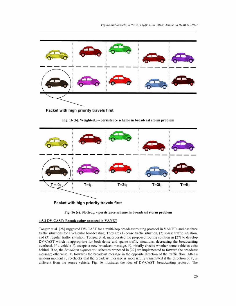
4.5 Broadcast routing protocols Broadcast is an important and last type of routing for a vehicle to disseminate a broadcast message to all the others in a VANET. This section reviews the existing broadcast routing protocols in VANETs. 4.5.1 Broadcast storm problem in ad hoc wireless networks Broadcasting protocol uses many-to-many radio communication and thus creates broadcast storm problem. Tonguz et al. [27] shows that the broadcast storm problem causes serious packet collision and packet loss in a VANET. Tonguz et al. [27] proposed three different broadcast defeat techniques, weighted p-persistence, slotted 1- persistence, and slotted p-persistence. These three techniques follow broadcast suppression method to reduce the total number of control messages. As per weighted p-persistence scheme, if vehicle Vy gets a packet from vehicle Vx, vehicle Vy first checks whether the same packet has been already received. If vehicle Vy gets this packet at the first time, then vehicle Vy has probability Pxy to re-broadcast the received
packet. Otherwise, vehicle Vy drops this packet, with the probability Pxy =xyD
R
, where Dxy is the distance
between vehicle Vx and Vy, R is the transmission range. Neighbors of vehicle Vx change the probability value Pxy to 1 to confirm that the message must be broadcasted if they have not received the re-broadcast message after waiting a random time t. In the slotted 1-persistence scheme, if vehicle Vy initially receives the packet from vehicle Vx, then vehicle Vy delays for TSxy time slots, vehicle Vy, has probability to change Pxy to 1 to re-broadcast the packet, where TSxy = Sxy × τ, where τ is the broadcast time for one hop transmission and Sxy =
(1 )xy
ts
DN
R
or (1 )xy
ts
DN
R
, if Dxy ≤ R; otherwise Sxy = 0, where Nts is the default number time-
slots. The slotted p-persistence scheme is the mixture of the weighted p-persistence and slotted 1-persistence scheme. If vehicle Vy initially receives the packet from Vx, then vehicle Vy delays for TSxy time-slots. Vehicle Vy, has probability value Pxy to re-broadcast the same packet. Fig. 16 gives the example of these three different broadcast schemes.
Fig. 16 (a). Slotted 1- persistence scheme in broadcast storm problem
Vigilia and Suseela; BJMCS, 13(4): 1-26, 2016; Article no.BJMCS.22007
20
Fig. 16 (b). Weighted p - persistence scheme in broadcast storm problem
Fig. 16 (c). Slotted p - persistence scheme in broadcast storm problem
4.5.2 DV-CAST: Broadcasting protocol in VANET
Tonguz et al. [28] suggested DV-CAST for a multi-hop broadcast routing protocol in VANETs and has three traffic situations for a vehicular broadcasting. They are (1) dense traffic situation, (2) sparse traffic situation, and (3) regular traffic situation. Tonguz et al. incorporated the proposed routing solution in [27] to develop DV-CAST which is appropriate for both dense and sparse traffic situations, decreasing the broadcasting overhead. If a vehicle Vy accepts a new broadcast message, Vy initially checks whether some vehicles exist behind. If so, the broadcast suppression schemes proposed in [27] are implemented to forward the broadcast message; otherwise, Vy forwards the broadcast message in the opposite direction of the traffic flow. After a random moment Vy re-checks that the broadcast message is successfully transmitted if the direction of Vy is different from the source vehicle. Fig. 16 illustrates the idea of DV-CAST: broadcasting protocol. The

Vigilia and Suseela; BJMCS, 13(4): 1-26, 2016; Article no.BJMCS.22007
21
source vehicle Vs initiated a message and forwards from group A to group C. Although groups A, B, and C are dense, group A and C couldn’t connect directly and encounter the temporary network fragmentation problem. Group A cannot directly forward packets to group C. In this case, vehicle Vx can forward packets to group B which is in the opposite direction, then vehicle Vy forwards packets to group C. Note that, the temporary network fragmentation problem is resolved in this DV-CAST: broadcast protocol. The diagrammatic illustration is shown in Fig. 17.
Fig. 17. Group A is indirectly broadcasted a message to group C by using group B
4.5.3 A border node based routing protocol for partially connected vehicular Ad Hoc networks
Mingliu Zhang et al. [29] offered a hybrid methodology called Border node Based Routing (BBR) for partially connected sparse VANET groups. It uses domain function where location and mobility information is not available. The BBR protocol can bear network partition due to low node density and high node mobility. The main idea of BBR protocol is epidemic routing, but it reduces flooding of packets by introducing two individual functional units: A neighbor discovery algorithm, and a border node selection algorithm. The BBR neighbor discovery algorithm is the same as neighbor discovery protocol (NDP) suggested in the Zone Routing Protocol (ZRP) [30]. Periodic beacon messages are used to advertise the existence of source nodes. The benefit of using a network layer based NDP is that, all routing functions are accomplished in the network layer, without thoughtfulness of the specific MAC layer technology used. In the BBR protocol, border nodes are selected based on broadcast messages. A border node is a node which has the duty of saving received broadcast messages and forwarding the messages when applicable. For a set of nodes that receives the same broadcast message, only those nodes selected as border nodes will retain the received message and rebroadcast it later when those nodes meet new neighbor nodes. The BBR protocol adopts a distributed border node selection algorithm. The choice of whether a node is a border node or not is made discretely by an individual node based on its one-hop neighbor information and the received broadcast information. Border node selection based on least common neighbors uses the idea that nodes at the edge of

Vigilia and Suseela; BJMCS, 13(4): 1-26, 2016; Article no.BJMCS.22007
22
transmission range should have less common neighbor nodes with the broadcast source node, when compared to those nodes that are nearer to the source node.
Fig. 18. A typical node broadcast process in BBR protocol
As specified in Fig. 18, a circle delimits the radio transmission range (R) of the node located at the center of the circle. For example, assume node S as a broadcast source or a source node. Nodes at the edge of the radio transmission range such as node P and C when compared to nodes adjacent to the broadcast source node such as node A, B and D have less common neighbors with node S. Selection of nodes such as P or C or both as the border nodes for further broadcast is appropriate that this selection results in maximum range and speedy information propagation while saving bandwidth by reducing unnecessary rebroadcasts. Hop nodes are selected by predefined rules and BBR algorithm says that every node has three tables or buffer memory: A neighbor table, a border node selection table and a forward table. The neighbor table is used to store the recent one hop neighbor node information. The border node selection table is used for border node selection process. The third one is a forward table for buffering data packets required for future forwarding. A source node that creates a data packet is selected as a border node. A node that broadcasts or rebroadcasts a data packet will use a specific field called “common neighbor #” which has a list of its current neighbors attached. The “common neighbor #” field is set to be the number of the common neighbors between the current node and the previous node that broadcasts the data packet. If a node is a source node, then the “common neighbor #” field is set to zero. Each packet has its unique packet ID, made by the originating node. The packet ID remains the same as packets move from source to destination. Predefined rules of BBR algorithm can be discussed in three different cases. First case is that, when a source node has a packet to forward and there is no available neighbor, it saves the packet in the forward table and broadcasts it later when there are neighbors in its range R. If a source node has one node in the neighbor list then no border node selection will be carried out and it is a border node which is the second case. Third case is that, if the source node has more than one neighbor nodes within its radio transmission range, then the neighbor nodes

Vigilia and Suseela; BJMCS, 13(4): 1-26, 2016; Article no.BJMCS.22007
23
initiate two timers, an access delay timer Tdelay and a maximum delay timer Tmax. The timer Tdelay is used to choose when a node wants to rebroadcast the packet if it has to do so. The timer Tmax is used to choose when a node should initiate the border node selection process. The value of Tdelay and Tmax can be calculated as follows.
Tdelay = (i-1)*∆t (8)
Tmax = a*n*∆t (9)
where i is the position of the neighbor node on the neighbor list. The variable n is the total number of neighbors on the neighbor list. The parameter ∆t is the probable transmission delay for sending one packet, which can be estimated by length of packet / data transmission speed. The parameter a (a ≥1) is used to increase the timer value to make sure that a node receives all the rebroadcast packets that might be coming from the neighbors of the former forwarding node. During Tmax, each node in the group chooses either to rebroadcast or not when it’s Tdelay expires. The final decision is prepared depending on whether all its recent one hop neighbors received the broadcast packet information or not. During the entire Tmax interval, each node will listen the radio communication continuously. Rebroadcast packets from its neighbors will also be saved provisionally for the use of the border node selection procedure. When Tmax terminates, a node checks whether it is the node with the least common neighbor number with the previous broadcast source based on all packets received and recorded in its border node selection table. If it is, it will select itself as a border node. Otherwise it is not a border node. As a node can only collect packets from the source node and from its common neighbors that correspond to a source node, the least common neighbor comparison is carried out between itself and its common neighbors with the source node.
4.6 Design challenges and future research directions in broadcast protocols of VANET
The surveyed protocols explore how to provide an efficient broadcast routing technique. Each of the protocols listed above in this survey has its advantage point and the detailed critical comparison is shown in Table 4. Prevailing broadcast routing protocols are used for safety applications to transmit emergency messages; however, there are still some comfort applications which need an efficient broadcast routing protocol, such as public information, advertisements and navigation information. According to Yun-Wei Lin et al. the future works should consider the following:
An imaginable future work is how to design an efficient broadcast routing protocol for comfort applications with delay-constraint and delay-tolerant capabilities and low bandwidth utilization. Comfort messages are usually not so urgent, so it can be distributed under a constrained delay time. Also, bandwidth must be reserved for urgent and safety applications, so an efficient broadcast routing protocol for comfort applications should preserve low bandwidth consumption.
Broadcast routing protocols for comfort applications should be able to integrate multiple partial comfort messages into a single and complete message since mass information cannot be fully delivered at once under low bandwidth consumption.
A main challenge in broadcast protocol design is how to cultivate reliable broadcast routing protocols for comfort applications to ensure that broadcast messages are successfully distributed to all the other vehicles in a VANET.
The broadcast message should be able to be distributed under low network density or sparse networking conditions. The network density is usually minimum in off-peak hour; however, the broadcast message is still unavoidably distributed to all vehicles in a network. Hence, the idea of how to design a consistent broadcast routing protocol for comfort applications with a delay-tolerant ability and low bandwidth consumption will possibly be the future works in VANETs.
Reliability and scalability are another major issues and need more attention while designing a broadcast routing protocol.

Vigilia and Suseela; BJMCS, 13(4): 1-26, 2016; Article no.BJMCS.22007
24
Table 4. Comparison of broadcast protocols
Protocols Broadcast storm DV-CAST BBR Early forwarding decision
Broadcast communication
Broadcast communication
Hybrid (1-hop or Multihop) communication
Fragmentation solution Probability based re-broadcast
Reverse traffic flow Least common neighbor based re-broadcast
Map needed for data transmission
No No No
Spatial relevant Yes Yes Yes Mobility of destination Yes Yes Yes Rural / Urban Urban Urban Urban
5 Conclusion Unicast, multicast, and broadcast routing protocols are key concerns in the network layer for VANETs. This work surveys current unicast, multicast, and broadcast protocols for VANETs. The unicast routing protocols are divided into minimum-delay and delay-bound approaches. The minimum-delay unicast routing protocols build a minimum-delay routing path as soon as possible. The delay-bound routing protocol consumes the carry-and-forward technique to diminish the channel utilization within a constrained delay time. This work also reviews important multicast and geocast protocols for VANETs. The multicast in VANETs is defined by distributing multicast packets from a mobile vehicle to all multicast-member vehicles. The geocast in VANETs is defined by distributing geocast packets from a source vehicle to vehicles (V2V communication) located in a specific geographic region. Finally, broadcast protocols in VANETs are also presented. We estimate the tendency of the design of routing protocols for VANETs with low communication overhead, low delivery delay, and high adjustability for both rural and urban environments.
Competing Interests Authors have declared that no competing interests exist.
References [1] Rajini Girinath D, Selvan S. Vehicular ad-hoc network routing protocols in realistic situations. IEEE
International Conference on Control, Automation, Communication and Energy Conservation, Perundurai, India. 2009;1–6.
[2] Khabazian M, Ali MKM. A performance modeling of connectivity in vehicular ad-hoc networks.
IEEE Transactions on Vehicular Technology. 2008;57(4):2440–2450,
[3] Foh CH, Liu G, Lee BS, Seet BC, Wong KJ, Fu CP. Network connectivity of one-dimensional MANETs with random waypoint movement. IEEE Communications Letters. 2005;9(1):31–33.
[4] Huang XX, Fang Y. Performance study of node-disjoint multipath routing in vehicular ad-hoc networks. IEEE Transactions on Vehicular Technology. 2009;58(4):1942–1950.
[5] He R, Rutagemwa H, Shen X. Differentiated reliable routing in hybrid vehicular Ad-hoc networks. IEEE International Conference on Communications, Beijing. 2008;2353–2358.
[6] Pham PP, Perreau S. Performance analysis of reactive shortest path and multipath routing mechanism with load balance. Twenty-Second Annual Joint Conference of the IEEE Computer and Communications. 2003;251–259.

Vigilia and Suseela; BJMCS, 13(4): 1-26, 2016; Article no.BJMCS.22007
25
[7] Kosch T, Schroth G, Strassberger M, Bachler M. Automotive internetworking. John Wiley, New York; 2012.
[8] Wenshuang Liang, Zhuorong Li, Hongyang Zhang, Shenling Wang, Rongfang Bie. Vehicular Ad hoc networks: Architectures, research issues, methodologies, challenges and trends. International Journal of Distributed Sensor Networks; 2015. Available:http://dx.doi.org/10.1155/2015/745303
[9] Andreas Festag, Alban Hessler, Roberto Baldessari, Long Le, Wenhui Zhang, Dirk Westhoff. Vehicle-to-vehicle and road side sensor communication for enhanced road safety. Proceedings of ITS World congress and Exhibition, New York, USA; 2008.
[10] Miad Faezipour, Mehrdad Nourani, Adnan Saeed, Sateesh Addepalli. Progress and challenges in intelligent vehicle area networks. Communications of the ACM. 2012;55(2):90–100.
[11] Available:https://en.wikipedia.org/wiki/OSI_model
[12] Hartenstein H, Laberteaux K. VANET – Vehicular applications and inter-networking technologies. John Wiley, New York; 2010.
[13] Maier MW, Emery D, Hilliard R. ANSI/IEEE 1471 and systems engineering. Systems Engineering: The Journal of the International Council on Systems Engineering. 2004;7(3):257–270.
[14] Voss F, Gloaguen C, Fleischer F, Schmidt V. Distributional properties of euclidean distances in wireless networks involving road systems. IEEE Journal of Selected Areas in Communications. 2009;27(7):1047–1055.
[15] Souid I, Ben Chikha H, Attia R. Blind spectrum sensing in cognitive vehicular ad hoc networks over Nakagami-m fading channels. IEEE International Conference on Electrical Sciences and Technologies in Maghreb. 2014;1–5.
[16] Karp B, Kung HT. GPSR: Greedy perimeter stateless routing for wireless networks. Sixth Annual ACM/IEEE International Conference on Mobile Computing and Networking Boston. 2000;243–254.
[17] Lochert C, Mauve M, Fera H, Hartenstein H. Geographic routing in city scenarios. ACM SIGMOBILE Mobile Computing and Communications Review. 2005;9(1):69–72.
[18] Lichuan L, Wang Z, Jehng WK. A geographic source routing protocol for traffic sensing in urban environment. IEEE International Conference on Automation Science and Engineering, Arlington. 2008;347–352.
[19] Zhao J, Cao G. VADD: Vehicle-assisted data delivery in vehicular ad hoc networks. IEEE Transactions on Vehicular Technology. 2008;1910–1922.
[20] Naumov V, Gross T. Connectivity-aware routing (CAR) in vehicular ad hoc networks. IEEE International Conference on Computer Communications, Anchorage. 2007;1919–1927.
[21] Wan S, Tang J, Wolff RS. Reliable routing for roadside to vehicle communications in rural areas. IEEE International Conference on Communications, Beijing. 2008;3017–3021.
[22] Skordylis A, Trigoni N. Delay-bounded routing in vehicular ad-hoc networks. ACM International Symposium on Mobile Ad hoc Networking and Computing, New York. 2008;341–350.

Vigilia and Suseela; BJMCS, 13(4): 1-26, 2016; Article no.BJMCS.22007
26
[23] Yun-Wei Lin, Yuh-Shyan Chen, Sing-Ling Lee. Routing protocols in vehicular Ad hoc networks: A survey and future perspectives. Journal of Information Science and Engineering. 2010;26:913–932.
[24] Bachir A, Benslimane A. A multicast protocol in ad hoc networks inter-vehicle geocast. IEEE Semiannual Conference on Vehicular Technology. 2003;2456–2460.
[25] Joshi HP, Sichitiu M, Kihl M. Distributed robust geocast multicast routing for inter-vehicle communication. Proceedings of WEIRD Workshop on WiMax, Wireless and Mobility. 2007;9–21.
[26] Dibakar Chakraborty. Distant node based multicast routing protocol. IOSR Journal of Computer Engineering. 2012;2(3):49–55.
[27] Tonguz OK, Wisitpongphan N, Parikh JS, Bai F, Mudalige P, Sadekar VK. On the broadcast storm problem in ad hoc wireless networks. IEEE International Conference on Broadband Communications, Networks and Systems. 2006;1–11.
[28] Tonguz OK, Wisitpongphan N, Bai F, Mudalige P, Sadekar V. Broadcasting in VANET. IEEE International Conference on Mobile Networking for Vehicular Environments. 2007;7-12.
[29] Zhang M, Wolff RS. A border node based routing protocol for partially connected vehicular Ad hoc Networks. Journal of Communications. 2010;5(2):130–143.
[30] Charles E. Perkins. Ad Hoc networking. Addison-Wesley; 2001. _______________________________________________________________________________________ © 2016 Vigilia and Suseela; This is an Open Access article distributed under the terms of the Creative Commons Attribution License (http://creativecommons.org/licenses/by/4.0), which permits unrestricted use, distribution, and reproduction in any medium, provided the original work is properly cited. Peer-review history:
The peer review history for this paper can be accessed here (Please copy paste the total link in your browser address bar) http://sciencedomain.org/review-history/12705