
SURVEY ON SEAPLANE HYDRO-SKI DESIGN TECHNOLOGY
124
r r i i i i r r i r i i i ] i I 05 o to Report 7489-1 (Unclassified) SURVEY ON SEAPLANE HYDRO-SKI DESIGN TECHNOLOGY PHASE 1: QUALITATIVE STUDY by P. A. Pepper and L. Kaplan Edo Corporation T APREgt {i M Distribution of This Document is Unlimited Performed for the OFFICE OF NAVAL RESEARCH aid the NAVAL AIR SYSTEMS COMMAND DEPARTMENT OF THE NAVY WASHINGTON, D. C. , under Contract N00014-66-C0126 m$ (»
Transcript of SURVEY ON SEAPLANE HYDRO-SKI DESIGN TECHNOLOGY

r r i i i i r
r i
r i i i ]
i
I
05
o to
Report 7489-1 (Unclassified)
SURVEY ON SEAPLANE HYDRO-SKI DESIGN TECHNOLOGY
PHASE 1: QUALITATIVE STUDY
by P. A. Pepper and L. Kaplan
Edo Corporation
T APREgt ■ {i
M
Distribution of This Document is Unlimited
Performed for the
OFFICE OF NAVAL RESEARCH aid the NAVAL AIR SYSTEMS COMMAND DEPARTMENT OF THE NAVY WASHINGTON, D. C. , under Contract N00014-66-C0126
m$ (»

!
-
V/SÄ
Report No. 7489-1 (Unclassified)
SURVEY ON SEAPLANE
HYDRO-SKI DESIGN TECHNOLOGY
PHASE 1: QUALITATIVE STUDY
by P. A. Pepper and L. Kaplan
Edo Corporation
23 December 1966
Distribution of This Document is Unlimited
Performed for the
OFFICE OF NAVAL RESEARCH and the NAVAL AIR SYSTEMS COMMAND DEPARTMENT OF THE NAVY WASHINGTON, D. C. . under Contract N00014-66-C0126
■
'* t > -

■*r
r Report 7489-1
YOÄ TABLE OF CONTENTS
I
I
Section Title Pa^e
ABSTRACT vii
1 INTRODUCTION . 1-1
2 HISTORICAL REVIEW OF HYDRO-SKi TECHNOLOGY 2-1
3 PRINCIPLES OF HYDRO-SKI APPLICATION 3-1
4 HYDRO-SKI CONFIGURATION CHARACTERISTICS 4-1
4.1 General 4-1 4.2 Hydro-Ski Characteristics 4-2
4. 2,1 Main Planing Characteristics 4-2 4. 2. 2 Beam Loading 4-2 4.2.3 Lenglh-Beam Ratio 4-3 4.2.4 Deadrise 4-4 4. 2. 5 Planform 4-5 4. 2. 6 Longitudinal Curvature 4-6 4. 2. 7 Hydro-Ski Cross-Section 4-6 4. 2. 8 Auxiliary Features , 4-6
4. 2. 8.1 Slotted Nose 4-7 4. 2. 8. 2 Drooped Nose 4-7 4. 2. 8. 3 Spray Strips 4-7 4.2. 8.4 Trailing Edge Flaps 4-8 4. 2, 8. 5 Variable Area 4-8 4. 2. 8. 6 Integral Beaching Gear 4-9
4. 3 Hydro-Ski Installation Characteristics 4-10 4. 3.1 Basic Installation Geometry 4-10
4. 3. 1.1 Ski Location 4-10 4.3.1.2 Hydro-Ski Incidence 4-10
4. 3. 2 Strut Characteristics 4-11 4.3.2.1 Strut Location Relative to Ski . 4-11 4.3.2.2 Strut Length 4-11 4.3.2.3 Strut Section 4-12
4. 3. 3 Shock Strut Mountings 4-13 4.3.4 Multiple Ski Configurations 4-14 4.3.5 Retraction System 4-15
4.4 Design Loading Criteria , . , 4-17 4.4.1 Hydro-Ski Load Criteria 4-17 4.4.2 Strut Load Criteria , 4-18 4.4.3 Hull Load Criteria 4-18
4.5 Hydro-Ski Installation Weight Data 4-18
ii
«mfmamtaPtl
> »>.
i

I I
I !
V/tA Report 7489-1
Section
TABLE OF CONTENTS (cont.)
Title
HYDRO-SKI SEAPLANE HYDRODYNAMIC CHARACTERISTICS
5.1 Towing Tank Model - Prototype Correlation 5.1.1 Towing Tank Model vs. Prototype Aircraft ....
5.1.1.1 Froude Scale Relations 5.1.1. 2 Degrees of Freedom 5.1.1. 3 Aerodynamic Characteristics . 5.1.1, 4 Local Airflow Effects 5.1.1. 5 Scale Effects 5.1.1.6 Spray Patterns 5.1.1. 7 Load Factors 5.1.1. 8 Structural Flexibility
5.1.2 Model vs Prototype Operational Environment . . . 5.1.2.1 Waves 5.1.2.2 Winds
5.1. 3 Pilot Control 5.2 Hydro-Sid Seaplane Resistance Characteristics
5. 2.1 Pre-unporting Resistance 5. 2. 2 Post-unporting Resistance 5. 2. 3 Rough Water Resistance 5. 2. 4 Hydro-Ski Resistance
5, 2. 4,1 Hydro-Sid Submerged and Fully Wetted . . 5. 2. 4. 2 Hydro-Ski Submerged and Ventilated . . . 5. 2. 4, 3 Hydro-Ski Planing
5. 2. 5 Strut Resistance 5. 2. 5.1 Strut Section Fully Wetted 5. 2. 5. 2 Strut Section Ventilated 5. 2, 5, 3 Interference Effects
5.2,6 Hull Resistance 5. 2. 7 Spray Resistance
5. 2. 7.1 Basic Spray Drag 5. 2. 7. 2 Spray Impingement Drag . . -
5. 3 Maximum Hydro-Ski Impact Loads 5. 3.1 Maximum Impact Load Formula 5. 3. 2 Bow Submergence 5. 3. 3 Stern Taper 5. 3. 4 Shock Absorbers 5. 3. 5 Yaw and Roll 5. 3. 6 Waves 5. 3. 7 Wing Lift
Page
5-1
5-1 5-1 5-1 5-2 5-3 5-4 5-4 5-5 5-6 5-7 5-7 5-7 5-8 5-9 5-10 5-1U 5-11 5-11 5-12 3-12 5-12 5-13 5-13 5-13 3-13 3-14 5-14 5-15 5-15 5-16 5-16 5-16 5-18 5-18 5-19
■20 ■21
ui
"•:
i ■•■^■■■^i:. ■ -■■• ■■ /

1
•
r
r
i i r i (
i i
■,
Section
YMA Rejwrt 7489-1
TABLE OF CONTENTS (cont.)
Title Page
5.4 Hydro-Sid Pressure Distribution '^-21 5. 4,1 Submerged Hydro-Skis 3-21 5, 4. 2 Surfaced Hydro-Skis .'>-22 5. 4. 3 Impact - Planing Relation •")-22
5.5 Unsymmetrical Loadings 0-24 5. 5.1 Unsymmetrical Hydro-Ski Loadings 5-24
5. 5* 1.1 Hvdro-Ski Submerged ...,,,...,.... 5-24 5. 5.1. 2 Hydro-Ski Planing 5-24
5. 5. 2 Unsymmetrical Strut Loads 5-24 5. 5. 2.1 Fully Wetted Strut 5-25 5. 5. 2. 2 Ventilated Strut 5-25
5.6 Hull Impact Loads 5-25 5.6.1 Effects of Hydro-Ski Installation 5-25 5.6.2 Take-off in Smooth Water and Waves 5-26 5. 6. 3 Landing in Smooth Water and Waves 5-27 5.6.4 Hull Loading Criteria 5-27
HYDRO-SKI SEAPLANE PERFORMANCE CHARACTERISTICS 6-1
6.1 Unporting Speed 6-1 6.2 Unporting/Take-Off Speed Ratio 6-1 6.3 Unporting Trim 6-2 6.4 Unporting Spray 6-2 6, 5 Resistance 6-2
6. 5. 1 Smooth Water 6-2 6. 5. 2 Rough Water 6-3
6.6 Take-Off Timv 6-3 6.6.1 Smooth Water , 6-3 6.6.2 Rough Water 6-3
6.7 Ski-Strut Vibrations 6-3 6. 7, 1 Wave Impact Response 6-4 6,7.2 Hydroe'astic Effects 6-4
6.8 High Speed Taxiing 6-5
HYDRO-SKI SEAPLANE STABILITY AND CONTROL CHARACTERISTICS 7-1
7.1 Longitudinal 7-1 7. 1. 1 Pre-unporting Regime 7-1 7.1.2 Unporting 7-1 7. 1. 3 Post - Unporting 7-4
i 1 IV

'* -
4- Report 7489-1
VS/A
TABLE OF CONTENTS (eont.)
Section Title Page
7.1. 3.1 Low - Angle Porpoising 7-4 7.1. 3.2 High - Angle Porpoising 7-5
7.1, 4 Touciidown 7-6 7.1. 5 Ski Submergence 7-6
7.2 Directional 7-6 7.2.1 Pre-unporting Regime 7-7 7.2.2 ünporting, Post-unporting and Touchdown 7-7 7. 2. 3 Ski Submergence 7-8
7.3 Lateral 7-8 7. 3.1 Pre-unporting Regime 7-8 7.3.2 Ünporting 7-9 7. 3. 3 Post-unporting and Touchdown 7-9 7. 3. 4 Sid Submergence 7-10
8 BIBLIOGRAPHY OF HYDRO-SKI TECHNOLOGY 8-1
APPENDIX A INTERVIEWS WITH SELECTED HYDRO-SKI SPECIALISTS
DISTRIBUTION LIST
7~

i
i I I f f i f
c I I r
i i i
Figure
2-1
2-2
2-3
2-4
2-5
2-6
2-7
2-8
2-9
2-10
2-11
2-12
2-13
2-14
2-15
- i~—
'-**!<**- --^rez*?,.. .. '4-,, .
Report 7489-1
LIST OF FIGURES
Page
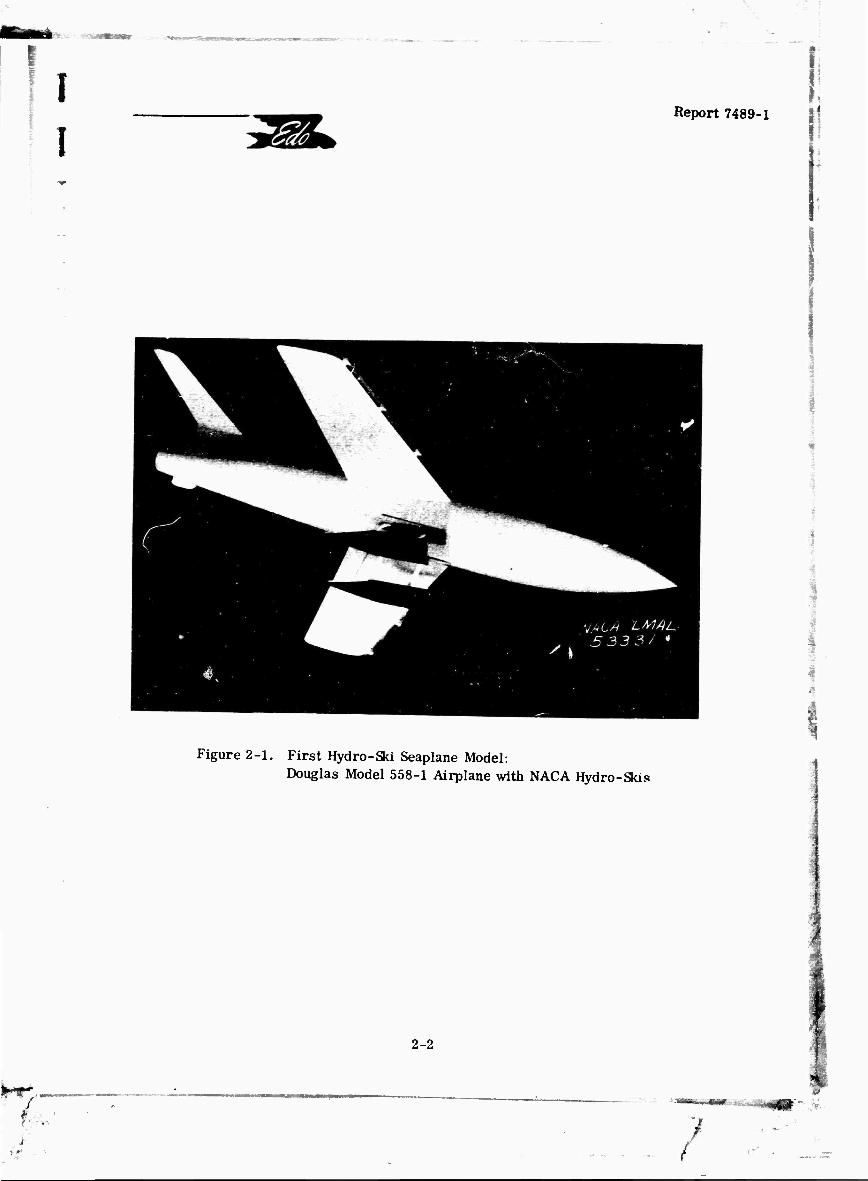
First Hydro-Ski Seaplane Model: Douglas Model 558-1 Airplane with NACA Hydro-Skis 2-2
First Full-Scale Seaplane Hydro-Ski Installation: Grumman OA-9 Airplane with Edo Hydro-Skis 2-4
Grumman OA-9 Seaplane with Edo Single Main Hydro-Ski 2-5
Grumman JRF-5 Airplane with Edo Single Hydro-Ski . , . 2-6
North American SNJ-5C Airplane with All-American Flat-Bottom Skis and Wheels 2-7
Cessna OE-1 Airplane with All-American Ski Assembly . . 2-8
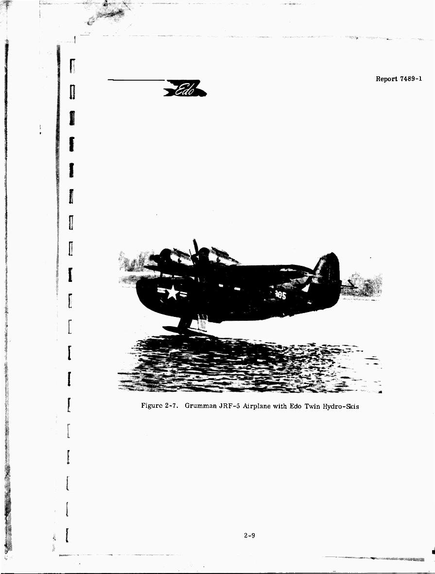
Grumman JRF-5 Airplane with Edo Twin Hydro-Skis . . . 2-9
First Full-Scale Jet-Powered Hydro-Ski Seaplane: Convair YF2Y-1 with Twin Hydros-Skis 2-10
Single Large Hydro-Ski Installation on XF2Y-1 2-12
Single Small Hydro-Ski Installation on XF2Y-1 2-13
Chase YC-123E Aircraft Equipped with Stroukoff Pantobase Landing Gear 2-14
DeHavilland U-1A Airplane with All-American Hydro-Ski 2-15
Martin PBM-5 Airplane with Large Edo Hydro-Ski .... 2-1(5
Martin PBM-5 Airplane with Small Edo Hydro-Ski .... 2-17
Lake LA-4 Amphibian with Thurston-Erlandsen Hydro-Ski Installation 2-18
i I VI

;
■v
■
I I I
-
I Report 7489-1
vflA
ABSTRACT
This report is the first part of a two-phase study for the survey and analysis of hydro-ski seaplane technology. As such, it contains qualitative correlations of the results of all data to define optimum hydro-ski shape, spray characteristics, and longitudinal, lateral, and directional stability during take-off anu landing. A bibliography of hydro-ski technology is also included. The Phase II report, to be issued at a later date, will contain related parametric analyses.
These two documents will contain all of the information required for establishing a preliminary hydro-ski configuration for a given set of design criteria and thereby eliminate the need to review the entire vast literature on seaplane hydro-skis.
Vll

«-._
f r
r
Report 7489-1
1. INTRODUCTION
■
;
Ci
i
■■
i
i
(
. i.
This report covers the work done by Edo Corporation on Phase I of ONR Contract No. N00014-66-C0126. The basic purpose of this contract is to produce, by means of a survey and analysis, a single-source document defining the present state of knowledge of seaplane hydro-ski engineering technology.
Such a document, to be furnished as the end-product of this project, will contain all of the information required for establishing a preliminary hydro-ski configuration for a given set of design criteria and thereby eliminate the need to review the entire vast literature on sea- plane hydro-skis. This information could then be used to rapidly assess the potentialities of hydro-skis for given applications and would also furnish specific quantitative guidelines for the preliminary design of hydro-ski installations.
The specific tasks assigned under this contract are as follows:
1. To conduct a literature search for all analytical and experimental data on aircraft hydro-skis and compile a bibliography;
2. To qualitatively correlate result? of all data to define optimum hydro-ski shape, spray characteristics, and longitudinal, lateral, and directional stability during take-off and landing;
3. To quantitatively correlate results of all data to define hydro-ski size, ski location with respect to strut and aircraft, ski and strut resistance, ski loads and load factors in waves, strut attachment to the aircraft, effects of strut size and length, and installation weight.
The first two of these tasks have been accomplished under Phase I of this project, as fully described in this report, and the Task 1 bibliography forms Section 8 of this report. This listing, which covers about 200 references, is believed to encompass practically all of the published literature relating to seaplane hydro-skis. In compiling this bibliography, material relating to seaplanes, seaplane hulls, and other types of seaplane appendages (tip floats, hydroflaps, hydrofoils, etc.) was deliberately excluded.
To insure that the survey would reflect the most current knowledge, a number ol per- sons associated with agencies presently most active in the hydro-ski engineering field were interviewed. Details of these interviews are given in a series of inter-office memoranda reproduced in Appendix A of this report.
The bulk of thi.c report covers the qualitative correlation of hydro-ski information accomplished under the second task. However, for a coherent and definitive presentation of this information, the following introductory items have been included:
1-1
■

m *
v - . -,..
i Report 7489-1
YStä
(a) A historical review of hydro-ski technology;
(b) A brief explanation of the difficulties inherent in the rough water operation of conventional seaplanes;
(c) The fundamental principles of hydro-skis, explaining their ability to overcome the conventional seaplane's rough water difficulties.
In presenting the qualitative correlation of hydro-ski data, it was assumed that the reader will have at least some limited familiarity with conventional seaplanes, from the standpoint of hydrodynamic and structural engineering as well as flight operations. However, it is believed that much of this information will be readily appreciated by others lacking such background.
The hydro-ski seaplane, conceived in 1947, has since been the subject of many programs of research and development by various government agencies, academic institutions, and pri- vate contractors. For the most part, the R&D program on hydro-ski seaplanes has been sponsored by the Hydrodynamics Branch, Airframe Design Division, Naval Air Systems Command (AIR 5301).
As a result of several full-scale evaluations, it is generally recognized that proper appli- cation of the hydro-ski concept can yield substantial improvements in seaplane rough water capabilities for take-off and landing, over those furnished by a hull-type aircraft of the same size. Although U. S. Navy operational requirements have not involved any quantity procure- ment of hydro-ski seaplanes, there has been a considerable accumulation of technical litera- ture, reflecting the total sum of effort, knowledge and experience associated with hydro-ski application.
The principal purpose of this survey and study program is to synthesize the extensive and scattered literature on this subject into a single-source document. This will facilitate the tasks of the design engineer by providing him with a ready reference for the determination and justi- lication of optimum hydro-ski arrangements.
This report, together with a companion report to be issued following completion of the second project phase, will constitute the single-source document synthesizing contemporary hydro-ski technology.
-
1-2

». ;
Report 7489-1
2. HISTORICAL REVIEW OF HYDRO-SKI TECHNOLOGY
I I
Since the inception of the seaplane in the earliest days of aviation and, particularly along with the growth in aircraft size following the development of all-metal aircraft, the ultimate goal of many seaplane designers became the development of an open ocean seaplane capable of routine take-offs and landings in very rough water. * Initially, most of the attempts used to achieve this goal were through increases in aircraft size. It was soon realized that this ap- proach, in itself, was inadequate and that it would have to be supplemented by relatively radical changes in the basic seaplane hull configuration.
The most notable developments in this area, achieved mostly through towing tank experi- ments, were the "high length-beam ratio hulls" and the "extended afterbody hulls" which, al- though yielding significant improvements in the seaplane's rough water capabilities, still fell short of the open ocean performance goal.
It is interesting that what is now one of the most promising approaches toward the devel- opment of an open ocean seaplane, that is, the use of hydro-skis, originated from a different requirement, namely, the development of the high-speed seaplane. The introduction of the jet- engine and the rapid development of jet-powered high-speed landplanes led seaplane designers to consider even more radical seaplane hull configurations such as those using faired steps, retractable steps, etc.
In 1947, John R. Dawson and Kenneth L. Wadlin of the NACA's Langley Towing Tank de- signed and model test^tj a set of twin hydro-skis on a dynamic model of the Douglas D-538 jet propelled airplane. ") This configuration, shown in figure 2-1, essentially retained the streamlined fuselage of the original landplane design, but converted it to a seaplane by making it watertight and designing the twin skis so that they would retract flush with the fuselage bottom. The initial tests of this configuration revealed excessively high water resistance in take-off (later reduced by chine strips on the after portion of the fuselage) but, otherwise, indicated very satisfactory take-off and landing performance and stability characteristics. However. the landing impact load alleviation capability of the skis actually went unnoticed at that time. (D
I
While NACA was developing a feasible hydro-ski configuration for application to high speed seaplanes, Edo Corporation had contracted with the Air Force for the design study of an Arctic jet-powered fighter aircraft having operational capability for water, ice, and snow. The originally proposed concept incorporated a strengthened shock absorbing keel, and it was planned to modify an existing OA-9 airplane for a full-scale demonstration of the feasibility of this approach.
* The other principal problem area of open ocean seaplanes, that is, resting on the rough water surface, is not considered herein. ** Numbers in paranthesis refer to Bibliography Entry Numbers, Section 8.
!
2-1
i ■*mm*SäämmmtUWt '^!'*f .-'■
f
I I
Report 7489-1
WA
\.
Figure 2-1. First Hydro-Ski Seaplane Model: Douglas Model 558-1 Airplane with NACA Hydro-Skis
2-2
/
i y
y

*
1'
F E r
r
n
r
[ [ i
[
i
Report 7489-1
Directly prior to the start of this modification program, the results of the iNACA hydro- ski development program became known. Edo Corporation thereupon recommended that the hydro-ski concept be adopted for the alighting gear system of an Arctic fighter in preference to the one originally proposed. Accordingly, a hydro-ski configuration was designed for the OA-9 aircraft. Towing tank tests of a l/8-scale powered model perforr.ed by NACA gave extremely promising results. It was, in fact, these model tests that gave the first definitive indication of the impact load alleviation capabilities of hydro-skis. (5)
Edo Corporation then proceeded with the design and fabrication of the first successful full-sca.'e hyaro-ski seaplane which was initially flown in October, 1948 (figure 2-2). The flight test performance even exceeded towing tank expectations, in that water operations with only a single main hydro-ski were proven feasible (figure 2-3). Air force sponsorship of Edo hydro-ski development programs terminated at this time.
The Navy Department, impressed by the potential demonstrated by the OA-9 hydro-ski installation, undertook the further financial support for hydro-ski application to water-based aircraft. Edo Corporation then designed and modified a JRF-5 (Navy designation for OA-9) to incorporate a single hydro-ski installation. ITie Navy flight tests of this hydro-ski seaplane were conducted in 1952 with both a rigid support strut and a shock absorber support strut (figure 2-4).
Concurrent with this program, the Navy also sponsored a ski development for land-based aircraft. This concept, fostered by the All-American Engineering Co., and considered to be applicable to Marine Corps operations, would permit an aircraft to take off from and alight on the water, with the flight beginning and ending on the beach o- a floating barge. Navy evalu- ations of this type of hydro-ski aircraft were conducted in 1952 on a SNJ-5C (figure 2-3) and an OE-] (figure 2-6) in 1953.
Again with respect to the subject of hydro-skis for water-based buoyant aircraft, although the Navy flight tests showed that the JRF-5 with a single hydro-ski had excellent rough water performance, too much pilot skill was required to overcome the tendency toward lateral instability as the hydro-ski emerges. It was felt that this characteristic, inherent in a single hydro^ki design, could be overcome by means of a twin side-by-side hydro-ski configuration.
The next step in the program was an Edo Corporation twin-ski modification of a JRF-5 (figure 2-7). Navy tests of 1953 showed that the twin-ski configuration did improve lateral stability, but the most advantageous feature of the design was found to be the integral beach- ing wheels in each hydro-ski, which considerably simplified launching and beaching operations.
The Convair Division of General Dynamics had also been active in hydro-ski development and accomplished, in 1953, the first successful flight of a jet-powered hydro-ski seaplane (figure 2-8). This extensive program also included, in addition to the original twin-ski
2-3
: - - - ■ iTftll^-,! '_j| ^
.

f Raport 7489-1
VSfA
Si
c o
o
i o
« s fH TO
«I
i
cn i
< O
-3 C 3 cd £ g
fa Ü
I (M
3 he
2-4
■^W
► «

r Report 7489-1 WA
Figure 2-3. Grumman OA-9 Seaplane with Edo Single Main Hydro-Ski
I 1 2-5
■ •
.

)-l I I I
Report 7489-1
VUA
(a) Rigid-strut configuration.
(b) Oleo-shock-strut configuration.
Figure 2-4. Grumman JRF-5 Airplane with Edo Single Hydro-Ski
% i
;^'
2-6
/
■ >

F
^
;
r r i
yf'A
.■ . ■
■
■
Report 7489-1
0) a»
■u c
5^ 6
I cd
i-H
c ü •^^
J3
c cd
& < ü in
i »-3 z CO
fi Ed o
ITJ I
IM
u &
2-7

-*>_ - JV *t.
)-l
\
I YMi
Report 7489-1
(a) Three-quarter Rear View
(b) Close-up View of Skis
Figure 2-6. Cessna OE-1 Airplane with Ail-American Ski Assembly
2-8
!▼*•**
i. bANKMOm
2:
1
0 I r i E
i
i
Report 7489-1
YS'Si
Figure 2-7. Grumman JRF-5 Airplane with Edo Twin Hydro-Skis
2-9

I
v.» - te-
I I [
ye'A
Rqaort 7489-1
Figure 2-8. P^irst Full-Scale Jet-Powered Hydro-Ski Seaplane: Convair YF2Y-1 with Twin Hydro-Skis
43: 2-10
3f

I I I I 0 0 0
r
.
Report 7489-1
arrangement, a single large hydro-ski in 1954 (figure 2-9) and in 1957, coordinated with Mr. E. H. Handler of the Naval Air Sytems Command, a single small hydro-ski Research Program (figure 2-10). In this same period, the Air Force undertook the sponsorship of an all-purpose landing gear, which included a set of hydro-skis. Stroukoff Aircraft Corp. - oration designed and built such a pantobase landing gear for the YC-123E, which was flown in 1955 (figure 2-11).
Concurrent with these developments, the All-American Engineering Company was actively engaged in adapting planing hydro-skis to the wheels of land-based aircraft. After its initial successes with a Piper Cub, Stinson OY, SNJ-5C, and OE-1, hydro-ski installations were also flight tested in the XL-17D "Navion'- and an Army U-1A "Otter" (figure 2-12).
As the Navy flight test program on the twin-ski JRF-5 was nearing completion, Edo Cor- poration proposed to the Navy that a P5M aircraft be equipped with a hydro-ski to enhance its ASW capability. Feeling the need first for operational experience on a hydro-ski seaplane in the patrol aircraft weight category, the Navy contracted with the Martin Company for a hydro- ski modification to the PBM-5, with Edo Corporation acting as subcontractor for the design and manufacture of the hydro-ski and strut. This configuration, in which the hydro-ski could be set at three different vertical extensions, first flew in 1955 (figure 2-13). Here again, the Navy evaluation reported excellent rough water behavior, with marginal lateral control at ski emergence as the primary problem.
During the Navy evaluation in 1958, of the PBM-5 with a single hydro-ski, Edo Corpora- tion designed and fabricated a geometrically similar but smaller hydro-ski for the aircraft (figure 2-14). The flight tests demonstrated that such a penetrating type of hydro-ski displayed excellent rough water potential and furnished a distinct improvement over the larger hydro-ski installation in lateral stability at unporting.
Unfortunately, this PBM-5 airplane was destroyed by fire while it was in its hangar so that the prototype capabilities of this hydro-ski installation could not be more fully explored. Further prototype testing of newer hydro-ski designs is currently being accomplished by Thurston Aircraft Corporation through use of a Lake LA-4 amphibian (figure 2-15).
Except for the initial NACA demonstration of hydro-ski feasibility, the preceding dis- cussion has been limited to a description of those hydro-ski developments which culminated in full-scale flight tests. Concurrent with these prototype installations, there have been a number of specialized experimental and analytical investigations dealing with fundamental aspects of hydro-ski applications which have furnished a substantial portion of the total knowledge of hydro- ski technology. The bulk of these studies have been performed by NASA, Davidson Laboratory, All-American Engineering, Convair, Edo, Grumman, and Martin. Most of these studies are related to the following subject areas:
A. Systematic measurements of planing loads;
B. Definitive formulation of laws for principal planing characteristics;
2-11

■
I
WÄ
Report 7489-1
-
,•, ■
:
- ^^te^
■■sls-^> ■
Figure 2-9. Single Large Hydro-Ski Installation on XF2Y-1
2-12
I

1
r
i
r 11
•?//j
Report 7489-1
SKI AREA 12.8 SQ. FT.
SKI BEAM ]6 IN.
■ m
J —
i
; Figure 2-10. Single Small Hydro-Ski Installation on XF2Y-1
! 2-13

I I I
Report 7489-1
V//A
u
2 c
o
o u
a a 3 cr
Ed
IM o u
n
I
u 9) M
JS U
i
SD
7- 2-14
7

r VS*A
Report 7489-1
•
r r
j i
c - •a
u
< i
< J3
1/
a -
< 1
e
Q
rH I
2-15

I i VS/Ä Report 7489-1
-t •»>.. .-.
- > ■. ■ ' ' ■
*■■■ :»•■ >'■*?'
—- ^L" ■ ' -—^ - —■^T' •_ J
figure 2-13. .Martin PBM-5 Airplane with Large Edo Hydro-Ski
2-16 I
•-*4i.

1 f
i 0 n
r r
Report 7489-1
V//Ä
\
Figure 2-14. Martin PBM-5 Airplane with Small Edo Hydro-Ski
2-17

yf/A Report 7489-1
-
i
: 4
is
■
-
■
-'
;>4 a ■
"
. -
Figure 2-15. Lake LA-4 Amphibian with Thurston-Erlandsen Hydro-Ski Installation
2-18

3.
I r
r r r i E r r
r
WÄ Report 7489-1
C. Effects of beam loading on impact loads and aircraft behavior;
D. Additional impact load alleviation obtainable from shock absorbers;
E. Effects of surface proximity and ventilation inception;
F. Scale effects:
G. Impact theory.
Finally, this historical review would be distinctly incomplete if no mention was made of the flight testing of the prototype ski installations by the private industrial companies and, more particularly, by the U. S. Naval Air Test Center, Patuxent River, Maryland. These efforts have had a major effect on the course of seaplane hydro-ski development.
I J
:
i: i
2-19
*■ -" ■■ fittfe», ^ -4 *

T
!
VS/A
3. PRINCIPLES OF HYDRO-SKI APPLICATION
Report 7489-1
3-1
The basic principles relating to the hydro-ski application are perhaps best illustrated by first considering the behavior of a hull-type seaplane during take-off and landing.
In relatively calm water, the transition from the displacement to the airborne condition (and vice versa) is accomplished in a gradual manner, with changes in trim occurring only slowly over a small range of values. Because of the inherently slow trim changes, such as would occur in a stick-fixed take-off or landing, the pilot is in full control of the aircraft atti- tude, except during the low-speed displacement range.
-
However, this situation changes radically in the presence of waves whose heights are sufficient to influence the aircraft motions. In this situation, the waterborne airplane continu- ously experiences rapid pitch variations whose frequency and severity depends on the sea state. As water roughness increases, the associated high hydrodynamic forces and moments applied to the seaplane hull, in conjunction with the large induced angular motions, causes a decrease in pilot control effectiveness. Catastrophically dangerous attitudes may soon be reached, where- by the aircraft may either stall out and strike the water at sink speeds adequate to produce hull impact loads exceeding the hull design values or, make contact in a low trim attitude and dive below the surface. Such uncontrollable motions are a natural consequence of attempting to oper- ate a conventional hull-type seaplane on a varying-contour air-water interface.
- The aircraft motions induced during rough water operations are somewhat analogous to
those experienced when flying through turbulent air. It is readih understood that, in turbulent air, the resultant dynamic forces vary principally because of changes in wing angle of attack. However, in the case of a dynamic lifting surface such as a seaplane hull bottom, in addition to the effects of trim change, the turbulent air-water interlace also induces large variations in wetting of the dynamic surface with correspondingly large changes in both center of pressure and hydrodynamic force. It is this combination oi large hydrodynamic impact forces and mo- ments which make conventional seaplane operation in rough water extremely hazardous, if not impossible.
Some gains in seaplane rough water capability have been achieved by modifying the hull lines, but it is the application of hydro-skis which has resulted in the most significant improve- ments achieved to date. In principle, the hydro-ski is essentially a low-aspect ratio planing surface extending beneath the seaplane hull which, in the moderate to high speed range below take-off and landing, develops sufficient hydrodynamic force to permit seaplane operation on the water surface while maintaining the hull proper clear of the waves. Since the hydro-ski surface area is relatively small as compared with a seaplane hull bottom, it will maintain the center of pressure in the region of the aircraft center of gravity and prevent the development of excessive hydrodynamic forces and moments.
r 'f-

r
r r
r r r
r
[ r
i.
L i 1:
-
Report 7489-1
Thus, the hydro-ski is a rough water device which prevents the build up of excessive hydrodynamic loads during take-off and landing by preventing the hull from contacting the water under high speed conditions. Further, from the landing viewpoint, where dissipation of the aircraft's vertical momentum at initial water contact is required, a hydro-ski installa- tion can be best regarded as a shock absorber system. A hull-type seaplane in landing pre- sents a broad large surface to the water, which can develop extremely high hydrodynamic forces at a relatively low draft. On the other hand, a hydro-ski, with its comparatively smaller width and planform-area, limits the magnitude of the hydrodynamic force. This effect is achieved primarily by the ski's narrow width (beam) which limits the load that can be developed for given values of speed and trim and is thus often described as the "wetted chines" effect. The support strut provides a "stroke" of sufficient length to insure that, when the hull does contact the water surface, the aircraft's sink speed will have been reduced to a value which will not cause high hull loadings.
3-2
« * —'1 t

T
I f
Report 7489-1
V/5M
t
4. HYDRO-SKI CONFIGURATION CHARACTERISTICS
4.1 GENERAL
It is seen that the basic principles of hydro-ski application are fairly straightforward and simple. However, experience has shown that there are a multitude of design problems that must be carefully considered and solved before a successful hydro-ski installation is achieved. The basic reason for this can be traced to the fact that a hydro-ski installation must be designed to operate in transient conditions on a randomly varying interface.
There are many hydro-ski configuration characteristics which the designer must estab- lish, of which the most fundamental are the hydro-ski area, the strut length, and the ski loca- tion. The primary consideration in establishing the hydro-ski area is the desired speed for raising the hull clear of the water, that is, the unporting speed. This value depends on the planing lift characteristics of the hydro-ski, as well as on the aircraft's aerodynamic charac- teristics.
The strut length selected is usually determined by the rough water design criteria but also has significant limitations imposed by considerations of strut hydrodynamic resistance. As stability considerations during take-off and landing are most important for the location of the hydro-ski, towing tank tests are utilized to establish the final position.
In reality, the various hydro-ski design parameters are closely related to several de- sign conditions, so that the final choice of any single item usually represents compromises in the requirements for each condition. For example, the strut length, in addition to being a primary factor in establishing the rough water capability of the aircraft, influences the un- porting trim angle, the hydrodynamic resistance, and the stability of the configuration. Consequently, whenever a design parameter is changed to improve one aspect of the per- formance, it becomes necessary to examine critically the effects of this change on other per- formance aspects.
Hydro-ski configuration design details can also be of great importance in the develop- ment of a successful installation. This is especially true in regard to those features which influence the spray characteristics. Spray problems have generally caused most of the major difficulties encountered during full-scale evaluation of hydro-ski seaplane performance. It has been found that relatively minor design modifications are often adequate for significant improvements in the spray patterns.
This section will discuss the various hydro-ski configuration parameters and their qualitative relation to the take-off and landing behavior of hydro-ski seaplanes.
4-1
-•
w
r
i r
11
; i [ [ [ [ I [ [ i: i i
Report 7489-1
4.2 HYDRO-SKI CHARACTERISTICS
4.2.1 Main Planing Characteristics
In the determination of the appropriate size of hydro-skis required to effect unporting at a selected speed, it is essential that the designer be able to predict the hydrodynamic lift developed by the hydro-ski at the instant the bow of the ski emerges through the water surface. This is readily accomplished by existing formulas which express the dynamic lift coefficient of a planing surface as a function of its trim, wetted aspect ratio, and deadrise.
Other significant hydrodynamic characteristics of the planing hydro-ski are its drag and center of pressure. The three • irameters; lift, drag, and center of pressure, are termed the "main planing characteristics". Substantial experimental and theoretical efforts have been made to establish accurate equations for these quantities.
Two sets of semi-empirical equations for the lift and center-of-pressure are in current use; both of these are based on the extensive data obtained in towing tank studies. The NASA planing equations, which do not account for buoyancy effects, are considered to be most accu- rate for high Froude Numbers, while the Davidson Laboratory equations, which do account for buoyancy, are presumably more accurate at lower Froude Numbers. Thus, it may be said that an all-inclusive formulation of the hydrodynamic planing laws is still lacking.
For high trim angles, the drag of a hydro-ski may be taken simply as the lift multiplied by the tangent of the trim angle. For lower trim angles where skin friction becomes significant, suitable procedures for the calculation of planing drag have been developed by Davidson Labora- tory and the David Taylor Model Basin.
As will be seen later in this report, the planing lift relations are also of significance with respect to hydro-ski landing impact values which are usually estimated by the "equivalent planing velocity" method.
(See Bibliography Entry Numbers: (4), (6), (11), (13), (16), (19), (25), (26). (36), (43), (45), (46), (47), (48), (50), (51), (52), (54), (55), (59). (61), (62), (65), (65), (68), (69), (70), (77), (79), (82), (83), (84), (85), (88), (112), (113). (114), (118). (122), (124), (132), (135), (139), (140), (143), (144), (150), (154), (156), (174), (180), (187), (192).)
4.2.2 Beam Loading
3 The non-dimensional beam loading coefficient, C. = W/. gb (where W = aircraft
o gross weight, p = water mass density, g = gravity acceleration, b = hydro-ski beam), is the basic quantitative parameter relating ski dimensions to aircraft weight. This coefficient may be regarded as a hydrodynamic analogue of the aerodynamic wing loading. Just as the wing loading is the fundamental parameter affecting the magnitudes of an aircraft's gust loads and gust responses, the ski beam loading affects the magnitudes of the seaplane's landing impact loads and the associated seaplane motions.
4-2

I I
i
Report 7489-1
As compared with a low length-beam ratio hydrofoil, the relatively high length-beam ratio hydro-ski affords, while piercing the water surface, a gradual change of wetted area with draft, as well as significant forward travel of the center of pressure with decreasing
4-3
i
More specifically, for the same seaplane gross weight, and under identical initial water impact conditions of resultant velocity and trim, the hydro-ski seaplane with the higher beam loading will develop a lower hydrodynamic impact load, (assuming the strut to be of adequate length). An increase in maximum water penetration is also realized with the nar- rower hydro-ski beam,
A general distinction is usually made between "large, non-penetrating" and "small, penetrating" hydro-skis. Non-penetrating hydro-skis are those of relatively low-beam load- ing coefficient, such that the ski bow does not submerge during the design impact conditions or, if submergence does occur, the maximum hydrodynamic impact load is developed prior to ski bow immersion. Penetrating hydio-skis are those of relatively high beam loading co- efficient such that, under the design impact conditions, the maximum hydrodynamic impact load occurs at the instant the ski bow immerses. Further submergence of the ski then pro- duces loads which are smaller than the (instantaneous) load occurring at bow immersion.
i When planing at high speeds in waves, large hydro-skis tend to develop hydrodynamic
forces sufficient to cause the aircraft to rebound from the surface. With a penetrating hydro- ski, because of the lower hydrodynamic lift, the aircraft is relatively insensitive to the water surface contour, and the ski thus has a greater tendency to "plow" through the wave crests.
A large hydro-ski is usually required for unporting at a speed sufficiently low to pro- tect the hull from high wave impact loads as take-off speeds are approached. A small hydro- ski is more suited for operating at speeds near landing and take-off, since the penetrating action limits the loads developed, but the ski size is inadequate to keep the hull above tne water at substantially lower velocities.
Large hydro-skis have typical beam loading coefficient values of about 10 while, for practical penetrating hydro-skis, the corresponding values may be anywhere from 50 to 200.
(See Bibliography Entry Numbers: (9), (10), (16), (24), (30), (31), (34), (35), (38), (40), (41), (42), (44), (45), (49), (64), (66), (67), (73), (75), (80), (131), (134). (149). (163), (169), (174), (188), (189), (190), (192), (193), (196).)
4.2.3 Length-beam Ratio
By definition, hydro-skis are low aspect ratio hydrodynamic appendages. In the early NACA towing tank model investigations which established the feasibility of hydro-skis, both high and low aspect ratio surfaces were examined. With the high aspect ratio hydrofoils, the airplane model tested could not make stable transition from "foil submerged" to "foil planing" conditions. This behavior is, of course, well known to those familiar witu the sport of water skiing.
/

f
:
■"
I
i i
n
r L
[
Y0Si Report 7489-1
trim during planing. Also, for the practical ranges of importing speeds, the low aspect I ratio hydro-ski approaches the water surface in a ventilated condition, where the flow is de-
tached from the upper surface. This reduces the tendency to develop the lift-force breaks associated, for example, with hydrofoils of subsonic airfoil section, which induce pmergence
f instability fay cavitation or. in the absence of cavitation, through a rapid lift loss during the transition from fully-wetted submerged flow to the planing condition. These desirable in- herent characteristics of the high length-beam hydro-ski are responsible for its present-day
m advantage over the hydrofoil for applicability to seaplane configurations in spite of the sub- cavitating hydro-foil's higher lift-drag ratio potential.
r« Hydro-ski length-beam ratios range typically from 3 to 8. The lower value is gener- ally adequate lo preclude the possibility of unstable "hydrofoil" effects while structural con- siderations generally place an upper limit on the practical value for higher length-beam ratios.
(See Bibliography Entry Numbers: (24), (30), (33), (68), (78), (163), (181).)
4.2.4 Deadrise
In engineering practice, the final determination of the hydro-ski deadrise, or trans- verse section of bottom contour, is the result of practical considerations involving impact loads, planing characteristics, and ski retraction.
From a theoretical viewpoint, a flat-bottom (zero deadrise) hydro-ski is to be avoided because of the possibility of a zero trim impact, which nould (theoretically) result in an in- finite hydroöynamic force. Practically however, fluid compressibility, trapped air, struc- tural elasticity, and the improbability of achieving a zero trim impact over an appreciable length of the ski, all combine to give finite load values. Nevertheless, in spite of these mitigating conditions, excessively high impact loads may result under certain circumstances. A moderate amount of deadrise, (10°), is considered adequate to eliminate concern for a zero trim impact.
From theoretical two-dimensional impact considerations it is possible to derive a variable deadrise bottom shape (convex keel, concave toward chine) which will develop a constant force during the non-chine immersed portion of the impact process. Although hydro-ski applications of this "constant force" bottom have demonstrated no significant difference in impact behavior, as compared with a vee-bottom hydro-ski of the same effective deadrise (angle measured from keel to chine), the low local deadrise in the vicinity of the chine tends to reproduce the beneficial effects of chine flare in reducing the spray height under planing conditions. The latter portion of this statement must be regarded cautiously since towing tank data indicates chine flare effectiveness only at low trims while full scale flight tests indicate the overall effectiveness of chine flare in reducing spray height.
4-4
V'

I I v/tÄ
Report 7489-1
r
! It is anticipated that an operational aircraft hydro-ski will be retractable. Conse- quently, in order to minimize space requirements and eliminate the additional complexity of well-covering doors, it is desirable to design the hydro-ski bottom for flush retraction against the hull bottom. Considerable planing data has been accumulated showing that this practical approach in establishing the basic bottom contour of the hydro-ski is entirely acceptable.
(See Bibliography Entry Numbers: (4), (6), (26), (33), (38), (40), (43), (47), (48), (51), (63), (64), (66), (67), (69), (73), (75). (79), (82), (83), (84), (85). (88), (113), (118), (127), (139), (143), (149), (174), (179), (192), (193).)
4.2.5 Planform
The planform parameters most significant for hydro-ski hydrodynamic qualities are the shapes of the ski bow and stern. The bow shape is of particular importance because )f its basic effect on the spray characteristics during the ski unporting process. Experience with several prototype hydro-ski seaplanes has shown that these spray effects can create one or more severe problems involving: power loss and/or erosion due to engine and propeller wetting, high resistance, and excessive spray impingement loads on vulnerable portions of the aircraft.
Towing tank tests comparing several basic nose shapes have demonstrated that a hydro-ski bow shape of long triangular planform, sharp profile, and no bow rise, is most effective for minimizing the height and extent of the heavy spray occurring during ski emer- gence. The effects of auxiliary devices such as slotted noses, drooped noses, etc. , on un- porting spray are considered separately in this report section.
T.'pered hydro-ski stern planforms also serve a number of important purposes. As compared with blunt trailing edges (square transoms), they:
(a) Produce more gradual rates of load build-up in individual impacts;
(b) Reduce ski and/or aircraft vibration when planing in short choppy waves.
Their effectiveness under the latter (b) conditions arises in part from their greater (equi- librium) drafts.
Thus, it appears that tapered stems resembling ship's boattails are clearly prefer- able to square sterns. On the other hand, experience has also indicated that excessive taper, such as a pointed stern, is undesirable because it creates high and heavy spray patterns.
(See Bibliography Entry Numbers: (49), (63), (72), (75), (77), (102), (105), (116), (122), (129), (138), (140), (141), (154), (163), (169), (176), (179). (193).)
4-5
/
/
f r i r r
Report 7489-1
D r [
i
1
r r [ [ [ [ [
4.2. 6 Longitudinal Curvature
In designing practical hydro-ski configurations, it may be advantageous to incor- porate some longitudinal curvature into the bottom shape for, as an example, flush retraction to the hull. iModerate longitudinal convexity or concavity can be designed into the hydro-ski lines, and experimental data are available for estimating their effects on the main planing characteristics, i.e., lift-drag ratio, lift coefficient vs. trim and draft, and center of pres- sure location.
At relatively low speeds, prior to emergence, the hydro-ski essentially acts as a low- aspect ratio airfoil. In this fully wetted condition, therefore, the upper surface shape influ- ences the hydrodynamic performance. However, the low speed range is not critical for re- sistance, as is the high-trim unporting condition, in which the hydro-ski upper surface is unwetted. The contour of the upper surface therefore, need not necessarily conform to an airfoil shape. Towing tank data are available for evaluating the effects of upper surface camber on a hydro-ski when operating in the fully wetted condition. These data show that, for a given angle of attack, the lift coefficient increases with increasing camber. However, for a fixed lift coefficient, increasing the upper surface camber (and thereby the thickness) causes a reduction in lift-drag ratio. For most hydro-ski applications, therefore, hydrodynamic considerations may be secondary to others (such as retraction against the hull bottom) in estab- lishing the upper surface lines.
(See Bibliography Entry Numbers: (19), (26), (36), (64), (77), (78), (79), (80), (106), (114), (135), (156), (163,, (169), (192), (193).)
4.2.7 Hydro-ski Cross-Section
The previous discussions on deadrise, planform, and longitudinal curvature are implicitly related to the hydro-ski cross-section. It is seen that hydrodynamic considerations may often be of secondary concern in establishing the details of the hydro-ski lines. All that is primarily required of the hydro-ski is that it be representative of a low aspect ratio surface. For the most part, the hydro-ski cross-section may be determined by strength criteria. How- ever, in regard to the transverse section of the hydro-ski bottom, in order to obtain an efficient planing surface, sharp chines are required to give a clean f'.ow breakaway. Other- wise, the flow tends to cling to the sides of the hydro-ski, resulting in loss of lift and increased friction drag.
(.See Bibliography Entry Numbers: (12), (77), (106), (163), (192), (193), (196).)
4.2.8 Auxiliary Features
As with many basically simple devices, significant improvements in hydro-ski perfor- mance over its operational range can be obtained by suitable modifications which, although adding ic complexity and cost, result in worthwhile gains.
4-6
(

1 r
Report 7489-1
4.2.8.1 Slotted Nose
As previously mentioned, severe operational problems have sometimes occurred on full-scale hydro-ski seaplane installations during the unporting process. One of these in- volves a heavy burst of spray which is generated from the bow of the emerging hydro-ski, and is thrown upward, sometimes practically enveloping the aircraft, obscuring pilot vision, causing propeller thrust reduction and erosion, as well as engine corrosion.
The main spray pattern of a planing surface is generated in the region where it intersects the water surface. The relatively high normal pressures acting on the "spray root" region of the bottom surface in conjunction with the high trims associated with unporting are responsible for the hugh quantity of heavy spray.
One means of combatting this effect is by means of a slotted nose at the bow of the hydrc-ski; this both prevents the build-up of the high pressure in this region, and redirects the spray, which would normally be thrown upward, towards the horizontal. Full-scale evaluation of this feature has demonstrated effectiveness on a large hydro-ski. There may be less need for a slotted bow on a penetrating hydro-ski (as was demons* ated on the small PBM ski) since, with higher unporting speeds, aerodynamic control may be available to maintain reduction in emergence trim which, in itself, tends to improve the spray character- istics.
(See Bibliography Entry Numbers: (103), (104), (122), (124), (128), (163), (172), (175), (176), (177), (178), (190).)
■
4.2.8.2 Drooped Nose
Another approach for reducing the burst of heavy spray generally occurring at hydro-ski emergence is by means of a drooped nose hydro-ski. The heavy spray is, of course, a direct consequence of the high trim at unporting and the drooped nose reduces the effective trim at the ski nose while the ski bow region pierces the water surface.
(See Bibliography Entry Numbers: (105), (122).)
4. 2. 8. 3 Spray Strips
In addition to the momentary heavy spray occurring at hydro-ski emergence, ex- cessive spray may also be encountered during the planing regime. The maximum planing spray height has been established to vary as the square of the speed and directly with the trim. It has also been established that although deadrise angle has only a moderate effect on spray height, the maximum spray height occurs at 10c deadrise. Vertical spray strips along the chine of a planing surface have proven to be effective in reducing planing spray height. Al- though some towing tank measurements demonstrate that vertical chine strip dapths as low as
4-7
'""2
^:':9

r
.
Report 7489-1
2 percent of the beam are effective as spray height reducers, it should be noted that the effec- tiveness of such shallow strips decreases with increasing speed and trim. A spray strip depth of 5 percent of the ski beam constitutes a near-optimum and highly effective value.
(See Bibliography Entry Numbers: (15), (16), (22), (51), (72), (97), (105). (127), (129). (139), (144), (145), (156)? (169), (170), (179).)
4.2. 8. 4 Trailing Edge Flaps
Relatively large hydro-skis tend to produce unporting speeds below which elevator control is ineffective. Consequently, high emergence trims with accompanying excessive high resistance and spray, may occur. Although aerodynamic forces may be inadequate to provide the pilot with sufficient longitudinal control to reduce the trim, a hydro-ski trailing edge flap has the inherent capability of doing so. The one full-scale attempt to use this type of device was unsuccessful. In the take-off runs, although the maximum trim at unporting was reduced, severe porpoising developed while the flap was being retracted in the planing regime. In the landing runs, excessive bow down motions occared upon lowering the flap at too high a planing speed. This particular trailing edge flap design was a two-position system, which may have contributed to its detrimental features. Nevertheless, the fact that the hydro- ski trailing edge flap did reduce the maximum unporting trim, does indicate that, by proper design, it could be developed into a useful device to provide hydrodynamic trim control at speeds where adequate aerodynamic trim control does not exist.
(See Bibliography Entry Number: (103).)
I [ [
4.2.8,5 Variable Area
f
The hydro-ski area required for the desired unporting speed may be excessive with respect to its impact charac eristics at getaway and landing speeds, for which a smaller area hydro-ski is more appropriate. These conflicting requirements have led to the concept of a \ jriable area hydro-ski, wherein mechanical methods are used to obtain a reduction in ski area after unporting. This reduced area is also used for landing, wherein the small area is used for the original impact, and the larger area is introduced directly prior to the small area submergence.
One design concept for a variable area hydro-ski incorporates longitudinally pivoted side flaps. This design has been successfully applied to a full-scale non-buoyant hydro- ski aircraft. In this case, the larger area, although not related to unporting speed, is used to permit immediate planing as the aircraft makes a ramp-to-water entry.
4-8
.■i
- ■■ '»■

'
VftA Report 7489-1
Another design concept is the use of a "sub-ski" which can be retracted flush into a large hydro-ski. With this design, the large hydro-ski (and contained small hydro-ski) are extended until the unporting speed is exceeded and stable planing has been established. The large ski is then retracted, leaving the smaller ski extended until getaway. The process is reversed in landing. This design approach has been evaluated in towing tank tests where it was compared with a side flap-type variable area hydro-ski.
The towing tank tests revealed that, in comparison with the side flap type, the sub-ski type variable area hydro-ski had relatively poor trim and center of gravity limits of stability. An examination of both ski configurations reveals that the length of the side flap ski remains constant while the length of the sub-ski type is reduced by 1/2, when the area is reduced. It is likely that this inherent limitation of the available center of pressure travel was the cause of its poor stability characteristics.
(See Bibliography Entry Numbers: (16), (22), (31), (95), (96), (97), (138), (139), (140), (172), (176), (178), (186), (189).)
4.2. 8. 6, Integral Beaching Gear
A hydro-ski and strut combination extending downward from the hull naturally leads to ronsideration of an integral beaching gear arrangement. Beaching wheels have been successfully applied to prototype twin hydro-ski seaplanes to permit rapid and direct ramp-to-water transition. Towing tank test results have demonstrated that small beaching wheel protuberences from the hydro-ski keel result in only minor compromises in hydro- dynamic performance.
The associated mechanical design aspects depend upon the particular aircraft configuration. For example, it may be necessary to include a system which allows pivoting of the hydro-ski to accommodate the airplane attitude change that occurs in going from the ramp to the waterborne condition, A single ski configuration, of course, requires additional lateral support which could lake the form of beaching wheels in the wing tip floats.
Thus, it appears that, as compared with a hull type seaplane, a hydro-ski sea- plane offers excellent potential for simplifying beaching operations.
(See Bibliography Entry Numbers: (11), (22), (25), (95), (96), (97), (98), (99), (100), (112), (138), (139), (140), (141), (175).)
4-9
«-,

r r
^. :,
Report 7489-1 yf'Ä
4.3 HYDRO-SKI INSTALLATION CHARACTERISTICS
4. 3-1 Basic Installation Geometry
4. 3.1.1 Ski Location
\
\
[ L
I I I
[
1
Proper location of the strut-hydro-ski installation is necessary to ensure satis- factory longitudinal stability characteristics during take-off and landing. A ski location too far forward will cause excessive pitch-up, inducing premature rising of the aircraft, while too far aft a location will cause diving.
In general, it is desired that, in landings, the resultant hydrodynamic load vector pass through the airplane center of gravity, so that vertical motions are effectively deceler- ated with minimum generation of angular motions. Tow tank landing tests have clearly estab- lished that increasing hydro-ski beam loading tends to necessitate further forward ski loca- tions. This result is readily explained by the greater strut drag contribution associated with a penetrating hydro-ski.
Since the proper strut-ski location involves the correct balanr-e between aero- dynamic and hydrodynamic moments during both take-off and landing, towing tank model tests are employed for the purpose of establishing the optimum longitudinal position of a specific hydro-ski configuration.
(See Bibliography Entry Numbers: (1), (27), (30), (97), (111), (128), (130), (131). (169), (172). (176), (178), (181), (187), (188), (192), (193), (196).)
4.3.1.2 Hydro-Ski Incidence
Among other things, the main planing characteristics of ;i hydro-ski depend directly on the ski's trim angle, i.e. , the angle between the ski keel line ;!nd the water sur- face. When installed on a seaplane, the ski trim becomes the sum of the hull trim angle and the ski incidence relative to the hull keel. The latter angle thus becomes a design parameter and, as will now be made clear, is of consideuble importance in achieving an optimum ski installation.
The most basic problem area relating to ski incidence deals with the possibility of aircraft diving. Diving can be caused by the ski in two different ways. First, it is clear that if, for any reason, such as excessively low ski trim in ski impact during landing, the ski should develop negative vertical loads or even, under less extreme circumstances, inadequate positive loads, diving will result. Secondly, diving of the aircraft can also result, even though the ski generates substantial positive vertical impact loads, in the event that the re- sultant load passes aft of the seaplane's e.g., thus creating a net applied diving moment. This latter consideration makes clear both that the optimum ski incidence depends directly on the ski location relative to the aircraft and, also, that for any fixed ski location there is a well-defined upper limit of allowable ski incidence.
4-10
".

1
I I
Report 7489-1 Yf'A
It is also readily appreciated that, as compared with calm water landings, rough water landings are much more critical with respect to both sources of the diving action. A huiding on a wave flank reduces the ski's effective trim angle and can thus induce negative loads if the basic ski incidence is too low. Alternately, if the ski incidence is so great that impact loads produce diving moments, this effect is exaggerated in wave flank landings be- cause of the net load increase resulting from the increased effective flight path angle.
Finally, it may be noted that, because different ski beam loadings usually call for differences in ski longitudinal location, as has been indicated above, the ski beam loading has an indirect, but still definite effect on the ski incidence requirements.
The foregoing discussion serves to explain the principal towing tank test results relating to ski incidence. In a series of rough water landing tests covering a wide variation in ski beam loadings, it was found that the highest beam loading ski (C- - 600) required a far forward location and an incidence of 8° to eliminate diving. Although not explicitly de- scribed, it is clear that the diving tendencies occurring at the lower ski incidence values correspond to the first case described above, hi another .series of tests of a penetrating hydro-ski configuration, it was found that ski incidence improved the aircraft's landing per- formance in calm water by permitting a reduction in the aircraft's initial contact trim angle before diving occurred. On the other hand, the same ski incidence actually increased the aircraft's diving tendencies in rough water.
(See Bibliography Entry Numbers: (30), (111), (128), (130), (131), (133). (188), (191), (192), (196).)
4. 3.2 Strut Characteristics
4.3.2.1 Strut Location Relative to Ski
For the most part, the strut location relative to the ski is governed by structural and/or mechanical considerations rather than by hydrodynamic considerations. This is particularly true in the case of large non-penetrating and/or low aspect ratio skis where, for example, the strut location may be selected to minimize ski design bending moments, etc. For penetrating and/or higher aspect ratio skis, where strut location has a relatively smaller effect in the optimization of ski structure, the location can sometimes be varied slightly to improve the ski ventilation characteristics. In this case, the final choice of the strut location will be influenced by the strut cross-section, as further explained in Paragraph 4. 3, 2. 3,
4.3.2.2 Strut Length
It is apparent that the length of strut to which the hydro-ski is mounted is a funda- mental parameter in establishing the load alleviation capability of the attached hydro-ski. Too short a strut length will not protect the hull from high hydrodynamic impact loadings, while too long a strut will generally create problems relative to drag and stability.
4-11
i »•

D
r i L
[
f I I I I
.
Report 7489-1
Although a hydro-ski installation will increase the rough water capability of a given seaplane, for any particular hydro -ski installation there is obviously a sea state limit above which the ski-strut combination is ineffective in permitting rough water operations. As indicated above, there is a limit to which strut length may be increased for further im- provement in wave height capability.
Strut length selection is of major importance with respect to the design rough water conditions of the hydro-ski seaplane. It is obviously desirable to make the minimum strut length consistent with the rough water criteria.
Historically, it has been the practice to make the hydro-ski strut length equiva- lent to the design maximum wave height. Exoerience has shown that, for low beam loading hydro-skis, wave heights greater than the distance from the ski keel to hull bottom can be successfully negotiated. Existing full-scale results also indicate that for high beam loading (penetrating) hydro-skis, the ski extension should approximate the design wave height.
(See Bibliography Entry Numbers: (5), (8), (15), (20), (22), (23), (27), (30), (93), (102), (103), (104), (HI), (128), (145), (147), (175), (177), (181), (184), (190), (191), (192), (193).)
4. 3.2. 3 Strut Section
The only function of the hydro-ski support strut is to position the ski at the re- quired location below the hull. Any hydrodynamic forces developed by the hydro-ski support strut only serve to deteriorate the resistance and stability of the configuration.
Minimum resistance considerations will lead to the selection of streamlined strut sections. These, however, can give appreciable side loads under yawed conditions so that directional and lateral stability performance is comprised Consequently, the streamlined strut sections should be the smallest permissible consistent with structural strength require- ments.
AUhough a streamlined strut is indicated, the trailing edge should be of the blunt "base vented" type in order to enhance ventilation of the hydro-ski upper surface. This feature will contribute to precluding lift force breaks during unporting, with their attendant emergence instability.
Model tests have revealed a "choking" phenomenon in base-vented struts. It has been observed that the air rushing down the ventilated cavity can cause thin spray sheets, aft of the strut, to contact each other, thereby sealing the cavity from the atmosphere. It is likely that this effect does not apply to full-scale conditions, wherein spray sheets are not "solid" as they are under the surface tension effects at model scale.
As the strut side forces are the primary cause of directional and longitudinal sta- bility problems, further hydrodynamic design efforts are needed to develop relatively low
4-12

-im&m.
f
I Report 7489-1
dra^ sections with low lift slope curves. A possible strut section satisfying this criterion might be one having a step near the leading edge, or, alternately, having a blunt leading edge for the generation of a cavity clearing the entire strut section.
(See Bibliography Entry Numbers: (76), (86), (111), (114), (115), (123)^ (169), (192), (197).)
4.3.3 Shock Strut Mountings
Tn order to protect the seaplane hull from-high hydrodynamic impacts, a hydro-ski must, by necessity, be attached to a strut (or strut system) extending below the hull. In the interest of achieving the greatest possible hydrodynamic load reduction for any particular installation, considerable developmental effort has been spent on the incorporation of shock absorbers into the ski support structure.
The various analytical, model, and full-scale investigations of such installations have demonstrated that, for low beam loading hydro-skis, shock absorber mountings pro- vide significant load reductions over and above those with rigid struts. However, it has also been demonstrated that, in some hydro-ski installations, the shock absorbers can be the source of other severe problems.
For example, it was found in the first full-scale flight tests of a shock absorber- trimming hydro-ski configuration that the take-off trim limits of stability were unsatisfac- torily high and narrow, permitting take-off in calm water only. The oleo damping character- istics were then revised, which effectively improved the longitudinal stability during take-off but resulted in excessive cockpit vibrations during take-off in choppy water.
The conventional aircraft shock absorber tends to act like a rigid strut under a rapid loading rate or high frequency of load application. This is the situation that occurs during high speed planing over short steep waves. A lead rate-sensitive shock absorber has been developed which does not become "stiff" under rapidly applied pulses. Although a somewhat complex device, this "low-band-pass" shock absorber appears to offer a solution to the vibra- tion problem encountered when shock mounted hydro-skis plane in choppy waves.
Shock absorber-mounted hydro-skis may be of either the translating or pivoting type. A translating ski compresses the shock absorber strut without changing trim, while a pivot at the bow causes trim reduction during compression of the other type. Comparative towing tank tests show that both types are effective in reducing hydrodynamic impact loads of low beam loading hydro-skis, particularly at the lower wave length-height ratios, with slightly more load reduction exhibited by the translating hydro-ski.
In designing a shock absorber strut for the translating hydro-ski, it is necessary to ensure that the strut bending moments developed during hydrodynamic impact loading do not cause binding, which would prevent vertical motion of the hydro-ski.
4-13
'
#v •

,'.
I
I I I I I
1 ■ -
Report 7489-1
Because of the much lower impact loads achievable with high beam loading skis, the use of auxiliary mechanical shock absorbers does not appear warranted and, in fact, no tests of such combinations have ever been attempted.
(See Bibliography Entry Numbers: (14), (20^ (21), (22), (23), (24), (28), (29), (32), (60), (74), (91). (93), (94), (95), (96), (97). (98), (1- ■), (101), (109), (116), (119), (138), (139), (140), (141). (145), (146), (147), (152), (153). (155), (157), (158). (159). (160), (161), (162), (165), (167). (170), (171). (172), (173). (175). (182).)
4.3.4 Multiple Ski Configurations
It is obvious th; t, when planing on a single hydro-ski, the seaplane has inherent transverse (rolling) instability and that, correspondingly, stable roll attitudes can only be maintained through aerodynamic control initiated by the pilot. Through experience, it has been found that this problem is most critical in taking-off of conventional seaplanes equipped with large single skis at speeds just beyond ski unporting. In these configurations, the wing tip floats are too far above the waterline to provide hydrodynamic stability and, further, the airspeed may also be somewhat too low for adequate aileron control. (This difficulty is automatically eliminated, of course, with single small skis which result in higher unporting speeds.)
The lateral instability problem associated with large single skis can, of course, be overcome without change of unporting speed through use of twin (side-by-side) hydro-skis. Full-scale tests of twin ski installations have shown that, with proper design, not only is the inherent instability of the single ski completely eliminated, but considerable improvement in cross-wind planing maneuverabiliiy is likewise achieved. Another extremely important ad- vantage of the twin ski installatior. is its intrinsic suitability for the incorporation of integral beaching wheels. (Effects of non-simultaneous ski unporting are discussed in Section 7.)
No specific numerical criteria have yet been established for the basic design of twin ski installations. For example, in replacing a single ski with twin skis, a variety of ap- proaches (or combinations thereof) may be used whereby: the single ski planform area is maintained, or the single ski beam loading is maintained; the single ski aspect ratio is main- tained, or the single ski length is maintained; etc. Similarly, no precise criteria are avail- able for the lateral spacirg (tread) of twin skis and it appears that, in the past, guidance has been obtained from stand ird practice for landplane wheel gear, as modified by strut length and ski retraction requirements when necessary.
Another parameter affecting the lateral stability is the ski cant angle, as cant angles other than zero are sometimes desirable for retraction purposes. While no criteria for this quantity are presently available, they can be devised by utilizing the concept of metauentric height in conjunction with the known planing characteristics of rolled skis. (This type of consideration has been used in connection with the transverse stability of surface-piercing hydrofoils.) Further, it is obvious that, for the limiting case of narrow beam skis, the minimum criterion is that the normal to the ski keel line must pass outboard of the aircraft e.g.
4-14

Report 7 IH9-1
Twin hydro-ski instnllations have proven most successful when used with single- engine aircraft. When applied to a twin-engine aircraft, the advantages cited above were largely offset by the deleterious effects of the spray created during ski unporting. This spray was sucked into the propeller disks, engine cowling, and carburetor intakes, with such a large and rapid resultant reduction in propeller thrust that take-off performance became almost marginal. It follows that, in any multiple ski location, the location of the skis relative to engines and propellers is probably the most important design parameter,
A "tricycle" hydro-ski configuration consisting of a small nose ski and two main skis has been investigated in towing tank tests. Although this configuration was shown to be definitely feasible, it proved somewhat susceptible to longitudinal instability problems re- sulting from high hydrodynamic pitching moments in rough water.
(See Bibliography Entry Numbers: (1), (5), (8), (12), (18), (20), (22), (;}2), (70), (81), (95), (96), (97), (98), (99), (100), (101), (107), (109), (110), (116), (117), (120), (138), (139), (142), (145), (146), (173), (175), (181).)
4. 3. 5 Retraction System
It can be stated categorically that, on an operational aircraft, hydro-skis and their support struts will be retracted in flight to optimize aerodynamic performance. It follows that consideration of the retraction system must be regarded as a fundamental aspect in the design of the entire ski system which, in many cases, is liable to impose significant limita- tions thereon.
In view of the diversity of approaches available for design of retraction systems, past practice in this area has been rather limited. In the two cases where existing seaplanes were retrofitted with retractable skis, the retraction systems were designed to minimize aircraft modifications. In both of these (PBM-5 and HRV-1), thi," (single) ski can be re- tracted against the hull keel by vertical translation of the .;'rut into a hull well. Further, in the case of the PBM-5, the ski's upper camber and deck cross-section are geometrically incompatible with the hull's bottom lines. Systems of this sort may be considered definitely inadequate from the aerodynamic viewpoint which requires the ski gear to be fully retracted inside the aircraft structure through use of wells and doors, or, if external, to bs complete- ly flush mounted, such as on the F2Y. If wells are used for internal stowage of ski gear, their design will usually be complicated by watertightness requirements.
While little specific discussion of ski retraction systems can be made, it appears that future designs will rely on the mechanical ingenuity of the design engineer in the employment of such approaches as pivoted struts, telescoping struts, parallelogram linkages with multiple struts, etc., in conjunction with suitable actuation systems. In this connection,
4-15
■
■ -f

t 5 r
S;
r r r
0 o
! n P ij
r r:
E
t
: [
[
[
Report 74S9-1 star
it should be mentioned that, as the transverse cross-section of a hydro-ski is generally of secondary hydrodynamic concern, a hydro-ski with a "bent plate" cross-section is most advantageous for a simple retraction system. For this type of ski, the upper surface can be shaped to match with the hull bottom when retracted, and the associated aerodynamic drag penalty would be small.
(See Kbiiography Entry Numbers: (100), (102), (104), (106), (109), (147). (162), (164), (165), (167). ^72), (176), (178). (182), (183). (184), (190), (191).)
4-16

I I I
4.4
V/5J
DESIGN LOADING CRITERIA
Report 7489-1
4.4.1 Hydro-3d Load Criteria
Present day analytical procedures are adequate for determining the magnitude of the hydrodynamic load resulting from any single impact with given initial approach conditions. For any specific aircraft, it would also be a fairly simple matter to define a design critical impact condition by combining the highest values of landing speed, sink speed, trim, and wave slope. However, the improbability of the simultaneous occurrence of all four maxi- mum values under operational conditions would clearly result in a structurally overdesigned hvdro-ski.
It is much more rational to establish hydro-ski design loadings by considering real- istic impact conditions occurring during rough water landings, with due regard for the prob- abilit}' of encountering these conditions in the operational life of the airplane. This type of consideration must be combined with others involving the time-history of the ski-borne portion of landing runouts made through actual wave contours.
The computation just described, which includes heave, pitch, and surge response of the aircraft, is a fairly formidable task requiring the use of an electronic consputer. Although the techniques for performing this analysis are currently available, no correlations between such calculations and measured full-scale data have yet been made. In view of this informa- tion gap, the accuracy of such calculations must remain in question.
Accordingly, pending the demonstration of adequate correlation of calculated and actual full-scale hydro-ski loads during a landing run-out in waves, resort must be made to a some- what semi-rational approach. For this approach, it is recommended that advantage be taken of a well-recognized landing behavior characteristic of hydro-ski seaplanes. That is. the primary difference in motion response between a hydro-ski and conventional hull .-»eaplane. when landing in waves, is that the latter experiences considerably higher magnitudes of angular motion. As a consequence, subsequent impacts during the landing run-out of a hull- type seaplane are usually more severe than the initial impact. In contrast to this, because of the relatively low pitch response of a hydro-ski seaplane.there is considerably less likeli- hood that a subsequent impact will be more severe than the initial impact.
Thus, as an interim procedure for the establishment of design loading criteria for seaplane hydro-skis, it appears reasonable to perform a series of hydro-ski impact load calculations for tae initial impact conditions only, using the assumption that the aircraft does not pitch during the impact. Such calculations would use realistic values for wave slope, landing speed, and trim, while the desired degree of conservatism would be achieved by use of arbitrarily high values for the design sink speed.
A number of full-scale ski structures based on such design flight landing loads have proven to be entirely satisfactory from the standpoints of strength and rigidity but it must be recognized that, in some cases, these designs also deliberately incorporated somewhat large safety margins.
(See Bibliography Entry Number: (174).)
4-17
t ■
" "i '"linmiummig
/

r
r r r
! r : r
r r
■
i:
i
i
[
Report 7489-1
4.4.2 Strut Load Criteria
As hydro-ski strut sections will generally be of high fineness ratio, it is evident that the design loading conditions most critical for the strut design are those producing lateral bending moments in the strut. The limited full-scale data available indicate that strut lateral bending moments are relatively insignificant during take-off and landing, but can be of appre- ciable magnitude if water looping occurs.
Since the parameters pertinent to a design water looping condition would be difficult to establish, it is recommended that an exaggerated yawed landing criterion be used instead. Based en flight test data it appears that a landing condition involving 5C yaw is adequate for the structural design of a hydro-ski strut of faired shape.
4. 4. 3 Hull Load Criteria
In a sense, the primary function of a hydro-ski installation is to protect the hull from developing the high hydrodynamic loads that would otherwise occur in impacts at speed conditions associated with landing and take-off. Nevertheless, since for a portion of the landing and take-off run, the hull may readily contact the water, hull design loading criteria are necessary.
Considering hydro-ski seaplane tüke-off and landing characteristics, it appears that a rational condition for hull design loads could be based on wave impacts at unporting speeds during take-off and ski submergence speeds during landing. On the other hand if, for in- creased structural reliability, impacts at take-off and landing speed are considered, due account should be taken of the effects of the hydro-ski in reducing the aircraft's vertical velocity component. The methods used for hydrofoil boat hull loads criteria, with some modification, may be applicable to hydro-ski seaplanes, but this approach has not yet been investigated.
4. 5 HYDRO-SKI INSTALLATION WEIGHT DATA
To this date (1966). no operational buoyant hull hydro-ski seaplanes have been built, although several configurations have been proposed. The existing hydro-ski installation weight data are therefore based on test-bed and experimental aircraft installations developed when hydro-ski design technology was in its early stages. Structural design apprcaches used in these early designs were distinctly and deliberately conservative, so that structural weights were substantially greater than they would be if a greater understanding of hydro-ski design load criteria existed at the time. Even so, a weight comparison, made in 1954, of hydro-ski and support strut versus landing wheei, brakes, tires, tubes, and struts (retracting mecha- nism not included) indicated a slight weight advantage for the hydro-ski and strut over con- ventional landplane landing gear for a given aircraft gross weight.
Further, and of considerable practical significance, this comparison assumed the
4-18
m^tt

\ I
I I
Report 7489-1 y/xM
use of large hydro-skis. It is evident that this comparison would be even more favorable to the ski installation had it been based on the penetrating type of ski, with proper accounting for the direct effect of the physical size of the ski as well as the indirect effect of the associated smaller design impact loads.
(See Bibliography Entry Numbers: (95), (141), (162), (165), (169), (174), (182), (187).)
4-19
F
/
»■III Ml IF

,-v
I 11
'.
i
i
i i i i i i
i i
5. HYDRO-SKI SEAPLANE HYDRODYNAMIC CHARACTERISTICS
This section presents a qualitative description of the present state of knowledge of the hydrodynamic characteristics of hydro-ski seaplanes, with principal emphasis on resis- tance and loads. Further, because of the fundamental importance of towing tank hydrodynamic tests in the development of hydro-ski seaplane configurations, a description is first given of the problems involved in correlating the results of such tests with those of of the prototype seaplanes.
5.1 TOWING TANK MODEL-PROTOTYPE CORRELATION
At an early siage in the history of seaplane development, towing tank model tests were utilized to provide design guidance and to assist in the prediction of prototype hydro- dynamic characteristics. It has always been recognized however, that even for exact dynamic scaling of model-prototype physical characteristics, towing tank seaplane model behavior, especially in waves, does not furnish precise quantitative representation of the prototype characteristics. Nevertheless, because of extensive experience in the qualitative correlation between model and prototype performance of conventional hull seaplanes, tow tank tests re- main a key phase in any hydrodynamic design program.
Because of its previously proven value, it is logical that the hydrodynamic develop- ment of a hydro-ski seaplane configuration should also involve a towing tank test program, even though the results must be carefully analyzed and interpreted to ascertain their appli- cability to full-scale characteristics.
In effect, the towing tank and model combination represents a mechanical analog computer programmed to give the dynamic response of the seaplane during air-water inter- face operations. However, as with all computers, the degree to which the output simulates actual conditions is directly related to the realism of the inputs. The input realism is the basic problem concerning tow tank testing techniques. The significant parameters affecting the correlation of tow tank model and full-scale hydrodynamic characteristics, will now be considered under three broad categories:
(a) Tov/ing tank model vs. prototype aircraft;
(b) Towing tank vs. prototype operational environment,
(c) Factors associated with pilot control of the prototype aircraft.
5.1.1 Towing Tank Model vs. Prototype Aircraft
5,1.1.1 Froude Scale Relations
Towing tank seaplane model tests involve hydrostatics, hydrodynamics and
5-1
pm,W
i

I r
Report 7489-1 > '
dynamics. Model simulation of the full-scale p^aplane in all of these respects is achieved first, by making it geometrically similar and, second, by application of the Froude scaling laws. These laws define the relations between model and full-scale values of weight and mo- ments of inertia (alternately, radii of gyration) and, also, between model and full-scale speeds. The scaling laws also implicitly require simulation of the full-scale e.g. Models obeying these scaling laws are said to be "dynamic models". Conformity with these laws ensures the proper simulation of the full-scale flow conditions inclusive of the principal interface effects (wave formation, roach formation, etc.).
For reasons described later, the only moment of inertia of significance in model tests is the longitudinal (pitching). Because of practical difficulties in ballasting models, the model moment of inertia frequently exceeds the correct Froude-scale value. Tests have shown that, provided this discrepancy is not excessive, such differences have a negligible effect on the model's dynamic behavior.
The use of the Froude scaling laws means that the model tests reproduce the full- scale Froude Number. Under these circumstances, the model will not reproduce certain other full-scale parameters of which the most significant are the Reynolds Number and the Weber Number. These discrepancies give rise, respectively, to difference between model and full- scale values of skin friction and the detailed nature of the spray. Discussions of these effects are given in Paragraphs 5.1.1. 5 and 5.1.1. 6, of this section.
(See Bibliography Entry Number: (106).)
5.1.1.2 Degrees of Freedom
With very rare exceptions, towing tank seaplane take-off tests are conducted with the model constrained to move in a vertical plane, thus permitting only heave, pitch and surge motions. Since an actual aircraft has six degrees of freedom, this simplification makes it impossible to use such tests to investigate any aircraft characteristics associated with the remaining three degrees of freedom (yaw, roll, sway), such as directional and lateral stability. For conventional hull-type seaplanes, limitation of the model motions to a vertical plane is not of too vital concern, because a vast background of practical experience has shown that a hull seaplane can be controlled in such a way that its motions are largely confined to the vertical plane.
In the case of a hydro-ski seaplane, this situation is different because of the possibility that the wetted hydro-ski and/or strut will induce relatively large destabilizing yawing and rolling moments under yawed attitude conditions. Indeed, many of the full-scale flight tests on hydro-ski seaplanes have revealed such difficulties in directional and lateral stability and control which had not been previously ascertained during the design phase.
5-2
** f.

s^ag^** .
P 0 i r
11
\
'- r > r-
[ r i:
i.
Report 7489-1
In the past, model landing tests have been made with two techniques, in which:
(a) The model is catapulted into the towing tank, with sufficient time to reach equilibrium trim and sink speed while still airborne, so that it is completely unn trained during the landing runout;
(b) The model is carried on the tow carriage until the latter is brought up to the desired (landing) speed. The model is then released from the carriage but remains connected to the carriage by a towing staff which restrains it against yawing and rolling.
The first of these clearly requires a relatively wide tank. TTüs technique permits model tests of yawed landings which can be made by use of (fixed) model rudder displacements.
The presently available tank facilities are too narrow for catapult tests, so that landing tests are made with the second (b) technique, thus eliminating the possible effects of model yaw and roll.
It appears that this deficiency, presently existing in both take-off and landing tests, can be overcome by incorporating a purely mechanical linkage in the towing staff connection between the model and the towing carriage. Such a linkage would provide the mode- with free- dom to yaw and roll (presumably between stops) but would still restrain it against side (sway) motion. This feature would serve as a "giant step" to improve the realism of present tank test techniques.
(See Bibliography Entry Numbers: (1), (5), (7), (8), (10), (12), (15), (23), (27), (28), (30), (31), (32), (81), (116), (137), (128), (130), (131), (137), (163), (167), (170), (172), (179), (185).)
5.1.1.3 Aerodynamic Characteristics
As with the prototype aircraft, the towing tank seaplane model is subject to aero- dynamic as well as hydrodynamic forces. On tnis account, it is necessary that the model aerodynamic characteristics closely simulate those of tne prototype aircraft. In this respect, the lift characteristics (of both wings and tail surfaces) are found to be of much greater significance than drag characteristics. The important overall lift cnaracteristics are:
(a) Angle of attack for zero lift;
(b) Lift curve slope;
(c) Stall angle.
In general, geometric similarity between model and full-scale aircraft is inadequate to provide aerodynamic similarity for which reason it is often necessary to add auxiliary devices to the model.
- I 5-3
■£SW rsjCBe-.fc =-\ **-*-«-

Vf/Ä Report 7489-1
•:
i : j
i
Proper simulation of the horizontal tail characteristics is important to ensure simulation of full-scale static stability and pitch damping. In particular, the latter parameter has been shown to be of fundamental importance in the rough water landing behavior of hydro- ski seaplanes.
(See Bibliography Entry Numbers: (30), (131), (133), (185), (191).)
5.1.1.4 Local Airflow Effects
Depending on the external configuration of the seaplane, local airflow effects, particularly those associated with propeller slipstreams and jet engine intake suction ;ud ex- haust, often have significant influence on the aircraft's aerodynamic and spray characteristics. This has long been recognized and, in fact, led at an early date to the development of powered seaplane models.
For various reasons relating to model size and cost, the powered seaplane model has now generally fallen into disuse. This has made accurate simulation of the aircraft aero- dynamics a more difficult task and, in some cases, has led to erroneous and unconservative prediction of prototype spray characteristics. This problem area is discussed more fully be- low in connection with the spray problem.
(See Bibliography Entry Numbers: (5), (7), (8), (10), (12). (31), (33), (81), (128), (130), (131), (191).)
5.1.1. 5 Scale Effects
Tow tank tests of complete models use dj namic models whose weights and moments of inertia conform to Froude scaling laws which also apply to the model speeds. The use of these laws insures the simulation of the full-scale flow conditions inclusive of the principal interf ice effects (wave and roach formation, etc.) The fine structure of water spray cannot be simulated because it is governed by another parameter, the Weber Number (ratio of surface tension forces to dynamic forces). This last feature is discussed more fully below.
Of more importance is the fact that, because model Reynolds Numbers are lower than full-scale values, frictional drag effects are relatively more powerful at the model scale. From the viewpoint of seaplane hydrodynamic resistance measurements, the tank data are therefore somewhat conservative with respect to full-scale. Thus, if the measured model drag is satisfactory, it can be confidently assumed that prototype drag will not be excessive. This statement, however, must be qualified somewhat when applied to tank tests of hydro-ski seaplanes. Full-scale flight test experience has shown that the additional degrees of freedom in the prototype can sometimes give rise to drag increases which may outweigh the excess thrust values indicated in the tank tests.
One of the fundamental goals in tow:ng tank model tests is to establish the optimum longitudinal location of the hydro-ski/strut installation. This location is of primary significance
5-4
/ , *.-

•
I .
e
r
r
[ r
; !
Report 7489-1 Y&i
with regard to both performance and longitudinal stability. Because of scale effects {non- simulation of Reynolds Numbers), the frictional drag components of the model hydro-ski and strut are proportionately larger than their correct full-scale value, while the model hydro-ski lift has essentially the correct Froude relationship. Therefore, if the hydrodynamic force vector on the model passes through the center of gravity, it will tend to be somewhat forward of the e.g. on the full-scale prototype. This situation can contribute to directional and lateral instability as well as difficulty in maintaining pitch control over excessive bow-up motion.
Thus, in principle, it appears that the longitudinal hydro-ski iocatiou determined in model tests may have to be corrected slightly in the full-scale installation. Experience has indicated, however, that such correction is usually unnecessary because of the combination of two effects:
^a) The magnitude of the scale effects on ski and strut drag is not decisive, at least for models of reasonable scale (1/16, or greater);
(b) There is usnally a finite range of longitudinal locations providing satisfactory (if not precisely optimum) longitudinal stability.
(See Bibliography Entry xVumbers: (19), (25), (58), (119), (126), (127), (128), (137), (151). (158).)
5.1,1. 6 Spray Patterns
Investigations have been conducted which demoustrate that in model tests based on Froude scale conditions, provided certain conditions are fulfilled, the basic spray pattern and spray impingement loads accurately simulate prototype characteristics. The primary differ- ence between model and prototype main spray characteristics is that the model spray sheet is solid while that of the prototype, although geometrically similar, is broken up into drops. This is a direct consequence of the difference between full-scale and model Weber Numbers, i.e., the surface tension effects are more pronounced in the model tests.
Poor spray behavior at ski unporting has proved to be one of the major problem areas in full-scale hydro-ski aircraft. Depending on the over-all seaplane configuration, un- porting spray can give rise to propeller erosion, loss of thrust, obscurement of pilot visibility, and increased drag, all of which can seriously deteriorate the take-off performance. In a number of cases, this full-scale spray behavior was not indicated clearly in model tests because:
(a) The full-scale behavior resulted, in part, from yawing and/or rolling motions and attitudes not present in the model tests;
(b) Even more important, and as already indicated, the model tests were made without simulation of the propeller slipstream.
5-5
- ■■^■*.:..-^rk.4£ f & '^mi-^f* J
■*■_« ■■ y

>
Report 7489-1 YOA
It is important to note that, in at least one case, the non-simulation of the propeller slipstream gave rise to pessimistic results in model tests. In this case, the model tests predicted that the unporting spray would result in wetting of the horizontal and vertical tail surfaces. In the full-scale tests, it was found that the slipstream effect was oufficiently powerful to deflect the spray and entirely eliminate the tail wetting.
It thus appears that a minimum requirement for accurate spray simulation on the model is the use of a "powered model". For propeller aircraft, this means equipping the model with propellers and engines (electric motors); for jet aircraft, it means simulating the engine airflow through intakes and exhaust. Such provisions, of course, add consideiably to model complexity and cost and, in the case of small models, are particularly difficult to achieve.
Finally, it must be mentioned that, in one case involving a powered model, tne prototype showed poor unporting spray behavior that was not clearly revealed in the model tests. While this discrepancy has not been thoroughly investigated, it was assumed to be caused by differences in unporting trim angles.
(See Bibliography Entry Numbers: (1), (5), (7). (8), (10), (12), (15), (22), (27), (31), (32), (33), (35), (38), (58), (59), (69), (70), (72), (81), (92), (94), (96), (97), (99). (100), (101), (102), (103), (105), (107), (109), (113), (115), (120), (122), (124). (126), (127), (128), (129), (130), (131), (133), (136), (137), (139), (141), (145), (156), (161), (163), (166), (167), (169), (170), (172), (173), (175), (177), (178), (179), (184). (185). (188). (189), (190), (191), (193), (196).)
5.1.1.7 Load Factors
In many cases, both with hydro-ski and conventional hull seaplanes, there have appeared supposedly large discrepancies between modeltest and full-scale load factors under similar operating conditions.
Such discrepancies have been found many "imes for the load factors obtained in smooth water landings. These particular discrepancies were traced to either faulty instru- mentation (model and/or full-scale accelerometers) or, where the accelerometers were con- sidered accurate, to the interpretation of the Rccelerometer records. At this time, sufficient experience has been gained so that engineering practice in regard to choice and installation of instrumentation, as well as the interpretation of tank and flight test records, has become so sophisticated that this source of load factor discrepancy has been successfully eliminated.
Even with these improvements, however, substantial discrepancies were still found between the model and full-scale load factors obtained in rough water operations, in- cluding both take-offs and landings. These were also successfully resolved when it was realized that regular wave trains used in the towing tank tests represented a more severe environment than did full-scale tests conducted in irregular waves of the same nominal "characteristic" wave height. This subject is discussed more fully in Paragraph 5. 1. 2. 1.
5-6
/

r r i
f
f i
!
i I I I I i 1
Report 7489-1
Thiti explanation has been verified directly by the much closer agreement obtained when the model tests were conducted in random waves which provide better simulation of full- scale wave conditions.
The remaining discrepancies are now considered attributable to differences be- tween model and full-scale rigidity values, as will now be described.
(See Bibliography Entry Numbers: (1), (5), (8), (15), (20), (23), (28), (30), (32), (35), (91), (92), (93). (94), (96), (98), (100), (101), (102). (104), (107), (117), (120), (125), (128), (130), (131), (137), (139), (141), (143), (145), (148), (149), (161), (170), (172), (173). (174), (178), (181), (184), (185), (188), (191), (192), (193), (196)
5.1.1. 8 Structural Flexibility
According to the definition given in Paragraph 5.1.1.1. a "dynamic model'" is one which simulates the rigid body characteristics of its prototype aircraft, that is, the Froude scaling relationships do not involve similitude of structural flexibility characteristics. In actual practice, seaplane models are (relatively) far more rigid than their prototypes and, further, this discrepancy increases with the absolute size of the prototype.
As is well known in airo^aft dynamics, the flexibility characteristics (primarily, wing bending and torsion) have a significant effect of the aircraft's dynamic response to suddenly applied loads such as hydrodynami'- impacts. Analytic techniques are available for:
(a) Correcting model impact load values to account for the structural flexibility characteristics of the prototype vehicle;
(b) Alternately, modifying full-scale impact load values for the prototype aircraft's flexibility to permit correlation with model test values.
(See Bibliography Entry Numbers: (15), (174).)
5,1.2 Model vs. Prototype Operational Environment
5.1.2.1 Waves
Seaplane towing tank tests are conducted in waves for the purpose of evaluating the rough water performance of a configuration. It has long been recognized that the trains of regular trochoidal waves generated in a towing tank, are representative only of pure swell conditions which are very infrequently encountered in actual seas. Generally, realistic full-scale waves are those resulting from local wind conditions, and are irregular, containing distributions of both wave lengths and heights.
The dynamic response of a seaplane to the wave encounters during take-off or landing is, in part, related to the history of the waves. It is generally accepted that, for the
5-7
■4
4-

-
I I Report 74H9-1
same nominal wave height, model seaplane motions and accelerations in regular wave trains in the towing tank are considerably more severe tnan the corresponding (scaled) prototype motions in actual wind-driven waves. This result is attributed to the irregular nature of real waves, which invariably reduces any tendency towaru the build-up of "resonance" between the aircraft motions and successive waves.
This discrepancy in model-prototype wave response is one of the factors limiting the direct applicability of tow tank model results to full-scale predictions. However, based on the recent applications of statistical theory to the mathematical description of sea conditions, irregular wave profiles have been generated in towing tanks to overcome the original lack of correlation for rough water conditions. While it is now universally assumed that these "random seas" generated in the towing tank furnish a closer simulation of actual sea conditions, this assumption has never been precisely verified by detailed studies comparing model and full-scale seaplane loads and motions in rough water.
Finally, it may be noted that, in spite of their recognized artificiality, tewing tank tests in regular waves are still often used to provide conservative test conditions and to facili- tate comparisons of model configurations,
(See Bibliography Entry Numbers: (1), (5), (8), (15), (20), (22), (23), (27), (28), (30), (81), (91), (94), (96), (100), (101), (102), (104), (106), (107), (109), (117), (120). (125), (128), (130), (131), (134), (137), (139), (143), (145), (147), (148), (149), (161), (167), (170), (172), (173), (174), (177), (178), (181), (185), (188), (190), (191), (192), (193), (196).)
5.1.2.2 Winds
Wind conditions play a fundamental role in full-scale seaplane operations because they produce aerodynamic loads which can markedly influence the aircraft's Performance and stability in the take-off and landing processes. In addition to this direct role, they also play an important indirect role because of their basic effect on the wave environment.
In full-scale seaplane operations, provided that they are not excessively severe or gusty, winds have generally beneficial effect. In addition to reducing the waterborne load (at given water speed) they increase aerodynamic stability, aerodynamic damping, and control surface effectiveness.
Towing tank test techniques have no way of simulating full-scale wind effects either directly or indirectly. While such simulation would certainly be desirable for more accurate correlation of tank test and full-scale flight test results, the practical difficulties involved are extremely severe.
(See Bibliography Entry Numbers: (22), (93), (96), (97), (100), (101), (102), (106), (107), (109), (173), (177), (190), (191), (192), (193).)
5-8

r r Report 7489-1
5.1. 3 Pilot Control
In towing tank tests, the elevator is generally maintained at a fixed setting during the course of a run. Consequently, the model behavior in any given test run is representative of the prototype behavior under stick-fixed conditions. This limitation is overcome, to some limited extent, by repeating otherwise identical runs with different control (elevator) settings. For the most part, this technique serves to establish the adequacy of available control rather than simulate the variable- control thay may be used by the aircraft pilot.
In the case of hull type seaplanes, two much superior techniques have been used in the past to provide more realistic simulation of pilot control. One, developed by Convair, is the use of relatively large scale dynamic models equipped with remote (radio) controls and operated in open water areas. The other is the use of even larger flight models in the form of actual small iircraft "equipped" with human pilots. Using this second technique, an entire series of model hulls were flight tested by Edo through modifications of a J4F-2 amphibian (Grumman Widgeon).
As a matter of fact, at least one attempt has been made to simulate pilot control in towing tank tests. The technique involved viewing the model on a television screen and applying elevator control in response to the observed motions and attitudes. The results obtained with this technique were not successful, presumably because the response time of this operation is not scaled. For example, since angular velocities of a sixteenth-scale model are four times faster than those of the prototype, corrective action must also be applied four times faster than is normal for a human operator.
To simulate pilot control in a model, it seems necessary to devise a model autopilot which operates in model time. This autopilot should furnish a reasonable simulation cf a pilot's actions in correcting excessive or unstable motions during take-otf and landing. With pilot control thus simulated in the towing tank, the effects of pilot control in contributing toward stable seaplane behavior could then be more rationally evaluated during the design phase.
Thus, at the present time, barring the development of such improved towing tank testing techniques, it is left entirely to the judgment of the hydrodynamicist to determine whether poor model behavior can be adequately counteracted in the prototype aircraft by suitable and feasible pilot control. Needless to say, such judgment often calls for extensive tank and flight experience.
There are many instances where such judgments can be made with great reliability. A clear example of this sort is the ski emergence instability sometimes observed in the towing tank. This occurrence is related to the loss in hydro-ski lift as it approaches and breaks through the water surface. If the total hydro-ski and wing lift at that instant is inadequate to support the airplane on the ski, it will resubmerge, regain lift, and repeat the cycle. This action results in a "porpoising" behavior. *
* This is not to be confused with other types of oscillations, such as "low angle" and "high angle" porpoising which may occur on both conventional and hydro-ski seaplanes.
5-9
. -^e'.^-*,. . ^;>»",>% >■'

I f
Report 7489-1
This emergence instability characteristic has also been noted in full-scale flight tests. In this circumstance, the solution is afforded by pilot control. As the unporting speed is approached, the pilot will exert down elevator to keep the trim down which will prevent unporting while speed increases. When speed has sufficiently increased, the pilot will apply "up" elevator. "Ihis action results in unporting at a speed high enough to sustain the aircraft on the surface even though the hydro-ski lift falls off.
.As another example, previous discussion has shown that hydro-ski seaplane towing tank tests, conducted with the model constrained in roll and yaw, often do not predict possible prototype problem areas relative to directional and lateral stability. In many cases when these problems do appear during full-scale flight tests, the corrective actions taken by the pilot have proven adequate for preventing aborting of the take-off.
(See Bibliography Entry Numbers: (5). (12), (22), (30), (92), (93), (94), (97), (100), (101), (102), (103). (104). (106). (107), (109), (128), (131), (133). (136), (137), (161), (169). (173). (174). (177). (179). (184). (190). (191). (192), (193). (196).) p
5.2 HYDRO-SKI SEAPLANE RESISTANCE CHARACTERISTICS
Tills section discusses all of the parameters known to be pertinent to the resistance characteristics of hydro-ski seaplanes. These characteristics are of basic importance for the seaplane's take-off performance which, in some respects, is more critical for a hydro-ski seaplane than for a comparable conventional hull seaplane.
The take-off time and distance of a seaplane are directly related to the differences between instantaneously available thrust and the total aerodynamic and hydrodynamic drag values prevailing throughout the take-off run. It is important that excess thrust be adequate throughout the entire take-off process for, even though the aircraft may accelerate rapidly throughout the major portion of the take-off. if one speed range has only a small excess thrust margin, a considerable time may be spent in that speed range, and thus deteriorate what might otherwise have ijeen Gxc client take-off performance, in this respect, the ski un- porting speed range is most critical for the hydro-ski seaplane.
(See Bibliography Entry Numbers: (1), (3). (5). (7). (8). (10). (12). (15). (16), (22). (27). (31). (32), (33), (89), (111), (116), (120), (121), (124), (125), (128), (130), (131), (134), (137). (145), (147), (151), (158), (161), (163). (166), (167), (169), (170), (172), (178), (180), (181). (184), (185), (188), (189), (191), (192), (193), (196).)
5.2.1 Pre-unporting Resistance
Prior to unporting, the hydrodynamic resistance of a hydro-ski seaplane is com- parable with that of a conventional seaplane, but with due allowance for the additional drag of the hydro-ski installation. However, as the unporting condition is approached, where the hydrodynamic lift on the ski causes the aircraft to rise rapidly, there is a substantial increase in drag because of the increasing trim attitude associated with the process.
5-10

-SST'
!r r i \
i i i !
I I I I
Report 7489-1 VW
In general, the unporting drag of a hydro-ski seaplane is significantly higher than the hump drag of the comparable hull-type seaplane. The unporting drag therefore, is the single most critical item determining the possible use of a hydro-ski installation for take-off, and its value is ascertained early in the towing tank program.
For preliminary design purposes, the hydrcdynamic drag at the instant of unporting may be reasonably estimated by considering the aircraft in the unporting attitude. In this position the hydro-ski bov ust touches the water surface, and the main portion of the hull is clear, with only the stem region of the hull afterbody in contact with the water. Force and moment equilibrium statics can then be used to establish the extent of the wetted afterbody, and, thus the aircraft trim angle. The planing drag of the hydro-ski and afterbody may then be calculated. The result thus obtained should then be increased by a suitable empirical factor to account for the spray contacting various parts of the aircraft.
5.2.2 Post-unporting Resistance
After the hydro-ski breaks through the water surface during unporting, the aircraft is then trimmed to a lower angle so that the hydro-ski operates in the planing condition for the remainder of the run. Provided that there is no excessive spray impingement on any portion of the airplane surface, a hydro-ski airplane may have less resistance than a com- parable hull seaplane over the same speed range to getaway.
The fact that a hydro-ski seaplane can have less resistance than a conventional seaplane in the high speed planing regime leads to the possibility of a shorter total take-off time. Some evidence (not precise) for this exists for an installation having good excess thrust magnitudes in the neighborhood of the unporting speed. Hydro-ski installations with small excess thrust margin during unporting show no take-off time improvement due to the lower planing drag, because of the Inordinate time associated with the low acceleration rates in the unporting speed region.
5.2.3 Roueh Water Resistance
The foregoing discussion on hydro-ski seaplane resistance ta?itly assumed relatively smooth water conditions. However, as the load alleviation advantages of a hydro-ski installa- tion are best evidenced in rough water conditions, the effect of this environment on hydro- dynamic resistance it also of concern to the hydro-ski designer.
Towing tank tests show that, for given aircraft gross weight, the hydrcdynamic re- sistance of a hydro-ski seaplane increases with increase in wave height and, for given wave height, increases with increase of the gross weight. On the other hand, comparable flight test data with prototypes of tank models have shown that for fixed gross weight, increase in wave height (within limits dictaied by strut length) has no appreciable effect on the hydro- dynamic resistance.
| ! 5-11 i

. V •l=-J»*ca*JE«at-J51:Wfc-g--r^rrj
I r
Report 7489 . I WA
This sigfnificant difference is attributed to the favorable effects of wind in the pro- totype tests. As compared with the calm water, no-wind condition, the wind in rough water areas increases the wing aerodynamic lift which, for the same water speed, reduces the water borne load thereby tending to reduce the hydrodynamic drag. In addition, aerodynamic control is improved, so that drag-producing roll attitudes may be decreased by pilot control.
From an operational viewpoint then, it may be reasonably assumed that within limits, the total resistance of a hydro-ski seaplane is independent of the sea condition, and approximately equivalent to that determined for smooth water.
5.2.4 Hydro-ski Resistance
5.2. 4.1 Hydro-ski Submerged and Fully Wetted
The hydrodynamic drag contributed by the hydro-ski at low speed, when it is in the fully wetted condition, may be reasonably estimated by using available towing tank data for a similar hydro-ski shape. Such drag values may, however, include the effect of the support strut. The strut drag may be reasonably deleted by examining the drag values of the ski-strut combination at several drafts with skis submerged and fully wetted. However, to eliminate the presence of non-linear free-surface effects, shallow immersions should not be considered. As the incremental drag values at difference depths are due to strut spray and resistance, the effect of the total strut can be estimated. Subtraction of this estimated strut drag from the measured total value for ski and strut will give the drag for the hydro-ski alone. Hydro-ski drag in the fully wetted condition may also be approximately estimated from empirical data for subsonic low aspect ratio wings, using proper corrections for the effects of Reynolds Numbers on skin friction.
(See Bibliography Entry Numbers: (11), (52), (55), (56), (62), (122), (135), (174).)
(77), (78), (113),
5.2.4.2 Hydro-ski Submerged and Ventilated
Prior to unporting, it is quite likel> that the hydro-ski, although fully submerged, will be operating in a ventilated flow regime. Hydro-ski drag estimate for the pre-unporting range should therefore properl}' account for ventilation since the loss in lift caused by ventila- tion is accompanied by a corresponding reduction of hydro-ski drag. Towing tank data for ventilated hydro-skis may be used for this purpose in the same manner as previously described for fully wetted flow.
In using tow tank information for hydro-ski drag estimation, care is required to ensure that the flow regime prevailing in the tank tests applies to the full-scale condition. For example, the ventilated flow exhibited in towing tank tests on a strut and hydro-ski model may not exist in the prototype complete aircraft configuration at the corresponding Froude scale speed if the hull bottom is wetted, thus precluding development of an air path down to the hydro-ski.
(See Bibliography Entry Numbers: (11), (52), (55), (62), (77), (113), (174).)
5-12
'P f, is

r
i
i !
Report 7489-1
Yßk
f». 2.4..} Hydro-Ski Planing
the The drag of a pinning hydro-ski at trims of 12 degrees and above is essential! planing lift multiplied by the tangent of the trim angle. For lower trims, the frictional re- sistance becomes significant and needs to be taken into account. For example, if bottom sur- face skin friction is neglected at a 6 degree trim, the estimated drag would be about one-half the actual value.
Estimation of skin friction drag requires a Reynolds Number value for selection of the appropriate turbulent skin friction coefficient. However, unlike the procedure for calculating the frictional drag of ships, the skin friction estimate for a planing surface must consider the fact that the bottom pressure on a planing surface is larger than the free stream pressure, and that a portion of the flow on the bottom may be directed opposite to the free stream. .As a result of these considerations, procedures for estimation of hydro ski friction drag under planing conditions are somewhat more complex.
(See Bibliography Entry Numbers: (4), (6), (11), (13), (25), (36), (43), (47). (48). (50), (51), (59), (63), (70), (79), (82), (83), (84), (85), (110), (112), (113), (114), (118), (132), (139), (140), (143), (144), (154), (156), (174), (180), (185), (191).)
5.2.5 Strut Resistance
The hydrodynamic drag component contributed by the hydro-ski support strut is a significant part of the total hydrodynamic drag prior to unporting. However, because of the transitory nature of the take-off process, in which a variety of flow conditions on the strut may exist for brief periods of time, it is difficult to make a precise determination of the strut drag existing at any instant. For example, if the upper surface of the hydro-ski is ventilated, a portion of the support strut length will be within the aerated cavity. Nevertheless, sufficient data ire available for reasonable approximation of the strut drag, as will now be described.
(See Bibliography Entry Numbers: (53), (56), (76), (86), (90), (114), (115). (123). (126), (180), (181), (191), (192), (193), (194), (197), (198), (199).)
5.2,5.1 Strut Section Fully Wetted
If the hydro-ski support strut is known to be in fully wetted flow, drag estimates can be made utilizing either existing applicable tow tank data or, the data available for subsonic airfoil sections. In either case, it is important that the skin friction drag coefficient properly accounts for both Reynolds Number and surface roughness.
5.2. 5.2 Strut Section Ventilated
As unporting speeds are approached, the velocities are usually sufficient to result in a flow in which a cavity extends from the aft region of the strut. If no path exists for air to travel down the strut (for example, because the hull may not be clear of the water surface)
i 5-13

F t I
I Report 7489-1
the condition is one of eavitation, and the cavity is filled with water vapor. If the cavity ex- tends through the water surface to the atmosphere, the condition is described as ventilation.
Both types of cavity flow are rather similar in appearance but, since the aerated cavity has near atmospheric pressure exerted on the strut afterbody while only water vapor pressure exists in cavitating flow, less hydrodynamic drag is associated with the ventilated strut. Consequently, the cross section of a hydro-ski support strut will usually consist of a streamlined forebody and a blunt trailing edge, the latter feature incorporated for the purpose of inducing ventilation at lower speeds than would be the case with a strut with a sharp trailing edge (symmetrical airfoil section). Both theoretical and test data are available for engineering estimates of strut drag in cavity flow.
5.2.0.3 Interference Effects
(a) The strut has a negligible interference effect on the hydro-ski drag, at all depths.
(b) The strut interference effect increased the hydro-ski lift at shallow immersions only.
The foregoing statements apply only to the case of a fully wetted hydro-ski. -As a hydro-ski is usually in a ventilated state as the surface is approached during unportinR. it is evident that the basic values of hydro-ski lift and drag need not be modified for any strut interference effects. Similarly, drag values for isolated struts may be directly added without consideration of interference effects. However, to account for possible strut spray diag, it must be noted whether the upper portion of the strut intersects the water surface. Further, it is obvious that the portion of the strut length within the ventilated cavity developed on the upper surface of the hydro-ski does not contribute any hydrodynamic drag.
(See Bibliography Entry Number: (56).)
5.2.6 Hull Resistance
It is evident that hull forms of conventional seaplanes, which are primarily based on hydrodynamic considerations are conducive to relatively large aerodynamic drag values. The incorporation of a hydro-ski in a seaplane configuration permits the use of hull shapes which, in gross aspect, are far closer to optimum aerodynamic bodies. However, if no attention is given to hydrodynamic considerations, the hydrodynamic drag of such shapes will be excessive because water flow tends to cling to a streamlined body. For this reason, it has been found necessary to add certain important hydrodynamic detail design features such as
5-14
In performing calculations for the strut drag contribution to the total hydrodynamic resistance of a hydro-ski seaplane, the juestions concerning interference effects often arise. Towing tank tests have been conducted co investigate this problem area, with the following results: *
■»■
? r
i 0 I i i f 11
r r
i
: (
Report 7489-1
yak
forebody spray strips, small steps, and afterbody chine strips, to keep the hydrodynamic drag of the hull within acceptable limits or, in certain configurations, to prevent water Ingestion in jet engine intakes.
As with conventional hulls, accurate estimates of (isolated) hull resistance values can only be obtained from model test data for similar hull shapes. However, in the case of hydro-ski seaplanes, such data must account for the effects of hull unloading (alternately, hull rise) resulting from the lift forces generated by the hydro-ski. Such test data for rapidly unloaded "hydro-ski hulls" are not presently available. (The analogous problem for hydro- foil ship hulls has only recently been solved by special tank tests covering typical foil unloading effects. It may be remarked, incidentally, that these tests have revealed the distinct desir- ability of transverse steps on such hull forms.)
Actually, in most design problems, knowledge of the isolated hull resistance is of no great importance except in the immediate vicinity of the unporting speed where, further ski spray effects are likely to play a significant role, as will now be explained.
(See Bibliography Entry Numbers: (10), (15), (31), (33), (147), (163), (166), (180), (181).)
5.2.7 Spray Resistance
Observations of past hydro-ski seaplane prototypes have forcefully demonstrated that, particularly during the unporting process, the spray generated may induce critical drag values. Further, on some configurations, the unporting spray entered the propeller disks, causing a significant thrust reduction.
Since spray generation has been one of the most troublesome problem areas associated with operation of hydro-ski aircraft, particular attention should be given to those design parameters affecting spray. Before presenting a detailed discussion of this problem area, it can be stated emphatically that the principal parameter governing ski spray is the hydro-ski (alternately, the aircraft) trim angle. By this token, the achievements of low trim angles in those conditions conducive to spray formation is one of the most important goals in the design and operation of a hydro-ski seaplane. More specifically in connection with full- scale flight operations, it is desirable to have sufficient aerodynamic control to permit pilot selection of optimum flight attitudes throughout (the major portion of) the take-off run with a minimum of spray generation.
5.2. 7.1 Basic Spray Drag
Spray is generated as a consequence of the dynamic pressure acting on the bottom of a surface intersecting the water-air interface. In calculating the resistance of a planing hydro-ski, tue spray drag need not be separately considered, as it is an implicit part of the induced drag, which is simply the planing lift multiplied by the tangent of the trim angle.
5-15
-- >,

Tv-mmmamimmmsiiiBfsm
I Report 7489-1
r/ai
I In the case of a strut piercing the water surface, the spray resistance is largely
associated with the flow above the undisturbed water line created by dynamic pressure. An appreciable amount of empirical data is available for estimating strut spray drag. If towing tank test results for various strut drafts are used, extrapolation of such data to zero draft will give the spray drag.
(See Bibliography Entry Numbers: (53), (115), (123), (194), (197), (198).)
5.2. 7.2 Spray Impingement Drag
For some combinations of trim, draft, and speed, the spray generated by the hydro- ski may strike otner portions of the aircraft. This effect is particularly undesirable since, in addition to the possibilities of inducing unstable motion of the aircraft and causing damage to structures not designed for water impact loads, a drag increment from this source is developed. In conducting towing tank tests, the complete aircraft geometry should be simulated in order to determine whether spray inpingement exists and to develop design modifications for its elimination, if necessary. Towing tank studies have also demonstrated that the spray impinge- ment lift developed in model studies follows the Froude scaling law, while spray impingement friction drag is affected by Reynolds Number.
(See Bibliography Entry Numbers: (5), (7), (8), (10), (15), (22), (27), (31), (33), (58), (96), (102), (109), (124), (145), (147), (155), (169), (184).)
5. 3 MAXIMUM HYDRO-SKI IMPACT LOADS
5. 3.1 Maximum Impact Load Formula
The most fundaments' at T bute of a hydro-ski is its ability to produce impact loads much smaller than those produced by a conventional seaplane hull under the same impact conditions. The development of an optimum ski design involves, among other things, the ability to predict the magnitude of the maximum hydrodynamic load developed by the ski under specified impact conditions and, further, the effects on these loads due to variations in the ski design parameters and the :light parameters affecting the impact.
A number of empirical formulas for maximum hydro-ski impact loads have been proposed. Of these, the most reliable is considered to be that developed by NASA. The NASA formula has been shown to yield successful correlation with the maximum loads measured in approximately 500 fixed-trim smooth-water impacts. This formula, which expresses the maximum impact lift coefficient in terms of ski and impact parameters, is as follows:
1
LH max
f, C/3) I r ^'1 ^iS)C& o 0
L 0 J c
5-16
?
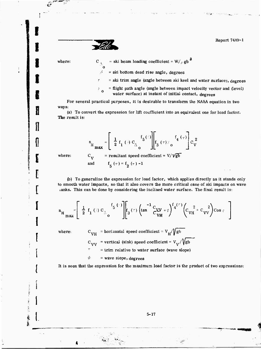
#
' ^W ■.:--■■■ ■..,-._
I I I I I i I 0 0 I I [
I
Report 7489-1
where: C - ski beam loading coefficient - W/^ gb o
p = ski bottom dead rise angle, degrees
T = ski trim angle (angle between ski keel and water surface;, degrees
> = flight path angle (angle between impact velocity vector and (level) water surface) at instant of initial contact, degrees
For several practical purposes, it is desirable to transform the NASA equation in two ways:
(a) To convert the expression for lift coefficient into an equivalent one for load factor. The result is:
H max
1 f5(f)
1 fl < > CA o
f3(T,io
'4(r)
^v2
where: C = resultant speed coefficient - V/l/gb"
and f5 (r)=f2 {T)-i
(b) To generalize the expression for load factor, which applies directly as it stands only to smooth water impacts, so that it also covers the more critical case of ski impacts on wave tanks. This can be done by considering the inclined water surface. The final result is:
n H
max
1 f5 < >
o f3^
(tan ^pQJ +r4
\ CVH ^ 4 lCVH + CVV ,C0S
i 1
where: C = horizontal speed coefficient = V /1/gb
Cvv = vertical (sink) speed coefficient = V /ygb
= trim relative to water surface (wave slope)
<# = wave slope, degrees
It is seen that the expression for the maximum load factor is the product of two expressions:
I I 5-17
i^ * ., V«—

Y •^..' : Y-:. . .*-. .... _ ■ ... . ^ ^ ^^ t' ;
I I r
Report 7489-1
( i" One involving only tae two basic ski parameters: beam loading and dead rise;
(b) One involving a combinationof the three so-called "approach parameters" (trim relative to water surface and the two aircraft velocity components) and the wave slope angle.
Because of its inherently quantitative nature, this impact load factor equation will be treated more fully in the final Phase II report for this project. It will suffice here to point out tnat, in addition to furnishing accurate numerical values for the maximum impact loads, the formu'a also serves to indicate the relative effects of the various parameters.
(See Bibliography Entry Numbers: (9), (17), (28), (30), (34), (37), (38), (39), (40), (41), (42), (44), (45), (46), (49), (64), (66), (67), (73), (75), (80), (94), (98), (117), (120), (121), (125), (HO), (143), (145), (146), (148), (149), (160), (161), (170), (174). (176), (180), (181), (185), (187), (191), (192), (193).)
5.3.2 Bovr Submergence
It will be noted that the maximum impact load formula does not account for the length of the ski, that is, it assumes that the hydro-ski bow is still above the water surface when the maximum impact load is developed. It is evident, then, that the maximum impact load formula does not cover those cases in which the ski length limits the magnitude of load developed.
As a check on the applicability of the maximum impact equation for specific ski de- sign and specific impact conditions, the hydrodynamic loaa developed at the instant of bow submergence can be calculated by use of the equivalent planing velocity associated with the initial approach conditions of the impact. (See Section 5.4. 3.) If this calculation results in a higher load than that given by the maximum impact formula, the maximum impact formula is applicable. If this calculation results in a lower load than that from the maximum impact formula, the maximum impact formula is presumably inapplicable because bow submergence is limiting the load developed. It should be noted also that the result of the equivalent planing velocity calculation is slightly conservative, since it assumes a constant velocity impact.
(See Bibliography Entry Numbers: (9), (30), (35), (174), (176).)
5.3.3 Stem Taper
Stern taper in the hydro-ski planform has the effect of causing the hydrodynamic load to build up more gradually during the initial stage of the impact process, than it would with a square transom. It can be expected therefore that, for the same initial approach condition, a hydro-ski with a tapered stern will develop less impact load than the same ski without stern taper. The validity of this hypothesis has only been demonstrated in element tests for hyro-skis of very low beam loading coefficient. Full-scale flight tests of a high beam loading hydro-ski seaplane showed no load alleviation effect introduced by stern taper.
5-18
ay , - f- 7 •*■■

i
I I
i
[
[
[
L I I
Report 74H9-1
Tank tests of a moderate beam loading coefficient (8. 5) hydro-ski on a model j aircraft indicated that, although stern taper resulted in smoother landings, no significant ^ ! Jj load reductions were obtained. Pending further verification, stem taper appears to have no
noticeable effect on the maximum impact load of hydro-skis having practical beam loading coefficients.
(See Bibliography Entry Numbers: (1), (14). (i-7), (49). (174).)
5.3.4 Shock Absorbers
Incorporation of a hydraulic shock absorber into the hydro-ski support strut (or struts) provides a means for achieving even further reduction in impact loads. Model and prototype tests have proven the feasibility of such a combination when applied to hydro-skis of moderate beam loading coefficients. Shock absorber application is not indicated for hydro- skis of high beam loading coefficient, since the beam loading effect alone is capable of pro-
f, ducing practical minimum impact load factors.
Although attractive for some hydro-ski installations because of its potential addi- tional load alleviation, it must be kept in mind that a shock absorber may be the source of other difficulties, as described in paragraph 4. 3. 3.
No simple formula exists for estimating the effect of a shock absorber in a specific impact. However, a simplified calculation procedure is available for rapid determination of the effect of including a shock absorber as part of a hydro-ski installation.
(See Bibliography Entry Numbers: (14), (20), (21), (23). (24), (28), (29), (32), (60), (74), (94). (96), (142), (152), (153), (155), (157). (160). (170). (174).)
5. 3. 5 Yaw and Roll
For structural and hydrodynamic purposes, hydro-ski impact calculations are usually performed with the assumption that no yaw or roll effects are present. However, it is apparent that these factors should be considered in the structural design of certain components. For example, the torque induced during a yawed landing may be a critical item for the hydro- ski support strut design.
Although, yawed and/or rolled hydro-ski impact data are presently non-existent, information is available on the hydrodynamic characteristics of yawed and rolled planing sur- faces. As the load developed at any time during a hydro-ski impact is essentially equal to
I the hydrodynamic load at the instantaneous equivalent planing velocity (see Section 5. 4. 3), the v. effects of yaw and roll on impact loads can presumably be taken into account for engineering
design purposes, if desired.
(See Bibliography Entry Numbers (46), (69).)
y 5-19
, I*--
J'

^ tl
I I T
Report 7489-1
YfA
5.3.6 Waves
Since the hydro-ski has demonstrated that it is most advantageous in functioning as a load alleviation device during rough water operations, a thorough understanding of wave effects on impact behavior is desirable. For this purpose it is best to consider a hydro-ski impacting in calm water, and an inclined water surface representing the flank of a single wave. This action is illustrated in the following sketch:
WAVE
It can be seen that, for the same values of horizontal speed V , sink speed V , H v
and trim, T , with respect to the horizon, impacting on an inclined water surface (wave flank) only changes the effective forward speed V., , by a slight amount but causes a significant re-
duction in effective trim, T , and a significant increase in effective sink speed, V . e
The NASA maximum impact formula described above shows that, for other than shallow flight path angles, hydro-ski trim is not an important factor in determining the magnitude of the maximum hydrodynamic impact load. Consequently, the principal cause of increase in impact load when contacting a wave is the increase in effective sink speed which, according to the NASA formula, is a primary maximum impact load parameter.
(See Bibliography Entry Numbers: (9), (15), (23), (28), (30), (35), (44), (64), (67), (94), (96), (102), (104), (117), (120), (125), (142). (143), (145), (146), (148), (149), (161). (173), (174), (176), (180), (181), (185). (187). (191). (192), (193).)
5-20
i if ii mnnfrii
/

-«r
I -«=HaE5«e:»»s !^K«s»e--•>*■»■ .■^S^-" -r ■ '-^-«.-- /.^^ .- ^^^^^jj^^-'.-^ji,!;--,»---.»-r ■- '- -4» "" =;T'"'"ET 5r
i I i i i B 0 0 0
! F ! 0
[
1:
i. i
I
Report 74«9-l
5. 3.7 Wing Uft
In the preceding discussions on maximum impact load, it has been tacitly assumed that no gravitational effects influenced the hydro-ski during the impact process. This is equivalent to considering that the aircraft is experiencing a constant velocity descent at impact, by virtue of the wing lift being equal to the aircraft weight. Although the wing Uft of a landing aircraft is usually quite close to the 100% value usually assumed, it is apparent that during a take-off, after unporting but prior to getaway, wing lift will be considerably less than 1007 of the aircraft weight.
Impact calculations have been performed which indicate that, as compared with the 100*4 wing lift case, the maximum hydrodynamic impact load for the zero wing lift case, is only 24 percent higher for a hydro-ski, whereas the comparable increase for a hull is 62 percent. Moreover, under these same conditions, the hull seaplane inertia acceleration in- creased by 15 percent, while the hydro-ski seaplane inertia acceleration decreased by 23 percent. These results, based on impact theory, indicate another specific reason for the superiority of the hydro-ski seaplane over a conventional seaplane.
(See Bibliography Entry Numbers: (117), (174).)
5. 4 HYDRO-SKI PRFSSLT.E DISTRIBUTION
The pressure distributions associated with the hydrodynamic loads on a hydro-ski are of interest to the structural designer, since a knowledge of the center of pressure only is inadequate for complete definition of the local conditions of normal loading, shear, and bending moment. However, as a hydro-ski is essentially a relatively narrow beam structure, normal pressures are of little interest. Skin panel thickness and dimensions are usually such that consideration need not be given to plating failure due to normal loading. Nevertheless, the pressure distribution is needed in order to determine the longitudinal running load, from which shear and bending moment diagrams may be derived.
3.4.1 Submerged Hydro-Skis
A submerged hydro-ski may operate in a variety of flow regimes, depending on the specific circumstances, so that, corresponding pressure distributions will also vary with the flow regime.
At low speeds, fully wetted flow will exist and, although the pressure distribution may be estimated from low aspect ratio subsonic aerodynamic data, these pressures are of little concern because of their low magnitudes.
As the speed increases, the hydro-ski will either cavitate or ventilate, again de- pending on specific circumstances. In either case, the upper surface of the hydro-ski will be subjected to a gas pressure; that is, water vapor pressure in cavity flow or atmospheric
5-21

I I T
Report 7489-1
YOA
pressure in ventilated flow. It is this latter flow condition which is of most concern to the structural designer because it necessarily occurs at getaway and landing speeds which are the critical conditions for maximum impact loads.
5.4.2 Surfaced Hydro-Skis
A partially submerged hydro-ski will, of course, experience bottom pressures only over the wetted portion of its length. The magnitude and distribution of the bottom pressure acting on a planing hydro-ski may be readily determined from available data.
in general, the pressure distribution on the bottom of a planing surface is similar in shape to that on the lower surface of an airfoil, having relatively high positive pressure for- ward and lower pressure aft. However, the peak pressure on a planing surface is associated with the stagnation point location, which is in the vicinity of the hydro-ski intersection with the water surface, rather than near the ski leading edge.
As the stagnation flow streamline is below the free water surface streamline, the water strata above the stagnation streamline are thrust forward by the hydro-ski in the form of heavy spray. The water below the stagnation streamline tends to flow around the side edges of the hydro-ski. The following sketch will serve to clarify these statements.
STAGNATION STREAMLINE
STAGNATION POINT
I . / ^— PRESSURE DISTRIBUTION
1/ /
ROACH -
vi^
!
5.4.3 Impact-Planing Relation
It has been previously mentioned that, pressure distribution data are available for planing hydro-skis, thpt is, for the case where the resultant velocity is parallel to the water sarface. However, the more severe impact condition is the one pertinent to structural de- sign purposes.
Theoretical and test results have established that, for an impacting hydro-ski, both the load and the pressure distribution developed are equivalent to those for a planing hydro-ski
5-22
fifes' if^4-
■ -»..-.-wi-r^y»«- y.-».^- ..—U^.'.-
"4 .--•'. ^ '

■*?
f ♦•^w
n
i f E 0 fl 0
f]
Report 7489-1
having the same velocity component normal to the keel. This "equivalent planing velocity concept" is of fundamental importance in determining the hydrod>„amic load acting on a hydro- ski at any instant during the impact process The following sketch illustrates the impact- planing relationship:
where: 'r = trim angle
7 = flight path angle
R resultant velocity
V -- velocity normal to keel
V = equivalent planing velocity
Now vXT = V sin ^ = V„ sin ( y + r ) N p R
[ [
[ >
i C
■ L
Hence, a hydro-ski impacting at trim angle, r , at an instantaneous resultant velocity, V , and flight path angle, 7 , will have the same hydrodvnamic characteristics
R (pressure distribution, lift coefficient, etc.) as a hydro-ski planing at the same trim and a velocity equal to:
V sin ( y + T ) V = -^ :
p sin T
It must be emphasized that the equivalent planing velocity concept is valid only for a hydro-ski intersecting the water surface. Once the leading edge of the hydro-ski has sub- merged, the hydrodynamic characteristics are those of a submerged surface of velocity, V , and angle of attack, a - T
+ y
(See Bibliography Entry Numbers: (9), (14), (28), (29), (39), (41), (42), (44), (46), (49), (57), (73), (146), (153). (174), (183).)
I r i L 5-23

[ Report 7489-1
Y(fA
5. 3 UNSYMMETRICAL LOADINGS
Unsymmetrical loadings that may be developed during hydro-ski seaplane operations are of interest and concern in connection with structural design and aircraft stability. Un- symmetrical loadings are most likely to occur in crosswind operations and, depending on the longitudinal location of the hydro-ski and strut, also when the ski submerges in the later portions of a landing runout.
5.5.1.1
Unsymmetrical Hydro-Ski Loadings
Hydro-Ski Submerged
Unsymmetrical loadings for submerged hydro-skis, when the skis are fully wetted at low speeds, are of little interest. The reason is that greater loads may be readily developed at higher speeds, for example, when the ski penetrates the water surface during a yawed landing, and only the bottom surface is wetted. Further, even at high speeds, where high beam loading skis may be submerged, it is unlikely that the unsymmetrical loads acting on a submerged hydro-ski will exceed those for a surfaced hydro-ski with complete bottom wetting. This can be explained by the loading characteristics of an impacting hydro-ski in which the maximum load occurs at the instant of complete bottom wetting. For this case, immediately after bow submergence, there is a sharp drop in the hydrodynamic load as the ski is now in the region where the equivalent planing velocity concept is no longer valid (see Paragraph 5.3.2).
5. 5.1.2 Hydro-Ski Planing
V» « rrJ i-«<"» _ C L' ■ It has just been indicated that the maximum unsymmetrical leading of will occur when it is in the surfaced condition during the course of an impact, It is indeed fortunate that this is so, for it leads to a relatively simple rational approach to the estimation of design unsymmetrical loading values.
As previously discussed, the instantaneous hydrodynamic load developed during an impact may be related to the load corresjwnding to the pure planing condition by means of the equivnlpnt planing velocity concept. Also, towing tank data are available for the hydro- dynamic characteristics in unsymmetrical planing conditions. Consequently, using such data, the previously described impact-planing relationship ma3- be applied to the calculation of unsymmetrical hydro-ski design load values..
(See Bibliography Entry Numbers: (46), (69), (114), (128), (143), (144), (150), (154), (156), (183), (191), (192), (193).)
5.5.2 Unsymmetrical Strut Loads
The magnitude of the lateral load developed on a fully submerged hydro-ski strut when the aircraft is in a yawed attitut ia of vital concern to the hydro-ski designer. Aside
5-24
•*m*'-%
^■■ !.-•*-,

w t-
i
i 'T
*--<
Report 7489-1
from the obvious relation to structural design, strut side loads strongly influence the aircraft directional and lateral stability during take-off and landing.
Longitudinal stability requirements dictate that the hydro-ski and strut be located somewhat forward of the aircraft center of gravity so that the resultant hydrodynamic ski load passes through or very close to, the c. g. However, it is apparent that, with the strut so located, hydrodynamic side loads on the strut will induce a destabilizing yawing moment, as well as a rolling moment on the aircraft. The ability to estimate unsymmetrical loads on the hydro-ski strut permits an evalua ion of directional and iaterai stability and control with strut immersed and aircraft yawed.
(See Bibliography Entry Numbers: (86), (114). (115), (126), (128), (183), (191), (192), (197).)
3.5.2.1 Fully Wetted Strut
Fully wetted flow can exist on a streamlined strut having a sharp trailing edge, and on a base-vented strut of blunt trailing edge. For the latter case, however, the term is meant to apply to the situation wnere both sides are fully wetted. This type of flow is usually associated with low angles of yaw. Side loadings for sides fully wetted can be determined from applicable towing tank data and/or aerodynamic data.
5.5.2.2 Ventilated Strut
As the angle of yaw and speed increases, cavitation and/or ventilation will occur on one side of the strut. When this happens there is a sudden reduction in the force coefficient and lift curve slope, since the hydrodynamic pressure now acts on one side only. Even with this alleviating feature, strut side forces under yaw in ventilated flow are of significance in stability considerations. Theoretical and towing tank results are available for calculation of strut side forces in ventilated flow. The most difficult aspect of such estimates is the determination of the angle of yaw for which the flow changes from fully wetted to venti- lated, since no method now exists which adequately permits the prediction of ventilation in- ception, either theoretically or through scaling of towing tank results.
5.6 HULL IMPACT LOADS
5. 6.1 Effects of Hydro-Ski Installation
A hyuxu-ski installation may be regarded as a shield which protects the seaplane hull bottom against severe water impact conditions. However, it is obvious that the hull bottom of a hydro-ski equipped seaplane will still experience water impacts even though they will be much lighter than those experienced without the ski. It follows that, for efficient structural design of the hull of hydro-ski seaplanes, it is necessary to be able to estimate the magnitude of hull impact loads.
5-25
*
!
r
Tut.
V .> i
^ t--
Report 7489-1
Stated in slightly different language, efficient hull design requires hull structural loading criteria which rationally account for the presence of the hydro-ski. For example, use of the existing loading criteria for conventional seaplane hulls would obviously be unduly con- servative and provide the ski-equipped seaplane with excessive structural weight, thus eliminating a fundamental advantage inherent in the hydro-ski installation.
It is unfortunate that such rational hull structural loading criteria for hydro-ski seaplanes have not yet been developed. This makes it necessary for the designer to investi- gate the pertinent towing tank and full-scale test data and, through suitable interpretation, to apply these results to his particular configuration. To make matters worse, the amount of pertinent test data is distinctly limited and, often, difficult to interpret. For example, it might be expected that the acceleration recordings obtained in the towing tank tests of dynamic models could be used for this purpose. Experience has shown that, particularly at intermediate speeds in waves, these recordings must be very carefully analyzed in conjunction with the pitch and heave records to ascertain clearly whether a particular impact occurred on the hull or on the ski. A similar statement applies to many full-scale flight test instrumentation records.
This difficulty has been eliminated, however, in the most recent full-scale tests of hydro-ski seaplanes by use of more definitive instrumentation. In this case, a set of strain gauges are used to "isolate" both ski and strut loads from the total aircraft accelerations thus permitting readier determination of hull impact loads.
In view of these circumstances, the following discussions of hull impact loads are largely of a descriptive nature.
5. 6.2 Take-off in Smooth Water and Waves
It is evident that hull impact loads need not be considered for take-offs conducted in relatively calm water. Under this condition, the hull is only subjected to relatively light hydrodynamic pressures and total loads.
In rough water take-offs, the situation is completely different. In this case, particu- larly in the unporting speed range, the hull forebody bottom can easily impact against a wave surface. Although significant, hull bottom design loadings will be considerably lower than those for a comparable conventional seaplane because unporting speeds are appreciably lower than getaway (take-off) speeds.
It can be anticipated that a hull designed for a penetrating hydro-ski installation will be subjected to larger bottom loads than one designed for a lower beam loading hydro-ski installation. This conclusion results from a consideration of the behavior in waves of each type of hydro-ski installation on struts of the same length. Following unporting, the small, penetrating type hydro-ski, having a more limited load development capability, will tend to "plow through" waves so that high hull impacts can occur. A larger hydro-ski, having a greater load development capability, will tend to rise over the waves and keep the hull clear. It is thus apparent that the hydro-ski size is intimately related to hull bottom structural design,
(See Bibliography Entry Number: (130).)
5-26
!
$, 4 iTTSr

^*egfp- zog^c f--^':---T.!vsg,:
fl
i I I
i i I I [
Report 7489-1
rai
5.6. 3 Landing in Smooth Water and Waves
Hull impact characteristics for a hydro-ski seaplane during landing are similar to, yet somewhat different from those described for take-off. One obviously similar feature is that the effect of rough water is to increase the probability of hull impacts, the probability increasing with decreasing hydro-ski size.
On the other hand, if a high sink speed, low trim landing is made with a penetrating hydro-ski seaplane, hull impact may occur because the hydrodynamic load developed on the ski is Insufficient to overcome the aircraft vertical momentum within the available strut length.
5. 6.4
(See Bibliography Entry Numbers: (15), (23), (35), (130), (146).)
Hull Loading Criteria
In view of the present lack of rational structural design criteria for hydro-ski seaplane hulls, only very brief and tentative suggestions for suitable approaches can be made at this time.
Subject to further detailed studies, it appears that basic guidance in this problem area may be obtained from the structural design procedures currently being developed for the hulls of hydrofoil boats which employ submerged foils. The fundamental concept for such hulls covers a condition in which the boat is running foilbome at maximum speed in its maximum design sea state. In this condition, it is supposed that all forward (or, alternately all aft) foils are subject to a catastrophic failure, i. e. , for purpose of calculation; they are considered to disappear. The resulting unbalance results in the crashing of the hull forebody (alternately, stern) into the water and, for conservatism, it is further assumed that the impact occurs on the flank of an incoming wave. This design impact condition is used as the basis for impact history calculation using the hull geometry and applicable impact theory (virtual mass. expanding plate, etc.) to obtain local pressures, total loads, load centroids, etc.
A similar approach for the hydro-ski seaplane would involve a "hull crashing" condition while planing in rough water. Because this approach is entirely novel, it appears necessary to investigate several combinations of speeds, initial aircraft trims, and engine power settings to establish the most critical design conditions for the various portions of the hull.
For military aircraft applications this approach might be viewed as being too con- servative, so that an alternate rational criterion should also be considered, such as the hull contacting a wave while ski-borne. For large hydro-skis it seems reasonable to design the hull for wave impacts at the unporting speed, while, for penetrating hydro-skis, some speed between unporting and take-off would be used.
5-27
^J *». 0

-T N;riae>jag--
I I I I
Report 7489-1
?^J
6. HYDRO-SKI SEAPLANE PERFORMANCE CHARACTERISTICS
This section discusses those characteristics which have been found to be of fundamental importance in the appreciation of hydro-ski seaplane performance qualities. A similar dis- cussion of stability and control characteristics is given in Section 7 of this report.
(For General Performance Characteristics, See Bibliography Entry Numbers: (22), (92), (93). (94), (97), (100), (101), (102), (103), (107), (109), (134), (158), (159), (160), (161), (167), (169), (170), (173), (175), (177), (184), (187), (190), (191), (192), (193).)
6.1 UNPORTING SPEED
The unporting speed is, by definition, the speed at which the hydro-ski emerges and represents that speed above which the hull may be considered to have only minor influence on behavior of a hydro-ski seaplane. For a conventional seaplane, the hull is the source of the behavior and load problems occurring in rough water. It follows that, if no other problems were involved, the hull of a hydro-ski seaplane should be raised out of the water at the lowest possible speed.
For the same airplane, a practical sized low beam loading hydro-ski will give a lower unporting speed than a smaller, high beam loading hydro-ski. Therefore, the heavier, low beam loading hydro-ski results in lower hull impact loads than the lighter high beam loading hydro-ski. Furthermore, improved aerodynamic control is achieved with an increase in unporting speeds. The choice of unporting speed is therefore one of the fundamental quantities that must be considered in the establishment of hydro-ski size.
6.2 UNPORTING/TAKE-OFF SPEED RATIO
Of greater performance significance, than the absolute value of the unporting speed, is the ratio of unporting to take-ofi speed. Although the total dynamic force acting on a hydro-ski seaplane results from both water and air flow about the lifting surfaces, control- ability is obtained only from the aerodynamic surfaces. * Clearly then, the unporting - take- off speed ratio, is indicative of the degree to which the pilot can control the aircraft attitude either to minimize resistance lor improved take-off performance or, to counteract destabilizing effects inherent in the hydro-ski configuration.
Unless it has unusual inherent stability characteristics, a hydro-ski seaplane with a low ratio of unporting to take-off speed will generally require skillful piloting to achieve succe.sslui
I
I
!
* The hydro-ski trailing edge flap, described elsewhere in this report, represents the only attempt made, thus far, to utilize hydrodynamic controls in a hydro-ski seaplane.
6-1
/• .^ >■-■.'

-.•^M ,.-.,aw»™s.,a.--.i-Jn(r--i* • :^'WISM«^-'«Jo»s»'''oftaa^ya»«gjJ.-»a«9cy.
i
E fl
I I i B 0 0
0 I L
I
[ [
[
Report 7489-1
unporting because of the "sluggish" or non-existent response to aerodynamic control move- ments. This problem diminishes with increasing unporting/take-off speed ratio but, on the other hand, hull load alleviation effectiveness will be reduced as this ratio approaches unity.
6. 3 UNPORTING TRIM
The maximum trim angle during the unporting process has an important bearing on the performance acceptability during take-off. High unporting trims are undesirable because of the associated poor spray and high resistance characteristics. However, it is immediately recognized that the hydrodynamic lift force generated by the hydro-ski, as required to effect unporting, is partly accomplished by means of increasing trim.
For the relatively large, low beam loading hydro-skis, where unporting inherently occurs at speeds below which aerodynamic controls are effective, the pilot may have little or no capability to minimize unporting spray and drag. However, in the case of a penetrating hydro-ski type, with its higher unporting/take-off speed ratio, the pilot can, by increasing unporting speed, maintain moic moderate trim angles during unporting and thereby improve spray and resistance performance.
6.4 UNPORTING SPRAY
The spray generated by a hydro-ski during unporting has proven to be one of the most critical problem areas. There have been occasions where huge quantities of spray were thrown up and practically enveloped the entire aircraft. Aside from the obvious visual discomfort to the pilot, the take-off performance appreciably suffered because of the reduced thrust and propeller erosion caused by spray.
I •* The hydro-ski configuration designer must pay particular attention to design details affecting spray performance since experience has shown that towing tank tests do not completely simulate prototype spray. As mentioned elsewhere, this lack of similarity is caused largely by the yaw and roll constraints normally applied to a tow tank model.
(See Bibliography Entry Numbers: (1), (5), (8), (15), (22), (27), (72), (81), (92), (97), (100), (102), (103), (107), (122), (158), (161), (173), (177), (184).)
6.5 RESISTANCE
6. 5.1 Smooth Water f" '- The calm water resistance, particularly in the unporting speed region, materially
influences the take-off time. A hydro-ski installation on conventional hull seaplanes generally |j increases the hump resistance and tends to deteriorate take-off performance. For this reason,
it may be desirable to design a hull take-off capability into an operational hydro-ski seaplane, Cby incorporating retractable hydro-skis. This approach may not be necessary however,
since future seaplanes will likely have adequate thrust and high aerodynamic lift at low speeds.
6-2

;> -
T. I I
PS'- ■ >^ss=s, j .-»srs^^*,.
- \ ■
Report 7489-1
mm"
Should the hull configuration be such that the hydro-ski is necessarily also extended for smooth water take-off, reiinements contributing to drag reduction should be thoroughly considered. A small reduction in hump drag, where excess thrust is at a minimum, can re- sult in a significant improvement in take-off time.
6.5.2 Rough Water
In wave conditions not severe enough to induce excessive pitching motions, the rough water resistance of a hydro-ski seaplane is of less concern than its calm water resis- tance. This aspect of hydro-ski seaplane performance, as previously discussed, is primarily caused by favorable wind effects, including the direct effect of increasing wing lift and the in- direct effect of increasing fhe aerodynamic control available to the pilot. However, with a further increase in sea state, the resistance rises again primarily because of the increase in angular motions. Of course, if the hydro-ski seaplane configuration is such that the ski is ex- tended for rough water operations only, the resistance under these conditions must be properly accounted for in performance estimates. !
6.6 TAKE-OFF TIME |
6.6.1 Smooth Water I
i
The calm water take-off time is, of course, a fundamental parameter in seaplane a performance evaluation. For a hydro-ski modification of a hull seaplane having good excess | thrust margins, take-off time improvement as compared with the basic seaplane performance, | has been recorded even though the hump drag was increased. This improvement however, J rapidly diminishes with lower excess thrust margins, so that it may not be generally claimed & as an inherent advantage of a hydro-ski seaplane. %
(See Bibliography Entry Numbers: (8), (22), (91), (92), (97), (100), (101), (107), (160). (161). (173), (184), (191). (196).)
6.6.2 Rough Water
Tike-off time is, of course, directly related to resistance. Therefore, previous comments on rough water resistance are, in u^tuality, applicable to the rough water take-off time; thus no further discussion is needed.
6.7 SKI-STRUT VIBRATIONS
As revealed by flight tests the structural flexibility of a hydro-ski installation may be the source of ski-strut vibration response problems if not adequately considered during the design phase. To date, the analvtical studies conducted during the development of hydro- ski configurations have been concerned only with the more basic design parameters and treat the hydro-ski aircraft combination as a rigid body (except for shock-absorber, ii any). More- over, the geometrically similar models used in the towing tank program usually scale to a
6-3
^m»

w.-is^^* -; "K^Kk^
n r i i
Report 7489-1
much higher structural stiffness than the prototype. In this sense, past full-scale hydro-ski flight tests have been conducted on relatively flexible vehicles for which the effects of structural flexibility on hydrodynamic characteristics have not been previously evaluated.
The current seaplane strength and rigidity specification requires that the dynamic response of the structure, including structural flexibility, be determined for the loadings developed in rough water take-offs and landings. Presumably then, in future hyöro-ski sea- plane programs, most of the structural dynamic response problems will be uncovered in the design phase, rather than during the full scale performance evaluation. It is the intent of this section to review the experience in ski-strut vibrations, and thereby point out the need for
investigitions of the associated phenomena, so that projected hydro-ski seaplanes may avoid this potential problem area.
6.7.1 Wave Impact Response
A single impact on a hydro-ski installation induces a transient and vibratory motion which, ordinarily, will not be of significance in comparison to the rigid body response. How- ever, under some conditions, when planing in choppy water, where the hydro-ski impacts can occur in rapid succession, a resonant response may result which tends to magnify the loads and motions. As yet, no catastrophic performance has been attributed to this condition. Nevertheless, it is also an admitted possibility, so that, in view of the potentially serious consequences of its occurrence, the design analysis should investigate this behavioral mode.
(See Bibliography Entry Numbers: (22). (96), (100), (101), (158), (159), (161), (166), (179). (182).)
6. 7. 2 Hydroelastic Effects
In one full-scale hydro-ski installation, hydroelastically-induced, violent lateral ski-strut vibrations occurred prior to unporting at long strut extensions. As a result, operating this prototype hydro-ski configuration had to be at a somewhat smaller strut ex- tension than the one indicated by the tow tank tests. It is therefore desirable that this phenom- enon be investigated during the design ;:' ise of a hydro-ski seaplane, in order that pei'formance expectations, as related to strut length, be realized.
The cause of this unsatisfactory behavior appears to have been the resonant response of the ski-strut structure to the lateral forces induced by an asymmetric periodic flow phenomenon ("vortex ventilation") developed on the hydro-ski or strut at a particular combination of speed, depth ^aid trim. In view of the complex nature of this phenomenon, it may be necessary to rely on towing tank procedures to explore the possibility of its occurrence on a prototype hydro-ski configuration.
Another hydroelastic phenomenon of interest is the self-excited hydroelastic vibra- tions which have been found (in tow tank tests) to occur on large wetted aspect ratio, flexible planing surfaces. The initial studies of this effect were motivated by their potential
6-4
4 fc-;,f . «>-,.„
-,'-j- f# i'.

' ^Ms; x«^ t r
I l
Report 7489-1 Y(4k
applicability to hydro-skis. However, the theory successfully explaining this effect shows that the conditions leading to this behavior, (exceptionally calm water, high wetted aspect ratio and ski flexibility) do not usually apply to conventional ski design and/or full-scale hydro-ski seaplane operation. Accordingly, it is considered that this mode of vibration is not of practical concern to the hydro-ski designer.
(See Bibliography Entry Numbers: (26), (77), (87), (104), (177), (191), (192), (193), (195).)
6. 8 HIGH SPEED TAXIING
In addition to its load-alleviating characteristics in seaplane take-offs and landings, a hydro-ski installation also contributes toward a more comfortable ride during high-siieed planing. Consequently, unlike conventional seaplane operations, where the hull bottom pound- ing during planing produces much noise and vibration, there will be a greater tendency for pilots to utilize a hydro-ski seaplane in high speed taxiing conditions.
High speed planing performance is primarily concerned with turning maneuverability. Single hydro-ski installations are distinctly superior to twin hydro-skis in this respect be- cause twin skis are inherently resistive to banking of the aircraft. Further, because of their flat turn characteristics, twin skis exhibit greater skidding tendencies.
(See Bibliography Entry Numbers: (24), (60), (74), (95), (96), (97), (100), (102), (104), (138), (169), (190).)
6-5

.->■
fi
s
f I I I I I
II
! i I
V f
I [ I
II
i [
; [
•^S»«-""-?5-'.--r^.
Report 7489-1
7. HYDRO-SKI SEAPLANE STABILITY AND CONTROL CHARACTERISTICS
The stability and control characteristics of a hydro-ski seaplane configuration are fundamental to the successful performance of the vehicle. Although this design aspect is of equal importance in hull type seap'anes, the problems are generally much more severe for hydro-ski seaplanes. This is caused primarily by the fact that the hydro-ski configuration must undergo a stability critical unporting process, which has no counterpart in hull seaplane operations. Also, the hydro-ski and strut arrangement itself contributes certain destabilizing effects; these will now be clarified.
| i 7.1 LONGITUDINAL
Experience has shown that, with rare exceptions, the stability and control problems associated with the longitudinal (primarily heaving and pitching) motions of the hydro-ski sea- plane are far more critical than those associated with the directional and lateral (primarily yawing and rolling) motions. Whereas the directional and lateral problems sometimes result in additional demands on the pilot's skill and efforts, they are generally not insurmountable. On the other hand, an unsatisfactory ski installation can result in longitudinal problems which render the aircraft completely unsatisfactory, and even uncontrollable under certain operational conditions. Consequently, while establishing an arrangement primarily on the basis of longitu- dinal considerations, the hydro-ski designer will also bear in mind those aspects of the design which influence yaw and roll stability, in order that the aircraft also be acceptable in these respects.
(See Bibliography Entry Numbers: (22), (27), (30), (31), (32), (33), (52), (55), (61), (62), (77), (92). (93), (97). (99), (100), (101), (102), (103), (104). (106), (107), (109), (111), (116), (120), (122), (125.1. (128), (131), (136), (137), (139), (142). (145), (147), (151), (155), (158), (159), (160), (161), (163). (167), (169), (170), (172), (173). (175). (177), (178), (ISO), (181), (182), (184). (185), (188). (189). (190). (191). (192). (193), (196).)
7.1.1 Pre-unporting Regime
At low speeds, and prior to the initiation of the unporting action, no longitudinal stability problems are anticipated. The bow-down moment resulting from the hydro-ski and strut drag, is compensated by the bow-up moment developed by the dynamic lift for a proper- ly located hydro-ski. In general, in this speed range, the trim and rise of a hydro-ski sea- plane will be moderately higher than that of a comparable hull seaplane. Furthermore, observational impressions indicate that,in the pre-unporting range, the aircraft pitching oscillations in rough water are damped by the hydrodynamic forces developed on the hydro-ski.
7.1.2 Unporting
[In take-off, the first speed region critical for longitudinal stability is at the initiation of hydro-ski unporting where the combination of increasing trim and approach to the free sur- face causes flow separation from the upper surface of the hydro-ski. Such flow separation
7-3
t_ i».
I I I
Report 7489-1
or "cavity formation", if occurring as an integral feature of the unporting process can give rise to an undesirable condition of "emergence instability", this phenomena will now be ex- plained.
If the unporting speed is sufficiently low (typically, for low beam loading skis), this flow separation is usually caused by ventilation whereby the top of the ski is vented to the atmosphere. Furthermore, inception of this ventilation may be caused by aeration of the skis' tip vortices or by downward extension of the aeration cavity associated with the surface-piercing ski support strut. At high unporting speeds, typical of very high beam loading skis on large aircraft, flow separation can also occur through inception of cavitation on the ski itself or through the spreading of strut cavitation. These flow phenomena are further complicated by certain effects directly associated with the ski,s low aspect ratio. Aside from the ski and strut geometry, the particular prevailing (steady state) flow regime is dependent on speed, ski trim, and ski depth. It may be mentioned that the relations and boundaries between these various flow regimes, together with corresponding ski loads, have been quite thoroughly investigated in towing tank tests using combinations of struts and (in- dependently) practical ski shapes and idealized skis (low aspect ratio flat plates).
Despite the detailed complexities of these flow processes, the fundamental aspects of the "emergence instability" problem can be explained in terms of basic hydrodynamic theory, as follows:
For given values of speed, trim (angle of attack), and with a fixed reference area, the lift force acting on a dynamic lifting surface (wing, foil, ski, etc.) of a given aspect ratio depends on its "two-dimensional lift curve slope. " This quantity, in turn, depends on the nature of the flow around the surface's cross-section, as shown by the following set of (theoretical) values: n
FLOW La (THEOR.)
(rad."1)
Fully Wetted 2^7
Ventilated (Submerged) w/2
Fully Cavitated (Submerged) 7T/2
Planing 7T
Here, the ventilated and fully cavitated conditions differ from one another only in the pressure on the upper surface, i.e., atmospheric pressure (ventilated) and water vapor pressure (cavitated).
During unporting and irrespective of the particular type of cavity created, if the flow about the ski changes suddenly from a fully wetted condition to a cavity condition (ventilated or fully cavitated), this change will be accompanied by an equally sudden and very m.irked re- duction in the ski lift, tending to make the ski resubmerge. In general, ♦Ms "force-break" effect is more pronounced at low unporting speeds where the ski lift ad balance the major portion of the aircraft weight.
7-2

#
'^ -i_4
I G I I I
0 0
c
[ [
c i
: [
Report 7489-1
On the other hand, if the ski unporting speed is so great that the (submerged) ski is in a substantially ventilated or even fully eavitated condition prior to its unporting, the unporting process is actually accompanied by an increase of ski lift,tending to guarantee the complete absence of any resubmergence possibility.
This fundamental difference between the low and high speed unporting dynamics of hydro-ski installations has been fully confirmed both in towing tank and full-scale flight tests. Moreover, noting that, for a given seaplane, the unporting speed is directly dependent on the ski beam loading, it follows that high beam loading skis (generally) have an additional desirable feature in that they directly eliminate the possibility of this "ski emergence instability."
Historically, the emergence instability problem was first encountered in towing tank tests of low beam loading skis where it manifested itself particularly in a porpoising behavior of the model during runs made at constant speed at, or close to, the unporting speed. However, further tank tests, later verified in full-scale tests, showed that such porpoising did not exist in accelerated take-off tests made with realistic acceleration values. Despite this fact, emergence instability has been encountered in full-scale flight tests. In this case, in spite of the (idverse) low speeds involved, the pilot's elevator control proved more than adequate to eliminate the instability. It was only necessary to maintain a forward yoke position in the initial portion of the take-off run to obtain a somewhat lower trim angle at unporting. * The resulting increased unporting speed was then adequate to eliminate the instability.
With the current emphasis on high beam loading skis, emergence instability may be regarded as a completely '. isignificant problem area. A force-break occurrence will have less effect, and more important, aerodynamic control and damping forces are greater, all of which help to contribute to stable action. It should also be mentioned that, in at least one case, in- creasing acceleration was found to deteriorate the emergence stability. It is believed that this phenomenon is attributable to a low value of aerodynamic damping.
If, for the moment, attention is solely confined to the hydro-ski, and, as is likely, the hydro-ski is in a cavity flow regime on approaching the water surface, the transition from
I submerged to planing will be made stable. Such behavior is predicated on the absence of I factors causing excessive trim reduction and, thus, a loss of planing lift and consequent re-
submergence. The basic reason for this lies in the realm of fundamental hydrodynamics. The | lift in cavity flow, where only the full bottom area is wetted, is about one-half of what it would
be in the planing condition with the same wetted area, a phenomenon which can be explained by the nature of the flow around the leading edge in each case. Stated simply, the theoretical
| lift-slope of a two dimensional submerged flat plate in cavity flow is ^/2, while it is TT in the planing condition.
♦ Note that this technique is completely opposite to standard flight procedures for conventional seaplanes and also to natural piloting instinct.
7-3
4 4 1

Jt I
I I T
Report 7489-1 mir
It is further indicated that emergence instability is strongly influenced by the de- tailed nature of the transient water flow processes which occur in hydro-ski broaching. Pri- mary among these are the spray characteristics developed when the hydro-ski bow pierces the water surface at high trim and velocity. If a heavy spray reaches critical regions of the air- craft, such as the engines or tail surfaces, thrust may be reduced and/or diving moments developed, either of which effects can cause an unstable condition. Dynamic model tow tank tests are considered mandatory to ensure that the full-scale configuration will be free of (uncontrollable) ski emergence instability.
(See Bibliography Entry Numbers: (7), (12), (27), (77), (92), (93), (97), (100). (102), (103), (104), (106), (107), (135), (163), (181), (190)
7.1.3 Post-Unporting
Following the unporting process, the hydro-ski remains in the planing condition throughout the rp->ainder of the take-off run. In this post-unporting regime, the hydro-ski seaplane may encounter the same types of longitudinal instability present in conventional hull seaplanes, i.e., so-called low-angle and high-angle porpoising conditions. Furthermore, with conventional seaplanes, the fundamental criterion relating to these instabilities is the existence, at any given speed, of a large practical trim range between the two porpoising "boundaries. " A further criterion is that the low-angle porpoising trim limit must be sufficiently low so as not to impair the seaplane's hydrodynamic resistance either directly through trim effects or, indirectly, through deleterious spray affects.
7.1. 3.1 Low-Angle Porpoising
Similar to an aircraft in flight, a seaplane planing in smooth water at constant speed and trim under equilibrium conditions may be dynamically unstable. By this it is meant that, if the seaplane is displaced from its equilibrium speed-attitude condition by a small amount, the aerodynamic and hydrodynamic forces and moments generated by the dis- placement are such that the ensuing seaplane motions consist of a series of oscillations whose magnitudes increase exponentially with time. This type of behavior may be contrasted with that corresponding to an equilibr i condition which is dynamically stable, in which the sea- plane motions following a disturbance consist either of a "subsidence" (non-oscillatory, damped motion) or, of a damped oscillation.
In the case of the planing seaplane (either hull or hydro-ski types) dynamic insta- bility manifests itself in the following manner. At a fixed planing speed and at a particular trim, the airplane is (let us say) dynamically stable in the preceding sense. The airplane may then be re-trimmed at a lower trim angle, through elevator control and required throttle adjustment, so that the orisinal speed is maintained. If this process is continued with small decreases in speed at each step, a particular trim angle (lower trim stability limit) will be reached at which the aircraft will have lost its dynamic stability (i. e., its capability for damping oscillations) and become "neutrally stable". Whereas, theoretically, this neutral stability condition is considered as a sharp boundary between stable and unstable behavior.
7-4

■ v
- .••»
ö 0
I I I ii
fl
0
Report 7489-1
it actually manifests itself as a narrow region in which oscillations can maintain a finite amplitude. In practice, the boundary is defined as the trim angle at which these sustained neutral oscillations have a double amplitude of 2 degrees. Further decrease of the equilibrium trim angle then results in a genuine dynamic instability. The seaplane modes of oscillation significant in this instability behavior are heaving and pitching while the associated surging motions are usually very small and thus, have little effect on the stability trim limit.
While many hydro-ski installations exhibit this type of instability with sufficient reduction in trim, it has been found, for the most part, that the associated trim stability limits neither affect the operation of the airplane nor result in excessive rpsistance or adverse spray characteristics. More specifically, in those cases involving the addition of a hydro-ski to an existing hull seaplane, this addition usually had no adverse effect on the low trim stability limits.
However, in one case involving towing tank tests of a small ski installation, the lower trim limits were found to be excessively high and, further, these limits could not be improved by the usual devices of reasonable shifts of the aircraft e.g. and/or the ski longi- tudinal location.
It is important to note that the problem of lower limit porpoising has only been investigated on an "ad hoc" basis in the development of working configurations of specific ski installations and, equivalently, no experimental or analytical parametric studies have been made of this important problem area. Although never explicitly demonstrated by such studies, it appears that, just as with hull-type seaplanes, the aerodynamic characteristics of the hydro-ski seaplane have a basic effect on the low trim stability limits.
7.1. 3.2 High-Angle Porpoising
In the conventional seaplane, high speed planing at high trims is often accompanied by a "roach" or "rooster tail" in the wake of the hull. This phenomenon is the direct result of the transformation of the kinetic energy, imparted to the water mostly in the stagnation portion of the wetted hull bottom and being transformed into the potential energy of an elevated water surface. Depending on a number of configuration factors, this "roach" may be that high and that close to the planing surface (hull forebody) that it wets a portion of the hull afterbody. Aside from the obviously undesirable nature of this condition from the resistance standpoint, it is perhaps even more undesirable because is can also obviously lead to the class of unstable oscillations labeled high angle porpoising. These oscillations, primarily involving trim changes, may be considered to involve a resonance between the aircraft's natural pitching frequency (as determined by aerodynamic and hydrodynamic characteristics) and the "applied" frequency associated with the unsteady forces generated by the "roach" motion relative to the afterbody.
[
!
I 1 I I
In the case of the hydro-ski seaplane operating at a comparable high speed and high trim, the "roach", assuch,is often more severe, i.e. , it is higher and closer to the ski. However, in most hydro-ski installations, these effects are more than compensated by the
7-5
*'* '-«MMMIH]

.,w®ms
I [ V/tA
vertical distance of the ski below the afterbody keel, so that the "roach" does not reach the afterbody. For such installations, the net effect of the ski is beneficial, i.e., the upper trim stability limits are raised. Vice versa, there have been cases where these stability limits were lowered because of a too low effective strut length. It follows that high angle porpoising is a problem area requiring specific investigation in the tow tank test phase of hydro-ski development particularly in those cases where, for any reason, short strut lengths are under consideration.
(See Bibliography Entry Numbers: (5), (8), (10), (12), (22), (27), (31), (33), (100), (101), (103), (104), (109), (111), (151), (158), (159), (160), (163), (169), (172), (185).)
7.1.4 Touchdown
The longitudinal stability at touchdown is dependent on the magnitude of the moment about the aircraft center of gravity caused by the impacting hydro-ski. If the hydro-ski is too far forward, an excessive pitch-up motion will occur. Vice versa, diving will take place if the hydro-ski is too far aft.
Towing tank model tests have been conducted which relate the optimum hydro-ski location to the value of beam loading coefficient. As the hydro-ski beam loading is increased, the further forward it must be located in order to prevent diving. Furthermore, with pene- trating type hydro-skis, low trim landings are also conducive to diving. These effects are to be expected, since both high beam loading and low trims imply impacts with ski submergence, strut wetting and thus, relatively high drag component. In such cases, the resultant inclined force developed on the hydro-ski and strut tends to produce a bow-down motion of the aircraft unless the ski is located sufficiently far forward.
7.1.5 Ski Submergence
i During the landing runout, a speed is reached at which the hydro-ski can no longer I
be maintained in the surface planing condition. (In general, because of different power settings, this landing ski submergence speed differs from the take-off ski importing speed.) For large, low beam loading hydro-skis, there is little possibility of longitudinal instability as the air- craft settles down on the hull because the ski submergence speed is relatively low and also be- cause of the high longitudinal deceleration.
In the case of smaller penetrating hydro-skis, the comparable submergence speed is somewhat higher. However, if the ski has been properly located in towing tank tests, there will be no uncontrollable pitching motions induced, so that, here also, longitudinal stability on ski submergence is not expected to be a problem area, twr has it been on full scale tests). 7.2 DIRECTIONAL
A hydro-ski seaplane configuration is usually established with the aid of towing tank tests where the model is restrained against roll and yaw motions. Therefore, although
7-6

K
0 I I i i 0 0
i i
ü [
[
I I
I I I
Y/Zt Report 7489-1
longitudinal stability requirements may have been satisfied, the subjects of directional and lateral stability remain to lie investigated to ensure proper prototype performance. This section will first consider the stability characteristics associated with angles of yaw.
(See Bibliography Entry Numbers: (5), (12), (15), (22), (92), (93), (97), (100), (101), (102), (103), (104), (106), (107), (109), (147), (151), (158), (161), (167), (169), (170),
073). 075), (177), (182), (184), (185), (190), (192). 093). )
7.2.1 Pre-unporting Regime
Longitudinal stability considerations have been shown to be of prime importance in determining the fore-and aft location of the hydro-ski installation. The typical hydro-ski arrangement will be established, from tan^- tests, somewhere forward of the aircraft center of gravity. On this account, any hydrodynamic yawing moments and/or side forces developed by the hydro-ski and strut are obviously directionally destabilizing.
Directional stability prior to unporting has been found to be one of the most critical areas in operating full-scale hydro-ski aircraft. Because of the relatively forward position
ff of the hydro-ski and strut, it is evident that the severity of a directional stability problem is directly related to the strut length. It follows that, for the same basic aircraft at the same speed with strut fully wetted, a oenetrating hydro-ski installation, with its naturally longer and further forward strut, may be more critical with respect to pre-unporting directional stability than the large hydro-ski installations. However, since a large hydro-ski contributes a significant portion ofthe side force and yawing moment developed by an immersed ski-strut combination, it is possible that, even with the further forward location of the strut, pre- unporting directional stability of a penetrating hydro-ski installation will not be more critical.
Fortunately, the aircraft yawing rates associated with directional instability at pre-unporting speeds are relatively slow. Consequently, if the pilot has control available for applying restoring movements, the yaw motion in the pre-unporting range can he kepi within tolerable limits. For some aircraft configurations, particularly multi-enfjwied p;-J-
peller driven aircraft, yaw control is readily available by means of asymmetrical thrust and possible rudder sMp-stream effects. As i corollary, a single engine jet aircraft could easily be deficient in this oontr n mode, in which caso it might be necessary to prr/ide a water rudder control. It is also seen that a shock absorber strut supported hydro-ski may be beneficial in this connection since mechanical means may then be employed to maintain a shortened strut up to the time unporting action begins.
7.2.2 Unporting. Post-unporting. and Touchdown
Once unporting action begins, wherein the hull forebody and hydro-ski emerge, directional stability and control characteristics rapidly improve to the point where no special pilot skill is required through take-off. During crosswind landings, however, excessive sideslip angle at the instant of touchdown must be avoided. A touchdown at too high a sideslip angle may cause a rapid, uncontrollable yaw response.
7-7
'■.,-

■ifrr:
t
I r Report 7489-1
war
7.2.3 Ski Submergence
After touchdown, hydro-ski planing is maintained until the velocity has dropped to the point where the ski can no longer be kept on the surface. The speed at which this occurs is dependent upon the hydro-ski size, and is relatively lower for the larger type skis.
With ski submergence and consequent strut wetting, there is usually a tendency for the aircraft to water loop as the hull settles down. This tendency is caused by the destabilizing influence of any inadvertent side loads acting on the strut. Because of the low velocity and high deceleration for configurations with large type hydro-skis, the hooking at ski submergence results only in momentary crew discomfort, with "datively little probability of damage to the aircraft. However, for a penetrating hydro-ski aircraft, ski submergence occurs at a relatively high speed. Further, as the strut is in a more forward position because of longi- tudinal stability considerations, hooking induced by ski submergence can, in these circum- stances, cause serious consequences, and needs to be closely examined during the hydro- dynamic design phase.
However, there are certain mitigating features which tend to reduce, but not elimin- ate, the possibility of catastrophic behavior. In the first place, because of the comparably higher ski submergence speeds of penetrating hydro-ski aircraft, aerodynamic control may be adequate to permit effective pilot action in suppressing yaw instability. Secondly, because of the high speeds, small yaw angles may result in strut ventilation with wetting on one side only, so that the strut side force is much less than that which would occur with both strut sides wetted. Thus, while directional instability at ski submergence may be a problem area, it is not necessarily an insurmountable problem.
7.3 LATERAL
Although treated as a separate item, the lateral stability and control of hydro-ski aircraft operating at the air-water interface are in most cases integrally related to the directional stability characteristics. This is easily appreciated from the fact that a side load in the vicinity of the hydro-ski and strut combination can be expected to induce relatively large net rolling moments of high effectivity.
(See Bibliography Entry Numbers: (5), (12), (22), (92), (93), (97), (100), (101), (102), (103), (104). (106), (107), (147), (158), (159), (161), (167), (169), (170), (175), (177), (184), (191), (192), (196).)
7.3.1 Pre-unporting Regime
For the most part, those effects tending to contribute to directional instability prior to importing are also detrimental to lateral stability. Consequently, except for the longitudinal position of ski and strut, those hydro-ski installation design features which are beneficial for directional stability prior to unporting are also advantageous from a lateral stability viewpoint.
7-8
f
/

.•<-r"
I
r [ [ r r.
[
■!;
Report 7489-1
f There is, however, one operational parameter which has a primary effect on lateral stability, namely, cross-wind. At low speeds, any seaplane in a cross-wind, will tend to
I maintain a rolled attitude because of the wind act1' i on the wings. At low speed, proper heading with respect to the wind is more critical for a hydro-ski seaplane because of the need to initiate the importing action with the airplane horizontal. In the case of propeller
f aircraft, and provided that the wind is not too severe or gusiy, this can be accomplished by skillTul application 01 engine power throughout the pre-unporting speed range, thus utilizing the righting effect of propeller torque to level the aircraft while turning into the wind.
7.3.2 Unporting
The unporting regime is usually most critical with respect to the lateral stability of a hydro-ski seaplane. The prototype aircraft behavior in this mode is usually unpredictable prior to full-scale flight tests, as take-off tests in the towing tank are usually conducted with the model restrained in roll. Furthermore, even if yaw-induced hydrodynamic rolling mo- ments are measured, their significance is of questionable validity, because of the unknown scale effects on cavitation and/or ventilation.
As mentioned previously, wind direction must be taken into account in order to minimize rolling tendencies during unporting. If unporting occurs at too low a speed, adequate aerodynamic restoring control moments are not available to the pilot. Here again, the hydro-ski configuration is of significance to the stability of the aircraft.
Twin ski configurations have been investigated as an approach to solving the unporting lateral stability problem more or less inherent in the single large hydro-ski. A qualitative comparison of these two configurations indicated that the twin hydro-ski lateral stability characteristics during unporting are superior to those of a single hydro-ski configuration. This statement however, should not be interpreted to mean that a twin ski configuration can not be laterally unstable at unporting. Flight tests have shown that, if unporting was attempted with excessive heel, there is a tendency for only one ski to surface, with the associated high drag preventing the additional speed increase required to unport the other ski. However, suitable piloting technique for the approach to the unporting condition, as already indicated, proved adequate in practice to overcome this tendency.
Lateral instability problems at unporting are considerably less severe for a con- '. |- figuration utilizing a penetrating type hydro-ski. Since, for this case, unporting is at a I I, comparatively high speed, aileron control is usually adequate to prevent an excessive heel
angle.
7. 3. 3 Post-unporting, and Touchdown
The comments made on this subject of directional stability in these regimes apply equally to the roll characteristics.
7-9
rfi^l^^'^^Vj^J
V J,

EP, ■■■ r->
.«»WH' ^>'<r"-.,rr^ ^«T:^»* ■ -* ■■
I I
Report 7489-1
VV5J
7.3.4 Ski Submergence
Lateral instability at ski submergence is not considered to be a critical problem area. The process of settling down on the hull inherently limits the roll angle that may be developed assuming, of course, that adequate hydrostatic roll control devicas (wing tip floats, hull sponsors, etc.) are present.
I
7-10
fa.'

■*r
r T Report 7489-1
YftA
8. BIBUOGRAPHY OF HYDRO-SKI TECHNOLOGY
NATIONAL AERONAUTICS AND SPACE ADMINISTRATION (NACA)
1. RM L7104 "Preliminary Tank Tests of NACA Hydro-Skis for High-S^eed Air- planes, " by John R. Daw son and Kenneth L. Wadlin, November 26, 1947.
2. RM L8B18 "Tank Si>ray Tests of a Jet-Powered Model Fitted with NACA Hydro- Skis," by Kenneth L. Wadlin and John A. Ramsen, 1948.
3. RM L9B10a "The Effect of Rear Chine Strips on the Take-Off Characteristics of a High-J^)eed Airplane Fitted with NACA Hydro-Skis," by John A. Ramsen, March 17, 1949.
4. RM L9C03 "Planing Characteristics of Three Surfaces Representative of Hydro- Ski Forms, " by Kenneth L. Wadlin and John P.. McGehee, March 29, 1949.
5. RM L9K29 "Tank Investigation of the Grumman JRF-5 Airplane Fitted with Hydro- Skis Suitable for Operation on Water, Snow, and Ice," by Kenneth L. Wadlin and John A. Ramsen, June 12, 1950.
6. RM L9L20 "Planing Characteristics of Six Surfaces Representative of Hydro-Ski Forms," by Kenneth L. Wadlin and John R. McGehee, February' 10, 1950.
7. RM LÖ1E21 "Tank Investigation of the Grumman JRF-5 Airphuie with a Single Hydro-Ski and an Extended Afterbody," by John A. Ramsen and George R. Gray, August 7, 1951.
8. RM SL51F07a "Hydrodynamic Investigation of a l/13-Scale Model of the Consolidated Vultee Skate 7 Seaplane Equipped with Twin Hydro-Skis." by Robert E. McKann. Claude W. Coffee, and Donald D. Arabian, November 7, 1951.
9. RM L51F27 "Water Landing Investigation of a Hydro-Ski Model at Beam Loadings of 18.9 and 4.4," by Sidney A. Batterson, September 12, 1951.
10. RM SL51I24 "Tank Investigation of the Edo Model 142 Hydro-Ski Research Airplane, " by John A. Ramsen, Kenneth L. Wadlin, and George R. Gray, September 24, 1951.
11. RM L52B28 "Force Characteristics in the Submerged and Planing Condition of a 1/5,78-Scale Model of a Hydro-Ski Wheel Combination for the Grumman JRF-5 Air- plane," by Norman S. Land and Charles A, Pelz, July 11, 1952.
8-1
■- -^■*.-,;*^^iiefca.
*;•% A- • T JTi

I I
4& ^-
Report 7489-1
Y&i II
12. RM SL52D17 "Tank Investigation of the Grumman JRF-5 Airplane Equipped with Twin Hydro-Skis, " by John A. Ramsen and George R. Gray, April 10, 1952.
13. RM LÖ2H15 "Preliminary Tank Tests of some Hydro-Ski-Wheel Combinations in the Planing Condition, " by Norman 8. Land and Rudolph E. Fontana, October 6, 1952.
14. RM L53D29 "Estimation of Water Landing Loads on Hydro-Ski-Equipped Aircraft," by Emanuel Schnitzer, July 17, 1953.
15. HM L53FÖ4 "A Brief Hydrodynamic Investigation of a Navy Seaplane Design Equipped with a Hydro-Ski, " by Uoyd J. Fisher and Edward L. Hoffman, September 1, 1953.
16. RM L53I28b "Considerations Affecting Hydro-Ski Airplane Design, " by Kenneth L. Wadlin, November 17, 1953.
17. RM L53K20a "Comparison of Experimental Hydrodynamic Impact Loads and Motions for a V-Step and a Transverse-Step Hydro-Ski, " by Robert W. Miller, February 2, 1954.
18. RM SL54A28 "Investigation of the Hydrodynamic Characteristics of the Panto-Base Chase C-123 Airplane, " by William C. Thompson and Lloyd J. Fisher, 1954.
19. RM L54F01 "The Hydrodynamic Planing Lift of Four Surfaces as Measured in a 200-FPS Free Jet, " by John R. McGehee, Bernard Weinflash, and Charles A. Pelz. July 7, 1954.
20. RM SL54G30 "Comparison of Shock-Absorber installations on the Panto-Base Chase C-123 Airplane in Rough-Water Landings, " by William C. Thompson and Lloyd J. Fisher, July 27, 1954.
21. RM L54H10 "Water-Impact Theory for Aircraft Equipped with Nontrimming Hydro- Skis Mounted on Shock Struts, " by Emanuel Schnitzer, October 18, 1954. (Superseded by Bibliography Entry Number 71).
22. RM 54J27 "Some Results of Flight Testing of 'jki-Equipped Aircraft at The Naval Air Test Center, " by Preston E. Beck, February i, 1955.
23. RM L54L02 "Model Investigation of the Effect of Mounting Hydro-Skis on Shock Absorbers," by Edward L. Hoffman and Lloyd J. Fisher, March 1, 1955.
24. RM L55E09b "Reduction of Hydrodynamic Impact Loads tor Waterborne Aircraft, " by Emanuel Schnitzer, July 6, 1955.
-i
8-2
z %

r r i
i 11
i
Report 7489-1
25. RM L55G29a "A Comparison of the Hydrodynamic Forces on 1/25-, 1/10-, and 8/10-Size Models of a Convair XF2Y-1 Hydro-Ski, •■ by Ellis E. McBride. October 7, 1955.
26. RM L55J27 "Preliminary Investigation of Self-Excited Vibrations of Single Planing Surfaces," by Elmo J. Mottard, January 20, 1956.
27. RM SL55L15 "Tank Tests of a l/8-Size Powered Dynamic Model of the Martin PBM-5 Seaplane Equipped with a Single Edo Hydro-Ski," by Claude W. Coffee Jr., January 6, 1956.
28. RM Li56D26 "Comparison with Theory of Landing Impacts of a Model of a Seaplane Incorporating a Hydro-Ski with and without a Shock Absorber, " by Edward L. Hoffman, July 11, 1956.
I 29. RM L56E31 "Theoretical Determination of Water Loads on Pitching Hulls and s' Shock-Mounted Hydro-Skis, " by Emanual Schnitzer, October 19, 1956.
I I -j I 30. RM L56I25a "Tank Investigation of a Series of Related Hydro-Skis as Load-Allevi-
ation Devices for Landing a Seaplane in Waves, " by Arthur W. Carter, Archibald E. Morse, Jr., and David R. Woodward, December 19, 1956.
31. RM L57G05 "Aerodynamic and HydrocK namic Characteristics of a Proposed Super- sonic Multijet Water-Based Hydro-Ski Aircraft with a Variable-Incidence Wing, " by William W. Petynia, Dennis F. Hasson, and Stanley H. S^ooner, October 23, 1957.
32. RM L58A22 "Preliminary Investigation of Land-Water Operation with a 1/10 Scale Model of a Jet Airplane Equipped with Hydro-Skis. " by William C. Thompson, March 1*, 1958.
33. Memo 1C-13-58L "Low-Speed Aerodynamic and Hydrodynamic Characteristics of a Proposed Supersonic Multijet Water-Based Hydro-Ski Aircraft with Upward- Rotating Engines," by William W. Petynia, Delwin R. Croom, and Edwin E. Davenport. October 1958.
34. Memo 1-5-59L "The Effect of Beam Loading on Water Impact Loads and Motions," by John S. Mixson, February 1959.
35. Memo 1-9-59L "Hydrodynamic Impact-Load Alleviation with a Penetrating Hydro-Ski, " by Philip M. Edge, Jr. , February 1959.
36. Memo 1-25-59L "Effect of Convex Longitudinal Curvature on the Planing Characteristics of a Surface without Dead Rise, " by Elmo J. Mottard, February 1959.
8-3
t« J - »^

! y&A
L
j V, Report 7489-1 |l {
;
37. Memo 2-10-59L "A Generalized Hydrodynamic-lmpact Theory for the Loads and Motions of Deeply Immersed Prismatic Bodies." by Melvin F. Markey, March 1959.
38. TN 2015 "Water Landing Investigation of a Model having a Heavy Beam Loading and a 30° Angle of Dead Rise," by Sidney A. Batterson and A. Etbelda McArver, February 1950.
39. TN 2111 "A Study of Water Pressure Distributions during Landings with Special Reference to a Prismatic Model having a Heavy Beam Loading and a 30° Angle of Dead Rise, " by Robert F. Smiley, July 1950.
40. TN 2330 "Water-Landing Investigation of a Model having Heavy Beam Loadings and 0° Angle of Dead Rise," by A, Ethelda McArver, April 1951.
•i
41. TN2453 "An Experimental Study of Water-Pressure Distributions during Landings and Planing of a Heavily Loaded Rectangular Flat-Plate Model." by Robert F. Smiley, September 1951.
42. TN 2583 "A Semiempirical Procedure for Computing the Water-Pressure Distribution on Flat and V-Bottom Prismatic Surfaces during Impart or Planing," by Robert F. Smiley, December 1951. |
■fi
43. TN 2804 "The Planing Characteristics of a Surface having a Basic Angle of • Dead Rise of 20° and Horizontal Chine Flare," by Walter J. Kapryan and Irving Weinstein, October 1952. |
44. TN 2813 "Theory and Procedure for Determining Loads and Motions in Chine- Immersed Hydrodynamic Impacts of Prismatic Bodies," by Emanuel Schnitzer, November 1952. i
45. TN 2814 "The Application of Planing Characteristics to the Calculation of the Water-Landing Loads and Motions of Seaplanes of Arbitrary Constant Cross Section. " | by Robert F. Smiley, November 1952.
46. TN 2817 "A Theoretical and Experimental Investigation of the Effects of Yaw- on Pressures, Forces, and Moments during Seaplane Landings and Planing, " by Robert F. Smiley, November 1952.
47. TN 2842 "The Planing Characteristics of a Surface having a Basic Angle of Dead rise of 40° and Horizontal Chine Flare," by Ulysse J. Blanchard, December 1952.
48. TN 2876 "The Planing Characteristics of Two V-Shaped Prismatic Surfaces having Angles of Deadrise of 20° and 40", " by Der rill B. Chambliss and George M. Boyd, Jr., January 1953.
8-4
K

r n i i
i i :
?
■ P
I i I ' I
[
I I I
Report 7469-1
49.
50.
51.
52.
53.
54.
oo.
56.
57.
58.
59.
60.
TN 2932 "Water-Landing Investigation of a Flat-Bottom V-Step Model and Comparison with a Theory Incorporating Planing Data," by Robert W. Miller, May 1953.
TN 2981 "The High-Si)eed Planing Characteristics of a Rectangular Flat Plate over a Wide Range of Trim and Wetted Length, " by Irving Weinstein and Walter J. Kapryan, July 1953.
TN 3052 "The Effect of Vertical Chine Strips on the Planing Characteristics of V-Shaped Prismatic Surfaces having Angles of Dead Rise of 20° and 40% " by Walter J. Kapryan and George M. Boyd, Jr., November 1953.
TN 3079 "The Hydrodynamic Characteristics of Modified Rectangular Flat Plates having Aspect Ratios of 1.00 and 0.25 and Operating Near a Free Water Surface, " by Kenneth L. Wadlin, John A. Ramsen, and Victor L. Vaughan, Jr., March 1954.
TN 3092 "Hydrodynamic Drag of 12- and 21-Percent-Thick Surface-Piercing Struts," by Claude W. Coffee, Jr. , and Robert E. McKann, December 1953.
TN 3233 "A Review of Planing Theory and Experiment with a Theoretical Study of Pure-Planing Lift of Rectangular Flat Plates, " by Charles L. Shuford, Jr,, August 1954.
TN 3249 "The Hydrodynamic Characteristics of an Aspect-Ratio -0.125 Modi- fied Rectangular Flat Plate Operating Near a Free Water Surface," by John A. Ramsen and Victor L. Vaughan, Jr.. October 1954.
TN 3420 "Hydrodynamic Tares and Interference Effects for a 12-Percent-Thick Surface-Piercing Strut and an Aspect-Ratio -0. 25 Lifting Surface, " John A. Ramsen and Victor L. Vaughan, Jr., April 1955.
TN 3477 "Hydrodynamic Pressure Distributions obtained during a Planing Investigation of Five Related Prismatic Surfaces.' by Walter J. Kapryan and George M. Boyd, Jr. , June 1955.
TN 3615 "An Experimental Investigation of the Scale Relations for the Impinging Water Spray Generated by a Planing Surface, " by Ellis E. McBride, February 1956.
TN 3642 "Effect of Shallow Water on the Hydrodynamic Characteristics of a Flat-Bottom Planing Surface, " Kenneth W. Christopher, April 1956.
TN 3803 "Band-Pass Shock and Vibration Absorbers for Application to Aircraft Landing Gear, " by Emanuel Schnitzer, October 1956.
8-5

Report 74*9-1
WM'
61. TN 3903 "An Experimental Hydrodynamic Investigation of the Inception of Vortex Ventilation," by John A. Ramsen, April 1957.
62. TN 3908 "Hydrodynamic Characteristics over a Range of Speeds up to 80 Feet Per Second of a Rectangular Modified Flat Plate having an Aspect Ratio of 0. 25 and Operating at Several Depths of Submersion," by Victor L. Vaughan, Jr., and John A. Ramsen, April 1957.
63. TN 3939 "A Theoretical and Experimental Study of Planing Surfaces Including Effects of Cross Section and Plan Form, " by Charles L. Shuford, Jr., March 1957.
64 TN 3940 "Impact-Loads Investigation of Chine-Immersed Models having Con- cave-Convex Transverse Shape and Straight or Curved Keel Lines," by Philip M. Edge, Jr., February 1957.
65. TN 3951 "Investigation of the Planing lift of a Flat Plate at Speeds up to 170 Feet Per Second," by Kenneth W. Christopher, March 1957.
66. TN 4103 "Impact-Loads Investigation of Chine-Immersed Model having a Cir- cular-Arc Transverse Shape. " by Philip M. Edge, Jr., September 1957.
67. TN 4123 "Rough-Water Impact-Load Investigation of a Chine-Immersed V-Bottom Model having a Dead Rise Angle of 10°," by Melvin F. Markey and Thomas D. Carpini, October 1957.
68. TN 4168 "A Method for Calculation of Hydrodynamic Lift for Submerged and Planing Rectangular Lifting Surfaces," by Kenneth L. Wadlin and Kenneth \V.
69. TN 4187 "High-Speed Hydrodynamic Characteristics of a Flat Plate and 20 Dead Rise Surface in Unsymmetrical Planing Conditions," by Daniel Savitsky, R. E. Prowse, and D. H. Lueders, June 1958.
70. TN 4251 "An Experimental Investigation of Wake Effects on Hydro-Skis. " by Ellis E. McBride and Lloyd J. Fisher, May 1958.
71. TN 4256 "Water-Impact Theory for Aircraft Equipped with Nontrimming Hydro- Skis Mounted on Shock Struts," by Emanuel Schnitzer, September 1958 (Supersedes Bibliography Entry Number 21.)
72. TN 4294 "Effects of Nose Shape and Spray Control Strips on Emergence and Planing Spray of Hydro-Ski Models, " by John R. McGehee, July 1958.
8-6
H >
- Christopher, January 1958. 4
.
^ ^ llMRm ——..- ;-.-.s^-:_——»™—f-iii ■^..-, ii , .„ „, ^
♦

I) II D I i
i n n
i" I 0 I -r 1 c
[
[
[
[
Report 7489-1
f •
73. TN 4339 "Hydrodynamic Impact Loads of a -20" Dead-Rise Inverted-V Model and Comparisons with Loads of a Flat-Bottom Model, " by Philip M. Edge, Jr., August 1958.
74. TN 4387 "Experimental Evaluation of a Low-Band-Pass Landing-Gear Shock Absorber for Pulse Loadings, " by Emanuel Schnitzer, September 1958.
75. TN 4401 "Hydrodynamic Impact Loads on 30° and 60° V-Step Plan-Form Models with and without Dead Rise," by Philip M. Edge, Jr., and Jean P. Mason, September 1958.
76. (Paper) "Ventilated Flows with Hydrofoils, " by Kenneth L. Wadlin, NACA, Paper presented at Twelfth General Meeting of the American Towing Tank Conference, University of California, August 1959.
77. TN D-51 "The Hydrodynamic Characteristics of a Submerged Lifting Surface having a Shape Suitable for Hydro-Ski Application, " by Victor L. Vaughan, Jr., October 1959.
78. TN D-166 "A Hydrodynamic Investigation of the Effect of Adding Upper-Surface Camber to a Submerged Flat Plate, " by Victor L. Vaughan, Jr., November 1959.
79. TN D-180 "Hydrodynamic Characteristics of a Planing Surface with Convex Longitudinal Curvature and an Angle of Dead Rise of 20°, " by Elmo J. Mottard, January 1960.
80. TN D-207 "Hydrodynamic Impact-Loads Investigation of Chine-Immersed 0 Dead Rise Configurations having Longitudinal Curvature; with an Appended Bibliography of Langley Basin Hydrodynamic Publications, " by Robert W, Miller. February 1960.
81. TN D-220 "A Brief Investigation of a Hydro-Ski Stabilized Hydrofoil System on a Model of a Twin-Engine Amphibian, " by Sandy M. Stubbs and Edward L. Hoffman. February 1960.
NAVY DEPARTMENT: DAVID TAYLOR MODEL BASIN
82. Report 920 "The Planing Characteristics of a V-Shaped Prismatic Surface with 50 Degrees Dead Rise," by George B. Springston, Jr. and Clifford L, Sayre, Jr., February 1955.
83. Report 1076 "The Planing Characteristics of an Inverted V Prismatic Surface with Minus 10 Degrees Dead Rise," by Peter M. Kimon, March 1957.
8-7

pt
T
I Report 7489-1
8-8
f
84. Report 1285 "The Planing Characteristics of a V-Shaped Prismatic Surface with 70 Degrees Dead Rise," by James D. Pope, Ltjg., USN, December 1958.
85. Report D1490 "Stepless and Stepped Planing Hulls - Graphs for Performance Predic- tion and Design," by Eugene P, Clement and James D. Pope, Ltjg., USN, January 1961.
86. Report 1778 "Experimental Measurements of the Steady Lift, Drag, and Moment y on Surface-Piercing Struts," by Gene M. Wilburn and H. Smith Malier, Jr., October 1965.
87. Report 2017 "Investigation of Self-Excited Planing Vibration at Large Wetted ' Aspect Ratio," by E. J. Mottard, November 1965.
NAVAL AIR SYSTEMS COMMAND: f
DESIGN-RESEARCH DIVISION
88. D. R. Report 1043 "An Empirical Study of Low Aspect Ratio Lifting Surfaces with Particular Regard to Planing Craft," by F. W. S. Locke, Jr., January 1948.
89. D. R. Report 1143 "A Rough Method for Estimating the Unporting Characteristics of Hydro-Ski Equipped Seaplanes," by F. W. S. Locke, Jr. , August 1949.
90. D. R. Report 1274 "Preliminary Analysis of the Drag Characteristics of Hydro- foil Struts," by F. W. S. Locke, Jr., March 1951.
i 91. Report R-5-60-19 "A Review of the Hydrodynamics of Rough Water Seaplanes. "
by F. W. S. Locke, Jr. , December 1960.
NAVAL AIR TEST CENTER: i PATUXENT RIVER. MARYLAND f
92. PTR DE-324 FT32-048 "Single Hydro-Ski Installed on a JRF-3 Airplane. Hydrodynamic Evaluation of. Letter Report No. 1," April 4, 1952.
i
93. PTR DE-324 FT32-0108 "Project TED No. PTR DE-324, Single Hydro-Ski i Installed on a JRF-5 Airplane, Hydrodynamic Evaluation of, Letter Report No. 2," July 22, 1952.
94. PTR DE-324 FT32-041 "Project TED No. PTR DE-324, Hydrodynamic Evaluation of a Single Hydro-Ski Installed on a JRF-5 Airplane, Letter Report No. 3, Final Report," March 20. 1953.

wr
I P
0
0
0 0
n o r
i:
Report 74H9-1
YfA
95. PTR DE-320 FT32-050 "Evaluation of All American Airways, Inc., Universal Ski Alighting Gear, " April 8, 1952.
96. PTR AD-320 "Tests of SNJ-5C Airplane, Bu. No. 51925, Equipped with Universal Sei Alighting Gear, Letter Report No. 2, Final Report, " November 2, 1953.
97. PTR AD-341 "Hydrodynamic Evaluation of Twin Hydro-Skis Installed on a Model JRF-5 Airplane, Letter Report No. 1, " December 8, 1953.
98. PTR AD-341 "Hydrodynamic Evaluation of Twin Hydro-Skis Installed on Model JRF-5 Airplane Buno 37805, Letter Report No. 2, Final Report, " January 27, 1956.
99. PTR AC-64002 "Evaluation of a Model OE-1 Airplane Equipped with Universal Ski Alighting Gear, Letter Report No. 1," December 28, 1953.
100. PTR AC-25102-1 "Preliminary Evaluation of Model XF2Y-1 and YF2Y-1 Air- planes, Letter Report No. 2, Final Report, " June 3, 1955.
101. PTR AC-25103.1 "Brief Re-Evaluation of Hydrodynamic Characteristics of Model XF2Y-1 Airplane, Letter Report No. 1, Final Report, " November 28, 1955.
102. PTR AD-366 "Model PBM-5S2 Hydro-Ski Airplane, Evaluation of Hydrodynamic Characteristics, Report No. 1, " October 31, 1956.
103. PTR AD-366.1 "Evaluation of Hydrodynamic Characteristics of Model PBM-5S2 Airplane with a Modified Hydro-Ski, Report No. 1, Final Report, " March 25. 1938.
104. PTR AD-366. 2 "Evaluation of Hydrodynamic Characteristics of Model PBM-3S2 Airplane with a Small Variable Area Hydro-Ski, Report No. 1. Final Report," September 25, 1061.
105. Report FT2121-35R-65 "Final Report Evaluation of the Hydrodynamic Characteristics of the JRF-5G Hydrofoil Seaplane, " by LCDR Nicholas J. Vagianos. Mr. William B. Rhodes, July 21, 1965.
106. Report FT-rt3R-65 "Evaluation of Hydrodynamic Characteristics of a Hydro-Ski Seaplane; Final Report, " December 6, 1965.
AIR FORCE: AIR MATERIEL COMMAND
107. MCREOA-4/JMH/ay "Development of Hydro-Skis and Pantobase Aircraft." January 31, 1950.
8-9
_i L

?T
4/.
Report 7489-1
yftA
AIR RESEARCH AND DEVELOPMENT COMMAND
10b. "Pantabase Aircraft, " January 1, 1953.
WRIGHT AIR DEVELOPMENT CENTER
109. WADC Technical Note 57-23 "Evaluation of a Hydroski Installation on the YC-123E Pantobase Aircraft, " by Captain Robert L. Willoughby, et. al., April 1957.
DAVIDSON LABORATORY: STEVENS INSTITU1E OF TECHNOLOGY
110. Note No. 89 "Resistance and Moment Characteristics of a l/8-Scale Model Hydro- Ski Configuration for an A. A. F. OA9 Amphibian, " by W. C. Axt, September 1948.
111. R-369 "Supplementär}' Tank Investigation of a l/16-Scale Model of the Curtiss- Wright High-Speed Seaplane Fighter Proposal P-565 (Stevens Model No. 1176, Project No. CR1190), Purchase Order No. A321604," March 23, 1949.
112. R-434 "Lift and Drag Tests on a Rotating Wheel-Ski Combination, " by John L. Brand, January 1952.
113. R-464 "Preliminary Tank Tests of the Unporting Characteristics of Hydroskis in Shallow Water, " by David A. Dingee, September 1952.
114. LR-472 "Characteristics of Four Skids and a Surface-Piercing Strut, " by David A. Dingee, November 1952.
115. LR-488 "Tests of Surface-Piercing Struts, " by Paul Kaplan. April 1953.
116. LR-471 "Tank Test of a l/20-Scale Hull Model of the C-123 Airplane to Determine a Pantabase Configuration, " by Paul Flickinger, December 1952
117. LR-486 "Water Landing Impact Investigation of a 1/20 Scale Model of the C-123 Airplane," by David A. Dingee, March 1953.
118. R-493 "Wetted Aread and Center of Pressure of Planing Surfaces at Very Low Speed Coefficients, " by Daniel Savitsky and Joseph W, Neidinger, September 1954.
119. Note 280 "A Preliminary Investigation of Scaling Relations for Model Studies of Shock Strut Mounted Hydro-Skis," by Daniel Savitsky, March 1954.
8-10
\
>

.\
r n ! i >
Report 7489-1
yfrA
120. R-527 "Hydrodjoiamic Characteristics of Various Configurations of a High-Speed, Medium-Sized Seaplane Determined from Model Basin Tests, " by Robert E. Prowse, April 1954.
121. R-562 "A Limitations Analysis of Hulls and Hydro-Skis for Water Based Aircraft, " by W. C. Hugh, Jr. and R. L. Van Dyck, April 1955.
122. R-566 "A Model Investigation of the Effects of Nose Shape on the Unporting Characteristics of Hydro-Skis, " by Robert L. Van Dyck, December 1955.
123. R-596 "The Hydrodynamic Characteristics of Several Surface-Piercing Struts, " by J. P. Breslin and J. W. Delleur, January 1956.
124. R-604 "Unporting Tests of a 1/lö-Scale Model of the PBM-5 Hydro-Ski with and without a Stevens Leading-Edge Slot," by Robert L. Van Dyke a.nd Dennis H. Lueders, May 1956.
125. R-624 "Hydrodynamic Characteristics of Additional Configurations of a High-Speed, Medium-Sized Seaplane Determined from Model Basin Tests, " by Robert E. Prow&i, November 1956.
126. R-668 "An Exploratory Study of Ventilated Flows about Yawed Surface-Piercing Struts, " by John P. Breslin and Richard Skalak, October 1957.
127. R-678 "On the Main Spray Generated by Planing Surfaces, " by Daniel Savitsky and John P. Breslin, January 1958.
128. R-681 "To Evaluate the Hydrodynamic Characteristics of the PBM-5S on a Small Penetrating Hydro-Ski, " by Gerard Fridsma, March 14, 1958.
129. R-768 "Final Engineering Report on Wake-Shapes of Planing Forms Associated with High-Speed Waterbased Aircraft. " by Robert L. Van Dyck. October 1960.
130. R-934 "Development Tests of Thurston Erlandsen Hydroski Aircraft," by R. L. Van Dyck, March 1963.
131. LR-976 "Development Tests of HU-16 Hydroski Aircraft, " by R. L. Van Dyck, October 1963.
132. R-1000 "Hydrodynamic Design of Planing Hulls, " by Daniel Savitsky, December 1963.
133. R-1030 "Comparison of Model and Full-Scale Tests of the Thurston Erlandsen Hydro-Ski Seaplane HRV-1, " by P. Ward Brown, June 1964.
8-11

Report 7489-1
144. "Report ZU-2-002 (addendum A) "Presentation and Analysis of Hydrodynamic Tests at Stevens Institute of Technology on Isolated Skis and Ventrals, " by R. E. Leadon, May 24, 1951.
145. Report ZH-2-005 "Tank Tests on a 1/12 Scale Model of the Y2-2 at Stevens Institute of Technology, " by R. W. Caldwell, June 1951.
146. Report ZU-2-005 "XF2Y-1 Applied Water Loads Analysis, " by J. E. Piper, October 22, 1951.
8-12
134. R-1031 "The Effect ot Waves, Loading, and Configuration on the Take-Off Performance of Water-Based Aircraft, " by R. Van Dyck, November 1964.
135. R-1102 "The Effect of Camber on the Near-Surface Force, Center-of-Pressure and Vertical Stability Characteristics of a Rectangular-Planform Hydroski ," by R. L. Van Dyck, December 1965.
136. LR-1105 "Tank Tests for Project HOW, " by R. L. Van Dyck, 12 November 1965.
137. LR-1125 "Phase H Tests of Project HOW. " by R. L. Van Dyck, 5 April 1966.
ALL AMERICAN ENGINEERING CO. j
138. Report N-118 "Universal Landing Gear for SNJ Aircraft, " by J. R. Waiden, i 25 September 1950. j
1 139. Report N-230 "Scale Model Test of R4Q-2 Airplane Equipped with Universal J
(Planing Surface Type) Landing Gear, " by R. Wolff, February 17, 1956. ;i 140. Report N-394A "Hydrodynamic Loads Data and Performance Characteristics
Studies, Phase II, HI, IV, Final Report, " by R. Lees, April 28, 1958. |
141. Report N-415 "Hydrolift Landing Gear Installation on Army U-1A (Otter) Airplane, " by H. S. Green, March 31, 1959. i-
'■
142. Report N-487 "Study of Optimum Hydrolift Alighting Gear for a Supersonic Navy Airplane," by H. S. Green, September 30, 1959.
ELECTRIC BOAT DIVISION: GENERAL DYNAMICS (CONVAIR) CORPORATION
143. ZU-2-002 "Presentation and Analysis of Hydrodynamic Tests at Stevens Institute of Technology on Isolated Skis and Ventrals, " by R. E. Leadon, 24 November 1950.
1 I

-"'S i^
I r r r i i
1 i f i ■ i
1 !
I I
Renort 7489-1
147. Report ZH-086 "Hydrodynamic Characteristics of a Single Ski Version of a Generalized Mine Layer Seaplane, " by R. D. Fuller, October 1952.
148. Report ZH-091 "Revised Method for Computing Time Histories of Loads on Hydro-Skis Uuring Impact Landings, " by R. E. Leadon, March 1953.
149. Report ZH-2-007 "Forces and Accelerations on Several Hydro-Skis While Planing Through Waves," by R. E. Leadon, September 1953.
150. Report ZH-09Ö "Planing Tests in the C. I. T. Free-Surface Water Tunnel," by R. H. Oversmith, January 1954.
151. Report ZH-2-008 "Model Predictions and Flight Test Data on the XF2Y-1,,- by R, M. Hopkins, June 1954.
152. H-R-002 "Simple Method for Estimating Average Hydrodynamic Ski lift Force during Landing- Aircraft with Shock-Strut-Mounted Hydro-Ski, " by R. H. Oversmith, August 11, 1954.
153. Report ZS-2-023 "XF2Y-1 Single Ski Strength Summary and Operating Restric- tions, " by L. J. Koenig, September 15, 1954.
154. Report ZH-101 "Steady-State Planing Model Tests of Various Isolated F2Y Single Hydroski and Hull Afterbody Configurations," by R.H. Oversmith, December f
| 1954.
f 155. Report ZH-103 "Use of Analogue Computer in Hydrodynamic Studies. " by
R. E. Leadon, August 1955.
156. Report ZH-106 "Planing Characteristics of Two Hydro-Skis and One Hull Afterbody. " by R. H. Oversmith, September 1955.
157. Report H-R-009 "Approximate Solution for the Stroke Requirement of a Hydro- Ski Shock-Strut During a Design Landing, " by H. E. Brooke, November 29, 1955,
158. Report H-2-066 "The F2Y Ski Synopsis," by R. D. Fuller, January 12, 1956.
159. Report ZC-2-056 "Flight Test Operations Report: XF2Y-1 Test Program for the r Period 17 October through 30 October 1955," by K. F. Striby and E. E. Whigham, 4 January 19, 1956.
160, Report ZC-2-059 "Flight Test Operations Report: XF2Y-1 Test Program for the Period 26 December 1955 through 8 January 1956," by E. E. Whigham and K. F. Striby, February 16, 1956,
8-13
«3 -v-aacSÄSSfe *—*ri

I I
Ȋport 7489-1
VAfA
161. Report ZC-2-061 The XF2Y-1 Single SJci Airplane,' by P. V, Smith, et at,, April 1956.
162. Report ZH-111 "An Approach Toward the Desigii of a Mach 2 Combat Water- based Aircraft, " by R. D. Fuller, July 1936.
163. Report ZH-2-009 ,,XF2Y-1 Small Ski Evaluation," by T. E. Sladek, November 1956.
104. Report ZP-181 December 1956.
"Combat Seaplane Configuration Study," by T. P. Faulconer,
165. Report ZP-178 "Supersonic Attack Seaplane Configuration Study, " by H. H. Antmann, April 1957.
166. Report ZC-2-063 "Flight Test Report of Small Ski Hydrodynamic Tests on the XF2Y-1 Airplane," by E. E. Whigham, May 6, 1957.
167. Report ZH-122 "Final Report - Combat Seaplane Study: Hydrodynamic Characteristics of Two Mach 3 Combat Seaplane Configurations," by J. Kirst and T. E. Sladek, August 1957.
168. Report ZH-124 "Final Report: Navy Research and Development Contract NOas56-224c, " by T. E. Sladek, August 1957.
169. Report ZC-2-065 "Small Ski Research Program on the XF2Y-1 Airplane, " by F. H. Sharp and E. E. Whigham, October 1957.
170. Report ZH-127 "Supersonic Attack Seaplane: Hydrodynamic Characteristics of Two Mach 3 Design, " by W. B. Barkley, March 1958.
171.
172.
Report ZH-132 February 1959.
"Supersonic Attack Seaplane: Final Report of Design Studies.
Report ZH-139 "Towing Tank Evaluation of Hydro-Ski Alighting Gear, " by W. B. Barkley, October 1959.
EDO CORPORATION
173. Report 2719
174. Report 4439 22, 1957.
"Summary Report on USAF Project MX-940," April 5, 1949.
"A Survey on Hydro-Ski Water Loads, " by L. Kaplan, November
8-14

I 0
0
n i.
r
I.
Report 7489-1
175. Report 4870 '"Final Summary Report on Contract NOas 12136, " by P. A. Pepper, December 1958.
I 176. Report 4929 "Hydrodynamic Design of a Variable-Area Hydro-Ski for the •* Martin Model 329C-2 Supersonic Seaplane," by L. Kaplan, January 29, 1959.
V 177. Report 5270 "Final Summary Report on the Development of a Small Hydro- 41 Ski for the PBM-5S Airplane. " by M. Solon, August 9, 1960.
[1 178. Report 5306 "Final Report on the Design of a Variable-Area Hydro-Ski for '' the Martin Model 329C-2 Supersonic Seaplane, " by L. Kaplan, September 6, 1960.
|| 179- Report 6653 "} mal Engineering Report: Flight Tests of the JRF-5 Equipped ' with a Grunberg Hydrofoil System," by P. A. Pepper, January 1965.
THE MARTIN COMPANY
180. Report 4£57 "High S^eed Water-Basing Study, " by V. A. Blaes, February 8, 1952.
181. Report 5845 "High Speed Water-Basing Study, " by M. G. Scheider, July 29, 1953.
182. Report 6600 "Water-Based Aircraft - An Analysis of their Potential, " October 1, 1954.
183. Report 7372 "PBM-ü Hydro-Ski Strength Summary and Operating Restric- tions, " by D. A. King and V. R. Bonerssuto, July 1955.
184. Report 8121 "Preliminary Hydrodynamic Evaluation of PBM-ö Airplane Equipped with a Single Hydro-Ski, " by Douglas A. King, March 25, 1956.
185. Report 8483 "Hydrodynamic Study of Ski and Hull Versions of the M-313 Open Ocean Seaplane, " June 1956.
186. Report 8628 "The Martin Model 329C-2 Supersonic Seaplane Design, " August 1956.
187. Report 9433 "Preliminary Design Data for Water-Based Aircraft with Hydrofoils or Skis," by Edward G. U. Band, June 1957.
188. Report RM-54 "Hydrodynamic Study of Forward-Ski Aft-Step Seaplane Alighting System, "by D. A. King and M. G. Scheider, November 1959.
8-15
: ' — ~^*W*&~-ijl, * .-■""•T'l

I I
189.
190.
191.
132.
yf'Ä
Report 10501
Report 74Ö9-1
"Summary of Mach-2 Patrol Seaplane Studies," November 1958.
Report 11215 "Preliminary Hydrodynamic Evaluation of a PBM-5S2 Airplane Equipped with an Edo Small Penetrating Hydro-Ski, " May 27, 1960.
THURSTON ERLANDSEN CORPORATION
Report 630^-4 "Final Summary Report Flight Test of the Hydro-ski Research Vehicle HR V-l Equipped with the PBM Type Ski," by David B. Thurston, November 25, 1963.
Report 6402-3 "Final Summary Report Flight Test of the Hydro-Ski Research Vehicle (HRV-1) Equipped with TEC Skis No. 2 and No. 3 on Strut No. 2," by O. Erlandsen and David B. Thurston, December 21, 1964.
193. Report 6502-1 "Final Summary Report Flight Test of the Hydro-Ski Research Vehicle (HRV-1) Equipped with TEC Skis No. 4 and No. 4A on Strut No. 2 (Including Data for Basic Hull Less Ski Strut), " by O. Erlandsen and D. B. Thurston, December 30. 1965.
DYNAMIC DEVELOPMENTS, INC. : OYSTER BAY, L. I., N. Y.
194, Contract 2852(00) "Pendulum Tests of Two Cruise Foils and Various Struts," by Thomas M. Andrews, October 1961.
GRUMMAN AIRCRAFT CORP.
195, Report DA10-480.3 "Investigation of Hydrofoil Flutter - Final Report, " by Eugene F. Baird, Charles E. Squires, Jr. and Renso L. Caporali, February 7, 1962.
196, Report XA 111-108-3 1963.
"HU-16 Hytiroski Development." by T. B. Street. August X>
AEROJET - GENERAL CORP. : VON KARMAN CENTER
197. Report 2796 "Hydrodynamic Characteristics of Base-Vented and Supercavi- tating Struts for Hydrofoil Ships," by E. R. Bate, M. Bielecki, et. al., August 1964.
GIBBS & COX, INC,
198. Report No. 15 "Some Characteristics of Spray and Ventilation, " by S, F. Hoerner, September 1953.
8-16

i
f I I I I i
I
1 I I I
Report 7489-1
HYDRONAUTICS, INC.
199. Report 001-16 "The Design of Base-Vented Struts for High Speed Hydrofoil Systems, "by V. E. Johnson, Jr. and S. E. Starley, September 1962.
8-17
*1

.*^W- T
T I
Report 7489-1
?^J
APPENDIX A
INTERVIEWS WITH SELECTED
HYDRO-SKI SPECIALISTS
1

4*;
f E I I f I
f
To:
From:
Subject:
Date:
Persons Contacted:
Purpose:
Report 7489-1
MEMORANDUM
14 July 1966
G. Albert
L. Kaplan
TRIP REPORT Survey on Hydro-Ski Design Technology (SC-164). Visit of Dr. P. A. Pepper and Mr. L. Kaplan to Marine Technology Center, Electric Boat Division of General Dynamics, San Diego, California
7 July 1966
Mr. W. B. Barkley, Engineering Supervisor Mr. R. M. Hopkins, Senior Engineer
Obtain Comments of Marine Technology Center, (formerly Convair Hydro Section) on Hydro-Ski Design Technology
Summary:
MTC experience in hydro-ski design and development has shown that the selection of an optimum hydro-ski arrangement is strongly influenced by the aero- dynamic characteristics, configuration, and performance associated with the basic aircraft. Consequently, no particular hydro-ski type, e.g., single, twin, variable area, penetrating, rigid strut, oieo, etc., can be considered in advance as suitable for all aircraft. Rather, a design study must be made to establish the recommended ski configuration for the specific installation. However, design features conducive to desirable spray and impact character- istics can be defined without consideration of the aircraft.
Details:
1. The former Convair Hydrodynamics Group has been taken over by the Electric Boat Division of General Dynamics and reorganized as the Marine Technology Center.
i A-l
Ä?*jP

^ -".
I I
1 ■>■■.:.'
\
Report 7489-1
2. They have not been engaged in any hydro-ski programs since 1959 and .therefore, the list of Convair hydro-ski reports in the Edo technical library was con- sidered by them to reflect their total contribution to this subject.
3. They are currently engaged in two programs related to water-based \ aircraft. One is a study to establish the design feasibility of a collapsible arrangement for the vertical float concept. This is being done in conjunction with the Goodyear Aircraft Corporation. The other contract, for ONR, is part of the Open Ocean Seaplane program, i and is concered with the utilization of analog computers for predicting the rough water be- havior of seaplanes during take-off and landing. The present study calls for development of a computer program to correlate with towing tank test results on the R3Y in regular waves. A follow-on contract will consider random waves and V/STOL aircraft. Hydro-ski seaplanes I have not, as yet, been considered for these studies.
4. Mssrs. Hopkins and Barkley emphasized that the aircraft aero- i dynamic stability characteristics strongly influence the stability performance on a hydro-ski in waves. That is, a hydro-ski configuration which exhibits satisfactory stability behavior when installed on a patrol seaplane type may not be suitable for a short-coupled, fighter-type airplane, unless appropriate design compromises are made, such as a larger tail for increased damping, or a longer hydro-ski. ,
5. Assuming that their current computer studies are successful, the recommendation is made that correlation on hydro-ski configurations should be conducted. This program would then provide the means for making more precise design predictions of the rough water capability of any particular proposed hydro-ski configuration.
.1 6. MTC personnel also recommended that, to obtain information for a i
more rational quantitative establishment of design loads criteria and hydro-ski seaplane capability (prior to open ocean seaplane application), further full-scale scientific measure- ments are needed. They feel that existing data are generally incomplete and do not adequately ä define all the parameters, especially the wave conditions, associated with the airplane be- havior. I commented that it was my understanding that much of the oscillograph records obtained in conjunction with full-scale flight tests, such as at NATC Patuxent River, were not read because of lack of manpower. To this they replied that with present day instrumentation techniques, magnetic tape data obtained can be analyzed and reduced by electronic computers. They suggest that this fact alone warrants further prototype hydro-ski seaplane flight tests, in conjunction with scientific measurements of the wave conditions.
7. With regard to specific detail features on hydro-ski design, the following comments were made: :|
i Flat bottom hydro-skis are conducive to higher pressures and should therefore be avoided because of the weight penalty.
A-2
,41^ • »*•»

ir-
r
i
i
; H i
f
[
[
[
i.
Report 7489-1
b. Chine flare, as a means of spray suppression, may not be effective for small heavily loaded hydro-skis.
c. Tapered hydro-ski sterns are desirable as a means of precluding vibrations caused by rapid load build-up during high speed taxiing in short, choppy waves.
d. If possible, the bottom shape of a retractable hydro-ski should conform to the aircraft.
e. The particular hydro-ski cross section established should be primarily based on practical design considerations, rather than hydrodynamic refinement.
f. Some form of variable area hydro-ski appears to possess the best potential for satisfying the size requirements for unporting and the load reductions at take-off and landing.
g. In general, unless cross wind take-off is a fundamental design condition, a single hydro-ski system is preferable to a twin ski arrangement. The necessary lateral stability and control for unporting should be designed into the basic airplane aero- dynamic characteristics.
h. A single hydro-ski configuration may profitably utilize an oleo strut, especially if a hydraulic actuating cylinder is already incorporated to provide a two position design (low incidence for unporting, high incidence for take-off and landing).
i. The appropriate strut length is dependent upon design wave impact conditions, but with due regard for stability. They suggested that a shock absorber mounted hydro-ski airplane may be less susceptible to directional instability- since the oleo tends to result in less strut submergence.
8. As an illustration of the importance of proper sea description rela- tive to hydro-ski design criteria, it was pointed out that the twin ski Sea Dart was much superior to the R3Y in long waves, (open ocean), while the reverse was true in short waves, (sheltered water).
9. MTC recommends that computer analyses for response in design sea states be utilized to establish design loadings for the hydro-ski and hull. The computer is presently limited to vertical plane motions. However, lateral degrees of freedom can also be programmed. This would also permit the rational determination of strut side loading conditions.
A-3
■ mm mmmttm
J

■■"-,; ^
%:-*■ I'
I I
Report 7489-1
yfiA
10. Based on the computer correlations conducted to date, MTC believes that, except for spray effects, towing tank results on a properly simulated model realis- tically portray the behavior a full-scale airplane would display if it were operated in waves geometrically similar to those in the tank. The fact that prototype seaplanes do not experience the high acceleration and large motions resulting from seaplane model tests in regular waves only implies that the aircraft are not operated in the same wave conditions.
LK/vp L. Kaplan
A-4
7- J
.".
r r i
Report 7489-1
YOA
MEMORANDUM
9 August "»e
To:
From:
Subject:
Date:
Persons Contacted:
Purpose:
G. Albert
L. Kaplan
TRIP REPORT Survey on Hydro-Ski Design Technology Visit of Dr. P.A. Pepper and Mr. L. Kaplan to Davidson Laboratory, Stevens Institute of Technology, Hoboken, New Jersey
2 August 1966
Mr. P. Ward Brown, Head, Marine Craft Development Group Mr. D. Savitsky, Head, Applied Mechanics Group (Part Time)
Obtain comments of Davidson Laboratory on hydro-ski design technology.
Summary:
Davidson Laboratory is currently engaged in the hydrodynamic design and model development of a hydro-ski seaplane modification of the Lockheed C-130 "Hercules" airplane. The initial design and model tests were performed as part of a Lock- heed proposal. Further investigations of this concept are being sponsored by the Navy.
DL feels that the lack of complete scientific full-scale data on hydro-ski seaplanes prevents accurate quantitative predictions of prototype performance. Also, there is a need for a systematic series of hydro-ski seaplane model studies to establish the effects of parametric variations in configuration and wave conditions.
Details:
1. Davidson Laboratory has been actively associated with the towing tank phases of seaplane hydro-ski design technology in both specific configuration develop- ment and basic research investigations.
2. Most recently, they have been engaged by Lockheed Aircraft Cor- poration as hydrodynamic design consultants for the development of a seaplane modification
A-5
ftr^l

s
1 f
Report 74S9-1
mi of the Lockheed C-130 'Hercules" airplane. The fuselage is modified to a conventional deadrise seaplane hull cross section by adding on the necessary watertight shape, so that a double hull structure is obtained. The aft loading door causes a short afterbody length. Because of the raised thrust line (for water spray clearance), and the high power available, a large bow-down moment was developed which prevented ' ke-off. A hydro-ski was there- upon incorporated into the design for the purpose of developing the necessary bow-up hydro- dynamic moment for successful take-off. The hydro-ski support strut length was 10 feet (full-scale). Further Navy-sponsored model tests are scheduled for evaluation of take-off performance with shorter strut lengths.
3. The Davidson Laboratory listing of hydro-ski documents was ex- amined, and they have been formally requested to supply Edo with nine (9) references perti- nent to the subject contract.
4. Towing tank model tests are recognized as providing necessary and valuable guidance to the designer for establishment of a hydro-ski configuration suitable for a prototype installation. However, because of limitations inherent in towing tank tech- nique, considerable judgement and experience are required for interpretation of observed model behavior in relation to predictions of full-scale behavior. The model take-off charac- teristics represent the behavior in a stick-fixed condition, so that the important influence of pilot control is not present. Consequently, the importing instability frequently displayed by hydro-ski seaplane models, can usually be discounted on the premise that pilot control will prevent premature importing and therefore, emergence instability. Of perhaps even greater importance in preventing hydro-ski emergence instability, is the existence of suf- ficient acceleration, or excess thrust. This is readily demonstrated in the towing tank, where, for some hydro-ski seaplane models, importing oscillations will occur only in the constant speed runs, and not be evidenced in accelerated take-off runs. It can be stateJ that high accelerations (i.e., high excess thrust on the full-scale airplane) will solve many of the problems associated with hydro-ski importing.
5. Another limitation of conventional tow tank technique, as applied to hydro-ski seaplanes, is that the model is restrained in roll and yaw. Consequently, the directional and lateral instability problems encountered in full-scale take-off runs are not uncovered during the model development phase. However, Davidson Laboratory feels confi- dent in their ability to develop a seaplane test apparatus that will permit take-off runs to be made with the model restrained only in side motion. Furthermore, a model autopilot can be devised which would be a reasonable representation of a pilot's corrective action to yawing and rolling tendencies during take-off. Although the model would now require simulation of directional and lateral static and dynamic characteristics, this approach holds promise of ascertaining and solving directional and lateral instability problems prior to full-scale flight tests. This technique however, would be used only after a hydro-ski configuration is estab- lished with the model motion confined to the vertical plane.
A-6
aBsan

^
0
n i i
n
! 0
I [ r
Report 7489-1
6. The Davidson Laboratory feels that the available full-scale test data on hydro-ski seaplanes are inadequate to perform accurate quantitative correlations and prediction of the performance to be expected in operational conditions. Their examination of considerable full-scale flight test data revealed that much of the data obtained could not be correlated because of the lack of measured associated data, such as; winds, waves, water speed, and clear .cinition of take-off time. Many of the parameters important to a quanti- tative analysis of the data are expressed in terms of "pilot impressions. " Accordingly, they subscribe wholeheartedly to the need for a full-scale hydro-ski test program, on at least a 50,000 lb. gross weight aircraft, with emphasis on scientific measurements of the environment and performance with and without hydro-skis.
were made:
i.
With regard to tow tank testing, the following additional comments
a. Accurate model simulation of prototype aerodynamic character- istics is very important in obtaining results representative of full-scale behavior.
b. There are no significant scale effects which would cause differ- ences between model and prototype.
c. Full scale aircraft will exhibit the same spray characteristics as the model, with differences being primarily caused by the fact that the model motion is restrained to the vertical plane only.
d. The model scale radius of gyration should be within 20', of prototype value in order that motion in waves bo representative of full-scale behavior under the same conditions.
8. With regard to hydro-ski design the fallowing comments were made:
a. A transversely bent flat plate is adequate ior a hjdro-ski section.
b. A longitudinally cambered hydro-iki does not achieve any im- provement in performance.
c. Ski (strut) should be located for best behavior in pitch stability.
d. A blunt base strut section is preferred in order to provide early ventilation of the hydro-ski upper surface.
9. A Davidson Laboratory report will soon be issued which will pro- vide data useful for estimating spray drag of hydro-ski support struts.
A-7
r ■iVl^HWlTiM 4.
^
Report 7489-1
YifÄ
10. The major effort in model testing of hydro-ski seaplane configura- tions has been associated with development programs of specific full-scale aircraft. Conse- quently, there is little model test data available for rational estimation of the effect of hydro- ski design variables and environment on performance. Therefore, Davidson Laboratory recommends that a basic research program be undertaken which would systematically in- vestigate hydro-ski seaplane performance with parametric variation such as; ski size, strut length, aerodynamic characteristics, wave conditions, e.g. location, etc.
LK/lb L. Kaplan
A-8
«•» 4

4*"' v<
I i Report 7489-1
I I r ii
! 0
I 0 r r
To:
From:
Subject:
Date:
Present at Conference:
Purpose:
MEMORANDUM
11 October 1966
G. Albert
L. Kaplan
Survey on Hydro-Ski Design Technology. Visit of Mr. David B. Thurston of Thurston Aircraft Corporation to Edo Corporation
5 October 1966
David B. Thurston, President, Thurston Aircraft Corporation
Dr. P. A. Pepper - Edo L. Kaplan - Edo
Obtain comments of D. B. Thurston on Hydro-Ski Design Technology
[ I
Summary:
Mr. Thurston has been in charge of the recent Navy-sponsored program for prototype development of hydro-ski design refinements. The results obtained from full-scale flight tests of several hydro-ski designs on the same airplane have forcefully demonstrated that consideration of aircraft characteristics is of major importance in achieving successful hydro-ski seaplane performance.
Details:
1. With the loss of the PBM-5 airplane, the Navy decided to proceed with hydro-ski seaplane research and development using the LA-4A "Skimmer*' as an eco- nomical test bed. Mr, Thurston has, under Navy contract, been in charge of the engineering design, fabrication, and flight tests conducted on four hydro-ski configurations tested on this aircraft.
A-9

j. «sÄ-
I I
■■» f%
Report 7489-1
y^J
2. The first hydro-ski design tested was a model of the small hydro- ski installed on the PBM-5. This installation was undertaken to correlate the flight test results between the two aircraft. The data obtained demonstrated that, allowing for differ- ences in the aerodynamic characteristics of each airplane, the behavior of each, during take-off and landing was essentially the same.
3. The principal cause for the behavior not being more closely simu- lated is attributed to two basic facts. First, the "Skimmer" stall angle is significantly less than the PBM-5. Second, propeller slipstream effects are different. The PBM-5 is a con- ventional twin-engine type, while the "Skimmer" has a high-mounted single "pusher" propel- ler which, for example, contributed to eliminating the tail wetting observed in the tow tank tests.
4. The "Summer" towing tank tests also indicated that, becanse of the ski penetration in steep waves, high hull impact accellerations would result at speeds cor- responding to transition from hull-borne to ski-borne. This prediction was never experienced during the extensive flight test program. Mr. Thurston suggested that the cause for this discrepancy may be attributed to the winds associated with full-scale wave conditions. This explanation seems valid when one considers that rough water wind speeds, in which the "Summer" was flown, are about half the importing speed.
5. Testing various ski designs on the "Skimmer" demonstrated that: a) chine flare is effective in reducing planing spray, b) aside from increased aircraft trim control at touchdown, no significant hydrodynamic improvement is obtained with a cambered ski, c) the ski and strut should be located as far aft as practical for best stability and control, and d) retraction to a hull bottom may be the primary consideration in determining the shape of the upper portion of the hydro-ski.
6. The criteria for determining the optimum strut length for a hydro- ski installation appear to be intimately related to the airplane behavior in rough .vater at low speeds. That is, observations during the 'Stimmer" flight test program indicate that the strut length should be limited to that value of wave height which the basic aircraft without ski can successfully negotiate in terms of stability and control at hump speeds,
7. Mr. Thurston feels that present-day tewing tank techniques do not adequately predict all the full-scale characteristics of a hydro-ski seaplane configuration. He therefore feels that before any large hydro-ski seaplane is built a piloted scale model should first be tested.
LK/yk L. Kaplan
A-10

1
n
0 [ [ r
i: r
[
Report 7489-1
B 9^1
1 r Commander
Naval Air Systems Command Department of the Navy
i Washington, D. C. 20360 ATTN: AIR-3032 (1)
AIR-.320 (1)
fi AIR-5105A (1) AIR-5301 (1) AIR-5301A (1)
DISTRIBUTION LIST
Superlnteadent Naval Postgraduate School Monterey, California 93940 (1)
General Dynamics Corporation General Dynamics/Convair P. O. Box 1950 San Diego, California 92112 ATTN: librarian (1)
David Taylor Model Basin Department of the Navy Washington, D. C. 20007 ATTN: Code 530 (1)
Defense Documentation Center Cameron Station Alexandria, Virginia 22314 (20)
Davidson Laboratory Stevens Institute of Technology Hoboken, New Jersey 07030 ATTN: Technical librarian (1)
Therm Advanced Research, Inc. 100 Hudson Circle Ithaca, New York 14851 ATTN: Dr. A. Ritter (1)
Grumman Aircraft Engineering Corporation
Bethpage, L. I., New York 14551 (1)
General Dynamics Corporation Electric Boat Division P. O. Box 1950 San Diego, California 92112 ATTN: Mr. R. M. Hopkins (Marine Technology Center) (1)
Office of Naval Research Department of the Navy Washington, D. C. 20360 ATTN: Code 461 (3)
Code 438 (1)
Director U. S. Naval Research Laboratory Washington, D. C. 20390 ATTN: Technical Mormation
Division (6)
Lockheed-Georgia Company Marietta, Georgia 30060 ATTN: Mr. R. G. Smethers, Jr.
(Advanced Concept Dept.) (1)
LTV Vought Aeronautics Division P. Ü. Box 5907 Dallas, Texas 75222 ATTN: Mr. W. H. Brabson (1)
The Boeing Company Airplane Division P. O. Box 707 Renton, Washington 98055 ATTN: Mr. C. E. Olsen MS 77-77 (1)
Cornell Aeronautical Lab, Inc. 4455 Genessee Street P. O. Box 235 Buffalo, New York 14225 (1)
Vf
I I
Report 7489-1 I i
yftA
DISTRIBUTION LIST (cont.)
Hydronautics fac, Pindeli School Road Howard County Laurel, Maryland 20210 (1)
Director Office of Naval Research Branch Office New York Annex 207 West 24th Street New York, New York 10011 (1)
Lockheed-Califomia Company A Division of Lockheed Air-
craft Corporation Burbank, California 91502 ATTN: Mr. Littleton Strong (1)
Mr. John Wordin (1) Mr. Les Lundquist (1)
Thurston Aircraft Corporation Sanford, Main 04083 (1)
Scientific and Technical Information Facility
P. O. Box 5700 Bethesda, Maryland 20014 ATTN: NASA Representative
(S-AK/DL) (1)
Chief of Naval Operations Department of the Navy «Vashington, D. C. 20360 ATTN: OP-722D
All American Engineering Co. Wilmington, Delaware 19801 ATTN: Mr. Robert Cotton
(1)
(1)
Martin Marietta Corporation Middle River, Maryland 21220 ATTN: Mr. John D. Pierson (1)
4
j
:

r
r
I f -
i.
r
UNCLASSIFIED Sttumr CI»»Mfic»i on
DOCUMENT CONTROL DATA R&D (Security cfmftllCMtmt ml Hll». fcorfy of mbitrm. t and tntmrning mtn9t*ll<*i miutt fco ««iffrf mhm* lh» rnvmif *9p»rt I« €t»»ml$l94j
OHtQIMATiMft ACTIVITT fCwy—W «uAw;
Edo Corporation College Point, New York
I**. ««POUT SCCUMlTV Ct.*»SiriC*TIOM
Unclassified 4ft C»OU*
I «K^OWT »iTLt,
Survey an Seaplane Hydro-Ski Design Technology Phase 1: Qualitative Study
A oc«cni»TivC HOttt (Typm of rmpmi and tnclumlwr dmtmm}
■ lu TMQWi»» pylfSi »■■■, ■!«» Mt$ml. Smmi *
Perry A. Pepper and Leon Kaplan
NCPOHT OftTC
23 December 1966 M- COMTHACT O*« C«*NT NO
N00014-66-C0126 ft. nnojccT NO
7«. TO TAU NO or n*cci
113 |7ft. NO OF MCFS
I 198 •fl. OfllCtNATON-l nct>OMT NUMBSRISI
7489-1
OTMCH nC^OKT NOiS! (Awrf o9>t Aim rmpertj
ntamtmrm A*f w»r ft* mmilffd
None «0. OIS TNI BUT EON «TATCMCNT
Distribution of this document is unlimited
II. »U^mCMt^TAnv NOTt« I*- ••»ONSOWINO MILITAHV ACTIVITY
Office of Naval Research
This report is the first part of a two-phase study for the survey and analysis of hydro-ski seaplane technology. As such, it contains qualitative correlations of the results of all data relevant to the definition of optimum hydro-ski shape, spray characteristics, and longitudinal, lateral, and directional stability of the hydro-ski seaplane during take-off and landing. A bibliography of hydro-ski technology is also included. The Phase II report, to be issued at a later date, will contain related parametric analyses.
These two documents will contain all of the information required for estebiishing a preliminary hydro-ski configuration for a given set of design criteria and thereby eliminate the need to review the entire vast literature on sea- plane hydro-skis.
DD ,^..1473 -Bä^iffiSi c«tion

1
UNCLASSIFIED Serurity Cta«sific ation
iev «o*D*
Hydro-Skis HydrodjTiamics Seaplanes Bibliography
*0 L t « '
Security Claislfication