Survey of Malibu/Mirage Piston Engine Design Operation … Piston Engine Session.pdf · Survey of...
69
Survey Survey of Malibu/Mirage of Malibu/Mirage Piston Engine Design Piston Engine Design Operation and Maintenance Operation and Maintenance Jonathan Sisk, Owner Enhanced Flight Group 2005 M/MOPA Convention 2005 M/MOPA Convention Academic Session Academic Session
Transcript of Survey of Malibu/Mirage Piston Engine Design Operation … Piston Engine Session.pdf · Survey of...
SurveySurvey of Malibu/Mirage of Malibu/Mirage Piston Engine DesignPiston Engine DesignOperation and MaintenanceOperation and Maintenance
Jonathan Sisk, OwnerEnhanced Flight Group
2005 M/MOPA Convention2005 M/MOPA ConventionAcademic SessionAcademic Session
Copyright 2005 Enhanced Flight Group, LLC2
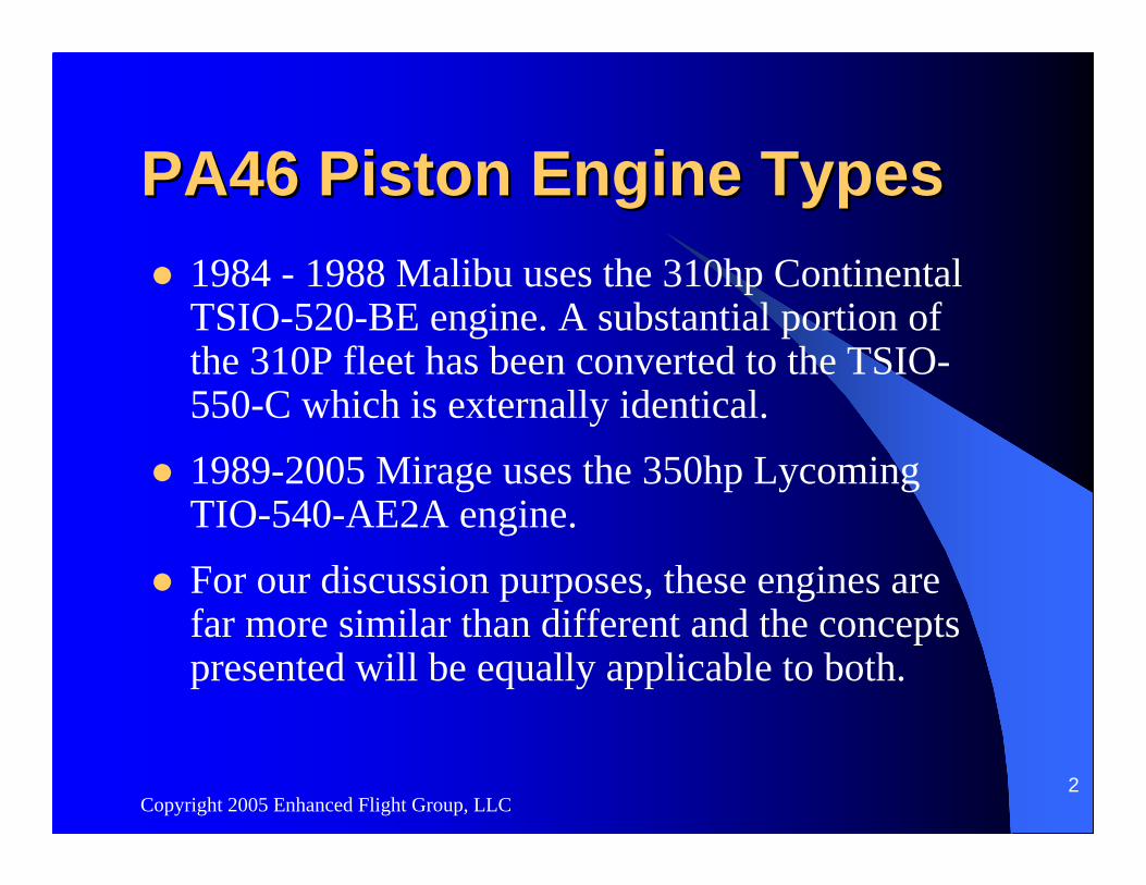
PA46 Piston Engine Types PA46 Piston Engine Types 1984 - 1988 Malibu uses the 310hp Continental TSIO-520-BE engine. A substantial portion of the 310P fleet has been converted to the TSIO-550-C which is externally identical.1989-2005 Mirage uses the 350hp Lycoming TIO-540-AE2A engine.For our discussion purposes, these engines are far more similar than different and the concepts presented will be equally applicable to both.
Copyright 2005 Enhanced Flight Group, LLC3
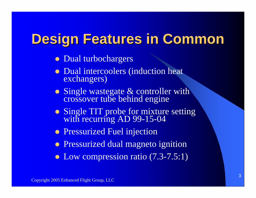
Design Features in CommonDesign Features in CommonDual turbochargersDual intercoolers (induction heat exchangers)Single wastegate & controller with crossover tube behind engineSingle TIT probe for mixture setting with recurring AD 99-15-04Pressurized Fuel injectionPressurized dual magneto ignitionLow compression ratio (7.3-7.5:1)
Copyright 2005 Enhanced Flight Group, LLC4
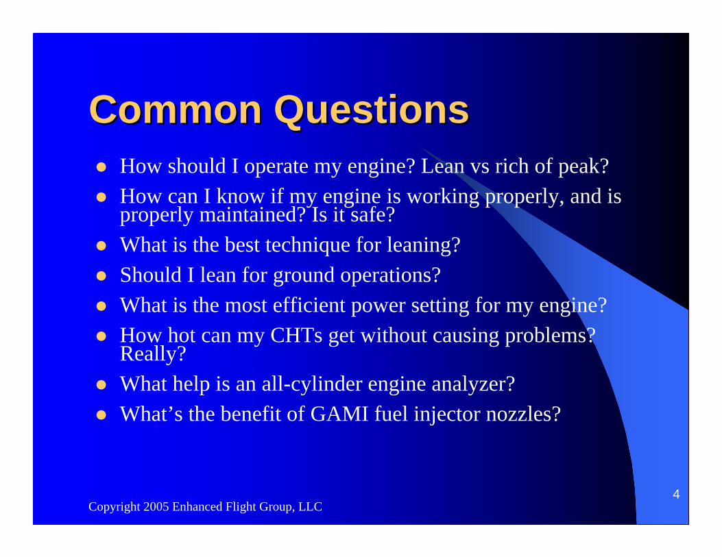
Common Questions Common Questions How should I operate my engine? Lean vs rich of peak?How can I know if my engine is working properly, and is properly maintained? Is it safe?What is the best technique for leaning?Should I lean for ground operations?What is the most efficient power setting for my engine?How hot can my CHTs get without causing problems? Really?What help is an all-cylinder engine analyzer?What’s the benefit of GAMI fuel injector nozzles?
Copyright 2005 Enhanced Flight Group, LLC5
ClosedClosed--loop, Turboloop, Turbo--Supercharged Supercharged Induction SystemInduction System
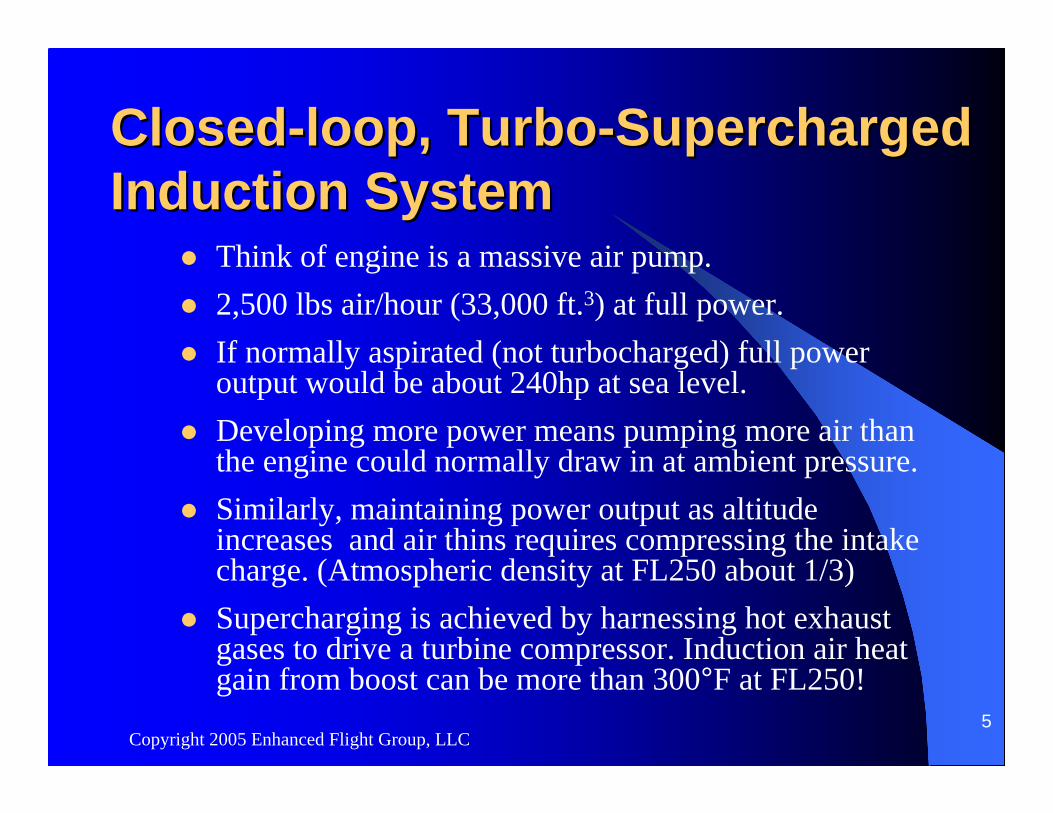
Think of engine is a massive air pump.2,500 lbs air/hour (33,000 ft.3) at full power.If normally aspirated (not turbocharged) full power output would be about 240hp at sea level.Developing more power means pumping more air than the engine could normally draw in at ambient pressure.Similarly, maintaining power output as altitude increases and air thins requires compressing the intake charge. (Atmospheric density at FL250 about 1/3)Supercharging is achieved by harnessing hot exhaust gases to drive a turbine compressor. Induction air heat gain from boost can be more than 300°F at FL250!
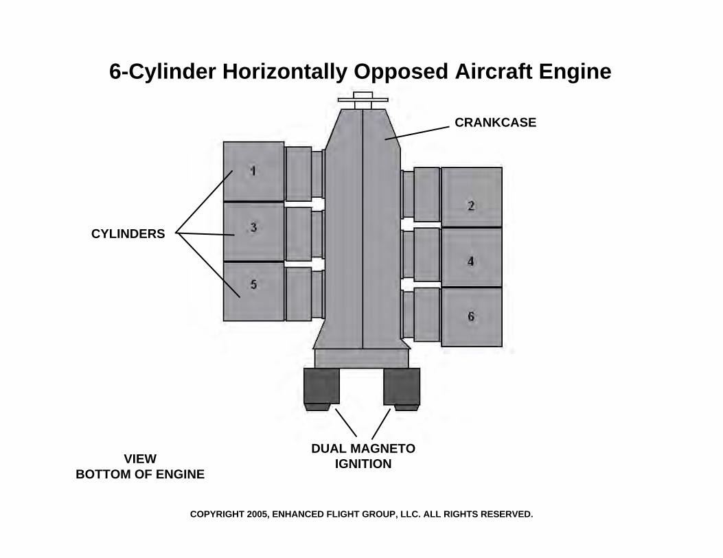
6-Cylinder Horizontally Opposed Aircraft Engine
CRANKCASE
CYLINDERS
DUAL MAGNETOIGNITIONVIEW
BOTTOM OF ENGINE
COPYRIGHT 2005, ENHANCED FLIGHT GROUP, LLC. ALL RIGHTS RESERVED.
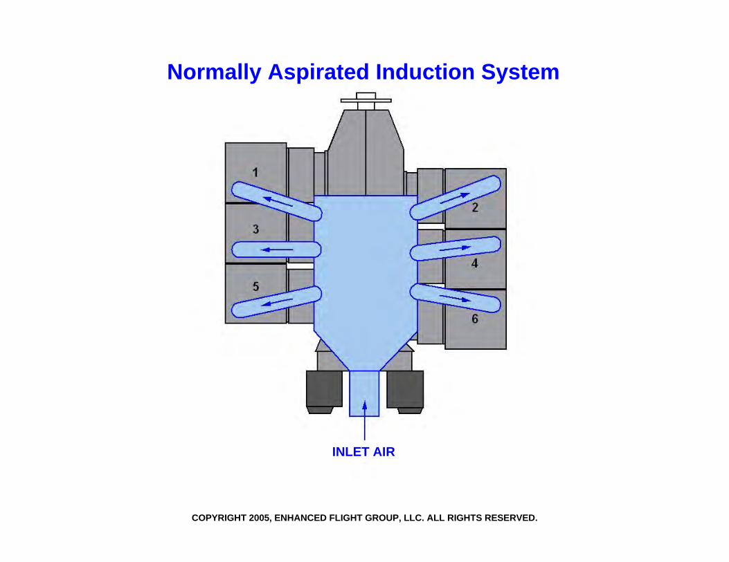
Normally Aspirated Induction System
INLET AIR
COPYRIGHT 2005, ENHANCED FLIGHT GROUP, LLC. ALL RIGHTS RESERVED.
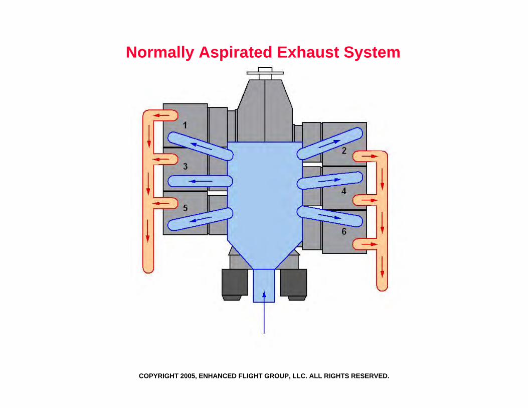
Normally Aspirated Exhaust System
COPYRIGHT 2005, ENHANCED FLIGHT GROUP, LLC. ALL RIGHTS RESERVED.
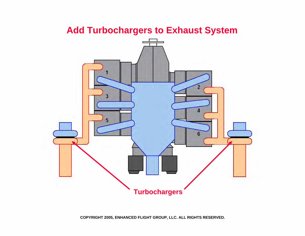
Add Turbochargers to Exhaust System
COPYRIGHT 2005, ENHANCED FLIGHT GROUP, LLC. ALL RIGHTS RESERVED.
Turbochargers
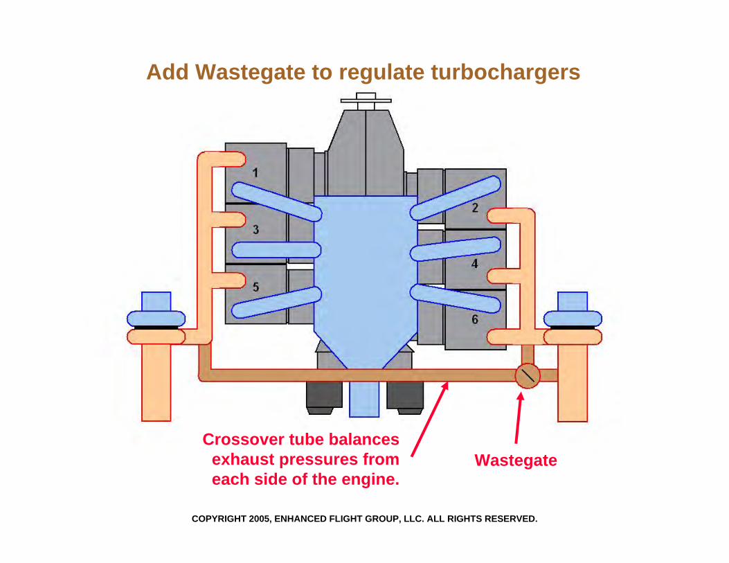
Add Wastegate to regulate turbochargers
COPYRIGHT 2005, ENHANCED FLIGHT GROUP, LLC. ALL RIGHTS RESERVED.
Crossover tube balancesexhaust pressures from each side of the engine.
Wastegate
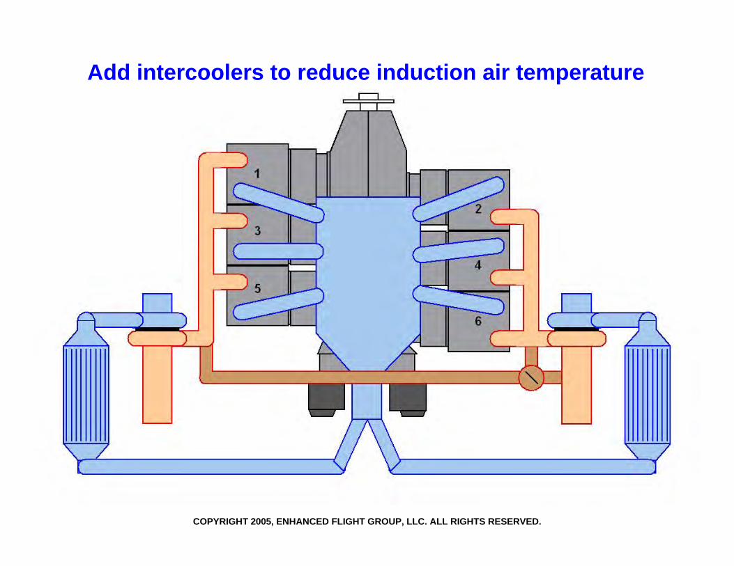
Add intercoolers to reduce induction air temperature
COPYRIGHT 2005, ENHANCED FLIGHT GROUP, LLC. ALL RIGHTS RESERVED.
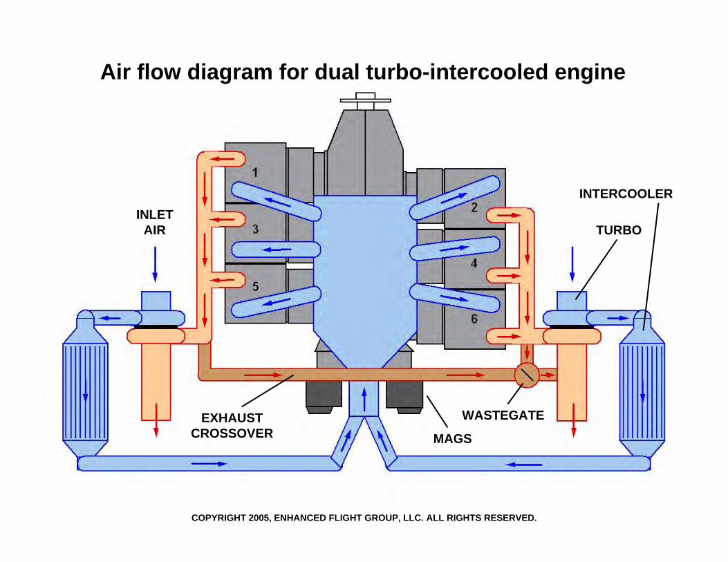
Air flow diagram for dual turbo-intercooled engine
WASTEGATE
MAGS
TURBO
INTERCOOLERINLET
AIR
EXHAUSTCROSSOVER
COPYRIGHT 2005, ENHANCED FLIGHT GROUP, LLC. ALL RIGHTS RESERVED.
Copyright 2005 Enhanced Flight Group, LLC13
InductionInduction--Exhaust SystemExhaust SystemIrrefutable Fact:Irrefutable Fact:A closed-loop system is, by definition, sealed and therefore compromised by any leakage. The proper operation of the turbocharged engine is completely dependent upon minimal leakage. It is also the nature of the system to wear and develop leaks as it vibrates, cycles thermally, corrodes, and is disassembled and reassembled for engine repairs. Assuring the integrity of this system must be a maintenance priority.
Copyright 2005 Enhanced Flight Group, LLC14
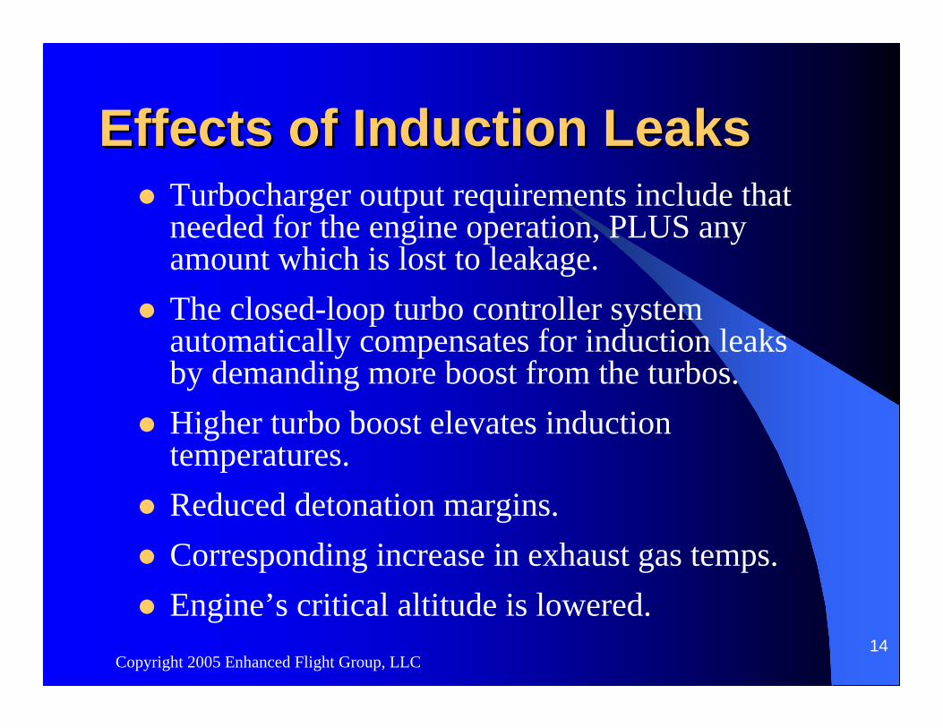
Effects of Induction LeaksEffects of Induction LeaksTurbocharger output requirements include that needed for the engine operation, PLUS any amount which is lost to leakage. The closed-loop turbo controller system automatically compensates for induction leaks by demanding more boost from the turbos.Higher turbo boost elevates induction temperatures.Reduced detonation margins.Corresponding increase in exhaust gas temps.Engine’s critical altitude is lowered.
Copyright 2005 Enhanced Flight Group, LLC15
Sources of Induction LeaksSources of Induction LeaksHigh pressure induction hosesIntake runner O-rings & gasketsMagnetos case sealsUpper deck pressure linesFuel injector nozzles

Copyright 2005 Enhanced Flight Group, LLC16
Effects of Exhaust LeaksEffects of Exhaust LeaksTurbocharger output requirements include that needed for the engine operation, PLUS any amount which is lost to leakage. The closed-loop turbo controller system automatically compensates for induction leaks by demanding more boost from the turbos.Higher turbo boost elevates induction temperatures.Reduced detonation margins.Corresponding increase in exhaust gas temps.Engine’s critical altitude is lowered.
Copyright 2005 Enhanced Flight Group, LLC17
Effects of Exhaust Leaks Effects of Exhaust Leaks (continued)
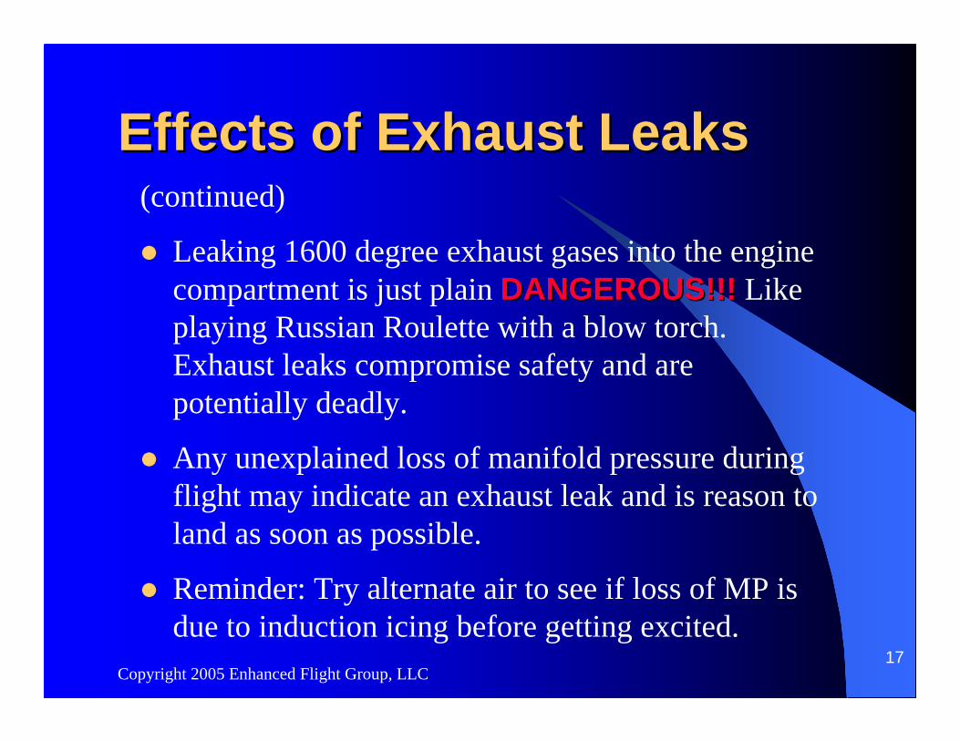
Leaking 1600 degree exhaust gases into the engine compartment is just plain DANGEROUS!!!DANGEROUS!!! Like playing Russian Roulette with a blow torch. Exhaust leaks compromise safety and are potentially deadly.
Any unexplained loss of manifold pressure during flight may indicate an exhaust leak and is reason to land as soon as possible.
Reminder: Try alternate air to see if loss of MP is due to induction icing before getting excited.
Copyright 2005 Enhanced Flight Group, LLC18
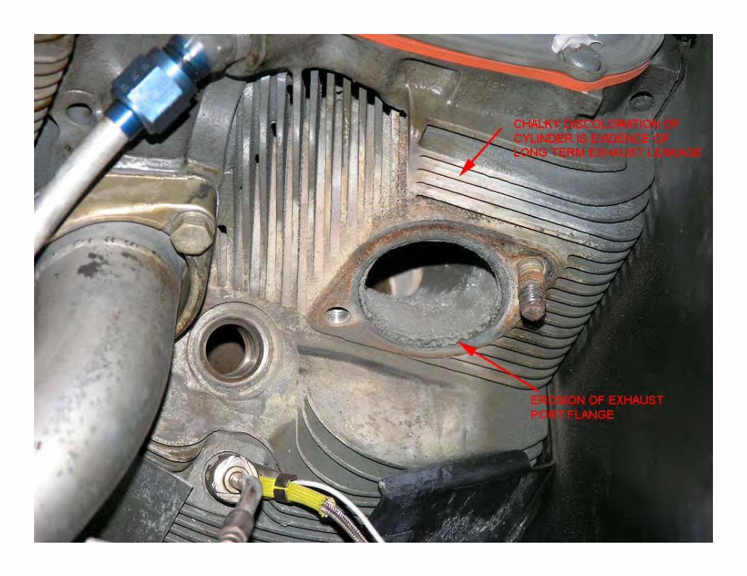
Sources of Exhaust LeaksSources of Exhaust LeaksExcessive wear at slip joints.Blown or worn cylinder exhaust port gaskets.

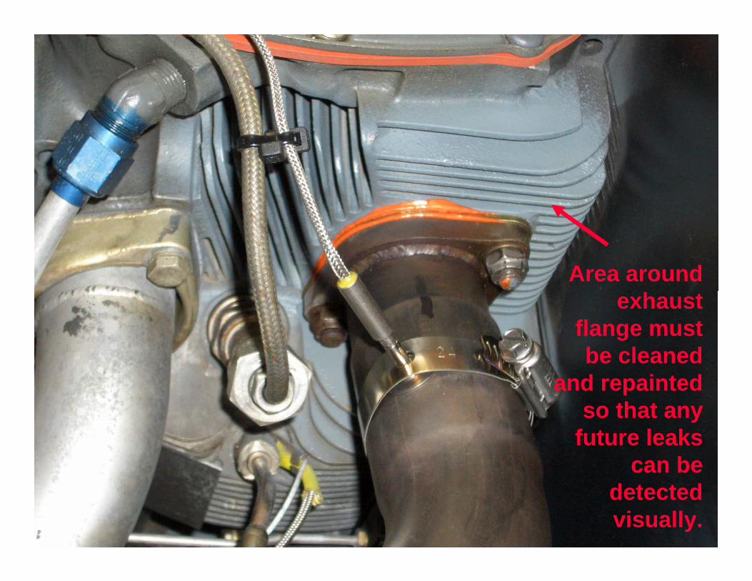
Area around exhaust
flange must be cleaned
and repainted so that any
future leaks can be
detected visually.
Copyright 2005 Enhanced Flight Group, LLC22
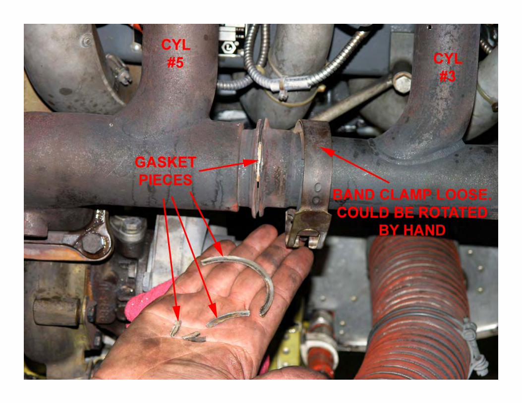
Sources of Exhaust LeaksSources of Exhaust LeaksExcessive wear at slip joints.Blown or worn cylinder exhaust port gaskets.Loose, broken, worn-out V-band clamps, gaskets, or flanges.
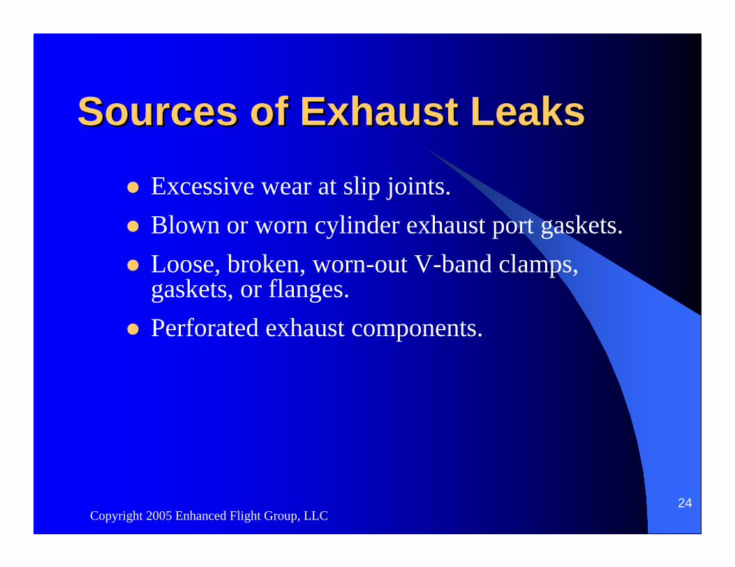
Copyright 2005 Enhanced Flight Group, LLC24
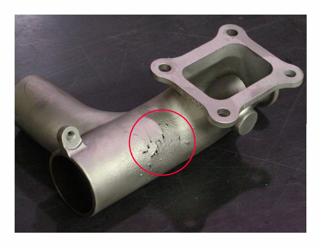
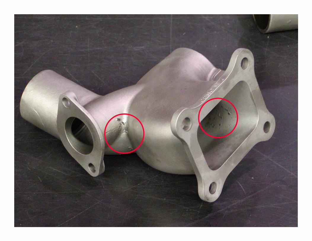
Sources of Exhaust LeaksSources of Exhaust LeaksExcessive wear at slip joints.Blown or worn cylinder exhaust port gaskets.Loose, broken, worn-out V-band clamps, gaskets, or flanges.Perforated exhaust components.
Copyright 2005 Enhanced Flight Group, LLC27
Methods for Detecting Methods for Detecting Induction & Exhaust LeaksInduction & Exhaust Leaks
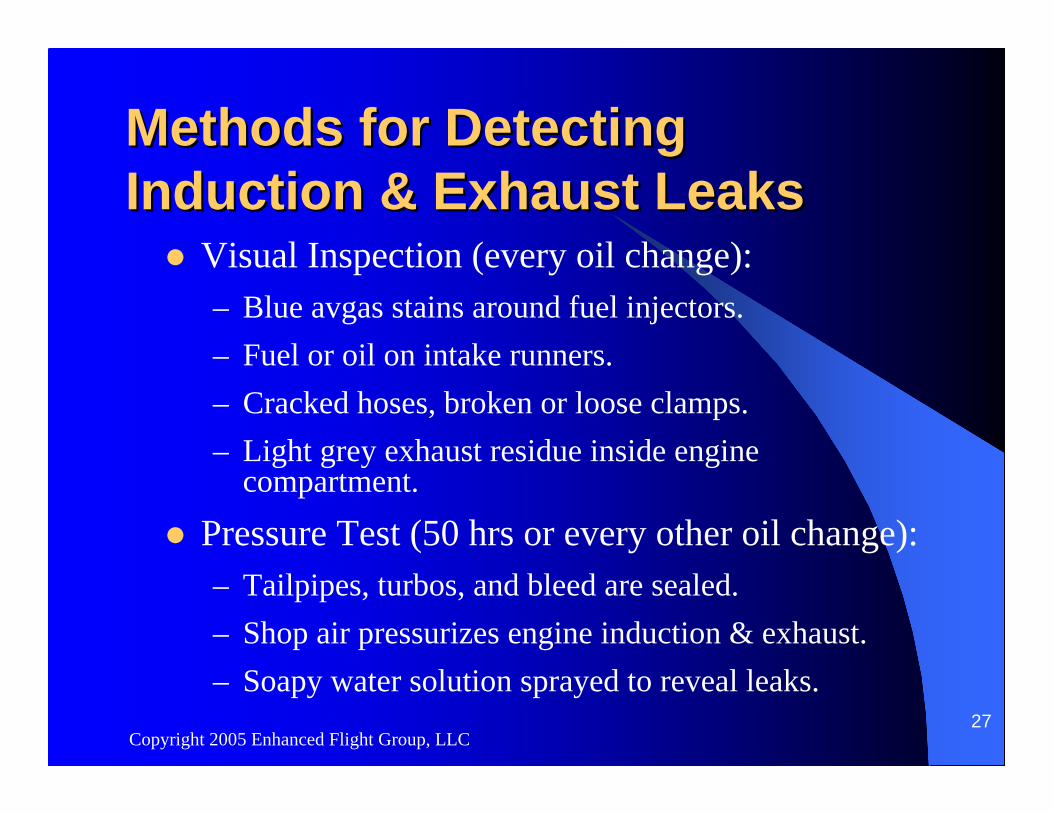
Visual Inspection (every oil change):– Blue avgas stains around fuel injectors.– Fuel or oil on intake runners.– Cracked hoses, broken or loose clamps.– Light grey exhaust residue inside engine
compartment.
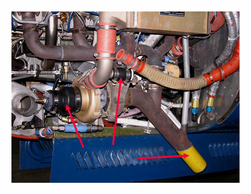
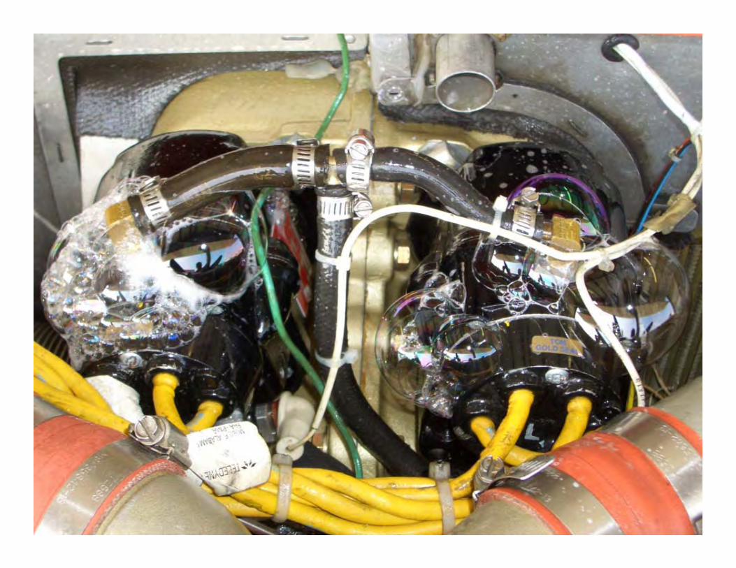
Pressure Test (50 hrs or every other oil change):– Tailpipes, turbos, and bleed are sealed.– Shop air pressurizes engine induction & exhaust.– Soapy water solution sprayed to reveal leaks.
Copyright 2005 Enhanced Flight Group, LLC28
EFG Induction/Exhaust Leak Test EFG Induction/Exhaust Leak Test Report No. 12003Report No. 12003--10041004
NOT something new or unique to EFG.FAA approved.Applicable to either Lycoming or TCM.Easy to perform.Copy of procedure, FREE!Leak test tool kit, $95
Copyright 2005 Enhanced Flight Group, LLC31
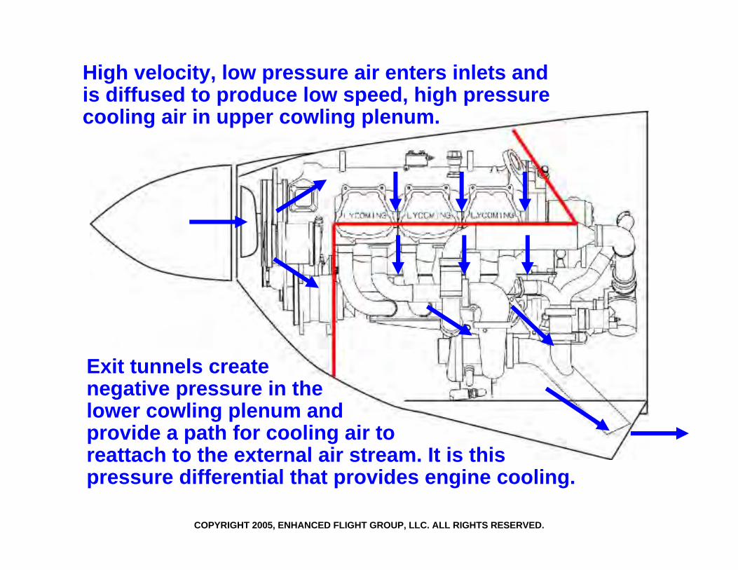
Engine Baffles, Seals, & CoolingEngine Baffles, Seals, & CoolingSheet metal baffles around the engine divide the cowling into two areas, or plenums.The upper/forward plenum uses ram inlet air to pressurize the top side of the cowling and force air down through cylinder cooling fins and heat exchangers into the lower plenum.Air exits the cowling through louvers in the nose gear doors and the exhaust tunnels, which create negative pressure in the lower plenum.Cooling the engine is accomplished by the pressure differential between the upper and lower plenums in the cowling.
Copyright 2005 Enhanced Flight Group, LLC32
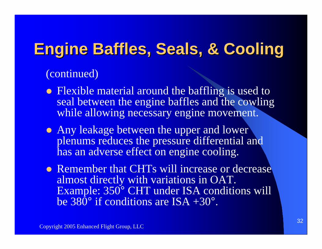
Engine Baffles, Seals, & CoolingEngine Baffles, Seals, & Cooling(continued)
Flexible material around the baffling is used to seal between the engine baffles and the cowling while allowing necessary engine movement.Any leakage between the upper and lower plenums reduces the pressure differential and has an adverse effect on engine cooling.Remember that CHTs will increase or decrease almost directly with variations in OAT. Example: 350° CHT under ISA conditions will be 380° if conditions are ISA +30°.
COPYRIGHT 2005, ENHANCED FLIGHT GROUP, LLC. ALL RIGHTS RESERVED.
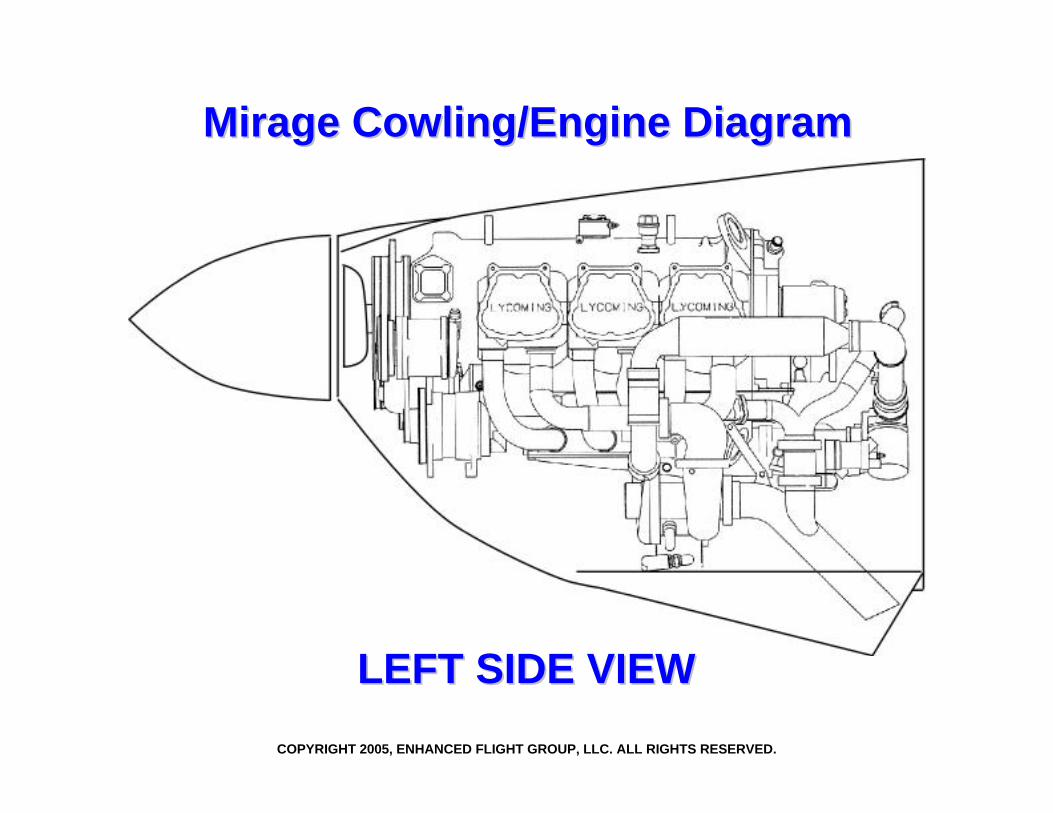
Mirage Cowling/Engine DiagramMirage Cowling/Engine Diagram
LEFT SIDE VIEWLEFT SIDE VIEW
COPYRIGHT 2005, ENHANCED FLIGHT GROUP, LLC. ALL RIGHTS RESERVED.
High velocity, low pressure air enters inlets and is diffused to produce low speed, high pressurecooling air in upper cowling plenum.
Exit tunnels createnegative pressure in the lower cowling plenum andprovide a path for cooling air toreattach to the external air stream. It is thispressure differential that provides engine cooling.
Copyright 2005 Enhanced Flight Group, LLC35
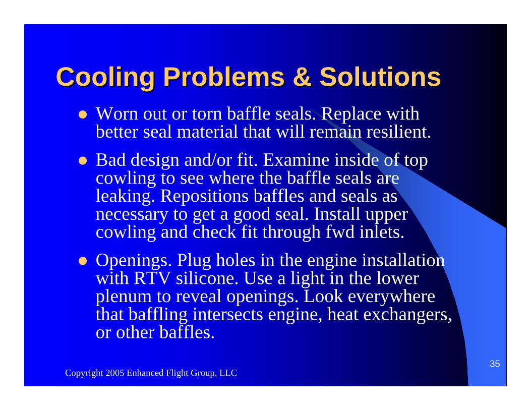
Cooling Problems & SolutionsCooling Problems & SolutionsWorn out or torn baffle seals. Replace with better seal material that will remain resilient.Bad design and/or fit. Examine inside of top cowling to see where the baffle seals are leaking. Repositions baffles and seals as necessary to get a good seal. Install upper cowling and check fit through fwd inlets.Openings. Plug holes in the engine installation with RTV silicone. Use a light in the lower plenum to reveal openings. Look everywhere that baffling intersects engine, heat exchangers, or other baffles.
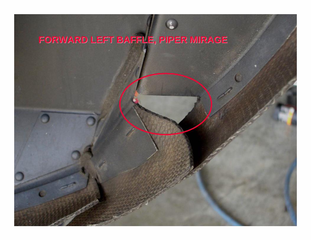
FORWARD LEFT BAFFLE, PIPER MIRAGEFORWARD LEFT BAFFLE, PIPER MIRAGE
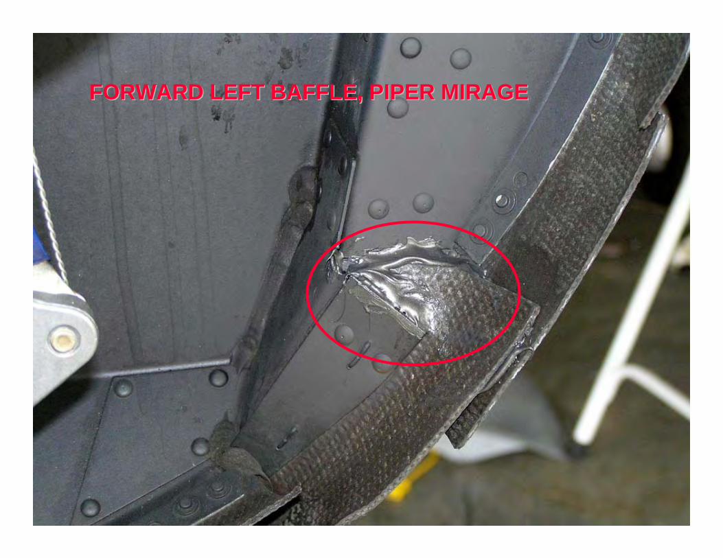
FORWARD LEFT BAFFLE, PIPER MIRAGEFORWARD LEFT BAFFLE, PIPER MIRAGE
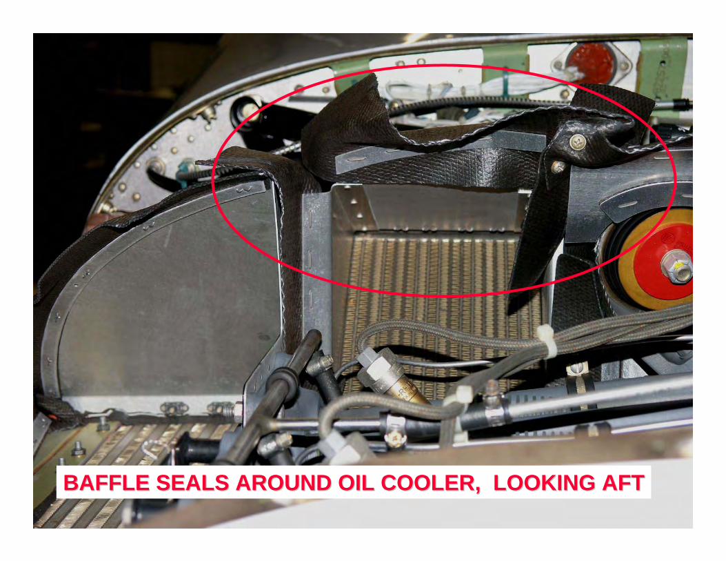
BAFFLE SEALS AROUND OIL COOLER, LOOKING AFTBAFFLE SEALS AROUND OIL COOLER, LOOKING AFT
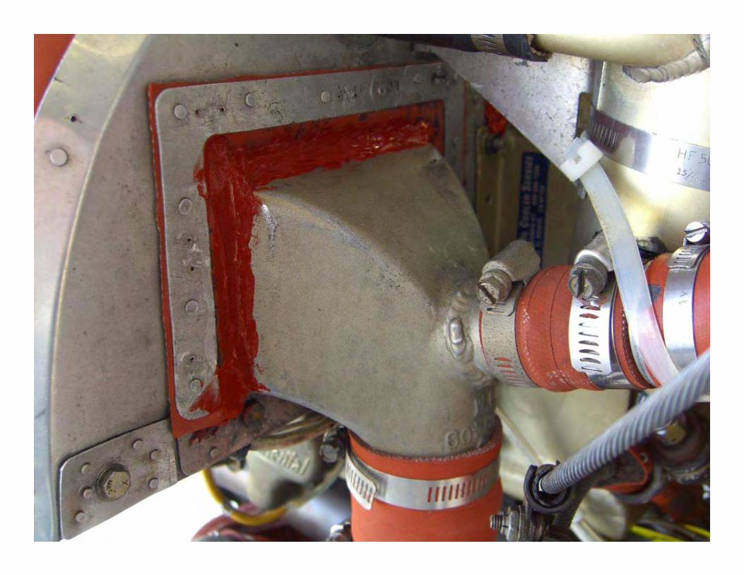

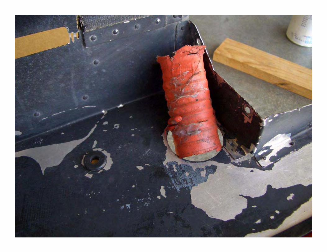
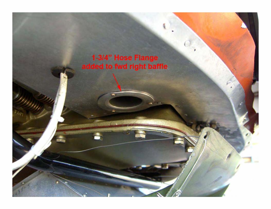
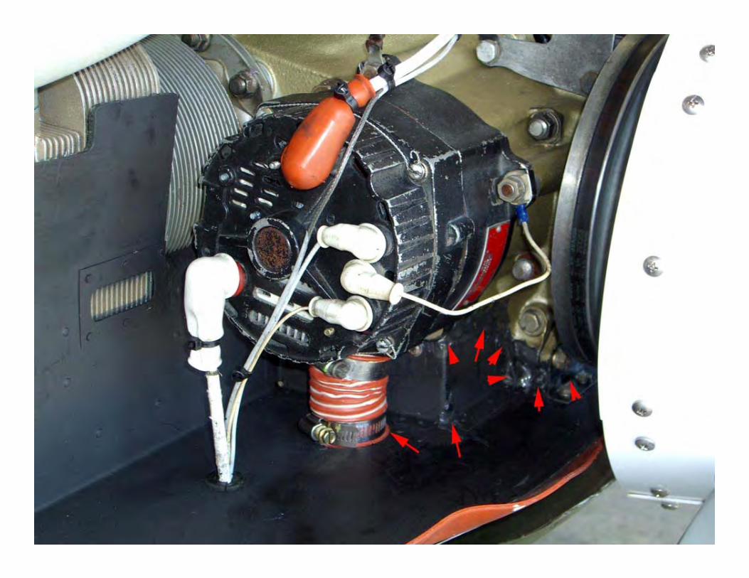
Fwd right baffle, alternator vent to bottom plenumFwd right baffle, alternator vent to bottom plenum
Copyright 2005 Enhanced Flight Group, LLC44
Cooling Problems & SolutionsCooling Problems & Solutions(continued)
Debris. Bird nest material. If not found prior to flight, gets blown down through cylinder cooling fins and very difficult to get out. Use cowl plugs if necessary to prevent this.Heat exchanger fins damaged, bent over impeding air flow. Usually caused from side baffle being used as a “tool shelf” during maintenance, or loose hardware (valve cover screws) rattling around during flight.
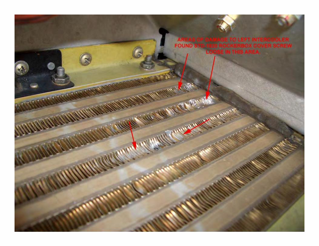

Copyright 2005 Enhanced Flight Group, LLC46
The Challenge of High Altitude The Challenge of High Altitude Piston Engine OperationPiston Engine Operation
At FL180 std conditions, the air density is 14.94”HG or ½ of sea level pressure. (-5.2°F)At service ceiling, it is only 11.10”HG or 1/3 the density at sea level. (-30.2°F)Despite cooler air at higher altitudes, the reduced air density is the greater factor for carrying away heat from the engine. Also, since indicated airspeed decreases with altitude, this further complicates getting sufficient mass air flow into the cowling for adequate cooling.
Copyright 2005 Enhanced Flight Group, LLC47
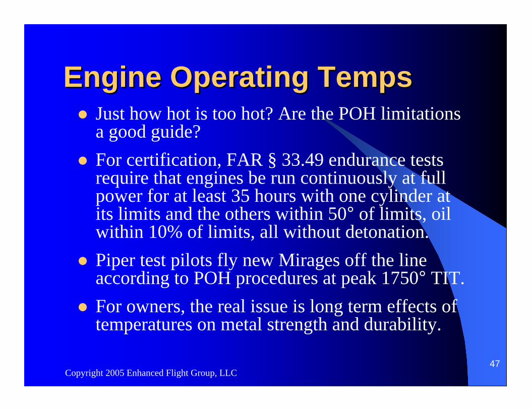
Engine Operating TempsEngine Operating TempsJust how hot is too hot? Are the POH limitations a good guide?For certification, FAR § 33.49 endurance tests require that engines be run continuously at full power for at least 35 hours with one cylinder at its limits and the others within 50° of limits, oil within 10% of limits, all without detonation.Piper test pilots fly new Mirages off the line according to POH procedures at peak 1750° TIT.For owners, the real issue is long term effects of temperatures on metal strength and durability.
Copyright 2005 Enhanced Flight Group, LLC48
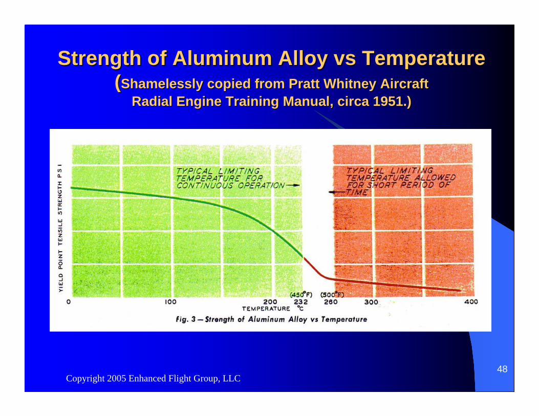
Strength of Aluminum Alloy Strength of Aluminum Alloy vsvs TemperatureTemperature((Shamelessly copied from Pratt Whitney Aircraft Shamelessly copied from Pratt Whitney Aircraft
Radial Engine Training Manual, circa 1951.)Radial Engine Training Manual, circa 1951.)
Strength of Aluminum Alloy Strength of Aluminum Alloy vsvs TemperatureTemperature((Shamelessly copied from Pratt Whitney Aircraft, 1951.)Shamelessly copied from Pratt Whitney Aircraft, 1951.)
Copyright 2005 Enhanced Flight Group, LLC50
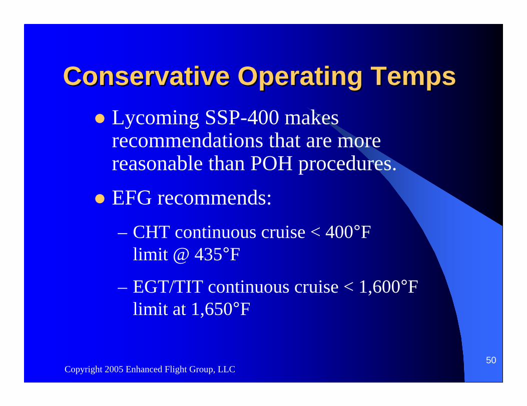
Conservative Operating TempsConservative Operating TempsLycoming SSP-400 makes recommendations that are more reasonable than POH procedures.EFG recommends:– CHT continuous cruise < 400°F
limit @ 435°F
– EGT/TIT continuous cruise < 1,600°F limit at 1,650°F
Copyright 2005 Enhanced Flight Group, LLC51
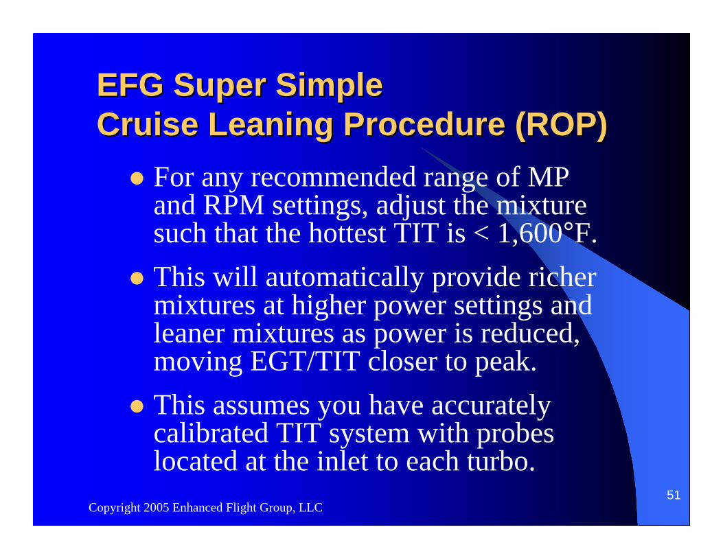
EFG Super Simple EFG Super Simple Cruise Leaning Procedure (ROP)Cruise Leaning Procedure (ROP)
For any recommended range of MP and RPM settings, adjust the mixture such that the hottest TIT is < 1,600°F.This will automatically provide richer mixtures at higher power settings and leaner mixtures as power is reduced, moving EGT/TIT closer to peak.This assumes you have accurately calibrated TIT system with probes located at the inlet to each turbo.
Copyright 2005 Enhanced Flight Group, LLC53
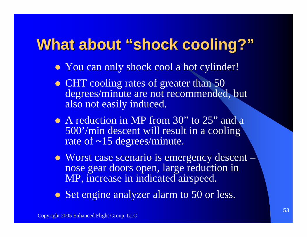
What about What about ““shock cooling?shock cooling?””You can only shock cool a hot cylinder!CHT cooling rates of greater than 50 degrees/minute are not recommended, but also not easily induced.A reduction in MP from 30” to 25” and a 500’/min descent will result in a cooling rate of ~15 degrees/minute.Worst case scenario is emergency descent –nose gear doors open, large reduction in MP, increase in indicated airspeed.Set engine analyzer alarm to 50 or less.
Copyright 2005 Enhanced Flight Group, LLC54
What about ground leaning?What about ground leaning?Full rich mixture is required at start, but afterwards is overly rich and will cause fowling of spark plugs during extended idle or taxi operations.Leaning mixture for max RPM will help prevent spark plug fowling.Leaning mixture for max RPM at run up will help clear fowled plugs and better reveal ignition problems.
Copyright 2005 Enhanced Flight Group, LLC58
What about ground leaning?What about ground leaning?
One problem: risk of lean takeoff.Requires different throttle advance technique at takeoff to assure that mixture control is brought full forward for takeoff.
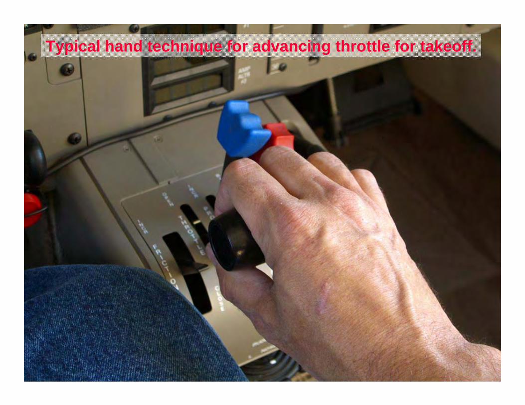
Typical hand technique for advancing throttle for takeoff.Typical hand technique for advancing throttle for takeoff.
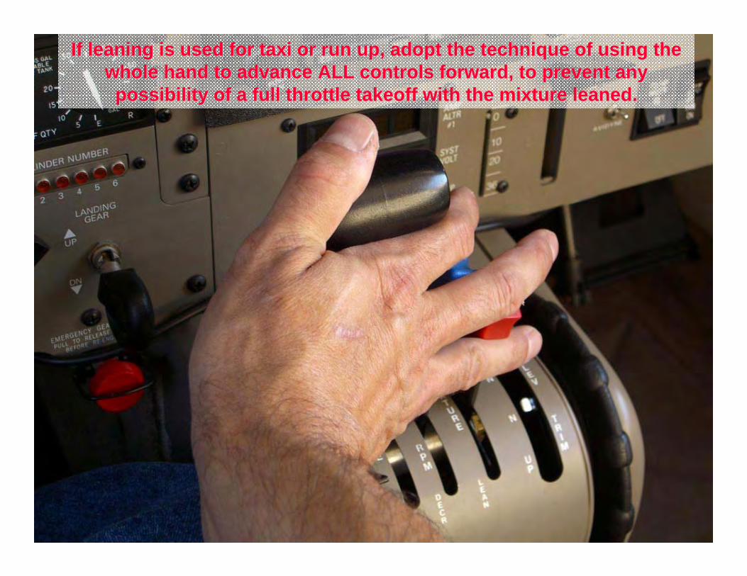
If leaning is used for taxi or run up, adopt the technique of usIf leaning is used for taxi or run up, adopt the technique of using the ing the whole hand to advance ALL controls forward, to prevent any whole hand to advance ALL controls forward, to prevent any possibility of a full throttle takeoff with the mixture leaned.possibility of a full throttle takeoff with the mixture leaned.
Copyright 2005 Enhanced Flight Group, LLC61
What about lean of peak?What about lean of peak?Wide tolerances in OEM fuel nozzles produce variations in cylinder-to-cylinder fuel/air mixture ratios.Running ROP, these variations in mixture do NOT cause significant differences in power from one cylinder to another.Running LOP, unbalanced fuel/air mixtures will cause leaner cylinders to produce less power than richer ones, which is felt as vibration or roughness.
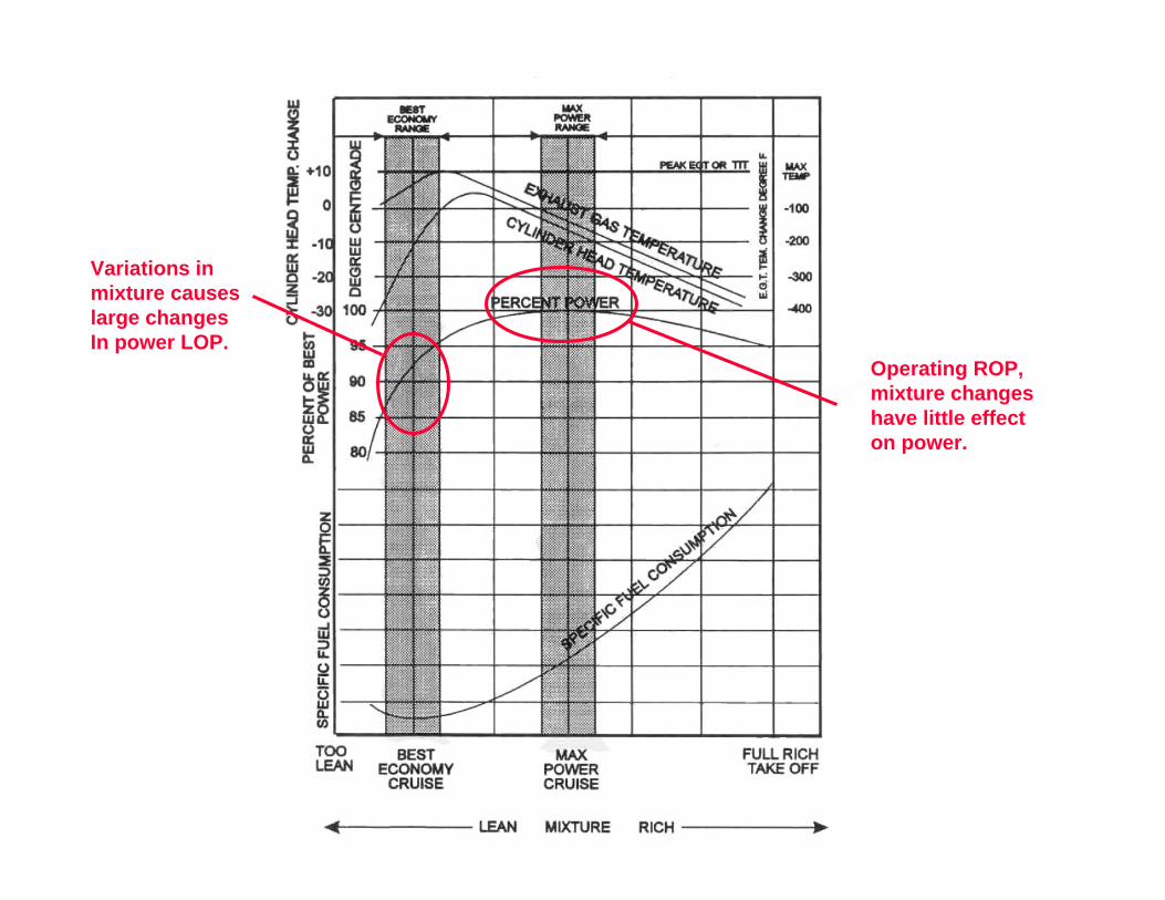
Variations inmixture causeslarge changesIn power LOP.
Operating ROP, mixture changeshave little effecton power.
Copyright 2005 Enhanced Flight Group, LLC63
What about lean of peak?What about lean of peak?Benefits of LOP operation are lower CHTs and greater fuel efficiency.Smooth LOP operation can only be achieved with balanced fuel/air ratios, which may not be possible with a random mix of OEM nozzles.All-cylinder EGT is recommended.EGT/TITs may be higher than ROP.
Copyright 2005 Enhanced Flight Group, LLC64
What power setting will What power setting will produce the maximum range?produce the maximum range?
Rm = Ee + Pe
Maximum range will be achieved at maximum engine efficiency plus maximum propeller efficiency.Engine efficiency is specified as the pounds of fuel required to generate 1hp/hour, or brake specific fuel consumption or BSFC.Reference engine leaning chart:
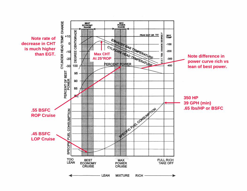
350 HP39 GPH (min).65 lbs/HP or BSFC.55 BSFC
ROP Cruise
.45 BSFCLOP Cruise
Note difference inpower curve rich vslean of best power.
Max CHTAt 25°ROP
Note rate of decrease in CHT
is much higher than EGT.
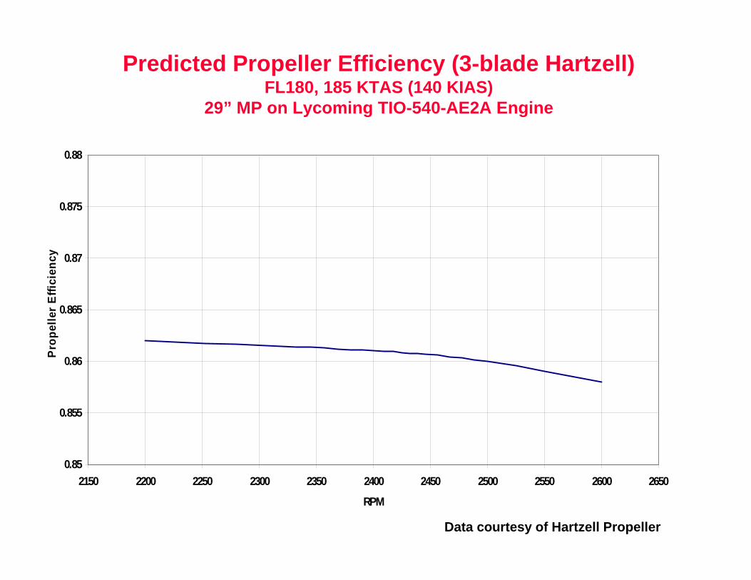
Predicted Propeller Efficiency (3-blade Hartzell)FL180, 185 KTAS (140 KIAS)
29” MP on Lycoming TIO-540-AE2A Engine
Data courtesy of Hartzell Propeller
0.85
0.855
0.86
0.865
0.87
0.875
0.88
2150 2200 2250 2300 2350 2400 2450 2500 2550 2600 2650
RPM
Pro
pelle
r Effi
cien
cy
Copyright 2005 Enhanced Flight Group, LLC67
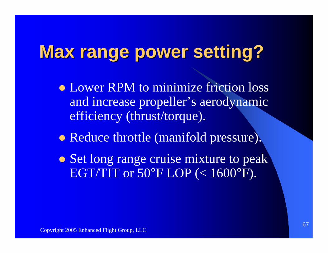
Max range power setting?Max range power setting?
Lower RPM to minimize friction loss and increase propeller’s aerodynamic efficiency (thrust/torque).Reduce throttle (manifold pressure).Set long range cruise mixture to peak EGT/TIT or 50°F LOP (< 1600°F).
Copyright 2005 Enhanced Flight Group, LLC68
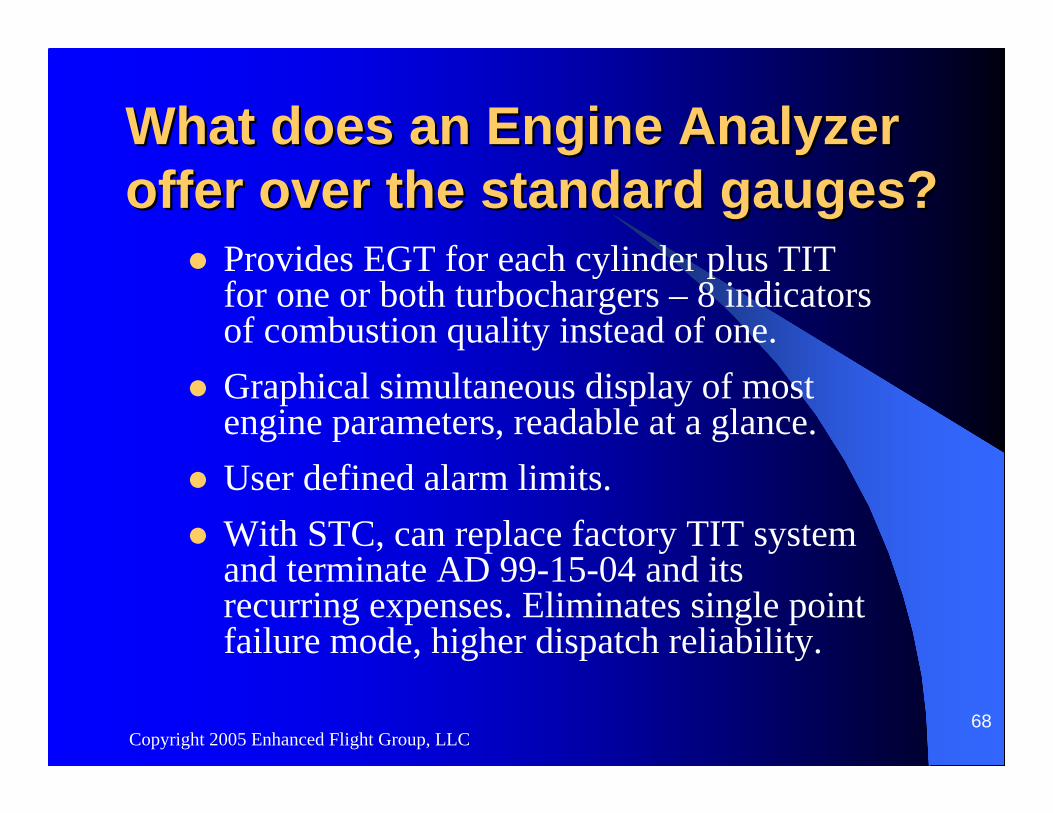
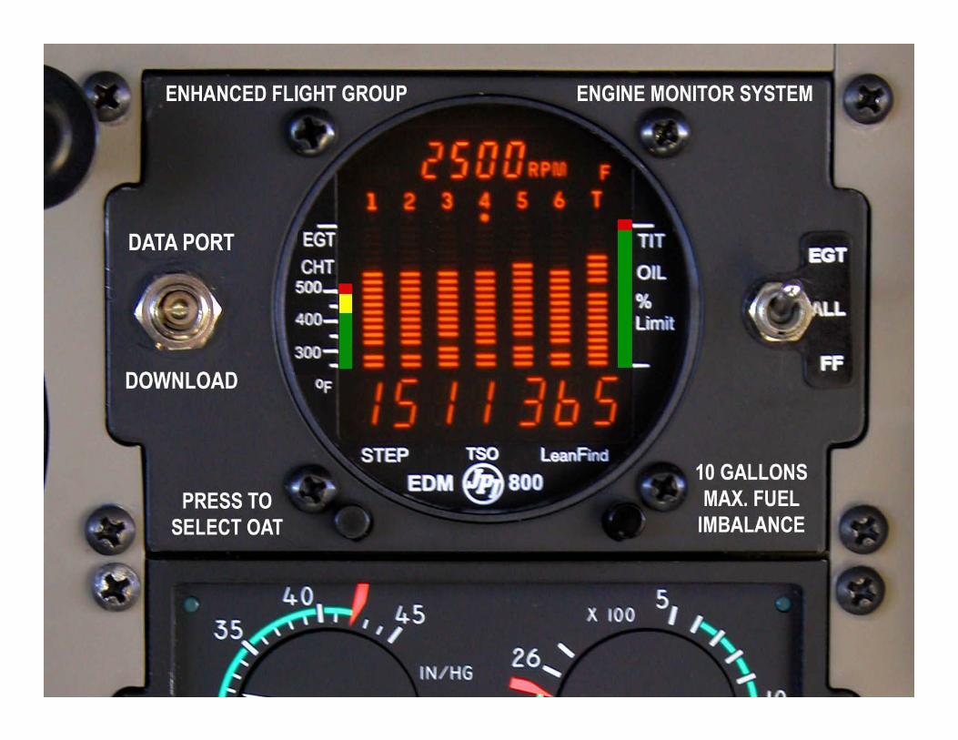
What does an Engine Analyzer What does an Engine Analyzer offer over the standard gauges?offer over the standard gauges?
Provides EGT for each cylinder plus TIT for one or both turbochargers – 8 indicators of combustion quality instead of one.Graphical simultaneous display of most engine parameters, readable at a glance.User defined alarm limits.With STC, can replace factory TIT system and terminate AD 99-15-04 and its recurring expenses. Eliminates single point failure mode, higher dispatch reliability.
Copyright 2005 Enhanced Flight Group, LLC69
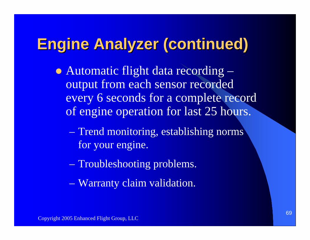
Engine Analyzer (continued)Engine Analyzer (continued)Automatic flight data recording –output from each sensor recorded every 6 seconds for a complete record of engine operation for last 25 hours. – Trend monitoring, establishing norms
for your engine.
– Troubleshooting problems.
– Warranty claim validation.

Copyright 2005 Enhanced Flight Group, LLC72
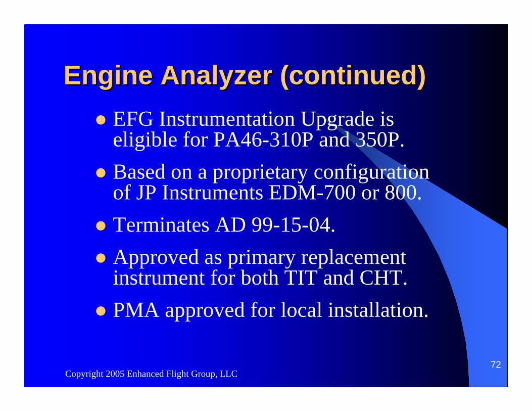
Engine Analyzer (continued)Engine Analyzer (continued)EFG Instrumentation Upgrade is eligible for PA46-310P and 350P.Based on a proprietary configuration of JP Instruments EDM-700 or 800.Terminates AD 99-15-04.Approved as primary replacement instrument for both TIT and CHT.PMA approved for local installation.