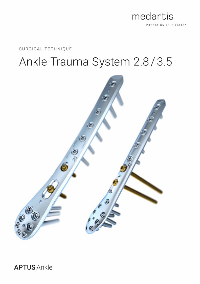
SURGICAL TECHNIQUE Ankle Trauma System 2.8 / 3
68
APTUS Ankle Ankle Trauma System 2.8 / 3.5 SURGICAL TECHNIQUE
Transcript of SURGICAL TECHNIQUE Ankle Trauma System 2.8 / 3
APTUS Ankle
Ankle Trauma System 2.8 / 3.5S U R G I C A L T E C H N I Q U E

Contents
2 l Ankle Trauma System 2.8 / 3.5
medartis.com
3 Introduction 3 Product Materials 3 Indications 3 Contraindications 3 Color Coding 3 Possible Combination of Plates and Screws 3 Symbols 4 System Overview 4 Distal Tibia Plates 5 Distal Fibula Plates 7 Treatment Concept 7 Distal Tibia 9 Distal Fibula10 Instrument Application10 General Instrument Application10 Sizing Templates11 Bending 13 Bending of Flaps13 Plate Holding and Positioning15 Drilling18 Assigning the Screw Length18 Screw Pick-Up20 Specific Instrument Application20 MIPO Instrument for Tunnel Preparation20 2.8/3.5 Plate Holding and Positioning Instrument21 Large Reduction Forceps21 Drill Guide for Compression22 Surgical Techniques22 General Surgical Techniques22 Lag Screw Technique24 Specific Surgical Techniques24 2.8/3.5 TriLock Distal Tibia Plates Medial24 Distal Tibial Fracture26 Supramalleolar Tibial Osteotomy29 2.8/3.5 TriLock Distal Tibia Plates, Anterolateral32 2.8/3.5 TriLock Distal Fibula Plates, Lateral32 Distal Fibula Fracture33 2.8/3.5 TriLock Distal Fibula Plates, Lateral, with Flap35 Distal Fibula Osteotomy37 2.8 TriLock Distal Fibula Plates37 2.8 TriLock Distal Fibula Plates, Straight39 3.5 Distal Tibia T and L Plates41 Explantation41 Removal of Screws42 TriLock Locking Technology42 Correct Application of the TriLock Locking Technology – 2.8 TriLock Screws43 Correct Application of the TriLock Locking Technology – 3.5 TriLock Screws 44 Correct Locking (±15°) of the TriLock Screws in the Plate45 Implants, Instruments and Containers
For further information regarding the APTUS product line visit www.medartis.com
See Instructions for Usewww.medartis.com
Ankle Trauma System 2.8 / 3.5 l 3
medartis.com
IntroductionPossible Combination of Plates and Screws
Plates and screws can be combined within one system size:
2.8/3.5 TriLock Distal Tibia Plates2.8 Cortical Screws, HexaDrive 72.8 TriLock Screws, HexaDrive 73.5 Cortical Screws, HexaDrive 153.5 TriLock Screws, HexaDrive 15
3.5 TriLock Distal Tibia T + L Plates3.5 Cortical Screws, HexaDrive 153.5 TriLock Screws, HexaDrive 15
2.8/3.5 TriLock Distal Fibula Plates2.8 Cortical Screws, HexaDrive 72.8 TriLock Screws, HexaDrive 73.5 Cortical Screws, HexaDrive 153.5 TriLock Screws, HexaDrive 15
2.8 TriLock Distal Fibula Plates2.8 Cortical Screws, HexaDrive 72.8 TriLock Screws, HexaDrive 7
Symbols
HexaDrive
TriLock screw hole on sizing templates
Product Materials
APTUS implants, plates and screws, are made of pure titanium (ASTM F67, ISO 5832-2) or titanium alloy (ASTM F136, ISO 5832-3). All of the titanium materials used are biocompatible, corrosion-resistant and non-toxic in a biological environment.K-wires and staples are made of stainless steel (ASTM F138, ASTM F139); instruments are made of stainless steel, PEEK, aluminum, Nitinol or titanium.
Indications
APTUS Ankle Fixation of fractures, osteotomies, malunions and non-unions of the distal tibia and fibula
Contraindications
- Pre-existing or suspected infection at or near the implantation site
- Known allergies and/or hypersensitivity to implant materials
- Inferior or insufficient bone quality to securely anchor the implant
- Patients who are incapacitated and/or uncooperative during the treatment phase
- Growth plates are not to be blocked with plates and screws
Color Coding
System Size Color Code2.8 Orange3.5 Green
Plates and ScrewsSpecial implant plates and screws have their own color:Implant plates blue TriLock plates (locking)Implant screws gold Cortical screws (fixation)Implant screws blue TriLock screws (locking)
4 l Ankle Trauma System 2.8 / 3.5
medartis.com
System OverviewThe plates of the APTUS Ankle Trauma System 2.8/3.5 are available in the following designs:
Distal Tibia Plates
2.8/3.5 TriLock Distal Tibia Plates Medial are available in eight lengths in left and right versions. Plates are available sterile and non-sterile, while the long plates from 19 to 25 holes are only available sterile.
A-4954.1717-hole, left
A-4954.1313-hole, left
A-4954.1211-hole, right
A-4954.1615-hole, right
A-4954.1515-hole, left
A-4954.1111-hole, left
A-4954.1413-hole, right
A-4954.1817-hole, right
A-4954.25S25-hole, leftsterile only
A-4954.21S21-hole, leftsterile only
A-4954.23S23-hole, leftsterile only
A-4954.19S19-hole, leftsterile only
A-4954.20S19-hole, rightsterile only
A-4954.24S23-hole, rightsterile only
A-4954.22S21-hole, rightsterile only
A-4954.26S25-hole, rightsterile only
Ankle Trauma System 2.8 / 3.5 l 5
medartis.com
2.8/3.5 TriLock Distal Tibia Plates Anterolateral are available in five lengths in left and right versions. Plates are available sterile and non-sterile, while the long plates with 19 and 21 holes are only available sterile.
A-4954.3517-hole, left
A-4954.3113-hole, left
A-4954.3415-hole, right
A-4954.3315-hole, left
A-4954.3213-hole, right
A-4954.3617-hole, right
A-4954.39S21-hole, leftsterile only
A-4954.38S19-hole, rightsterile only
A-4954.37S19-hole, leftsterile only
A-4954.40S21-hole, rightsterile only
3.5 TriLock Distal Tibia T and L Plates are available in one length. The L plates are available in a left and right version. All plates are available sterile and non-sterile.
A-4954.1013/3 hole, T
A-4954.1033/3 hole, L, left
A-4954.1023/3 hole, L, right
2.8/3.5 TriLock Distal Fibula Plates Lateral are available in five lengths in left and right versions. All plates are available sterile and non-sterile, while the long lengths with 19 and 21 holes are only available sterile.
Distal Fibula Plates
A-4954.09S21-hole, leftsterile only
A-4954.0517-hole, left
A-4954.01 13-hole, left
A-4954.0215-hole, right
A-4954.06S19-hole, right sterile only
A-4954.07S19-hole, leftsterile only
A-4954.0013-hole, right
A-4954.0417-hole, right
A-4954.08S21-hole, right sterile only
A-4954.0315-hole, left
6 l Ankle Trauma System 2.8 / 3.5
medartis.com
2.8/3.5 TriLock Distal Fibula Plates Lateral with Flap are available in two lengths in left and right versions. All plates are available sterile and non-sterile.
A-4954.5114-hole, left
A-4954.5214-hole, right
A-4954.5316-hole, left
A-4954.5416-hole, right
A-4854.057-hole
A-4854.069-hole
A-4854.0711-hole
A-4854.0813-hole
A-4854.0915-hole
2.8 TriLock Distal Fibula Plates, Straight, are available in five lengths. All plates are available sterile and non-sterile.
2.8 TriLock Distal Fibula Plates are available in five lengths. All plates are available sterile and non-sterile.
A-4854.003/6-hole
A-4854.013/8-hole
A-4854.023/10-hole
A-4854.033/12-hole
A-4854.043/14-hole

Ankle Trauma System 2.8 / 3.5 l 7
medartis.com
Distal Tibia
Treatment ConceptThe table below lists typical clinical conditions which can be treated with the implants of the APTUS Ankle Trauma System 2.8/3.5.
AO/OTA Classification Description Screw Projection Options Treatment Options
Extra-articular (43-A)
43-A1
SimpleExtra-articularMetaphyseal
43-A2
Extra-articularMetaphysealWedge fracture
43-A3
Extra-articularMetaphysealMultifragmentary fracture
The above-mentioned information is a recommendation only. The operating surgeon is solely responsible for the choice of the suitable implant for the specific case.
8 l Ankle Trauma System 2.8 / 3.5
medartis.com
The above-mentioned information is a recommendation only. The operating surgeon is solely responsible for the choice of the suitable implant for the specific case.
AO/OTA Classification Description Screw Projection Options Treatment Options
Complete articular (43-C)
43-C1
Complete articular Simple articularSimple metaphyseal
43-C2
Complete articular Simple articularMultifragmentary metaphyseal
43 -C3
Complete articular Multifragmentary articularMultifragmentary metaphyseal
AO/OTA Classification Description Screw Projection Options Treatment Options
Partial articular (43-B)
43-B1
Partial articularSplit fracturesAnterior or posterior Volkmann
43-B2
Partial articularSplit with depressionAnterior or posterior Volkmann
43-B3
Partial articularMultifragmentary depression Anterior or posterior Volkmann
Ankle Trauma System 2.8 / 3.5 l 9
medartis.com
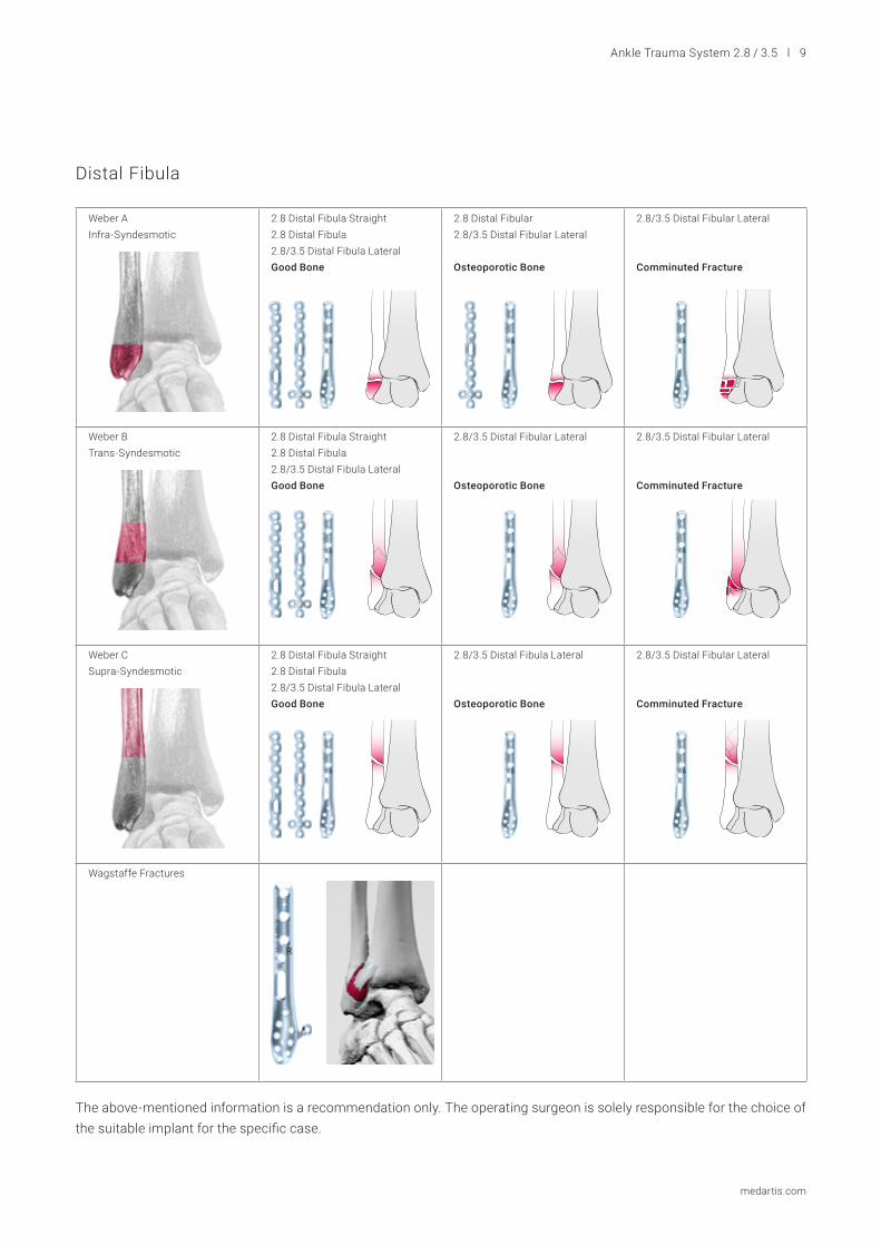
Distal Fibula
The above-mentioned information is a recommendation only. The operating surgeon is solely responsible for the choice of the suitable implant for the specific case.
Weber AInfra-Syndesmotic
2.8 Distal Fibula Straight2.8 Distal Fibula 2.8/3.5 Distal Fibula LateralGood Bone
2.8 Distal Fibular 2.8/3.5 Distal Fibular Lateral
Osteoporotic Bone
2.8/3.5 Distal Fibular Lateral
Comminuted Fracture
Weber BTrans-Syndesmotic
2.8 Distal Fibula Straight2.8 Distal Fibula 2.8/3.5 Distal Fibula LateralGood Bone
2.8/3.5 Distal Fibular Lateral
Osteoporotic Bone
2.8/3.5 Distal Fibular Lateral
Comminuted Fracture
Weber C Supra-Syndesmotic
2.8 Distal Fibula Straight2.8 Distal Fibula 2.8/3.5 Distal Fibula LateralGood Bone
2.8/3.5 Distal Fibula Lateral
Osteoporotic Bone
2.8/3.5 Distal Fibular Lateral
Comminuted Fracture
Wagstaffe Fractures
10 l Ankle Trauma System 2.8 / 3.5
medartis.com
Instrument ApplicationGeneral Instrument Application
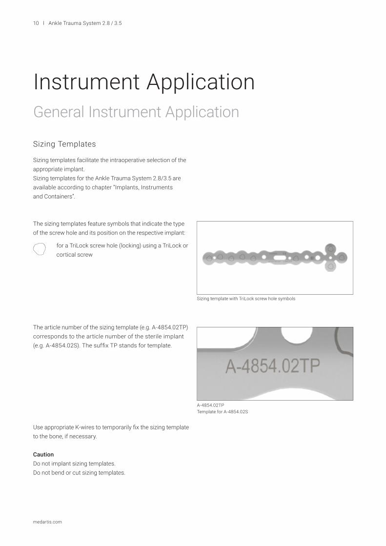
Sizing Templates
Sizing templates facilitate the intraoperative selection of the appropriate implant.Sizing templates for the Ankle Trauma System 2.8/3.5 are available according to chapter “Implants, Instruments and Containers”.
The sizing templates feature symbols that indicate the type of the screw hole and its position on the respective implant:
for a TriLock screw hole (locking) using a TriLock or cortical screw
The article number of the sizing template (e.g. A-4854.02TP) corresponds to the article number of the sterile implant (e.g. A-4854.02S). The suffix TP stands for template.
Use appropriate K-wires to temporarily fix the sizing template to the bone, if necessary.
CautionDo not implant sizing templates.Do not bend or cut sizing templates.
Sizing template with TriLock screw hole symbols
A-4854.02TPTemplate for A-4854.02S
Ankle Trauma System 2.8 / 3.5 l 11
medartis.com
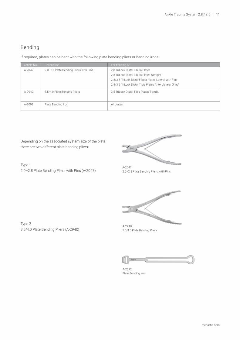
Bending
If required, plates can be bent with the following plate bending pliers or bending irons.
Article No. Description For bending of
A-2047 2.0–2.8 Plate Bending Pliers with Pins 2.8 TriLock Distal Fibula Plates
2.8 TriLock Distal Fibula Plates Straight
2.8/3.5 TriLock Distal Fibula Plates Lateral with Flap
2.8/3.5 TriLock Distal Tibia Plates Anterolateral (Flap)
A-2940 3.5/4.0 Plate Bending Pliers 3.5 TriLock Distal Tibia Plates T and L
A-2092 Plate Bending Iron All plates
A-20472.0–2.8 Plate Bending Pliers, with Pins
A-29403.5/4.0 Plate Bending Pliers
A-2092Plate Bending Iron
Depending on the associated system size of the plate there are two different plate bending pliers:
Type 1 2.0–2.8 Plate Bending Pliers with Pins (A-2047)
Type 2 3.5/4.0 Plate Bending Pliers (A-2940)
12 l Ankle Trauma System 2.8 / 3.5
medartis.com
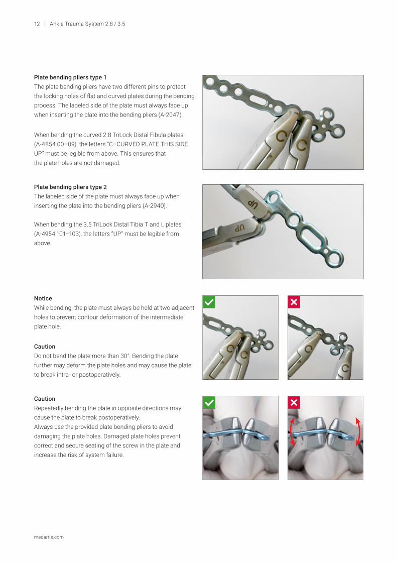
Plate bending pliers type 1The plate bending pliers have two different pins to protect the locking holes of flat and curved plates during the bending process. The labeled side of the plate must always face up when inserting the plate into the bending pliers (A-2047).
Plate bending pliers type 2The labeled side of the plate must always face up when inserting the plate into the bending pliers (A-2940).
When bending the 3.5 TriLock Distal Tibia T and L plates (A-4954.101–103), the letters “UP” must be legible from above.
Notice While bending, the plate must always be held at two adjacent holes to prevent contour deformation of the intermediate plate hole.
Caution Repeatedly bending the plate in opposite directions may cause the plate to break postoperatively. Always use the provided plate bending pliers to avoid damaging the plate holes. Damaged plate holes prevent correct and secure seating of the screw in the plate and increase the risk of system failure.
Caution Do not bend the plate more than 30°. Bending the plate further may deform the plate holes and may cause the plate to break intra- or postoperatively.
When bending the curved 2.8 TriLock Distal Fibula plates (A-4854.00–09), the letters “C–CURVED PLATE THIS SIDE UP” must be legible from above. This ensures that the plate holes are not damaged.
Ankle Trauma System 2.8 / 3.5 l 13
medartis.com
A-29502.8/3.5 Plate Holding and Positioning Instrument
Bending of Flaps
Plate Holding and Positioning
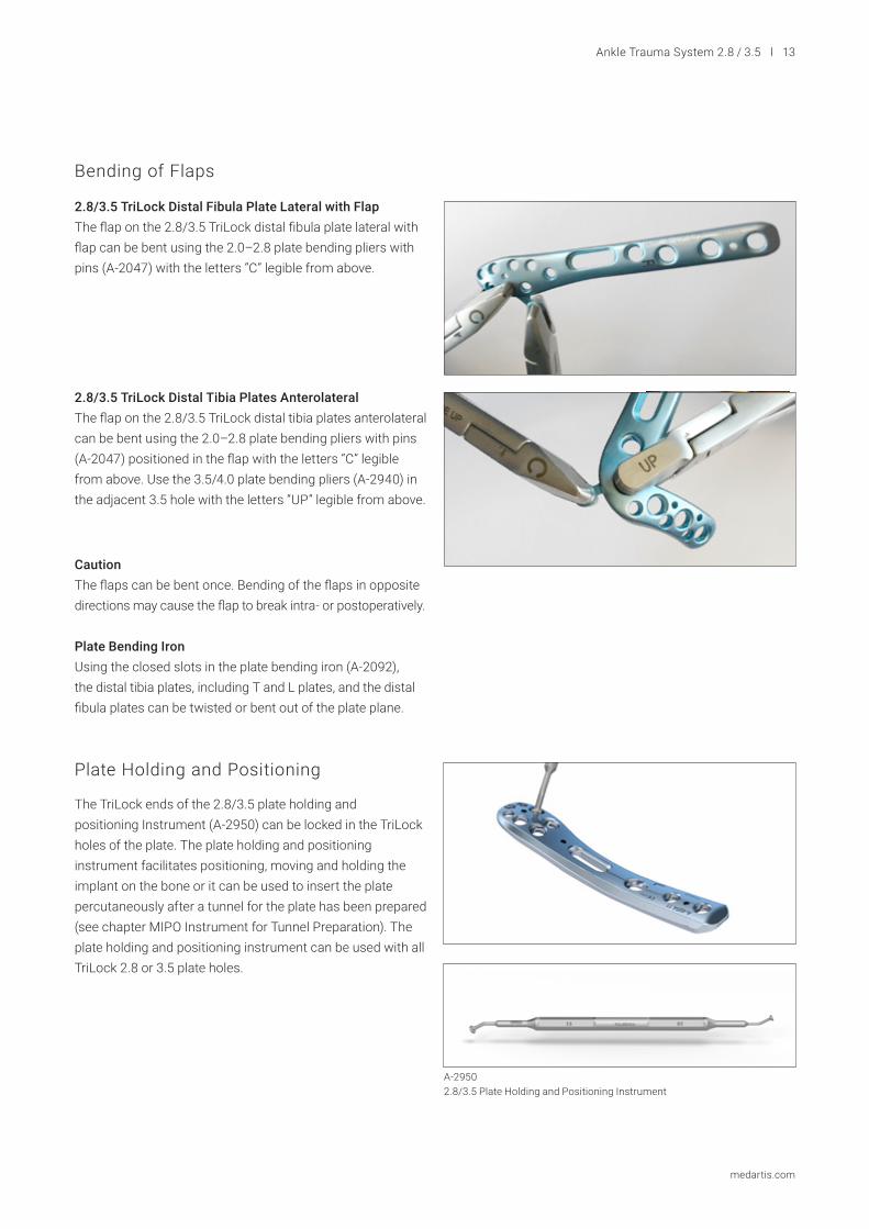
2.8/3.5 TriLock Distal Fibula Plate Lateral with FlapThe flap on the 2.8/3.5 TriLock distal fibula plate lateral with flap can be bent using the 2.0–2.8 plate bending pliers with pins (A-2047) with the letters “C” legible from above.
2.8/3.5 TriLock Distal Tibia Plates AnterolateralThe flap on the 2.8/3.5 TriLock distal tibia plates anterolateral can be bent using the 2.0–2.8 plate bending pliers with pins (A-2047) positioned in the flap with the letters “C” legible from above. Use the 3.5/4.0 plate bending pliers (A-2940) in the adjacent 3.5 hole with the letters “UP” legible from above.
Caution The flaps can be bent once. Bending of the flaps in opposite directions may cause the flap to break intra- or postoperatively.
Plate Bending Iron Using the closed slots in the plate bending iron (A-2092), the distal tibia plates, including T and L plates, and the distal fibula plates can be twisted or bent out of the plate plane.
The TriLock ends of the 2.8/3.5 plate holding and positioning Instrument (A-2950) can be locked in the TriLock holes of the plate. The plate holding and positioning instrument facilitates positioning, moving and holding the implant on the bone or it can be used to insert the plate percutaneously after a tunnel for the plate has been prepared (see chapter MIPO Instrument for Tunnel Preparation). The plate holding and positioning instrument can be used with all TriLock 2.8 or 3.5 plate holes.
14 l Ankle Trauma System 2.8 / 3.5
medartis.com
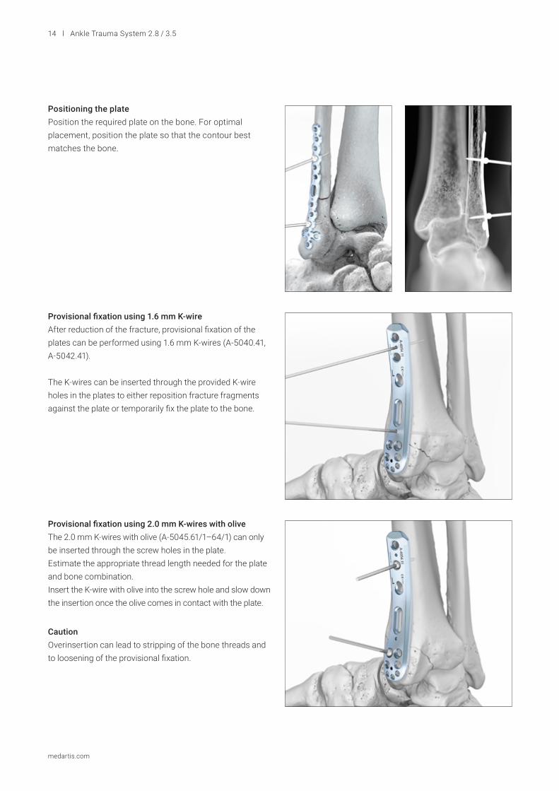
Positioning the platePosition the required plate on the bone. For optimal placement, position the plate so that the contour best matches the bone.
Provisional fixation using 1.6 mm K-wire After reduction of the fracture, provisional fixation of the plates can be performed using 1.6 mm K-wires (A-5040.41, A-5042.41).
The K-wires can be inserted through the provided K-wire holes in the plates to either reposition fracture fragments against the plate or temporarily fix the plate to the bone.
Provisional fixation using 2.0 mm K-wires with olive The 2.0 mm K-wires with olive (A-5045.61/1–64/1) can only be inserted through the screw holes in the plate. Estimate the appropriate thread length needed for the plate and bone combination.Insert the K-wire with olive into the screw hole and slow down the insertion once the olive comes in contact with the plate.
CautionOverinsertion can lead to stripping of the bone threads and to loosening of the provisional fixation.
Ankle Trauma System 2.8 / 3.5 l 15
medartis.com
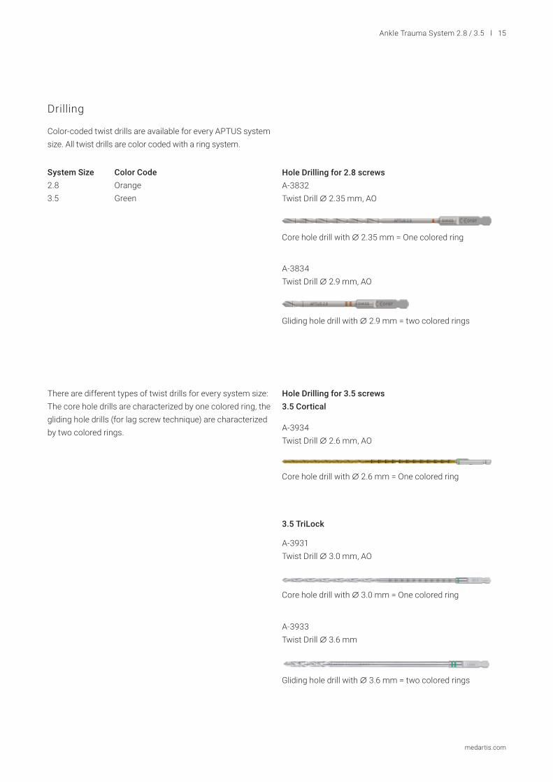
Drilling
Color-coded twist drills are available for every APTUS system size. All twist drills are color coded with a ring system.
System Size Color Code2.8 Orange3.5 Green
There are different types of twist drills for every system size: The core hole drills are characterized by one colored ring, the gliding hole drills (for lag screw technique) are characterized by two colored rings.
Core hole drill with A 2.35 mm = One colored ring
Core hole drill with A 2.6 mm = One colored ring
Core hole drill with A 3.0 mm = One colored ring
Gliding hole drill with A 3.6 mm = two colored rings
Gliding hole drill with A 2.9 mm = two colored rings
Hole Drilling for 2.8 screwsA-3832Twist Drill A 2.35 mm, AO
A-3834Twist Drill A 2.9 mm, AO
A-3934Twist Drill A 2.6 mm, AO
A-3931Twist Drill A 3.0 mm, AO
A-3933Twist Drill A 3.6 mm
Hole Drilling for 3.5 screws3.5 Cortical
3.5 TriLock
16 l Ankle Trauma System 2.8 / 3.5
medartis.com
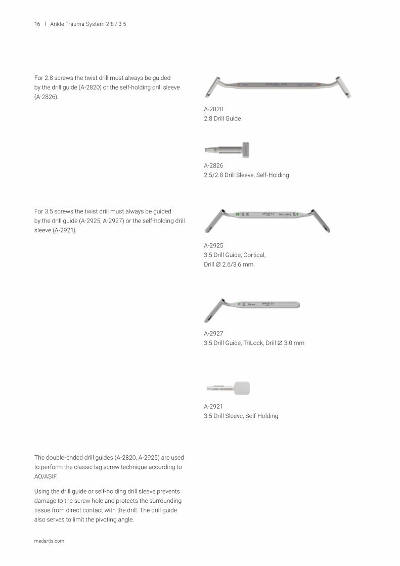
For 2.8 screws the twist drill must always be guided by the drill guide (A-2820) or the self-holding drill sleeve (A-2826).
For 3.5 screws the twist drill must always be guided by the drill guide (A-2925, A-2927) or the self-holding drill sleeve (A-2921).
The double-ended drill guides (A-2820, A-2925) are used to perform the classic lag screw technique according to AO/ASIF.
Using the drill guide or self-holding drill sleeve prevents damage to the screw hole and protects the surrounding tissue from direct contact with the drill. The drill guide also serves to limit the pivoting angle.
A-28202.8 Drill Guide
A-28262.5/2.8 Drill Sleeve, Self-Holding
A-29253.5 Drill Guide, Cortical, Drill A 2.6/3.6 mm
A-2927 3.5 Drill Guide, TriLock, Drill A 3.0 mm
A-2921 3.5 Drill Sleeve, Self-Holding
Ankle Trauma System 2.8 / 3.5 l 17
medartis.com
Compression Drill GuideThe single-ended 3.5 drill guide for compression (A-2926) is used in the compression hole of the 2.8/3.5 TriLock distal tibia plate medial and provides compression up to 3 mm across the fracture or osteotomy site.
Notice
The arrow “” indicates the direction of the compression and must always point towards the fracture/osteotomy line.
CautionFor TriLock plates ensure that the screw holes are predrilled with a pivoting angle of no more than ±15°. For this purpose, the drill guide features a limit stop of ±15°. A predrilled pivoting angle of >15° no longer allows the TriLock screws to correctly lock in the plate.
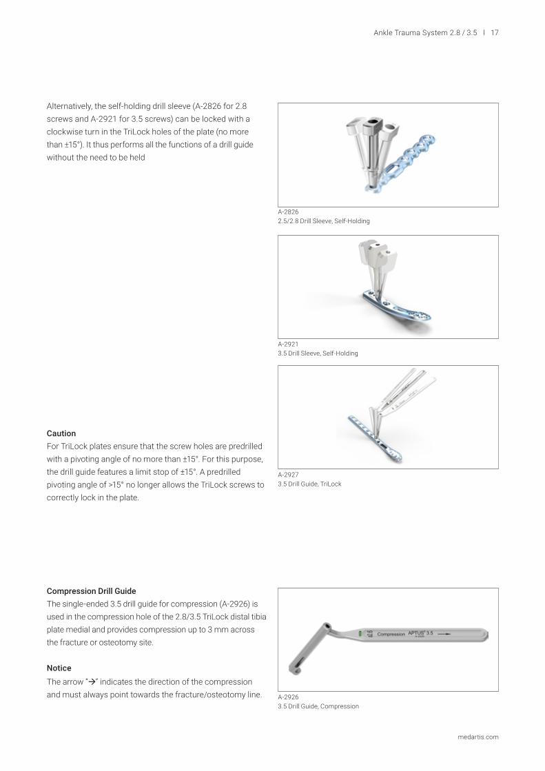
Alternatively, the self-holding drill sleeve (A-2826 for 2.8 screws and A-2921 for 3.5 screws) can be locked with a clockwise turn in the TriLock holes of the plate (no more than ±15°). It thus performs all the functions of a drill guide without the need to be held
A-29263.5 Drill Guide, Compression
A-29213.5 Drill Sleeve, Self-Holding
A-28262.5/2.8 Drill Sleeve, Self-Holding
A-29273.5 Drill Guide, TriLock

18 l Ankle Trauma System 2.8 / 3.5
medartis.com
Assigning the Screw Length
The depth gauges (A-2836, A-2931) are used to assign the ideal screw length for use in monocortical or bicortical screw fixation.
NoticeIt is important to use the correct depth gauge for the corresponding screw diameter, which is indicated on the slider and handle of the depth gauge.
Retract the slider of the depth gauge.
The depth gauge caliper has a hooked tip that is either insert-ed to the bottom of the hole or is used to catch the far cortex of the bone. When using the depth gauge, the caliper stays static, only the slider is adjusted.
To assign the screw length, place the end of the slider onto the plate or directly onto the bone. When using the lag screw technique, place the end of the slider directly onto the bone.
The ideal screw length for the assigned drill hole can be read on the scale of the depth gauge.
When inserting a 3.5 cortical screw, the screw length may also be assigned directly from the scale on the twist drill A 2.6 mm (A-3934) in combination with the drill guide (A-2925). The length is assigned from the end of the drill guide.
A-28362.8 Depth Gauge
A-20132.5/2.8 Screwdriver Blade, HD7, AO
A-2911 3.5/4.0 Screwdriver Blade, HD15, AO
Both the 2.8 screwdriver blade (A-2013) and the 3.5 screwdriver blade (A-2911) feature the patented HexaDrive self-holding system.
Screw Pick-Up
A-29313.5/4.0 Depth Gauge, 10–70 mm
Ankle Trauma System 2.8 / 3.5 l 19
medartis.com
Picture 30Platzhalter
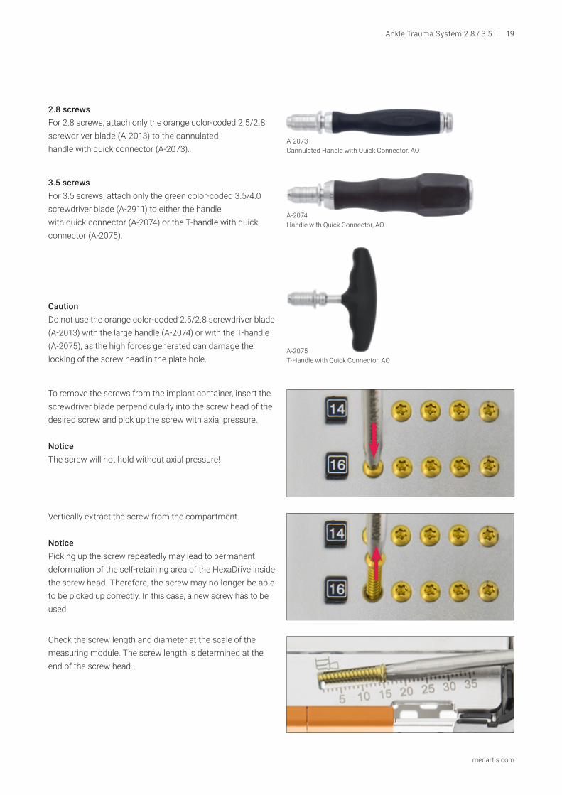
2.8 screwsFor 2.8 screws, attach only the orange color-coded 2.5/2.8 screwdriver blade (A-2013) to the cannulated handle with quick connector (A-2073).
CautionDo not use the orange color-coded 2.5/2.8 screwdriver blade (A-2013) with the large handle (A-2074) or with the T-handle (A-2075), as the high forces generated can damage the locking of the screw head in the plate hole.
To remove the screws from the implant container, insert the screwdriver blade perpendicularly into the screw head of the desired screw and pick up the screw with axial pressure.
NoticeThe screw will not hold without axial pressure!
Vertically extract the screw from the compartment.
NoticePicking up the screw repeatedly may lead to permanent deformation of the self-retaining area of the HexaDrive inside the screw head. Therefore, the screw may no longer be able to be picked up correctly. In this case, a new screw has to be used.
Check the screw length and diameter at the scale of the measuring module. The screw length is determined at the end of the screw head.
A-2073Cannulated Handle with Quick Connector, AO
A-2074 Handle with Quick Connector, AO
A-2075T-Handle with Quick Connector, AO
3.5 screwsFor 3.5 screws, attach only the green color-coded 3.5/4.0 screwdriver blade (A-2911) to either the handle with quick connector (A-2074) or the T-handle with quick connector (A-2075).
20 l Ankle Trauma System 2.8 / 3.5
medartis.com
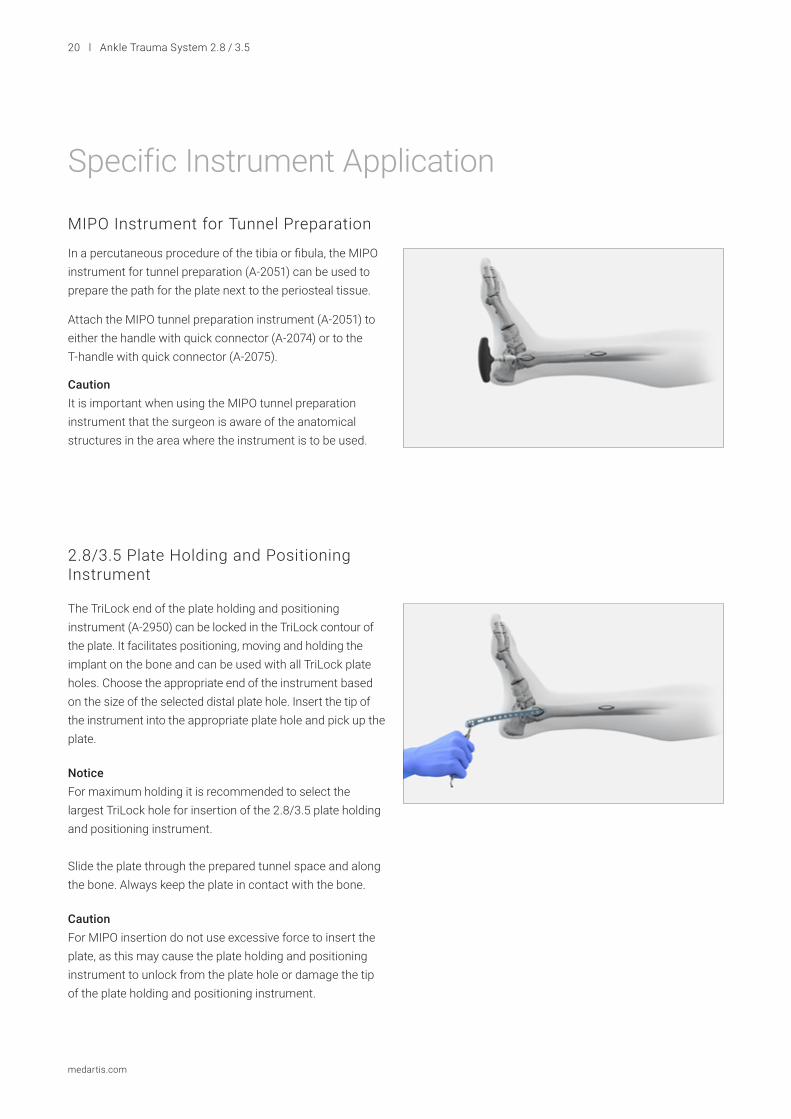
In a percutaneous procedure of the tibia or fibula, the MIPO instrument for tunnel preparation (A-2051) can be used to prepare the path for the plate next to the periosteal tissue.
Attach the MIPO tunnel preparation instrument (A-2051) to either the handle with quick connector (A-2074) or to the T-handle with quick connector (A-2075).
Caution It is important when using the MIPO tunnel preparation instrument that the surgeon is aware of the anatomical structures in the area where the instrument is to be used.
The TriLock end of the plate holding and positioning instrument (A-2950) can be locked in the TriLock contour of the plate. It facilitates positioning, moving and holding the implant on the bone and can be used with all TriLock plate holes. Choose the appropriate end of the instrument based on the size of the selected distal plate hole. Insert the tip of the instrument into the appropriate plate hole and pick up the plate.
NoticeFor maximum holding it is recommended to select the largest TriLock hole for insertion of the 2.8/3.5 plate holding and positioning instrument.
Slide the plate through the prepared tunnel space and along the bone. Always keep the plate in contact with the bone.
CautionFor MIPO insertion do not use excessive force to insert the plate, as this may cause the plate holding and positioning instrument to unlock from the plate hole or damage the tip of the plate holding and positioning instrument.
2.8/3.5 Plate Holding and Positioning Instrument
Specific Instrument Application
MIPO Instrument for Tunnel Preparation
Ankle Trauma System 2.8 / 3.5 l 21
medartis.com
Insert the 3.5 drill guide for compression (A-2926) into the 3.5 compression hole of the 2.8/3.5 medial distal tibia plate.The drill guide is used together with the twist drill A 2.6 mm (A-3934) for 3.5 cortical screws.
Up to 3 mm of compression can be achieved through the compression hole.
NoticeThe arrow on the drill guide indicates the direction of the compression and must always point towards the fracture/osteotomy line.
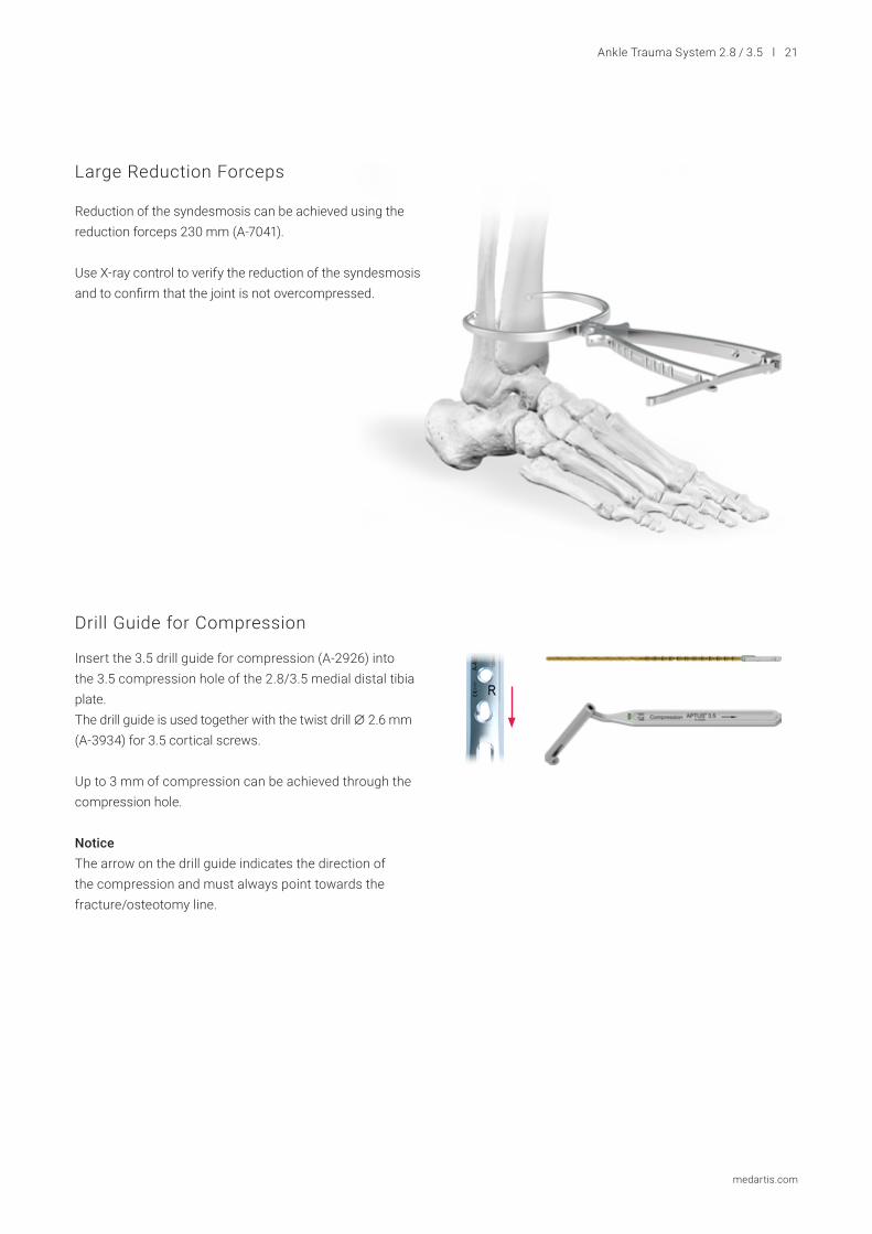
Large Reduction Forceps
Drill Guide for Compression
Reduction of the syndesmosis can be achieved using the reduction forceps 230 mm (A-7041).
Use X-ray control to verify the reduction of the syndesmosis and to confirm that the joint is not overcompressed.
22 l Ankle Trauma System 2.8 / 3.5
medartis.com
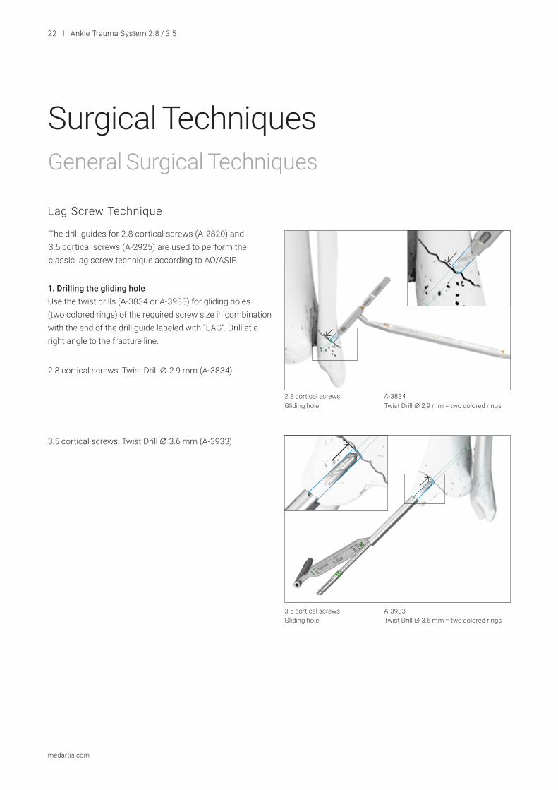
1. Drilling the gliding hole Use the twist drills (A-3834 or A-3933) for gliding holes (two colored rings) of the required screw size in combination with the end of the drill guide labeled with "LAG". Drill at a right angle to the fracture line.
2.8 cortical screws: Twist Drill A 2.9 mm (A-3834)
3.5 cortical screws: Twist Drill A 3.6 mm (A-3933)
Surgical TechniquesGeneral Surgical Techniques
Lag Screw Technique
The drill guides for 2.8 cortical screws (A-2820) and 3.5 cortical screws (A-2925) are used to perform the classic lag screw technique according to AO/ASIF.
A-3834Twist Drill A 2.9 mm = two colored rings
A-3933Twist Drill A 3.6 mm = two colored rings
2.8 cortical screwsGliding hole
3.5 cortical screwsGliding hole
Ankle Trauma System 2.8 / 3.5 l 23
medartis.com
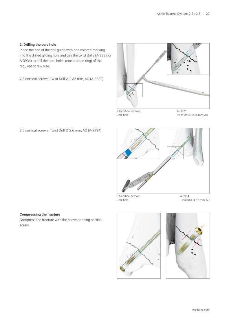
2. Drilling the core hole Place the end of the drill guide with one colored marking into the drilled gliding hole and use the twist drills (A-3832 or A-3934) to drill the core holes (one colored ring) of the required screw size.
2.8 cortical screws: Twist Drill A 2.35 mm, AO (A-3832)
3.5 cortical screws: Twist Drill A 2.6 mm, AO (A-3934)
Compressing the fracture Compress the fracture with the corresponding cortical screw.
A-3832Twist Drill A 2.35 mm, AO
2.8 cortical screwsCore hole
A-3934Twist Drill A 2.6 mm, AO
3.5 cortical screwsCore hole
24 l Ankle Trauma System 2.8 / 3.5
medartis.com
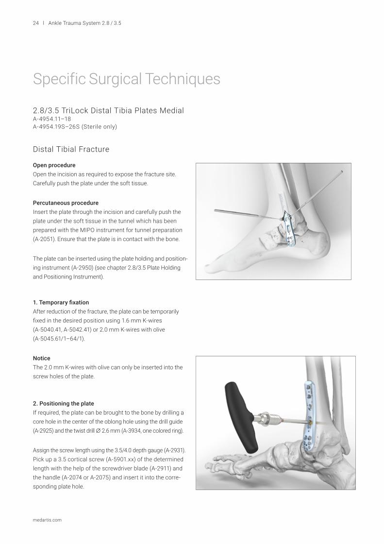
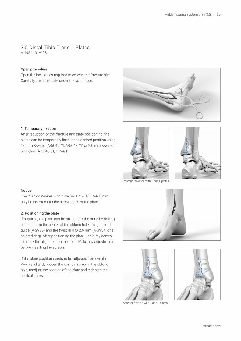
Open procedureOpen the incision as required to expose the fracture site. Carefully push the plate under the soft tissue.
Percutaneous procedureInsert the plate through the incision and carefully push the plate under the soft tissue in the tunnel which has been prepared with the MIPO instrument for tunnel preparation (A-2051). Ensure that the plate is in contact with the bone.
1. Temporary fixationAfter reduction of the fracture, the plate can be temporarily fixed in the desired position using 1.6 mm K-wires (A-5040.41, A-5042.41) or 2.0 mm K-wires with olive (A-5045.61/1–64/1).
NoticeThe 2.0 mm K-wires with olive can only be inserted into the screw holes of the plate.
2. Positioning the plate If required, the plate can be brought to the bone by drilling a core hole in the center of the oblong hole using the drill guide (A-2925) and the twist drill A 2.6 mm (A-3934, one colored ring).
Assign the screw length using the 3.5/4.0 depth gauge (A-2931). Pick up a 3.5 cortical screw (A-5901.xx) of the determined length with the help of the screwdriver blade (A-2911) and the handle (A-2074 or A-2075) and insert it into the corre-sponding plate hole.
Specific Surgical Techniques
2.8/3.5 TriLock Distal Tibia Plates MedialA-4954.11–18 A-4954.19S–26S (Sterile only)
Distal Tibial Fracture
The plate can be inserted using the plate holding and position-ing instrument (A-2950) (see chapter 2.8/3.5 Plate Holding and Positioning Instrument).
Ankle Trauma System 2.8 / 3.5 l 25
medartis.com
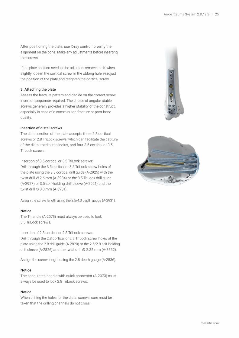
3. Attaching the plateAssess the fracture pattern and decide on the correct screw insertion sequence required. The choice of angular stable screws generally provides a higher stability of the construct, especially in case of a comminuted fracture or poor bone quality.
Insertion of distal screwsThe distal section of the plate accepts three 2.8 cortical screws or 2.8 TriLock screws, which can facilitate the capture of the distal medial malleolus, and four 3.5 cortical or 3.5 TriLock screws.
Insertion of 3.5 cortical or 3.5 TriLock screws:Drill through the 3.5 cortical or 3.5 TriLock screw holes of the plate using the 3.5 cortical drill guide (A-2925) with the twist drill A 2.6 mm (A-3934) or the 3.5 TriLock drill guide (A-2927) or 3.5 self-holding drill sleeve (A-2921) and the twist drill A 3.0 mm (A-3931).
Assign the screw length using the 3.5/4.0 depth gauge (A-2931).
Notice The T-handle (A-2075) must always be used to lock 3.5 TriLock screws.
NoticeThe cannulated handle with quick connector (A-2073) must always be used to lock 2.8 TriLock screws.
Notice When drilling the holes for the distal screws, care must be taken that the drilling channels do not cross.
Insertion of 2.8 cortical or 2.8 TriLock screws:Drill through the 2.8 cortical or 2.8 TriLock screw holes of the plate using the 2.8 drill guide (A-2820) or the 2.5/2.8 self-holding drill sleeve (A-2826) and the twist drill A 2.35 mm (A-3832).
Assign the screw length using the 2.8 depth gauge (A-2836).
After positioning the plate, use X-ray control to verify the alignment on the bone. Make any adjustments before inserting the screws.
If the plate position needs to be adjusted: remove the K-wires, slightly loosen the cortical screw in the oblong hole, readjust the position of the plate and retighten the cortical screw.
26 l Ankle Trauma System 2.8 / 3.5
medartis.com
4. Filling the remaining screw holes Fill the remaining screw holes preferably with 2.8 or 3.5 TriLock screws (A-5850.xx or A-5950.xx) or with 2.8 or 3.5 cortical screws (A-5800.xx or A-5901.xx) as indicated by the type of fracture.
NoticeMake sure correct locking has been achieved (see chapter TriLock Locking Technology).
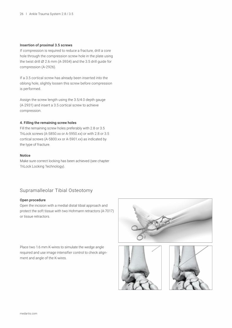
Open procedureOpen the incision with a medial distal tibial approach and protect the soft tissue with two Hohmann retractors (A-7017) or tissue retractors.
Place two 1.6 mm K-wires to simulate the wedge angle required and use image intensifier control to check align-ment and angle of the K-wires.
Insertion of proximal 3.5 screwsIf compression is required to reduce a fracture, drill a core hole through the compression screw hole in the plate using the twist drill A 2.6 mm (A-3934) and the 3.5 drill guide for compression (A-2926).
If a 3.5 cortical screw has already been inserted into the oblong hole, slightly loosen this screw before compression is performed.
Assign the screw length using the 3.5/4.0 depth gauge (A-2931) and insert a 3.5 cortical screw to achieve compression.
Supramalleolar Tibial Osteotomy
Ankle Trauma System 2.8 / 3.5 l 27
medartis.com
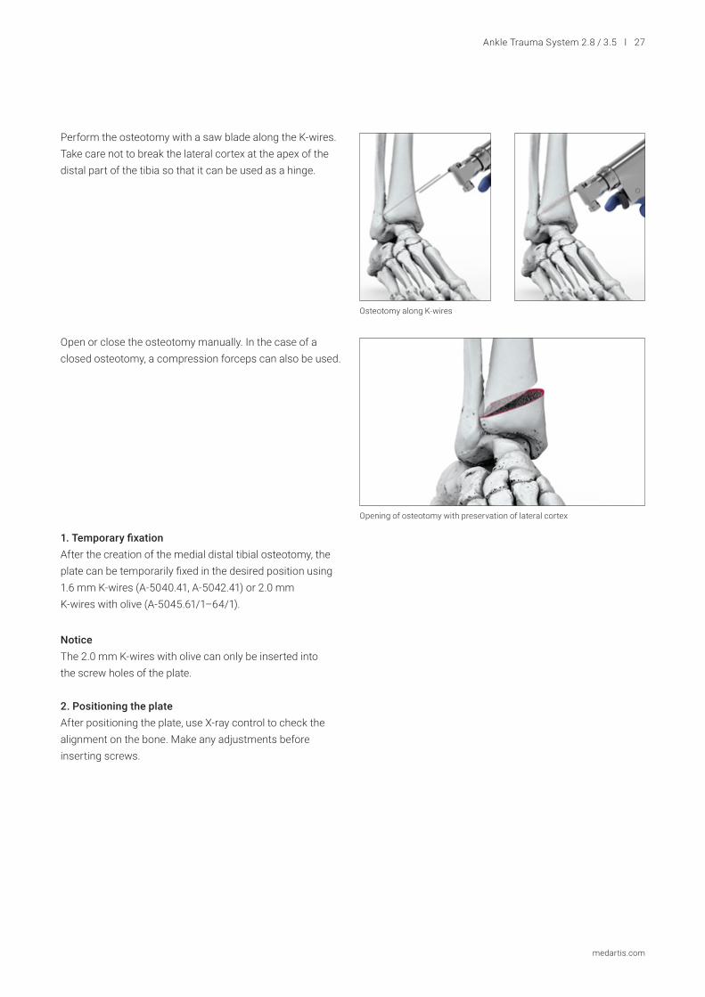
Perform the osteotomy with a saw blade along the K-wires. Take care not to break the lateral cortex at the apex of the distal part of the tibia so that it can be used as a hinge.
Open or close the osteotomy manually. In the case of a closed osteotomy, a compression forceps can also be used.
1. Temporary fixation After the creation of the medial distal tibial osteotomy, the plate can be temporarily fixed in the desired position using 1.6 mm K-wires (A-5040.41, A-5042.41) or 2.0 mm K-wires with olive (A-5045.61/1–64/1).
Notice The 2.0 mm K-wires with olive can only be inserted into the screw holes of the plate.
2. Positioning the plateAfter positioning the plate, use X-ray control to check the alignment on the bone. Make any adjustments before inserting screws.
Osteotomy along K-wires
Opening of osteotomy with preservation of lateral cortex
28 l Ankle Trauma System 2.8 / 3.5
medartis.com
3. Attaching the plateInsertion of distal 3.5 TriLock screws: In a supramalleolar osteotomy it is recommended to insert 3.5 TriLock screws in the distal section of the plate first.
Drill the 3.5 TriLock screw holes of the plate using the 3.5 TriLock drill guide (A-2927) or the 3.5 self-holding drill sleeve (A-2921) and the twist drill A 3.0 mm (A-3931).
Assign the screw length using the 3.5/4.0 depth gauge (A-2931).
Notice The T-handle (A-2075) must always be used to lock 3.5 TriLock screws.
Insertion of proximal 3.5 screws:If compression is required to reduce the osteotomy, drill through the compression screw hole in the plate using the A 2.6 mm twist drill (A-3934) and the 3.5 drill guide for compression (A-2926).
Assign the screw length using the 3.5/4.0 depth gauge (A-2931) and insert a 3.5 cortical screw to achieve compression.
4. Filling the remaining screw holesFill the remaining screw holes preferably with 3.5 TriLock screws (A-5950.xx).
NoticeMake sure correct locking has been achieved (see chapter TriLock Locking Technology).
Ankle Trauma System 2.8 / 3.5 l 29
medartis.com
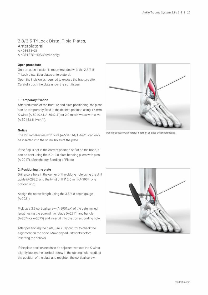
Open procedureOnly an open incision is recommended with the 2.8/3.5 TriLock distal tibia plates anterolateral.Open the incision as required to expose the fracture site. Carefully push the plate under the soft tissue.
1. Temporary fixationAfter reduction of the fracture and plate positioning, the plate can be temporarily fixed in the desired position using 1.6 mm K-wires (A-5040.41, A-5042.41) or 2.0 mm K-wires with olive (A-5045.61/1–64/1).
NoticeThe 2.0 mm K-wires with olive (A-5045.61/1 -64/1) can only be inserted into the screw holes of the plate.
If the flap is not in the correct position or flat on the bone, it can be bent using the 2.0–2.8 plate bending pliers with pins (A-2047). (See chapter Bending of Flaps)
Assign the screw length using the 3.5/4.0 depth gauge (A-2931).
Pick up a 3.5 cortical screw (A-5901.xx) of the determined length using the screwdriver blade (A-2911) and handle (A-2074 or A-2075) and insert it into the corresponding hole.
After positioning the plate, use X-ray control to check the alignment on the bone. Make any adjustments before inserting the screws.
If the plate position needs to be adjusted: remove the K-wires, slightly loosen the cortical screw in the oblong hole, readjust the position of the plate and retighten the cortical screw.
2.8/3.5 TriLock Distal Tibia Plates, AnterolateralA-4954.31–36A-4954.37S–40S (Sterile only)
Open procedure with careful insertion of plate under soft tissue.
2. Positioning the plateDrill a core hole in the center of the oblong hole using the drill guide (A-2925) and the twist drill A 2.6 mm (A-3934, one colored ring).
30 l Ankle Trauma System 2.8 / 3.5
medartis.com
3. Attaching the plateAsses the fracture pattern and decide on the correct screw insertion sequence required.The choice of angular stable screws generally provides a higher stability of the construct, especially in case of a comminuted fracture or poor bone quality.
Insertion of distal screwsThe distal section of the plate accepts four 2.8 cortical screws or 2.8 TriLock screws and four 3.5 cortical screws or 3.5 TriLock screws, which facilitate an intersecting scaffold (rafting) to support the distal articular surface.
Notice The T-handle (A-2075) must always be used to lock 3.5 TriLock screws.
Notice When drilling the holes for the distal screws, care must be taken that the drilling channels do not cross.
Insertion of 3.5 cortical or 3.5 TriLock screws:Drill through the 3.5 cortical or 3.5 TriLock screw holes of the plate using the 3.5 cortical drill guide (A-2925) with the twist drill A 2.6 mm (A-3934) or the 3.5 TriLock drill guide (A-2927) or 3.5 self-holding drill sleeve (A-2921) and the twist drill A 3.0 mm (A-3931).
Assign the screw length using the 3.5/4.0 depth gauge (A-2931).
Insertion of 2.8 TriLock screws:Drill through the 2.8 cortical or 2.8 TriLock screw holes of the plate using the 2.8 drill guide (A-2820) or the 2.5/2.8 self-holding drill sleeve (A-2826) and the twist drill A 2.35 mm (A-3832).
Assign the screw length using the 2.8 depth gauge (A-2836).
NoticeThe cannulated handle with quick connector (A-2073) must always be used to lock 2.8 TriLock screws.
Ankle Trauma System 2.8 / 3.5 l 31
medartis.com
Insertion of proximal 3.5 screwsThe proximal section of the plate accepts 3.5 cortical or 3.5 TriLock screws.
Insertion of 3.5 cortical or 3.5 TriLock screws:Drill through the 3.5 cortical or 3.5 TriLock screw holes of the plate using the 3.5 cortical drill guide (A-2925) with the twist drill A 2.6 mm (A-3934) or the 3.5 TriLock drill guide (A-2927) or 3.5 self-holding drill sleeve (A-2921) and the twist drill A 3.0 mm (A-3931).
Assign the screw length using the 3.5/4.0 depth gauge (A-2931).
4. Filling the remaining screw holesFill the remaining screw holes preferably with 2.8 or 3.5 TriLock screws (A-5850.xx or A-5950.xx) or 2.8 or 3.5 cortical screws (A-5800.xx or A-5901.xx) as indicated by the type of fracture.
NoticeMake sure correct locking has been achieved (see chapter TriLock Locking Technology).
32 l Ankle Trauma System 2.8 / 3.5
medartis.com
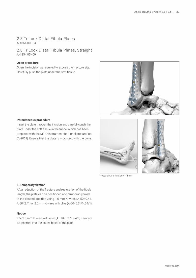
Open procedureOpen the incision as required to expose the fracture site. Carefully push the plate under the soft tissue.
Percutaneous procedureInsert the plate through the incision and carefully push the plate under the soft tissue in the tunnel which has been prepared with the MIPO instrument for tunnel preparation (A-2051). Ensure that the plate is in contact with the bone.
The plate can be inserted using the plate holding and positioning instrument (A-2950) (see chapter 2.8/3.5 Plate Holding and Positioning Instrument).
NoticeThe 2.0 mm K-wires with olive (A-5045.61/1 -64/1) can only be inserted into the screw holes of the plate.
2. Positioning the plateAfter positioning the plate, use X-ray control to check the alignment on the bone. Make any adjustments before inserting the screws.
1. Temporary fixation After reduction of the fracture, the plate can be positioned and temporarily fixed in the desired position using 1.6 mm K-wires (A-5040.41, A-5042.41) or 2.0 mm K-wires with olive (A-5045.61/1-64/1).
2.8/3.5 TriLock Distal Fibula Plates, LateralA-4954.00–05A-4954.06S–09S (Sterile only)
Distal Fibula Fracture
Ankle Trauma System 2.8 / 3.5 l 33
medartis.com
3. Attaching the plateAssess the fracture pattern and decide on the correct screw insertion sequence required.
The choice of angular stable screws generally provides a higher stability of the construct, especially in case of a comminuted fracture or poor bone quality.
Insertion of distal screwsThe distal section of the plates with/without flap accept nine/eight 2.8 cortical or 2.8 TriLock screws respectively.
Insertion of 2.8 cortical or 2.8 TriLock screws:Drill through the 2.8 cortical or 2.8 TriLock screw holes of the plate using the 2.8 drill guide (A-2820) or the 2.5/2.8 self-holding drill sleeve (A-2826) and the twist drill A 2.35 mm (A-3832). Assign the screw length using the 2.8 depth gauge (A-2836).
NoticeThe cannulated handle with quick connector (A-2073) must always be used to lock 2.8 TriLock screws.
Notice When drilling the holes for the distal screws, care must be taken that the drilling channels do not cross.
2.8/3.5 TriLock Distal Fibula Plates, Lateral, with FlapA-4954.51–54
If the flap is not in the correct position to treat the Wagstaffe fracture, or is not flat on the bone, it can be bent using the 2.0-2.8 plate bending pliers with pins (A-2047). (See chapter Bending of Flaps)
Anterior tibiofibular ligamentFlap with 2.8 TriLock screw holding the Wagstaffe fragment
34 l Ankle Trauma System 2.8 / 3.5
medartis.com
Insertion of proximal 3.5 screwsThe proximal section of the plates accepts 3.5 cortical or 3.5 TriLock screws.
Insertion of 3.5 cortical or 3.5 TriLock screws:Drill through the 3.5 cortical or 3.5 TriLock screw holes of the plate using the 3.5 cortical drill guide (A-2925) with the twist drill A 2.6 mm (A-3934) or the 3.5 TriLock drill guide (A-2927) or 3.5 self-holding drill sleeve (A-2921) and the twist drill A 3.0 mm (A-3931).
Assign the screw length using the 3.5/4.0 depth gauge (A-2931).
Notice The T-handle (A-2075) must always be used to lock 3.5 TriLock screws.
4. Filling the remaining screw holes Fill the remaining screw holes preferably with 2.8 or 3.5 TriLock screws (A-5850.xx or A-5950.xx) or with 2.8 or 3.5 cortical screws (A-5800.xx or A-5901.xx) as indicated by the type of fracture.
NoticeMake sure correct locking has been achieved (see chapter TriLock Locking Technology).
Ankle Trauma System 2.8 / 3.5 l 35
medartis.com
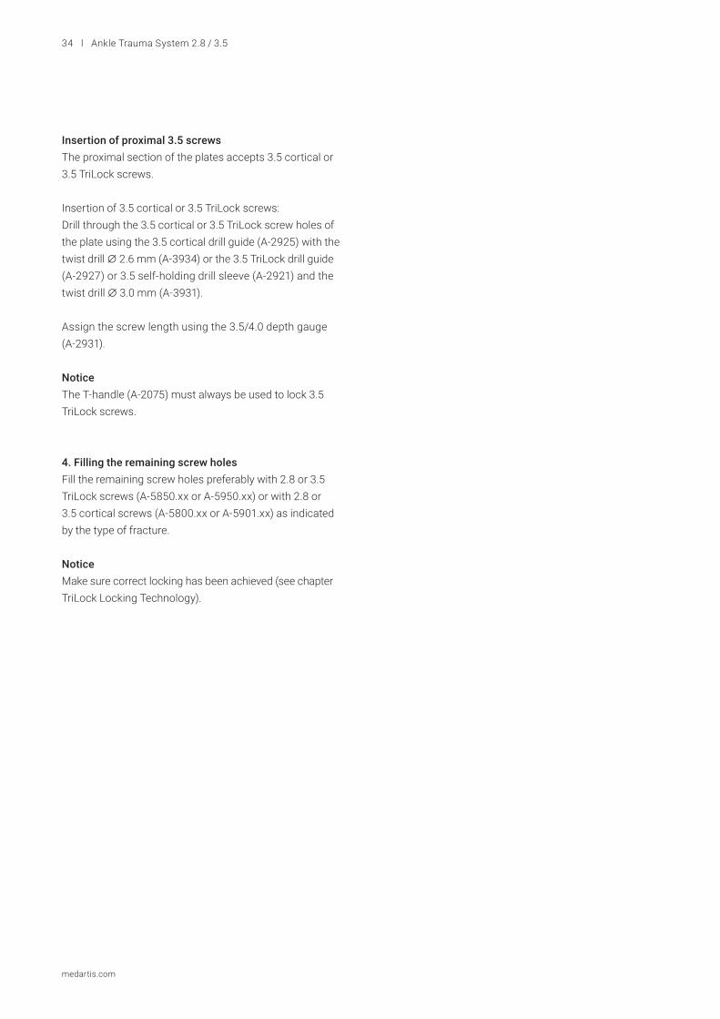
Distal Fibula Osteotomy
Open procedureOpen with a lateral approach respecting any former incisions or wounds. Protect the soft tissue with two Hohmann retractors (A-7017) or tissue retractors.
The osteotomy of the fibula can be performed with an oblique or Z-shaped cut. Once the osteotomy has been performed, correct the length, rotation and abduction of the lateral malleolus as needed.
Oblique or Z shaped osteotomy can be performed
1. Temporary fixationAfter performing a distal fibula osteotomy, the plate can be positioned and temporarily fixed using 1.6 mm K-wires (A-5040.41, A-5042.41) or 2.0 mm K-wires with olive (A-5045.61/1 -64/1).
After provisional fixation, use X-ray control to check that the osteotomy has achieved the correct length, rotation or adduction of the fibula as required.
NoticeThe 2.0 mm K-wires with olive (A-5045.61/1–64/1) can only be inserted into the screw holes of the plate.
2. Attaching the plateIn a distal fibula osteotomy, it is recommended to use angular stable screws both distally and proximally as they generally provide a higher stability of the construct, especially in case of poor bone quality.
36 l Ankle Trauma System 2.8 / 3.5
medartis.com
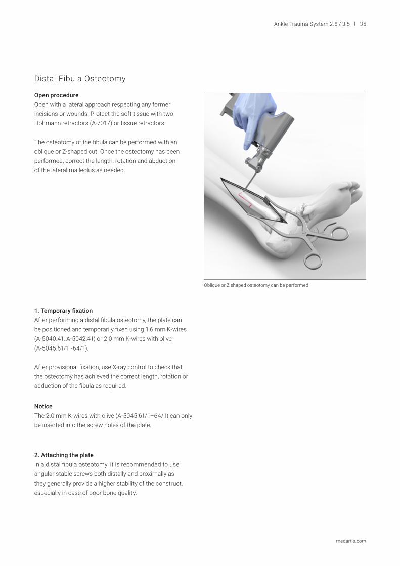
Syndesmotic FixationAfter fibular reconstruction is achieved, tibiofibular instability is determined and the decision whether or not to fix the syndesmosis is made. The decision can be made preopera-tively using radiographs or intraoperatively through a series of syndesmotic stress tests.
Syndesmotic reduction is achieved using the reduction forceps (A-7041).
The 2.8/3.5 TriLock distal fibula plates lateral (A-4954.00–09S, A-4954.51–54) feature two options for syndesmotic fixation:
- Single syndesmotic hole with 20° angulation to allow for the proper drill angle of a syndesmotic screw or suture button implant.
- Oblong hole with 20° angulation to allow for the proper drill angle into the center of the distal tibia for one or two 3.5 cortical screws (A-5901.10/1–60/1).
NoticeSuture button implants cannot be used in the oblong hole and will fall through at certain angulations.
One or two 3.5 cortical screws (A-5901.xx) are placed through the fibula to the medial side of the tibia, achieving four points of cortical fixation. Due to the angulation of the syndesmotic holes, the screws run at an anterior trajectory and parallel to the ankle joint. These screws are placed with the intent of no compression (i. e. no lag screw technique is used).
NoticeIt is not recommended to use 2.8 cortical screws in the single or oblong syndesmotic hole as the screwhead diameter is too small and the screw will fall through the oblong hole.
Proper level of syndesmotic screw The first screw is placed approximately 1 cm proximal to the syndesmosis or 4 cm proximal to the ankle joint.
Ankle Trauma System 2.8 / 3.5 l 37
medartis.com
2.8 TriLock Distal Fibula PlatesA-4854.00–04
2.8 TriLock Distal Fibula Plates, StraightA-4854.05–09
Open procedureOpen the incision as required to expose the fracture site. Carefully push the plate under the soft tissue.
Percutaneous procedureInsert the plate through the incision and carefully push the plate under the soft tissue in the tunnel which has been prepared with the MIPO instrument for tunnel preparation (A-2051). Ensure that the plate is in contact with the bone.
1. Temporary fixationAfter reduction of the fracture and restoration of the fibula length, the plate can be positioned and temporarily fixed in the desired position using 1.6 mm K-wires (A-5040.41, A-5042.41) or 2.0 mm K-wires with olive (A-5045.61/1-.64/1).
NoticeThe 2.0 mm K-wires with olive (A-5045.61/1-64/1) can only be inserted into the screw holes of the plate.
Posterolateral fixation of fibula
38 l Ankle Trauma System 2.8 / 3.5
medartis.com
3. Attaching the plateAssess the fracture pattern and decide on the correct screw insertion sequence required.
The choice of angular stable screws generally provides a higher stability of the construct, especially in case of a comminuted fracture or poor bone quality.
Insertion of 2.8 cortical or 2.8 TriLock screwsDrill through the 2.8 cortical or 2.8 TriLock screw holes of the plate using the 2.8 drill guide (A-2820) or the 2.5/2.8 self-holding drill sleeve (A-2826) and the twist drill A 2.35 mm (A-3832).
Assign the screw length using the 2.8 depth gauge (A-2836).
Notice The cannulated handle with quick connector (A-2073) must always be used to lock 2.8 TriLock screws.
4. Filling the remaining screw holesFill the remaining screw holes with 2.8 TriLock screws (A-5850.xx) or 2.8 cortical screws (A-5800.xx) as indicated by the type of fracture.
NoticeMake sure correct locking has been achieved (see chapter TriLock Locking Technology).
2. Positioning the plateIf required, the plate can be brought to the bone by drilling a core hole in the center of the oblong hole using the drill guide (A-2820) and the twist drill A 2.35 mm (A-3832, one colored ring). After positioning the plate, use X-ray control to check the alignment on the bone. Make any adjustments before inserting the screws.
If the plate position needs to be adjusted: remove the K-wires, slightly loosen the cortical screw in the oblong hole, readjust the position of the plate and retighten the cortical screw.
Posterior fixation with T and L plates
Ankle Trauma System 2.8 / 3.5 l 39
medartis.com
3.5 Distal Tibia T and L Plates A-4954.101–103
Open procedureOpen the incision as required to expose the fracture site. Carefully push the plate under the soft tissue.
1. Temporary fixationAfter reduction of the fracture and plate positioning, the plates can be temporarily fixed in the desired position using 1.6 mm K-wires (A-5040.41, A-5042.41) or 2.0 mm K-wires with olive (A-5045.61/1–64/1).
NoticeThe 2.0 mm K-wires with olive (A-5045.61/1–64/1) can only be inserted into the screw holes of the plate.
2. Positioning the plateIf required, the plate can be brought to the bone by drilling a core hole in the center of the oblong hole using the drill guide (A-2925) and the twist drill A 2.6 mm (A-3934, one colored ring). After positioning the plate, use X-ray control to check the alignment on the bone. Make any adjustments before inserting the screws.
If the plate position needs to be adjusted: remove the K-wires, slightly loosen the cortical screw in the oblong hole, readjust the position of the plate and retighten the cortical screw.
Anterior fixation with T and L plates
40 l Ankle Trauma System 2.8 / 3.5
medartis.com
3. Attaching the plateAssess the fracture pattern and decide on the correct screw insertion sequence required.
The choice of angular stable screws generally provides a higher stability of the construct, especially in case of a comminuted fracture or poor bone quality.
Insertion of 3.5 cortical or 3.5 TriLock screwsThe distal screw hole trajectories are angled superiorly, with the intention to avoid the joint space.
Drill through the 3.5 cortical or 3.5 TriLock screw holes of the plate using the 3.5 cortical drill guide (A-2925) with the twist drill A 2.6 mm (A-3934) or the 3.5 TriLock drill guide (A-2927) or 3.5 self-holding drill sleeve (A-2921) and the twist drill A 3.0 mm (A-3931).
Assign the screw length using the 3.5/4.0 depth gauge (A-2931).
NoticeThe T-handle (A-2075) must always be used to lock 3.5 TriLock screws.
4. Filling the remaining screw holesFill the remaining screw holes preferably with 2.8 or 3.5 TriLock screws (A-5850.xx or A-5950.xx) or with 2.8 or 3.5 cortical screws (A-5800.xx or A-5901.xx) as indicated by the type of fracture.
NoticeMake sure correct locking has been achieved (see chapter TriLock Locking Technology).
Ankle Trauma System 2.8 / 3.5 l 41
medartis.com
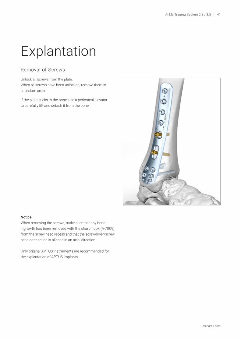
ExplantationRemoval of Screws
Unlock all screws from the plate.When all screws have been unlocked, remove them in a random order.
If the plate sticks to the bone, use a periosteal elevator to carefully lift and detach it from the bone.
Notice When removing the screws, make sure that any bone ingrowth has been removed with the sharp hook (A-7009) from the screw head recess and that the screwdriver/screw head connection is aligned in an axial direction.
Only original APTUS instruments are recommended for the explantation of APTUS implants.
Insertion Torque MIn
Locking Torque MLock
Insertion Phase
ARelease
BLocking
C
Torq
ue M
Rotational Angle α
42 l Ankle Trauma System 2.8 / 3.5
medartis.com
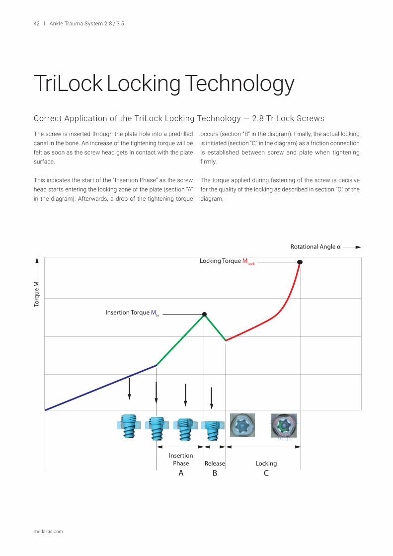
TriLock Locking TechnologyCorrect Application of the TriLock Locking Technology — 2.8 TriLock Screws
The screw is inserted through the plate hole into a predrilled canal in the bone. An increase of the tightening torque will be felt as soon as the screw head gets in contact with the plate surface.
This indicates the start of the “Insertion Phase” as the screw head starts entering the locking zone of the plate (section “A” in the diagram). Afterwards, a drop of the tightening torque
occurs (section “B” in the diagram). Finally, the actual locking is initiated (section “C” in the diagram) as a friction connection is established between screw and plate when tightening firmly.
The torque applied during fastening of the screw is decisive for the quality of the locking as described in section “C” of the diagram.
InsertionPhase
B
ContactTorque
ARelease
CLocking
D
Rotational Angle α
Locking Torque MLock
Torq
ue M
Insertion Torque MIn
Contact Torque MCt
Ankle Trauma System 2.8 / 3.5 l 43
medartis.com
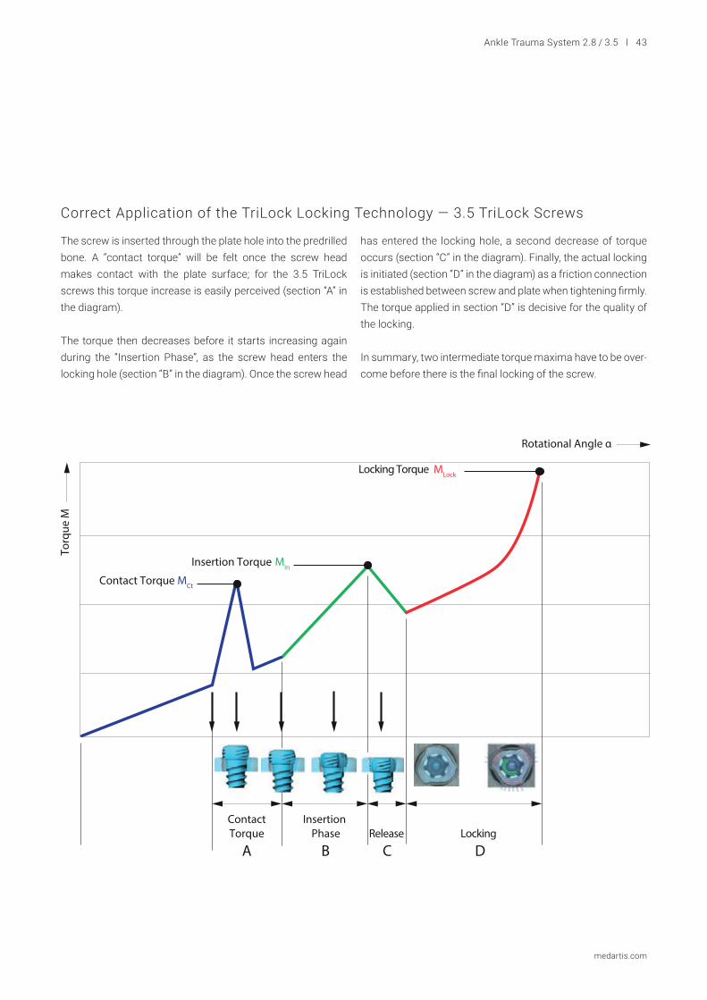
Correct Application of the TriLock Locking Technology — 3.5 TriLock Screws
The screw is inserted through the plate hole into the predrilled bone. A “contact torque” will be felt once the screw head makes contact with the plate surface; for the 3.5 TriLock screws this torque increase is easily perceived (section “A” in the diagram).
The torque then decreases before it starts increasing again during the “Insertion Phase”, as the screw head enters the locking hole (section “B” in the diagram). Once the screw head
has entered the locking hole, a second decrease of torque occurs (section “C” in the diagram). Finally, the actual locking is initiated (section “D” in the diagram) as a friction connection is established between screw and plate when tightening firmly. The torque applied in section “D” is decisive for the quality of the locking.
In summary, two intermediate torque maxima have to be over-come before there is the final locking of the screw.
44 l Ankle Trauma System 2.8 / 3.5
medartis.com
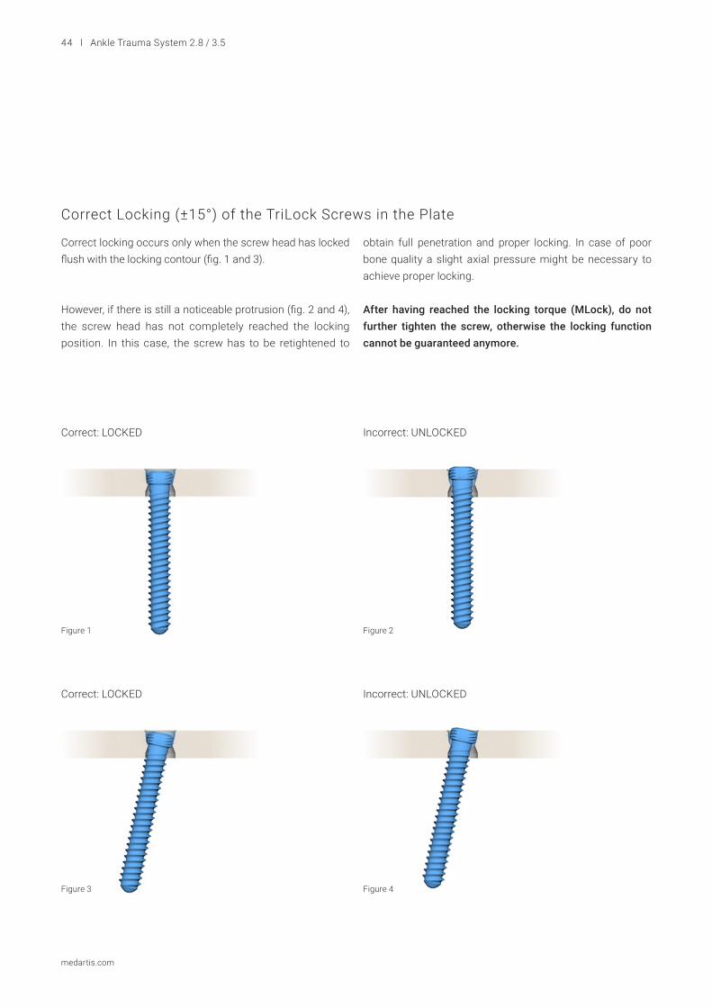
Correct Locking (±15°) of the TriLock Screws in the Plate
Correct locking occurs only when the screw head has locked flush with the locking contour (fig. 1 and 3).
However, if there is still a noticeable protrusion (fig. 2 and 4), the screw head has not completely reached the locking position. In this case, the screw has to be retightened to
obtain full penetration and proper locking. In case of poor bone quality a slight axial pressure might be necessary to achieve proper locking.
After having reached the locking torque (MLock), do not further tighten the screw, otherwise the locking function cannot be guaranteed anymore.
Correct: LOCKED
Correct: LOCKED
Incorrect: UNLOCKED
Incorrect: UNLOCKED
Figure 1
Figure 3
Figure 2
Figure 4
Ankle Trauma System 2.8 / 3.5 l 45
medartis.com
Implants, Instruments and Containers
Length Art. No. STERILE Pieces / Pkg Art. No. Pieces / Pkg
8 mm A-5800.08/1 A-5800.08/1S 1 A-5800.08 510 mm A-5800.10/1 A-5800.10/1S 1 A-5800.10 512 mm A-5800.12/1 A-5800.12/1S 1 A-5800.12 514 mm A-5800.14/1 A-5800.14/1S 1 A-5800.14 516 mm A-5800.16/1 A-5800.16/1S 1 A-5800.16 518 mm A-5800.18/1 A-5800.18/1S 1 A-5800.18 520 mm A-5800.20/1 A-5800.20/1S 1 A-5800.20 522 mm A-5800.22/1 A-5800.22/1S 1 A-5800.22 524 mm A-5800.24/1 A-5800.24/1S 1 A-5800.24 526 mm A-5800.26/1 A-5800.26/1S 1 A-5800.26 528 mm A-5800.28/1 A-5800.28/1S 1 A-5800.28 530 mm A-5800.30/1 A-5800.30/1S 1 A-5800.30 532 mm A-5800.32/1 A-5800.32/1S 1 A-5800.32 534 mm A-5800.34/1 A-5800.34/1S 1 A-5800.34 536 mm A-5800.36/1 A-5800.36/1S 1 A-5800.36 538 mm A-5800.38/1 A-5800.38/1S 1 A-5800.38 540 mm A-5800.40/1 A-5800.40/1S 1 A-5800.40 545 mm A-5800.45/1 A-5800.45/1S 1 A-5800.45 550 mm A-5800.50/1 A-5800.50/1S 1 A-5800.50 555 mm A-5800.55/1 A-5800.55/1S 1 A-5800.55 560 mm A-5800.60/1 A-5800.60/1S 1 A-5800.60 5
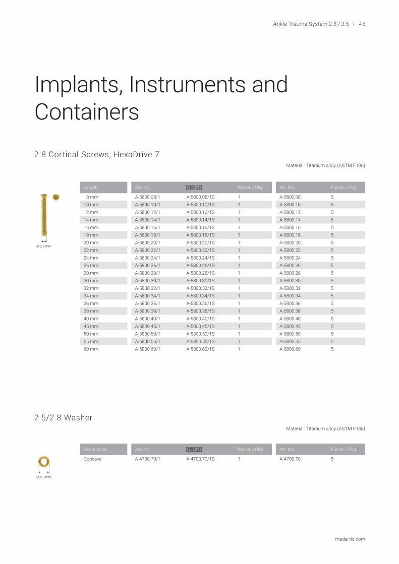
2.8 Cortical Screws, HexaDrive 7 Material: Titanium alloy (ASTM F136)
A 2.8 mm
2.5/2.8 Washer Material: Titanium alloy (ASTM F136)
A 6.0 mm
Description Art. No. STERILE Pieces / Pkg Art. No. Pieces / Pkg
Concave A-4700.70/1 A-4700.70/1S 1 A-4700.70 5

46 l Ankle Trauma System 2.8 / 3.5
medartis.com
2.8 TriLock Screws, HexaDrive 7 Material: Titanium alloy (ASTM F136)
3.5 Cortical Screws, HexaDrive 15 Material: Titanium alloy (ASTM F136)
Length Art. No. STERILE Pieces / Pkg Art. No. Pieces / Pkg
8 mm A-5850.08/1 A-5850.08/1S 1 A-5850.08 510 mm A-5850.10/1 A-5850.10/1S 1 A-5850.10 512 mm A-5850.12/1 A-5850.12/1S 1 A-5850.12 514 mm A-5850.14/1 A-5850.14/1S 1 A-5850.14 516 mm A-5850.16/1 A-5850.16/1S 1 A-5850.16 518 mm A-5850.18/1 A-5850.18/1S 1 A-5850.18 520 mm A-5850.20/1 A-5850.20/1S 1 A-5850.20 522 mm A-5850.22/1 A-5850.22/1S 1 A-5850.22 524 mm A-5850.24/1 A-5850.24/1S 1 A-5850.24 526 mm A-5850.26/1 A-5850.26/1S 1 A-5850.26 528 mm A-5850.28/1 A-5850.28/1S 1 A-5850.28 530 mm A-5850.30/1 A-5850.30/1S 1 A-5850.30 532 mm A-5850.32/1 A-5850.32/1S 1 A-5850.32 534 mm A-5850.34/1 A-5850.34/1S 1 A-5850.34 536 mm A-5850.36/1 A-5850.36/1S 1 A-5850.36 538 mm A-5850.38/1 A-5850.38/1S 1 A-5850.38 540 mm A-5850.40/1 A-5850.40/1S 1 A-5850.40 545 mm A-5850.45/1 A-5850.45/1S 1 A-5850.45 550 mm A-5850.50/1 A-5850.50/1S 1 A-5850.50 555 mm A-5850.55/1 A-5850.55/1S 1 A-5850.55 560 mm A-5850.60/1 A-5850.60/1S 1 A-5850.60 5
A 2.8 mm
Length Art. No. STERILE Pieces / Pkg
10 mm A-5901.10/1 A-5901.10/1S 112 mm A-5901.12/1 A-5901.12/1S 114 mm A-5901.14/1 A-5901.14/1S 116 mm A-5901.16/1 A-5901.16/1S 118 mm A-5901.18/1 A-5901.18/1S 120 mm A-5901.20/1 A-5901.20/1S 122 mm A-5901.22/1 A-5901.22/1S 124 mm A-5901.24/1 A-5901.24/1S 126 mm A-5901.26/1 A-5901.26/1S 128 mm A-5901.28/1 A-5901.28/1S 130 mm A-5901.30/1 A-5901.30/1S 132 mm A-5901.32/1 A-5901.32/1S 134 mm A-5901.34/1 A-5901.34/1S 136 mm A-5901.36/1 A-5901.36/1S 138 mm A-5901.38/1 A-5901.38/1S 140 mm A-5901.40/1 A-5901.40/1S 145 mm A-5901.45/1 A-5901.45/1S 150 mm A-5901.50/1 A-5901.50/1S 155 mm A-5901.55/1 A-5901.55/1S 160 mm A-5901.60/1 A-5901.60/1S 1
A 3.5 mm
Ankle Trauma System 2.8 / 3.5 l 47
medartis.com
3.5 Washer Material: Titanium alloy (ASTM F136)
3.5 TriLock Screws, HexaDrive 15 Material: Titanium alloy (ASTM F136)
A 9.0 mm
Description Art. No. STERILE Pieces / Pkg Art. No. Pieces / Pkg
Concave A-4900.70/1 A-4900.70/1S 1 A-4900.70 5
Length Art. No. STERILE Pieces / Pkg
10 mm A-5950.10/1 A-5950.10/1S 112 mm A-5950.12/1 A-5950.12/1S 114 mm A-5950.14/1 A-5950.14/1S 116 mm A-5950.16/1 A-5950.16/1S 118 mm A-5950.18/1 A-5950.18/1S 120 mm A-5950.20/1 A-5950.20/1S 122 mm A-5950.22/1 A-5950.22/1S 124 mm A-5950.24/1 A-5950.24/1S 126 mm A-5950.26/1 A-5950.26/1S 128 mm A-5950.28/1 A-5950.28/1S 130 mm A-5950.30/1 A-5950.30/1S 132 mm A-5950.32/1 A-5950.32/1S 134 mm A-5950.34/1 A-5950.34/1S 136 mm A-5950.36/1 A-5950.36/1S 138 mm A-5950.38/1 A-5950.38/1S 140 mm A-5950.40/1 A-5950.40/1S 145 mm A-5950.45/1 A-5950.45/1S 150 mm A-5950.50/1 A-5950.50/1S 155 mm A-5950.55/1 A-5950.55/1S 160 mm A-5950.60/1 A-5950.60/1S 1
A 3.5 mm
48 l Ankle Trauma System 2.8 / 3.5
medartis.com Scale 1:1
Art. No. STERILE Description Holes Holes in Shaft Pieces / Pkg
A-4954.00 A-4954.00S right 13 5 1A-4954.01 A-4954.01S left 13 5 1A-4954.02 A-4954.02S right 15 7 1A-4954.03 A-4954.03S left 15 7 1A-4954.04 A-4954.04S right 17 9 1A-4954.05 A-4954.05S left 17 9 1
A-4954.01 A-4954.00
93 m
m
14 mm
A-4954.03 A-4954.02
120
mm
14 mm
A-4954.05 A-4954.04
144
mm
14 mm
2.8/3.5 TriLock Distal Fibula Plates, Lateral Material: Titanium alloy (ASTM F136) Plate thickness: 2.5 mm
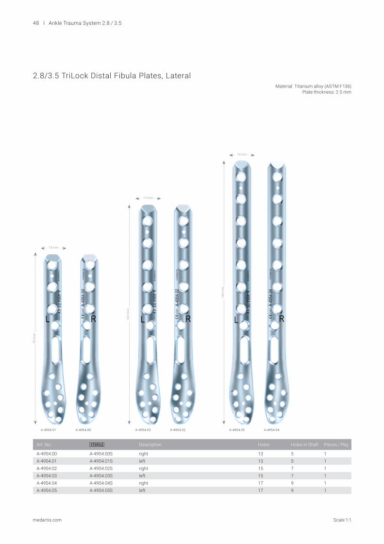
Ankle Trauma System 2.8 / 3.5 l 49
medartis.comScale 1:1
2.8/3.5 TriLock Distal Fibula Plates, Lateral Material: Titanium alloy (ASTM F136) Plate thickness: 2.5 mm
Art. No. Description Holes Holes in Shaft Pieces / PkgA-4954.06S STERILE left 19 11 1A-4954.07S STERILE right 19 11 1A-4954.08S STERILE left 21 13 1A-4954.09S STERILE right 21 13 1
168
mm
192
mm
14 mm
14 mm
A-4954.07S A-4954.09S A-4954.06S A-4954.08S
50 l Ankle Trauma System 2.8 / 3.5
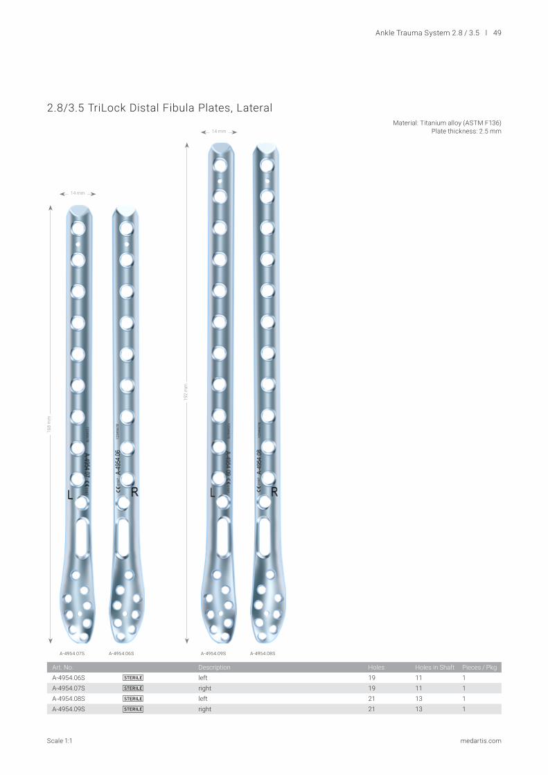
medartis.com Scale 1:1
2.8/3.5 TriLock Distal Fibula Plates, Lateral with Flap Material: Titanium alloy (ASTM F136) Plate thickness: 2.5 mm
Art. No. STERILE Description Holes Holes in Shaft Pieces / Pkg
A-4954.51 A-4954.51S left 14 5 1A-4954.52 A-4954.52S right 14 5 1A-4954.53 A-4954.53S left 16 7 1A-4954.54 A-4954.54S right 16 7 1
A-4954.51 A-4954.52 A-4954.53 A-4954.54
93 m
m
120
mm
23 mm
23 mm

Ankle Trauma System 2.8 / 3.5 l 51
medartis.comScale 1:1
Art. No. STERILE Template Holes Pieces / Pkg
A-4854.00 A-4854.00S A-4854.00TP 9 (3/6) 1A-4854.01 A-4854.01S A-4854.01TP 11 (3/8) 1A-4854.02 A-4854.02S A-4854.02TP 13 (3/10) 1A-4854.03 A-4854.03S A-4854.03TP 15 (3/12) 1A-4854.04 A-4854.04S A-4854.04TP 17 (3/14) 1
A-4854.01 A-4854.02 A-4854.03 A-4854.04
63 m
m
77 m
m
91 m
m
105
mm
119
mm
17 mm
17 mm
17 mm
17 mm
17 mm
A-4854.00
2.8 TriLock Distal Fibula Plates Material: Titanium (ASTM F67) Plate thickness: 1.6 mm
52 l Ankle Trauma System 2.8 / 3.5
medartis.com Scale 1:1
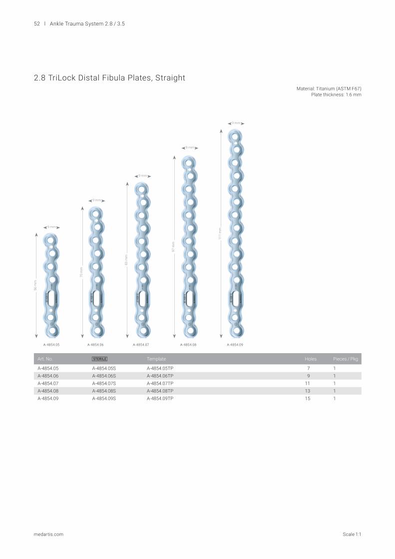
2.8 TriLock Distal Fibula Plates, Straight Material: Titanium (ASTM F67) Plate thickness: 1.6 mm
Art. No. STERILE Template Holes Pieces / Pkg
A-4854.05 A-4854.05S A-4854.05TP 7 1A-4854.06 A-4854.06S A-4854.06TP 9 1A-4854.07 A-4854.07S A-4854.07TP 11 1A-4854.08 A-4854.08S A-4854.08TP 13 1A-4854.09 A-4854.09S A-4854.09TP 15 1
9 mm
56 m
m
A-4854.05
9 mm
A-4854.06
70 m
m
9 mm
A-4854.07
83 m
m
9 mm
A-4854.08
97 m
m
9 mm
A-4854.09
111
mm

Ankle Trauma System 2.8 / 3.5 l 53
medartis.comScale 1:1
2.8/3.5 TriLock Distal Tibia Plates, Medial Material: Titanium alloy (ASTM F136) Plate thickness: 3.3 mm
Art. No. STERILE Description Holes Holes in Shaft Pieces / Pkg
A-4954.11 A-4954.11S left 11 4 1A-4954.12 A-4954.12S right 11 4 1A-4954.13 A-4954.13S left 13 6 1A-4954.14 A-4954.14S right 13 6 1A-4954.15 A-4954.15S left 15 8 1A-4954.16 A-4954.16S right 15 8 1A-4954.17 A-4954.17S left 17 10 1A-4954.18 A-4954.18S right 17 10 1
88 m
m
112
mm
136
mm
A-4954.11 A-4954.12 A-4954.13 A-4954.14 A-4954.15 A-4954.16 A-4954.17 A-4954.18
20 mm
20 mm
20 mm
160
mm
20 mm
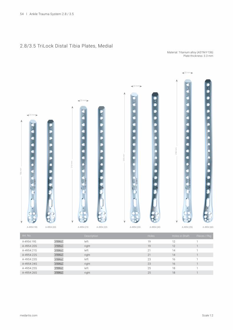
54 l Ankle Trauma System 2.8 / 3.5
medartis.com Scale 1:2
Art. No. Description Holes Holes in Shaft Pieces / Pkg
A-4954.19S STERILE left 19 12 1A-4954.20S STERILE right 19 12 1A-4954.21S STERILE left 21 14 1A-4954.22S STERILE right 21 14 1A-4954.23S STERILE left 23 16 1A-4954.24S STERILE right 23 16 1A-4954.25S STERILE left 25 18 1A-4954.26S STERILE right 25 18 1
186
mm
A-4954.19S A-4954.20S
20 mm
210
mm
A-4954.21S A-4954.22S
20 mm
235
mm
A-4954.23S A-4954.24S
20 mm
A-4954.25S A-4954.26S
258
mm
20 mm
2.8/3.5 TriLock Distal Tibia Plates, Medial Material: Titanium alloy (ASTM F136) Plate thickness: 3.3 mm
Ankle Trauma System 2.8 / 3.5 l 55
medartis.comScale 1:1
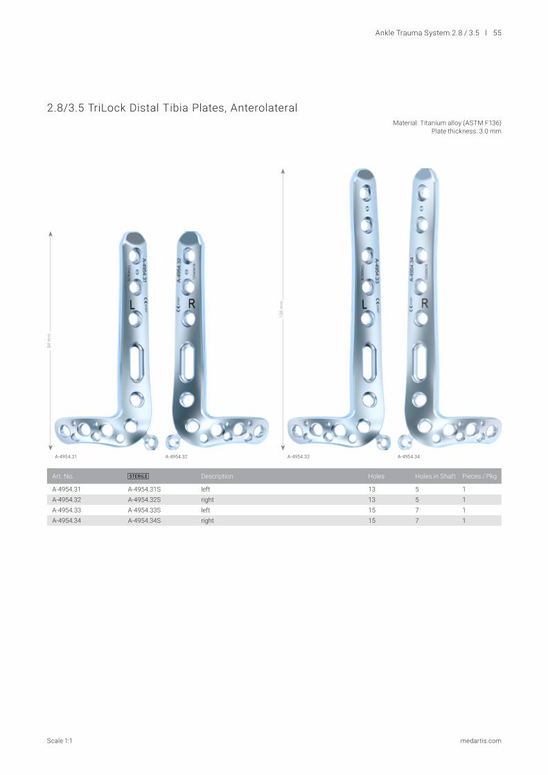
Art. No. STERILE Description Holes Holes in Shaft Pieces / Pkg
A-4954.31 A-4954.31S left 13 5 1A-4954.32 A-4954.32S right 13 5 1A-4954.33 A-4954.33S left 15 7 1A-4954.34 A-4954.34S right 15 7 1
A-4954.31 A-4954.33A-4954.32 A-4954.34
84 m
m
108
mm
2.8/3.5 TriLock Distal Tibia Plates, Anterolateral Material: Titanium alloy (ASTM F136) Plate thickness: 3.0 mm
56 l Ankle Trauma System 2.8 / 3.5
medartis.com Scale 1:2
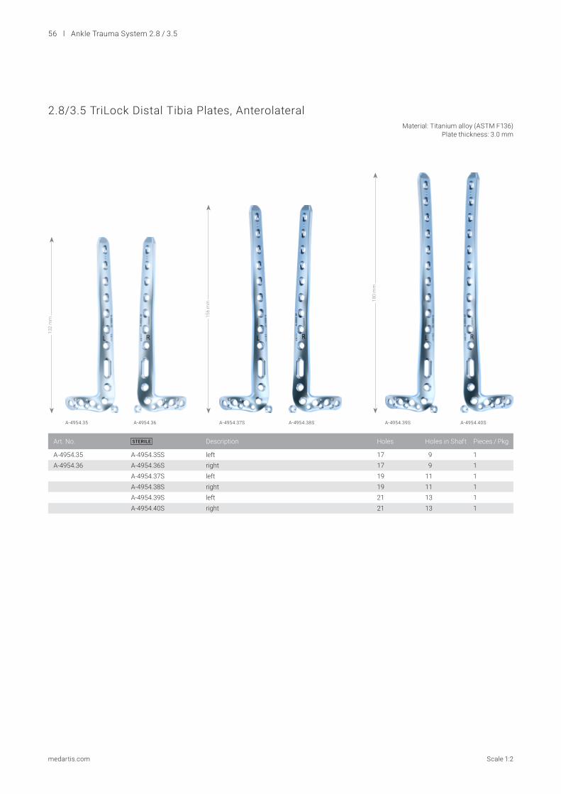
Art. No. STERILE Description Holes Holes in Shaft Pieces / Pkg
A-4954.35 A-4954.35S left 17 9 1A-4954.36 A-4954.36S right 17 9 1
A-4954.37S left 19 11 1A-4954.38S right 19 11 1A-4954.39S left 21 13 1A-4954.40S right 21 13 1
A-4954.35 A-4954.37S A-4954.39SA-4954.36 A-4954.38S A-4954.40S
132
mm 15
6 m
m 180
mm
2.8/3.5 TriLock Distal Tibia Plates, Anterolateral Material: Titanium alloy (ASTM F136) Plate thickness: 3.0 mm
Ankle Trauma System 2.8 / 3.5 l 57
medartis.comScale 1:1
Art. No. STERILE Template Description Holes Pieces / Pkg
A-4954.101 A-4954.101S A-4954.101TP T 6 (3/3) 1A-4954.102 A-4954.102S A-4954.102TP L right 6 (3/3) 1A-4954.103 A-4954.103S A-4954.103TP L left 6 (3/3) 1
A-4954.101 A-4954.103 A-4954.102
50 m
m
50 m
m
50 m
m
26 mm 26 mm 26 mm
3.5 TriLock Distal Tibia Plates Material: Titanium (ASTM F67) Plate thickness: 2.5 mm
58 l Ankle Trauma System 2.8 / 3.5
medartis.com Scale 1:1
Twist Drill A 2.35 mm
Art. No. STERILE System Size Stop Length Shaft End Pieces / Pkg
A-3832 A-3832S 2.8 50 mm 101 mm AO Quick Coupling 1
Art. No. STERILE System Size Stop Length Shaft End Pieces / Pkg
A-3934 A-3934S 3.5 70 mm 150 mm AO Quick Coupling 1
Art. No. STERILE System Size Stop Length Shaft End Pieces / Pkg
A-3834 A-3834S 2.8 10 mm 61 mm AO Quick Coupling 1
Twist Drill A 2.9 mm (for Gliding Hole)
Art. No. STERILE System Size Stop Length Shaft End Pieces / Pkg
A-3933 A-3933S 3.5 30 mm 126 mm AO Quick Coupling 1
Twist Drill A 2.6 mm
Twist Drill A 3.6 mm (for Gliding Hole)
Ankle Trauma System 2.8 / 3.5 l 59
medartis.comScale 1:1
Twist Drill A 3.0 mm
Art. No. STERILE System Size Stop Length Shaft End Pieces / Pkg
A-3931 A-3931S 3.5 70 mm 150 mm AO Quick Coupling 1
Art. No. STERILE A Description Length Pieces / Pkg
A-5040.41 1.6 mm trocar 150 mm 10A-5040.41/2S 1.6 mm trocar 150 mm 2
A-5042.41 1.6 mm lancet 150 mm 10A-5042.41/2S 1.6 mm lancet 150 mm 2
K-Wires, Stainless Steel
A-5042.41
A-5040.41
Art. No. STERILE A Thread Length Length Pieces / Pkg
A-5045.61/1 2.0 mm 10 mm 60 mm 1A-5045.61/2S 2.0 mm 10 mm 60 mm 2
A-5045.62/1 2.0 mm 15 mm 65 mm 1A-5045.62/2S 2.0 mm 15 mm 65 mm 2
A-5045.63/1 2.0 mm 20 mm 70 mm 1A-5045.63/2S 2.0 mm 20 mm 70 mm 2
A-5045.64/1 2.0 mm 25 mm 75 mm 1A-5045.64/2S 2.0 mm 25 mm 75 mm 2
Olive K-Wires, Stainless Steel
2.0 mm
A-5045.62/115 mm
A-5045.63/120 mm
A-5045.64/125 mm
A-5045.61/110 mm
60 l Ankle Trauma System 2.8 / 3.5
medartis.com Scale 1:2
Art. No. System Size Description Length Pieces / Pkg
A-2836 2.8 220 mm 1A-2931 3.5 10−70 mm 211 mm 1
Depth Gauges
A-2836
A-2931
Drill Guides
Art. No. System Size Description Length Pieces / Pkg
A-2820 2.8 for core and gliding hole 146 mm 1A-2925 3.5 cortical for twist drill A 2.6/3.6 mm 171 mm 1A-2926 3.5 compression 126 mm 1A-2927 3.5 TriLock for twist drill A 3.0 mm 126 mm 1
A-2820 A-2925
A-2926 A-2927
Art. No. System Size Description Length Pieces / Pkg
A-2826 2.5/2.8 self-holding 34 mm 1A-2921 3.5 self-holding 50 mm 1
Drill Sleeves
A-2826 A-2921
1:1 1:1
Ankle Trauma System 2.8 / 3.5 l 61
medartis.comScale 1:2
Art. No. System Size Description For Shaft End Length Pieces / Pkg
A-2073 2.8 with twist cap AO Quick Coupling 124 mm 1A-2074 3.5 AO Quick Coupling 145 mm 1A-2075 3.5 T-handle AO Quick Coupling 81 mm 1
Handles with Quick Connector
A-2073
A-2074
A-2075
Art. No. System Size Interface For Shaft End Length Pieces / Pkg
A-2013 2.5/2.8 HD7 AO Quick Coupling 75 mm 1A-2911 3.5/4.0 HD15 AO Quick Coupling 80 mm 1
Screwdriver Blades, Self-Holding
A-2013
A-2911
HD7
HD15
1:1
1:1
Plate Holding and Positioning Instrument
Art. No. System Size Length Pieces / Pkg
A-2950 2.8/3.5 178 mm 1
62 l Ankle Trauma System 2.8 / 3.5
medartis.com Scale 1:2
Plate Bending Pliers
Art. No. System Size Description Length Pieces / Pkg
A-2047 2.0−2.8 with pins 158 mm 1A-2940 3.5/4.0 158 mm 1
A-2047 A-2940
Plate Bending Iron
Art. No. System Size Length Pieces / Pkg
A-2092 2.8/3.5 192 mm 1
Ankle Trauma System 2.8 / 3.5 l 63
medartis.comScale 1:2
Reduction Forceps
Art. No. Length Pieces / Pkg
A-7014 205 mm 1A-7041 230 mm 1
A-7014
A-7041
MIPO Instrument for Tunnel Preparation
Art. No. System Size Length Pieces / Pkg
A-2051 2.8/3.5 200 mm 1
64 l Ankle Trauma System 2.8 / 3.5
medartis.com Scale 1:2
Periosteal Elevator
Hook
Art. No. Description Length Pieces / Pkg
A-7009 “Tönnis” 150 mm 1
Wound Retractor Langenbeck
Bone Elevator Hohmann
Art. No. Description Length Pieces / Pkg
A-7018 44 x 10 mm 210 mm 1
Art. No. Width Length Pieces / Pkg
A-7017 8 mm 220 mm 1
Art. No. Description Width Length Pieces / Pkg
A-7016 round edges 6 mm 190 mm 1
Ankle Trauma System 2.8 / 3.5 l 65
medartis.com
A-6608.000 (excl. implants) A-6608.001 (excl. implants) A-6608.002 (excl. implants)
Cases, Trays
A-6608.005 containing A-6608.006 (excl. screws) A-6608.010 containing A-6608-011 (excl. screws)
Art. No. Description Dimensions (W × L) Pieces / Pkg
A-6608.000 implant case APTUS ankle fibula plates 240 × 240 mm 1A-6608.001 implant case APTUS ankle medial, T and L plates 240 × 240 mm 1A-6608.002 implant case APTUS ankle anterolateral plates 240 × 240 mm 1M-6727 lid for implant and instrument case 240x240mm 240 × 240 mm 1
Art. No. Description Dimensions (W × L) Pieces / Pkg
A-6608.005 implant case APTUS ankle screws 2.8 120 × 240 mm 1A-6608.006 screw tray APTUS ankle 2.8 120 × 240 mm 1A-6608.010 implant case APTUS ankle screws 3.5 120 × 240 mm 1A-6608.011 screw tray APTUS ankle 3.5 120 × 240 mm 1M-6726 lid for implant and instrument case 120x240 mm 120 × 240 mm 1
66 l Ankle Trauma System 2.8 / 3.5
medartis.com
A-6608.015 containing A-6608.016 (excl. instruments)
A-6608.017 containing A-6608.019(excl. instruments)
A-6608.018 (excl. instruments)
A-6608.020 containing A-6608.022 (excl. instruments)
A-6608.021(excl. instruments)
Cases, Trays
Art. No. Description Dimensions (W × L) Pieces / Pkg
A-6608.015 instrument case APTUS ankle 2.8 240 × 240 mm 1A-6608.016 instrument tray APTUS ankle 2.8 240 × 240 mm 1A-6608.017 instrument case APTUS ankle 3.5 240 × 240 mm 1A-6608.018 instrument tray APTUS ankle 3.5, upper 240 × 240 mm 1A-6608.019 instrument tray APTUS ankle 3.5, lower 240 × 240 mm 1A-6608.020 instrument case APTUS ankle 240 × 240 mm 1A-6608.021 instrument tray APTUS ankle, upper 240 × 240 mm 1A-6608.022 instrument tray APTUS ankle, lower 240 × 240 mm 1M-6727 lid for implant and instrument case 240x240mm 240 × 240 mm 1
Ankle Trauma System 2.8 / 3.5 l 67
medartis.com
Storage and Transportation*
* Not available in all countries.
Articles available on request
A-5040.41/1 A-5042.41/1
Art. No. Description Dimensions (W × L × H) Pieces / Pkg
A-6610.71* storage container 265 × 257 × 238 mm 1A-6610.72* storage container 265 × 257 × 238 mm 1A-6611* lid for A-6610.xx 265 x 257 mm 1M-6710 holding rack for implant and instrument cases, for case 240 x 240 mm 252 × 243 × 143 mm 1M-6720 holding rack for implant and instrument cases, for case 240 × 240 mm 252 × 243 × 245 mm 1

Disclaimer: This information is intended to demonstrate the Medartis portfolio of medical devices. A surgeon must always rely on her or his own professional clinical judgement when deciding whether to use a particular product when treating a particular patient. Medartis is not giving any medical advice. The devices may not be available in all countries due to registration and/or medical practices. For further questions, please contact your Medartis representative (www.medartis.com). This information contains CE-marked products.For US only: Federal law restricts this device to sale by or on the order of a physician.
FOOT-01030001_v4 / © 2021-04, Medartis AG, Switzerland. All technical data subject to alteration.
MANUFACTURER & HEADQUARTERS
Medartis AG | Hochbergerstrasse 60E | 4057 Basel / Switzerland
P +41 61 633 34 34 | F +41 61 633 34 00 | www.medartis.com
SUBSIDIARIES
Australia | Austria | Brazil | China | France | Germany | Japan | Mexico | New Zealand | Poland | Spain
UK | USA
For detailed information regarding our subsidiaries and distributors, please visit www.medartis.com