Surgical Robotics Springer - UCLA
41
Jacob Rosen l Blake Hannaford Richard M. Satava Editors Surgical Robotics Systems Applications and Visions
Transcript of Surgical Robotics Springer - UCLA
Jacob Rosen l Blake HannafordRichard M. SatavaEditors
Surgical Robotics
Systems Applications and Visions
EditorsJacob RosenDepartment of Computer EngineeringJack Baskin School of EngineeringUniversity of California Santa Cruz1156 High Street, Santa CruzCA 95064, [email protected]
Blake HannafordDepartment of Electrical EngineeringUniversity of WashingtonBox 325500, SeattleWashington [email protected]
Richard M. SatavaDepartment of SurgeryUniversity of Washington Medical CenterBox 3564101959 Pacific Street NE, SeattleWashington 98195, [email protected]
ISBN 978-1-4419-1125-4 e-ISBN 978-1-4419-1126-1DOI 10.1007/978-1-4419-1126-1Springer New York Dordrecht Heidelberg London
# Springer Science+Business Media, LLC 2011All rights reserved. This work may not be translated or copied in whole or in part without the writtenpermission of the publisher (Springer Science+Business Media, LLC, 233 Spring Street, New York,NY 10013, USA), except for brief excerpts in connection with reviews or scholarly analysis. Use inconnection with any form of information storage and retrieval, electronic adaptation, computer software,or by similar or dissimilar methodology now known or hereafter developed is forbidden.The use in this publication of trade names, trademarks, service marks, and similar terms, even if they arenot identified as such, is not to be taken as an expression of opinion as to whether or not they are subjectto proprietary rights.
Printed on acid-free paper
Springer is part of Springer ScienceþBusiness Media (www.springer.com)

Chapter 8
Raven: Developing a Surgical Robot
from a Concept to a Transatlantic
Teleoperation Experiment
Jacob Rosen, Mitchell Lum, Mika Sinanan, and Blake Hannaford
8.1 Introduction
For decades surgery and robotics were progressing along two parallel paths.
In surgery, minimally invasivesurgery (MIS) revolutionized the way a significant
number of surgical interventions were performed. Minimally invasive surgery
allows the surgeon to make a few small incisions in the patient, rather than making
one large incision for access. This technique allows for significantly faster recovery
times, less trauma, and decreased pain medication requirements for the patient.
In robotics, teleoperation integrated the human into robotic systems. Only in the
last decade have surgery and robotics reached a level of maturity that allowed safe
assimilation between the two in a teleoperation mode for creating a new kind of
operating room with the potential for surgical innovation long into the future [1].
A detailed historical overview of surgical robotics is beyond the scope of this
chapter. The reader may refer to several published papers, which collectively may
provide a comprehensive survey of the field of surgical robotics and its applications
in various sub-disciplines of surgery and medicine [2–17]. The remaining of this
section will provide a brief overview of key systems and millstones of the research
activities in the field of surgical robotics and telesurgery.
One of the earliest applications of robotics in surgery in mid 1980s included a
modified Puma 560 which was used as a positioning device to orient a needle for
biopsy of the brain on a 52 year-oldmale [18]. In parallel research efforts at IBMwere
focused on a bone cutting robot with clinical application in total hip-replacement – a
system later know as the ROBODOC [19]. The late 1980s also brought on a revolution
in surgical intervention. Jacques Perrisat, MD, from Bordeaux, France presented a
J. Rosen (*)
Department of Computer Engineering, Jack Baskin School of Engineering,
University of California Santa Cruz, 1156 High Street, Santa Cruz, CA 95064, USA
e-mail: [email protected]
# 2006 IEEE. Mitchell J.H. Lum, Jacob Rosen, M.N. Sinanan, Blake Hannaford, Optimization of
Spherical Mechanism for a Minimally Invasive Surgical Robot: Theoretical And Experimental
Approaches”, IEEE Transactions on Biomedical Engineering Vol. 53, No. 7, pp. 1440–1445,
July 2006
J. Rosen et al. (eds.), Surgical Robotics: Systems Applications and Visions,DOI 10.1007/978-1-4419-1126-1_8, # Springer Science+Business Media, LLC 2011
159

video clip at SAGES (Society of American Gastrointestinal Endoscopic Surgeons) of
the first laparoscopic cholecystectomy (gall bladder removal). Minimally invasive
surgery techniques greatly influenced the approaches that roboticists have taken
toward robot assisted interventions. These key events set the stage for an introduction
of surgical robotics into a clinical setup.
Two ground braking systems were developed in academia in the mid to late 1990s
both using a four bar mechanism: the Silver and the Black Falcon [20] and the
Laparoscopic Telesurgery Workstation [21]. Intuitive Surgical Inc. and Computer
Motion Inc. both produced commercially available FDA-approved surgical robot
systems for MIS. Computer Motion’s Zeus surgical robot held a surgical tool on a
SCARA-type manipulator. The Intuitive Surgical Inc. da Vinci R uses a an extended
parallel 4-bar mechanism. The deVinci synthesized two sub systems: (1) The surgeon
console (master) including a 3D vision was originally developed by SRI as part of a
system known as the M7 – A surgical robot for open surgery; (2) the surgical robot
itself along with the wristed tools were based on the Black Falcon developed byMIT.
In 2003, after years of litigation and counter-litigation over intellectual property
rights, the two companies merged under the name Intuitive Surgical Inc. (ISI).
There are currently several hundreds da Vinci systems in use throughout the world.
Telesurgery on a human patient was accomplished on September 9, 2001 by
Marescaux and Gagner. In collaboration with Computer Motion, they used a
modified Zeus system to teleoperate between New York City and Strasbourg,
France under a 155 ms time delay using a dedicated Asynchronous Transfer
Mode (ATM) communication link [22, 23]. Several key non-clinical teleoperation
experiments were conducted with both the RAVEN, and the M7 in extreme
environment (desert, underwater, and zero gravity) demonstrated the capabilities
of surgical robotic systems to deliver surgical expertise along large distance with a
combination of wired and wireless communication [24–27].
In Asia, a group from the University of Tokyo has recently been working on a
new telesurgery system [19, 28], and has completed laparoscopic cholcystectomy
on a porcine model between sites in Japan, and more recently between Japan and
Thailand [1, 2]. In Europe, the Laboratoire de Robotique de Paris at University of
Paris, (LRP) uses a spherical mechanism similar to the RAVEN. This robot moves
the port in addition to the tool. This allows to embed force sensors in the device that
give a direct reading of the forces at the tool tip, instead of the combined interaction
forces of the tool/tissue and trocar/abdomen.
The Light Endoscopic Robot (LER) was developed at the University of Hawaii,
Manoa. This device was designed to guide an endoscopic camera, but is now
capable of holding disposable endoscopic graspers as well as a tool with wrist
articulation [29, 30].
The following chapter describes the research efforts lasted for more the a decade
in developing a fully operational surgical robot – the RAVEN, based on a profound
collaboration between surgeons and engineers. It will cover: (1) the surgical specifi-
cation of the system that was based on quantitative measurements in an animal lab as
well as the operating room (2) the mechanism kinematic optimization based on these
specs; (3) the system integration efforts; and (4) the experimental results of system
performance in multiple field and lab experiments of teleoperation under time delay.
160 J. Rosen et al.
8.2 Design of the Surgical Robot
8.2.1 Clinical Requirements
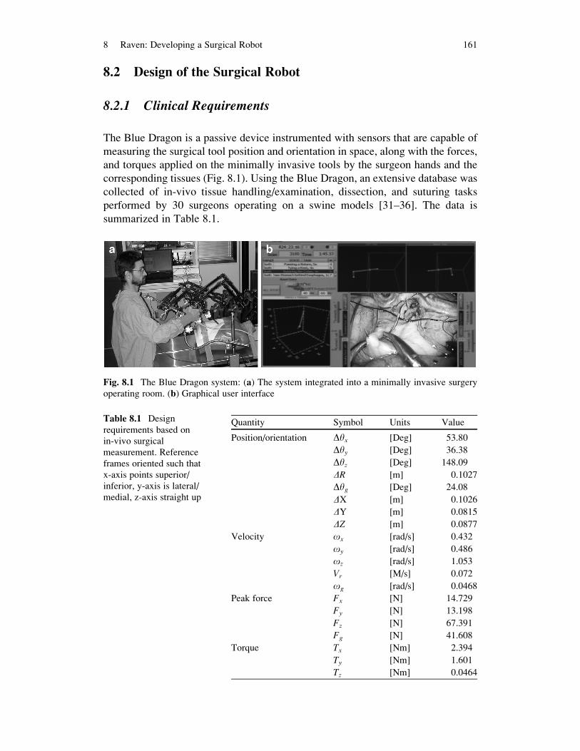
The Blue Dragon is a passive device instrumented with sensors that are capable of
measuring the surgical tool position and orientation in space, along with the forces,
and torques applied on the minimally invasive tools by the surgeon hands and the
corresponding tissues (Fig. 8.1). Using the Blue Dragon, an extensive database was
collected of in-vivo tissue handling/examination, dissection, and suturing tasks
performed by 30 surgeons operating on a swine models [31–36]. The data is
summarized in Table 8.1.
Fig. 8.1 The Blue Dragon system: (a) The system integrated into a minimally invasive surgery
operating room. (b) Graphical user interface
Table 8.1 Design
requirements based on
in-vivo surgical
measurement. Reference
frames oriented such that
x-axis points superior/
inferior, y-axis is lateral/
medial, z-axis straight up
Quantity Symbol Units Value
Position/orientation Dyx [Deg] 53.80
Dyy [Deg] 36.38
Dyz [Deg] 148.09
DR [m] 0.1027
Dyg [Deg] 24.08
DX [m] 0.1026
DY [m] 0.0815
DZ [m] 0.0877
Velocity ox [rad/s] 0.432
oy [rad/s] 0.486
oz [rad/s] 1.053
Vr [M/s] 0.072
og [rad/s] 0.0468
Peak force Fx [N] 14.729
Fy [N] 13.198
Fz [N] 67.391
Fg [N] 41.608
Torque Tx [Nm] 2.394
Ty [Nm] 1.601
Tz [Nm] 0.0464
8 Raven: Developing a Surgical Robot 161

Analysis of this data indicated that, 95% of the time, the surgical tools were located
within a conical range of motion with a vertex angle of 60 (termed the dexterous
workspace, DWS). A measurement taken on a human patient showed that, in order to
reach the full extent of the abdomen, the tool needed to move 90� in the mediolateral
(left to right) and 60� in the superior/inferior direction (head to foot) – Fig. 8.2a. Theextended dexterous workspace (EDWS)was defined as a conical range ofmotionwith
a vertex angle of 90and is the workspace required to reach the full extent of the human
abdomen without reorientation of the base of the robot – Fig. 8.2b. These parameters,
obtained through surgical measurement, served as a basis for the kinematic optimiza-
tion of the RAVEN spherical mechanism [15, 18].
8.2.2 Kinematics of a Spherical Mechanism
8.2.2.1 Description of the Mechanism and Frame Assignments
In the class of sphericalmechanisms, all links’ rotation and translation axes intersect at
a signal point or at infinity, referred to as the mechanism’s remote center of rotation.
Locating the remote center at the tool’s point of entry to the human body through the
surgical port, as typically done in minimally invasive surgery (MIS), constitutes a
point in space where the surgical tool may only rotate around it but not translated with
respect to it. The selected spherical mechanism has two configurations in the form of
parallel (5R – Fig. 8.3a) and serial (2R – Fig. 8.3b) configurations. The parallel
mechanism is composed of two serial arms: Arm 1 – Link13 and Link35 and Arm
2 – Link24 and Link46 joined by a stationary base defined by Link12 through Joints
Fig. 8.2 Workspace definitions of the surgical robot in MIS (a) dexterous workspace – High
dexterity region defined by a right circular cone with a vertex angle of 60and contains 95% of the
tool motions based on in-vivo measurements. (b) Extended Dexterous Work Space – An elliptical
cone with a vertex angle of 60–90 represents the reachable workspace such that any organ in the
abdomen can be reached by the endoscopic tool
162 J. Rosen et al.
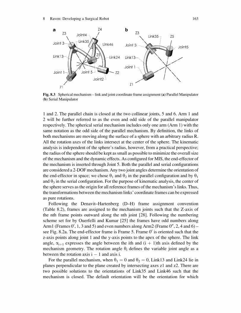
1 and 2. The parallel chain is closed at the two collinear joints, 5 and 6. Arm 1 and
2 will be further referred to as the even and odd side of the parallel manipulator
respectively. The spherical serial mechanism includes only one arm (Arm 1) with the
same notation as the odd side of the parallel mechanism. By definition, the links of
both mechanisms are moving along the surface of a sphere with an arbitrary radius R.
All the rotation axes of the links intersect at the center of the sphere. The kinematic
analysis is independent of the sphere’s radius, however, from a practical perspective;
the radius of the sphere should be kept as small as possible tominimize the overall size
of the mechanism and the dynamic effects. As configured for MIS, the end-effector of
the mechanism is inserted through Joint 5. Both the parallel and serial configurations
are considered a 2-DOFmechanism. Any two joint angles determine the orientation of
the end-effector in space; we chose y1 and y2 in the parallel configuration and by y1and y3 in the serial configuration. For the purpose of kinematic analysis, the center of
the sphere serves as the origin for all reference frames of the mechanism’s links. Thus,
the transformations between themechanism links’ coordinate frames can be expressed
as pure rotations.
Following the Denavit–Hartenberg (D–H) frame assignment convention
(Table 8.2), frames are assigned to the mechanism joints such that the Z-axis of
the nth frame points outward along the nth joint [28]. Following the numbering
scheme set for by Ouerfelli and Kumar [25] the frames have odd numbers along
Arm1 (Frames 00, 1, 3 and 5) and even numbers along Arm2 (Frame 000, 2, 4 and 6) –see Fig. 8.2a. The end-effector frame is Frame 5. Frame 00 is oriented such that the
z-axis points along joint 1 and the y-axis points to the apex of the sphere. The link
angle, aiþ1 expresses the angle between the ith and (i þ 1)th axis defined by the
mechanism geometry. The rotation angle yi defines the variable joint angle as a
between the rotation axis i � 1 and axis i.
For the parallel mechanism, when y1 ¼ 0 and y2 ¼ 0, Link13 and Link24 lie in
planes perpendicular to the plane created by intersecting axes z1 and z2. There are
two possible solutions to the orientations of Link35 and Link46 such that the
mechanism is closed. The default orientation will be the orientation for which
Fig. 8.3 Spherical mechanism – link and joint coordinate frame assignment (a) ParallelManipulator
(b) Serial Manipulator
8 Raven: Developing a Surgical Robot 163

y6 < 180�. This will be referred to as the ‘end-effector in’ orientation. For the serialmechanism, when y1¼ 0 Link13 lies in a plane perpendicular to the plane created by
intersecting axes z1 and x1. When y3 ¼ 0, Link35 is folded back onto L13.
The transformation matrices between frames (8.1) are based on the DH-parame-
ter notation that is summarized in Table 8.1. Because all the joints’ translation
parameters (ai, di) are zero, the kinematic problem is reduced to describing the
orientation of the end-effector in space. Thus, the generalized frame transformation
matrix is reduced from the typical 4 � 4 translation and rotation matrix, to a 3 � 3
rotation matrix (8.1). The short notation for trigonometric functions sin and cos as cand s will be used throughout the manuscript.
i�1i R ¼
cyi �syi 0
syi cai�1 cyi cai�1 �sai�1
syi sai�1 cyi sai�1 cai�1
264
375 (8.1)
8.2.2.2 Forward Kinematics
Given the mechanism parameters (ai�1, yi) the forward kinematics defines the
orientation of the end-effector 00u expressed in Frame 00. The following sections
describe the forward kinematics of the parallel and serial mechanisms.
Parallel Manipulator
Given the two joint angles y1 and y2, to find the end-effector orientation the full
pose of the mechanism must first be solved. A geometric or analytical approach
may be utilized in order to solve for parallel mechanism joint angles y3, y4 and y5.The first step in the geometric solution is posing Link13 and Link24 based on joint
rotation angles y1 and y2. The second step is to sweep links Link35 andLink46 throughtheir range of motion by varying the joint angles y3 and y4. A closed chain parallel
manipulator is formed at the intersection of the two paths swept by joints 5 and 6.
The analytical approach was used, which involves taking a closed-loop coordi-
nate transformation around the 5R parallel manipulator, starting and ending at the
same frame (Frame 1). The rotation matrix around a closed chain is equal to an
identity matrix I formed as a series of transformation matrices. Using the rotation
matrices i�1i R around the closed chain and the specified joint angles y1 and y2 (8.2)
sets up a system of three equations and three unknown joint angles, y3, y4 and y6.
I ¼ 11R ¼ 1
3R35R
56R
64R
42R
20R
0000R
0001 R (8.2)
164 J. Rosen et al.

The resultant matrix equation is given in terms of sinyi and cosyi (i ¼ 3, 4, 6) In
order to solve for the two solutions of this system the following trigonometric
relation is needed
syi ¼ �ffiffiffiffiffiffiffiffiffiffiffiffiffiffiffiffi1� c2yi
p(8.3)
Once all the joints angles (y1. . .y6) are known, the end-effector orientation can be
determined by utilizing the forward kinematics expression of one serial manipulator
subset. See the following section for details.
Serial Manipulator
Given the two joint angles y1 and y3, the forward kinematics of the 2R serial
mechanism define the orientation of the end-effector. Using the rotation matrices
(i�1i R) – (1) and the joint parameters (Table 8.1), the coordinate transformation from
the base to the end-effector is expressed as
005 R ¼ 00
1 R13R
35R (8.4)
One may note that tool roll, y5, is not represented in (4). As a result, rather than
expressing the entire orientation of the end-effector frame, it is sensible to express a
vector that is collinear with the end-effector axis, Z5. This vector is expressed in
Frame 5 as 5uz ¼ ½0 0 1�T . The end-effector axis, Z5 vector in Frame 00 (00u) is given
by (5) using (4). The vector 00u has its origin at the center of the sphere, and it points
along the mechanism’s end-effector, representing the orientation of the tool
attached to the end-effector.
00u ¼00ux00uy00uz
24
35 ¼ 00
5 R0
0
1
24
35 ¼
cy1sy3sa35 þ sy1cy3ca13 � sy1sa13ca35sy1sy3sa35 � cy1cy3ca13 � cy1sa13ca35
cy3sa13sa35 þ ca13ca35
24
35 (8.5)
8.2.2.3 Inverse Kinematics
Given the mechanism parameters (ai�1) and the end-effector orientation 00uexpressed in Frame 00 the inverse kinematics defines the mechanism joint angles
(yi). Multiple solutions are available for any 00u in the workspace for both parallel
and serial mechanism configurations. However, due to practical considerations of
the physical joint limits, all the solutions are eliminated except one.
8 Raven: Developing a Surgical Robot 165
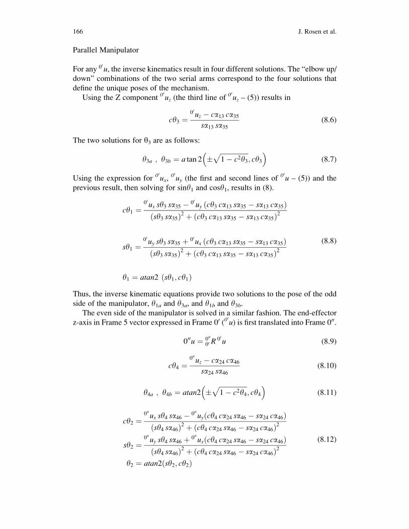
Parallel Manipulator
For any 00u, the inverse kinematics result in four different solutions. The “elbow up/
down” combinations of the two serial arms correspond to the four solutions that
define the unique poses of the mechanism.
Using the Z component 00uz (the third line of 00uz – (5)) results in
cy3 ¼00uz � ca13 ca35
sa13 sa35(8.6)
The two solutions for y3 are as follows:
y3a ; y3b ¼ a tan 2 �ffiffiffiffiffiffiffiffiffiffiffiffiffiffiffiffiffi1� c2y3
p; cy3
� �(8.7)
Using the expression for 00ux,00uy (the first and second lines of 00u – (5)) and the
previous result, then solving for siny1 and cosy1, results in (8).
cy1 ¼00ux sy3 sa35 � 00uy ðcy3 ca13 sa35 � sa13 ca35Þðsy3 sa35Þ2 þ ðcy3 ca13 sa35 � sa13 ca35Þ2
sy1 ¼00uy sy3 sa35 þ 00ux ðcy3 ca13 sa35 � sa13 ca35Þðsy3 sa35Þ2 þ ðcy3 ca13 sa35 � sa13 ca35Þ2
y1 ¼ atan2 ðsy1; cy1Þ
(8.8)
Thus, the inverse kinematic equations provide two solutions to the pose of the odd
side of the manipulator, y1a and y3a, and y1b and y3b.The even side of the manipulator is solved in a similar fashion. The end-effector
z-axis in Frame 5 vector expressed in Frame 00 (00u) is first translated into Frame 000.
000u ¼ 00000 R
00u (8.9)
cy4 ¼000uz � ca24 ca46
sa24 sa46(8.10)
y4a ; y4b ¼ atan2 �ffiffiffiffiffiffiffiffiffiffiffiffiffiffiffiffiffi1� c2y4
p; cy4
� �(8.11)
cy2 ¼000ux sy4 sa46 � 000uyðcy4 ca24 sa46 � sa24 ca46Þðsy4 sa46Þ2 þ ðcy4 ca24 sa46 � sa24 ca46Þ2
sy2 ¼000uy sy4 sa46 þ 000uxðcy4 ca24 sa46 � sa24 ca46Þðsy4 sa46Þ2 þ ðcy4 ca24 sa46 � sa24 ca46Þ2
y2 ¼ atan2ðsy2; cy2Þ
(8.12)
166 J. Rosen et al.
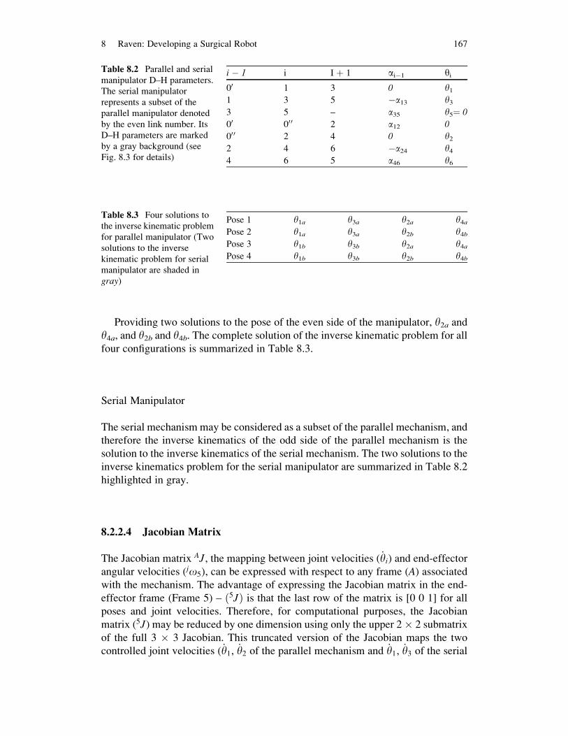
Providing two solutions to the pose of the even side of the manipulator, y2a andy4a, and y2b and y4b. The complete solution of the inverse kinematic problem for all
four configurations is summarized in Table 8.3.
Serial Manipulator
The serial mechanism may be considered as a subset of the parallel mechanism, and
therefore the inverse kinematics of the odd side of the parallel mechanism is the
solution to the inverse kinematics of the serial mechanism. The two solutions to the
inverse kinematics problem for the serial manipulator are summarized in Table 8.2
highlighted in gray.
8.2.2.4 Jacobian Matrix
The Jacobian matrix AJ, the mapping between joint velocities ( _yi) and end-effector
angular velocities (jo5), can be expressed with respect to any frame (A) associatedwith the mechanism. The advantage of expressing the Jacobian matrix in the end-
effector frame (Frame 5) – ð5JÞ is that the last row of the matrix is [0 0 1] for all
poses and joint velocities. Therefore, for computational purposes, the Jacobian
matrix (5J) may be reduced by one dimension using only the upper 2� 2 submatrix
of the full 3 � 3 Jacobian. This truncated version of the Jacobian maps the two
controlled joint velocities ( _y1, _y2 of the parallel mechanism and _y1, _y3 of the serial
Table 8.3 Four solutions to
the inverse kinematic problem
for parallel manipulator (Two
solutions to the inverse
kinematic problem for serial
manipulator are shaded in
gray)
Pose 1 y1a y3a y2a y4aPose 2 y1a y3a y2b y4bPose 3 y1b y3b y2a y4aPose 4 y1b y3b y2b y4b
Table 8.2 Parallel and serial
manipulator D–H parameters.
The serial manipulator
represents a subset of the
parallel manipulator denoted
by the even link number. Its
D–H parameters are marked
by a gray background (see
Fig. 8.3 for details)
i � 1 i I þ 1 ai�1 yi
00 1 3 0 y11 3 5 �a13 y33 5 – a35 y5¼ 0
00 00 0 2 a12 0
00 0 2 4 0 y22 4 6 �a24 y44 6 5 a46 y6
8 Raven: Developing a Surgical Robot 167
mechanism) to end-effector angular velocity. This version of the Jacobian will later
be used for calculating the manipulator isotropy.
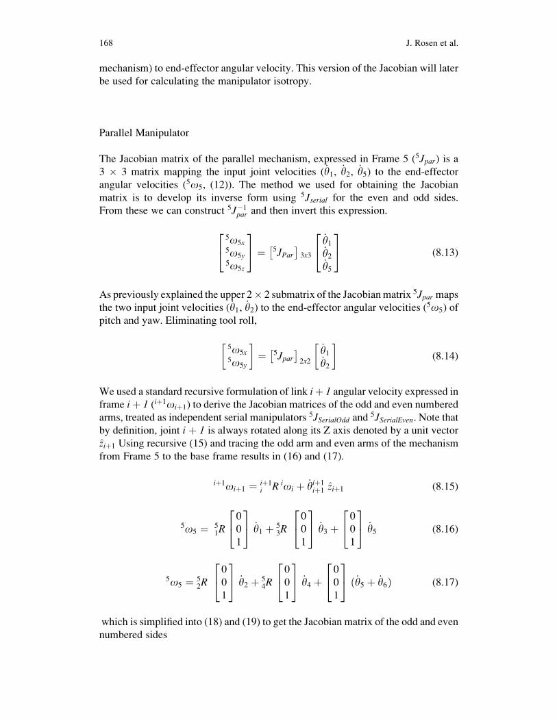
Parallel Manipulator
The Jacobian matrix of the parallel mechanism, expressed in Frame 5 (5Jpar) is a3 � 3 matrix mapping the input joint velocities ( _y1, _y2, _y5) to the end-effector
angular velocities (5o5, (12)). The method we used for obtaining the Jacobian
matrix is to develop its inverse form using 5Jserial for the even and odd sides.
From these we can construct 5J�1par and then invert this expression.
5o5x5o5y5o5z
24
35 ¼ 5JPar
� �3x3
_y1_y2_y5
24
35 (8.13)
As previously explained the upper 2� 2 submatrix of the Jacobianmatrix 5Jpar maps
the two input joint velocities ( _y1, _y2) to the end-effector angular velocities (5o5) of
pitch and yaw. Eliminating tool roll,
5o5x5o5y
� �¼ 5Jpar� �
2x2
_y1_y2
� �(8.14)
We used a standard recursive formulation of link iþ 1 angular velocity expressed inframe iþ 1 (iþ1oiþ1) to derive the Jacobian matrices of the odd and even numbered
arms, treated as independent serial manipulators 5JSerialOdd and5JSerialEven. Note that
by definition, joint i þ 1 is always rotated along its Z axis denoted by a unit vector
ziþ1 Using recursive (15) and tracing the odd arm and even arms of the mechanism
from Frame 5 to the base frame results in (16) and (17).
iþ1oiþ1 ¼ iþ1i R ioi þ _yiþ1
iþ1 ziþ1 (8.15)
5o5 ¼ 51R
0
0
1
24
35 _y1 þ 5
3R0
0
1
24
35 _y3 þ
0
0
1
24
35 _y5 (8.16)
5o5 ¼ 52R
0
0
1
24
35 _y2 þ 5
4R0
0
1
24
35 _y4 þ
0
0
1
24
35 ð _y5 þ _y6Þ (8.17)
which is simplified into (18) and (19) to get the Jacobian matrix of the odd and even
numbered sides
168 J. Rosen et al.

5o5x5o5y5o5z
24
35 ¼ 5JSerial Odd
� � _y1_y3_y5
24
35
¼ 51R� � 0
0
1
24
35 5
3R� � 0
0
1
24
35 0
0
1
24
35
24
35 _y1
_y3_y5
24
35 (8.18)
5o5x5o5y5o5z
24
35 ¼ 5JSerialEven
� � _y2_y4
_y5 þ _y6
24
35
¼ 52R� � 0
0
1
24
35 5
4R� � 0
0
1
24
35 0
0
1
24
35
24
35 _y2
_y4_y5 þ _y6
24
35 (8.19)
By inverting these equations we obtain
_y1_y3_y5
24
35 ¼ 5
1R� � 0
0
1
24
35 5
3R� � 0
0
1
24
35 0
0
1
24
35
24
35�1 5o5x
5o5y5o5z
24
35
¼ 5JSerial Odd� ��1
5o5x5o5y5o5z
24
35 (8.20)
_y2_y4
_y5 þ _y6
24
35 ¼ 5
2R� � 0
0
1
24
35 5
4R� � 0
0
1
24
35 0
0
1
24
35
24
35�1 5o5x
5o5y5o5z
24
35
¼ 5JSerial Even� ��1
5o5x5o5y5o5z
24
35 (8.21)
The first rows of (20) and (21) define y:
1and y
:
2respectively as a function of end-
effector angular velocity 5o5 and the inverted Jacobian matrices of the even and
odd arms respectively. For k ¼ 1, 2, 3, the kth column of the Jacobian
y1�¼ 5J
SerialOdd�1 ð1; kÞ
h i5o5x
5o5y5o5z
� �T (8.22)
y2�¼ 5J
SerialEven�1 ð1; kÞ
h i5o5x
5o5y5o5z
� �T (8.23)
As previously explained, the benefit of expressing the Jacobian matrix in the end-
effector Frame 5 is the following simple representation of the joint angular velocity.
8 Raven: Developing a Surgical Robot 169

y�
5¼ 0 0 1½ � 5o5x
5o5y5o5z
� �T (8.24)
Assembling individual joint velocities into matrix form allows us to formulate the
inverse Jacobian for the parallel manipulator
y�
1
y�
2
y�
5
2666664
3777775 ¼
5JSerialOdd
�1 ð1; kÞ5J
SerialEven�1 ð1; kÞ
0 0 1
24
35 5o5x
5o5y5o5z
24
35 (8.25)
The relationship between the two input joint angular velocities ( _y1and _y2) and the
angular velocity of the end-effector, considering only the pitch and yaw of the tool
(5o5x,5o5y) allows us to analyze only the upper 2 � 2 sub-matrix of the Jacobian
Inverse. For k ¼ 1, 2
y�
1
y�
2
264
375 ¼
5J�1
SerialOdd ð1; kÞ5J
�1
SerialEven ð1; kÞ
" #5o5x5o5y
� �(8.26)
Inverting this inverse Jacobiangives the Jacobianmatrix for theparallelmechanism(14).
Serial Manipulator
Using the odd numbered side of the parallel mechanism, the Jacobian matrix of the
serial mechanism can be derived from (18). Based on the previous justification, the
upper 2 � 2 submatrix of the full 3 � 3 Jacobian relates the controlled axes of
motion to the end-effector velocity:
5o5x5o5xy
� �¼ J5truncated½ �2x2
_y1_y3
� �(8.27)
8.2.3 Kinematic Optimization
Experimental results led to the definition of engineering requirements as deriva-
tives from the clinical requirements (see Sect. 8.2.1). The optimization process
was developed to define the mechanism parameters (link angles a13, a35, a24, a46,a12) so that the workspace of the mechanism covers the entire EDWS while
170 J. Rosen et al.

providing high dexterity manipulation within the DWS. The goal of a high
performance yet compact mechanism was achieved by careful selection of the
scoring criteria.
Up to this point, the analysis has been purely mathematical. The manipulator
could move through singularities, fold on itself and solve for arbitrary poses
without regard to how a physically implemented device might accomplish this.
Based on mechanical design of the serial manipulator the range of motion of the
first joint angle is 180�(0� <y1<180�) and the range of motion of the second
joint is 160� (20� <y3 <180�). By adding these joint limits into the optimization,
the true reachable workspace of a physically implemented device could be
analyzed.
8.2.3.1 Mechanism Isotropy
The Jacobian matrix allows one to analyze the kinematic performance of a mecha-
nism. One performance metric using the Jacobian matrix is Yoshiakawa’s manipu-
lability measure, specified in [20]. The manipulability measure most commonly
used ranges from 1 to infinity.
o ¼ffiffiffiffiffiffiffiffiffiffiffiffiffiffiffiffiffiffiffiffiffiffiffiffiffiffiffiffiffidet J yð ÞJT yð Þð Þ
p(8.28)
In contrast, mechanism isotropy is a scoring criterion that ranges from 0 to 1.
Isotropy is defined in (29) as the ratio between the lowest eigenvalue (lmin) and the
highest eigenvalue (lmax) of the Jacobian [37]. Note that the isotropy is a function of
the mechanism’s input joint angles (yi). For the serial mechanism, these angles are
y1; y3 and for the parallel mechanism, y1; y2
ISOðyiÞ ¼ lmin
lmax
ISO 2 h0; 1i (8.29)
Our analysis uses isotropy as the measure of performance because numerically the
range of scores was easier to deal with. Given a design candidate (serial mechanism
link angles a13 and a35 or parallel mechanism link angles a13,a35,a24,a46,a12), forevery mechanism pose there is an associated isotropy value in the range of 0–1.
An isotropy measure of 0 means the mechanism is in a singular configuration and
has lost a degree of freedom so there is a direction in which it can no longer move.
An isotropy measure of 1 means the mechanism can move equally well in all
directions.
Once the kinematic equations and a performance measure are defined, one can
evaluate the performance of a particular design candidate at each point its work-
space. The integration of the isotropy score over the DWS or EDWS is used as one
component of a scoring function for the specific design candidate.
8 Raven: Developing a Surgical Robot 171
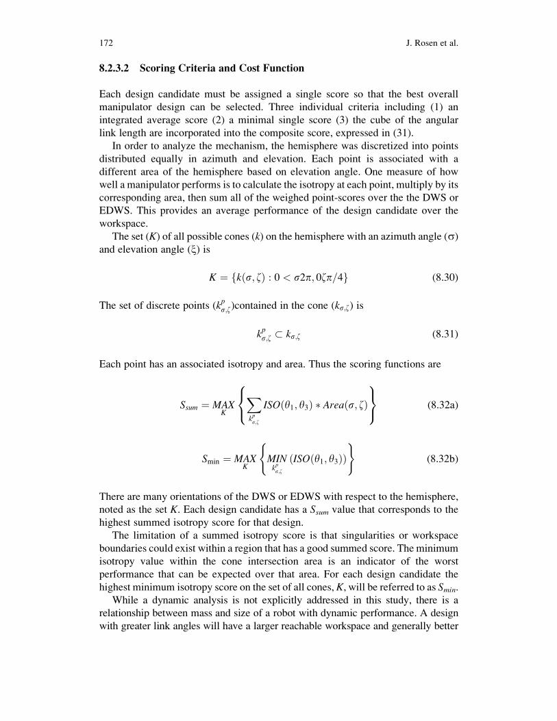
8.2.3.2 Scoring Criteria and Cost Function
Each design candidate must be assigned a single score so that the best overall
manipulator design can be selected. Three individual criteria including (1) an
integrated average score (2) a minimal single score (3) the cube of the angular
link length are incorporated into the composite score, expressed in (31).
In order to analyze the mechanism, the hemisphere was discretized into points
distributed equally in azimuth and elevation. Each point is associated with a
different area of the hemisphere based on elevation angle. One measure of how
well a manipulator performs is to calculate the isotropy at each point, multiply by its
corresponding area, then sum all of the weighed point-scores over the the DWS or
EDWS. This provides an average performance of the design candidate over the
workspace.
The set (K) of all possible cones (k) on the hemisphere with an azimuth angle (s)and elevation angle (x) is
K ¼ k s; zð Þ : 0 < s2p; 0zp=4f g (8.30)
The set of discrete points (kps;z)contained in the cone (ks;z) is
kps;z � ks;z (8.31)
Each point has an associated isotropy and area. Thus the scoring functions are
Ssum ¼ MAXK
Xkps;z
ISO y1; y3ð Þ Area s; zð Þ8<:
9=; (8.32a)
Smin ¼ MAXK
MINkps;z
ISO y1; y3ð Þð Þ( )
(8.32b)
There are many orientations of the DWS or EDWS with respect to the hemisphere,
noted as the set K. Each design candidate has a Ssum value that corresponds to the
highest summed isotropy score for that design.
The limitation of a summed isotropy score is that singularities or workspace
boundaries could exist within a region that has a good summed score. The minimum
isotropy value within the cone intersection area is an indicator of the worst
performance that can be expected over that area. For each design candidate the
highest minimum isotropy score on the set of all cones, K, will be referred to as Smin.While a dynamic analysis is not explicitly addressed in this study, there is a
relationship between mass and size of a robot with dynamic performance. A design
with greater link angles will have a larger reachable workspace and generally better
172 J. Rosen et al.
Ssum and Smin values. The drawback to larger link angles is reduced link stiffness andhigher mass and inertia (worse dynamic performance) compared to shorter links.
Based on long beam theory the mechanism stiffness is inversely proportional to the
cube of the sum of the link length (expressed as angles in the spherical case) [28].
As suggested by the experimental findings, in surgery the mechanism needs to be
operated in the smallest possible workspace that will satisfy the motion requirements
of the surgical tool. Thus, the optimization goal is to maximize the kinematic
performance over the surgical workspace while minimizing the link length.
Our composite design candidate performance function takes into account all
three individual criteria and is defined as follows
f ¼ Ssum Smin
a13 þ a35ð Þ3 (8.33)
A requirement of the optimization is that over the target workspace, the mechanism
does not encounter any singularities or workspace boundaries. By multiplying the
summed isotropy by the minimum isotropy, candidates that fail to meet the
requirement have a score of zero. By dividing by the cube of the sum of the link
angles, the score penalizes mechanism compliance and inertia. Thus, in a scan of
the potential design space, the peak composite score should represent a design with
maximum average performance, a guaranteed minimum performance and good
mechanical properties.
8.2.3.3 Optimization Algorithm
Considering the target workspace to be the DWS, the 60�cone’s orientation in
azimuth and elevation was varied in order to obtain the best orientation of the
DWS for that design candidate. Optimizing for the EDWS, which is an elliptical
cone, would add another design parameter, namely cone roll angle. Introducing an
additional parameter will increase execution time of the optimization by an order of
magnitude. By considering the target workspace to be a 90� cone that encompasses
all roll angle orientations of the EDWS, an additional design parameter is avoided.
This 90� cone will further be referred to as a superset of the EDWS. Using a
superset of the EDWS could result in larger links than necessary; a design that can
reach 60� in one direction and 90� in an orthogonal direction may satisfy the EDWS
cone but not the superset 90�cone.The algorithm for evaluating a design candidate is as follows: (1) Define a
hemisphere with points distributed evenly in azimuth and elevation (2) Calculate
inverse kinematics and isotropy for each point (3) Define a target cone (DWS or
superset of the EDWS) (a) Move cone around the hemisphere (b) At each orienta-
tion of target cone, calculate integrated isotropy and minimum isotropy within the
cone (4) Save the best minimum and integrated scores for that design candidate
8 Raven: Developing a Surgical Robot 173
Parallel Manipulator
The parallel manipulator is composed of five links. The optimization considered a
symmetric device therefore taking into account three mechanism parameters; Base
Angle (a12), Link1 (a13 ¼ a24) and Link2 (a35 ¼ a46). Link1 and Link2 were variedfrom 32� to 90� in 2� increments and a12 from 0� to 90� in 2� increments for a total
of 40,500 design candidates. The hemisphere was discretized into 900 points,
distributed evenly in azimuth and elevation angles. The optimization can be
summarized:
max f ða12;Link1; Link2Þ ¼0o<a12<90o
32o<Link1<90o
32o<Link2<90o
8<: (8.34)
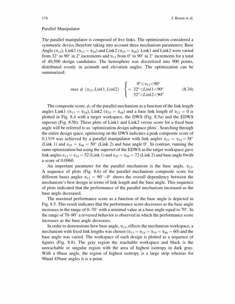
The composite score,f, of the parallel mechanism as a function of the link length
angles Link1 (a13 ¼ a24), Link2 (a35 ¼ a46) and a base link length of a12 ¼ 0 is
plotted in Fig. 8.4 with a target workspace, the DWS (Fig. 8.5a) and the EDWS
superset (Fig. 8.5b). These plots of Link1 and Link2 versus score for a fixed base
angle will be referred to as ‘optimization design subspace plots’. Searching through
the entire design space, optimizing on the DWS indicates a peak composite score of
0.1319 was achieved by a parallel manipulator with link angles a13 ¼ a24¼ 38�
(Link 1) and a35 ¼ a46 ¼ 50� (Link 2) and base angle 0�. In contrast, running the
same optimization but using the superset of the EDWS as the target workspace gave
link angles a13¼ a24¼ 52 (Link 1) and a35¼ a46¼ 72 (Link 2) and base angle 0with
a score of 0.0960.
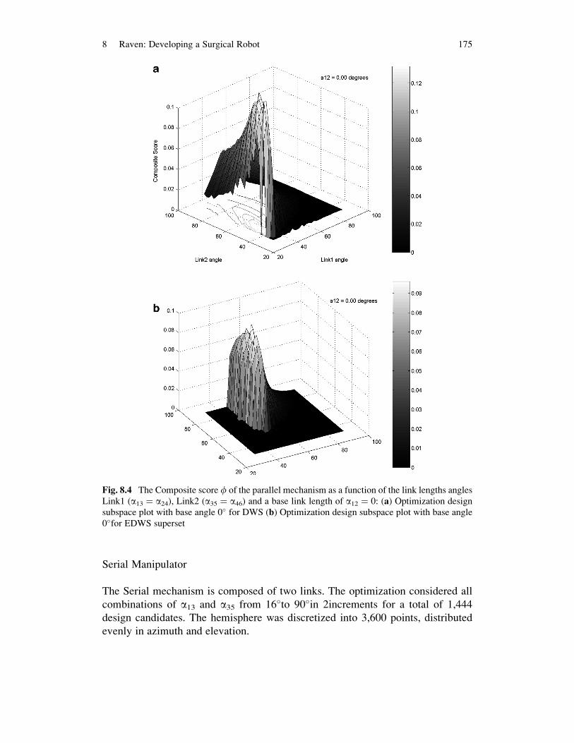
An important parameter for the parallel mechanism is the base angle, a12.A sequence of plots (Fig. 8.6) of the parallel mechanism composite score for
different bases angles a12 ¼ 90��0� shows the overall dependency between the
mechanism’s best design in terms of link length and the base angle. This sequence
of plots indicated that the performance of the parallel mechanism increased as the
base angle decreased.
The maximal performance score as a function of the base angle is depicted in
Fig. 8.5. This result indicates that the performance score decreases as the base angle
increases in the range of 0–70� with a minimal value at a base angle equal to 70�. Inthe range of 70–90� a reversed behavior is observed in which the performance score
increases as the base angle decreases.
In order to demonstrate how base angle, a12, effects the mechanism workspace, a
mechanism with fixed link lengths was chosen (a13¼ a24¼ a35¼ a46¼ 60) and the
base angle was varied. The workspace of each design is plotted as a sequence of
figures (Fig. 8.8). The gray region the reachable workspace and black is the
unreachable or singular region with the area of highest isotropy in dark gray.
With a 0base angle, the region of highest isotropy is a large strip whereas for
90and 45base angles it is a point.
174 J. Rosen et al.
Serial Manipulator
The Serial mechanism is composed of two links. The optimization considered all
combinations of a13 and a35 from 16�to 90�in 2increments for a total of 1,444
design candidates. The hemisphere was discretized into 3,600 points, distributed
evenly in azimuth and elevation.
Fig. 8.4 The Composite score f of the parallel mechanism as a function of the link lengths angles
Link1 (a13 ¼ a24), Link2 (a35 ¼ a46) and a base link length of a12 ¼ 0: (a) Optimization design
subspace plot with base angle 0� for DWS (b) Optimization design subspace plot with base angle
0�for EDWS superset
8 Raven: Developing a Surgical Robot 175
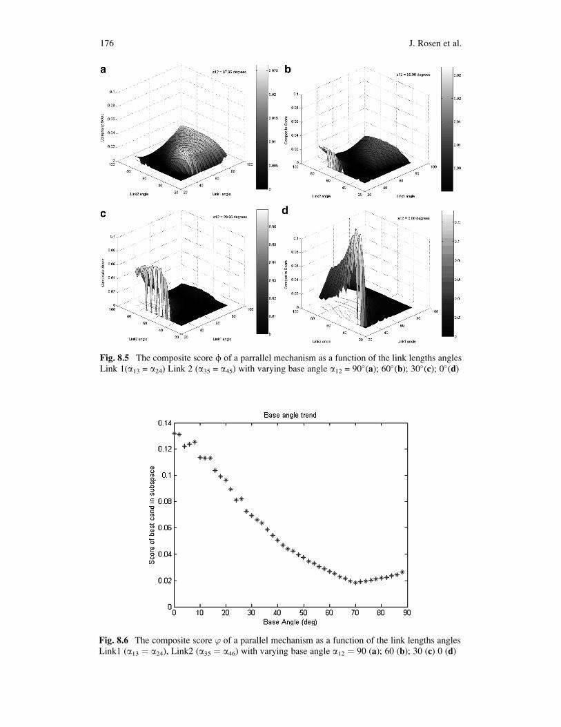
Fig. 8.5 The composite score f of a parrallel mechanism as a function of the link lengths angles
Link 1(a13 = a24) Link 2 (a35 = a45) with varying base angle a12 = 90�(a); 60�(b); 30�(c); 0�(d)
Fig. 8.6 The composite score ’ of a parallel mechanism as a function of the link lengths angles
Link1 (a13 ¼ a24), Link2 (a35 ¼ a46) with varying base angle a12 ¼ 90 (a); 60 (b); 30 (c) 0 (d)
176 J. Rosen et al.
max f ða13; a35Þ 16o<a13<90o
16o<a35<90o
(8.35)
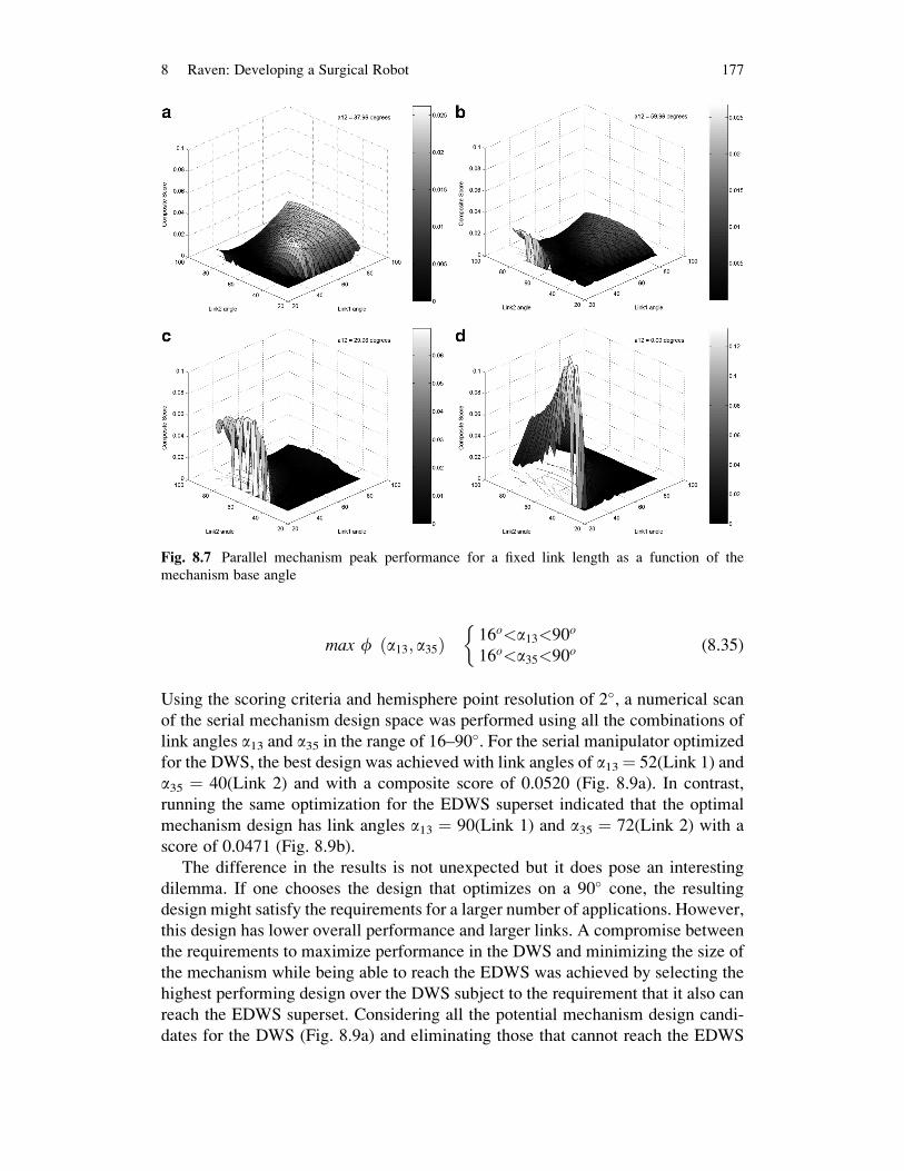
Using the scoring criteria and hemisphere point resolution of 2�, a numerical scan
of the serial mechanism design space was performed using all the combinations of
link angles a13 and a35 in the range of 16–90�. For the serial manipulator optimized
for the DWS, the best design was achieved with link angles of a13¼ 52(Link 1) and
a35 ¼ 40(Link 2) and with a composite score of 0.0520 (Fig. 8.9a). In contrast,
running the same optimization for the EDWS superset indicated that the optimal
mechanism design has link angles a13 ¼ 90(Link 1) and a35 ¼ 72(Link 2) with a
score of 0.0471 (Fig. 8.9b).
The difference in the results is not unexpected but it does pose an interesting
dilemma. If one chooses the design that optimizes on a 90� cone, the resulting
design might satisfy the requirements for a larger number of applications. However,
this design has lower overall performance and larger links. A compromise between
the requirements to maximize performance in the DWS and minimizing the size of
the mechanism while being able to reach the EDWS was achieved by selecting the
highest performing design over the DWS subject to the requirement that it also can
reach the EDWS superset. Considering all the potential mechanism design candi-
dates for the DWS (Fig. 8.9a) and eliminating those that cannot reach the EDWS
Fig. 8.7 Parallel mechanism peak performance for a fixed link length as a function of the
mechanism base angle
8 Raven: Developing a Surgical Robot 177

give the subset plotted in Fig. 8.9e. The highest performing design from this subset
had link angles of a13 ¼ 74� and a35 ¼ 60� and a score of 0.0367.
8.3 System Architecture and Integration
The system includes two main sub systems: (1) the surgical console (master) and
(2) the surgical robot (slave). To enable teleportation the master and the slave may
be connected through various network layers for example wired, wireless, and
hybrid communication links. Figure 8.10 provide an overview of the system
architecture. The surgeon initiates the movement of the robot by moving the taylus
of a haptic master input device. The position of the stylus is sensed by position
sensors embedded in the master joints and acquired by the A/D converter that is
Fig. 8.8 The parallel mechanism workspace link lengths: a13 ¼ a24 ¼ a35 ¼ a46 ¼ 60�as a
function of base angle a12 ¼ 90�(a); 45�(b); 0�(c)
178 J. Rosen et al.
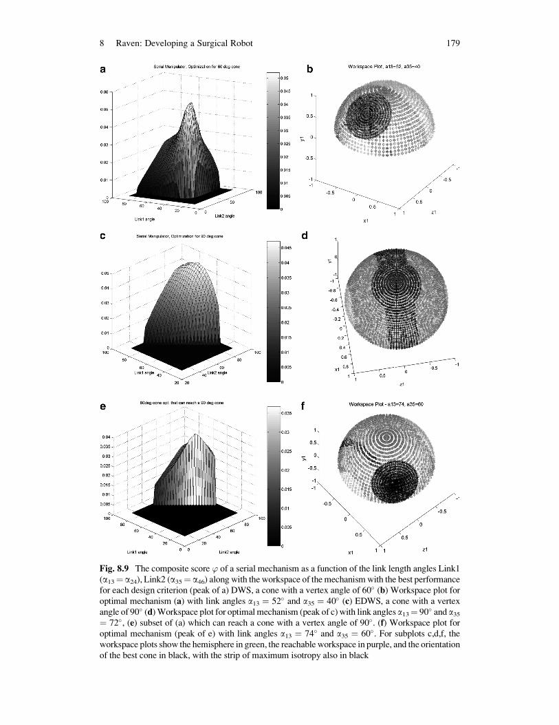
Fig. 8.9 The composite score ’ of a serial mechanism as a function of the link length angles Link1
(a13¼ a24), Link2 (a35¼ a46) along with the workspace of the mechanismwith the best performance
for each design criterion (peak of a) DWS, a cone with a vertex angle of 60� (b) Workspace plot for
optimal mechanism (a) with link angles a13 ¼ 52� and a35 ¼ 40� (c) EDWS, a cone with a vertex
angle of 90� (d)Workspace plot for optimalmechanism (peak of c)with link angles a13¼ 90� and a35¼ 72�, (e) subset of (a) which can reach a cone with a vertex angle of 90�. (f) Workspace plot for
optimal mechanism (peak of e) with link angles a13 ¼ 74� and a35 ¼ 60�. For subplots c,d,f, theworkspace plots show the hemisphere in green, the reachable workspace in purple, and the orientation
of the best cone in black, with the strip of maximum isotropy also in black
8 Raven: Developing a Surgical Robot 179
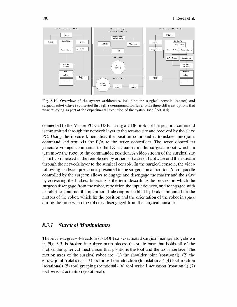
connected to the Master PC via USB. Using a UDP protocol the position command
is transmitted through the network layer to the remote site and received by the slave
PC. Using the inverse kinematics, the position command is translated into joint
command and sent via the D/A to the servo controllers. The servo controllers
generate voltage commands to the DC actuators of the surgical robot which in
turn move the robot to the commanded position. A video stream of the surgical site
is first compressed in the remote site by either software or hardware and then stream
through the network layer to the surgical console. In the surgical console, the video
following its decompression is presented to the surgeon on a monitor. A foot paddle
controlled by the surgeon allows to engage and disengage the master and the salve
by activating the brakes. Indexing is the term describing the process in which the
surgeon disengage from the robot, reposition the input devices, and reengaged with
to robot to continue the operation. Indexing is enabled by brakes mounted on the
motors of the robot, which fix the position and the orientation of the robot in space
during the time when the robot is disengaged from the surgical console.
8.3.1 Surgical Manipulators
The seven-degree-of-freedom (7-DOF) cable-actuated surgical manipulator, shown
in Fig. 8.5, is broken into three main pieces: the static base that holds all of the
motors the spherical mechanism that positions the tool and the tool interface. The
motion axes of the surgical robot are: (1) the shoulder joint (rotational); (2) the
elbow joint (rotational) (3) tool insertion/retraction (translational) (4) tool rotation
(rotational) (5) tool grasping (rotational) (6) tool wrist-1 actuation (rotational) (7)
tool wrist-2 actuation (rotational).
Fig. 8.10 Overview of the system architecture including the surgical console (master) and
surgical robot (slave) connected through a communication layer with three different options that
were studying as part of the experimental evolution of the system (see Sect. 8.4)
180 J. Rosen et al.

The first four joint axes intersect at the surgical port location, creating a spherical
mechanism that allows for tool manipulation similar to manual laparoscopy.
Themechanism links aremachined fromaluminum, and are generally I-section shapes
with structural covers. These removable covers allow access to the cable system,while
improving the torsional stiffnessof the links.The links are alsooffset fromthe joint axis
planes, allowing for a tighter minimum closing angle of the elbow joint.
The RAVEN utilizes DC brushless motors located on the stationary base, which
actuate all motion axes. Maxon EC-40motors with 12:1 planetary gearboxes are used
for the first three axes, which see the highest forces. The first two axes, those under the
greatest gravity load, have power-off brakes to prevent tool motion in the event of a
power failure. The fourth axis uses an EC-40 without a gearbox, and Maxon EC-32
motors are used for the remaining axes.MaxonDES70/10 series amplifiers drive these
brushless motors. The motors are mounted onto the base via quick-change plates that
allow motors to be replaced without the need to disassemble the cable system.
The cable transmission system comprises a capstan on each motor, a pretension
adjustment pulley, various pulleys to redirect the cables through the links, and a
termination point to each motion axis. The shoulder axis is terminated on a
single partial pulley. The elbow axis has a dual-capstan reduction stage terminating
on a partial pulley. The tool insertion/ retraction axis has direct terminations of the
cables on the tool holder. The tool rotation, grasping, andwrist cables are terminated on
capstans on the tool interface. The cable system transmission ratios for positioning the
tool tip are as follows. (1) Shoulder: 7.7:1 (motor rotations:joint rotations); (2) Elbow:
7.3:1 (motor rotations:joint rotations); (3) Insertion: 133:1 (radians:meters).
Each axis is controlled by two cables, one for motion in each direction, and these
two cables are pre-tensioned against each other. The cables are terminated at each
end to prevent any possibility of slipping. The cable system maintains constant
pretension on the cables through the entire range of motion. Force and motion
coupling between the axes is accommodated for in the control system.
Laser pointers attached to the shoulder and elbow joints allow for visual alignment
of the manipulator relative to the surgical port.When the two dots converge at the port
location, the manipulator is positioned such that its center of rotation is aligned with
the pivot point on the abdominal wall. The power-off brakes can be released by
flipping a switch located on the base. The brakes are normally powered by the control
electronics, but also have a battery plug-in for easy set-up and breakdown when the
system is not powered.ABS plastic coverswere created on a three-dimensional printer
to encapsulate the motor pack thereby protecting actuators, encoders and electrical
wiring. Figure 8.11b shows the complete patient site.
8.4 Experimental Evaluation
The methodology is divided into two sections: field experiments and lab
experiments that were performed with Raven [24–27, 38–43]. The field experiments
were used in part to define latencies associated with different configurations of
8 Raven: Developing a Surgical Robot 181
network architectures. Based on this information discrete and fixed time delays were
selected and emulated in controlled lab experiments.
8.4.1 Preliminary Experimental Evaluation
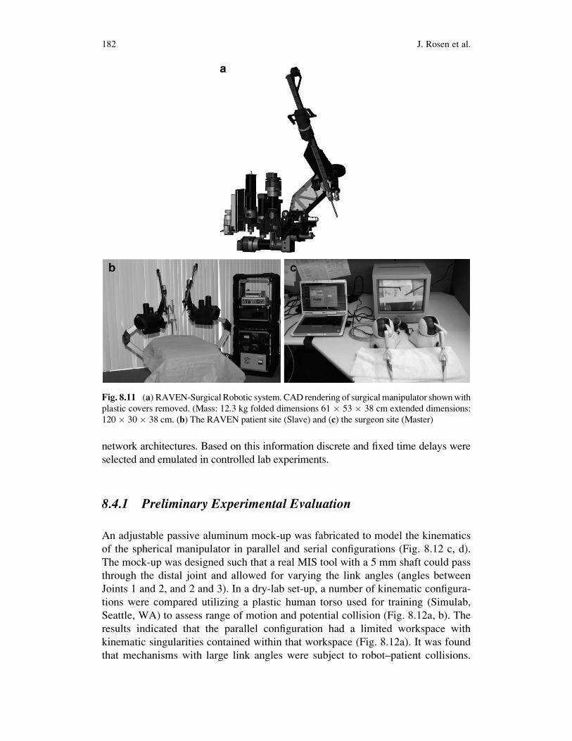
An adjustable passive aluminum mock-up was fabricated to model the kinematics
of the spherical manipulator in parallel and serial configurations (Fig. 8.12 c, d).
The mock-up was designed such that a real MIS tool with a 5 mm shaft could pass
through the distal joint and allowed for varying the link angles (angles between
Joints 1 and 2, and 2 and 3). In a dry-lab set-up, a number of kinematic configura-
tions were compared utilizing a plastic human torso used for training (Simulab,
Seattle, WA) to assess range of motion and potential collision (Fig. 8.12a, b). The
results indicated that the parallel configuration had a limited workspace with
kinematic singularities contained within that workspace (Fig. 8.12a). It was found
that mechanisms with large link angles were subject to robot–patient collisions.
Fig. 8.11 (a) RAVEN-Surgical Robotic system. CAD rendering of surgical manipulator shownwith
plastic covers removed. (Mass: 12.3 kg folded dimensions 61 � 53 � 38 cm extended dimensions:
120 � 30 � 38 cm. (b) The RAVEN patient site (Slave) and (c) the surgeon site (Master)
182 J. Rosen et al.

Using two parallel mechanisms created potential self-collisions and constrained the
distance between the two mechanisms, even with the link angles chosen as small as
possible. Similar problems and constraints were observed for a hybrid configuration
with a combination of one serial and one parallel mechanism. The best performance
in terms of avoiding self-collision and robot–patient collision was achieved with
both mechanisms in serial configuration (Fig. 8.12b).
Using two serial configurations in an experimental surgery with an animal
model, surgeons confirmed that the serial 2-link with the dimensions given by the
analytical optimization provided sufficient range of motion and did not suffer from
self-collision, robot–robot collision, or robot–patient collision during both gross
and dexterous manipulations (Fig. 8.12e).
Fig. 8.12 AluminumMock-upwith adjustable link length and base length. The surgical endo-scopic
tool is inserted into a guide located at mechanism apex in a configuration that allow to test different
design candidates in a real minimally invasive surgical setup. (a) Parallel Configuration (b) Serial
Configuration (c, d) Two configurations tested in a MIS setup. (e) Testing the make up in an animal
lab. Although the robot manipulator will be teleoperated, in this evaluation the surgeon guides these
passive mock-ups in order to evaluate the range of motion
8 Raven: Developing a Surgical Robot 183

8.4.2 Field Experiments
8.4.2.1 Flied Experiments
Seven field experiments were conducted with Raven with various network
architectures (wired and wireless) and a wide spectrum of physical distances
(Table 8.4). In experiment No. 1 (HAPs/MRT) the system was deployed in two
remote sites in desert-like conditions in Simi Valley, CA, while utilizing an
Unmanned Aerial Vehicle (UAV) as a wireless node between the sites. In Experi-
ment No. 2, (Imperial College London Collaboration), 6 (Surgical Robot Summer
School) and 7 (Tokyo Tech Collaboration), the surgical robot located in Seattle was
teleoperated from different sites around the world using commercial internet.
In experiments 4 and 5 the surgical robot was deployed in the Aquarius – an undersea
habitat, located 3.5 km off-shore in the Florida Keys, and teleoperated from Seattle,
WA as well as the National Undersea Research Center, at Key Largo, FL using a
combination of wired and wireless communication as part of NASA’s NEEMO
(NASA Extreme Environment Mission Operations) 12 mission (Fig. 8.13).
8.4.2.2 Lab Experiments
System Setup
In a real teleoperation, physical distance and a real network separate the patient and
surgeons sites with time varying delays (Fig. 8.14). When a surgeon makes a
gesture using the master device, motion information is sent through the network
to the Patient Site with a network time delay (Tn). The manipulator moves and the
Fig. 8.13 Field Experiments – Image Gallery (a) The surgical console (b) Overview of the
surgical site as it is presented to the surgeon during the NEEMO 12 mission (c) Raven located
in AQUARIUS during the NEEMO 12 mission (d) Panoramic view of the of the HAPs/MRT
experimental setup
184 J. Rosen et al.

Table
8.4
Summaryoffieldexperim
entswithRaven
No.
Acronym
Patientsite
(Slave)
surgical
robot
Surgeonsite
(Master)surgical
console
Communication
layer
video
Communicationlayer
network
architecture
Tim
edelay
(ms)(a)
Distance
(km]
1HAPs/MRT
Field
–simivalley,
CA
Field
–simivalley,
CA
HaiVision,
Hai560
Wirelessvia
UAV
16
0.5
2ICL
Seattle,WA
London,UK
iChat/Skype
Commercial
internet
172
7,700
3AnimalLab
Seattle,WA
Seattle,WA
DirectS-V
ideo
LAN
10
4NEEMO12–Aqu
arius
Aquarius
(underwater),
Key
Largo,FL
Seattle,WA
HaiVision,
Hai1000
Commercial
internet
–seattleWA
tokey
Largo,FLmicrowave
Comm.–Key
Largo,FL
toAquarius
76
4,500
5NEEMO12
–NURC
NURC(land),Key
Largo,FL
Seattle,WA
HaiVision,
Hai200
Commercial
internet
75
4,500
6Su
rgical
Robot–Course
Seattle,WA
Montpellier,
France
iChat/Skype
Com
mercial
Internet
170
8,500
7Tokyo
TechCollabo
ration
Seattle,WA
Tokyo,Japan
iChat/Skype
Commercial
Internet
150
7,600
aThetimedelay
refers
tothelatency
insendingpositioncommandsbetweenthemuster
andthesalve.
Thelatency
regardingthevideo
transm
ission,
compressionanddecompressionwas
notrecorded
8 Raven: Developing a Surgical Robot 185
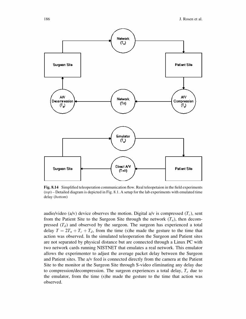
audio/video (a/v) device observes the motion. Digital a/v is compressed (Tc), sentfrom the Patient Site to the Surgeon Site through the network (Tn), then decom-
pressed (Td) and observed by the surgeon. The surgeon has experienced a total
delay T ¼ 2Tn þ Tc þ Td, from the time (s)he made the gesture to the time that
action was observed. In the simulated teleoperation the Surgeon and Patient sites
are not separated by physical distance but are connected through a Linux PC with
two network cards running NISTNET that emulates a real network. This emulator
allows the experimenter to adjust the average packet delay between the Surgeon
and Patient sites. The a/v feed is connected directly from the camera at the Patient
Site to the monitor at the Surgeon Site through S-video eliminating any delay due
to compression/decompression. The surgeon experiences a total delay, Te due to
the emulator, from the time (s)he made the gesture to the time that action was
observed.
Fig. 8.14 Simplified teleoperation communication flow. Real teleopetaion in the field experiments
(top) – Detailed diagram is depicted in Fig. 8.1. A setup for the lab experiments with emulated time
delay (bottom)
186 J. Rosen et al.

Experimental Design
The Society of American Gastrointestinal and Endoscopic Surgeons (SAGES)
developed a curriculum for teaching the Fundamentals of Laparoscopic Surgery
(FLS) which includes both cognitive and psychomotor skills. The skills assessment
consists of five tasks. The FLS skills tasks have been validated to show significant
correlation between score and postgraduate year and are considered by many the
“gold standard” in surgical skill assessment. The Block Transfer is one out of these
five tasks that emulate tissue handling and manipulation.
The experimental task consists of moving six blocks, one at a time, from the left
side of the FLS peg board (Fig. 8.15) to the right side and back to the original
position in a sequential predefined order (total of 12 transfers). In our experiment,
the completion time as well as the tool tip trajectory were recorded. The three
treatments of the experiment included emulated delays of 0, 250 and 500 ms
presented to the subjects in randomized order. Each experimental treatment was
conducted three times by each subject (nine times total) in a randomized order.
The subjects performed the training tasks first with no delay then with 250 ms
delay in order to learn how to teleoperate the RAVEN and minimize the learning
effects during the execution of the experimental protocol. Within 1 week from the
start of their training, they returned to perform the time delayed block transfer
experiment.
Subjects: Definition of the Population
Fourteen subjects, five surgeon and nine non-surgeons, ages ranging from 18 to 43,
participated in this study under University of Washington Human Subjects
Approval Number 01-825-E/B07.
Fig. 8.15 The Society of American Gastrointestinal and Endoscopic Surgeons (SAGES)
Fundamental Laaproscopic Skill (FLS) Block Transfer task board set up with the RAVEN
8 Raven: Developing a Surgical Robot 187

8.4.3 Results
8.4.3.1 Field Experiments
Given the stochastic nature of the network there is a specific distribution of packet
delay. Figure 8.16 depicts the distribution of the delay during the NEEMO experi-
ments given a transmission rate of 1 K. The distribution of the latency is in the range
of 63–95 ms with a pick at 78 ms. Table 8.1 defines the average latencies during all
the field experiments. One should note that these latencies represent only the delay
in sending position command from the master to the slave (Tn). The latency due to
the digital a/v compressed (Tc) and decompressed (Td) which is usually larger and
hardware/software dependent and is estimated to be in the range of 200 ms
(hardware compression/decompression) in the HAPs/MRT and about 1 s for the
commercial internet (software compression/decompression).
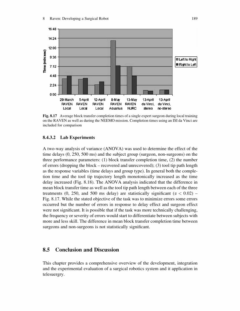
Figure 8.17 summarizes the mean completion time for a single expert surgeon
(E1) who participated in multiple field and lab experiments performing the block
transfer task. In each of the first 3 weeks of training, E1 performed three repetitions
of the Block Transfer in the lab environment with effectively no delay. There is a
learning effect as E1’s mean time improved from week to week. During the
NEEMO mission E1 completed a single repetition of the task with the RAVEN in
Aquarius and another single repetition with it on-shore in NURC Key Largo, FL.
For comparison, E1, who uses a da Vinci clinically was able to complete the block
transfer task in about 1 min using the da Vinci, taking only slightly longer with the
stereo capability disabled.
Fig. 8.16 Histogram of number of packets with respect to delay between Seattle WA and
Aquarius, Key Largo, FL at a transmission/receiving frequency of 1 K
188 J. Rosen et al.
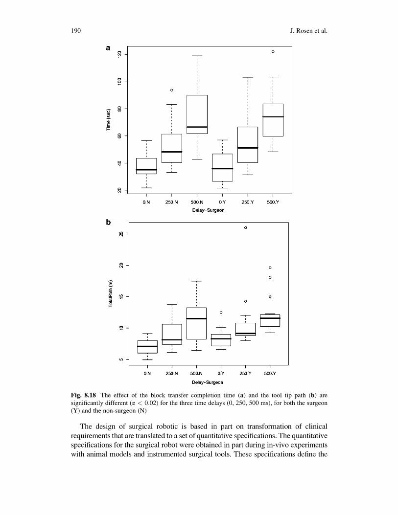
8.4.3.2 Lab Experiments
A two-way analysis of variance (ANOVA) was used to determine the effect of the
time delays (0, 250, 500 ms) and the subject group (surgeon, non-surgeons) on the
three performance parameters: (1) block transfer completion time, (2) the number
of errors (dropping the block – recovered and unrecovered); (3) tool tip path length
as the response variables (time delays and group type). In general both the comple-
tion time and the tool tip trajectory length monotonically increased as the time
delay increased (Fig. 8.18). The ANOVA analysis indicated that the difference in
mean block transfer time as well as the tool tip path length between each of the three
treatments (0, 250, and 500 ms delay) are statistically significant (a < 0:02) –
Fig. 8.17. While the stated objective of the task was to minimize errors some errors
occurred but the number of errors in response to delay effect and surgeon effect
were not significant. It is possible that if the task was more technically challenging,
the frequency or severity of errors would start to differentiate between subjects with
more and less skill. The difference in mean block transfer completion time between
surgeons and non-surgeons is not statistically significant.
8.5 Conclusion and Discussion
This chapter provides a comprehensive overview of the development, integration
and the experimental evaluation of a surgical robotics system and it application in
telesuergry.
Fig. 8.17 Average block transfer completion times of a single expert surgeon during local training
on the RAVEN as well as during the NEEMOmission. Completion times using an ISI da Vinci are
included for comparison
8 Raven: Developing a Surgical Robot 189
The design of surgical robotic is based in part on transformation of clinical
requirements that are translated to a set of quantitative specifications. The quantitative
specifications for the surgical robot were obtained in part during in-vivo experiments
with animal models and instrumented surgical tools. These specifications define the
Fig. 8.18 The effect of the block transfer completion time (a) and the tool tip path (b) are
significantly different (a < 0:02) for the three time delays (0, 250, 500 ms), for both the surgeon
(Y) and the non-surgeon (N)
190 J. Rosen et al.

workspace of the surgical tools along with and the loads applied on the tissues through
the surgical tools in a MIS setup. The quantitative specifications enable a formal
mechanism optimization that led to the smallest mechanism with the highest manipu-
lability whichmeets the clinical requirements. As apart of the optimization process the
kinematic equations of parallel, and serial spherical manipulators with link length
angles less than 90�. The optimization cost function balanced a guaranteed minimum
isotropy and summed isotropy over the target workspacewithminimal total link length
in order to yield a very compact, high-dexterity mechanism. Given the definitions of
the DWS as the highly dexterous workspace and the EDWS as a reachable workspace
associatedwithMIS, the parallelmanipulatorwith the highest composite score had link
angles of a13 ¼ a24 ¼ 52� (Link 1) and a35 ¼ a46 ¼ 72� (Link 2) and base angle
a12¼ 0�. Given the same constrains the serial manipulator with the highest composite
score is the one with link angles of a13 ¼ 74� (Link 1) and a35 ¼ 60� (Link 2).The base angle a12 of the parallel manipulator has a profound influence on
the workspace of the mechanism as well as its composite score. The reachable
workspace of the parallel manipulator can be defined as the intersection of the
workspaces of the left serial link and the right serial link arms acting as independent
serial manipulators. When the base angle is zero, these two workspaces have a
maximum overlap and therefore more space in which to place the required work-
space cone that led to the highest performance score.
As the base angle, a12 was varied from 90� to 0� the performance score first
decreased, then increased, with a maximal value at a base angle of 0� and a minimal
value at a base angle of 70�. In order to understand the relationships between the
performance score as a function of the base angle, Link1 and Link2 were fixed at
angle of 60� (a13¼ a24¼ a35¼ a46¼ 60�) and the base angle varied. A sequence of
plots shows how the singular region that bisects the workspace moves with varying
base angles(Fig. 8.8). When the base angle is 90�, the overlap between the odd and
even sides is smaller, and the singular region is near the edge of the parallel
workspace. Decreasing the base angle to 45�increases the overall workspace but
moves the singular region more toward the middle of the workspace, thereby
decreasing the usable workspace because the cone must not contain any singula-
rities. Decreasing the base angle to 0�results in maximum workspace and moves the
singularity down below the joint limits guaranteeing the reachable workspace that
contains no singularities.
Optimization of the parallel mechanism shows that for a fixed base angle, better
performance would be achieved by a mechanism design where the angle of Link2 is
greater than that of Link1 (a13< a35 and a24< a46). Based on a spherical geometry,
if Link2 is greater than Link1 and the base angle is 0, then the parallel mechanism
cannot be put into a singular configuration.
The results for the serial mechanism showed good performance in a small form
factor. For any serial design there exists a strip of maximum isotropy across
the reachable workspace. This corresponds to a pose where y3 is some specific
value and y1 can be varied. As the link lengths get larger the strip of best
performance pushes away from the base (located at Joint 1), yet remains roughly
centered in the overall workspace (Fig. 8.9b, d, f).
8 Raven: Developing a Surgical Robot 191
Fabricating passive aluminum mock-ups of the mechanism under study was
critical to the evaluation of this class of manipulator for MIS applications. Through
evaluation of various combinations of parallel and serial configurations, it was
determined that two serial manipulators provide the smallest footprint and the
fewest collisions in the common cases where two or more mechanisms occupy
the limited space above the patient body. Based on the kinematic optimization, the
link angles of these serial manipulators should be 74�for the first link and 60�for thesecond link. This configuration and design of manipulators results in the most
compact mechanism that will perform MIS procedures with high dexterity in the
entire workspace required.
The system integration of a surgical robot is an immense engineering effort that
was resulted in an open architecture surgical robotic system that enables a wide
spectrum of studies in surgical robotics and teleoperation. The chapter provides an
overview of lab and field experiments studying the effect of time delay on surgical
performance. A subset of a standard set of tasks (Fundamentals of Laparoscopic
Surgery – FLS), which adopted by the MIS surgical community many surgical
residency training programs was used in the majority of the field experiments and
all the lab experiments. Block transfer emulating tissue handling along with suturing
and knot tying defined the subset of the FLS that was adopted for the telerobotics
experiments. Time delay is an embedded characteristic of any network. As indicated
in the field experiments the latency related to the compression/and decompression of
the audio/video (a/v) is significantly larger then the latency related to the transmis-
sion of position commands between the master and the slave. As such the a/v
transmission latency is the limiting factor that determines the overall performance
of the system. The results acquired in the lab experiments indicated a degradation of
teleoperation performance characterized by increased completion time and tool path
length, which were used as performance measures.
8.6 Visions
The premise of surgical robotics is to deliver high level of dexterity and enhance
view of anatomical structures that is either too small or difficult to access (expose)
for conventional surgical tools, the surgeons’ fingers and a line of site. An approach
to this anatomical structure may use either an open surgery technique, MIS or
minimally access techniques that were otherwise. Aviation is often used a sources
of inspiration for surgery. In both of these frameworks the pilot and the surgeon
have to deal with complex system with high level situation awareness to communi-
cate with additional individuals such as Co-Pilot and air traffic control personal in
the aviation domain, and nurses (circulation nurse or sterile nurse) along with co-
surgeons, and anesthesiologist in the surgery domain in addition to the immediate
interaction with the system which is the airplane in aviation and the surgical
site during surgery. Regardless of the many similarities between the two domains
one should note that there is one fundamental difference between them. In aviation
192 J. Rosen et al.
the goal is to fly an airplane from point A to Point B with minimal interaction with
the environment. However in surgery the goal is to change the environment
(anatomical structure) in order to alter its function.
Although in small aircraft the pilot control the airplane through the stick which is
analogues to a surgeon holding a surgical tool, automation is a concept that is
widely used in a form of an automatic pilot in commercial and military airplanes.
Automation in this context removes the human form the low-level operation (e.g.
correcting a drift in the airplane flight path or manipulating the soft tissue due to
deformation in surgery) and reposition the pilot or the surgeon as a high-level
decision maker using supervisory control mode with interrupted intervention in
critical steps of the operation.
With the introduction of a surgical robot automation in surgery can be imple-
mented at two different levels: (1) system services and (2) surgical operation. The
Trauma Pod project as envisioned by Dr. Richard Satava and its translation into
practice as part of the a phase 1 DARPA project (see for details the chapter by Pablo
Garcia) demonstrated that services to the surgical robot along with overall operating
room (OR) management can be fully automated. The end-result was a fully auto-
mated operating room in which the only human in the OR may be only the patient.
A centralized robotic surgical nurse provided services to the surgical robot such as
tool dispensing from an automatic tool changer and changing, as well as equipment
dispensing and disposing from an automatic equipment dispenser, vital signs moni-
toring, and overall supply chain management (inventory monitoring) – actions that
took place upon voice command by a surgeon interacting with the surgical console.
A far as services to the surgical robot are concerned (tool change and equipment
dispensing) centralized solution was used in a form of a single surgical nurse. As a
result the performance of the entire system in providing these two services is
dictated by the performance of the surgical nurse alone. An alternative approach
in which each surgical robot is attached to another robotic arm in a micro–macro
configuration, allows each surgical robot to be an independent unit that may serve
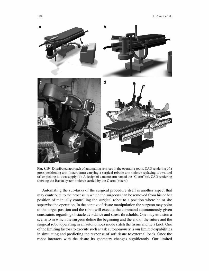
itself (replacing it own tools and picking its own supplies) – Fig. 8.19. In this
configuration the nurse function is distributed among all the robotics arms allowing
each one to function autonomously.
The micro–macro approach to surgical robotics in which a gross manipulator
carry a high dexterous manipulator is inspired by the human arm and hand in which
the human arm serves as the gross manipulator positions the wrist in space for high
dexterity manipulation by the hand. This approach may allow to design small and
fast responding manipulator with high manipulability in a limited workspace which
occupy only a subset of the surgical site (micro) and mount it on a land slow
manipulator with a large workspace (macro). The macro manipulator may move the
base of the micro manipulator in case it will sense the micro manipulator operates
close to the edge of its workspace. The movement is obviously transparent to the
surgeon who should not be involved nor aware of these adjustments of workspaces.
This distributed architecture from the functional perspective may also allow to
distribute the surgical robotics arm around the patients in a way that will avoid
robot to robot collision.
8 Raven: Developing a Surgical Robot 193
Automating the sub-tasks of the surgical procedure itself is another aspect that
may contribute to the process in which the surgeons can be removed from his or her
position of manually controlling the surgical robot to a position where he or she
supervise the operation. In the context of tissue manipulation the surgeon may point
to the target position and the robot will execute the command autonomously given
constraints regarding obstacle avoidance and stress thresholds. One may envision a
scenario in which the surgeon define the beginning and the end of the suture and the
surgical robot operating in an autonomous mode stitch the tissue and tie a knot. One
of the limiting factors to execute such a task autonomously is our limited capabilities
in simulating and predicting the response of soft tissue to external loads. Once the
robot interacts with the tissue its geometry changes significantly. Our limited
Fig. 8.19 Distributed approach of automating services in the operating room. CAD rendering of a
gross positioning arm (macro arm) carrying a surgical robotic arm (micro) replacing it own tool
(a) or picking its own supply (b). A design of a macro arm named the “C-arm” (c). CAD rendering
showing the Raven system (micro) carried by the C-arm (macro)
194 J. Rosen et al.
capabilities in predicting the soft tissue response are due to the non-linear, and
un-isotropic nature of soft tissues. Another futuristic scenario may involve auto-
matic edge detection and dissection of a tumor based on preoperative scans or
biomarker that may be injected into the tissue.
Introducing a robotic system into the OR and utilizing such a system clinically
was a major milestone for the field of surgical robotics. Emerging technologies
based on scientific discoveries will continue to flow into the surgical robotic
systems and provide better tool in the hands of the surgeons for delivering high
quality healthcare.
Acknowledgment Development of the RAVEN was supported by the US Army, MRMC,
grant number DAMD17-1-0202. The HAPs/MRT project was supported by the US Army
TATRC, grant number W81XWH-05-2-0080. The surgical robot development was a collaborative
team effort of students and faculty members in engineering and medicine who developed the
system over the years including: Mitchell J.H. Lum (EE), Hawkeye King (EE), Diana C.W.
Friedman (ME), Denny Trimble (ME), Thomas S. Lendvay (Children’s Hospital – Seattle),
Andrew S. Wright (Surgery), Mika N. Sinanan (Surgery). The authors would like to thank the
HAPs/MRT collaborators at the University of Cincinnati, AeroVironment, and HaiVision as well
as our collaborators in London at Imperial College and at Tokyo Tech. The NEEMO XII
participation has been supported by the US Army TATRC grant number W81XWH-07-2-0039.
The authors would like to thank the NEEMO collaborators from University of North Carolina at
Wilmington, US Navy, National Undersea Research Center, National Oceanographic and Atmo-
spheric Administration, NASA, and in particular, Dr. Timothy Broderick, Charles Doarn, and
Brett Harnett from the University of Cincinnati.
References
1. Satava, R.: Disruptive visions: the operating room of the future, Surg. Endosc. 17(1), 104–107
(2003)
2. Satava, R.M.: Surgical robotics: the early chronicles: a personal historical perspective, Surg.
Laparosc. Endosc. Percutan. Tech. 12, 6–16 (2002)
3. Satava, R.M.: Emerging technologies for surgery in the 21st century, Arch. Surg. 134,
1197–1202 (1999)
4. Howe, R.D., Matsuoka, Y.: Robotics for surgery. Ann. Rev. Biomed. Eng. 1, 211–240 (1999)
5. Buess, G.F., Schurr, M.O., Fischer, S.C.: Robotics and allied technologies in endoscopic
surgery, Arch. Surg. 135, 229–235 (2000)
6. Davies, B.: A review of robotics in surgery. Proc. Instn. Mech. Eng. 214(H), (2000)
7. Clearly, K., Nguyen, C.: State of the art in surgical robotics: clinical applications and
technology challenges. Comput. Aided Surg. 6, 312–328 (2001)
8. Bloom, M.B., Salzberg, A.B., Krummel, T.M.: Advanced technology in surgery. Curr. Probl.
Surg. 39(8), 733–830 (2002)
9. Taylor, R.H., Stoianovici, D.: Medical robotics in computer-integrated surgery, Robotics and
Automation. IEEE Trans. Robot. Autom. 19(5) 765–781 (2003)
10. Lanfranco, A.R., Castellanos, A.E., Desai, J.P., Meyers, W.C.: Robotic surgery a current
perspective. Ann. Surg. 239(1), 14–21 (2004)
11. Louw, D.F., Fielding, T., McBeth, P.B., Gregoris, D., Newhook, P., Sutherland, G.R.:
Surgical robotics: a review and neurosurgical prototype development. Nuerosurgery 54(3),
525–537 (2004)
8 Raven: Developing a Surgical Robot 195

12. Speich, J.E., Rosen, J.: Medical robotics, In: Wnek, G., Bowlin, G. (eds.) Encyclopedia of
Biomaterials and Biomedical Engineering, pp. 983–993. Marcel Dekker, New York (2004)
13. Binder, J., Br€autigam, R., Jonas, D., Bentas, W.: Robotic surgery in urology: fact or fantasy?
BJU Int. 94(8), 1183–1187 (2004)
14. Korb, W., Marmulla, R., Raczkowsky, J., M€uhling, J., Hassfeld, S.: Robots in the operating
theatre – chances and challenges, Int. J. Oral. Maxillofac. Surg. 33(8), 721–732 (2004)
15. Diodato, Jr, M.D. Prosad, S.M., Klingensmith, M.E., Damiano, Jr, R.J.: Robotics in surgery.
Curr. Probl. Surg. 41(9), 752–810(2004)
16. Camarillo, D.B., Krummel, T.M., Salisbury, J.K.: Robotic technology in surgery: past,
present, and future. Am. J. Surg. 188(Suppl to October 2004), 2S–15S (2004)
17. Curley, K.C.: An overview of the current state and uses of surgical robots. Oper. Tech. Gen.
Surg. 7(4), 155–164 (2005)
18. Kwoh, Y.S. Hou, J.L. Jonckheere, E.A., Hayall S.: A robot with improved absolute positioning
accuracy for ct guided stereotactic brain surgery. IEEE Trans. Biomed. Eng. 35(2), 153–161
(1988)
19. Takahashi, H., Warisawa, S., Mitsuishi, M., Arata, J., Hashizume, M.: Development of high
dexterity minimally invasive surgical system with augmented force feedback capability.
Biomedical Robotics and Biomechatronics, 2006. BioRob 2006. In: The First IEEE/RAS-
EMBS International Conference on, pp. 284–289 (2006)
20. Madhani, A.J. Niemeyer, G., Salisbury, Jr, J.K.: The black falcon: a teleoperated surgical
instrument for minimally invasive surgery. In: Proceedings of the Intelligent Robots and
Systems, vol. 2, pp. 936–944 (1998)
21. Cavusoglu, M.C. Tendick, F., Cohn, M., Sastry, S.S.: A laparoscopic telesurgical workstation.
IEEE Trans. Robot. Autom. 15(4), 728–739 (1999)
22. Marescaux, J.: Transatlantic robot-assisted telesurgery. Nature 413, 379–380 (2001)
23. Marescaux, J. Leroy, J., Rubino, F., Smith, M., Vix, M.,Simone, M., Mutter, D.: Transconti-
nental robot-assisted remote telesurgery: feasibility and potential applications advances in
surgical technique. Ann. Surg. 235(4), 487–492 (2002)
24. Rosen, J., Hannaford, B.: Doc at a distance. IEEE Spectrum, 34–38 (2006)
25. Sankaranarayanan, G., Hannaford, B., King, H., Ko, S.Y., Lum, M.J.H., Friedman, D., Rosen,
J., Hannaford, B.: Portable surgery master station for mobile robotic surgery. In: Proceedings
of the ROBOCOMM, the first International, conference on Robot Communication and
Coordination, Athens, Greece, Oct 2007
26. Brett, H., Doarn, C., Rosen, J., Hannaford, B., Broderick, T.J.: Evaluation of unmanned
airborne vehicles and mobile robotic telesurgery in an extreme environment, Telemed.
e-Health 14(6) 534–544 (2008)
27. Lum, M.J.H., Friedman, D.C.W., Sankaranarayanan, G., King, H., Fodero, II, K., Leuschke,
R., Hannaford, B., Rosen, J., Sinanan, M.N.: The RAVEN – a multidisciplinary approach to
developing a telesurgery system. Int. J. Robot. Res. Special Issue: Medical Robotics Part I 28
(9), 1183–1197 (2009)
28. Mitsuishi, M., Arata, J., Tanaka, K., Miyamotoamd, M., Yoshidome, T., Iwata, S., Hashizume,
M., Warisawa, S.: Development of a remote minimally-invasive surgical system with opera-
tional environment transmission capability. In: Robotics and Automation, 2003. Proceedings.
ICRA’03. IEEE International Conference, vol. 2, pp. 2663–2670 (2003)
29. Berkelman, P., Ji, M.: The University of Hawaii teleoperated robotic surgery system.
In: Intelligent Robots and Systems, 2007. IROS 2007. IEEE/RSJ International Conference
on, pp. 2565–2566, 29, 2 Nov 2007
30. Berkelman, P., Ji, M.: A compact, modular, teleoperated robotic minimally invasive surgery
system. In: Biomedical Robotics and Biomechatronics, 2006. BioRob 2006. The First IEEE/
RAS-EMBS International Conference (2006)
31. Rosen, J., Brown, J.D., Chang, L., Sinanan, M.N., Hannaford, B.: Generalized approach for
modeling minimally invasive surgery as a stochastic process using a discrete Markov model,
IEEE Trans. Biomed. Eng. 53(3), 399–413 (2006)
196 J. Rosen et al.

32. Rosen, J., MacFarlane, M.,Richards, C., Hannaford, B.,Pellegrini, C., Sinanan, M.N.: Surgeon/
Endoscopic Tool Force-Torque Signatures in the Evaluation of Surgical Skills During Mini-
mally Invasive Surgery, Studies in Health Technology and Informatics – Medicine Meets
Virtual Reality, vol. 62, pp. 290–296. IOS Press, Amsterdam (1999)
33. Rosen, J., Solazzo, M.,Hannaford, B., Sinanan, M.N.: Objective Laparoscopic Skills Assess-
ments of Surgical Residents Using Hidden Markov Models Based on Haptic Information and
Tool/Tissue Interactions, Studies in Health Technology and Informatics – Medicine Meets
Virtual Reality, vol. 81, pp.417–423. IOS Press, Amsterdam (2001)
34. Rosen, J., Brown, J.D., Barreca, M., Chang, L., Hannaford, B., Sinanan, M.N.: The Blue
DRAGON – a System for Monitoring the Kinematics and the Dynamics of Endoscopic Tools
in Minimally Invasive Surgery for Objective Laparoscopic Skill Assessment, Studies in
Health Technology and Informatics – Medicine Meets Virtual Reality, vol. 85, pp.412–418.
IOS Press, Amsterdam (2002)
35. Rosen, J, Brown, J.D., Chang, L., Barreca, M., Sinanan, M.N., Hannaford, B.: The blue
DRAGON – a system for measuring the kinematics and the dynamics of minimally invasive
surgical tools in-vivo. In: Proceedings of the 2002 IEEE International Conference on Robotics
& Automation, Washington DC, USA, 11–15 May 2002
36. Rosen, J., Chang, L., Brown, J.D., Hannaford, B., Sinanan, M.N., Satava, R.: Minimally
invasive surgery task decomposition – etymology of endoscopic suturing, studies in health
technology and informatics – medicine meets virtual reality, vol. 94, pp. 295–301. IOS Press,
Amsterdam (2003)
37. Taylor, R.H., Paul H.A., Brent, D., Mittelstadt et al.: Robotic Total Hip Replacement in days.
Proc 11 th IEEE Medicine & Biobgy Conft. pp. 887–892, Seattle, 1989
38. Lum, M.J.H., Rosen, J., King, H., Friedman, D.C.W., Donlin, G., Sankaranarayanan, G.,
Harnett, B., Huffman, L., Doarn, C., Broderick, T., Hannaford, B.: Telesurgery via unmanned
aerial vehicle (UAV) with a field deployable surgical robot. In: Proceedings of Medicine
Meets Virtual Reality (MMVR 15), pp. 313–315, Long Beach CA, 6–9 Feb 2007
39. Lum, M., Friedman, D., King, H., Donlin, R., Sankaranarayanan, G., Broderick, T., Sinanan,
M., Rosen, J., Hannaford, B.: Teleoperation of a surgical robot via airborne wireless radio and
transatlantic internet links. In: The 6th International Conference on Field and Service Robotics,
Chamonix, France, 9–12 Jul 2007
40. Lum, M.J.H., Friedman, D.C.W., Sankaranarayanan, G., King, H., Wright, A., Sinanan, M.N.,
Lendvay, T., Rosen, J., Hannaford, D.: Objective assessment of telesurgical robot systems:
telerobotic fls, medicine meets virtual reality (MMVR 16) pp. 263–265, Long Beach CA, Jan
29–Feb 1 2008
41. Lum, M.J.H., Rosen, J., Lendvay, T.S., Wright, A.S., Sinanan, M.N., Hannaford, B.: Tele-
Robotic fundamentals of laparoscopic surgery (FLS): effects of time delay – pilot study. In:
30th Annual International Conference of the IEEE Engineering in Medicine and Biology
Society EMBS, pp. 5597–5600, Vancouver, British Columbia, Canada, 20–25 Aug 2008
42. Lum, M.J.H., Rosen, J., Lendvay, T.S., Sinanan, M.N., Hannaford, B.: Effect of Time Delay
on TeleSurgical Performance. In: IEEE International Conference on Robotics and Automa-
tion, Kobe, Japan, 12–17 May 2009
43. Lum,M.J.H., Rosen, J., King, H., Friedman, D.C.W., Lendvay, T., Wright, A.S., Sinanan,M.N.,
Hannaford, B.: Teleopeartion in Surgical Robotics – Network Latency Effects on Surgical
Performance. In: 31th Annual International Conference of the IEEE Engineering in Medicine
and Biology Society EMBS, Minneapolis MN, Sept 2009
8 Raven: Developing a Surgical Robot 197


![LIE - PKU · Lie Lie . — Kazhdan Lusztig [36] Springer Springer 3 [36] Bernstein Kazhdan Sp(6) Springer q Springer (1) Goresky, Kottwitz MacPherson [26] κ Springer [26] Springer](https://static.fdocuments.net/doc/165x107/5ece7d203f11100e20750332/lie-lie-lie-a-kazhdan-lusztig-36-springer-springer-3-36-bernstein-kazhdan.jpg)


![Presentazione standard di PowerPoint - ALTAIR …metropolis.sci.univr.it/altair/wp-content/uploads/2014/07/...[Springer Handbook of Robotics 2008] ... Special Issue on Soft Actuators,](https://static.fdocuments.net/doc/165x107/5b3d06817f8b9a895a8dae7b/presentazione-standard-di-powerpoint-altair-springer-handbook-of-robotics-2008.jpg)