SURGICAL MANUAL · 9.2 Sterilization of the Cassette and Instruments 55 ... general health, the...
64
SURGICAL MANUAL GRAND MORSE ™
Transcript of SURGICAL MANUAL · 9.2 Sterilization of the Cassette and Instruments 55 ... general health, the...

SURGICAL MANUALGRAND MORSE™

THE GRAND MORSE™ IMPLANT SYSTEM


5
CONTENTS
1.0 BASIC INFORMATION ON SURGICAL PROCEDURES 8
2.0 NEODENT® IMPLANT SYSTEM 8
2.1 Overview 8
3.0 IMPLANT DESIGNS 11
3.1 Surface 12
3.1.1 NeoPoros 12
3.1.2 Acqua 13
3.2 Implant Options 14
3.2.1 Helix GM™ 14
3.2.2 Drive GM™ 14
3.2.3 Titamax GM™ 15
3.3 Options for Screw Threads and Overview of the Format According to
Implant Design 16
4.0 INDICATIONS AND CONTRAINDICATIONS 18
5.0 PREOPERATIVE PLANNING 19
5.1 Implant positioning and peri-implant tissue 19
5.1.1 Mesiodistal positioning of the implant 20
5.1.1.1 Examples of single teeth gaps 21
5.1.1.2 Examples of multiple teeth gaps 22
5.1.2 Buccal-lingual implant position 24
5.1.3 Cervicoapical position of the implant 24
5.2 Planning Aids 25
5.2.1 Space Planning Instrument for assisting in the diagnosis and positioning of implants 25

6
5.2.2 Direction indicators for for orientation of angulation and positioning 26
5.2.3 Surgical drill guide 28
6.0 SURGICAL PROCEDURES 29
6.1 Implant bed preparation 29
6.1.1 Basic implant bed preparation 29
6.1.1.1 Implant bed preparation for Helix GM™ tapered implants 31
6.1.1.2 Implant bed preparation for Drive GM™ tapered implants 34
6.1.1.3 Implant bed preparation for Titamax GM™ cylindrical implants 35
6.1.2 Details on special implant bed preparation 37
6.1.2.1 Tapered Contour Drill 37
6.1.2.1 Pilot Drill 38
6.1.2.3 Example of special implant bed preparation 38
6.1.2.4 Options for drills 40
6.2 Neodent® Implant Packaging 40
6.3 Placing of the Grand Morse™ Implant 42
6.3.1 Placing of the implant with the contra-angle handpiece 42
6.3.2 Manual placement of the implant 44
6.3.3 Completing the positioning of the implant with the Torque Wrench 44
6.3.4 Torque Wrench 45
6.4 Handling soft tissue 45
6.4.1 Two-step/submucosal healing 45
6.4.2 Transmucosal healing: one-step or immediate loading 49
6.4.2.1 Transmucosal healing: one-step 50

7
6.5 Overview of the healing abutments 51
6.5.1 Overview of Grand Morse™ abutments and corresponding healing abutments 52
6.5.1 Grand Morse™ Customizable Healing Abutments 53
7.0 HEALING PHASE 54
8.0 GENERAL PROSTHETIC GUIDELINES 54
9.0 NEODENT® KITS 55
9.1 Cleaning and Care of the Cassette and Instruments 55
9.2 Sterilization of the Cassette and Instruments 55
9.3 Cleaning and Care of the Drills 56
9.4 Drill Sterilization 57
BIBLIOGRAPHY 59

1.0 BASIC INFORMATION ON SURGICAL PROCEDURES
The modern era of implant dentistry is characterized as beginning in 1977 when the first clinical
results of osseointegration were first published1. Since then, dentistry has undergone significant changes.
The current treatment plan for patients usually offers implant-retained and/or implant-supported prostheses
as an accessible and reliable solution. The number of dental implants being placed has increased rapidly
in recent years,2,3 and this form of treatment requires specific knowledge and skills, which are relevant
to the results.4 Based on these facts, the objective of these guidelines is to provide dental surgeons and
specialists with basic information and guidelines on planning, surgical procedures and treatment options.
These guidelines do not substitute each product’s instructions for use (IFU). These can be found
at our website: www.ifu.neodent.com.br. It is the surgeon’s sole responsibility to analyze the patients’
general health, the viability of the surgical procedure and the most appropriate products for each clinical
situation.
2.1 Overview
2.0 NEODENT® IMPLANT SYSTEM
Neodent®’s Grand Morse™ (GM) Implant System offers various design options for implants, screw
threads, and apex, as well as two types of surface treatment. Neodent®’s philosophy is to offer an implant
solution suited to each specific indication, including bone density and quantity and surgical technique. All
implants can be placed with the Grand Morse™ Surgical Kit. The procedures are standardized and have
sequential steps.
FIGURE 1 – Options for Neodent® implants according to their indication.
8
Bone type I, II,
III and IV
Bone type
III and IV
Bone type
I and II

9
All Grand Morse™ implants (Helix GMTM, Drive GM™ and Titamax GM™) have the same size prosthetic
connection, regardless of the implant’s diameter (Figure 2), with a total internal angle of 16°. Thicker
implant internal walls result in higher mechanical resistance when compared to implants with thinner
internal walls. The relation among implant internal walls and its connection were strategically designed
for the Grand Morse™ implants.
FIGURE 2. The connection of the Neodent® Grand Morse™ implant has the same width, regardless of the implant’s diameter.
FIGURE 3. Neodent®’s Grand Morse™ implant features a deep connection in its interior, designed to increase the contact
area between the implant and the prosthetic abutment.
3.0 mm
16°
3.7 mm

10
FIGURE 4. Internal hexagon index, created to
surgically guide the implant and and position
the implant during the prosthetic phase.
The Grand Morse™ conical connection features an internal hexagon index in the lower portion called
the GM Exact. GM Exact is used to surgically position the implant and reposition prosthetic abutments when
working at the implant level.
TABLE 1. Available diameters according to implant design.
The system has a complete portfolio, adapted to the patient’s bone density and quality.
Helix™ GM
Drive GM™
Titamax GM™
Implant
Diameter (mm)
3.5 3.75 4.0 4.3 5.0 6.0

11
TABLE 2. Available lengths according to implant design.*HelixTM Ø 6.0 mm is not available in lengths 16 or 18 mm.
Helix™ GM
Drive GM™
Titamax GM™
Implant
Length
97 10 12 14 1611 13 15 17 1811.58
3.0 IMPLANT DESIGNS
Neodent®’s Grand Morse™ implants are classified according to their macrostructure, screw thread
characteristics, apex and microroughness.
APEX
PROSTHETIC
CONNECTION
IMPLAN
TBO
DY
Dri
FIGURE 7. General features of Neodent® Grand Morse™ implants.
GM
PROSTHETIC
CONNECTIO
NIM
PLA
NT
BODY
* *
HelixTM Titamax Drive

12
Neodent® implants are available in two types of surface treatment, as shown below. The decision
regarding the use of each surface should be guided by the clinical indication.
NeoPoros is a process specially created for the surface of Neodent® implants. First, roughness is
obtained by means of sandblasting, in which the particle size and pressure are adjusted to the implant
design. After sandblasting, the implant undergoes an acid etching process under specific conditions.
Figure 8 shows this procedure.
3.1 Surface
3.1.1 NeoPoros
FIGURE 9. Micro (0.3 - 1.3 μm) and macro (15 - 30 μm) roughness for Acqua and NeoPoros.
FIGURE 8. Physical manufacturing process for the Neodent® surface treatment.
MachinedSa= 0.26 μm
SandblastingSa= 0.67 μm
Sandblasting + Acid etchingSa= 0.93 μm
FIGURE 10. Confocal laser scanning microscopy in the screw thread region.15
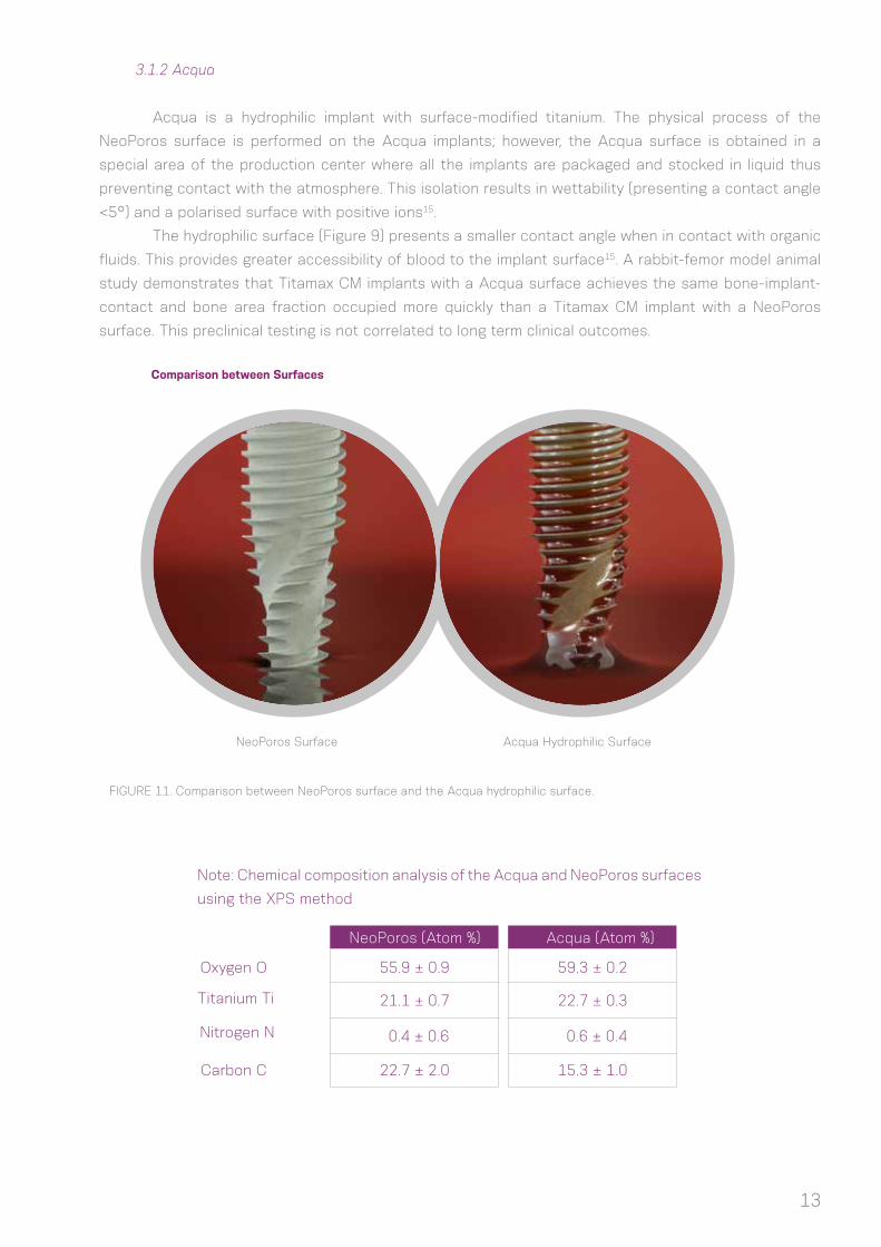
FIGURE 8. Physical manufacturing process for the Neodent® surface treatment.
13
3.1.2 Acqua
Acqua is a hydrophilic implant with surface-modified titanium. The physical process of the
NeoPoros surface is performed on the Acqua implants; however, the Acqua surface is obtained in a
special area of the production center where all the implants are packaged and stocked in liquid thus
preventing contact with the atmosphere. This isolation results in wettability (presenting a contact angle
<5°) and a polarised surface with positive ions15.
The hydrophilic surface (Figure 9) presents a smaller contact angle when in contact with organic
fluids. This provides greater accessibility of blood to the implant surface15. A rabbit-femor model animal
study demonstrates that Titamax CM implants with a Acqua surface achieves the same bone-implant-
contact and bone area fraction occupied more quickly than a Titamax CM implant with a NeoPoros
surface. This preclinical testing is not correlated to long term clinical outcomes.
Comparison between Surfaces
NeoPoros Surface Acqua Hydrophilic Surface
Oxygen O
Titanium Ti
Nitrogen N
Note: Chemical composition analysis of the Acqua and NeoPoros surfaces
using the XPS method
NeoPoros (Atom %) Acqua (Atom %)
Carbon C
55.9 ± 0.9 59.3 ± 0.2
0.4 ± 0.6 0.6 ± 0.4
21.1 ± 0.7 22.7 ± 0.3
22.7 ± 2.0 15.3 ± 1.0
FIGURE 11. Comparison between NeoPoros surface and the Acqua hydrophilic surface.

14
3.2 Implant Options
(1) Available in Acqua surface; (2) Implant with conical central core; (3) Main
screw threads have a square format with a thread pitch of 2.2 mm; (4) Implant with
dual thread for minimal trauma and faster placement19,20; (5) Counterclockwise cutting
chambers distributed throughout the implant body; (6) Lower portion of the screw
thread with cutting edge; (7) Round apex; (8) Indicated for bone types III and IV and
immediate placement of a postextraction implant; (9) Same prosthetic connection for
all implant diameters; (10) The implant should be positioned 1-2 mm below bone level
for best results; (11) Drilling speed: 500 - 800 rpm; (12) Insertion speed: 30 rpm; (13)
Maximum insertion torque: 60 N.cm.
3.2.2 Drive GM™
(1) Available in the Acqua surface; (2) Tapered implant; (3) Compacting
trapezoidal screw threads with a thread pitch from 1.2 to 1.5 mm (depending on the
implant diameter); (4) Implant with dual screw threads for minimal trauma and faster
placement19; (5) Conical apex with low-activity chambers and helicoidal chambers;
(6) Indicated for all bone density types and post-extraction placement; (7) A tapered
contour drill is required if used in bone types I and II; (8) Same prosthetic connection
for all implant diameters; (9) Final pilot drills are highly recommended for bone types I
and II; (10) The implant should be positioned 1-2 mm below bone level for best results19;
(11) Drilling speed: 800-1200 rpm for bone types I and II; (12) Drilling speed: 500-800
rpm for bone types III and IV; (13) Insertion speed: 30 rpm; (14) Maximum insertion
torque: 60 N.cm.
3.2.1 Helix GM™

15
3.2.3 Titamax GM™
(1) Available in the Acqua surface; (2) Implant with parallel walls (cylindrical);
(3) Triangular (or pyramidal) screw threads with a thread pitch of 1.2 mm; (4) Implant
with dual screw thread for minimal trauma and faster placement19; (5) Active cutting
apex with self-tapping chambers; (6) Indicated for bone types I and II and block bone
graft areas; (7) The implant’s cervical diameter is the same as the body; (8) Final pilot
drills are highly recommended as the implant should be positioned 1-2 mm below bone
level for best results19; (9) The use of tap drill is not necessary as the implant itself
cuts the bone during placement; (10) Drilling speed: 800 - 1200 rpm; (11) Insertion
speed: 30 rpm; (12) Maximum insertion torque: 60 Ncm.
TABLE 3. Summary of the implant indication according to bone type (Lekholm and Zarb, 1985).
*Conical contour drill is required
Helix GM™ Acqua
Implant
Bone Density
Bone type I Bone type II Bone type III Bone type IV
Drive GM™ Acqua
* *
- -
--Titamax GM™ Acqua

16
3.3 Options for Screw Threads and Overview of the Format According to Implant Design
HelixTM GM:
*There are variations due to the length and diameter options for the implant.
0.15 - 0.55 mm
0.60 - 0.75 mm

17
Titamax GM™:
Drive GM™:
0.40 - 0.71 mm
0.30 - 0.60 mm
0.55 - 0.80 mm
1.10 mm

All clinical cases and different bone densities. Placement
in bone types III and IV (with the possibility of sub-
instrumentation), I and II with use of a tapered contour drill.
Bone tissue with density type I or II, placement in block graft
area.
18
4.0 INDICATIONS AND CONTRAINDICATIONS
Neodent® implants are manufactured with cold-worked grade 4 titanium to increase the product’s
mechanical resistance. All posts and abutments are made of titanium alloy (TAV). The following table lists the
specific measurements for these items.
For more information on indications and contraindications for each implant, consult the corresponding
instructions for use. The instructions can also be found at ifu.neodent.com.br.
*Minimum width of the alveolar ridge: minimum buccal-lingual width of the alveolar ridge, rounded to 0.5 mm.**Minimum width of the gap: minimum mesiodistal width of a single tooth gap restoration, between adjacent teeth, rounded to 0.5 mm.***HelixTM Ø 6.0 mm is not available in lengths 16 or 18 mm.
Implant General indicationMinimum width of
alveolar ridge*
Minimum width of the
gap**Available lengths
Bone tissue with density III or IV, postextraction placement and in regions grafted with biomaterial.
5.5 mm
5.5 mm
5.5 mm
5.5 mm 8/10/11.5/13/16***/18*** mm
5.5 mm 8/10/11.5/13/16/18 mm
5.5 mm 7/8/9/11/13/15/17 mm
Helix GMTM
Drive GM™
Titamax GM™

19
5.0 PREOPERATIVE PLANNING
5.1 Implant positioning and peri-implant tissue
Positioning of the implant is the key for obtaining the correct positioning of the prosthetic restoration
and is the basis for the surgical plan. Proper communication between the patient, surgeon, restorative doctor
and dental tehnician is essential for achieving the desired prosthetic results.
To establish the correct plan, with proper spatial positioning and design choice (diameter and length)
and the correct number and distribution of implants, the following steps are recommended:
- Perform the wax-up in the patient’s study model.
- Define the edentulous gap to be restored.
- Define the type of superstructure.
- Perform computer-aided tomography and radiography.
The wax-up can be used to make the radiographic and/or surgical guide and the provisional restoration.
Physiological occlusion is essential for the short- and long-term success of the implant. Immediate loading
procedures should not be performed on patients with occlusion problems.
Notes: Prosthetic abutments should always receive axial loads, and the implant’s long axis should be aligned with the cusps of
the opposing teeth. The extreme anatomy of the cusps should be avoided, because it can lead to pathological overload.
The diameter, type, position and number of implants should be decided on an individual basis for each
patient, taking into consideration the anatomy and prosthetic gap. Poorly positioned or angled teeth should
be considered and analyzed. The recommendations in these guidelines should be considered a basic guide
for proper biological healing, adequate restorations and for the patient to have efficient hygiene in that area.
The design of the restoration has a strong effect on occlusion and hygiene and should be considered.
The final response of soft and hard tissue is highly influenced by the position of the abutment;
therefore, three-dimensional positioning of the implant needs to be studied and consists of the following:
• Mesiodistal
• Vestibulolingual
• Cervicoapical

20
5.1.1 Mesiodistal positioning of the implant
The mesiodistally available bone is an important factor in choosing the diameter and number of
implants. The mesiodistal gap is the distance between the implant and the teeth or between implants,
when multiple implants are necessary. The point of reference is the measurement of the largest mesiodistal
width of the implant, usually in the cervical regions. Implants generally require a minimum of adjacent bone
surrounding them of 1.5 mm. The distances listed here are rounded to a minimum of 0.5 mm of bone. However, in preclinical studies, Cone Morse implants placed below bone level present bone and soft tissue
maintenance up to an interimplant distance of 2.0 mm.9
The basic rules are as follows:
Rule 1
Ideally, the distance from the implant to the
adjacent teeth should be at least 1.5 mm
between the largest portion of the implant
and the teeth, in both the mesial and distal
aspects.
Rule 2
Given that the implants require a minimum
adjacent bone of 1.5 mm, the minimum
distance to other implants is 3.0 mm.

21
5.1.1.1 Examples of single teeth gaps
For single tooth restorations, the implant should be placed in the center of the gap. The following
example shows how to follow Rule 1.
For all Neodent® Grand Morse™ implants, the gap size needs to be considered when selecting the
implant diameter. To position an implant within the gap according to Rule 1, the following aspects may be used
as an approximation:
FIGURE 12. The distance between adjacent teeth is approximately 1.0 mm greater at the bone level due to the dental anatomy and the interproximal contact point, when compared with the actual bone width of the gap (2 x 0.5 mm). Therefore, applying Rule 1, the gap must be 2.0 mm wider than the width of the implant.
0.5 mm for both
Distance at the bone level between adjacent teeth

22
D - Diameter of the Implant (mm)
E1 - Tooth-implant distance
(mm)A - Width of the Gap (mm)
B - Distance between the adjacent teeth at the
bone level (mm)
5.5
5.75
6.0
8.0
6.5
6.75
7.0
1.5
9.0
3.5
3.75
4.0
4.3
5.0
6.3
7.0
7.3
8.0
6.0
*Rule 1 applied on both sides of the implant.
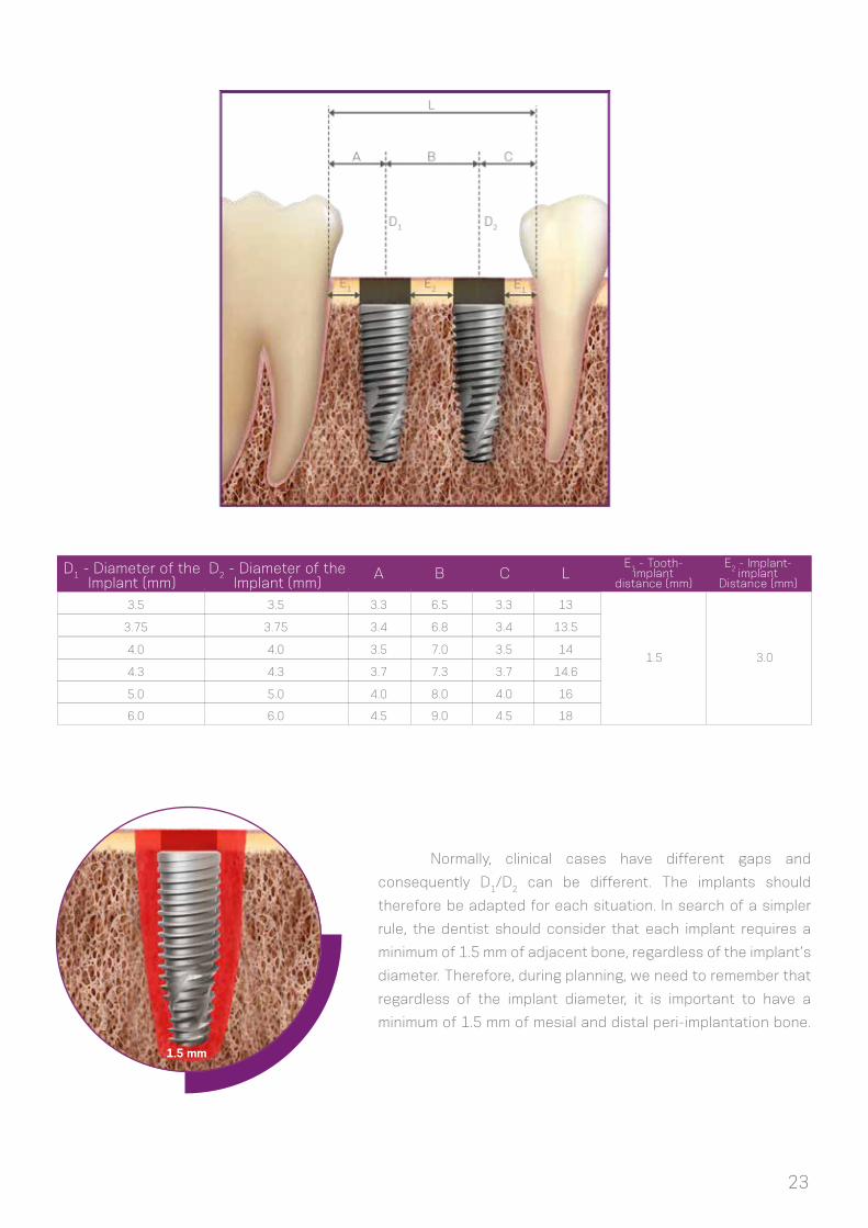
5.1.1.2 Examples of multiple teeth gaps
The examples below show how Rules 1 and 2 are applied to multiple tooth gaps. The measurements
are performed in the bone crest of the tooth adjacent to the center of the implant and between the centers
of the implants. The center of the implant should be considered due to the initial drilling during the osteotomy.
The minimum distance of 3 mm should be followed between the cervical regions of the implants (Rule 2),
which is important for flap closure, to avoid proximity of the abutments and provide adequate space for
maintenance, emergency restoration profile and oral hygiene.
D + 2 mm D + 3 mm*Rule
23
D1 - Diameter of theImplant (mm)
D2 - Diameter of theImplant (mm)
A B C L
3.5
3.75
4.0
4.3
5.0
3.5
3.75
4.0
4.3
5.0
3.3
3.4
3.5
3.7
4.0
6.5
6.8
7.0
7.3
8.0
3.3
3.4
3.5
3.7
4.0
13
13.5
14
14.6
16
Normally, clinical cases have different gaps and
consequently D1/D2 can be different. The implants should
therefore be adapted for each situation. In search of a simpler
rule, the dentist should consider that each implant requires a
minimum of 1.5 mm of adjacent bone, regardless of the implant’s
diameter. Therefore, during planning, we need to remember that
regardless of the implant diameter, it is important to have a
minimum of 1.5 mm of mesial and distal peri-implantation bone.
1.5 mm
E2 - Implant-implant
Distance (mm)
3.0
E1 - Tooth-implant
distance (mm)
1.5
6.0 6.0 4.5 9.0 4.5 18

24
5.1.2 Buccal-lingual implant position
5.1.3 Cervicoapical position of the implant
The buccal and palatal bone plate should be at least 1 mm thick to ensure the stability of the bone
tissue and the condition of the soft tissue. The minimum vestibulolingual width for each implant diameter is
listed in Table 4. Within this limitation, the vestibulolingual position and the long axis of the implant should be
chosen to provide the best possible restorative results. The surgeon also needs to know whether the plan is
to place a screw-retained or cement-retained prosthesis.
Warning: Bone graft techniques are highly advisable in the alveolar ridges in which the buccal bone plate is 1 mm
thick or less or when bone is lacking on one of the sides. These procedures should be conducted only by surgeons with
advanced experience in bone regeneration with grafts.
Neodent® Grand Morse™ implants were
developed for 2-mm positioning below bone level
to optimize the stability of hard and soft tissue
and for better esthetic results of the restorations,
especially in the anterior regions.6,7,8,9,10,12
For situations with uneven ridges, position
the implant at the bone level corresponding to the
most apical bone wall. Depending on the clinical
case, some osteotomy might be required, given that
the abutments have limitations in the transmucosal
height. The implant should be completely covered
with bone or graft with biomaterials to prevent
titanium dehiscence.
FIGURE 13. Example of implant positioned for cement-retained prosthesis (A) and screw-retained prosthesis (B), where there is access to the retaining screw.
(A) (B)

25
5.2 Planning Aids
5.2.1 Space Planning Instrument for assisting in the diagnosis and positioning of implants
When using the 7/9 mm Space Planning Instrument in the patient’s mouth or in the study model, an
initial analysis of the spatial relationships can be performed, in order to select the implant diameter and the
prosthetic reconstruction. The Space Planning Instrument has two ends measuring 7 and 9 mm in diameter,
with a mark exactly in the middle of each end (3.5 and 4.5 mm); this serves as a reference for the surgeon to
position the implant, respecting the rule of a 1.5-mm minimum adjacent peri-implant bone thickness.
The 1.5-mm rule is important for placing the implant based on the position of the teeth, implants and
anatomical structures, such as nerves. The Space Planning Instrument can help with the positioning of an
implant close to the foramen.
FIGURE 14. Diagnostic Space Planning Instrument
for gaps and positioning of implants.
FIGURE 15. Close-up of the 7-mm end of the Space Planning Instrument for
analyzing the gaps. The mark is 3.5 mm from the edge.
FIGURE 16. Using the Space Planning Instrument for the positioning of the osteotomy for implant placement.

26
5.2.2 Direction indicators for orientation of angulation and positioning
FIGURE 17. The lower (2 mm), middle (diameter of the implant) and upper (diameter of the last drill used in the basic osteotomy) parts of the Direction Indicator.
TABLE 4. Options for Colored Direction Indicators. The center part of the direction indicator has the same width as the implants, based on the measurements marked on the upper part.
All Neodent® Direction Indicators have different dimensions for analyzing the amount of bone
surrounding the osteotomy. All indicators have the following parts: (1) lower, (2) middle and (3) upper.
The lower part of all Direction Indicators are 2.0 mm in diameter, to be adjusted after the initial
osteotomy. The middle part of the Direction Indicator has the diameter of the respective implant. All diameters
are color coded and are listed in Table 4.
Lower UpperMiddle
Direction Indicators Middle Upper
3.5
4.3
3.75
5.0
4.0
2.8
3.6
3.0
4.3
3.3
Diameter

27
The upper part of each direction indicator has the same diameter as the last drill used before the
placement of the implant, according to the Neodent® osteotomy protocols. The positioned Direction Indicator
allows the surgeon to check the adjacent bone, as illustrated below.
There are also angle measurement guides that help the surgeon assess the angulation of abutments
before the implant placement. These measurement guides are available in two angles (17˚ and 30˚) and are
inserted in the 2.0-mm osteotomy.
FIGURE 18. Direction Indicator inserted after the initial drilling and fitted inside the osteotomy according to the drill protocol. The indicator helps analyze the remaining adjacent bone when positioned.
FIGURE 19. Angle measurement guides for selecting abutments.
3.753.0

28
FIGURE 20. Titanium tweezers calibrated in
millimeters.
5.2.3 Surgical drill guide
A customized surgical guide produced by the dental laboratory facilitates the preparation of the
implant bed, enabling the precise use of cutting instruments. The basis for the manufacture of this guide
should be the desired prosthetic results.
The study models can be drilled with 2.0-mm drills in the position of the implant, and guides for the
2.0-mm diameter pins are fitted on the perforations. Guides manufactured with wax or vacuum-formed are
built with the pins positioned in their interior. Once the surgical guide has been made aseptic, it can be used
during surgery, and its guides will direct the initial drilling of the surgical procedure.
FIGURE 21. 2.0-mm diameter guides and pins to be fitted in the patient’s study model.
2.02.0
2.0
Notes: The Titanium Tweezers have a ruler at the apex.

29
6.0 SURGICAL PROCEDURES
6.1 Implant bed preparation
The diameter, position and number of implants should be selected based on the anatomy and spatial
circumstances. The measurements should be performed according to the basic guidelines.
The basic preparation of the implant bed involves preparing the ridge and perforating it with a twist
drill under irrigation, for which the diameter and design (if cylindrical or conical) of the selected implant will
determine the instruments to be used.
The refined implant bed preparation involves the instruments that conform to the emergence profile
and the bone. For this, the implant type and bone density determine the instruments to be used.
InstrumentsSteps
1. Basic implant bed preparation
Preparation of the ridge
Twist drilling
Initial Drill
2.0-mm twist drill; Direction Indicator; Depth Gauge with millimeter markings
Drill format is defined according to the implant design, and the sequence and diameter defined by its width
Tapered Contour Drill
2. Refined implant bed preparation
Conical or cylindrical drills and bone profile drills
For Helix GMTM in bone types I and II
Note: The Titamax GM™, Helix GM™ and Drive GM™ implants can be placed using the same surgical kit, given that Helix GM™ and
Drive GM™ have conical drills for implant bed preparation and that Titamax GM™ also features specific drills.
6.1.1. Basic implant bed preparation
After opening the flap and exposing the bone tissue, the preparation of the alveolar ridge begins.
Once the implant’s position has been established with the aid of surgical guides, the cervical cortical layer
is drilled with the Initial Drill (step 1), and the spatial positioning of the implant is checked visually with the
direction indicator. The indicated number of rotations per minute (rpm) for drilling is based essentially on bone
density, whereby 800-1200 rpm will be applied in bone types I and II, and 500-800 rpm in bone types III and IV.
Subsequently, the 2.0-mm twist drill is used to establish the desired height for the selected implant, always
keeping in mind that the placement of the Grand Morse™ implant is 1-2 mm below bone level. Consequently,
a subsequent drill is employed to prepare the osteotomy, following the sequence based on the implant type
and diameter, as chosen in the preoperative plan. All drills are fitted to the contra-angle handpiece according
to ISO 1797-1 – Dentistry – Shanks for rotary instruments.

30
Step 1 – Preparing the site of the implant and initial drilling
with the Initial Drill
Carefully reduce and regularize the bone surface before
marking the position of the implant with the initial drill.
Insert the initial drill to approximately 5-7 mm with a drill
speed consistent with the bone density.
Note: Bone reduction/preparation should be considered in the preoperative
plan, because it affects the choice of implant diameter and length.
Step 3 – Twist Drill 2.0
Use the 2.0-mm twist drill to reach the planned drilling
length. Use of the depth gauge is recommended for
controlling the depth.
Note: 1 – Periapical radiography is recommended at this point to check
for available vertical bone or to verify the long axis of the drilling in relation
to the adjacent roots, for example. The Direction Indicator should be
completely inserted into the instrumented area, allowing for visualization
of the entry of the drilling in relation to the anatomical structures.
Step 2 – Checking the long axis of the implant
After using the initial drill, check the long axis of the
implant using the direction indicator. The implant diameters
and measurements of adjacent bone can be checked as
described in 3.2.2.
2 – The 2.0-mm Neodent® twist drill has an active apex that can be
used as an initial drill. For flat bony ridges, this drill can replace the
initial drill.

31
Note: Periapical radiography is recommended after the use of tapered drills to check for available bone or to verify the long axis
of the drilling in relation to the adjacent roots. A radiographic positioner should be inserted in the osteotomy.
6.1.1.1 Implant bed preparation for Helix GMTM tapered implants
103.418 103.427103.405 103.422103.414 103.411103.420 103.416103.399 103.423103.415 103.408103.419 103.417103.402 103.421103.425103.170
Initial Ø 5.0+Ø 4.3+Ø 4.0+Ø 3.75+Ø 3.5+ Ø 5.0Ø 4.3Ø 4.0Ø 3.75Ø 3.5Ø 2.0
Ø 3.5
Ø 3.5
Ø 3.75
Ø 3.75
Ø 4.0
Ø 4.0
Ø 4.3
Ø 4.3
Ø 5.0
Ø 5.0
Ø 4.3/5.0 Ø 6.0Ø 3.6/4.3Ø 3.3/4.0Ø 3.0/3.75Ø 2.8/3.5
Bone types I and II
Optional
Optional
Optional
Optional
Optional
Optional Optional
Optional
Optional
Optional
Optional
Optional
Optional
Optional
Optional
Ø 6.0 Optional
For bone types III and IV

32
Helix GMTM - For bone types I and II
*The sequence can be started directly with the 2.0 drill if the bone bed is flat.
Instruments for basic bone implant preparation Diameters (mm)
Step
1 – Prepare the
implant bed and
initial drilling
2 – Check the long
axis of the implant
3-Taperd Drill 2.0*
4-Tapered 3.5
103.170
103.425
103.419
103.420
103.421
103.422
103.423
103.408
103.411
128.022
128.023
129.013
129.014
103.399
128.019
129.009
128.020
103.402
103.405
103.414
103.415
103.416
103.417
103.418
128.021
128.019
Initial Drill
Tapered Drill 3.5
Tapered Drill 4.3
Tapered Drill 5.0
Tapered Drill 3.75
Tapered Drill 4.0
Direction indicator 2.8/3.5
Direction indicator3.6/4.3
Direction indicator 4.3/5.0
Direction indicator 3.0/3.75
Direction indicator 3.3/4.0
Tapered X-Ray Positioner 3.5
Tapered X-Ray Positioner 4.3
Tapered X-Ray Positioner 5.0
Pilot Drill 2.8/3.5
Pilot Drill 3.0/3.75
Direction indicator 2.8/3.5
1200
1200
1200
1200
1200
1200
1200
1200
1200
1200
1200
1200
1200
1200
1200
1200
1200
6-Tapered 3.75
7-Pilot Drill
3.0/3.75
Tapered Contour Drill 3.5
Tapered Contour Drill 4.3
Tapered Contour Drill 5.0
Tapered ContourDrill 3.75
Tapered Contour Drill 4.0
Tapered Drill 2.0
8-Tapered 4.0
10-Tapered 4.3
12-Tapered 5.0
5-Pilot Drill
2.8/3.5
9-Pilot Drill3.3/4.0
11-Pilot Drill 3.6/4.3
13-Pilot Drill 4.3/5.0
Pilot Drill 3.3/4.0
Pilot Drill 3.6/4.3
Pilot Drill 4.3/5.0
Code Product Max. RPM Image
-
-
-
-
-
-
-
-
-
Ø 4.0Ø 3.5 Ø 4.3Ø 3.75 Ø 5.0
-
-
-
-
-
-
-
-
-
-
-
-
-
-
-
-
-
-
-
-
-
-
-
-
-
Optional Optional
Optional Optional Optional Optional Optional
Optional
Optional
Optional

Ø 5.0
33
Helix GMTM - For bone types III and IV
*The sequence can be started directly with the 2.0 drill if the bone bed is flat.
Instruments for basic bone implant preparation Diameters (mm)
Step
1-Prepare the
implant bed and
initial drilling*
2-Check the long
axis of the implant
3-Tapered Drill 2.0*
4-Tapered 3.5
103.170
103.425
103.419
103.420
103.421
103.422
103.423
103.408
103.411
128.022
128.023
129.013
129.014
103.399
128.019
129.009
128.020
103.402
103.405
103.414
103.415
103.416
108.417
103.418
103.427
128.021
128.019
Initial Drill
Tapered Drill 3.5
Tapered Drill 4.3
Tapered Drill 5.0
Tapered Drill 3.75
Tapered Drill 4.0
Direction indicator 2.8/3.5
Direction indicator 3.6/4.3
Direction indicator 4.3/5.0
Direction indicator 3.0/3.75
Direction indicator 3.3/4.0
Tapered X-Ray Positioner 3.5
Tapered X-RayPositioner 4.3
Tapered X-Ray Positioner 5.0
Pilot Drill 2.8/3.5
Pilot Drill 3.0/3.75
Direction indicator 2.8/3.5
800
800
800
800
800
800
800
800
800
800
800
800
800
800
800
800
800
800
6-Tapered 3.75
7-Pilot Drill 3.0/3.75
Tapered Contour Drill 3.5
Tapered Contour Drill 4.3
Tapered Contour Drill 5.0
Tapered ContourDrill 3.75
Tapered Contour Drill 4.0
Tapered Drill 2.0
8-Tapered 4.0
10-Tapered 4.3
12-Tapered 5.0
5-Pilot Drill
2.8/3.5
9-Pilot Drill3.3/4.0
11-Pilot Drill 3.6/4.3
13-Pilot Drill4.3/5.0
14-Tapered 6.0
Pilot Drill 3.3/4.0
Drill Pilot 3.6/4.3
Pilot Drill 4.3/5.0
Tapered Drill 6.0
Code Product Max. RPM Image
-
-
-
-
-
-
-
-
-
Ø 4.0Ø 3.5 Ø 4.3Ø 3.75 Ø 5.0 Ø 6.0
--
-
-
-
--
-
-
-
-
-
-
-
-
- -
- -
- -
- -
- -
- -
- -
- -
-
-
-
-
-
- -
- -
- -
Optional Optional Optional
Optional OptionalOptional Optional Optional Optional
Optional
Optional
Optional
Optional
-
-

34
6.1.1.2 Implant bed preparation for Drive GM™ tapered implants
103.408 103.411103.399 103.418103.414 103.417103.425103.170
Initial Ø 5.0Ø 3.6/4.3Ø 3.5Ø 2.0 Ø 4.3/5.0Ø 4.3Ø 2.8/3.5
For bone types III and IV
Optional
Optional
Optional
Ø 3.5 mm
Ø 4.3 mm
Ø 5.0 mm
Drive GM™
*The sequence can be started directly with the 2.0 drill if the bone bed is flat.
Instruments for basic bone implant preparation Diameters (mm)
Step
1-Prepare the
implant bed and
initial drilling*
2-Check the long
axis of the implant
3-Tapered Drill 2.0*
4-Tapered Drill 3.5
103.170
103.425
103.399
103.408
103.411
129.009
129.013
129.014
128.019
128.022
128.023
128.019
Initial Drill
Tapered Drill 2.0
Taperedl Drill 3.5
Tapered Drill 4.3
Tapered Drill 5.0
Tapered X-Ray Positioner 3.5
Tapered X-RayPositioner 4.3
Tapered X-RayPositioner 5.0
Direction indicator 2.8/3.5
Direction indicator 3.6/4.3
Direction indicator 4.3/5.0
Direction
indicator 2.8/3.5
800
800
800
800
800
-
-
-
-
-
-
-
6-Tapered Drill 4.3
8-Tapered Drill 5.0
Code Product Max. RPM Image Ø 3.5 Ø 4.3 Ø 5.0
- -
-
103.418
103.417
103.414
800
800
800
9-Pilot Drill 4.3/5.0
7-Pilot Drill 3.6/4.3
5-Pilot Drill2.8/3.5
Pilot Drill 4.3/5.0
Pilot Drill 3.6/4.3
Pilot Drill 2.8/3.5 Optional
Optional
Optional

35
6.1.1.3 Implant bed preparation for Titamax GM™ cylindrical implants
Ø 3.5 mm
Ø 3.75 mm
Ø 4.0 mm
Ø 5.0 mm
103.164 103.416103.166 103.168103.213 103.415 103.418103.163 103.414 103.167103.162103.170
Initial Ø 3.3 Ø 4.3Ø 2.8/3.5 Ø 3.8Ø 2/3Ø 2.0 Ø 3.0/3.75 Ø 4.3/5.0Ø 3.0 Ø 3.3/4.0Ø 2.8
For bone types I and II
Titamax GM™
*The sequence can be started directly with the 2.0 drill if the bone bed is flat.
Instruments for basic bone implant preparation Diameters (mm)
Step
1-Prepare the
implant bed and
initial drilling*
2-Check the long
axis of the implant
3-Twist Drill 2.0*
4-Twist Drill
2.8
103.170
103.162
103.163
103.164
128.021
103.418
128.023
128.019
103.414
103.415
128.020
103.416
103.213
103.106
103.168
103.167
128.019
Initial Drill
Direction indicator 2.8/3.5
Pilot Drill 3.5
Direction indicator 4.3/5.0
Pilot Drill4.3/5.0
Pilot Drill 2/3
Pilot Drill 3.3/4.0
Direction indicator 3.3/4.0
Pilot Drill 3.0/3.75
Direction indicator 3.0/3.75
Direction
indicator 2.8/3.5
1200
1200
1200
1200
1200
1200
1200
300
1200
1200
300
6-Twist Drill
3.0
7-Twist Drill
3.3
Twist Drill
3.3
Twist Drill3.0
10-Twist Drill
4.3
Twist Drill4.3
Twist Drill
2.8
Twist Drill3.8
Twist Drill
2.0
8-Pilot Drill
3.3/4.0
9-Twist Drill
3.8
11-Pilot Drill 4.3/5.0
5-Pilot Drill 2/3
Code Product Max. RPM Image
-
-
-
-
-
-
Ø 4.0Ø 3.5 Ø 5.0Ø 3.75
- -
-
-
-
-
-
- - -
- - -

36
1: All tapered drills have similar marks related to each implant length, regardless of diameter.
2: All drills are also available in the short version, and some are available in the long version.
3: Due to their function, tapered drills are at most 0.5 mm longer than the implant. This additional length should
be considered before the surgical procedure.
4: The implants in the image are 13 mm long.
13
16
11.510
8
18
1: All twist drills have similar marks related to each length of GM Titamax implants, regardless of diameter.
2: The implant in the image is 13 mm long.
NOTE: Length comparison between drills and implants.

37
Note: The Tapered Contour Drills have the “+” symbol to indicate that they are supplementary instruments.
6.1.2 Details on special implant bed preparation
6.1.2.1 Tapered Contour Drill
The special implant bed preparation considers the use (1) of the pilot drill and (2) the tapered contour
drill when necessary. The instruments depend on the implant type and diameter and bone type. Osteotomies
in bone types I and II need final pilot drills for the final positioning of the implant. Tapered contour drills are
required only for the use of the HelixTM GM implant in regions of high bone density.
Tapered Contour Drills are especially indicated as supplementary instruments for osteotomy when
implanting HelixTM GM implants in bone types I and II. There are different tapered contour drills selected
according to the implant diameter. The drills are used only on bone types I and II, connected to the contra-
angle handpiece, with a rotation speed of approximately 800-1200 rpm. This step is intended to keep the
insertion torque at a desirable level in bone types I and II.

38
Step 2- GM Pilot Drill
Perform the osteotomy with the conical drills. Depending
on the level of the final positioning of the implant (bone
level, 1 or 2 mm below bone level), use the pilot drill for
the final positioning of the implant.
Step 1 - Drilling in dense bone
Use the tapered contour drill across the entire
length of the planned implant.
6.1.2.3 Example of special implant bed preparation
The following is an example of the special preparation of the implant bed for a Helix GMTM implant (Ø 4.3
mm and 13 mm long) in bone type I or II, making the use of contour and pilot drills necessary. The steps described
follow the basic preparation of the implant bed (6.1.1.1).
FIGURE 22: Pilot drill for the refined implant bed preparation for the implant. The drill helps in the cervical positioning of the implant in areas of greater bone density: if at bone level, 1, 2 or 3 mm below bone level. Pilot drills are optional for Drive GM™ implants.
bone level(GM implants)
1 mm below bone level
2 mm below bone level
3 mm below bone level
6.1.2.2 Pilot Drill
Pilot drills are employed to prepare the implant
bed to widen the diameter of one twist drill to another, in
the basic instrumentation procedure. For the special bone
preparation, pilot drills help position the platform of the
Grand Morse™ implants according to the bone bed, if there
is a denser cortical bone bed of 1, 2 or 3 mm below bone
level. Pilot drills are generally used in this manner in bone
types I and II and are indicated as optional in bone types
III and IV. For Drive GM™ implants, the use of this drill is
optional. The maximum rotation speed used for these drills
is 800 rpm for bone types III and IV and 1200 rpm for bone
types I and II.
bone level(WS implants)

39
*Optional.** Only for bone types I and II.
Note: Surgical drills have a life cycle of up to 30 perforations for bone quality I, II, III and IV, provided the conditions of use recommended by Neodent® are respected. Regardless of the number of times the instruments are used, the practitioner should always assess the condition of the instruments after each use.
Note: Bone quality classification according to Lekholm and Zarb (1985).
The following table summarizes the use of Pilot and Tapered Contour drills for the special
preparation of the implant bed.
Instruments for the special bone implant preparation Implants
CodeTitamax
GMTM
HelixGMTM
DriveGMTMProduct Max. RPM Image
Pilot Drill
2.8/3.5
Pilot Drill
3.6/4.3
Tapered Contour
Drill 3.5
Pilot Drill
3.0/3.75
Pilot Drill
4.3/5.0
Tapered Contour
Drill 3.75
Tapered Contour
Drill 4.3
Pilot Drill
3.3/4.0
Tapered Contour
Drill 4.0
Tapered Contour
Drill 5.0
103.414
103.417
103.419
103.415
103.418
103.420
103.422
103.416
103.421
103.423
1200 Ø 3.5 Ø 3.5** Ø 3.5*
Ø 4.0 Ø 4.0**
Ø 5.0
-
-
-
-
-
-
-
-
-
-
-
-
Ø 5.0** Ø 5.0*
Ø 3.75**
Ø 4.3**
Ø 3.75 Ø 3.75**
Ø 4.3 Ø 4.3** Ø 4.3*
Ø 3.5**
Ø 4.0**
Ø 5.0**
1200
1200
1200
1200
1200
1200
1200
1200
1200

40
6.1.2.4 Options for drills
Neodent® drills are available in short (31 mm), standard (35 mm) or long (43 mm) formats to cater for
limitations in mouth opening or for use between two teeth. In case of necessity a Drill Extension can also be
used.
FIGURE 23. Length options for Grand Morse™ drills (31 mm, 35 mm and 43 mm).
6.2 Neodent® Implant Packaging
Neodent® packaging has been specially updated for easy
handling and safe surgical procedures, providing practicality from
implant stocking to the capture and transport and implant bed.
The implant’s features, such as type, diameter and length, are
readily identifiable on the outside of the packaging.
Three self-adhesive labels are provided for recording in
the patient’s medical records and for reporting to the prosthesis
team. They also allows traceability for all articles.
FIGURE 24. Drills fit inside the Neodent® Drill Extension.
41
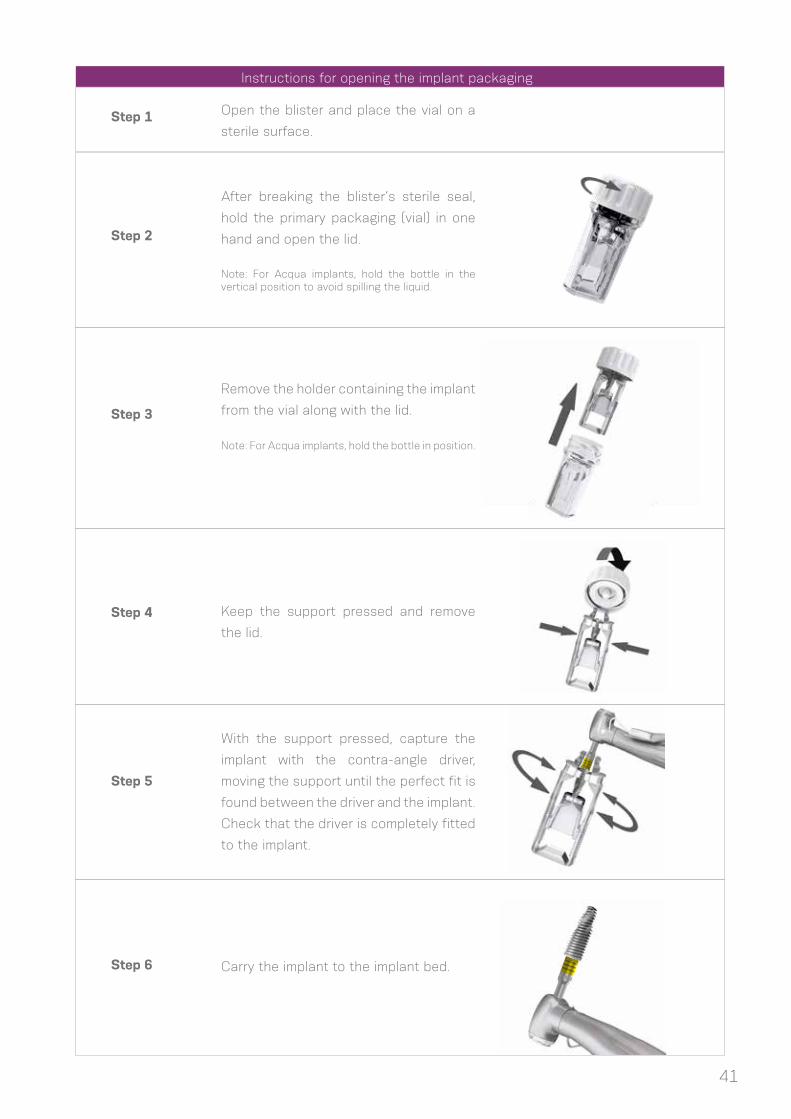
Instructions for opening the implant packaging
Step 1
Step 2
Step 3
Step 5
Step 4
Step 6
Open the blister and place the vial on a
sterile surface.
After breaking the blister’s sterile seal,
hold the primary packaging (vial) in one
hand and open the lid.
Note: For Acqua implants, hold the bottle in the vertical position to avoid spilling the liquid.
Remove the holder containing the implant
from the vial along with the lid.
Note: For Acqua implants, hold the bottle in position.
With the support pressed, capture the
implant with the contra-angle driver,
moving the support until the perfect fit is
found between the driver and the implant.
Check that the driver is completely fitted
to the implant.
Keep the support pressed and remove
the lid.
Carry the implant to the implant bed.

42
6.3 Placing of the Grand Morse™ Implant
Neodent® Grand Morse™ implants were developed to begin placement with the contra-angle
handpiece or manually, and completed with the Torque-indicating Wrench. The maximum recommended
rotation speed for the surgical motors is 30 rpm, with a torque of 35 N.cm.
The following instructions show the steps for handling the Neodent® Grand Morse™ implant for
placement with the contra-angle handpiece.
6.3.1 Placing of the implant with the contra-angle handpiece
Step 1 - Adapt contra-angle implant driver
Hold the implant through the blister, and attach
the contra-angle implant driver to the Grand
Morse™ implant. All drivers for the contra-
angle handpiece have metal tweezers in the
active apex to keep the implant stable during
transport. The torque wrench drivers do not
have tweezers to keep the implants in position
for transport.
Step 2 – Place the implant with the contra-
angle handpiece in the implant bed
Place the implant to its final position with a
maximum torque of 35 N.cm and speed of 30
rpm, clockwise.
Warning: Corrections in the vertical position by
means of reverse rotations during surgery can
lead to reduced primary or mechanical stability.

43
Step 3 – Final positioning of the implant
Neodent® Grand Morse™ implants have an internal hexagon index known as Exact. Ensure
that the final position of the implant shows one of the prosthetic orientation marks facing the buccal
aspect.
The implant drivers have six marks that line up with the six sides of the GM Exact. Position
one of the driver marks towards the buccal aspect to ensure the optimal positioning of the indexed
abutments with GM Exact.
AA
Note 1: There are 3 similar markings at 1-mm intervals in the Drivers for the Contra-angle handpiece and Torque Wrench.
These markings guide the depth of the final positioning of the implant in the following way: first stripe for 1 mm below bone
level, second for 2 mm and third for 3 mm. Each full turn of the implant results in: (a) 2.2 mm for the Drive implants; (b) 1.4
mm on average for the HelixTM implants; and (c) 1.2 mm for the Titamax implants.
Note 2: An important difference between the contra-angle driver and the torque wrench driver is that the contra-angle
handpiece driver features metal tweezers in the apex to keep the implant in position. Torque Wrench drivers are therefore
not indicated for transporting the implant from the blister to the patient’s mouth.
GM Driver for Contra-Angle Handpiece
GM Driver for Torque WrenchLong Short
bone level1 mm below bone level
2 mm below bone level
3 mm below bone level

44
The implant placement sequence can also be achieved manually, using the Manual Implant
Driver - Contra-angle instead of the contra-angle handpiece.
6.3.2 Manual placement of the implant
FIGURE 25. All instruments for contra-angle handpieces can be fitted to the Manual Implant Driver - Contra-angle.
Remove the Grand Morse™ contra-angle handpiece driver from the implant, and fit the torque
wrench driver for the final positioning of the implant and torque measurement. There are two torque
wrench driver options: short and long. First, use the fingers to fit the driver to the interior of the implants
and then hitch the torque wrench onto the driver. The torque wrench drivers should not be used to
transport the implant from one place to another because the product can fall out. Apply torque until
the implant reaches its final position. All torque wrenches show torque levels. A value above 60 N.cm
is contraindicated.
Warning: Corrections in the vertical position by means of reverse rotations during surgery can lead to reduced primary or mechanical stability.
6.3.3 Completing the positioning of the implant with the Torque Wrench
Manual Implant Driver - Contra- angle
GM Driver forContra-angle Handpiece
GM Long Torque Wrench Driver
GM Short Torque Wrench Driver

45
Neodent® Torque Wrenches are demountable
because they need to be cleaned internally before the
sterilization process in the autoclave. The thin rod is used
to measure and indicate the torque value when handled.
Note: Implants can be placed with these drivers fitted to a GM Torque Wrench Driver. However, this does not allow the surgeon to apply the final torque for the implant and thus is only indicated for the initial positioning of the implant with the Handle Implant Driver.
For submucosal healing (under a closed mucoperiosteal
flap), the use of the GM Cover Screw is indicated. A second surgical
procedure is necessary to reveal the implant and insert the desired
abutment.
The Neodent® system has two cover screws, which are sold
separately and sterile packed, at the implant level and 2 mm (above
the implant shoulder) for positioning below bone level.
GM Cover Screw
2-mm GM Cover Screw
6.3.4 Torque Wrench
6.4 Handling soft tissue
After implant placement, the implant is covered with a cover screw or healing abutment to protect
it. The surgeon may choose between submucosal or transmucosal healing and has all available options for
handling soft tissue by means of a secondary healing component kit.
6.4.1 Two-step/submucosal healing

46
Step 1 – Inserting the cover screw
Ensure that the internal configuration is clean and free of
blood residue. Capture the GM Cover Screw with the Neo
Manual Screwdriver. A perfect fit ensures the transport for
the implant, and manually tighten the screw.
Step 2 – Close the incision
Adjust the edges of the flap and suture with tension-free
stitches.

47
Step 4 – Reopening and removal of the GM Cover Screw
Second surgery – After the bone regeneration period for each type of implant and
bone, locate the implant with the help of the surgical guide, X-rays or measurements,
and, with the desired technique, make an incision to reach the implant, and remove
the GM Cover Screw with the Neo Manual Screwdriver.
Step 3 – Regeneration period
Remove the suture after approximately 7 days or once it has lost its function and
wait for the bone regeneration phase.
Note: Be careful when using the 2-mm GM cover screw because it can become exposed when placed in implants at the bone level and with a thin mucosal thickness. Exposure of this screw allows mechanical contact with mobile prostheses and results in failure in the implantation.

48
Step 5 – Insertion of healing abutment
Irrigate the implant’s exposed internal connection with sterile
saline solution, insert the healing abutment (or an abutment,
if applicable). Adjust the soft tissue and suture around the
healing abutment. More information on healing abutments
can be found in 6.5 (page 51).
Step 6 – Close the wound
Adjust the soft tissue and suture around the healing
abutment.

49
A variety of healing abutments and abutments are available for the Neodent® Grand Morse™ system,
to shape the soft tissue during the transmucosal healing after placing the implant. The abutments can be
used provisionally (to be replaced in the final restoration phase), or a final abutment can be used along
with a provisional restoration. This phase can be defined as a one-step operation (if the healing abutment
is chosen after the surgical procedure) or immediate loading (if a definitive abutment is selected).
The implant’s final placement torque determines the protocol. Correct and physiological occlusion
is also a determinant in the decision. Patients deprived of a balanced occlusion are not good candidates
for the immediate loading protocol. Table 5 lists the criteria to be observed for the use of the immediate
loading protocol.
6.4.2 Transmucosal healing: one-step or immediate loading
TABLE 5: Immediate loading protocol according to torque level.
Torque (Ncm) Healing protocol General characteristics
≥ 32 to ≤ 60 NcmImmediate loading or selection of
abutment
- Lateral mechanical load on provisional
crowns is contraindicated.
- Periodontally compromised patients
should have their condition controlled
prior to treatment, especially when
a component is exposed to the oral
environment.
- Patients should present a balanced
or physiological occlusion.

50
6.4.2.1 Transmucosal healing: one-step
Step 1 – Insertion of healing abutment after implant
placement
Ensure that the internal configuration is clean and free of
blood. Insert the healing abutment manually with the Neo
Manual Screwdriver.
Step 2 – Close the wound
Adjust the soft tissue to the component, and suture with
tension-free sutures.

51
6.5 Overview of the healing abutments
The Neodent® system has a variety of healing abutments, with various diameters and transmucosal
heights corresponding to the definitive abutment. Choosing the correct healing abutment is therefore extremely
important to ensure proper healing of soft tissue, with controlled pressure and respect for biological distances.
Below are the various formats of Grand Morse™ healing abutments to be adapted to the surgeon’s
needs:
Transm
uco
sal h
eig
ht
Ø 3.3 Ø 4.5
0.8 mm 0.8 mm
Transmucosal height of 0.8
- 5.5 mm
Healing Abutments
Ø 3.3 or 4.5
1.5 mm 1.5 mm
2.5 mm 2.5 mm
3.5 mm 3.5 mm
4.5 mm 4.5 mm
5.5 mm 5.5 mm
3.5 mm4.5 mm
5.5 mm6.5 mm
1.5 mm2.5 mm
0.8 mm
GM Height Measurer
To select the correct prosthetic abutment and
check the thickness of the remaining mucosa, there is the
Grand Morse™ Height Measurer, which can be fitted to the
implants and serves as a reference for selecting the most
suitable abutment.
The height of the abutments varies from 0.8 to 5.5 mm and should be chosen based on the gingival
height. Given that the healing abutment’s internal design is identical to that of the definitive abutment, if the
height of the chosen healing abutment is very high, the soft tissue will heal this way as well. If the height of the
chosen definitive abutment is not compatible (lower, for example), it will exert great pressure on the soft tissue,
and the patient will complain of compression pain. It is therefore advisable to choose an abutment with the
same transmucosal width and height as the healing abutment. If the definitive abutment needs to be replaced,
the patient should be anesthetized, and the tissue should be given time to readapt.
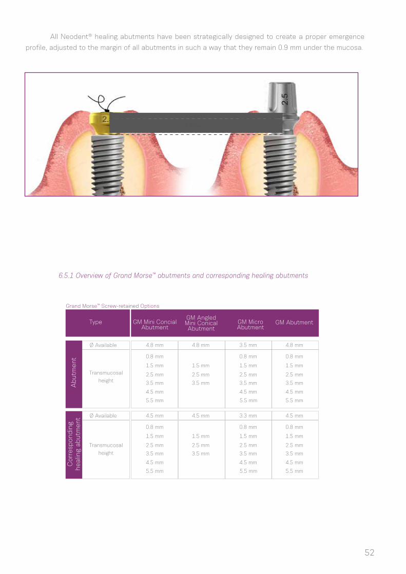
6.5.1 Overview of Grand Morse™ abutments and corresponding healing abutments
Ab
utm
ent
Corr
esp
ond
ing
healin
g ab
utm
ent
Type GM Mini Concial Abutment
GM Abutment
4.8 mm
4.5 mm
4.8 mm
4.5 mm
3.5 mm
3.3 mm
4.8 mm
4.5 mm
0.8 mm
0.8 mm
0.8 mm
0.8 mm
0.8 mm
0.8 mm
1.5 mm
1.5 mm
1.5 mm
1.5 mm
1.5 mm
1.5 mm
1.5 mm
1.5 mm
2.5 mm
2.5 mm
2.5 mm
2.5 mm
2.5 mm
2.5 mm
2.5 mm
2.5 mm
3.5 mm
3.5 mm
3.5 mm
3.5 mm
3.5 mm
3.5 mm
3.5 mm
3.5 mm
4.5 mm
4.5 mm
4.5 mm
4.5 mm
4.5 mm
4.5 mm
5.5 mm
5.5 mm
5.5 mm
5.5 mm
Ø Available
Grand Morse™ Screw-retained Options
Ø Available
Transmucosal
height
Transmucosal
height
All Neodent® healing abutments have been strategically designed to create a proper emergence
profile, adjusted to the margin of all abutments in such a way that they remain 0.9 mm under the mucosa.
GM Angled Mini Conical Abutment
GM Micro Abutment
5.5 mm
5.5 mm
1.0 mm
2.5 mm
52

53
The Grand Morse™ line also features customizable healing abutments. They are produced in titanium,
with a customizable portion made of Peek. The available diameters and transmucosal heights are presented
below. It is also important to notice the height of the parallel portion, which is of 1.5 mm for all options, with
the exception of the 7.0X5.5 mm (with a 2.5 mm high parallel portion) and the 7.0X6.5 mm (with a 3.5 mm
high parallel portion). In all cases, there is the possibility of customizing the upper and lateral portions of the
product. A minimum thickness of 0.5 mm is recommended to be maintained between the screw and the lateral
and upper portions.
Transm
uco
sal h
eig
ht
Ø 5.5 Ø 7.0
1.5 mm 2.5 mm
Transmucosal height of 1.5
- 6.5 mm
Customizable
Healing Abutments
Ø 5.5 or 7.0
2.5 mm 3.5 mm
3.5 mm 4.5 mm
4.5 mm 5.5 mm*
5.5 mm 6.5 mm**
Parallel portion height of 1.5,
2.5 or 3.5 mm
Ab
utm
ent
Corr
esp
ond
ing
healin
g ab
utm
ent
Type
Ø Available
Grand Morse™ Cement-retained Options
Ø Available
Transmucosal
height
Transmucosal
height
GM Universal Abutment (straight)
GM Universal Abutmen(straight)
3.3 mm
3.3 mm
0.8 mm
0.8 mm
1.5 mm
1.5 mm
2.5 mm
2.5 mm
3.5 mm
3.5 mm
4.5 mm
4.5 mm
5.5 mm
5.5 mm
4.5 mm
4.5 mm
0.8 mm
0.8 mm
1.5 mm
1.5 mm
2.5 mm
2.5 mm
3.5 mm
3.5 mm
4.5 mm
4.5 mm
5.5 mm
5.5 mm
Note: GM angled Universal abutments are only available with transmucosal heights of 1.5, 2.5 and 3.5 mm.
6.5.2 Grand Morse™ Customizable Healing Abutments
*parallel portion of 2.5 mm
**parallel portion of 3.5 mm

7.0 HEALING PHASE
The healing protocol depends on:
(1) The implant’s final placement torque or primary stability, as measured with the Torque-indicating
Ratchet Wrench.
(2) The bone type.
More time is needed when low torque values are reached. Immediate loading procedures may also
be applied in cases of minimum placement torque of 32 Ncm.
Once this stage has been reached, the definitive prosthetic abutment should be chosen for the
final restoration. This step can be conducted in the healed mucosa (submucosal healing, conventional
protocol) or during surgery for protocols such as one-step/transmucosal healing or immediate loading.
To help with the selection of abutments, Neodent® offers the GM Height Measurer, which can also
be sterilized and visualized in X-rays.
The following features should be considered:
a. Single tooth or multiple tooth restoration
b. Screw-retained or cement-retained restoration
c. Interocclusal gap, height and width
d. Gingival height (transmucosal height)
e. Biological distance (distance from abutment platform to bone crest)
f. Whether the implant angulation needs to be corrected for the abutment or whether adjacent
abutments are parallel.
8.0 GENERAL PROSTHETIC GUIDELINES
The GM Height Measurer helps determine the gingival height.
The positioning below bone level of implants results in a certain amount of bone over their cervical
region. This tissue can interfere with abutments fitted on the implant. For these situations, Neodent®
provides a GM Bone Profile Drill.
54

Neodent® Kits are available in cassettes to help keep the instruments organized and sterile. The
cassette is manufactured with a heat-resistant polymer and is indicated for frequent sterilization in an
autoclave.
The New Grand Morse™ Surgical Kit is intuitive and functional and features exclusive instruments for
placing the new Helix GMTM, Drive GM™ and Titamax GM™ implants.
Neodent® kits reusable and supplied non-sterile, packed individually. This product must be
correctly sanitized and sterilized before each use. Sterilize the products the day before or on the day of
the procedure. ATTENTION: It is not recommended to autoclave these products in their original packaging.
The kit is to be enclosed in a sterilizable wrap that is FDA-cleared for the indicated cycles.
Please use for sterilization only the steam sterilization according to the following parameters:
1 At least three stages of vacuum.
2 The least effective gravitational sterilization procedure should not be used if the fractional vacuum procedure is available.
3 Maximum sterilization temperature 134 °C
(273 °F).
4 The required efficacy in the drying time depends directly on parameters for which the user is responsible (loading configuration and
density, sterilization conditions), and these must be determined by the user. However, the applied drying time should be no less than
20 minutes.
NOTES:
1. After sterilization, package the instruments in a dry, dust-free setting.
2. The immediate-use/flash sterilization procedure should not be used.
3. Do not use dry-heat sterilization, radiation sterilization, sterilization with formaldehyde and ethylene oxide or plasma sterilization.
55
9.0 NEODENT® KITS
9.1 Cleaning and Care of the Cassette
Grand Morse™ Surgical Kit
Sterilization time
Sterilization time3
Fractional vacuum/Dynamic airremoval 1
4 minutes
132 °C/270 °F
15 minutes
Gravitational2
132 °C/270 °F
Drying time At least 20 minutes4 At least 20 minutes4

Neodent® drills should be properly sanitized after each use. Proceed as follows:
Manual cleaning and disinfection
Cleaning
1. Disassemble the instruments, if possible (check the disassembly instructions for each instrument, when
applicable).
2. Soak the disassembled instruments for at least 1 minute in the cleaning solution (CIDEZYME, 1.6% v/v) so
that the instruments are fully covered. Ensure that there is no contact between the instruments. Carefully
use a soft brush to help the
cleaning process. Shake the moving parts several times during the cleaning. If applicable, wash all internal
surfaces at least 5 times, using a single-use syringe (minimum volume of 10 ml).
3. Soak the disassembled instruments for 15 minutes in the cleaning solution (CIDEZYME, 1.6% v/v) using
ultrasonic treatment, so that the instruments are fully covered. Ensure that there is no contact between
the instruments.
4. Remove the instruments from the cleaning solution, and wash them thoroughly at least 3 times (for at
least 1 minute) in running water. If applicable, wash all internal surfaces at least 5 times, at the beginning
of the immersion, using a single-use syringe (minimum volume of 10 ml).
Disinfection
1. Soak the disassembled instruments for 12 minutes in the disinfectant solution (CIDEX OPA Solution,
undiluted) so that the instruments are fully covered. Ensure that there is no contact between the instruments.
If applicable, wash all internal surfaces at least 5 times, at the beginning of the immersion, using a single-
use syringe (minimum volume of 10 ml).
2. Remove the instruments from the disinfectant solution, and wash them according to the manufacturer’s
instructions for the CIDEX OPA Solution:
Washing instructions
• After removing the instruments from the CIDEX OPA Solution, wash the medical device thoroughly by
completely immersing it in a large volume of water. Use sterile water, unless the potable water is acceptable
(maximum of 10 germs/ml, maximum of 0.25 endotoxins/ml).
• Keep the device completely immersed for at least 1 minute.
• Manually clean all orifices with large volumes (over 100 ml) of washing water.
• Remove the device and discard the washing water. Always use new volumes of water for each wash. Do
not reuse the water for rinsing or any other purpose.
• Repeat the procedure twice more, for a TOTAL OF 3 WASHES, with large volumes of clean water to
remove residues of the CIDEX OPA Solution. The residues can cause severe adverse effects.
3. Check and package the instruments immediately after removal.
Automatic cleaning and disinfection (Washer Disinfector (WD)).
Use the neodisher MediZym detergent.
1. Disassemble the instruments, if possible (check the disassembly instructions for each instrument, when
applicable).
2. Transfer the disassembled instruments to the WD (ensure that the instruments do not touch each other).
3. Start the program.
4. Remove the instruments from the WD after the program has finished.
5. Check and package the instruments immediately after removal.
56
9.2 Cleaning and Care of the Drills

NOTES:
1. Pay attention to the following points during the selection of the washer-disinfector:
• Approved WD efficacy (e.g., EC marking in accordance with EN ISO 15883 or DGHM or FDA approval/clearance/registration).
• Option for an approved heat disinfection program (A0 value > 3000 or, for older devices, at least 5 minutes at 90 °C / 194 °F, in case
of hazardous chemical disinfection of remaining disinfectant on instruments).
• Use the appropriate program for instruments, as well as the information on sufficient washing in the program.
• Post-wash only with sterile water or water with low contaminants (e.g., maximum of 10 germs/ml, maximum of 0.25 endotoxins/ml).
• Use filtered air only (oil-free, low contamination from microorganisms and particles) for drying.
• Regular maintenance and verification/calibration of the WD.
2. Do not clean any instruments using metal brushes or steel wool.
3. Check all instruments after cleaning and after disinfection for corrosion, damaged surfaces and impurities.
Do not use the devices if they are damaged. Instruments that are still contaminated must be cleaned and disinfected once again.
4. Packaging: Insert the clean and disinfected instruments into the sterilization trays, in single-use sterilization packages (single or
dual packaging) and/or sterilization containers that meet the following requirements:• EN ISO/ANSI AAMI ISO 11607 (for USA: FDA
clearance).
• appropriate for steam sterilization
• sufficient protection for instruments, as well as the maintenance of sterilization packaging for mechanical damage.
5. After the instruments have been used, the coarse impurities should be removed by performing a Pretreatment, prior to cleaning and
disinfection (for a maximum of 2 hours). Pretreatment should be conducted in the two cases of Cleaning and Disinfection (Automatic
and Manual).
a. Disassemble the instruments, if possible.
b. Wash the instruments for at least 1 minute in running water (temperature <35 °C).
c. If applicable: Wash the instruments’ orifices 5 times per application, with the help of a single-use syringe (minimum volume of 10
ml). Shake the moving parts several times during the pretreatment.
d. Manually remove all visible impurities using a clean and soft brush (or a clean, soft, lint-free cloth). In no case should a metal brush
or steel wool be used.
e. Rinse once again for at least 1 minute in running water.
6. If the abovementioned cleaning/disinfection products cannot be found, ensure that similar products are employed. Any substitution
is the user’s sole responsibility.
7. Drying the parts is extremely important before storing and sterilization because the accumulation of humidity in the products is
damaging and can cause oxidation.
NOTE: During sanitization, prevent contact between the cutting instruments and other instruments so as not to jeopardize their
cutting power.
Neodent® Drills are reusable and provided unsterile in individual packaging. The drills must be
properly sanitized and sterilized before each use. Sterilize the products the day before or on the day of the
procedure.
WARNING: Autoclaving these products in their original packaging is not recommended. For sterilization, use
only the steam sterilization method according to the following parameters:
9.3 Drill Sterilization
57

Sterilization time
Sterilization time3
Fractional vacuum/Dynamic airremoval 1
4 minutes
132 °C/270 °F
15 minutes
Gravitational2
132 °C/270 °F
Drying time At least 20 minutes4 At least 20 minutes4
1 At least three stages of vacuum.
2 The least effective gravitational sterilization procedure should not be used if the fractional vacuum procedure is available.
3 Maximum sterilization temperature 134 °C
(273 °F).
4 The required efficacy in the drying time depends directly on parameters for which the user is responsible (loading configuration and
density, sterilization conditions), and these must be determined by the user. However, the applied drying time should be no less than
20 minutes.
NOTES:
1. After sterilization, package the instruments in a dry, dust-free setting.
2. The immediate-use/flash sterilization procedure should not be used.
3. Do not use dry-heat sterilization, radiation sterilization, sterilization with formaldehyde and ethylene oxide or plasma sterilization.
58

1. Brånemark PI, Hansson BO, Adell R, Breine U, Lindström J, Hallén O et al Osseointegrated implants in the treatment of the edentulous jaw. Experience from a 10-year period. Scand J Plast Reconstr Surg Suppl. 1977;16:1-132.
2. Gaviria L, Salcido JP, Guda T, Ong JL. Current trends in dental implants. J Korean Assoc Oral Maxillofac Surg. 2014 Apr;40(2):50-60.;
3. Gupta A, Dhanraj M, Sivagami G.Status of surface treatment in endosseous implant: a literary overview. Indian J Dent Res. 2010 Jul-Sep;21(3):433-8.
4. Lambert PM, Morris HF, Ochi S.Positive effect of surgical experience with implants on second-stage implant survival.J Oral Maxillofac Surg. 1997 Dec;55(12 Suppl 5):12-8.
5. Bernardes SR, da Gloria Chiarello de Mattos M, Hobkirk J, Ribeiro RF.Loss of preload in screwed implant joints as a function of time and tightening/untightening sequences.Int J Oral Maxillofac Implants. 2014 Jan-Feb;29(1):89-96.
6. Coppedê AR et al. Fracture resistance of the implant-abutment connection in implants with internal hex and internal conical connections under oblique compressive loading: an in vitro study. Int J Prosthodont. 2009 May-Jun;22(3):283-6.
7. Lazzara RJ & Porter SS. Platform switching: A new concept in implant dentistry for controlling abutment restorative crestal bone levels. Int J Periodontics Restorative Dent 2006;26:9-17.
8. Martin C, Thomé G, Melo AC, Fontão FN. Peri-implant bone response following immediate implants placed in the esthetic zone and with immediate provisionalization-a case series study. Oral Maxillofac Surg 2015 Jun;19(2):157-63.
9. Barros RR, Novaes AB Jr, Muglia VA, Lezzi G, Piattelli A. Influence of interimplant distances and placement depth on peri-implant bone remodeling of adjacent and immediately loaded Morse cone connection implants: a histomorphometric study in dogs Clin Oral Implants Res. 2010;21(4):371-8.
10. Castro DS, Araujo MA, Benfatti CA, Araujo Cdos R, Piattelli A, Perrotti V, et al. Comparative histological and histomorphometrical evaluation of marginal bone resorption around external hexagon and Morse cone implants: an experimental study in dogs. Implant Dent 2014;23(3):270-6.
11. Novaes AB Jr, Barros RR, Muglia VA, Borges GJ.Influence of interimplant distances and placement depth on papilla formation and crestal resorption: a clinical and radiographic study in dogs. J Oral Implantol 2009;35(1):18-27.
12. de Siqueira RA, Fontão FN, Sartori IA, Santos PG, Bernardes SR, Tiossi R. Effect of different implant placement depths on crestal bone levels and soft tissue behavior: a randomized clinical trial. Clin Oral Implants Res. 2016 doi: 10.1111/clr.12946. [Epub ahead of print]
13. Sotto-Maior BS, Lima Cde A, Senna PM, Camargos Gde V, Del Bel Cury AA. Biomechanical evaluation of subcrestal dental implants with different bone anchorages. Braz Oral Res 2014;28.
14. dos Anjos GM, Harari ND, Reis RSA, Vidigal Junior GM. Análise in vitro da infiltração bacteriana na interface de pilares protéticos e implantes cone-morse / In vitro analysis of bacterial leakage at the interface between Morse taper implant platform and prosthetic abutments. ImplantNews;8(2):239-243, 2011.
BIBLIOGRAPHY
59

15. Sartoretto SC, Alves AT, Resende RF, Calasans-Maia J, Granjeiro JM, Calasans-Maia MD. Early osse-ointegration driven by the surface chemistry and wettability of dental implants. J Appl Oral Sci. 2015 May-Jun;23(3):279-87.
16. Rupp F, Scheideler L, Eichler M, Geis-Gerstorfer J. Wetting behavior of dental implants. Int J Oral Maxillo-fac Implants. 2011 Nov-Dec; 26(6):1256-66.
17. da Silveira BM. Análises tomográfica, microtomográfica e histológica entre enxertos em bloco autógeno e xenógeno nas reconstruções ósseas de maxila. [master’s dissertation on internet].[Curitiba(Bra-zil)]: ILAPEO; 2013. [cited 15 jun 2014] 133p. Available from: http://www.ilapeo.com.br/biblioteca-detalhe/to-mographic-microtomographic-and-histological-analysis-between-grafts-in-autogenous-and-xenogeneic
18. Mendonça G, Mendonça BD, Oliveira SL, Araujo AC. Efeitos da diferenciação de células-tronco mesen-quimais humanas sobre superfícies de implantes hidrofílicas. ImplantNews 2013 Nov-Dez 10(6a):111-116.
19. Glauser R, Portmann M, Ruhstaller P. Initial implant stability using different implant designs and surgical techniques. Appl Osseointeg Res. 2001;2(1):6-8.
20. da Cunha HA, Francischone CE, Filho HN, de Oliveira RC. A comparison between cutting torque and resonance frequency in the assessment of primary stability and final torque capacity of standard and TiUnite single-tooth implants under immediate loading. Int J Oral Maxillofac Implants. 2004 Jul-Aug;19(4):578-85.
CIDEZYME and CIDEX OPA are trademarks or registered trademarks of Johnson & Johnson.Dental Wings, DWOS and DWIO are trademarks or registered trademarks of Dental Wings.neodisher medizym is a trademark or registered trademark of Chemische Fabrik,Dr. Weigert GmbH & Co. KGNeodent; Grand Morse; Helix; Drive GM; Titamax GM; Drive; Titamax are trademarks or registered trademarks of JJGC Indústria e Comércio de Materiais Dentários S.A.
60


© 2018 - JJGC Indústria e Comércio de Materiais Dentários S.A.All rights reserved. Reproduction without prior permission is forbidden. Some products may not be available for purchasing yet. For
more informations, please contact your local distributor.
030.0064_m
e_en
g_us_
A_0
0_lr_101218