Surfacegrafting of ground rubber tire by poly acrylic … · 2018-03-13 · between GRT particles...
9
Surface-Grafting of Ground Rubber Tire by Poly Acrylic acid via Self-Initiated Free Radical Polymerization and Composites with Epoxy Thereof Sriram Yagneswaran, 1 William J. Storer, 1 Neetu Tomar, 2 Manuel N. Chaur, 2 Luis Echegoyen, 2 Dennis W. Smith Jr 1 1 Department of Chemistry and The Alan G. MacDiarmid Nanotech Institute, The University of Texas at Dallas, Richardson, Texas 75080 2 Department of Chemistry, School of Material Science and Engineering and Center for Optical Materials Science and Engineering Technologies (COMSET), Clemson University, Clemson, South Carolina 29634 Commercially available recycled ground rubber tire (GRT) particles, found to contain persistent mechano- free radicals confirmed by electron paramagnetic spec- troscopy for the first time self-initiates free radical poly- merization of acrylic acid (AA). The poly acrylic acid (PAA) grafted GRT (PAA-g-GRT) was confirmed by Attenuated Total Reflection Fourier Transform Infrared spectroscopy, X-ray photoelectron spectroscopy, and thermogravimetric analysis (TGA). Epoxy composites using the PAA-g-GRT as filler were prepared and their mechanical properties were studied. The PAA-g-GRT/ep- oxy composite showed higher mechanical properties with an increase of modulus up to 180% as compared with the neat GRT/epoxy composite. Surface morphol- ogy of GRT, neat GRT/epoxy, and PAA-g-GRT/epoxy composites were analyzed by scanning electron micros- copy. This technology introduces a new concept to func- tional and reactive recycling and the cost effective utili- zation of renewable resource green materials. POLYM. COMPOS., 34:769–777, 2013. ª 2013 Society of Plastics Engineers INTRODUCTION Rubber represents the second largest used commodity after oil, in particular to its consumption in the automo- tive industry [1]. After use, these tires are discarded pri- marily in a landfill thereby creating a threat to the envi- ronment and economy [2]. Millions of scrap tires are stockpiled each year around the world. In an effort toward solving these problems, several approaches have been done to recycle the scrap tire. However, such methods have proved to be uneconomical and inefficient [3]. Utili- zation of ground rubber tires (GRT) as filler is an impor- tant step toward an effective and inexpensive recycling approach [4]. GRT particles are produced by grinding under two different processing conditions, ambient grind- ing, and cryogenic grinding. The demerits of the ambient processes [5] have led to a new type of cryogenically aided mechanochemical turbo-shearing mill grinding pro- cess for producing engineered GRT particles of controlled particle size and distribution [6]. Various researchers have reported the application of GRT particles as filler in rubber-modified asphalt, thermo- plastics, and thermosetting polymer matrices. Applicabil- ity of polymeric fillers for a particular end-use application is largely depended on the surface chemistry. Therefore, the chemical modification of these rubber particles becomes necessary [7, 8]. Surface modification of GRT using different methods such as plasma treatment, corona discharge, halogenation, high energy radiation, UV, ion and photoinduced grafting, and using chemical initiator have been reported [9, 10]. Previously, modification of GRT particles by pretreat- ment with sulfuric acid to improve the compatibility between GRT particles and high density polyethylene ma- trix was attempted [11]. Further chemical modifications of the GRT particles have been done using nitric acid, hydrogen peroxide, and halogen [12]. Improvement in the properties of surface-chlorinated GRT/polyvinyl chloride blend was reported by Naskar et al. [13, 14]. The effect of UV induced grafting of bis-maleimide on the mechani- cal performance of the GRT/natural rubber blends and UV-initiated photografting of different vinyl monomers Correspondence to: Dennis W. Smith; e-mail: [email protected] Manuel N. Chaur is currently at Universidad del Valle, Cali, Colombia. Luis Echegoyen is currently at Department of Chemistry, The University of Texas at El Paso, Texas 79968, USA. Contract grant sponsor: The University of Texas at Dallas and Robert Welch Foundation; contract grant number: AT-0041. DOI 10.1002/pc.22484 Published online in Wiley Online Library (wileyonlinelibrary.com). V V C 2013 Society of Plastics Engineers POLYMERCOMPOSITES—-2013
Transcript of Surfacegrafting of ground rubber tire by poly acrylic … · 2018-03-13 · between GRT particles...

Surface-Grafting of Ground Rubber Tire by Poly Acrylicacid via Self-Initiated Free Radical Polymerization andComposites with Epoxy Thereof
Sriram Yagneswaran,1 William J. Storer,1 Neetu Tomar,2 Manuel N. Chaur,2 Luis Echegoyen,2
Dennis W. Smith Jr11Department of Chemistry and The Alan G. MacDiarmid Nanotech Institute, The University of Texas at Dallas,Richardson, Texas 75080
2Department of Chemistry, School of Material Science and Engineering and Center for Optical MaterialsScience and Engineering Technologies (COMSET), Clemson University, Clemson, South Carolina 29634
Commercially available recycled ground rubber tire(GRT) particles, found to contain persistent mechano-free radicals confirmed by electron paramagnetic spec-troscopy for the first time self-initiates free radical poly-merization of acrylic acid (AA). The poly acrylic acid(PAA) grafted GRT (PAA-g-GRT) was confirmed byAttenuated Total Reflection Fourier Transform Infraredspectroscopy, X-ray photoelectron spectroscopy, andthermogravimetric analysis (TGA). Epoxy compositesusing the PAA-g-GRT as filler were prepared and theirmechanical properties were studied. The PAA-g-GRT/ep-oxy composite showed higher mechanical propertieswith an increase of modulus up to 180% as comparedwith the neat GRT/epoxy composite. Surface morphol-ogy of GRT, neat GRT/epoxy, and PAA-g-GRT/epoxycomposites were analyzed by scanning electron micros-copy. This technology introduces a new concept to func-tional and reactive recycling and the cost effective utili-zation of renewable resource green materials. POLYM.COMPOS., 34:769–777, 2013. ª 2013 Society of PlasticsEngineers
INTRODUCTION
Rubber represents the second largest used commodity
after oil, in particular to its consumption in the automo-
tive industry [1]. After use, these tires are discarded pri-
marily in a landfill thereby creating a threat to the envi-
ronment and economy [2]. Millions of scrap tires are
stockpiled each year around the world. In an effort toward
solving these problems, several approaches have been
done to recycle the scrap tire. However, such methods
have proved to be uneconomical and inefficient [3]. Utili-
zation of ground rubber tires (GRT) as filler is an impor-
tant step toward an effective and inexpensive recycling
approach [4]. GRT particles are produced by grinding
under two different processing conditions, ambient grind-
ing, and cryogenic grinding. The demerits of the ambient
processes [5] have led to a new type of cryogenically
aided mechanochemical turbo-shearing mill grinding pro-
cess for producing engineered GRT particles of controlled
particle size and distribution [6].
Various researchers have reported the application of
GRT particles as filler in rubber-modified asphalt, thermo-
plastics, and thermosetting polymer matrices. Applicabil-
ity of polymeric fillers for a particular end-use application
is largely depended on the surface chemistry. Therefore,
the chemical modification of these rubber particles
becomes necessary [7, 8]. Surface modification of GRT
using different methods such as plasma treatment, corona
discharge, halogenation, high energy radiation, UV, ion
and photoinduced grafting, and using chemical initiator
have been reported [9, 10].
Previously, modification of GRT particles by pretreat-
ment with sulfuric acid to improve the compatibility
between GRT particles and high density polyethylene ma-
trix was attempted [11]. Further chemical modifications of
the GRT particles have been done using nitric acid,
hydrogen peroxide, and halogen [12]. Improvement in the
properties of surface-chlorinated GRT/polyvinyl chloride
blend was reported by Naskar et al. [13, 14]. The effect
of UV induced grafting of bis-maleimide on the mechani-
cal performance of the GRT/natural rubber blends and
UV-initiated photografting of different vinyl monomers
Correspondence to: Dennis W. Smith; e-mail: [email protected]
Manuel N. Chaur is currently at Universidad del Valle, Cali, Colombia.
Luis Echegoyen is currently at Department of Chemistry, The University of
Texas at El Paso, Texas 79968, USA.
Contract grant sponsor: The University of Texas at Dallas and Robert
Welch Foundation; contract grant number: AT-0041.
DOI 10.1002/pc.22484
Published online in Wiley Online Library (wileyonlinelibrary.com).
VVC 2013 Society of Plastics Engineers
POLYMER COMPOSITES—-2013

onto low-density polyethylene matrix in the presence of
initiator have also been reported [12].
Pittolo and Burford [15] synthesized semi-interpene-
trating networks by swelling peroxide cross-linked poly-
butadiene and styrene butadiene rubber powders in
styrene monomer and subsequent homopolymerization.
Photoinitiated grafting of GRT by glycidyl methacrylate
and methacrylic acid was carried out by Fuhrmann and
Karger-Kocsis [16]. Coiai et al. grafted polymers on GRT
by atom transfer radical polymerization and free-radical
radical polymerization [17, 18]. Recently, our group in
collaboration with Michelin Corporation reported a hydro-
silylation method for surface modification of the GRT
particles with and without solvents and catalysts (Kar-
sted’s/Pt Catalyst) followed by hydrolysis to obtain silanol
functionalized GRT [19, 20]. More recently, Aggour et al.
[21] reported the surface modification of waste tire by
styrene and maleic anhydride.
In this work, we demonstrate the first self-initiated sur-
face-grafting of cryogenically grinded mechanochemically
devulcanized GRT particles by poly acrylic acid (PAA)
via free radical polymerization. The stable free radicals
(mechano-free radicals) present in the GRT initiate the
polymerization. The obtained PAA-g-GRT is used as fill-
ers in the formation of composites with epoxy resin. The
free radicals found in the as-received GRT are confirmed
by electron paramagnetic spectroscopy (EPR). The syn-
thesized PAA-g-GRT and PAA-g-GRT/epoxy composites
are characterized by Attenuated Total Reflection Fourier
Transform Infrared (ATR-FTIR), X-ray photoelectron
spectroscopy (XPS), thermogravimetric analysis (TGA),
and scanning electron microscopy (SEM). In addition,
mechanical properties are studied.
EXPERIMENTAL
Materials
Acrylic acid (AA, 99.5% pure) was purchased from
Acros Organics, USA. Diglycidylether of bisphenol A ep-
oxy (Floropoxy 4805 part A, equivalent weight ¼ 188)
and polyoxyalkyleneamine (U0-161 part B, equivalent
weight ¼ 60), the activator for the epoxy system, were
purchased from FLOROCK, USA. Cryogenically grinded
mechanochemically devulcanized GRT (PolyDyne, 80
Mesh size) was generously donated by Lehigh Technolo-
gies (Atlanta, GA). All the materials were used as
received.
Synthesis of PAA-g-GRT
In a 100 ml round bottom flask, 30 ml of AA, and 5 g
of GRT were mixed and purged with nitrogen gas for
15 min. The flask was heated at 80–858C for 1 h with a
stirring speed of 350 rpm. The reaction was carried out at
different time intervals (1, 3, 6, and 12 h). The obtained
product was soxhlet-extracted in water for 24 h to remove
any residual monomer and ungrafted polymer. It was
found that 4–5 times of washing with boiling water is
equivalent to the soxhlet extraction. Thus, this procedure
was used for subsequent experiments. The percentage of
grafting was calculated by the following equation.
Graft% ¼W�W0
W03100
where W0 and W are the weight of GRT before and after
surface-grafting of PAA. The grafting percentage
increases from 4 to 10% as the reaction time increases
from 1 to 12 h. The as-synthesized PAA-g-GRT at a
given time interval of 12 h with a grafting yield of 10%
was chosen in our study.
Epoxy Resin Cross-Linking
The epoxy curing or cross-linking process was carried
out by mechanically stirring the epoxy resin and poly-
oxyalkyleneamine activator (stoichiometric ratio, amine:
epoxy, 1:3) at 608C for 1 h. The mixture was then placed
into a preheated mold and degassed under vacuum for
30 min. The obtained samples were cured at 508C for
90 min, and then postcured at 1208C for a period of 24 h.
Synthesis of PAA-g-GRT/Epoxy Composites
PAA-g-GRT/epoxy composites were prepared by
mechanically stirring the epoxy resin and different weight
fraction of PAA-g-GRT (5, 10, 20, 30, and 40 wt% with
respect to epoxy resin) at 608C for 1 h. After cooling,
polyoxyalkyleneamine activator (amine:epoxy, 1:3) was
added and stirred homogeneously. The mixture was then
placed into a preheated mold and degassed under vacuum
for 30 min. The obtained samples were cured at 508C for
90 min, and then postcured at 1208C for a period of 24 h.
Similarly, the neat GRT/epoxy composites were also
prepared.
Characterization
EPR spectrum of cryo-ground GRT particles was
measured using a Bruker EMX spectrometer. Equal
amount of each sample was placed in a 3 mm O.D. quartz
tube and the experiments were performed at room temper-
ature. ATR-FTIR spectrum was recorded using a Shi-
madzu spectrometer from 4000 to 600 cm21 wavenumber
range. Thermal analysis (TGA/SDTA 851, Mettler Instru-
ments Toledo) was carried out at a heating rate of 108Cmin21 under nitrogen from ambient temperature to
8008C. The mechanical properties were tested under am-
bient condition at a crosshead speed of 2 mm min21
using the universal testing machine (Instron Model 5969)
with 50 kN capacity. Dumbbell-shaped specimens were
made according to ASTM-638-99 standards for tensile
770 POLYMER COMPOSITES—-2013 DOI 10.1002/pc

strength and modulus measurements, while flexural prop-
erties were determined by a three-point bending method
in accordance with ASTM D-790 standard. At least five
samples for each composite composition were tested.
RESULTS AND DISCUSSION
The as-received GRT is a complex mixture of different
additives, such as oils, curatives, antioxidants, and other
FIG. 1. EPR spectrum of GRT (a) absorption spectrum and (b) first de-
rivative spectrum. [Color figure can be viewed in the online issue, which
is available at wileyonlinelibrary.com.]
Scheme 1. Proposed mechanism for the self-initiated grafting of
AA on the GRT surface. [Color figure can be viewed in the online issue,
which is available at wileyonlinelibrary.com.]
FIG. 2. ATR-FTIR spectra of the (a) neat GRT and (b-e) PAA-g-GRT
at different time intervals. [Color figure can be viewed in the online
issue, which is available at wileyonlinelibrary.com.]
FIG. 3. C1s core level XPS spectra of the (a) neat GRT and (b) PAA-
g-GRT. [Color figure can be viewed in the online issue, which is avail-
able at wileyonlinelibrary.com.]
DOI 10.1002/pc POLYMER COMPOSITES—-2013 771

materials added during the tire manufacturing processes.
The principle components present in the as-received GRT
are reprocessed rubber (NR-SBR; 40–45%), carbon black
(27–33%), zinc oxide (0.2–0.3%), silica (0.2–0.3%), sulfur
(1.5–2.5%), zinc stearate (1–2%), and process oil (10–
20%) according to the supplier’s statement.
EPR Analysis
EPR is a powerful technique for the quantitative analy-
sis of the presence of free radicals. The as-received GRT
particles found to contain persistent mechano-free radicals
is supported by EPR analysis. Like most spectroscopic
techniques, EPR spectrometer measures the absorption of
electromagnetic radiation. However, a phase-sensitive de-
tector is used in EPR spectrometer, which converts the
normal absorption signal to its first derivative. Figure 1
shows the absorption and first derivative spectrum of
GRT. The intensity of the signal is proportional to the
concentration of free-radical species. The first derivative
spectrum showed (Fig. 1b) a relatively broader feature
with a sharp superimposed singlet with a g-factor of
2.0035, which is in close agreement with the free electron
g-factor of 2.0023. This value is indicative of carbon or
hydrocarbon-based free radicals. The g-factor was calcu-
lated according to the following equation.
g ¼ hv
lBH
where h ¼ Planck’s constant (6.626068 3 10234 m2
kg/s), mB ¼ Bohr Magneton (9.27400968(31) 3 10224
JT21), g ¼ g-factor (unit-less), m ¼ microwave frequency
(GHz; m varied from 9.371051 GHz to 9.3729223 GHz),
H ¼ magnetic field (gauss; 3342.52 G).
In most organic free radicals, the electron spin density
is delocalized over the entire molecule via the p-bondsystem. This spin delocalization causes a lack of orbital
angular momentum for the unpaired electron so that the
EPR signals are very close to the free electron g value,
2.0023. It was observed that time does not have an impact
on the free radical species and concentration. No changes
in the radical intensity were observed in the EPR after a
span of 6 months confirming the stability of free radicals.
Proposed Mechanism for the Grafting of PAA on the GRTSurface
A proposed mechanism for the surface-grafting of
GRT particles by PAA is represented in Scheme 1. The
stable mechano-free radicals present in the GRT are gen-
erated during the grinding of the waste rubber by the
turbo-shearing mill grinding process. The process leads to
the generation of mechanical forces (under inert condi-
tions) creating mechanochemical effect [22]. Sufficient
amount of heat generated during mechanochemical effect
can degrade the rubber particles. In order to eliminate the
excess heat, pulverization under cryogenic conditions was
carried out. These forces are sufficient for rupturing the
primary covalent bonds (C��C, C��H, and C��O) and
secondary van der Waals or hydrogen bonds thereby cre-
ating stable and reactive free radicals on the surface of
the GRT particles. These free radicals self-initiate AA po-
lymerization. Stable free radicals were observed by Sato
et al. [23] in ground quartz and quartz glass during the
grind milling process. Similar process was studied by
others on the copolymerization of vinyl acetate initiated
by the mechano-free radicals present in PTFE [24, 25].
FIG. 4. TGA curves of the neat GRT and PAA-g-GRT. [Color figure can be viewed in the online issue, which is available at wileyonlinelibrary.com.]
772 POLYMER COMPOSITES—-2013 DOI 10.1002/pc
Polymerization of AA performed under the same condi-
tions failed to occur in the absence of GRT particles.
ATR-FTIR Analysis of PAA-g-GRT
The structural changes associated with the surface-
grafted GRT at different time intervals were analyzed by
ATR-FTIR and compared with the neat GRT (Fig. 2).
Two peaks were observed at 2846 and 2898 cm21 in the
IR spectrum of the neat GRT (Fig. 2a) corresponding to
the C��H stretching vibrations. The broad peak observed
in the frequency region of 920–1100 cm21 corresponds to
the overlap of Si��O��Si asymmetric vibration of SiO2
and the ¼¼C��H bending vibration of GRT [13, 26]. The
peaks observed at 1407 and 1446 cm21 is attributed to
CH2 bending and aromatic stretching vibrations of the
styrene butadiene/natural rubber (SBR/NR) polymer unit
in the GRT and are overlapped with the bending vibra-
tions (1470 and 1385 cm21) of the CH3 groups of NR
unit [13, 27, 28]. In comparison with the neat GRT, two
new peaks (1681 and 3300 cm21) were observed in the
PAA-g-GRT and their intensities increase with the
increasing time (1, 3, 6, and 12 h, Fig. 2b–e). The above
peaks correspond to the carbonyl (C¼¼O) and hydroxyl
(O��H) stretching vibrations of PAA. The result sug-
gested that PAA has been successfully grafted onto the
GRT surface.
XPS Studies
The PAA-g-GRT was further investigated by XPS, an
effective surface sensitive technique. Figure 3 shows the
C1s spectrum of the neat GRT and PAA-g-GRT. The
peaks with the binding energies of 288.0 and 288.9 eV
in the C1s spectrum of the neat GRT (Fig. 3a) corre-
sponds to the carbonate/C��O and C��O groups pro-
duced during the rubber processing. The peak observed
at 285.4 eV corresponds to the C��C, C¼¼C, C��H, and
CH2 groups of SBR/NR polymer [13]. The peaks with
the binding energies of 286.2, 289.6, and 288.5 eV in
the spectrum of PAA-g-GRT is attributed to the C��OH,
C��O, and O��C¼¼O groups of the PAA attached to the
GRT surface (Fig. 3b). In comparison with the neat
GRT, the binding energies of PAA-g-GRT were slightly
shifted. After the self-initiated polymerization, masking
of the peak at 285.5 eV and the appearance of new
peak at 286.2 eV corresponds to the C��OH group
indicated the successful grafting of PAA onto the GRT
surface.
Thermogravimetric Analysis
TGA curves of the neat GRT, PAA (polymerized with
AIBN initator without any GRT), and PAA-g-GRT are
shown in Fig. 4. It was found that the PAA-g-GRT ex-
hibit a drastic initial weight loss as compared with the
neat GRT as well as the PAA. The thermal decomposition
temperature at 5% weight loss (Td5%) for the PAA-g-GRTwas found at 1508C well below the Td5% for the neat
GRT, which registered a higher value at 3798C [29]. The
initial weight loss between 70 and 1308C in the PAA-g-GRT curve is attributed to the physcially absorbed water
[30]. The thermal degradation of neat GRT can be
explained by the pyrolytic degradation of the polymer
chains (275 to 4108C) followed by the oxidative combus-
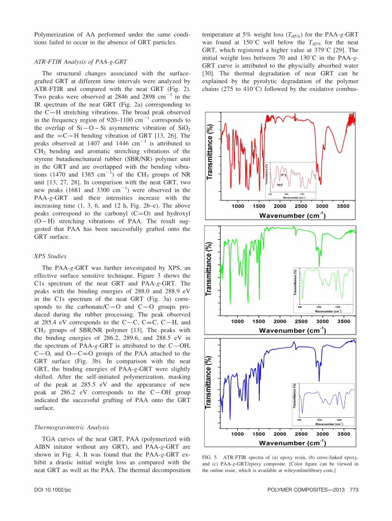
FIG. 5. ATR-FTIR spectra of (a) epoxy resin, (b) cross-linked epoxy,
and (c) PAA-g-GRT/epoxy composite. [Color figure can be viewed in
the online issue, which is available at wileyonlinelibrary.com.]
DOI 10.1002/pc POLYMER COMPOSITES—-2013 773

tion of carbon black (450–6508C) and pyrolyzed char in
the presence of air (650–8008C).
ATR-FTIR Analysis
Figure 5 shows the FTIR spectra of epoxy resin, cured
or cross-linked epoxy, and PAA-g-GRT/epoxy composite.
The IR spectrum of epoxy resin showed the presence of
characteristic absorption bands at 3030 and 3056 cm21
correspond to the aromatic C��H and CH��OH stretching
vibrations. The absorption bands at 2964, 2929, and
2872 cm21 attributed to the ��CH2 and ��CH3 asymmet-
rical and symmetrical stretching vibrations. The band at
1036 cm21 corresponds to the Ar��O��C stretching
vibration. The epoxy groups in IR spectrum was proved
by the presence of breathing vibration modes at 971
(bending C��H epoxy) and 915 cm21 (C��O epoxy). The
peak at 830 cm21 is ascribed to the aromatic 1,4 substitu-
tion of epoxy resin [31]. The absence of the oxirane
(m ) peaks at 971 and 915 cm21 and the absence of
these peaks in the cured epoxy and PAA-g-GRT/epoxycomposite confirmed that the curing process occurred
based on the addition reaction between epoxy and amine.
Most of the peaks of GRT and PAA were overlapped
with the epoxy peaks.
Mechanical Properties
Figure 6 shows the tensile and flexural properties of
the cured epoxy and neat GRT/epoxy composites (made
according to the ASTM D 638 and D 790) with different
weight fractions of the GRT. The tensile strength of cured
epoxy was 30.24 MPa, which was lower than 5 and 10%
neat GRT/epoxy composites, but higher than those of the
composites with 20, 30, and 40% GRT (Fig. 6a). The ini-
tial 120% increase in the tensile strength of composite
with 10% GRT is indicative of good adhesion between
the GRT particles and the epoxy matrix, resulting in a
positive toughening effect between the two. Generally,
fillers are added to the polymer matrix to produce a mate-
rial with low flexiblity having higher tensile strength and
modulus. This may be attributed to the reduced molecular
mobility of the polymer chains [32, 33]. The decrease in
strength at higher GRT content may be due to the disrup-
tion of the epoxy matrix as more GRT particle are added.
When compared with the composite with 30% GRT, a
slight increase in the tensile strength was observed for
40% composite. This may be due to the inhomogenity of
GRT particles in the epoxy matrix. The mechanical prop-
erties of the composite containing filler dispersed in the
polymer matrix depends on the structural continuity and
interfacial adhesion between the filler and matrix [10].
FIG. 6. Mechanical properties of the epoxy and neat GRT/epoxy composites. [Color figure can be viewed in the online issue, which is available at
wileyonlinelibrary.com.]
774 POLYMER COMPOSITES—-2013 DOI 10.1002/pc

The decrease in the tensile strength at higher GRT con-
centration was due to the nonadherence of the GRT par-
ticles with the epoxy matrix and the random distribution
of the excess GRT particles in the epoxy network. The
nonadherence of the GRT particles create voids in the ep-
oxy matrix and lead to agglomeration. This may result in
discontinuity of the structure and generates stress around
the GRT particles reducing the load capability resulitng in
the decrease of overall strength of the composite. The
variation of tensile modulus of the cured epoxy and neat
GRT/epoxy composites is shown in Fig. 6b. The tensile
modulus of cured epoxy was 0.71 GPa and that of 10%
neat GRT/epoxy composite was 1.08 GPa; it dropped to
0.62 GPa when the concentation of GRT is 30%. An
increase of 130% modulus was observed for composite
with 10 wt% GRT. The modulus of composite falls to a
lower value at higher GRT concentration. This may be
attributed to the decrease in brittleness of the epoxy ma-
trix as more GRT particles were added to the epoxy.
Figure 6c shows the flexural strength of cured epoxy
and neat GRT/epoxy composites. The flexural strength of
cured epoxy was 53.89 MPa and increased to 74.51 MPa
when the GRT content in composite was 10% but the
strength gradually decreases from 74.51 to 30.56 MPa as
the concentration of GRT increases from 10 to 40% in
the composite. Similar trend was observed for the flexural
modulus as well. The highest modulus of 2.53 GPa was
obtained for the composite with 10% GRT. The increase
in flexural strength (138%) and modulus (127%) was
observed for the composite with 10% GRT as compared
with the cured epoxy. It has been shown that a better dis-
persion of the filler in the epoxy matrix increases the flex-
ural modulus of the composite materials [11], which was
further explained by the percolation theory [12]. Accord-
ing to the theory, there is an associated zone correspond-
ing to the each particle in the polymer matrix which is
affected by a stress. The matrix zones join together when
the distance between the particle is smaller enough result-
ing in the formation of a percolation effect. This effect of
interfacial properties between the GRT particles and ep-
oxy matrix plays an important role in stress transfer and
the elastic deformation of the matrix to the GRT particles.
For a constant GRT loading, there is an increase in the
contact area of the matrix, which increases the interfacial
stiffness and facilitates the effective stress transfer,
thereby resulting in the increase of modulus. At higher
GRT content, the composite modulus decreases due to the
particle agglomeration.
Figure 7 shows the tensile and flexural properties of
the PAA-g-GRT/epoxy composites. The tensile strength
of PAA-g-GRT/epoxy composites decreases as the PAA-g-GRT content increases in the composite indicating a
FIG. 7. Mechanical properties of the GRT and PAA-g-GRT/epoxy composites. [Color figure can be viewed in the online issue, which is available at
wileyonlinelibrary.com.]

decrease in the toughness (Fig. 7a). When compared with
the neat GRT/epoxy composites, an increase in the tensile
modulus (Fig. 7b) and flexural strength (Fig. 7c), as well
as a significant increase in the flexural modulus (Fig. 7d)
was observed for the PAA-g-GRT/epoxy composites. A re-
markable increase in tensile and flexural modulus of 180%
was observed for the composite with 10% PAA-g-GRT,whereas 186% increase was calculated for the 40% com-
posite. In comparison with the cured epoxy, 10% PAA-g-GRT/epoxy composite registered a 229% increase in the
modulus indicating an increase in the stiffness of the com-
posite. Therefore, 10% GRT is the optimal to achieve
improved property of the composite.
Elongation at break % with respect to the different
wt% of GRT is shown in Table 1. The neat epoxy com-
posites exhibit a higher elongation at break % in compari-
son to GRT/epoxy composites and PAA-g-GRT/epoxycomposites with different wt% of GRT and PAA-g-GRT,respectively. GRT/epoxy and PAA-g-GRT composites with
10 wt% GRT, showed a lower elongation at break % with
higher tensile strength and modulus. This may be attributed
FIG. 8. SEM images of (a) neat GRT, (b) PAA-g-GRT, (c) neat epoxy, (d) PAA-g-GRT (40%)/epoxy, and (e) neat GRT (40%)/epoxy composites.
TABLE 1.
Composite Samples Elongation at break%
Neat Epoxy Composite 56
Epoxy/ GRT (10 wt %) 41
Epoxy/ GRT (20 wt %) 48
Epoxy/ GRT (40 wt %) 51
Epoxy/ PAA-g-GRT (10 wt %) 21
Epoxy/ PAA-g-GRT (20 wt %) 42
Epoxy/PAA-g- GRT (40 wt %) 45
776 POLYMER COMPOSITES—-2013 DOI 10.1002/pc
to the fact that it takes more force to elongate a material
having high strength and modulus. Similar trend was
observed in the case of PAA-g-GRT/epoxy composites.
Morphology
Figure 8 shows the SEM images of neat GRT, PAA-g-GRT, epoxy, PAA-g-GRT (40%)/epoxy, and GRT (40%)/
epoxy composites. From Fig. 8a, one can see that the as-
received GRT particles showed a typical morphology with
surface roughness. The GRT particles were in micron range,
which is consistent with the supplier’s statement. The appa-
rent physical nature of GRT particles (Fig. 8b) changed af-
ter surface-grafting by PAA and the surface roughness
decreases. The morphology of PAA-g-GRT changed
remarkably after the formation of composite with epoxy
(Fig. 8d). This is due to the reduction in the hardness of the
composite material, which is supported by our elongation at
break results. As a comparison, the SEM images of neat ep-
oxy and neat GRT/epoxy is given (Fig. 8c and e).
CONCLUSIONS
The self-initiated free radical polymerization of AA on
the surface of economically viable mechanochemically
devulcanized GRT particles were successfully achieved
via the stable mechano-free radicals present in the GRT.
The EPR analysis confirmed the presence of stable free
radicals present in the GRT with a g-factor of 2.0035,
which is similar to the g-factor of free electrons. The
PAA-g-GRT/epoxy composites showed significant
enhancement in the mechanical properties. In comparison
with the neat GRT/epoxy composite, an increase in the
tensile and flexural modulus of 180% was observed in the
PAA-g-GRT/epoxy composite. The PAA grafted GRT
resulted in a better filler material, which could adhere
well to the epoxy matrix. The GRT could be a cost effec-
tive and environmentally safe approach to replace the
conventional free radicals and costly fillers.
ACKNOWLEDGMENTS
The authors would like to extend thanks to the Lehigh
Technologies, LLC for their supply of raw materials. We
would like to acknowledge the Department of chemistry,
Clemson university and Robert A. Welch Foundation
(Grant No. AT-0041) at the University of Texas at Dallas
for their financial support.
REFERENCES
1. D.Y. Wu, S. Bateman, and M. Partlett, Compos. Sci.Technol., 67, 190 (2007).
2. R.H. Snyder, Scrap tires: Disposal and reuse, Society of
Automotive Engineers International, Warrendale, PA. (1998).
3. Rubber manufacturing Association (RMA). Scrap tire mar-
ket in the United States ( 2007).
4. S.K. De, Prog. Rubber. Plast. Technol., 17, 113 (2001).
5. W. Klingensmith and K.C. Baranwal, Rubber World.,218, 41 (1998).
6. S.B. Liang and Y.C. Hao, Adv. Powder Technol., 11,
187 (2000).
7. D. Mangaraj, Rubber Chem. Technol., 78, 536 (2005).
8. W. Dierkes, Rubber India., 48, 9 (1996).
9. Y.W. Song, H.S. Do, H.S. Joo, D.H. Lim, S. Kim,
and H.J. Kim, J. Adhesion Sci. Technol., 20, 1357 (2006).
10. A.A. Yehia, M.A. Mull, M.N. Ismail, Y.A. Hefny, and
E.M. Abdel-Bary, J. Appl. Polym. Sci., 93, 30 (2004).
11. X. Zhang, X. Zhu, M. Liang, and C. Lu, J. Appl.Polym. Sci., 114, 1118 (2009).
12. A.M. Shanmugharaj, J.K. Kim, and S.H. Ryu, Polym.Test. 24, 739 (2005).
13. A.K. Naskar, S.K. De, and A.K. Bhowmick, RubberChem. Technol., 74, 645 (2001).
14. A.K. Naskar, A.K. Bhowmick, and S.K. De, J. Appl.Polym. Sci., 84, 622 (2002).
15. M. Pittolo and R.P. Burford, J. Mater. Sci., 21, 1769 (1986).
16. I. Fuhrmann and J. Karger-Kocsis, J. Appl. Polym. Sci.,89, 1622–1628, (2003).
17. S. Coiai, E. Passaglia, F. Ciardelli, D. Tirelli, F. Peruz-
zotti, and E. Resmini, Macromol. Symp., 234, 193 (2006).
18. S. Coiai, E. Passaglia, and F. Ciardelli, Macromol.Chem. Phys., 207, 2289 (2006).
19. K.P.U. Perera, D.W. Smith, J.C. Moreland, and K.
Wallace, U. S. Patent 0,060, 711 A1 (2007).
20. M. Banda, A.K. Naskar, P.U. Perera, C. Moreland, T.
Hodge, K. Wallace, H.W. Beckham, and D.W. Smith,
Rubber Chem. Technol., 85, 68 (2012).
21. Y.A. Aggour, A.S. Al-Shihri, and M.R. Bazzt, Open J.Polym. Chem., 2, 70 (2012).
22. F. Cataldo, F. Padella, and F. Cavalieri, J. Appl. Polym.Sci., 90, 1631 (2003).
23. M. Sato, T. Ogata, and M. Hasegawa, Powder Technol.,85, 269 (1995).
24. J. Sohma and M. Sakaguchi, J. Appl. Polym. Sci., 22,
2915 (1978).
25. J. Sohma, M. Sakaguchi, and N. Kurokawa, J. Appl.Polym. Sci., 25, 1209 (1980).
26. B. McCool, L. Murphy, and C.P. Tripp, J. ColloidInterface Sci., 296, 294 (2006).
27. S. Gunasekharan, R.K. Natarajan, and A. Kala, Spectro-chim. Acta Part A., 68, 323 (2007).
28. S. Roy and P.P. De, Polym. Test., 11, 3 (1992).
29. S.H. Lee, M. Balasubramanian, and J.K. Kim, J. Appl.Polym. Sci., 106, 3209 (2007).
30. S. Dubinsky, G.S. Grader, G.E. Shter, and M.S. Silver-
tein, Polym. Degrad. Stab., 86, 171 (2004).
31. G. Nikolic, S. Zlatkovic, M. Cakic, S. Cakic, C.
Lacnjevac, and Z. Rajic, Sensors., 10, 684 (2010).
32. A.J. Gu, S.W. Kuo, and F.C. Chang, J. Appl. Polym.Sci., 79, 1902 (2001).
33. Y. Yang, Z.K. Zhu, J. Yin, X.Y. Wang, and Z.N Qi,
Polymer., 40, 4407 (1999).
DOI 10.1002/pc POLYMER COMPOSITES—-2013 777