SURFACE PHASE TRANSFORMATION IN by ... - physics.byu.edu
31
SURFACE PHASE TRANSFORMATION IN LITHIUM ALUMINATE by Gordon Mancuso A senior thesis submitted to the faculty of Brigham Young University in partial fulfillment of the requirements for the degree of Bachelor of Science Department of Physics and Astronomy Brigham Young University August 2008
Transcript of SURFACE PHASE TRANSFORMATION IN by ... - physics.byu.edu
SURFACE PHASE TRANSFORMATION IN
LITHIUM ALUMINATE
by
Gordon Mancuso
A senior thesis submitted to the faculty of
Brigham Young University
in partial fulfillment of the requirements for the degree of
Bachelor of Science
Department of Physics and Astronomy
Brigham Young University
August 2008
Copyright c© 2008 Gordon Mancuso
All Rights Reserved
BRIGHAM YOUNG UNIVERSITY
DEPARTMENT APPROVAL
of a senior thesis submitted by
Gordon Mancuso
This thesis has been reviewed by the research advisor, research coordinator,and department chair and has been found to be satisfactory.
Date Richard Vanfleet, Advisor
Date Eric Hintz, Research Coordinator
Date Ross Spencer, Chair
ABSTRACT
SURFACE PHASE TRANSFORMATION IN
LITHIUM ALUMINATE
Gordon Mancuso
Department of Physics and Astronomy
Bachelor of Science
Gamma phase lithium aluminate (γ-LiAlO2) has been proposed as a possi-
ble substrate for gallium nitride growth. A corrugation or stripe pattern of
beta phase LiAlO2 forms on the surface of γ-LiAlO2 wafers. We attempt to
determine the cause of the phase transformation. The beta phase re-forms
immediately after removal. This supports the conclusion that the beta phase
is more stable at room temperature than the gamma phase, and suggests that
the growth of the beta phase is strain limited.
ACKNOWLEDGMENTS
I would like to thank Dr. Vanfleet for his endless insight and answers. I
would also like to thank Katie Hurd for teaching me how to use the AFM.
Finally, I am in great debt to my wife, Megan, who’s patience with me as I
completed this work seemed to know no bounds.
This research was supported by the National Science Foundation PHY
0552795 and the BYU Physics Department.
Contents
Table of Contents vi
List of Figures vii
1 Introduction 11.1 Gallium Nitride . . . . . . . . . . . . . . . . . . . . . . . . . . . . . . 11.2 Lithium Aluminate . . . . . . . . . . . . . . . . . . . . . . . . . . . . 21.3 LiAlO2 Surface Corrugation . . . . . . . . . . . . . . . . . . . . . . . 2
2 Experimental Setup 52.1 Atomic Force Microscopy . . . . . . . . . . . . . . . . . . . . . . . . . 52.2 LiAlO2 Samples . . . . . . . . . . . . . . . . . . . . . . . . . . . . . . 62.3 Sample Holder . . . . . . . . . . . . . . . . . . . . . . . . . . . . . . . 72.4 Polishing Method . . . . . . . . . . . . . . . . . . . . . . . . . . . . . 92.5 Attempts at Morphology Removal . . . . . . . . . . . . . . . . . . . . 10
3 Results and Conclusion 123.1 Beta Phase Re-forms . . . . . . . . . . . . . . . . . . . . . . . . . . . 123.2 Colloidal Silica . . . . . . . . . . . . . . . . . . . . . . . . . . . . . . 143.3 Other Attempts . . . . . . . . . . . . . . . . . . . . . . . . . . . . . . 15
3.3.1 Heating . . . . . . . . . . . . . . . . . . . . . . . . . . . . . . 153.3.2 Flipping the Sample . . . . . . . . . . . . . . . . . . . . . . . 163.3.3 Side View . . . . . . . . . . . . . . . . . . . . . . . . . . . . . 16
3.4 Formation Theory . . . . . . . . . . . . . . . . . . . . . . . . . . . . . 173.5 Conclusion . . . . . . . . . . . . . . . . . . . . . . . . . . . . . . . . . 22
Bibliography 23
vi

List of Figures
1.1 Surface Corrugation . . . . . . . . . . . . . . . . . . . . . . . . . . . . 21.2 TEM Image of Mesa . . . . . . . . . . . . . . . . . . . . . . . . . . . 41.3 Tetragonal Crystal Structure . . . . . . . . . . . . . . . . . . . . . . . 4
2.1 AFM Function . . . . . . . . . . . . . . . . . . . . . . . . . . . . . . 62.2 Etched LiAlO2 . . . . . . . . . . . . . . . . . . . . . . . . . . . . . . 72.3 Unetched LiAlO2 . . . . . . . . . . . . . . . . . . . . . . . . . . . . . 82.4 Tripod Polisher . . . . . . . . . . . . . . . . . . . . . . . . . . . . . . 82.5 Machined Cylinder . . . . . . . . . . . . . . . . . . . . . . . . . . . . 9
3.1 Diamond Polished LiAlO2, Beta Phase Visible . . . . . . . . . . . . . 133.2 Diamond Polished LiAlO2, More Pronounced Beta Phase . . . . . . . 133.3 Colloidal Silica Polished LiAlO2 . . . . . . . . . . . . . . . . . . . . . 143.4 Diamond Polished LiAlO2, Side 1 . . . . . . . . . . . . . . . . . . . . 163.5 Diamond Polished LiAlO2, Side 2 . . . . . . . . . . . . . . . . . . . . 173.6 Tetragonal Crystal Structure . . . . . . . . . . . . . . . . . . . . . . . 183.7 Sandwich Mounting of LiAlO2 . . . . . . . . . . . . . . . . . . . . . . 183.8 Second a Face, Diamond Polished . . . . . . . . . . . . . . . . . . . . 193.9 Second a Face, Colloidal Silica Polished . . . . . . . . . . . . . . . . . 193.10 Beta Phase Formation Theory Schematic . . . . . . . . . . . . . . . . 21
vii
Chapter 1
Introduction
1.1 Gallium Nitride
Gallium Nitride (GaN) is a wide bandgap semiconductor that is currently used in
consumer electronics to create blue light emitting devices and white light LED’s. For
example, GaN is used in the laser diodes found in Blu-ray recorders and players [1].
It is also used in LED flashlights [2]. GaN is typically grown on a sapphire substrate
by metal-organic vapor phase epitaxy (MOVPE) [3]. However, sapphire is not an
ideal substrate for the growth of GaN. The lattice mismatch between the two crystals
approaches 15%, and the thermal expansion coefficients are different [4]. Both of
these lead to large defect densities on the order of 1010/cm2 in the grown GaN [5],
which limits its usefulness in many areas. Silicon carbide (SiC) is another substrate
that has been used for GaN growth. The SiC lattice more closely matches that of
GaN, but its high cost limits its potential [5].
1
1.2 Lithium Aluminate 2
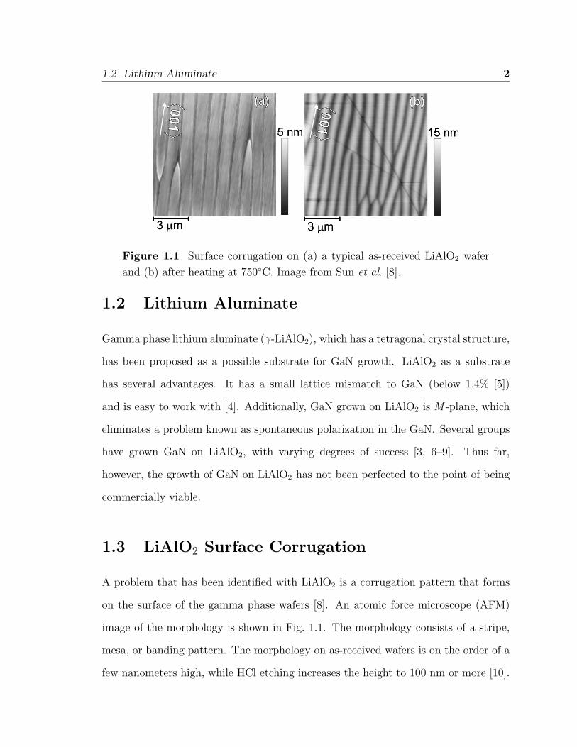
Figure 1.1 Surface corrugation on (a) a typical as-received LiAlO2 wafer
and (b) after heating at 750◦C. Image from Sun et al. [8].
1.2 Lithium Aluminate
Gamma phase lithium aluminate (γ-LiAlO2), which has a tetragonal crystal structure,
has been proposed as a possible substrate for GaN growth. LiAlO2 as a substrate
has several advantages. It has a small lattice mismatch to GaN (below 1.4% [5])
and is easy to work with [4]. Additionally, GaN grown on LiAlO2 is M -plane, which
eliminates a problem known as spontaneous polarization in the GaN. Several groups
have grown GaN on LiAlO2, with varying degrees of success [3, 6–9]. Thus far,
however, the growth of GaN on LiAlO2 has not been perfected to the point of being
commercially viable.
1.3 LiAlO2 Surface Corrugation
A problem that has been identified with LiAlO2 is a corrugation pattern that forms
on the surface of the gamma phase wafers [8]. An atomic force microscope (AFM)
image of the morphology is shown in Fig. 1.1. The morphology consists of a stripe,
mesa, or banding pattern. The morphology on as-received wafers is on the order of a
few nanometers high, while HCl etching increases the height to 100 nm or more [10].
1.3 LiAlO2 Surface Corrugation 3
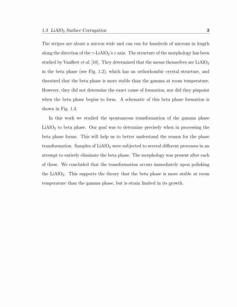
The stripes are about a micron wide and can run for hundreds of microns in length
along the direction of the γ-LiAlO2’s c axis. The structure of the morphology has been
studied by Vanfleet et al. [10]. They determined that the mesas themselves are LiAlO2
in the beta phase (see Fig. 1.2), which has an orthorhombic crystal structure, and
theorized that the beta phase is more stable than the gamma at room temperature.
However, they did not determine the exact cause of formation, nor did they pinpoint
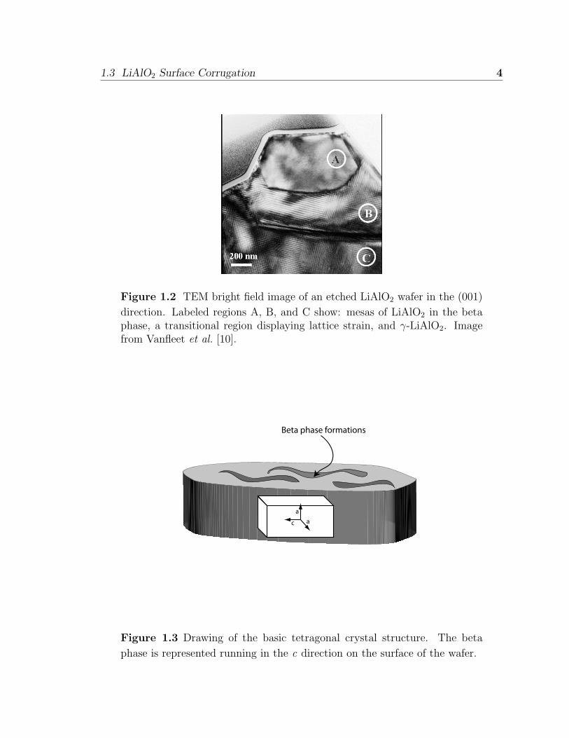
when the beta phase begins to form. A schematic of this beta phase formation is
shown in Fig. 1.3.
In this work we studied the spontaneous transformation of the gamma phase
LiAlO2 to beta phase. Our goal was to determine precisely when in processing the
beta phase forms. This will help us to better understand the reason for the phase
transformation. Samples of LiAlO2 were subjected to several different processes in an
attempt to entirely eliminate the beta phase. The morphology was present after each
of these. We concluded that the transformation occurs immediately upon polishing
the LiAlO2. This supports the theory that the beta phase is more stable at room
temperature than the gamma phase, but is strain limited in its growth.
1.3 LiAlO2 Surface Corrugation 4
Figure 1.2 TEM bright field image of an etched LiAlO2 wafer in the (001)
direction. Labeled regions A, B, and C show: mesas of LiAlO2 in the betaphase, a transitional region displaying lattice strain, and γ-LiAlO2. Imagefrom Vanfleet et al. [10].
c aa
Beta phase formations
Figure 1.3 Drawing of the basic tetragonal crystal structure. The beta
phase is represented running in the c direction on the surface of the wafer.
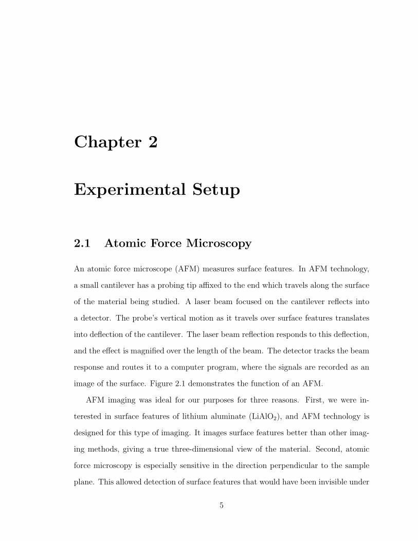
Chapter 2
Experimental Setup
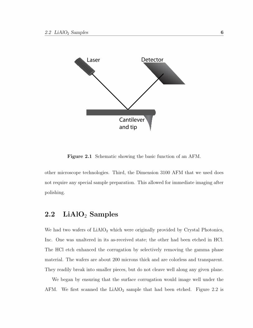
2.1 Atomic Force Microscopy
An atomic force microscope (AFM) measures surface features. In AFM technology,
a small cantilever has a probing tip affixed to the end which travels along the surface
of the material being studied. A laser beam focused on the cantilever reflects into
a detector. The probe’s vertical motion as it travels over surface features translates
into deflection of the cantilever. The laser beam reflection responds to this deflection,
and the effect is magnified over the length of the beam. The detector tracks the beam
response and routes it to a computer program, where the signals are recorded as an
image of the surface. Figure 2.1 demonstrates the function of an AFM.
AFM imaging was ideal for our purposes for three reasons. First, we were in-
terested in surface features of lithium aluminate (LiAlO2), and AFM technology is
designed for this type of imaging. It images surface features better than other imag-
ing methods, giving a true three-dimensional view of the material. Second, atomic
force microscopy is especially sensitive in the direction perpendicular to the sample
plane. This allowed detection of surface features that would have been invisible under
5
2.2 LiAlO2 Samples 6
DetectorLaser
Cantilever and tip
Figure 2.1 Schematic showing the basic function of an AFM.
other microscope technologies. Third, the Dimension 3100 AFM that we used does
not require any special sample preparation. This allowed for immediate imaging after
polishing.
2.2 LiAlO2 Samples
We had two wafers of LiAlO2 which were originally provided by Crystal Photonics,
Inc. One was unaltered in its as-received state; the other had been etched in HCl.
The HCl etch enhanced the corrugation by selectively removing the gamma phase
material. The wafers are about 200 microns thick and are colorless and transparent.
They readily break into smaller pieces, but do not cleave well along any given plane.
We began by ensuring that the surface corrugation would image well under the
AFM. We first scanned the LiAlO2 sample that had been etched. Figure 2.2 is
2.3 Sample Holder 7
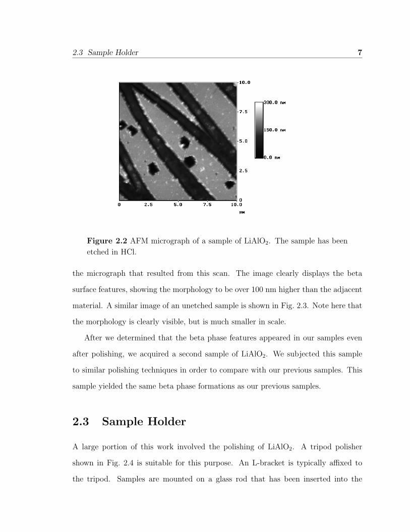
Figure 2.2 AFM micrograph of a sample of LiAlO2. The sample has been
etched in HCl.
the micrograph that resulted from this scan. The image clearly displays the beta
surface features, showing the morphology to be over 100 nm higher than the adjacent
material. A similar image of an unetched sample is shown in Fig. 2.3. Note here that
the morphology is clearly visible, but is much smaller in scale.
After we determined that the beta phase features appeared in our samples even
after polishing, we acquired a second sample of LiAlO2. We subjected this sample
to similar polishing techniques in order to compare with our previous samples. This
sample yielded the same beta phase formations as our previous samples.
2.3 Sample Holder
A large portion of this work involved the polishing of LiAlO2. A tripod polisher
shown in Fig. 2.4 is suitable for this purpose. An L-bracket is typically affixed to
the tripod. Samples are mounted on a glass rod that has been inserted into the
2.3 Sample Holder 8
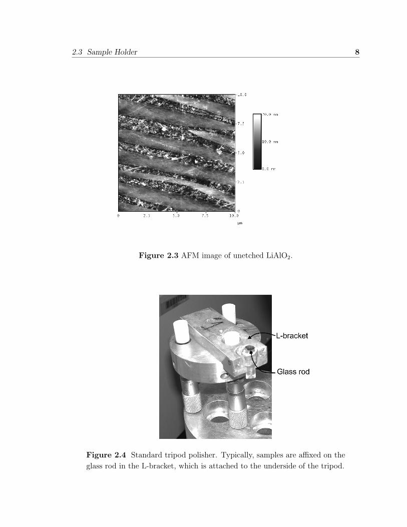
Figure 2.3 AFM image of unetched LiAlO2.
Figure 2.4 Standard tripod polisher. Typically, samples are affixed on the
glass rod in the L-bracket, which is attached to the underside of the tripod.
2.4 Polishing Method 9
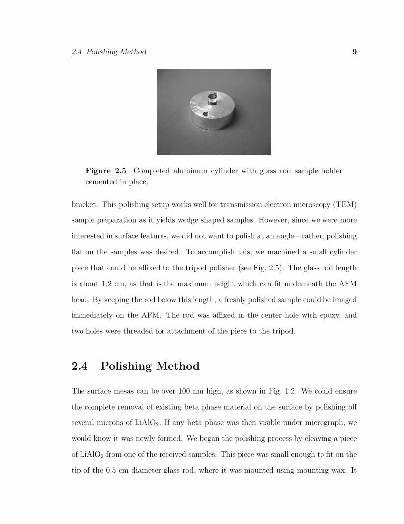
Figure 2.5 Completed aluminum cylinder with glass rod sample holder
cemented in place.
bracket. This polishing setup works well for transmission electron microscopy (TEM)
sample preparation as it yields wedge shaped samples. However, since we were more
interested in surface features, we did not want to polish at an angle—rather, polishing
flat on the samples was desired. To accomplish this, we machined a small cylinder
piece that could be affixed to the tripod polisher (see Fig. 2.5). The glass rod length
is about 1.2 cm, as that is the maximum height which can fit underneath the AFM
head. By keeping the rod below this length, a freshly polished sample could be imaged
immediately on the AFM. The rod was affixed in the center hole with epoxy, and
two holes were threaded for attachment of the piece to the tripod.
2.4 Polishing Method
The surface mesas can be over 100 nm high, as shown in Fig. 1.2. We could ensure
the complete removal of existing beta phase material on the surface by polishing off
several microns of LiAlO2. If any beta phase was then visible under micrograph, we
would know it was newly formed. We began the polishing process by cleaving a piece
of LiAlO2 from one of the received samples. This piece was small enough to fit on the
tip of the 0.5 cm diameter glass rod, where it was mounted using mounting wax. It
2.5 Attempts at Morphology Removal 10
was useful to make a small sketch of the sample, which helped in determining which
side had been polished once the sample was removed from the rod.
Once the sample was affixed to the tripod, it was polished with a 30 µm alu-
minum oxide (Al2O3) lapping film. Lapping films are basically high precision pieces
of sandpaper. The film was placed on a polishing wheel, which can rotate at up to 500
rpm. We began the process with a large grit size to ensure that all of the beta phase
morphology was removed during polishing. Once enough material was removed to
ensure removal of the surface morphology, the sample was polished with progressively
smaller grit sizes, using both Al2O3 and diamond lapping films. The final polish was
a 0.05 µm diamond suspension. Attempts to use colloidal silica as a final polish met
with interesting results (see Sec. 3.2).
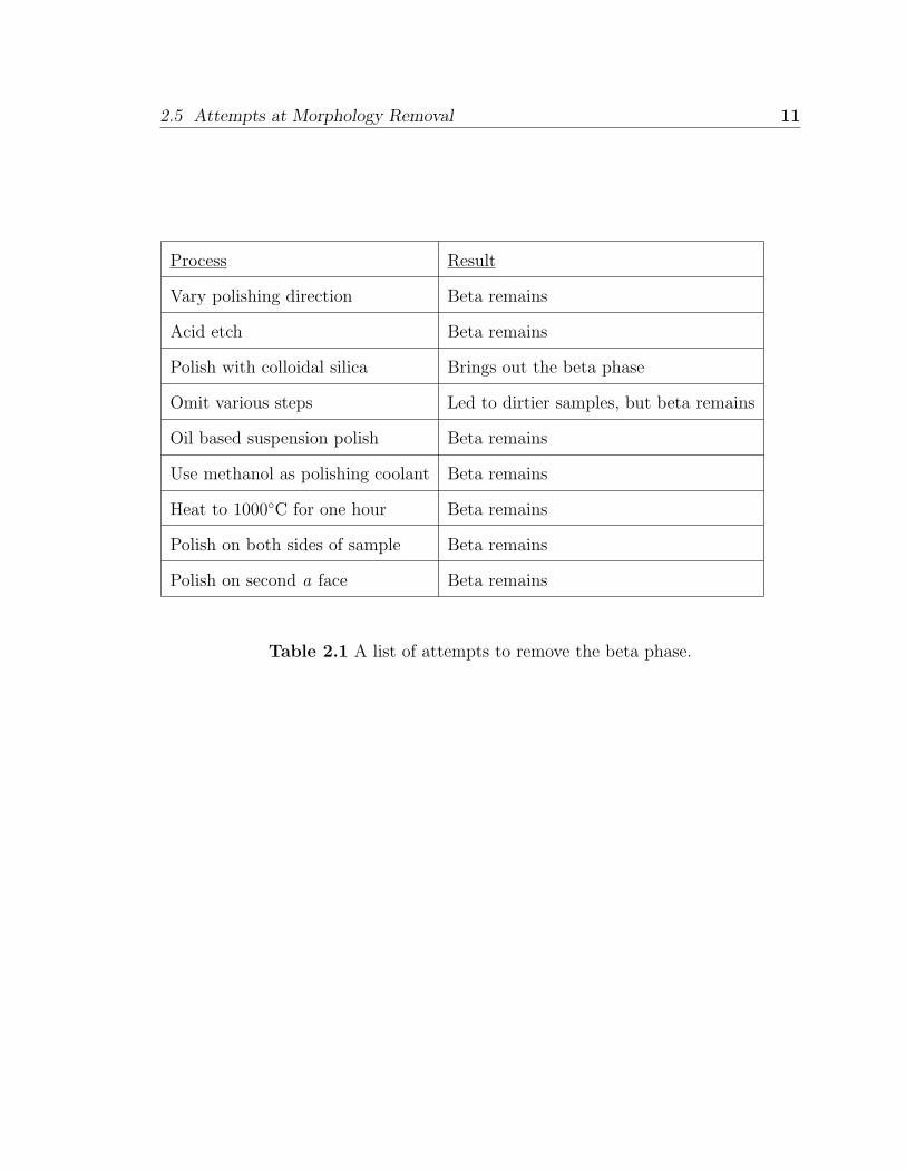
2.5 Attempts at Morphology Removal
To understand the beta phase growth, we tried a variety of processes in an attempt
to inhibit or enhance its formation. Table 2.1 lists these along with the result of each.
The results of these are covered in greater detail in Chap. 3.
2.5 Attempts at Morphology Removal 11
Process Result
Vary polishing direction Beta remains
Acid etch Beta remains
Polish with colloidal silica Brings out the beta phase
Omit various steps Led to dirtier samples, but beta remains
Oil based suspension polish Beta remains
Use methanol as polishing coolant Beta remains
Heat to 1000◦C for one hour Beta remains
Polish on both sides of sample Beta remains
Polish on second a face Beta remains
Table 2.1 A list of attempts to remove the beta phase.
Chapter 3
Results and Conclusion
3.1 Beta Phase Re-forms
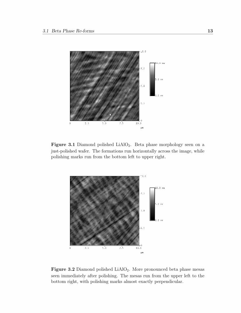
We polished several samples using our standard polishing procedure (see Sec. 2.4),
then imaged them immediately following polishing (see Figs. 3.1 and 3.2). In both of
these, special care was taken to polish as well as possible so that the beta phase would
not be obscured by polishing marks. In Fig. 3.1, we see polishing marks running from
the bottom left to the top right. We deliberately polished in a direction somewhat
perpendicular to the morphology direction to see if that had any effect on the phase
transformation. At first glance, the surfaces appear to be fairly flat, with minimal
features even with a vertical scale of 10 nm over a 10 µm surface. Note, however,
that closer inspection shows evidence of beta phase mesas in the horizontal direction.
The pattern is even more pronounced in Fig. 3.2. Here the small polishing marks can
be seen almost exactly perpendicular to the beta phase features. The presence of the
features immediately after polishing supports the conclusion that the beta phase is
more stable at room temperature.
12
3.1 Beta Phase Re-forms 13
Figure 3.1 Diamond polished LiAlO2. Beta phase morphology seen on a
just-polished wafer. The formations run horizontally across the image, whilepolishing marks run from the bottom left to upper right.
Figure 3.2 Diamond polished LiAlO2. More pronounced beta phase mesas
seen immediately after polishing. The mesas run from the upper left to thebottom right, with polishing marks almost exactly perpendicular.
3.2 Colloidal Silica 14
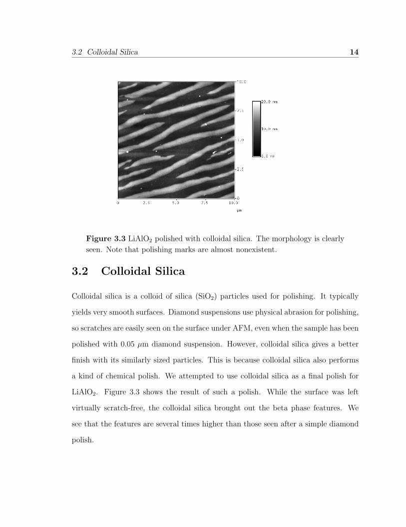
Figure 3.3 LiAlO2 polished with colloidal silica. The morphology is clearly
seen. Note that polishing marks are almost nonexistent.
3.2 Colloidal Silica
Colloidal silica is a colloid of silica (SiO2) particles used for polishing. It typically
yields very smooth surfaces. Diamond suspensions use physical abrasion for polishing,
so scratches are easily seen on the surface under AFM, even when the sample has been
polished with 0.05 µm diamond suspension. However, colloidal silica gives a better
finish with its similarly sized particles. This is because colloidal silica also performs
a kind of chemical polish. We attempted to use colloidal silica as a final polish for
LiAlO2. Figure 3.3 shows the result of such a polish. While the surface was left
virtually scratch-free, the colloidal silica brought out the beta phase features. We
see that the features are several times higher than those seen after a simple diamond
polish.
3.3 Other Attempts 15
3.3 Other Attempts
To strengthen the theory that the beta phase is more stable at room temperature
than the gamma phase, we attempted several different processes to ensure that no
part of the sample preparation process was causing the mesa formation. These are
listed in Table 2.1. Some of these have already been discussed. We will now explain
the others, devoting more space to those that are particularly interesting.
After polishing a sample, it was typically cleaned before AFM imaging. We omit-
ted each step of the cleaning process to make sure that no particular chemical was
responsible for the beta phase formation. The beta phase still formed after each of
these omissions. We also tried using different polishing techniques. Specifically, we
polished with an oil based diamond suspension and also tried polishing with methanol
instead of water as a coolant. Both of these similarly yielded beta phase formations.
We also acid etched samples in several acids: hydrochloric, sulfuric, phosphoric,
nitric, and acetic. With the exception of acetic acid, which did not etch the LiAlO2 at
all, all of these acids selectively etched the gamma phase material over the beta phase
material. This left the beta phase mesas standing much higher than the surrounding
material.
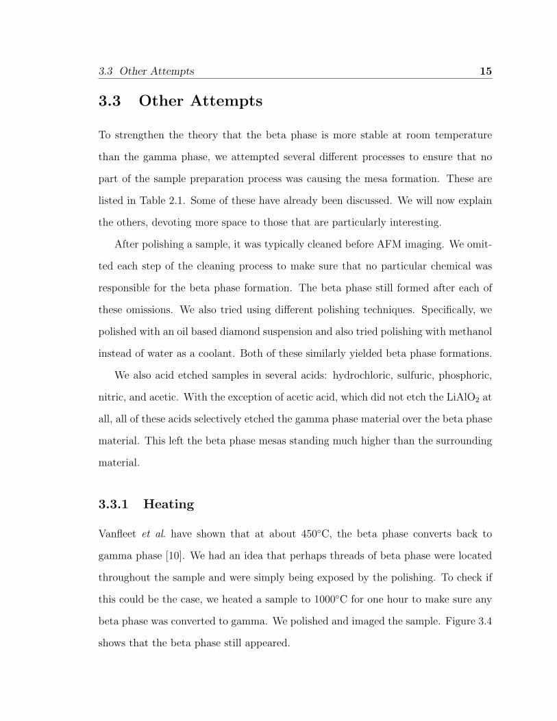
3.3.1 Heating
Vanfleet et al. have shown that at about 450◦C, the beta phase converts back to
gamma phase [10]. We had an idea that perhaps threads of beta phase were located
throughout the sample and were simply being exposed by the polishing. To check if
this could be the case, we heated a sample to 1000◦C for one hour to make sure any
beta phase was converted to gamma. We polished and imaged the sample. Figure 3.4
shows that the beta phase still appeared.
3.3 Other Attempts 16
Figure 3.4 Side 1 of a LiAlO2 sample that has been heated to 1000◦C for
one hour, then diamond polished.
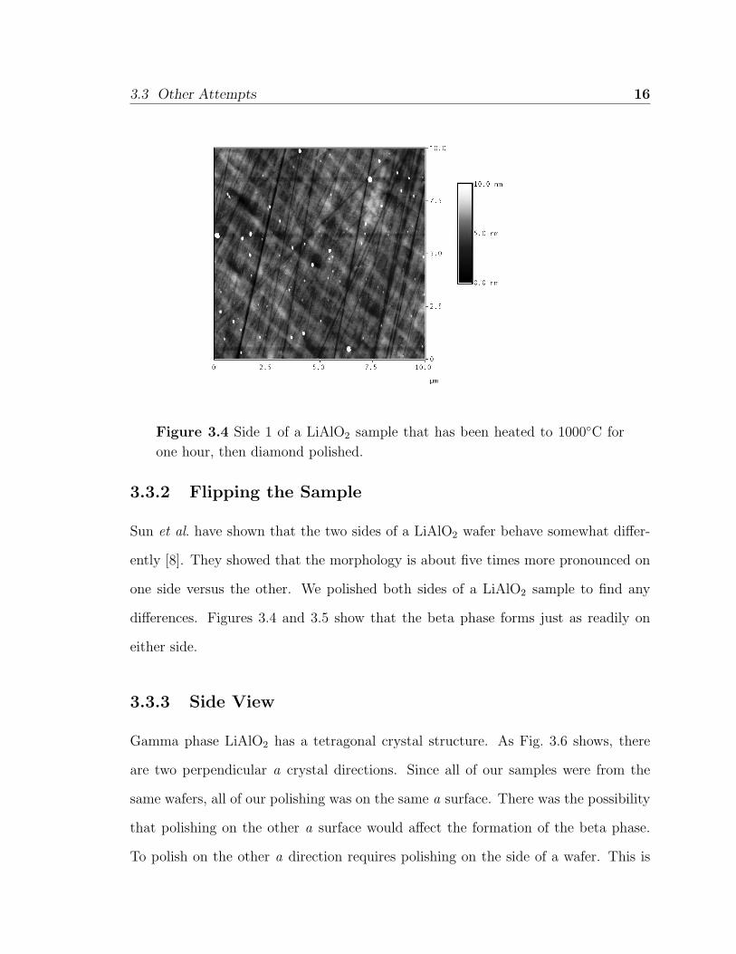
3.3.2 Flipping the Sample
Sun et al. have shown that the two sides of a LiAlO2 wafer behave somewhat differ-
ently [8]. They showed that the morphology is about five times more pronounced on
one side versus the other. We polished both sides of a LiAlO2 sample to find any
differences. Figures 3.4 and 3.5 show that the beta phase forms just as readily on
either side.
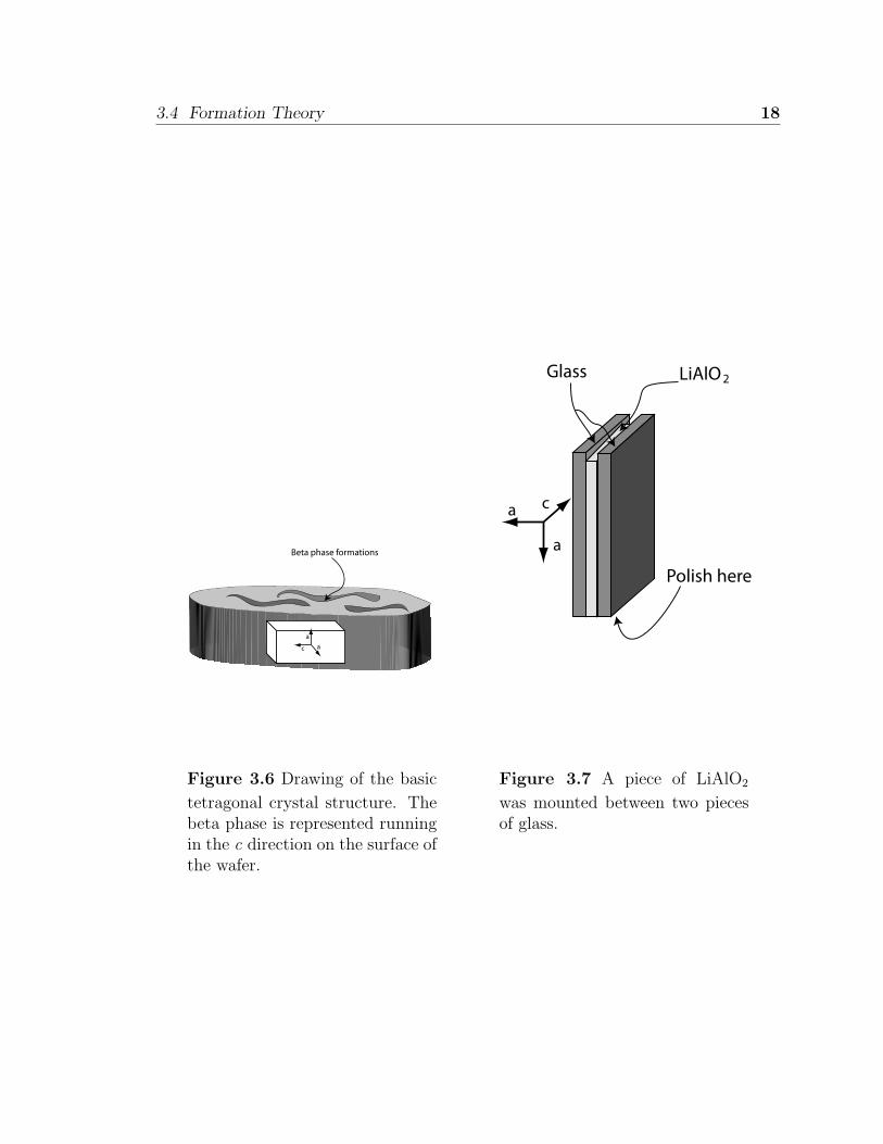
3.3.3 Side View
Gamma phase LiAlO2 has a tetragonal crystal structure. As Fig. 3.6 shows, there
are two perpendicular a crystal directions. Since all of our samples were from the
same wafers, all of our polishing was on the same a surface. There was the possibility
that polishing on the other a surface would affect the formation of the beta phase.
To polish on the other a direction requires polishing on the side of a wafer. This is
3.4 Formation Theory 17
Figure 3.5 Side 2 of a LiAlO2 sample that has been diamond polished. Note
that the beta phase is still visible.
not done easily. We found the direction of the beta phase growth on a sample, then
mounted the sample between two pieces of glass as in Fig. 3.7. This added strength
allowed the sample to be mounted on the sample holder on its side. The sample was
polished and imaged. As can be seen in Figs. 3.8 and 3.9, the beta phase is still
visible, though it does appear distorted. We attribute this to the fact that the piece
was probably not mounted at precisely the right angle to polish flat on the second a
face.
3.4 Formation Theory
Every process performed on the LiAlO2 points to the conclusion that the beta phase
re-forms immediately upon surface polishing. This supports the theory that the beta
phase is more stable at room temperature. The fact that the beta phase structures
form in bands along the c axis of the gamma phase material also supports the idea
3.4 Formation Theory 18
c aa
Beta phase formations
Figure 3.6 Drawing of the basic
tetragonal crystal structure. Thebeta phase is represented runningin the c direction on the surface ofthe wafer.
Polish here
ca
a
Glass LiAlO 2
Figure 3.7 A piece of LiAlO2
was mounted between two piecesof glass.
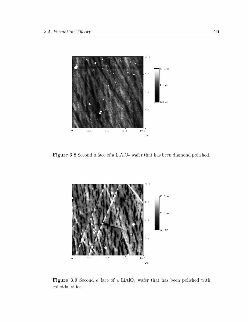
3.4 Formation Theory 19
Figure 3.8 Second a face of a LiAlO2 wafer that has been diamond polished.
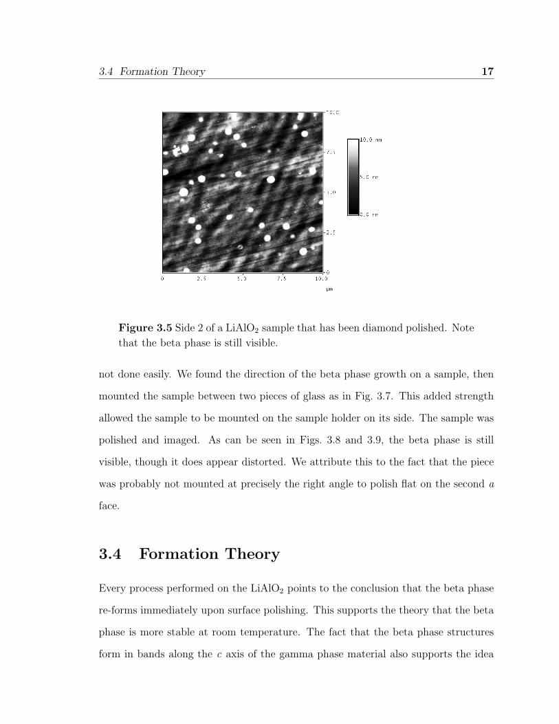
Figure 3.9 Second a face of a LiAlO2 wafer that has been polished with
colloidal silica.
3.4 Formation Theory 20
of strain limiting the growth of the beta phase.
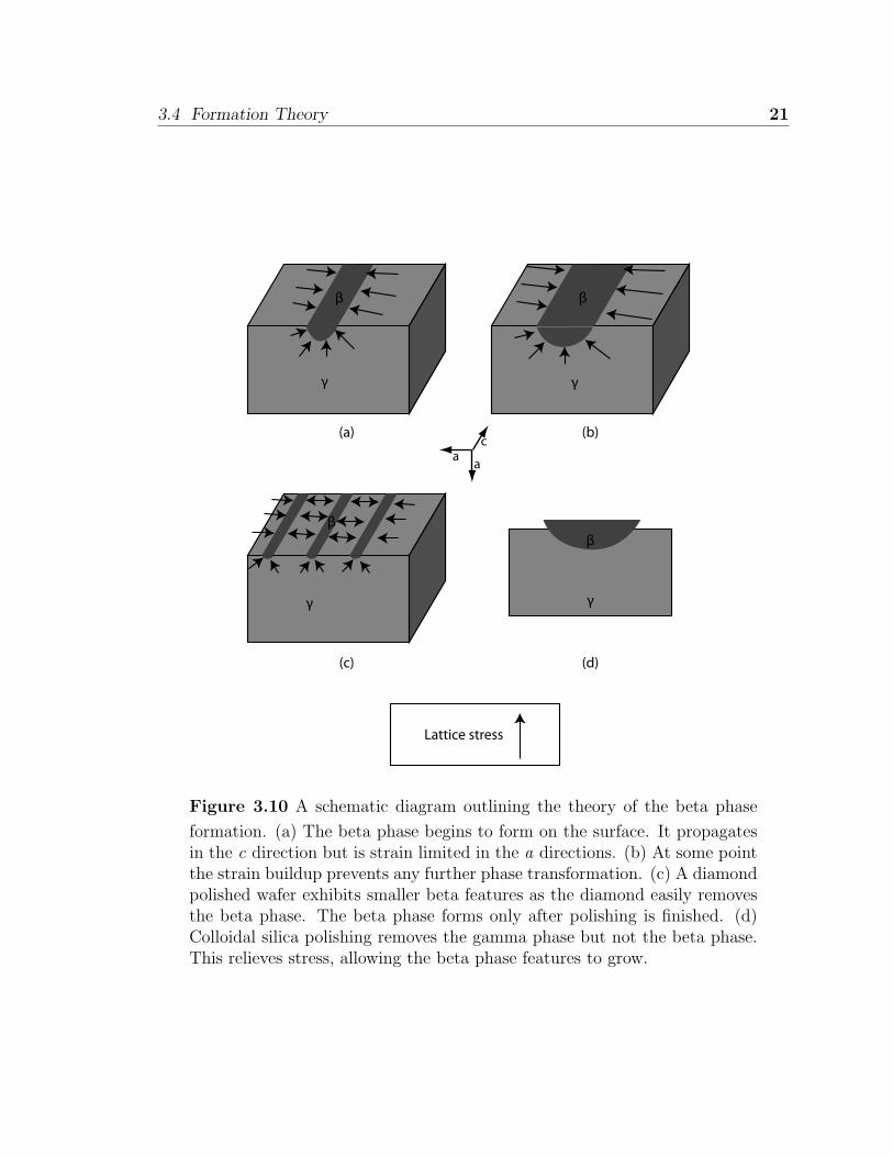
Figure 3.10 gives a basic outline of the theory of beta phase growth. We start with
the premise that the beta phase is more stable than the gamma phase. The relative
freedom at the surface of a γ-LiAlO2 sample allows the gamma phase lattice to realign
to the thermodynamically more stable beta phase. As this transformation proceeds,
strain due to lattice mismatch builds up at the boundary between the beta phase
and the gamma phase. At some point, the strain becomes large enough to make the
transformation thermodynamically unfavorable. Along the c axis, however, the strain
is minimal, allowing long mesas to form in that direction. We can understand this
quantitatively by examining the crystal structures of the beta and gamma phases.
γ-LiAlO2 has a tetragonal lattice structure (space group P41212) with lattice con-
stants of a = 0.5168 nm and c = 0.6268 nm [11]. The beta phase is orthorhombic
(Pna21) with lattice constants a = 0.528 nm, b = 0.630 nm, and c = 0.490 nm. Ex-
perimentally, the beta b axis aligns with the gamma c axis (0.630 nm with 0.6268 nm,
0.5% mismatch), the beta a axis aligns with the in-plane gamma a axis (0.528 nm
with 0.5168 nm, 2.2% mismatch), and the beta c axis aligns with the out-of-plane
gamma a axis (0.490 nm with 0.5168 nm, 5.2% mismatch). There is also a very good
match in the lowest mismatch directions with the actual atomic positions [10]. The
largest mismatch is in the out of plane direction where growth of the beta phase
would cause significant stress. Growth of the beta phase in the in-plane a direction
would cause less (but still significant) stress, while growth in the in-plane c direction
would cause very little stress. Thus, long mesas form along the c direction while the
increase in stress limits the growth in the other two directions.
Diamond polishing easily removes the beta phase as well as the gamma phase
material. This is why we see such small and faint formations on samples that have
been diamond polished. The beta phase forms after polishing has finished, and the
3.4 Formation Theory 21
β
γ
(a) (b)
(c) (d)
β
γ
c
aa
Lattice stress
γ
β
γ
β
Figure 3.10 A schematic diagram outlining the theory of the beta phase
formation. (a) The beta phase begins to form on the surface. It propagatesin the c direction but is strain limited in the a directions. (b) At some pointthe strain buildup prevents any further phase transformation. (c) A diamondpolished wafer exhibits smaller beta features as the diamond easily removesthe beta phase. The beta phase forms only after polishing is finished. (d)Colloidal silica polishing removes the gamma phase but not the beta phase.This relieves stress, allowing the beta phase features to grow.
3.5 Conclusion 22
formation size is quickly limited by lattice strain. However, colloidal silica polishing
yields much larger and well-pronounced beta phase formations. We believe there are
two reasons for this. First, it appears that colloidal silica selects the gamma phase over
the beta. This by itself would increase the relative size of the beta phase formations
as the surrounding gamma phase material is removed. As the gamma phase is cleared
away, the lattice strain would also decrease, allowing the beta phase to grow in size.
Second, since colloidal silica does not remove the beta phase as diamond does, the
beta phase has a chance to grow during the polishing process. This “massaging” of
the crystal lattice allows the structure to seek more stable arrangements, yielding still
more pronounced beta phase structures.
3.5 Conclusion
The most important finding of this work is that beta phase formations appear on the
surface of γ-LiAlO2 samples immediately after polishing. This supports the hypoth-
esis that the beta phase is more stable than the gamma phase at room temperature.
We were able to give this theory more support as we observed the phase transforma-
tion no matter what was done to the LiAlO2. We also give evidence that the beta
phase growth is strain limited in the a directions, but not in the c direction.
Bibliography
[1] “Sony Global - Laser Diode,” http://www.sony.net/Products/SC-HP/
laserdiodewld/tec/index03.html (Accessed 9 July 2008).
[2] “LED Flashlight Colors and Applications Guide and Color Characteristics,”
http://www.led-flashlight-store.com/colors-applications-guide.html (Accessed 9
July 2008).
[3] H. P. Maruska, D. W. Hill, M. C. Chou, J. J. Gallagher, and B. H. Chai,
“Free-standing non-polar gallium nitride substrates,” Opto-Electron. Rev. 11,
7 (2003).
[4] M. M. C. Chou, S. J. Huang, and C. W. C. Hsu, “Crystal growth and polishing
method of lithium aluminum oxide crystal,” J. Crystal Growth 303, 585 (2007).
[5] M. M. C. Chou, H. C. Huang, D.-S. Gan, and C. W. C. Hsu, “Defect character-
izations of γ-LiAlO2 single crystals,” J. Crystal Growth 291, 485 (2006).
[6] R. R. Vanfleet, J. A. Simmons, H. P. Maruska, D. W. Hill, M. M. C. Chou, and
B. H. Chai, “Defects in m-face GaN films grown by halide vapor phase epitaxy
on LiAlO2,” Appl. Phys. Lett. 83, 1139 (2003).
[7] P. Waltereit, O. Brandt, M. Ramsteiner, R. Uecker, P. Reiche, and K. H. Ploog,
23
BIBLIOGRAPHY 24
“Growth of M -plane GaN(1100) on γ-LiAlO2(100),” J. Crystal Growth 218, 143
(2000).
[8] Y. J. Sun, O. Brandt, and K. H. Ploog, “Growth of M -plane GaN films on
γ-LiAlO2,” J. Vac. Sci. Technol. B 21, 1350 (2003).
[9] M. M. C. Chou, D. R. Hang, H. Kalisch, R. H. Jansen, Y. Dikme, M. Heuken,
and G. P. Yablonskii, “Crystal growth and properties of LiAlO2 and nonpolar
GaN on LiAlO2 substrate,” J. Appl. Phys. 101, 103106 (2007).
[10] R. R. Vanfleet, J. A. Simmons, D. W. Hill, M. M. C. Chou, and B. H. Chai,
“Anti-Phase Ordering and Surface Phases in Lithium Aluminate,” (Submitted
to J. Appl. Phys.).
[11] M. Marezio, “The Crystal Structure and Anomalous Dispersion of γ-LiAlO2,”
Acta Cryst. 19, 396 (1965).