SURFACE GEOPHYSICAL METHODS FOR DETECTION OF · PDF fileSURFACE GEOPHYSICAL METHODS FOR...
18
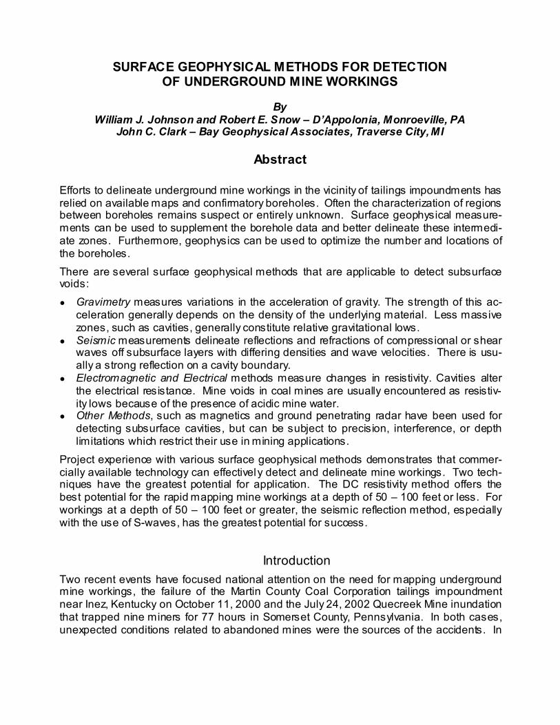
SURFACE GEOPHYSICAL METHODS FOR DETECTION OF UNDERGROUND MINE WORKINGS By William J. Johnson and Robert E. Snow – D’Appolonia, Monroeville, PA John C. Clark – Bay Geophysical Associates, Traverse City, MI Abstract Efforts to delineate underground mine workings in the vicinity of tailings impoundments has relied on available maps and confirmatory boreholes. Often the characterization of regions between boreholes remains suspect or entirely unknown. Surface geophysical measure- ments can be used to supplement the borehole data and better delineate these intermedi- ate zones. Furthermore, geophysics can be used to optimize the number and locations of the boreholes. There are several surface geophysical methods that are applicable to detect subsurface voids: ● Gravimetry measures variations in the acceleration of gravity. The strength of this ac- celeration generally depends on the density of the underlying material. Less massive zones, such as cavities, generally constitute relative gravitational lows. ● Seismic measurements delineate reflections and refractions of compressional or shear waves off subsurface layers with differing densities and wave velocities. There is usu- ally a strong reflection on a cavity boundary. ● Electromagnetic and Electrical methods measure changes in resistivity. Cavities alter the electrical resistance. Mine voids in coal mines are usually encountered as resistiv- ity lows because of the presence of acidic mine water. ● Other Methods, such as magnetics and ground penetrating radar have been used for detecting subsurface cavities, but can be subject to precision, interference, or depth limitations which restrict their use in mining applications. Project experience with various surface geophysical methods demonstrates that commer- cially available technology can effectively detect and delineate mine workings. Two tech- niques have the greatest potential for application. The DC resistivity method offers the best potential for the rapid mapping mine workings at a depth of 50 – 100 feet or less. For workings at a depth of 50 – 100 feet or greater, the seismic reflection method, especially with the use of S-waves, has the greatest potential for success. Introduction Two recent events have focused national attention on the need for mapping underground mine workings, the failure of the Martin County Coal Corporation tailings impoundment near Inez, Kentucky on October 11, 2000 and the July 24, 2002 Quecreek Mine inundation that trapped nine miners for 77 hours in Somerset County, Pennsylvania. In both cases, unexpected conditions related to abandoned mines were the sources of the accidents. In
Transcript of SURFACE GEOPHYSICAL METHODS FOR DETECTION OF · PDF fileSURFACE GEOPHYSICAL METHODS FOR...
SURFACE GEOPHYSICAL METHODS FOR DETECTION OF UNDERGROUND MINE WORKINGS
By
William J. Johnson and Robert E. Snow – D’Appolonia, Monroeville, PA John C. Clark – Bay Geophysical Associates, Traverse City, MI
Abstract
Efforts to delineate underground mine workings in the vicinity of tailings impoundments has relied on available maps and confirmatory boreholes. Often the characterization of regions between boreholes remains suspect or entirely unknown. Surface geophysical measure-ments can be used to supplement the borehole data and better delineate these intermedi-ate zones. Furthermore, geophysics can be used to optimize the number and locations of the boreholes. There are several surface geophysical methods that are applicable to detect subsurface voids: ● Gravimetry measures variations in the acceleration of gravity. The strength of this ac-
celeration generally depends on the density of the underlying material. Less massive zones, such as cavities, generally constitute relative gravitational lows.
● Seismic measurements delineate reflections and refractions of compressional or shear waves off subsurface layers with differing densities and wave velocities. There is usu-ally a strong reflection on a cavity boundary.
● Electromagnetic and Electrical methods measure changes in resistivity. Cavities alter the electrical resistance. Mine voids in coal mines are usually encountered as resistiv-ity lows because of the presence of acidic mine water.
● Other Methods, such as magnetics and ground penetrating radar have been used for detecting subsurface cavities, but can be subject to precision, interference, or depth limitations which restrict their use in mining applications.
Project experience with various surface geophysical methods demonstrates that commer-cially available technology can effectively detect and delineate mine workings. Two tech-niques have the greatest potential for application. The DC resistivity method offers the best potential for the rapid mapping mine workings at a depth of 50 – 100 feet or less. For workings at a depth of 50 – 100 feet or greater, the seismic reflection method, especially with the use of S-waves, has the greatest potential for success.
Introduction Two recent events have focused national attention on the need for mapping underground mine workings, the failure of the Martin County Coal Corporation tailings impoundment near Inez, Kentucky on October 11, 2000 and the July 24, 2002 Quecreek Mine inundation that trapped nine miners for 77 hours in Somerset County, Pennsylvania. In both cases, unexpected conditions related to abandoned mines were the sources of the accidents. In
Symposium on Geotechnical Methods for Mine Mapping Verifications, Charleston, West Virginia, October 29, 2002
2
the case of the Inez, Kentucky tailings impoundment failure, the overburden between an abandoned mine and the base of a slurry impoundment was too thin and the slurry broke into the mine. The consequence was that slurry broke out and flooded two separate wa-tersheds with coal refuse. In the case of the Quecreek Mine flood, miners excavated into the flooded workings of the abandoned Saxman Mine, which they thought was hundreds of feet away. Both of the above conditions require that the location of underground workings be pre-cisely defined. This is not an easy task. Detailed mine maps may be unreliable or miss-ing. Conventional exploration (drilling) can easily miss targets as small as a mine entry. Because of these difficulties, the National Resource Council appointed the Committee on Coal Waste Impoundments whose charge included a task to evaluate alternative technolo-gies to locate mine workings, as recently published in the book Coal Waste Impound-ments, Risks, Responses and Alternatives (National Academy of Sciences, 2002). The Governor's Commission on Abandoned Mine Voids and Mine Safety convened in October 2002 as a result of the Quecreek inundation is also in the process of compiling information of the various geophysical technologies that could be applied to the mapping of mine work-ings. This paper does not repeat geophysical theory of the different technologies that can be found in the NAS book, but focuses on our experience with the practical application of some of these methods.
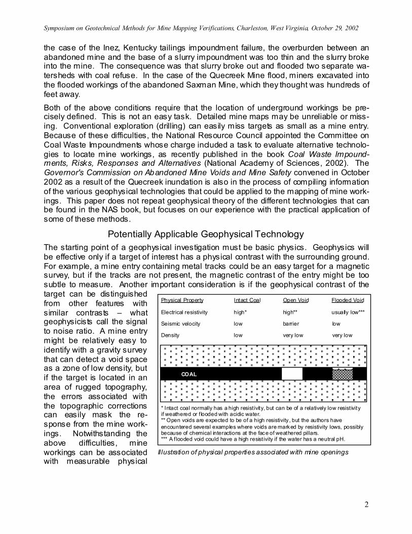
Potentially Applicable Geophysical Technology The starting point of a geophysical investigation must be basic physics. Geophysics will be effective only if a target of interest has a physical contrast with the surrounding ground. For example, a mine entry containing metal tracks could be an easy target for a magnetic survey, but if the tracks are not present, the magnetic contrast of the entry might be too subtle to measure. Another important consideration is if the geophysical contrast of the target can be distinguished from other features with similar contrasts – what geophysicists call the signal to noise ratio. A mine entry might be relatively easy to identify with a gravity survey that can detect a void space as a zone of low density, but if the target is located in an area of rugged topography, the errors associated with the topographic corrections can easily mask the re-sponse from the mine work-ings. Notwithstanding the above difficulties, mine workings can be associated with measurable physical
Physical Property Intact Coal Open Void Flooded Void
Electrical resistivity high* high** usually low***
Seismic velocity low barrier low
Density low very low very low
COAL
* Intact coal normally has a high resist ivity, but can be of a relatively low resist ivityif weathered or f looded with acidic water.** Open voids are expected to be of a high resistivity , but the authors haveencountered several examples where voids are marked by resistivity lows, possiblybecause of chemical interactions at the face of weathered pillars.*** A f looded void could have a high resist ivity if the water has a neutral pH.
Il lustration of physical properties associated with mine openings
Symposium on Geotechnical Methods for Mine Mapping Verifications, Charleston, West Virginia, October 29, 2002
3
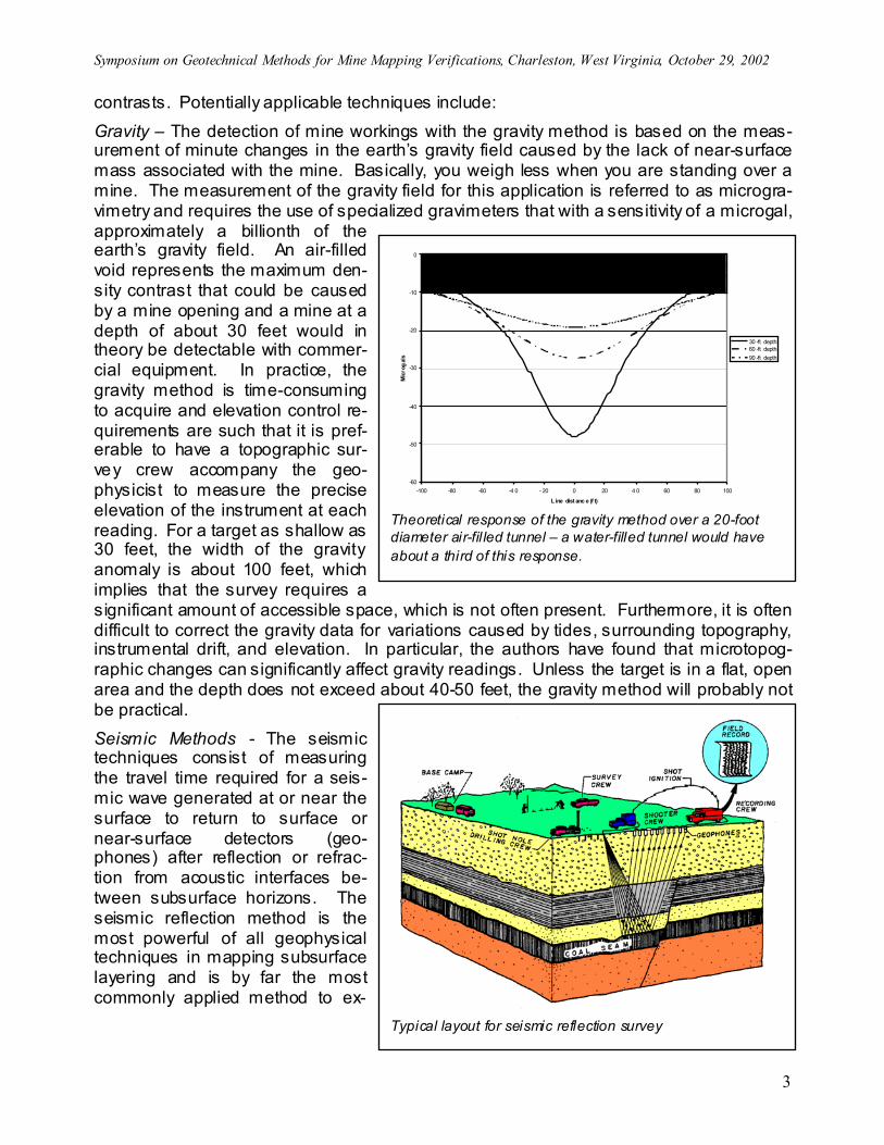
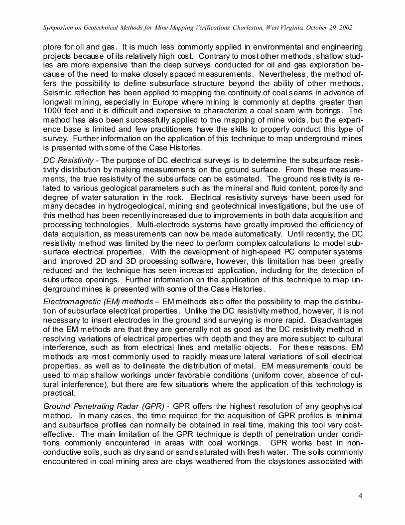
contrasts. Potentially applicable techniques include: Gravity – The detection of mine workings with the gravity method is based on the meas-urement of minute changes in the earth’s gravity field caused by the lack of near-surface mass associated with the mine. Basically, you weigh less when you are standing over a mine. The measurement of the gravity field for this application is referred to as microgra-vimetry and requires the use of specialized gravimeters that with a sensitivity of a microgal, approximately a billionth of the earth’s gravity field. An air-filled void represents the maximum den-sity contrast that could be caused by a mine opening and a mine at a depth of about 30 feet would in theory be detectable with commer-cial equipment. In practice, the gravity method is time-consuming to acquire and elevation control re-quirements are such that it is pref-erable to have a topographic sur-vey crew accompany the geo-physicist to measure the precise elevation of the instrument at each reading. For a target as shallow as 30 feet, the width of the gravity anomaly is about 100 feet, which implies that the survey requires a significant amount of accessible space, which is not often present. Furthermore, it is often difficult to correct the gravity data for variations caused by tides, surrounding topography, instrumental drift, and elevation. In particular, the authors have found that microtopog-raphic changes can significantly affect gravity readings. Unless the target is in a flat, open area and the depth does not exceed about 40-50 feet, the gravity method will probably not be practical. Seismic Methods - The seismic techniques consist of measuring the travel time required for a seis-mic wave generated at or near the surface to return to surface or near-surface detectors (geo-phones) after reflection or refrac-tion from acoustic interfaces be-tween subsurface horizons. The seismic reflection method is the most powerful of all geophysical techniques in mapping subsurface layering and is by far the most commonly applied method to ex-
-60
-50
-40
-30
-20
-10
0
-100 -80 -60 -4 0 - 20 0 20 4 0 60 80 100
L ine dist anc e (f t)
Mic
rog
als
30 -ft depth60 -ft depth90 -ft depth
Approximate limit of detect ion with grav ity method
Theoretical response of the gravity method over a 20-foot diameter air-fil led tunnel – a water-filled tunnel would have about a third of this response.
Typical layout for seismic reflection survey
Symposium on Geotechnical Methods for Mine Mapping Verifications, Charleston, West Virginia, October 29, 2002
4
plore for oil and gas. It is much less commonly applied in environmental and engineering projects because of its relatively high cost. Contrary to most other methods, shallow stud-ies are more expensive than the deep surveys conducted for oil and gas exploration be-cause of the need to make closely spaced measurements. Nevertheless, the method of-fers the possibility to define subsurface structure beyond the ability of other methods. Seismic reflection has been applied to mapping the continuity of coal seams in advance of longwall mining, especially in Europe where mining is commonly at depths greater than 1000 feet and it is difficult and expensive to characterize a coal seam with borings. The method has also been successfully applied to the mapping of mine voids, but the experi-ence base is limited and few practitioners have the skills to properly conduct this type of survey. Further information on the application of this technique to map underground mines is presented with some of the Case Histories. DC Resistivity - The purpose of DC electrical surveys is to determine the subsurface resis-tivity distribution by making measurements on the ground surface. From these measure-ments, the true resistivity of the subsurface can be estimated. The ground resistivity is re-lated to various geological parameters such as the mineral and fluid content, porosity and degree of water saturation in the rock. Electrical resistivity surveys have been used for many decades in hydrogeological, mining and geotechnical investigations, but the use of this method has been recently increased due to improvements in both data acquisition and processing technologies. Multi-electrode systems have greatly improved the efficiency of data acquisition, as measurements can now be made automatically. Until recently, the DC resistivity method was limited by the need to perform complex calculations to model sub-surface electrical properties. With the development of high-speed PC computer systems and improved 2D and 3D processing software, however, this limitation has been greatly reduced and the technique has seen increased application, including for the detection of subsurface openings. Further information on the application of this technique to map un-derground mines is presented with some of the Case Histories. Electromagnetic (EM) methods – EM methods also offer the possibility to map the distribu-tion of subsurface electrical properties. Unlike the DC resistivity method, however, it is not necessary to insert electrodes in the ground and surveying is more rapid. Disadvantages of the EM methods are that they are generally not as good as the DC resistivity method in resolving variations of electrical properties with depth and they are more subject to cultural interference, such as from electrical lines and metallic objects. For these reasons, EM methods are most commonly used to rapidly measure lateral variations of soil electrical properties, as well as to delineate the distribution of metal. EM measurements could be used to map shallow workings under favorable conditions (uniform cover, absence of cul-tural interference), but there are few situations where the application of this technology is practical. Ground Penetrating Radar (GPR) - GPR offers the highest resolution of any geophysical method. In many cases, the time required for the acquisition of GPR profiles is minimal and subsurface profiles can normally be obtained in real time, making this tool very cost-effective. The main limitation of the GPR technique is depth of penetration under condi-tions commonly encountered in areas with coal workings. GPR works best in non-conductive soils, such as dry sand or sand saturated with fresh water. The soils commonly encountered in coal mining area are clays weathered from the claystones associated with
Symposium on Geotechnical Methods for Mine Mapping Verifications, Charleston, West Virginia, October 29, 2002
5
the sedimentary sequences that include the coal and these soils severely restrict the effec-tive penetration of the radar waves. Nevertheless, GPR has been applied successfully to map mine voids and this paper offers one case history as an example. Magnetics – Coal has a low magnetic susceptibility when compared to most other rocks. A void in a coal seam, therefore, will not produce a significant disturbance to the earth’s natural magnetic field. Collapse structures above a coal seam, however, might produce measurable changes and it is likely that, barring other cultural interference, a modern magnetometer could detect old mine rails at a depth of several tens of feet. The main dis-advantage to the magnetometer is the likely presence of other cultural interference, espe-cially metal, commonly encountered in areas disturbed by man. Most geophysical techniques have been around for many years and the physics of detect-ing underground mines hasn’t changed. Basic interpretation strategies also haven’t changed, as interpretations are based on an understanding of the physics involved. What has changed is the ability of the geophysicist to gather data rapidly. Also, better com-puters and improved software have revolutionized the means by which data can be proc-essed and presented, resulting in improved interpretations. This paper presents five re-cent case histories where modern data acquisition and processing systems have been ap-plied in the detection of coal mine voids.
Case Histories Case History No. 1 – Locating Mine Workings at the Regency Park Subdivision, Plum Borough, Pennsylvania The Regency Park subdivision is located over shallow mine workings associated with the Plum Creek Mine operated in the late 19th and early 20th century. The subdivision has been the location of numerous foundation failures over the past several decades since the homes were constructed. This is not surprising, as many of the homes were constructed with 25 feet or less of overburden above the Pittsburgh Coal seam. This site is currently being remediated under the Abandoned Mine Land Reclamation Program directed by the Pennsylvania Department of Environmental Protection (PADEP). A portion of the subdivision was surveyed with the DC resistivity technique using the pole-dipole configuration with a multi-electrode automated measurement system manufactured by Iris Instruments. A pole-dipole survey is a type of DC resistivity measurement that uses three mobile electrodes and normally has one current electrode placed far enough from the others such that it can be considered to be at an “infinite” distance. In this case the “in-finite” electrode was located several hundred feet from the profile line. The results shown on the attached figures define a series of resistivity lows that bottom out at an elevation of 1140 feet MSL, consistent with the bottom of the Pittsburgh Coal seam as known from available mine maps and the results of borings drilled along the profile. Where borings were drilled within 5 feet of the profile, the resistivity lows were found to correspond to mine voids (partially collapsed) and the zones of relatively high resistivity between the lows was found to contain coal. The anomaly pattern and the results of the borings indicate that the resistivity lows and highs above an elevation of 1140 feet MSL
Symposium on Geotechnical Methods for Mine Mapping Verifications, Charleston, West Virginia, October 29, 2002
6
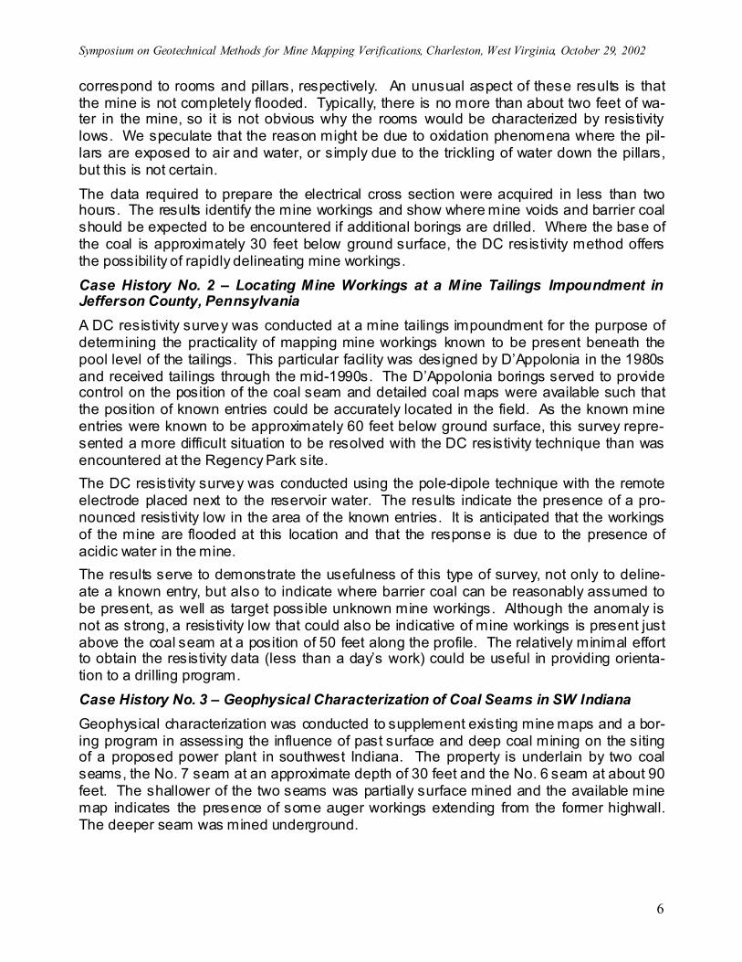
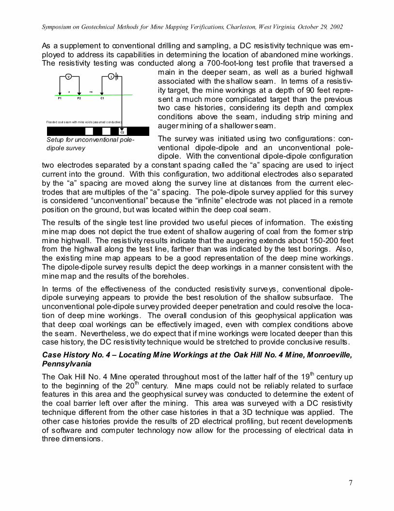
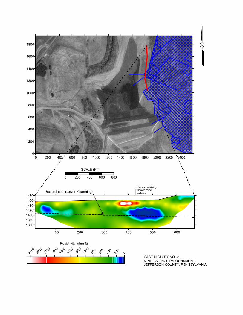
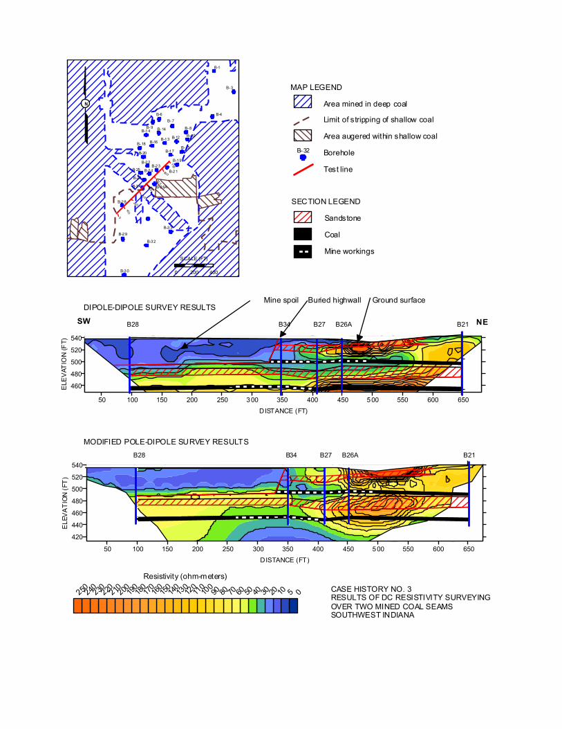
correspond to rooms and pillars, respectively. An unusual aspect of these results is that the mine is not completely flooded. Typically, there is no more than about two feet of wa-ter in the mine, so it is not obvious why the rooms would be characterized by resistivity lows. We speculate that the reason might be due to oxidation phenomena where the pil-lars are exposed to air and water, or simply due to the trickling of water down the pillars, but this is not certain. The data required to prepare the electrical cross section were acquired in less than two hours. The results identify the mine workings and show where mine voids and barrier coal should be expected to be encountered if additional borings are drilled. Where the base of the coal is approximately 30 feet below ground surface, the DC resistivity method offers the possibility of rapidly delineating mine workings. Case History No. 2 – Locating Mine Workings at a Mine Tailings Impoundment in Jefferson County, Pennsylvania A DC resistivity survey was conducted at a mine tailings impoundment for the purpose of determining the practicality of mapping mine workings known to be present beneath the pool level of the tailings. This particular facility was designed by D’Appolonia in the 1980s and received tailings through the mid-1990s. The D’Appolonia borings served to provide control on the position of the coal seam and detailed coal maps were available such that the position of known entries could be accurately located in the field. As the known mine entries were known to be approximately 60 feet below ground surface, this survey repre-sented a more difficult situation to be resolved with the DC resistivity technique than was encountered at the Regency Park site. The DC resistivity survey was conducted using the pole-dipole technique with the remote electrode placed next to the reservoir water. The results indicate the presence of a pro-nounced resistivity low in the area of the known entries. It is anticipated that the workings of the mine are flooded at this location and that the response is due to the presence of acidic water in the mine. The results serve to demonstrate the usefulness of this type of survey, not only to deline-ate a known entry, but also to indicate where barrier coal can be reasonably assumed to be present, as well as target possible unknown mine workings. Although the anomaly is not as strong, a resistivity low that could also be indicative of mine workings is present just above the coal seam at a position of 50 feet along the profile. The relatively minimal effort to obtain the resistivity data (less than a day’s work) could be useful in providing orienta-tion to a drilling program. Case History No. 3 – Geophysical Characterization of Coal Seams in SW Indiana Geophysical characterization was conducted to supplement existing mine maps and a bor-ing program in assessing the influence of past surface and deep coal mining on the siting of a proposed power plant in southwest Indiana. The property is underlain by two coal seams, the No. 7 seam at an approximate depth of 30 feet and the No. 6 seam at about 90 feet. The shallower of the two seams was partially surface mined and the available mine map indicates the presence of some auger workings extending from the former highwall. The deeper seam was mined underground.
Symposium on Geotechnical Methods for Mine Mapping Verifications, Charleston, West Virginia, October 29, 2002
7
As a supplement to conventional drilling and sampling, a DC resistivity technique was em-ployed to address its capabilities in determining the location of abandoned mine workings. The resistivity testing was conducted along a 700-foot-long test profile that traversed a
main in the deeper seam, as well as a buried highwall associated with the shallow seam. In terms of a resistiv-ity target, the mine workings at a depth of 90 feet repre-sent a much more complicated target than the previous two case histories, considering its depth and complex conditions above the seam, including strip mining and auger mining of a shallower seam. The survey was initiated using two configurations: con-ventional dipole-dipole and an unconventional pole-dipole. With the conventional dipole-dipole configuration
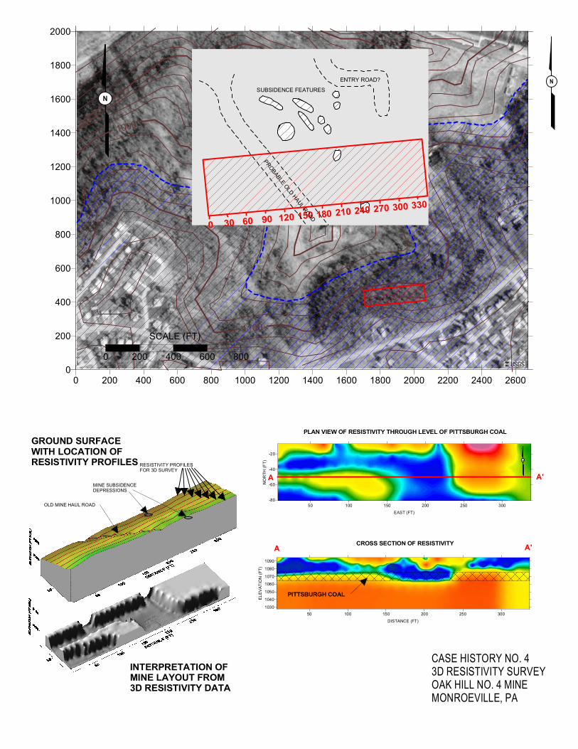
two electrodes separated by a constant spacing called the “a” spacing are used to inject current into the ground. With this configuration, two additional electrodes also separated by the “a” spacing are moved along the survey line at distances from the current elec-trodes that are multiples of the “a” spacing. The pole-dipole survey applied for this survey is considered “unconventional” because the “infinite” electrode was not placed in a remote position on the ground, but was located within the deep coal seam. The results of the single test line provided two useful pieces of information. The existing mine map does not depict the true extent of shallow augering of coal from the former strip mine highwall. The resistivity results indicate that the augering extends about 150-200 feet from the highwall along the test line, farther than was indicated by the test borings. Also, the existing mine map appears to be a good representation of the deep mine workings. The dipole-dipole survey results depict the deep workings in a manner consistent with the mine map and the results of the boreholes. In terms of the effectiveness of the conducted resistivity surveys, conventional dipole-dipole surveying appears to provide the best resolution of the shallow subsurface. The unconventional pole-dipole survey provided deeper penetration and could resolve the loca-tion of deep mine workings. The overall conclusion of this geophysical application was that deep coal workings can be effectively imaged, even with complex conditions above the seam. Nevertheless, we do expect that if mine workings were located deeper than this case history, the DC resistivity technique would be stretched to provide conclusive results. Case History No. 4 – Locating Mine Workings at the Oak Hill No. 4 Mine, Monroeville, Pennsylvania The Oak Hill No. 4 Mine operated throughout most of the latter half of the 19th century up to the beginning of the 20th century. Mine maps could not be reliably related to surface features in this area and the geophysical survey was conducted to determine the extent of the coal barrier left over after the mining. This area was surveyed with a DC resistivity technique different from the other case histories in that a 3D technique was applied. The other case histories provide the results of 2D electrical profiling, but recent developments of software and computer technology now allow for the processing of electrical data in three dimensions.
V I
a na
P1 C1P2
I
C2
Flooded coal s eam with mine voids (ass umed c onductive)
Setup for unconventional pole-dipole survey
Symposium on Geotechnical Methods for Mine Mapping Verifications, Charleston, West Virginia, October 29, 2002
8
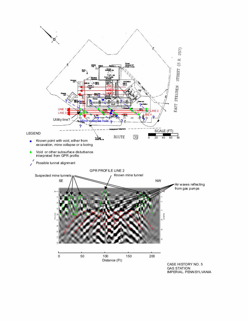
The survey was conducted along seven parallel profiles with the DC resistivity technique using the pole-dipole configuration and placing the electrode in moist soil at the base of a distant sinkhole. The data were then processed as a single block of data from which it was possible to extract both horizontal and vertical slices of the data set. The slice of resistivity data through the level of the Pittsburgh Coal seam depicts a pattern that appears to relate to rooms and pillars. Further analysis of the electrical cross sections through the coal pro-vide additional evidence of the relationship of the electrical measurements to the old mine. When depicted as a 3D block, the interpreted results show where barrier coal is present. The data do not define what the mine is filled with. Similar to the Regency Park example, the mined-out area is a marked resistivity low. Subsidence craters at the ground surface indicate that the edge of the block of barrier coal in the eastern part of the survey area is an open entry. Although the remainder of the mine could also be a void, it could also be filled with gob that would also be expected to exhibit a low resistivity. This survey is depicts another example of how the results of a geophysical survey could help define the scope of a drilling program. Borings could easily be targeted using the geophysical results to increase the probability of encountering mine workings. Conversely, the results also serve to identify the continuity of zones where mine workings are not ex-pected to be present. Case History No. 5 – Locating Mine Workings with the GPR Technique at a Gas Sta-tion in Imperial, Pennsylvania The gas station surveyed in Imperial, Pennsylvania was originally constructed in the 1960s and reconstructed in 1996. In the process of creating land suitable for development, a bench was cut in a hillside, which inadvertently placed the structures only a few feet above the top of the Pittsburgh Coal seam. In the summer of 2001, approximately 30 years after the station began operation, a small opening appeared in the asphalt pavement through which a mine tunnel could be observed and mapped to a limited degree. D’Appolonia was contracted to determine the extent of the known mine opening and to determine if any other openings could be present. This case history represents the unusual situation where the coal workings were in the range of penetration for the GPR system. Although the roof material was a weathered claystone, normally a difficult medium for the GPR method, the top of the visible mine tun-nel was only four feet below ground surface. The survey was conducted with both 50 and 200 MHz antennas with a RAMAC GPR sys-tem. The 200 MHz antenna did not have a sufficient depth of penetration so a 50 MHz an-tenna was employed. The 50 MHz antenna provided an adequate depth of penetration (to approximately 10 feet) but was also susceptible to reflections from surface objects. Spe-cifically, the five gas pump islands represented a significant interference. Nevertheless, it did prove possible to image the known mine tunnel, as well as other suspected tunnels. The centerpoints of the known and suspected tunnels were plotted on a map of the service station and were found to define a consistent N-S alignment. The service station has been subsequently remediated by D’Appolonia. The reflections identified from the GPR survey did prove to be tunnels, although the GPR method did not distinguish if the tunnels were open or filled with gob.
Symposium on Geotechnical Methods for Mine Mapping Verifications, Charleston, West Virginia, October 29, 2002
9
Case History No. 6 – Locating Deep Mine Workings for Methane Extraction with the S-Wave Seismic Reflection Technique in Illinois A short (235-foot long) S-wave profile was obtained by Bay Geophysical Associates over an abandoned coal mine to detect mine openings that would be suitable targets for the in-stallation of methane extraction wells. Two boreholes had been drilled on the basis of an old mine map, without encountering the mine. An S-wave survey was selected to detect the mine voids because S-waves will not transmit through a void whereas P-waves, the type of seismic wave normally associated with seismic exploration, can be transmitted through a void space. Mine voids should therefore appear as a “bright spot” on the S-Wave record. The S-wave survey was conducted with the following equipment setup and field parame-ters: ● Bison 9048 seismograph, 48 channels ● Oyo Geospace 40 Hz horizontal geophones ● Source: hammer-struck railroad tie ● Trace interval: 2.5 feet ● Coverage: 48 fold The data were processed by a commercial processing firm following steps routinely fol-lowed to process oil and gas exploration S-wave data. The coal seam could be related to the seismic reflections and an area where the floor of the mine had a relatively low ampli-tude reflection compared to the roof was targeted for an exploratory boring. Mine workings were encountered by that boring at a depth of close to 700 feet, as predicted. Case History No. 7 – S-Wave Seismic Survey over Abandoned Coal Mine Workings, Des Moines, Iowa Control borings at a proposed construction site in Des Moines, Iowa encountered a col-lapsed mine in one borehole and coal was found to be missing in several other borings. The attached figure shows a high-resolution S-wave seismic reflection seismic profile that crosses a control boring that encountered a void with wood cuttings (from timbers used to support the mine). This profile was obtained by a high-frequency S-wave vibrator devel-oped by Bay Geophysical Associates specifically to be able to measure high-resolution profiles for engineering application to a maximum depth of approximately 300 feet. The coal seam of interest in this case is present at a depth of between about 50 – 60 feet. The profile shows a break in the reflection from the coal where the control boring encountered mine workings. The seismic profile also shows a discontinuity of the coal seam between stations 60 and 110. When several seismic profiles were correlated, it was found that this break in the coal seam was actually a natural channel cut through the coal. The geotechnical borings that had not encountered the coal were found to have been drilled through this natural channel fill. Abandoned mine workings, such as penetrated by the single geotechnical boring and also visible on the seismic reflection profile, were not found to be a problem over most of the construction site.
Symposium on Geotechnical Methods for Mine Mapping Verifications, Charleston, West Virginia, October 29, 2002
10
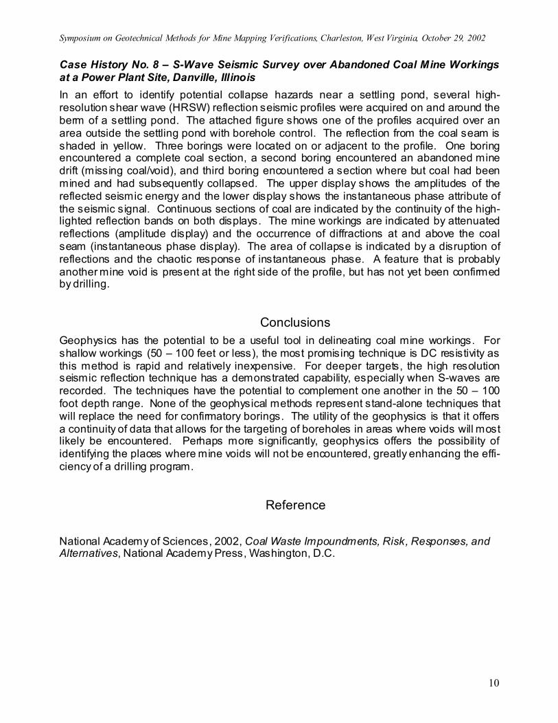
Case History No. 8 – S-Wave Seismic Survey over Abandoned Coal Mine Workings at a Power Plant Site, Danville, Illinois In an effort to identify potential collapse hazards near a settling pond, several high-resolution shear wave (HRSW) reflection seismic profiles were acquired on and around the berm of a settling pond. The attached figure shows one of the profiles acquired over an area outside the settling pond with borehole control. The reflection from the coal seam is shaded in yellow. Three borings were located on or adjacent to the profile. One boring encountered a complete coal section, a second boring encountered an abandoned mine drift (missing coal/void), and third boring encountered a section where but coal had been mined and had subsequently collapsed. The upper display shows the amplitudes of the reflected seismic energy and the lower display shows the instantaneous phase attribute of the seismic signal. Continuous sections of coal are indicated by the continuity of the high-lighted reflection bands on both displays. The mine workings are indicated by attenuated reflections (amplitude display) and the occurrence of diffractions at and above the coal seam (instantaneous phase display). The area of collapse is indicated by a disruption of reflections and the chaotic response of instantaneous phase. A feature that is probably another mine void is present at the right side of the profile, but has not yet been confirmed by drilling.
Conclusions Geophysics has the potential to be a useful tool in delineating coal mine workings. For shallow workings (50 – 100 feet or less), the most promising technique is DC resistivity as this method is rapid and relatively inexpensive. For deeper targets, the high resolution seismic reflection technique has a demonstrated capability, especially when S-waves are recorded. The techniques have the potential to complement one another in the 50 – 100 foot depth range. None of the geophysical methods represent stand-alone techniques that will replace the need for confirmatory borings. The utility of the geophysics is that it offers a continuity of data that allows for the targeting of boreholes in areas where voids will most likely be encountered. Perhaps more significantly, geophysics offers the possibility of identifying the places where mine voids will not be encountered, greatly enhancing the effi-ciency of a drilling program.
Reference
National Academy of Sciences, 2002, Coal Waste Impoundments, Risk, Responses, and Alternatives, National Academy Press, Washington, D.C.

0 100 200 300 400 500 6000
50
100
150
200
250
300
350
400
450
0 50 100 150 200 250
20 40 60 80 100 120 140 160 180 200 220 240 260 280 300 320
N
38B 40A40B
41A
38B 40A 40B 41A
Void
Coal
SCALE (FT)
CASE HISTORY NO. 1REGENCY PARK SUBDIVISIONPLUM BOROUGH, PENNSYLVANIA
11601150114011301120
LEGEND
100300500700900
1100
1300
1500
1700
1900
2100
2300
2500
ELE
V. M
SL (F
T)
DISTANCE (FT)
BASE OF PITTSBURGHCOAL
BASE OF SOIL
Resistivity (ohm-ft)
39B 41B
100 200 300 400 500 600
1360138014001420144014601480
0 200 400 600 800 1000 1200 1400 1600 1800 2000 2200 24000
200
400
600
800
1000
1200
1400
1600
1800
0 200 400 600 800
SCALE (FT)
0200
400
600
800
1000
1200
1400
1600
1800
2000
2200
2400
N
Base of coal (Lower Kittanning)
Resistivity (ohm-ft)
CASE HISTORY NO. 2MINE TAILINGS IMPOUNDMENTJEFFERSON COUNTY, PENNSYLVANIA
Zone containingknown mineentries
50 100 150 200 250 300 350 400 450 500 550 600 650DISTANCE (FT)
460
480
500
520
540
ELE
VAT
ION
(FT)
SW NE
50 100 150 200 250 300 350 400 450 500 550 600 650DISTANCE (FT)
420
440
460
480
500
520
540
ELE
VA
TIO
N (
FT)
B21B26AB27B34B28
B21B26AB27B34B28
05102030405060708090100
110
120
130
140
150
160
170
180
190
200210220230240250Resistivity (ohm-meters)
SECTION LEGEND
Sandstone
Coal
Mine workings
DIPOLE-DIPOLE SURVEY RESULTS
MODIFIED POLE-DIPOLE SURVEY RESULTS
B-28
B-25
B-34
B-27
B-24B-23
B-22
B-21
B-20
B-18 B-16B-13
B-14 B-14B-9
B-6B-7
B-12
B-8
B-4
B-10
B-3
B-1
B-15B-17
B-19
B-33
B-32
B-29
B-30
MAP LEGEND
Area mined in deep coal
Limit of stripping of shallow coal
Area augered within shallow coal
Borehole
Test line
B-32
0
100
20 0
30 0
400
50 0
60 0
700
B-26A
SCALE (FT)
0 200 400
N
Mine spoil Buried highwall Ground surface
CASE HISTORY NO. 3RESULTS OF DC RESISTIVITY SURVEYINGOVER TWO MINED COAL SEAMSSOUTHWEST INDIANA
0 200 400 600 800 1000 1200 1400 1600 1800 2000 2200 2400 26000
200
400
600
800
1000
1200
1400
1600
1800
2000
N
1100
1000
CASE HISTORY NO. 43D RESISTIVITY SURVEYOAK HILL NO. 4 MINEMONROEVILLE, PA
0 30 60 90 120 150 180 210 270 300 330
PROBABLE OLD HAUL ROAD
ENTRY ROAD?
SUBSIDENCE FEATURES
240
0 200 400 600 800
SCALE (FT)
N
50 100 150 200 250 300DISTANCE (FT)
1030
1040
1050
1060
1070
1080
1090
ELEV
ATIO
N (F
T)
50 100 150 200 250 300EAST (FT)
-80
-60
-40
-20
NO
RTH
(FT)
A A'
A'A
PLAN VIEW OF RESISTIVITY THROUGH LEVEL OF PITTSBURGH COAL
CROSS SECTION OF RESISTIVITY
N
PITTSBURGH COAL
OLD MINE HAUL ROAD
MINE SUBSIDENCEDEPRESSIONS
RESISTIVITY PROFILESFOR 3D SURVEY
GROUND SURFACEWITH LOCATION OFRESISTIVITY PROFILES
INTERPRETATION OFMINE LAYOUT FROM3D RESISTIVITY DATA
-190 -170 -150 -130 -110 -90 -70 -50 -30 -10
0 20 40 60 80
SCALE (FT)
LINE 1 LINE 2LINE 4LINE 3
LINE 5LINE 6LINE 7
LIN
E 8
Mine collapse hole
LEGEND
Known point with void, either from excavation, mine collapse or a boring
Void or other subsurface disturbance interpreted from GPR profile
Possible tunnel alignment
Utility line?
?
?????
??
?? ?
?
0 50 100 150 200
Known mine tunnel
Distance (Ft)
GPR PROFILE LINE 2
SE NWSuspected mine tunnels
Air waves reflectingfrom gas pumps
CASE HISTORY NO. 5GAS STATION IMPERIAL. PENNSYLVANIA
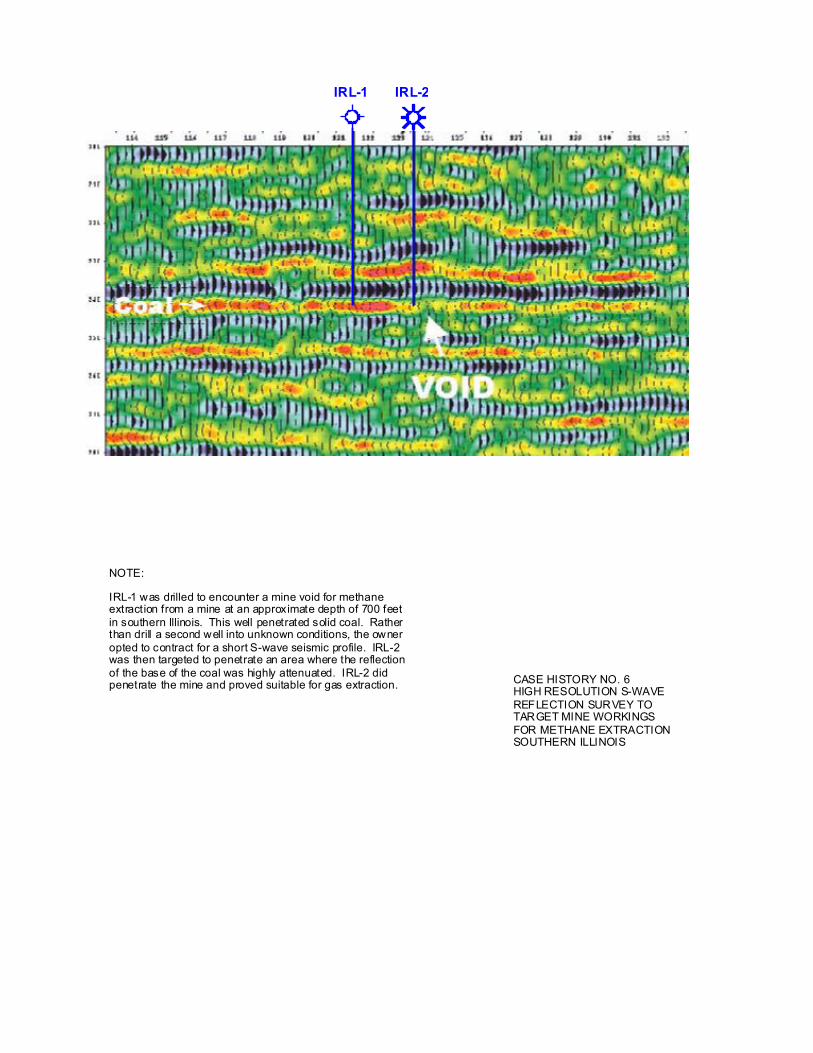
IRL-1 IRL-2
NOTE:
IRL-1 was drilled to encounter a mine void for methaneextraction from a mine at an approximate depth of 700 feetin southern Illinois. This well penetrated solid coal. Ratherthan drill a second well into unknown conditions, the owneropted to contract for a short S-wave seismic profile. IRL-2was then targeted to penetrate an area where the reflectionof the base of the coal was highly attenuated. IRL-2 didpenetrate the mine and proved suitable for gas extraction. CASE HISTORY NO. 6
HIGH RESOLUTION S-WAVEREFLECTION SURVEY TOTARGET MINE WORKINGSFOR METHANE EXTRACTIONSOUTHERN ILLINOIS
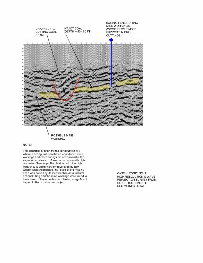
BORING PENETRATINGMINE WORKINGS(WOOD FROM TIMBERSUPPORT IN DRILLCUTTINGS)
INTACT COAL(DEPTH ~ 50 - 60 FT)
CHANNEL FILLCUTTING COALSEAM
POSSIBLE MINEWORKING
NOTE:
This example is taken from a construction sitewhere a boring had penetrated abandoned mineworkings and other borings did not encounter theexpected coal seam. Based on an unusually highresolution S-wave profile obtained with the highfrequency S-wave vibrator developed by Bay Geophysical Associates, the "case of the missingcoal" was solved by its identification as a naturalchannel filling and the mine workings were found tohave been of limited extent, not having a significantimpact to the construction project.
CASE HISTORY NO. 7HIGH RESOLUTION S-WAVEREFLECTION SURVEY FROMCONSTRUCTION SITEDES MOINES, IOWA
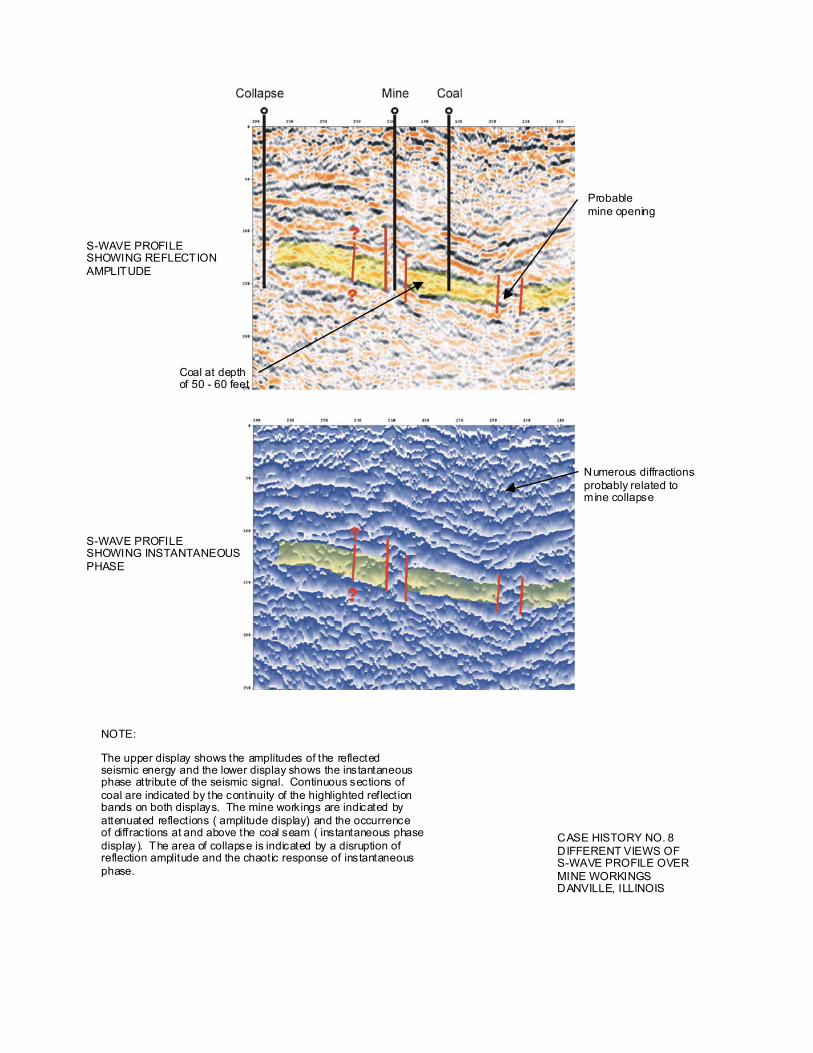
S-WAVE PROFILESHOWING REFLECTIONAMPLITUDE
S-WAVE PROFILESHOWING INSTANTANEOUSPHASE
CASE HISTORY NO. 8DIFFERENT VIEWS OF S-WAVE PROFILE OVERMINE WORKINGSDANVILLE, ILLINOIS
Probablemine opening
NOTE:
The upper display shows the amplitudes of the reflectedseismic energy and the lower display shows the instantaneousphase attribute of the seismic signal. Continuous sections ofcoal are indicated by the continuity of the highlighted reflectionbands on both displays. The mine workings are indicated byattenuated reflections ( amplitude display) and the occurrenceof diffractions at and above the coal seam ( instantaneous phasedisplay). The area of collapse is indicated by a disruption ofreflection amplitude and the chaotic response of instantaneousphase.
Numerous diffractionsprobably related tomine collapse
Coal at depthof 50 - 60 feet