Surface and Inner Deformation during Shape Rolling …12375/FULLTEXT01.pdf · Surface and Inner...
24
Surface and Inner Deformation during Shape Rolling of High Speed Steels Kristina Nordén Royal Institute of Technology School of Industrial Engineering and Management Material Science and Engineering Division of Mechanical Metallurgy SE-100 44 Stockholm, Sweden
Transcript of Surface and Inner Deformation during Shape Rolling …12375/FULLTEXT01.pdf · Surface and Inner...

Surface and Inner Deformation during Shape Rolling of High Speed Steels
Kristina Nordén
Royal Institute of Technology School of Industrial Engineering and Management
Material Science and Engineering Division of Mechanical Metallurgy
SE-100 44 Stockholm, Sweden

Akademisk avhandling som med tillstånd av Kungl Tekniska Högskolan framlägges till offentlig granskning för avläggande av teknisk licentiatexamen tisdagen den 15 maj 2007 kl. 11.00 vid Institutionen för Materialvetenskap, Kungl Tekniska Högskolan, konferensrummet K408, 4:e våningen, Brinellvägen 23, Stockholm. Fakultetsopponent är Jan-Olov Perä, MEFOS, Box 812, 971 25 Luleå. ISBN 978-91-7178-649-4 ISRN KTH/MSE--07/17--SE+MEK/AVH © Kristina Nordén, April 2007
ii

Abstract Shape rolling is a common manufacturing process used to produce long products i.e. bars and wire. One of the problems that might occur during rolling is defect formation leading to rejection of the finished product. This work is a step towards a better understanding of the evolution of some of these defects. The evolution and reduction of cracks during shape rolling is studied in this thesis. To accomplish this, artificial longitudinal cracks are machined along bars of high speed steel. The cracks are positioned at different sites evenly distributed along the periphery in intervals of 45°. Some of the cracks are left open and some are filled with carbon or stainless steel welds. FE simulations are performed using the commercial code MSC.Marc and the results from the simulations are compared with experimental ones. Generally, simulations predict less reduction than observed experimentally. For most positions, the cracks tend to reduce most effectively followed by carbon steel welds and stainless steel welds. To evaluate the inner deformation of a cross section during shape rolling in an oval-round-oval-round series, sample bars of M2 high speed steel are prepared with grids made up by stainless steel wires. After collecting samples after each pass, they are X-rayed to create an image of the grid. The deformation of the wires can favorably be described by FE simulations of a bar originally rotated 10° when entering the first pass. The results suggest that the simulations describe the deformation during shape rolling well. Keywords: FEM, wire-rod rolling, shape rolling, high speed steel, inner deformation, deformation behavior, artificial cracks, surface layer deformation
iii

iv

Preface The work presented in this thesis was carried out Dalarna University in Borlänge, Sweden and most of the experiments were performed at Erasteel Kloster AB in Långshyttan, Sweden. The final writing of the thesis was performed at Royal Institute of Technology, Stockholm. The financial support was provided by the Swedish Steel Producer’s Association (Jernkontoret), the Swedish Knowledge Foundation (KK-stiftelsen) and Erasteel Kloster AB. I would like to express my gratitude to my supervisor Stefan Jonsson for all his guidance and support during the work with this thesis. To all my colleagues both at Dalarna University and at Erasteel in Långshyttan, thank you for all your help. I am especially grateful to Mårten Fexby at Erasteel, for all interesting discussions and advice. Finally, I want to thank my family and friends for their encouragement and support, I never would have managed without it and especially Mikael for bearing with me. Kristina Nordén Stockholm, April 2007
v

vi
Thesis This thesis includes the following two appended papers: Paper 1 A study of Surface Deformation during Wire-Rod Rolling of High Speed Steels using Experimental and Computational Techniques K. Nordén S. Jonsson Accepted for publication in Steel Research International Paper 2 Experimental and Numerical Study of Inner Deformation during Shape Rolling of an M2 High Speed Steel K. Nordén S. Jonsson Manuscript to be submitted to an international journal
vii

viii

Table of contents 1. INTRODUCTION 1
1.1. OBJECTIVE OF THE WORK 1 1.2. SHAPE ROLLING 1
2. DEFECTS IN WIRE-ROD ROLLING 2 2.1. FINS 2 2.2. LAPS 2 2.3. SHELLS 3 2.4. CRACKS, LONGITUDINAL AND TRANSVERSE 3 2.5. END CRACKING 4
3. HIGH SPEED STEEL, HSS 4 3.1. BACKGROUND 4 3.2. PROPERTIES 5
4. EXPERIMENTAL TECHNIQUES 7 4.1. LONGITUDINAL SURFACE DEFECTS 7 4.2. INNER DEFORMATION 9 4.3. FE-SIMULATIONS 9
5. RESULTS AND DISCUSSION 10 6. CONCLUSIONS 13
6.1. SURFACE DEFORMATION 13 6.2. INNER DEFORMATION 13
7. REFERENCES 14
APPENDED PAPERS
ix

x

1 Introduction
1.1 Objective of the work The objective of this work was to experimentally determine the inner deformation and the surface deformation of a bar during wire-rod rolling and compare the results with simulations using FEM. This information could help in the work towards the reduction or elimination of the amount of surface defects on the finished wire and provide better knowledge on the inner deformation behavior of a bar during shape rolling.
1.2 Shape rolling Shape rolling is a manufacturing process used to produce wire and bars, and can also be used to manufacture products with a more complicated cross section. The process normally starts with heating of the billet, followed by rolling in a roughing mill, which is commonly reversible, rolling in an intermediate mill and in a finishing mill, possible followed by some kind of heat treatment. For steel qualities that can be deformed at higher speeds without problems, some of the last passes can be performed in a wire block. The difference between shape rolling and hot strip rolling is that instead of flat rolls, the rolls have grooves of different shapes, see Figure 1.
Figure 1. Example of a roll with grooves, used for shape-rolling.
Rolling the billet in these grooves provide deformation around the entire cross section which gives a more complicated stress-state. The billet is rotated between each pass to enable deformation around the perimeter of the billet. The grooves can have several different geometries, like square, diamond, round, oval, box etc. Roll-pass design, which decides the shape, size and combination of the grooves, is a complex work. However, using an optimal roll-pass design will result in defect free products with correct dimension. In the work of improving the roll-pass design finite element simulations are a useful tool. Using FEM can provide a picture of the deformation of the billet and risks for defects could possibly be detected. A drawback of FE is, however, that the simulations generally are quite time consuming.
1

2 Defects in wire-rod rolling Most of the defects in wire-rod rolling can be detected either by the naked eye or with anon-destructive test, for example an eddy current test. This method works with a current screening the wire, detecting changes in the current where a defect is present. A description and some of the possible sources for the most common types of defects are presented more thoroughly in the following text. Defects that are caused by incorrect rolling practices are not described in this work.
2.1 Fins Fins usually occur when a groove is overfilled, [1]. Overfilling can occur when the rolls are not set properly or the reduction is too large, see Figure 2. If there is only a fin on one side of the cross-section, the guides might not be centered or the wire not rotating properly. Fins usually occur along the entire wire. They can also be caused by pipe in the ingot, large segregation or inclusions.
Figure 2. Picture of fins on a sample after pass 14.
2.2 Laps Laps always run longitudinally on the wire and usually arise when fins are folded and rolled into the surface of the wire in the subsequent roll passes, see Figure 3. They can be quite long and of uniform shape. Too large temperature changes causing non-uniform spread can also cause laps.
Figure 3. Picture of laps on a 9 mm wire.
2

2.3 Shells One of the most common surface defects during wire-rod rolling of HSS, shells, arise from overlapping material and can vary in both shape and size. The appearance is quite similar to laps, but shells are generally smaller and appear more sporadic. Shell can be caused by problems during casting, like splatter or boiling in the ingot. During rolling, coarse inclusions breaking near the surface can cause shells, as well as cracks later forming shells when rolled in the subsequent passes. See Figure 4 and Figure 5 for samples of shells.
Figure 4. Picture of shell on a 9 mm wire.
Figure 5. Cross section of a 9 mm wire showing a shell in 50x magnification.
2.4 Cracks, longitudinal and transverse Cracks can run both along the wire or transverse to it, see Figure 6-Figure 9. The cause for this type of surface defects could be a number of sources, occurring both in the melting shop and in the rolling mill. Stress cracks, skin holes, scab can occur during casting or solidification in the melting shop and after being elongated during the subsequent rolling appear as cracks. In the rolling mill, improper shape of the roll groove, worn-out roll surfaces, and guide scratches can be a cause of cracks.
Figure 6. Picture of longitudinal cracks on a 9 mm wire.
Figure 7. Cross section of a 9 mm wire showing longitudinal cracks in 100x magnification.
3

Figure 8. Picture of longitudinal cracks on a 9 mm wire.
Figure 9. Cross section of a 9 mm wire showing longitudinal cracks in 50x magnification.
2.5 End cracking End cracking is a quite common defect during wire-rod rolling of HSS. The consequence from this defect does not only include the loss of material but also the risk of damaging the rolls and the rolling mill [2]. For end cracking to occur there must be a stress state favoring cracks to propagate. This can appear due to piping during casting, segregation, presence of pores and blowholes and low material ductility. Another cause could be excessive temperatures leading to local melting causing loss in the strength of the material.
3 High speed steel, HSS
3.1 Background There is so far not a common international established and accepted definition of how high speed steel, HSS, differs from other steels [3]. In Sweden a definition concerning the composition exists: C – at least 0.6 %, Cr - normally present, W + Mo + V – at least 7 %. The definition in USA is: HSS for band saws is steel alloyed with Cr, V, Mo or W. The amount of alloys put together minus the amount of C should be at least 14 %. Another definition is that HSS should have an alloy content that allows it to retain its heat-resistance up to at least 1000° F while the cold-hardness at the same time is within the interval 60-66 HRC. Due to the difficulties to machine carbon steel with carbon steel, investigations with different alloys led to a steel presented by the Brit Mushet, in 1861. The steel contained 2 % C, 2.5 % Mn and 7 % W. The Mushet-steel did not give a great improvement in machinability, but it was an important step in the history of composition of steel, since it was one of the first alloyed steels. The Americans Taylor and White have been appointed the inventors of HSS. Their achievement was not a special composition but a methodology in the heat treatment which they developed in 1898. They discovered that the Mushet-steel obtained a considerately increased machinability when the austenitizing temperature was chosen higher then usually and high-temperature tempering was used [4]. They started using grades with a composition of 1.85 % C, 0.15 % Si, 0.30 % Mn, 3.8 % Cr and 8.0 % W and called it high-speed steel since it was possible to use at much faster cutting speeds than carbon steel. In 1906 the composition of HSS was changed to 0.67 % C, 4.0 % Cr, 0.3 % V and 18.9 % W. This grade of HSS, more commonly called 18-4-1, kept its dominating position during approximately 50 years.
4

Shortage of W during WW1 triggered development towards finding replacements for W and it was discovered by Taylor that 2 % W could be substituted with approximately 1 % Mo. However, this type of steel was considered inferior mostly due to its greater sensitivity to decarburization and decreased risk of overheating at austenitizing. The research on HSS continued between WW 1 and 2 and the new shortage of W during WW 2 stimulated the development and commercial acceptance of Mo and Mo-W grades. The increasing use of electrical furnace with better possibility to control temperature practically eliminated the risk of decarburization and overheating at austenitizing. The modifications on the composition are based on W and Mo contents, carbon content, the total content of carbide-forming elements (including W, Mo, Cr, and V) and Co content. Co is an important alloying element because of its ability to dissolve into the matrix and increase the hot hardness.
3.2 Properties One of the largest influences on the properties of HSS is the segregation of carbides. HSS is produced in electric or induction furnaces and then chill cast. The segregation in the centre of the ingot during solidification leads to a larger concentration of the alloying element in that part of the ingot, which results in poor alloy utilization. This effect leads to a very inhomogeneous material, with discrepancies in the mechanical properties along the cross section of the ingot. Different ways of eliminating the segregation effect has been attempted during the years:
- inoculation of the melt - controlled cast temperature and cast time - accelerated cooling - optimized shape and size of ingot
The ASP-process is a result of this struggle. It is a powder metallurgy technique, including hot-isostatic pressing (HIP) of rapidly solidified gas-atomised powder. During gas atomisation the melt is divided into small drops by powerful jets of nitrogen gas. These solidify at a very high rate, 100-1000ºC/s, not allowing the alloying elements time to segregate during the solidification. The powder is collected in a steel capsule which is welded after the air has been removed. After hipping of the ASP-powder, the microstructure of this material is fully homogeneous and the mechanical properties are isotropic. The difference in structure between conventional HSS and ASP can be seen in Figure 10 and Figure 11. Both samples have been magnified 150x. Figure 10 is the ingot structure of a conventional M2 HSS and the typical dendritical structure is obvious. Figure 11 is the as-hipped structure of ASP 2023 and the structure is quite fine-grained and very homogeneous.
5

Figure 10. Ingot structure of conventional M2 HSS. Magnification 150x.
Figure 11. As-hipped structure of powder metallurgical steel ASP 2023. Magnified 150x..
In Figure 12 and Figure 13 the bar has been rolled to a diameter of 16 mm, the magnification is still 150x and the samples have been collected longitudinal to the rolling direction. Figure 12 is conventional M2 HSS and the carbides have been aligned in bands, which can be observed in this sample. This is an effect of substantial hot work which spheroidizes the lamellar or fibrous eutectic carbides and aligns the carbides in bands. In the ASP 2023 sample in Figure 13 this phenomena can not be detected.
Figure 12. Sample from a 16 mm round bar of M2 conventional HSS. Magnification 150x.
Figure 13. Sample from a 16 mm round bar of powder metallurgical steel ASP 2023. Magnification 150x.
After hot working, annealing is required to produce a microstructure consisting of uniformly dispersed spheroidized carbides in a matrix of ferrite, which have a hardness low enough to be machinable [5]. When the tools have been machined into the required shape, austenitizing is performed for improved hardening. Austenitizing is accomplished by heating just below or at temperatures where melting initiates. This is a very critical step where the final alloy element partition between the austenitic matrix and the retained carbides occur, see Figure 14 for conventional M2 HSS and Figure 15 for ASP.
6

Figure 14. Conventional M2 HSS, as-hardened, hardening temperature 1220ºC, magnification 1500x.
Figure 15. Powder metallurgical steel ASP 2023, as-hardened, hardening temperature 1180ºC, magnification 1500x.
Tempering is the final critical heat treatment step for HSS, see Figure 16 for conventional M2 HSS and Figure 17 for ASP. Tempering can be performed 2 or 3 times to ensure that all retained austenite has been transformed into martensite. When comparing conventional HSS with ASP it can be noted that the carbides in ASP are finer, rounder and more evenly distributed in the sample. The difference in size of the carbides is not as large in ASP as it is in conventional HSS.
Figure 16. Conventional M2 HSS, hardening temperature 1220ºC, tempering 2x1 h at 560ºC, magnification 1500x.
Figure 17. Powder metallurgical steel ASP 2023, hardening temperature 1180ºC, tempering 3x1 h at 560ºC, magnification 1500x.
4 Experimental techniques
4.1 Longitudinal surface defects Three billets were prepared by machining eight longitudinal, V-shaped, 5 mm deep grooves with 90° opening, evenly distributed at 45° angle along the periphery of the billets. For one billet, all eight grooves were filled with weld material. Three of them were filled with stainless steel whereas the remaining five were filled with carbon steel. The assumptions were that the welds would deform as the surface layer of the base material and that they would also deform in the same way as open cracks in the same position.
7

For the remaining two billets only four grooves were filled with welds, using one stainless steel weld and three carbon steel welds. The remaining four grooves were left open in order to represent open cracks and display the deformation behaviour of longitudinal cracks. From these billets it was possible to compare the surface deformation of cracks and welds of similar positions and thus, to evaluate if they behaved similarly or not. The experiments were performed in the wire-rod rolling mill at Erasteel, Långshyttan, Sweden. The billets were first heated to the rolling temperature. The rolling started with eight passes in a reversing two-high roughing mill. It continued in an 11 stand continuous, intermediate mill, ending with 9 stands in the finishing mill arranged in conti-loop. The roll pass design for the roughing mill, pass 1-8, is shown in Figure 18. The roll pass designs for pass 9-22 and 23-28 were oval-square and oval-round, respectively.
Figure 18. Profile of the rolls in the roughing mill, displaying the orientation of positions 1-8 of the billet
and the rotation of the billet between the passes. The rolling direction is indicated by crosses (into the paper) and dots, respectively.
Samples were collected after pass 4, 6, 8, 14, 19 and on the finished wire, after pass 28. The samples then were air-cooled to room temperature, soft annealed at 850-900ºC for 3h, followed by slow cooling to 700°C and then air-cooling to room temperature. Samples were then cut from the annealed material, polished and etched in a 4 % nital solution to reveal the welds and cracks. The depths of the surface defects after rolling were measured in a LOM by superimposing two parallel lines to the microstructure, one tangent to the surface and another one at the bottom of the defect. This depth was used to calculate the normalized crack depth, ci
rel according to equation (1)
i
ireli A
Add
c 0
0
⋅= (1)
where d and A represent the defect depth and the cross section area, respectively. The subscripts denote the rolling pass.
8

4.2 Inner deformation A series of sample bars with quadratic cross section were prepared by drilling four holes horizontally and four holes vertically on the cross section. The diameter of the holes was 2.5 mm and they were displaced with a distance of 5 mm from each other. The vertical and horizontal holes were displaced 10 mm from each other in the longitudinal direction to enable the placement of stainless wire in the holes. The stainless steel wire had a diameter of 2.5 mm and the purpose of this wire was to make it easy to distinguish this material from the HSS and to see how the wire had been deformed. The rolling of the samples was preformed in the intermediate rolling mill at Ovako Oy, in Boxholm. The roll pass design of the four pass in the experiments was an oval-round-oval-round series and the rolling temperature was approximately 1100°C. Two bars were collected after each pass. The first two bars were rolled in all four passes; the next two were rolled in pass 1+2+3, the next two in 1+2 and the last two in pass 1, only. After the bars had been rolled, they were air-cooled to room temperature. Two samples were cut from each bar, with one set of stainless wire, either vertical or horizontal, per sample. To obtain an image of the cross-section of the bar and the deformation of the stainless wire, the samples were X-rayed with an Andrex Smart 300 equiment. They were X-rayed for 80 seconds using a current of 3.0 mA. The voltage used was 225-290 kV. For each bar there are thus two X-ray images, one of the horizontal wires and one of the vertical ones. The images were combined digitally and retouched to improve printing quality.
4.3 FE-simulations In both appended papers, 3D thermo-mechanical coupled simulations were employed using the commercial, implicit FE-code MSC.Marc [6], using eight-node, hexahedral elements to model the billet. In paper 1, nodes were positioned in the same position as the bottom of the cracks/welds and the displacement of the nodes represents the change in depth of the cracks/welds. In paper 2, the mesh was created so that the deformation of the mesh would correspond with the deformation of the stainless steel grid in the experiments. In order to reproduce the experimental results satisfactorily, the original bar was rotated 20°. However this rotation was reduced to 10° after adjusting the roll gap. Potential problems with bite were solved by first simulating closing of an initial gap between rolls and billet. As contact was established the simulation could be characterized as forging which was continued until the correct roll gap was encountered. Then, the real rolling simulation started. In paper 2, this procedure partly restored the rotation of the entry bar. When the bar was rolled in the simulation only 10° rotation remained. The mesh from the steady state area of the bar was compared with the results from the experiments. Assuming full recrystallization between all passes, the flow stress of HSS reported by Roberts [7] was used. Interpolating tables for MSC.Marc were constructed from the formula:
ZBA log+=σ (2) where
9

⎟⎠⎞
⎜⎝⎛⋅=
RTQZ expε& (3)
and A, B and Q are constants with values listed in paper 1 and 2. R is the gas constant and T the absolute temperature in K. The thermal data, like thermal conductivity and heat capacity as functions of temperature, were supplied by Erasteel and are confidential. The value of the friction factor used was 0.8 in paper 1 and 0.6 in paper 2 The heat transfer between billet and rolls were modeled with a surface heat-transfer coefficient of 90 W/m2/K, taken from Riljak [8].
5 Results and discussion The evolution of the longitudinal cracks in positions 2, 4, 5 and 7 are displayed in Figure 19 - Figure 22. As seen, the cracks generally reduce much more than predicted by the area reduction, i.e. the ci
rel-values are substantially lower than 1. An exception is found for cracks in position 7, where the ci
rel values scatter around 1. It should be noted that the major reduction in ci
rel for cracks appears in the first four passes for positions 2, 4 and 5, and is maintained during the rest of the rolling. Evidently the reduction is most effective in position 5 followed by position 4 and 2. For position 7, the reduction is more or less predicted by the area reduction i.e. ci
rel ≈ 1. The evolution of welds in positions 1-8 are also shown in Figure 19-Figure 22. As seen, the welds are reduced less or equal to the cracks for all positions. For positions 1+5 and 2+6 a difference can be noted for the two weld materials. The welds of stainless steel tend to reduce less than the ones of carbon steel. A possible explanation for this could be that the stainless steel has higher strength than the carbon steel at the rolling temperature. Comparing Figure 19 - Figure 22, it is notable that the welds in positions 4 and 8 are reduced more than predicted from the area reduction. Contrary, the reductions of the welds in the other positions are either as predicted or less. Again the major effect occurs in the first four passes and sustain during the rest of the rolling.
10
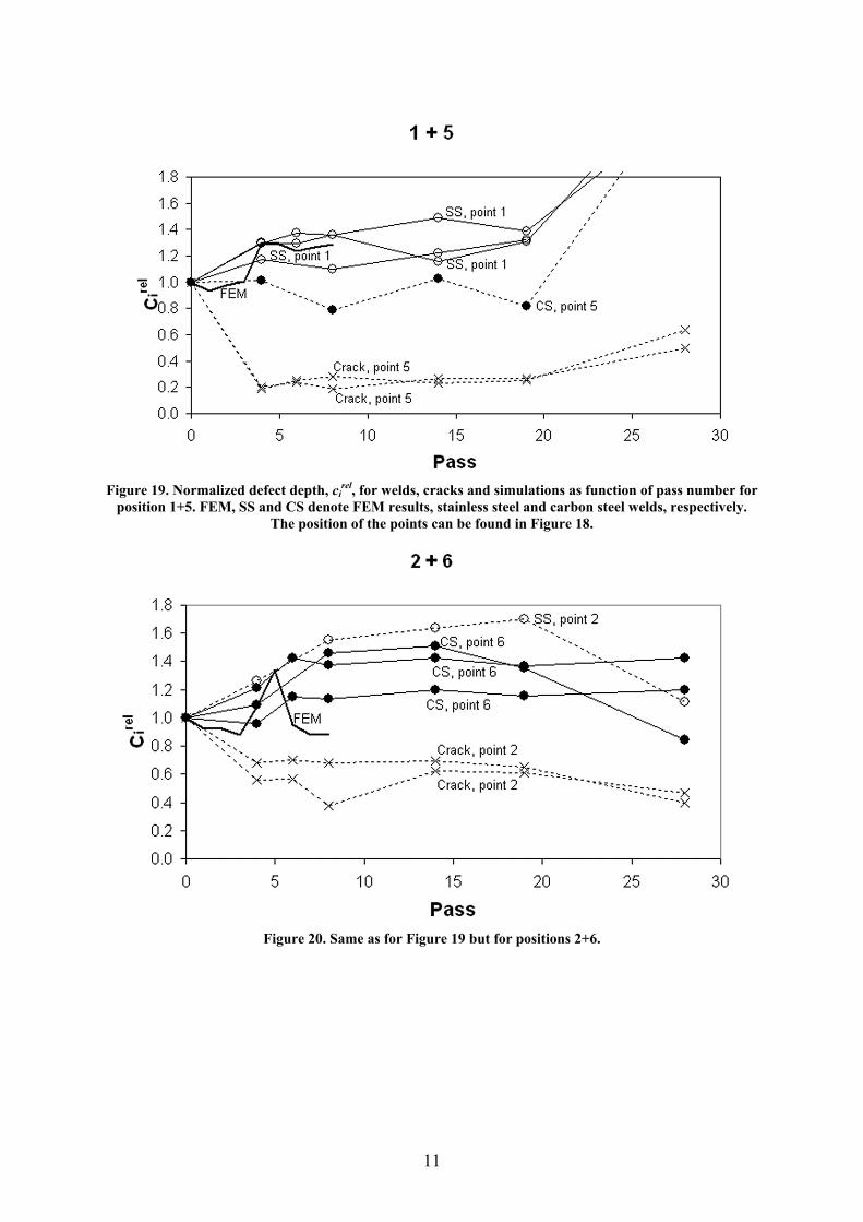
Figure 19. Normalized defect depth, cirel, for welds, cracks and simulations as function of pass number for
position 1+5. FEM, SS and CS denote FEM results, stainless steel and carbon steel welds, respectively. The position of the points can be found in Figure 18.
Figure 20. Same as for Figure 19 but for positions 2+6.
11

Figure 21. Same as for Figure 19 but for positions 3+7.
Figure 22. Same as for Figure 19 but for positions 4+8.
When comparing the samples from experiments with the mesh from the rotated workpiece, see Figure 23 - Figure 26, the mesh and the stainless steel wire have deformed similar. Since the workpiece in these FE simulations has been rotated before entering the pass and the agreement between calculations and experiments is good, the bar in the experiments must have rotated before pass 1 as well.
12

Figure 23. Combination of two X-ray pictures of the sample retouched to improve contrast and the mesh from the rotated FE-simulation for pass 1.
Figure 24. As in Figure 23, but for pass 2.
Figure 25. As in Figure 23, but for pass 3.
Figure 26. As in Figure 23, but for pass 4.
6 Conclusions
6.1 Surface deformation • ci
rel decreases for all longitudinal surface cracks in the first four passes, except for cracks in position 7, and remains low for all subsequent passes.
• Results from the FE simulations predict the reduction of the welds satisfactory except for positions 4 and 8, where the simulations show less reduction than the experiments.
• To better predict crack reduction, cracks must be modeled in the FE simulations rather than monitoring the location of a subsurface node in a solid bar.
6.2 Inner deformation • In the experiments of the inner deformation of the bar it was found that the workpiece
rotates 20° before pass 1 in the FE simulations, but after the upset the rotation is reduced to approximately 10° due to the deformation and this rotation remains throughout the subsequent rolling.
• The results from the FE simulation with an initially rotated workpiece show a very good agreement with the results from the experiments.
• The insertion of a metal grid in a bar as presented in the present work is a good method to determine the deformation of the cross-section of a bar.
13

7 References [1] Walzdrahtfehler, (1973), Verein Deutcher Eisenhuttenleute, Düsseldorf. [2] K. N. Barlow, P. R. Lancaster and R. T. Maddison (1984), "Examination of surface
defects induced during hot rolling of high-alloy steel bar and rod", Metals Technology, 11.
[3] MNC handbok nr 11, Verktygsstål, Snabbstål, (1983), SIS. [4] Tool steels, (1998), ASM International. [5] Steels heat treatment and processing principles, (1990), ASM International. [6] Marc manual 2005r2, (2004), MSC.Software Corporation. [7] W. Roberts (1985), "Calculation of flow curves pertinent to multi-step hot-working
operations", Internal report KIMAB, IM-2037, Drottning Kristinas v. 48, SE-114 28 Stockholm, Sweden.
[8] S. Riljak (2004), "Experimental and numerical analysis of hot rolling in wire block", The 7th Esaform Conference on Material Forming, Trondheim, Norway.
14