Supra MKIV Full Repair Manual
258
1. Introduction
-
Upload
discocyclina -
Category
Documents
-
view
2.892 -
download
6
Transcript of Supra MKIV Full Repair Manual

1. Introduction
2
DEVELOPMENT OBJECTIVES
As Toyota’s high–performance flagship car, the Toyota Supra continues to make full use of available advanced
technology.
In its fourth full model change, the Toyota Supra has been reborn, making great strides in becoming recognized as a
full–fledged, world class sports car.
The major development objectives of the new Toyota Supra are as follows:
�Styling
Timeless exterior design worthy of a muscular high–performance sports car
�Interior
Dynamic interior design with a sporty image
�Power Train
Boasting overwhelming power and response
�Chassis
Offering communicative steering feel and superb response through stable and precise handling
�Safety
High safety factors matching its high–speed driving capability
�Weight Reduction
Trimming extra weight to realize the vehicle’s full potential
�Environment
The new refrigerant R134a is used for the air conditioning system
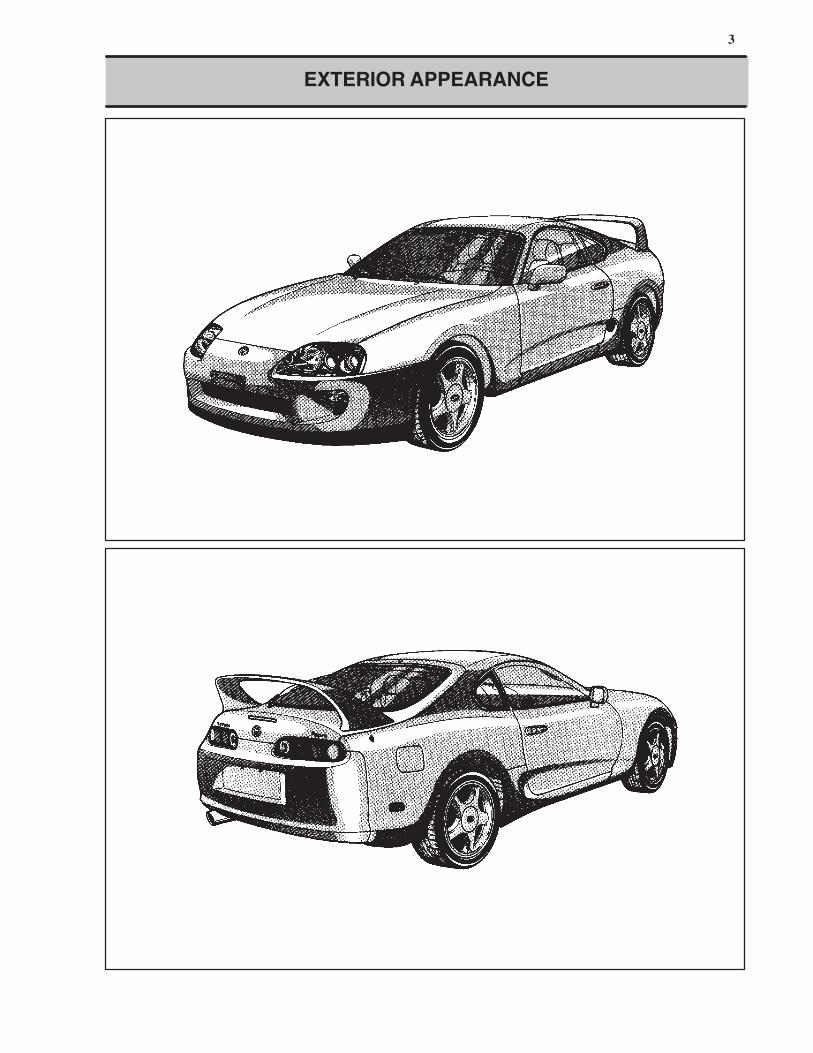
3
EXTERIOR APPEARANCE
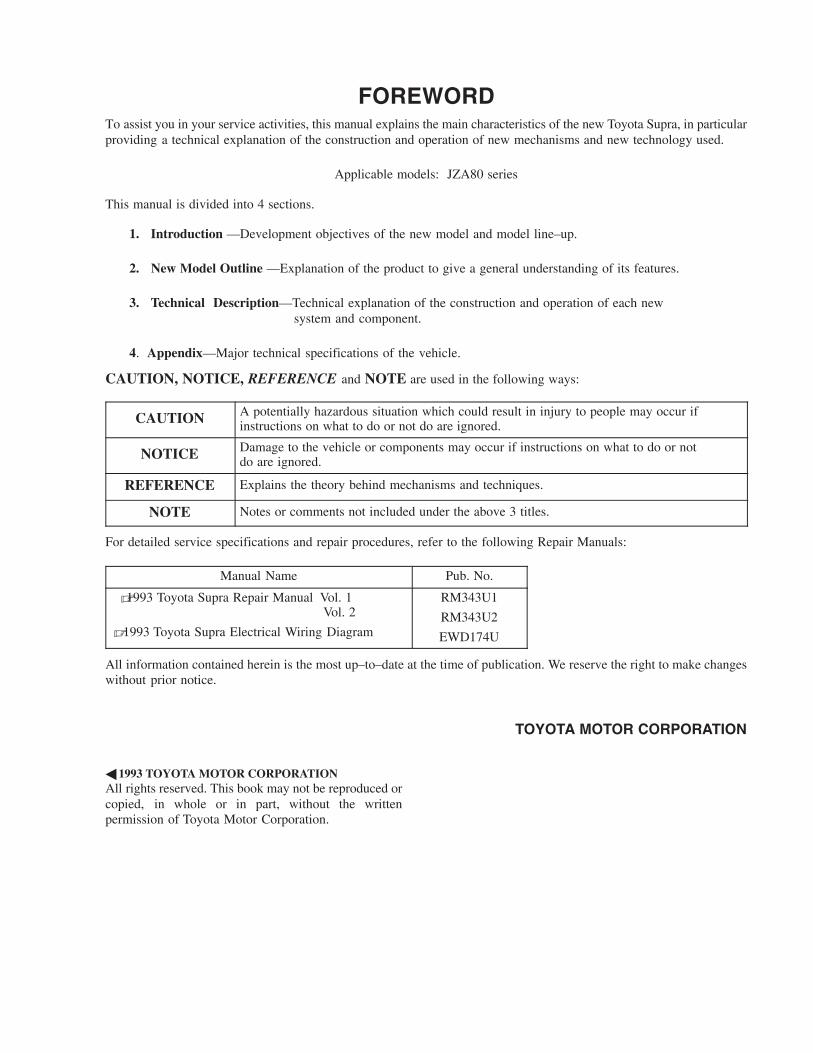
FOREWORDTo assist you in your service activities, this manual explains the main characteristics of the new Toyota Supra, in particular
providing a technical explanation of the construction and operation of new mechanisms and new technology used.
Applicable models: JZA80 series
This manual is divided into 4 sections.
1. Introduction —Development objectives of the new model and model line–up.
2. New Model Outline —Explanation of the product to give a general understanding of its features.
3. Technical Description—Technical explanation of the construction and operation of each new
system and component.
4. Appendix—Major technical specifications of the vehicle.
CAUTION, NOTICE, REFERENCE and NOTE are used in the following ways:
CAUTIONA potentially hazardous situation which could result in injury to people may occur ifinstructions on what to do or not do are ignored.
NOTICEDamage to the vehicle or components may occur if instructions on what to do or notdo are ignored.
REFERENCE Explains the theory behind mechanisms and techniques.
NOTE Notes or comments not included under the above 3 titles.
For detailed service specifications and repair procedures, refer to the following Repair Manuals:
Manual Name Pub. No.
�1993 Toyota Supra Repair Manual Vol. 1 Vol. 2
� 1993 Toyota Supra Electrical Wiring Diagram
RM343U1
RM343U2
EWD174U
All information contained herein is the most up–to–date at the time of publication. We reserve the right to make changes
without prior notice.
TOYOTA MOTOR CORPORATION
� 1993 TOYOTA MOTOR CORPORATION
All rights reserved. This book may not be reproduced or
copied, in whole or in part, without the written
permission of Toyota Motor Corporation.
4
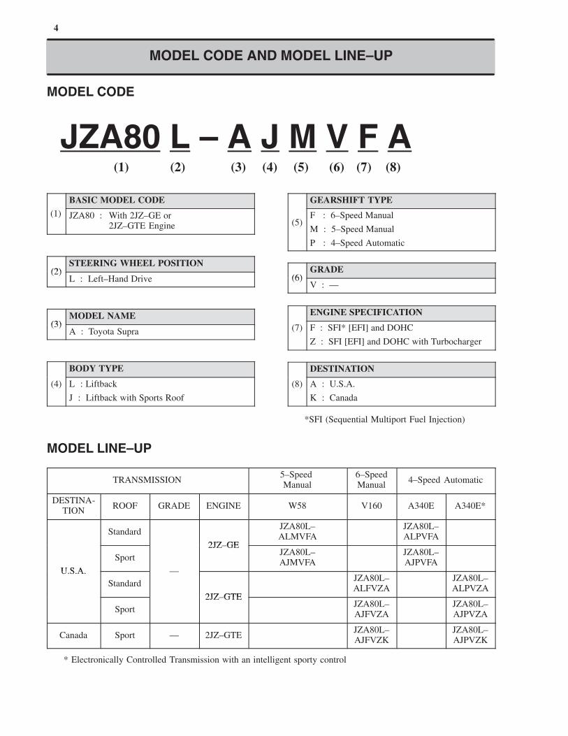
MODEL CODE AND MODEL LINE–UP
MODEL CODE
JZA80 L – A J M V F A(1) (2) (3) (4) (5) (6) (7) (8)
BASIC MODEL CODE
(1) JZA80 : With 2JZ–GE or2JZ–GTE Engine
(2)STEERING WHEEL POSITION
(2)L : Left–Hand Drive
(3)MODEL NAME
(3)A : Toyota Supra
BODY TYPE
(4) L : Liftback
J : Liftback with Sports Roof
GEARSHIFT TYPE
(5)F : 6–Speed Manual
M : 5–Speed Manual
P : 4–Speed Automatic
(6)GRADE
(6)V : —
ENGINE SPECIFICATION
(7) F : SFI* [EFI] and DOHC
Z : SFI [EFI] and DOHC with Turbocharger
DESTINATION
(8) A : U.S.A.
K : Canada
*SFI (Sequential Multiport Fuel Injection)
MODEL LINE–UP
TRANSMISSION5–Speed Manual
6–SpeedManual
4–Speed Automatic
DESTINA-TION
ROOF GRADE ENGINE W58 V160 A340E A340E*
Standard
2JZ GE
JZA80L–ALMVFA
JZA80L–ALPVFA
U S A
Sport
2JZ–GEJZA80L–AJMVFA
JZA80L–AJPVFA
U.S.A.
Standard
—
2JZ GTE
JZA80L–ALFVZA
JZA80L–ALPVZA
Sport
2JZ–GTEJZA80L–AJFVZA
JZA80L–AJPVZA
Canada Sport — 2JZ–GTEJZA80L–AJFVZK
JZA80L–AJPVZK
* Electronically Controlled Transmission with an intelligent sporty control

2. New Model Outline

6
MAJOR COMPONENTS
The basic components of the new Toyota Supra are as follows.
ModelNew Previous
ItemNew Previous
Drive SystemFR (Front Engine,Rear Wheel Drive)
←
Type 2JZ–GE: In–line 6, 3.0–Liter 7M–GE: In–Line 6, 3.0–Liter
Displacement cm3 (cu. in.) 2997 (182.9) 2954 (180.3)
Valve Mechanism 24 Valve, DOHC ←
Fuel System SFI*1 [EFI] MFI*2 [EFI]
Max. Output [SAE–NET]kW @ rpm (HP @ rpm)
164 @ 5800 (220 @ 5800) 149 @ 6000 (200 @ 6000)
Max. Torque [SAE–NET]N.m @ rpm(ft.lbf @ rpm)
285 @ 4800 (210 @ 4800) 255 @ 3600 (188 @ 3600)
Type 2JZ–GTE: In–line 6, 3.0–Liter 7M–GTE: In–Line 6, 3.0–Liter
Displacement cm3 (cu. in.) 2997 (182.9) 2954 (180.3)
Valve Mechanism 24 Valves, DOHC ←
Fuel System SFI*1 [EFI] MFI*2 [EFI]
Max. Output [SAE–NET]kW @ rpm (HP @ rpm)
239 @ 5600 (320 @ 5600) 173 @ 5600 (232 @ 5600)
Max. Torque [SAE–NET]N.m @ rpm (ft.lbf @ rpm)
427 @ 4000 (315 @ 4000) 344 @ 3200 (254 @ 3200)
Clutch Dry Type, Single Plate ←
Trans-Manual
W58: 5–Speed (For 2JZ–GE)V160: 6–Speed (For 2JZ–GTE)
W58: 5–Speed (For 7M–GE)R154: 5–Speed (For 7M–GTE)Trans
missionAutomatic
A340E: 4–Speed (For 2JZ–GE)A340E*3: 4–Speed (For 2JZ–GTE)
A340E: 4–Speed (For 7M–GE)A340E: 4–Speed (For 7M–GTE)
Brakes 4–Wheel Ventilated Disc ←
Suspension 4–Wheel Double Wishbone ←
Gear Type Rack and Pinion ←
SteeringPower Steering
Vehicle Speed Sensing HydraulicReaction Type Electronically
Controlled PPS*4←
*1 SFI: Sequential Multiport Fuel Injection
*2 MFI: Multiport Fuel Injection
*3 Electronically Controlled Transmission with an intelligent sporty control
*4 PPS: Progressive Power Steering
DO
HC
wit
h T
urb
och
arger
DO
HC
Engin
e
7
Never make a mistake with the terminal connection position as this will cause a malfunction.
NOTICE
SERVICEABILITY IMPROVEMENT
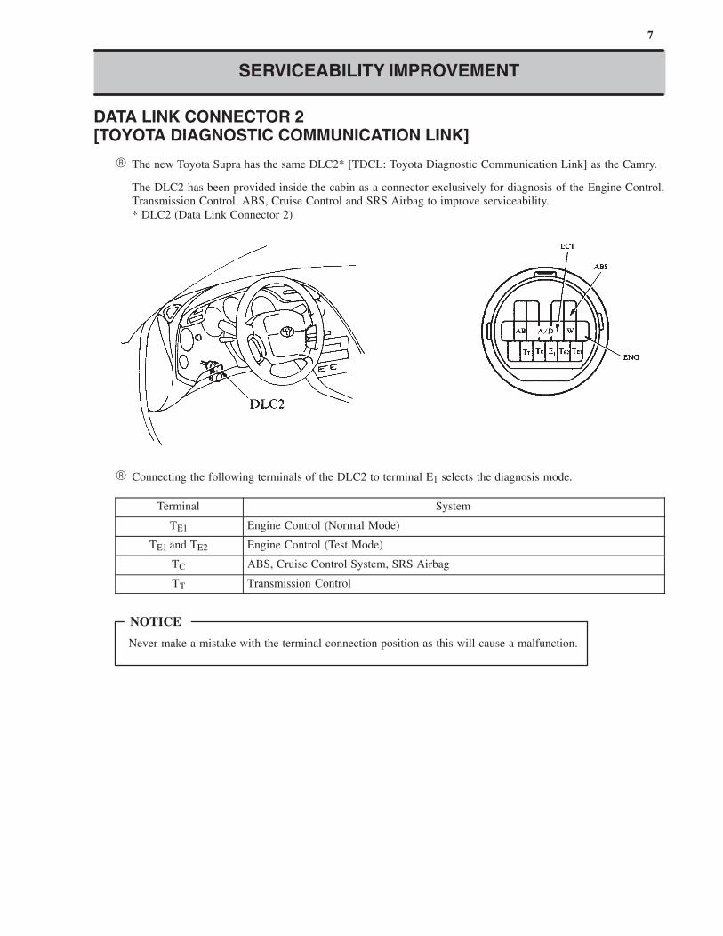
DATA LINK CONNECTOR 2[TOYOTA DIAGNOSTIC COMMUNICATION LINK]
� The new Toyota Supra has the same DLC2* [TDCL: Toyota Diagnostic Communication Link] as the Camry.
The DLC2 has been provided inside the cabin as a connector exclusively for diagnosis of the Engine Control,
Transmission Control, ABS, Cruise Control and SRS Airbag to improve serviceability.
* DLC2 (Data Link Connector 2)
� Connecting the following terminals of the DLC2 to terminal E1 selects the diagnosis mode.
Terminal System
TE1 Engine Control (Normal Mode)
TE1 and TE2 Engine Control (Test Mode)
TC ABS, Cruise Control System, SRS Airbag
TT Transmission Control
8
ENGINE
ENGINE LINE–UP
The following are the two newly developed engines that are available for the new Toyota Supra:
Displace-ment
Engine
Type
Max. Output
[SAE–NET]
Max. Torque
[SAE–NET]Features
3.0 L 2JZ–GE164 kW @ 5800 rpm(220 HP @ 5800 rpm)
285 N⋅m @ 4800 rpm(210 ft⋅lbf @ 4800 rpm)
An in–line 6, 3.0–liter DOHC engine,adopting ACIS* and dual exhaust man-ifold, offering high–performance andlow fuel consumption at high level.
3.0 L 2JZ–GTE239 kW @ 5600 rpm(320 HP @ 5600 rpm)
427 N⋅m @ 4000 rpm(315 ft⋅lbf @ 4000 rpm)
A turbocharged in–line 6, 3.0–literDOHC engine with a charge air cooler[intercooler], featuring high responseand power output.
*ACIS: An Acoustic Control Induction System, equivalent to the Intake Air Control System used in the 7M–GE engine
of the previous model.
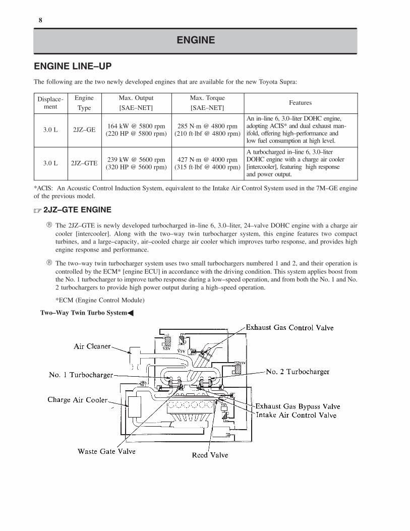
� 2JZ–GTE ENGINE
� The 2JZ–GTE is newly developed turbocharged in–line 6, 3.0–liter, 24–valve DOHC engine with a charge air
cooler [intercooler]. Along with the two–way twin turbocharger system, this engine features two compact
turbines, and a large–capacity, air–cooled charge air cooler which improves turbo response, and provides high
engine response and performance.
� The two–way twin turbocharger system uses two small turbochargers numbered 1 and 2, and their operation is
controlled by the ECM* [engine ECU] in accordance with the driving condition. This system applies boost from
the No. 1 turbocharger to improve turbo response during a low–speed operation, and from both the No. 1 and No.
2 turbochargers to provide high power output during a high–speed operation.
*ECM (Engine Control Module)
�Two–Way Twin Turbo System�
9
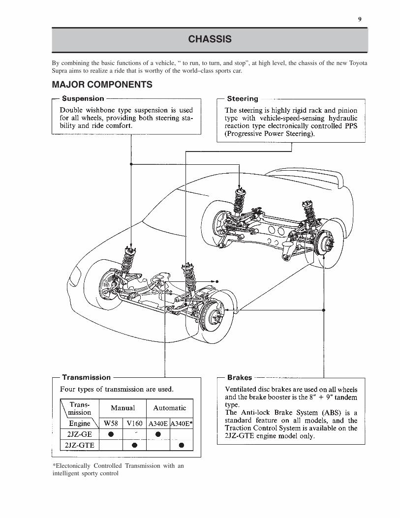
CHASSIS
By combining the basic functions of a vehicle, “ to run, to turn, and stop”, at high level, the chassis of the new Toyota
Supra aims to realize a ride that is worthy of the world–class sports car.
MAJOR COMPONENTS
*Electonically Controlled Transmission with an
intelligent sporty control
10
CHASSIS
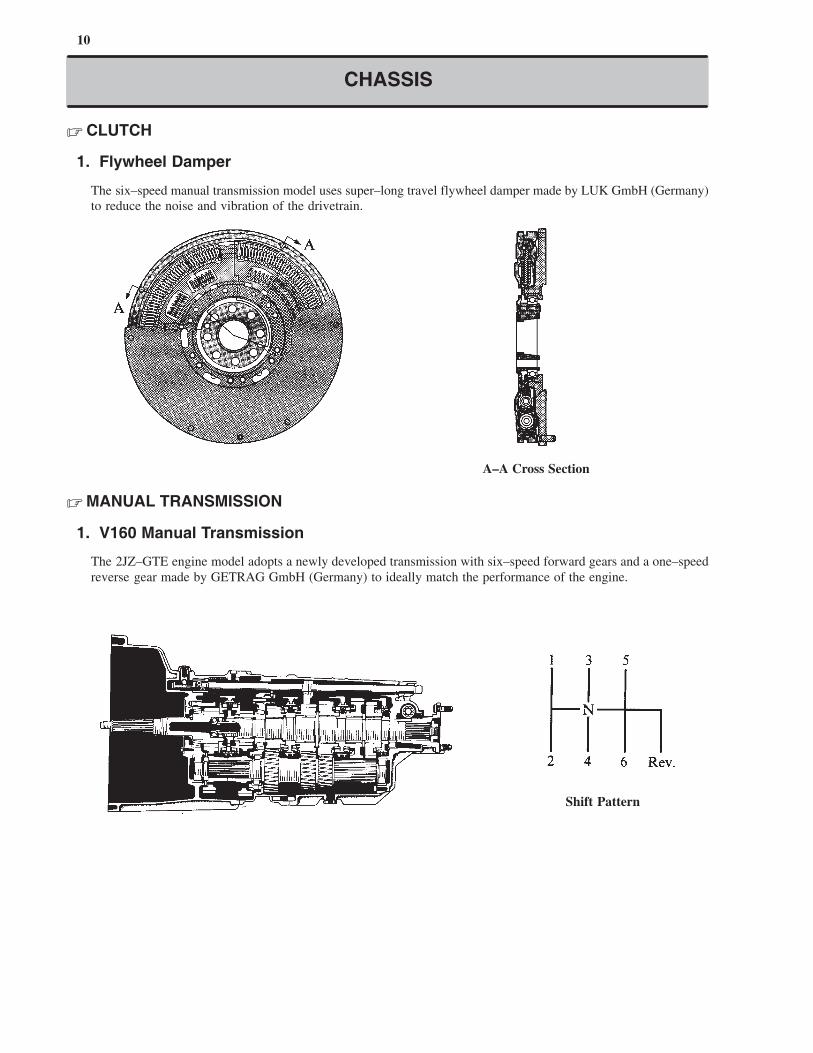
� CLUTCH
1. Flywheel Damper
The six–speed manual transmission model uses super–long travel flywheel damper made by LUK GmbH (Germany)
to reduce the noise and vibration of the drivetrain.
A–A Cross Section
� MANUAL TRANSMISSION
1. V160 Manual Transmission
The 2JZ–GTE engine model adopts a newly developed transmission with six–speed forward gears and a one–speed
reverse gear made by GETRAG GmbH (Germany) to ideally match the performance of the engine.
Shift Pattern
11
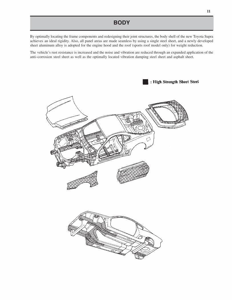
BODY
By optimally locating the frame components and redesigning their joint structures, the body shell of the new Toyota Supra
achieves an ideal rigidity. Also, all panel areas are made seamless by using a single steel sheet, and a newly developed
sheet aluminum alloy is adopted for the engine hood and the roof (sports roof model only) for weight reduction.
The vehicle’s rust resistance is increased and the noise and vibration are reduced through an expanded application of the
anti–corrosion steel sheet as well as the optimally located vibration damping steel sheet and asphalt sheet.
12
EXTERIOR
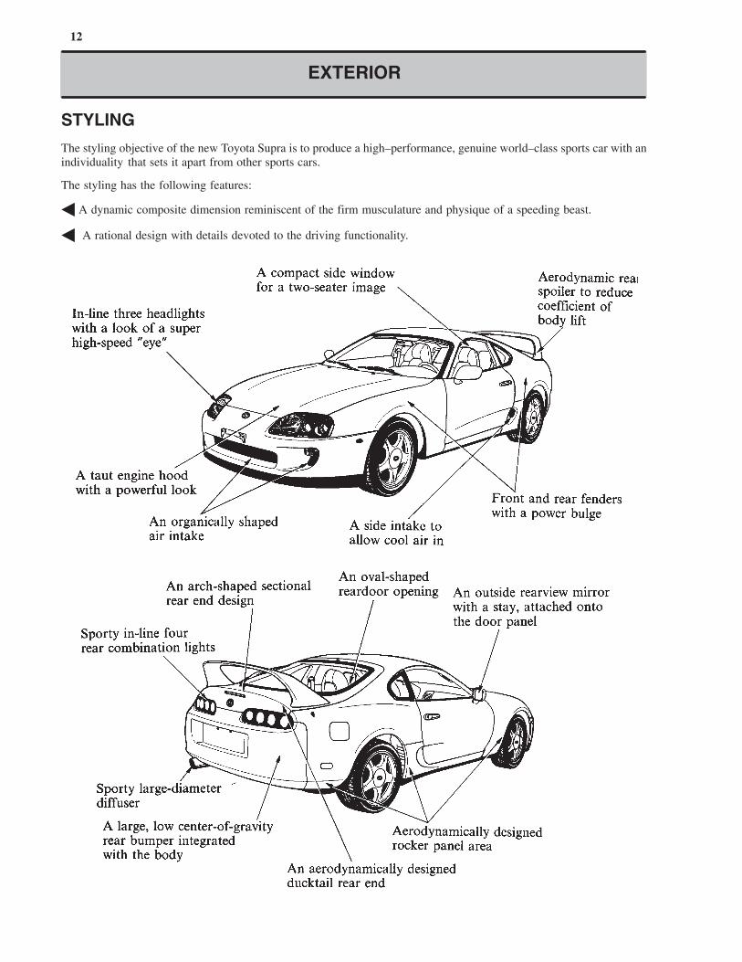
STYLING
The styling objective of the new Toyota Supra is to produce a high–performance, genuine world–class sports car with an
individuality that sets it apart from other sports cars.
The styling has the following features:
� A dynamic composite dimension reminiscent of the firm musculature and physique of a speeding beast.
� A rational design with details devoted to the driving functionality.
13
EXTERIOR
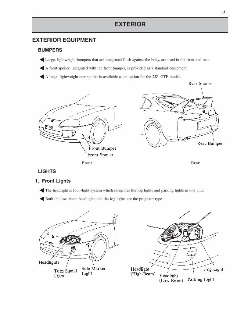
EXTERIOR EQUIPMENT
� BUMPERS
� Large, lightweight bumpers that are integrated flush against the body, are used in the front and rear.
� A front spoiler, integrated with the front bumper, is provided as a standard equipment.
� A large, lightweight rear spoiler is available as an option for the 2JZ–GTE model.
Front Rear
� LIGHTS
1. Front Lights
� The headlight is four–light system which integrates the fog lights and parking lights in one unit.
� Both the low–beam headlights and the fog lights are the projector type.
14
EXTERIOR
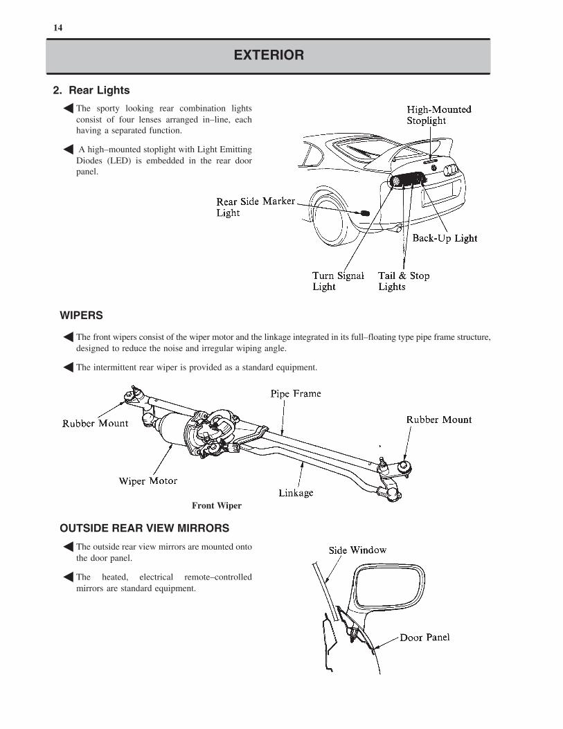
2. Rear Lights
� The sporty looking rear combination lights
consist of four lenses arranged in–line, each
having a separated function.
� A high–mounted stoplight with Light Emitting
Diodes (LED) is embedded in the rear door
panel.
� WIPERS
� The front wipers consist of the wiper motor and the linkage integrated in its full–floating type pipe frame structure,
designed to reduce the noise and irregular wiping angle.
� The intermittent rear wiper is provided as a standard equipment.
Front Wiper
� OUTSIDE REAR VIEW MIRRORS
� The outside rear view mirrors are mounted onto
the door panel.
� The heated, electrical remote–controlled
mirrors are standard equipment.
15
Your Supra has been fitted with specially developed tires which provide exceptional dynamic
performance under general road conditions. However, (on vehicles equipped with the 2JZ–GTE
engine,) you may also notice that your tires wear more rapidly than standard tires as a result of
their superior performance.
NOTICE
EXTERIOR
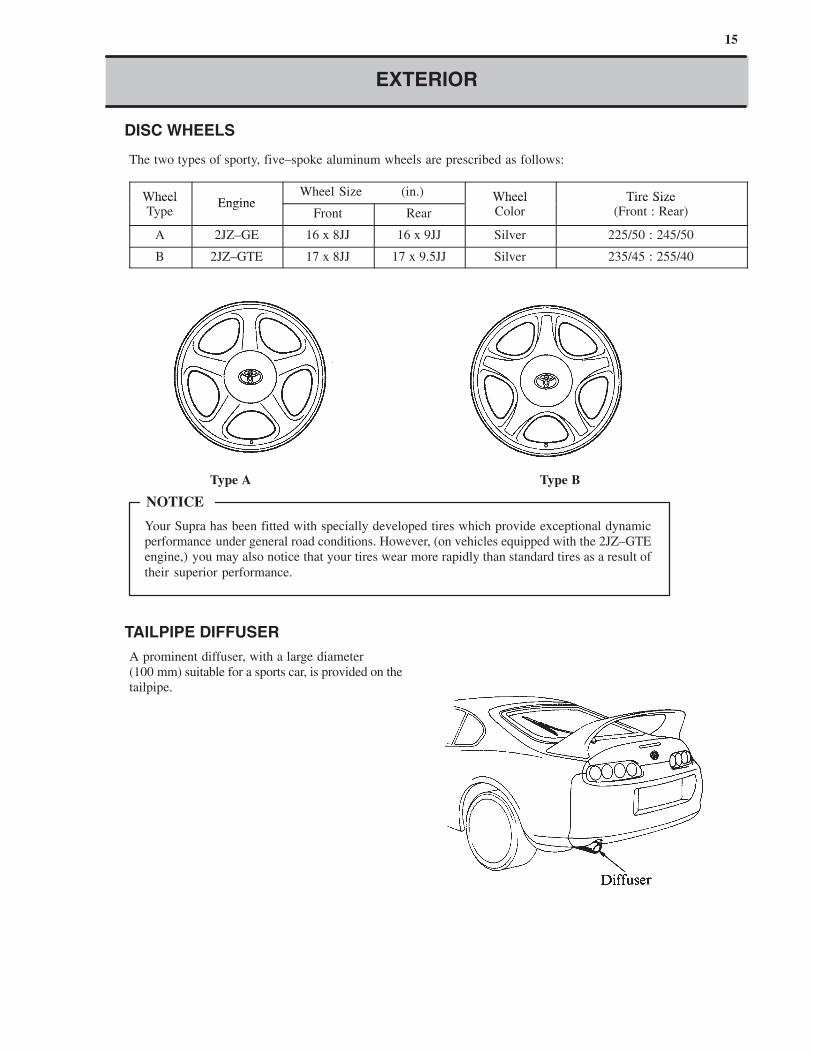
� DISC WHEELS
The two types of sporty, five–spoke aluminum wheels are prescribed as follows:
WheelEngine
Wheel Size (in.) Wheel Tire SizeWheelType
EngineFront Rear
WheelColor
Tire Size(Front : Rear)
A 2JZ–GE 16 x 8JJ 16 x 9JJ Silver 225/50 : 245/50
B 2JZ–GTE 17 x 8JJ 17 x 9.5JJ Silver 235/45 : 255/40
Type A Type B
� TAILPIPE DIFFUSER
A prominent diffuser, with a large diameter
(100 mm) suitable for a sports car, is provided on the
tailpipe.
16
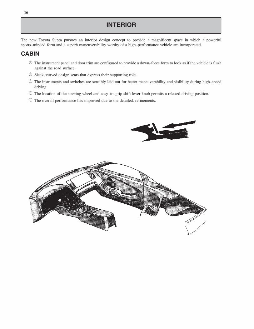
INTERIOR
The new Toyota Supra pursues an interior design concept to provide a magnificent space in which a powerful
sports–minded form and a superb maneuverability worthy of a high–performance vehicle are incorporated.
CABIN
� The instrument panel and door trim are configured to provide a down–force form to look as if the vehicle is flush
against the road surface.
� Sleek, curved design seats that express their supporting role.
� The instruments and switches are sensibly laid out for better maneuverability and visibility during high–speed
driving.
� The location of the steering wheel and easy–to–grip shift lever knob permits a relaxed driving position.
� The overall performance has improved due to the detailed. refinements.
17
�: Manual
�: Power
INTERIOR
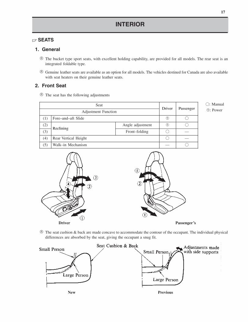
� SEATS
1. General
� The bucket type sport seats, with excellent holding capability, are provided for all models. The rear seat is an
integrated foldable type.
� Genuine leather seats are available as an option for all models. The vehicles destined for Canada are also available
with seat heaters on their genuine leather seats.
2. Front Seat
� The seat has the following adjustments
SeatDriver Passenger
Adjustment FunctionDriver Passenger
(1) Fore–and–aft Slide � �
(2)Reclining
Angle adjustment � �
(3)Reclining
Front–folding � —
(4) Rear Vertical Height � —
(5) Walk–in Mechanism — �
Driver Passenger’s
� The seat cushion & back are made concave to accommodate the contour of the occupant. The individual physical
differences are absorbed by the seat, giving the occupant a snug fit.
New Previous
18
INTERIOR
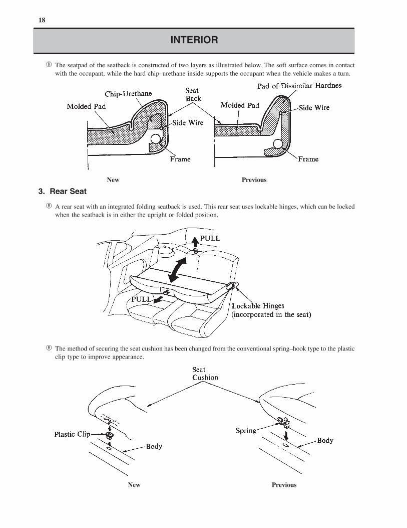
� The seatpad of the seatback is constructed of two layers as illustrated below. The soft surface comes in contact
with the occupant, while the hard chip–urethane inside supports the occupant when the vehicle makes a turn.
New Previous
3. Rear Seat
� A rear seat with an integrated folding seatback is used. This rear seat uses lockable hinges, which can be locked
when the seatback is in either the upright or folded position.
� The method of securing the seat cushion has been changed from the conventional spring–hook type to the plastic
clip type to improve appearance.
New Previous
19
INTERIOR
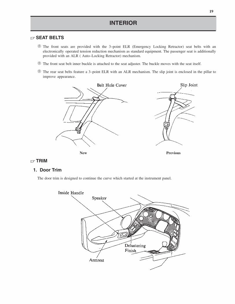
� SEAT BELTS
� The front seats are provided with the 3–point ELR (Emergency Locking Retractor) seat belts with an
electronically operated tension reduction mechanism as standard equipment. The passenger seat is additionally
provided with an ALR ( Auto–Locking Retractor) mechanism.
� The front seat belt inner buckle is attached to the seat adjuster. The buckle moves with the seat itself.
� The rear seat belts feature a 3–point ELR with an ALR mechanism. The slip joint is enclosed in the pillar to
improve appearance.
New Previous
� TRIM
1. Door Trim
The door trim is designed to continue the curve which started at the instrument panel.
20
INTERIOR
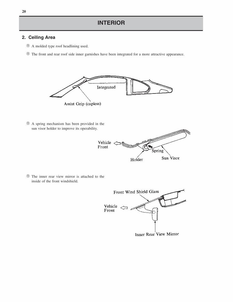
2. Ceiling Area
� A molded type roof headlining used.
� The front and rear roof side inner garnishes have been integrated for a more attractive appearance.
� A spring mechanism has been provided in the
sun visor holder to improve its operability.
� The inner rear view mirror is attached to the
inside of the front windshield.
21
INTERIOR
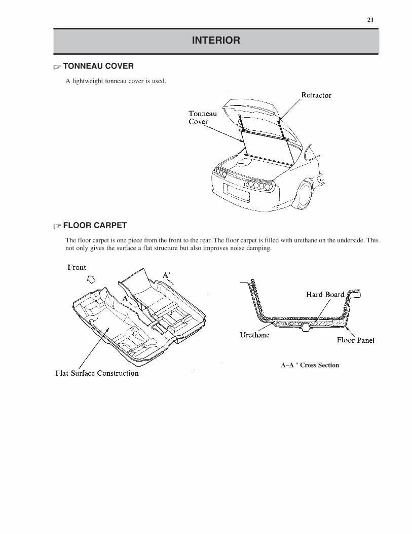
� TONNEAU COVER
A lightweight tonneau cover is used.
� FLOOR CARPET
The floor carpet is one piece from the front to the rear. The floor carpet is filled with urethane on the underside. This
not only gives the surface a flat structure but also improves noise damping.
A–A ’ Cross Section
22
INTERIOR
INSTRUMENT PANEL, SWITCH LAYOUT AND EQUIPMENT
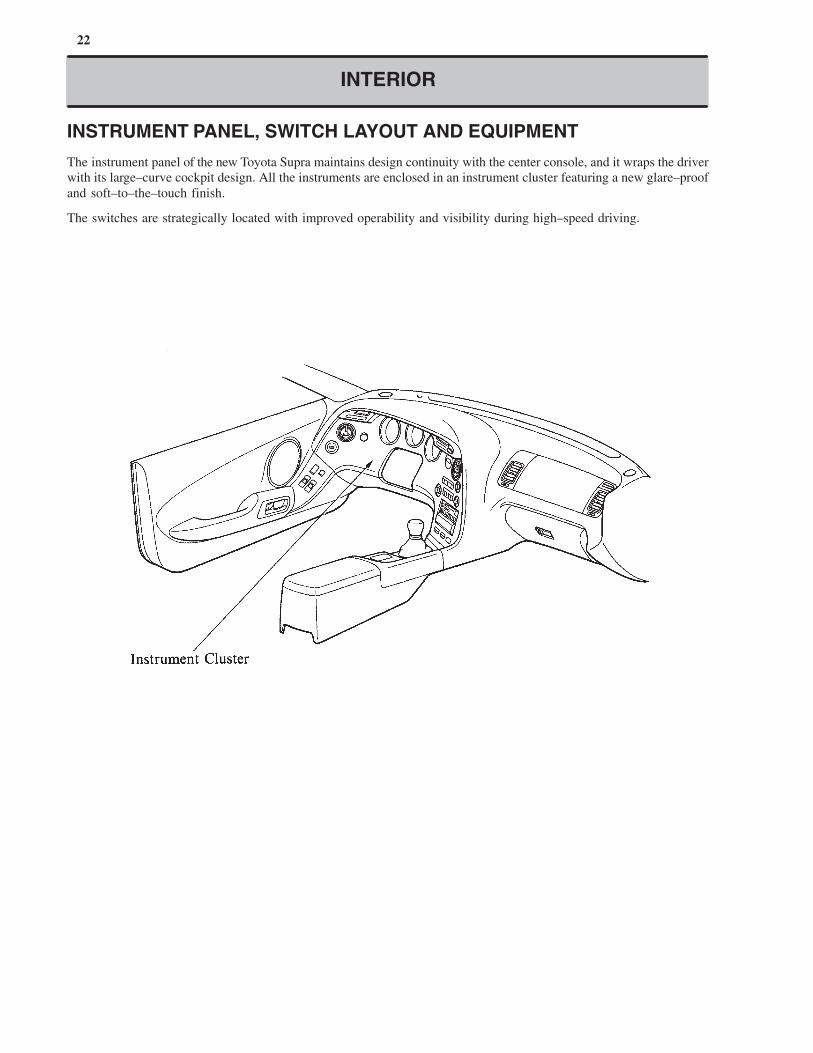
The instrument panel of the new Toyota Supra maintains design continuity with the center console, and it wraps the driver
with its large–curve cockpit design. All the instruments are enclosed in an instrument cluster featuring a new glare–proof
and soft–to–the–touch finish.
The switches are strategically located with improved operability and visibility during high–speed driving.
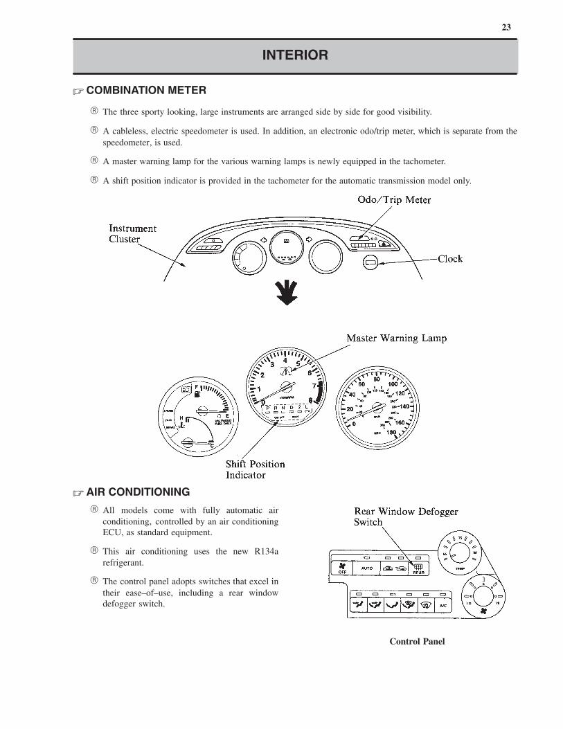
23
Control Panel
INTERIOR
� COMBINATION METER
� The three sporty looking, large instruments are arranged side by side for good visibility.
� A cableless, electric speedometer is used. In addition, an electronic odo/trip meter, which is separate from the
speedometer, is used.
� A master warning lamp for the various warning lamps is newly equipped in the tachometer.
� A shift position indicator is provided in the tachometer for the automatic transmission model only.
� AIR CONDITIONING
� All models come with fully automatic air
conditioning, controlled by an air conditioning
ECU, as standard equipment.
� This air conditioning uses the new R134a
refrigerant.
� The control panel adopts switches that excel in
their ease–of–use, including a rear window
defogger switch.
24
INTERIOR
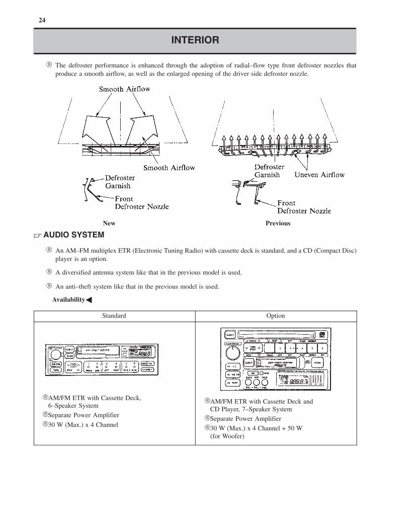
� The defroster performance is enhanced through the adoption of radial–flow type front defroster nozzles that
produce a smooth airflow, as well as the enlarged opening of the driver side defroster nozzle.
New Previous
� AUDIO SYSTEM
� An AM–FM multiplex ETR (Electronic Tuning Radio) with cassette deck is standard, and a CD (Compact Disc)
player is an option.
� A diversified antenna system like that in the previous model is used.
� An anti–theft system like that in the previous model is used.
�Availability�
Standard Option
�AM/FM ETR with Cassette Deck,
6–Speaker System
�Separate Power Amplifier
�30 W (Max.) x 4 Channel
�AM/FM ETR with Cassette Deck and
CD Player, 7–Speaker System
�Separate Power Amplifier
�30 W (Max.) x 4 Channel + 50 W
(for Woofer)
25
INTERIOR
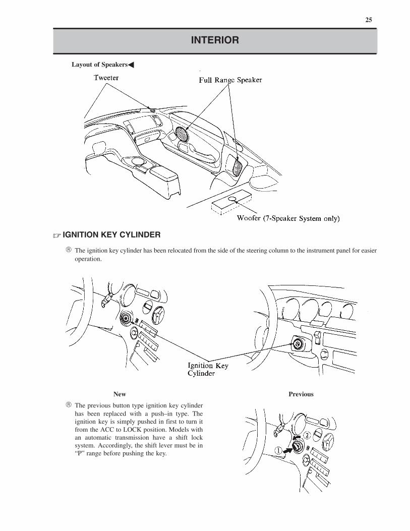
�Layout of Speakers�
� IGNITION KEY CYLINDER
� The ignition key cylinder has been relocated from the side of the steering column to the instrument panel for easier
operation.
New Previous
� The previous button type ignition key cylinder
has been replaced with a push–in type. The
ignition key is simply pushed in first to turn it
from the ACC to LOCK position. Models with
an automatic transmission have a shift lock
system. Accordingly, the shift lever must be in
“P” range before pushing the key.
26
SAFETY AND ENVIRONMENT
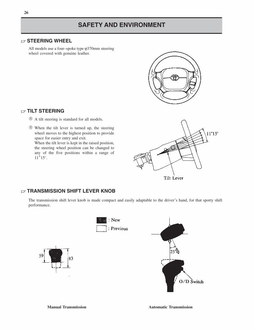
� STEERING WHEEL
All models use a four–spoke type ϕ370mm steering
wheel covered with genuine leather.
� TILT STEERING
� A tilt steering is standard for all models.
� When the tilt lever is turned up, the steering
wheel moves to the highest position to provide
space for easier entry and exit.
When the tilt lever is kept in the raised position,
the steering wheel position can be changed to
any of the five positions within a range of
11°15’.
� TRANSMISSION SHIFT LEVER KNOB
The transmission shift lever knob is made compact and easily adaptable to the driver’s hand, for that sporty shift
performance.
Manual Transmission Automatic Transmission
27
INTERIOR
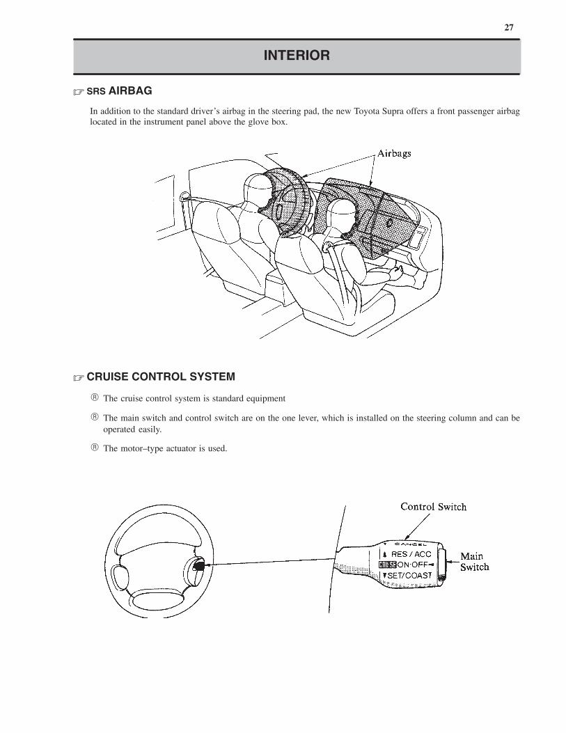
� SRS AIRBAG
In addition to the standard driver’s airbag in the steering pad, the new Toyota Supra offers a front passenger airbag
located in the instrument panel above the glove box.
� CRUISE CONTROL SYSTEM
� The cruise control system is standard equipment
� The main switch and control switch are on the one lever, which is installed on the steering column and can be
operated easily.
� The motor–type actuator is used.
28
Driver Side
INTERIOR
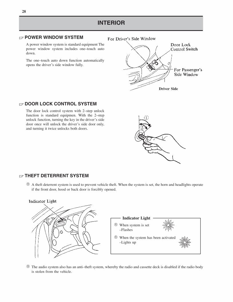
� POWER WINDOW SYSTEM
A power window system is standard equipment The
power window system includes one–touch auto
down.
The one–touch auto down function automatically
opens the driver’s side window fully.
� DOOR LOCK CONTROL SYSTEM
The door lock control system with 2–step unlock
function is standard equipmen. With the 2–step
unlock function, turning the key in the driver’s side
door once will unlock the driver’s side door only,
and turning it twice unlocks both doors.
� THEFT DETERRENT SYSTEM
� A theft deterrent system is used to prevent vehicle theft. When the system is set, the horn and headlights operate
if the front door, hood or back door is forcibly opened.
� When system is set
–Flashes
� When the system has been activated
–Lights up
Indicator Light
� The audio system also has an anti–theft system, whereby the radio and cassette deck is disabled if the radio body
is stolen from the vehicle.
29
INTERIOR
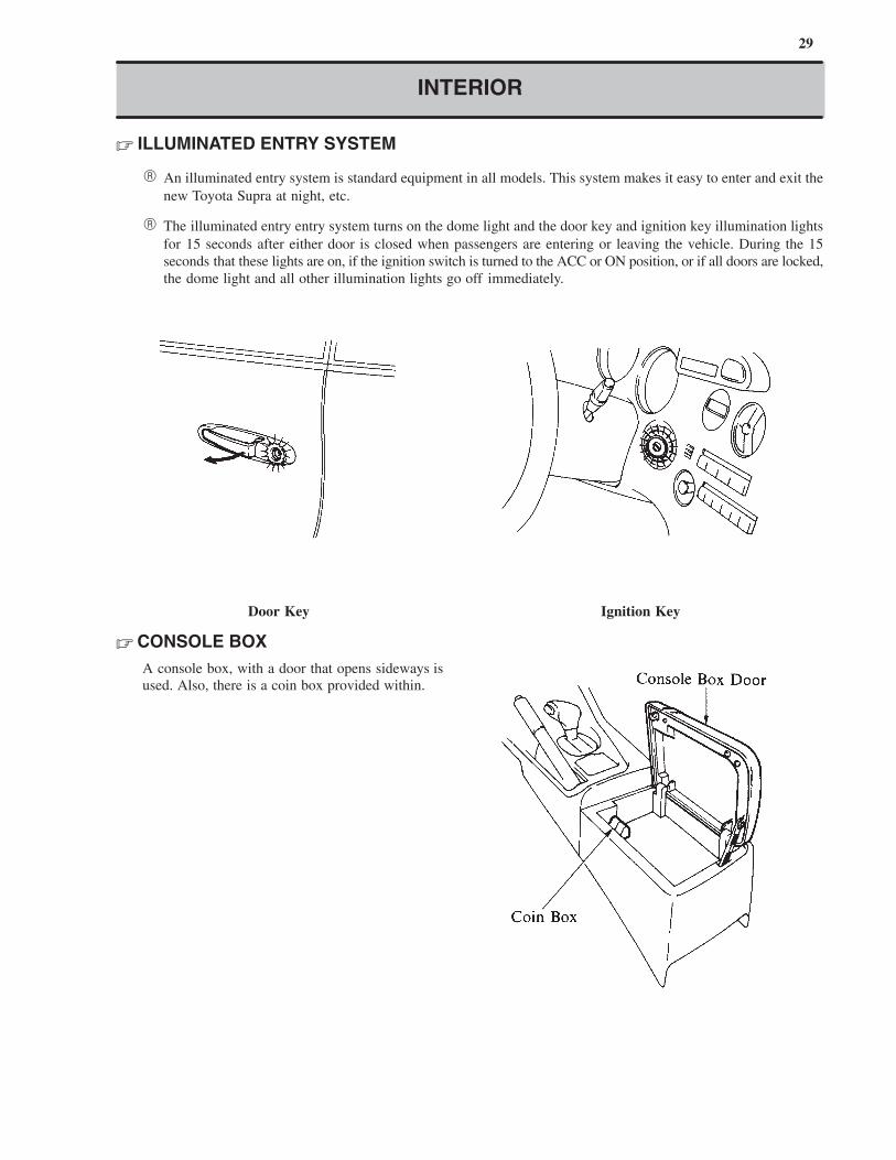
� ILLUMINATED ENTRY SYSTEM
� An illuminated entry system is standard equipment in all models. This system makes it easy to enter and exit the
new Toyota Supra at night, etc.
� The illuminated entry entry system turns on the dome light and the door key and ignition key illumination lights
for 15 seconds after either door is closed when passengers are entering or leaving the vehicle. During the 15
seconds that these lights are on, if the ignition switch is turned to the ACC or ON position, or if all doors are locked,
the dome light and all other illumination lights go off immediately.
Door Key Ignition Key
� CONSOLE BOX
A console box, with a door that opens sideways is
used. Also, there is a coin box provided within.
30
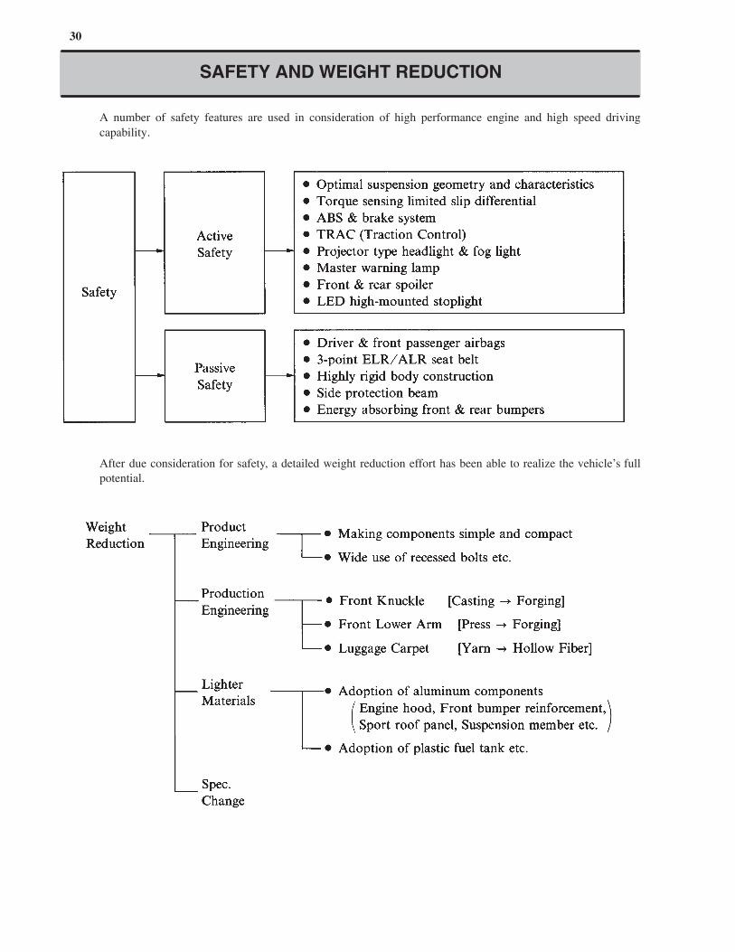
SAFETY AND WEIGHT REDUCTION
� A number of safety features are used in consideration of high performance engine and high speed driving
capability.
� After due consideration for safety, a detailed weight reduction effort has been able to realize the vehicle’s full
potential.

3. Technical Description

32 ENGINE — 2JZ–GE ENGINE
ENGINE
2JZ–GE ENGINE
� DESCRIPTION
The 2JZ–GE engine, which is newly–developed in place of the previous 7M–GE engine, is an in–line 6, 3.0 liter,
24–valve DOHC engine designed to run best at medium to high speeds. With such features as a higher compression
ratio, ACIS* (Acoustic Control Induction System) and dual exhaust manifolds, all contributing to a higher intake and
exhaust efficiency, this engine provides both high power output and high fuel efficiency at high levels. Additionally,
in California specification models, an Air Assist System and stainless steel exhaust manifolds are used to reduce HC
emissions.
*: The ACIS is identical to the Intake Air Control System in the 7M–GE engine.
�Except California Specification Models�
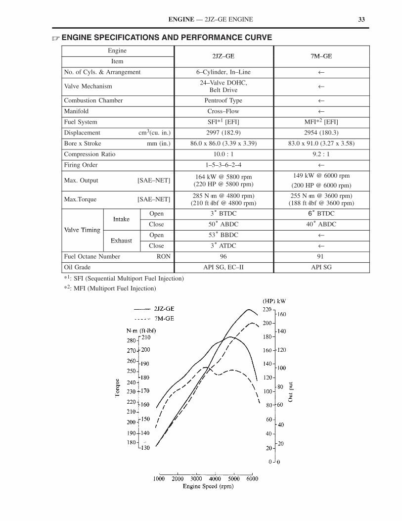
33ENGINE — 2JZ–GE ENGINE
� ENGINE SPECIFICATIONS AND PERFORMANCE CURVE
Engine2JZ GE 7M GE
Item2JZ–GE 7M–GE
No. of Cyls. & Arrangement 6–Cylinder, In–Line ←
Valve Mechanism24–Valve DOHC,
Belt Drive←
Combustion Chamber Pentroof Type ←
Manifold Cross–Flow ←
Fuel System SFI*1 [EFI] MFI*2 [EFI]
Displacement cm3(cu. in.) 2997 (182.9) 2954 (180.3)
Bore x Stroke mm (in.) 86.0 x 86.0 (3.39 x 3.39) 83.0 x 91.0 (3.27 x 3.58)
Compression Ratio 10.0 : 1 9.2 : 1
Firing Order 1–5–3–6–2–4 ←
Max. Output [SAE–NET]164 kW @ 5800 rpm(220 HP @ 5800 rpm)
149 kW @ 6000 rpm
(200 HP @ 6000 rpm)
Max.Torque [SAE–NET]285 N �m @ 4800 rpm)
(210 ft �lbf @ 4800 rpm)255 N �m @ 3600 rpm)
(188 ft �lbf @ 3600 rpm)
IntakeOpen 3° BTDC 6° BTDC
Valve Timing
IntakeClose 50° ABDC 40° ABDC
Valve Timing
ExhaustOpen 53° BBDC ←
ExhaustClose 3° ATDC ←
Fuel Octane Number RON 96 91
Oil Grade API SG, EC–II API SG
*1: SFI (Sequential Multiport Fuel Injection)
*2: MFI (Multiport Fuel Injection)
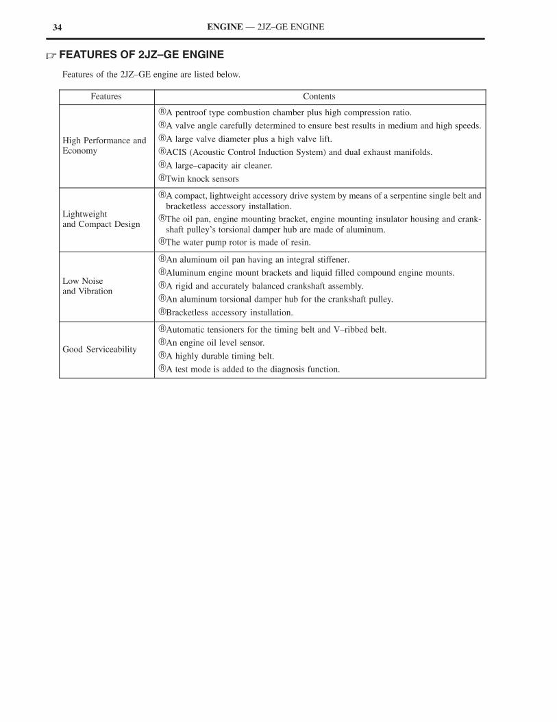
34 ENGINE — 2JZ–GE ENGINE
� FEATURES OF 2JZ–GE ENGINE
Features of the 2JZ–GE engine are listed below.
Features Contents
High Performance andEconomy
�A pentroof type combustion chamber plus high compression ratio.
�A valve angle carefully determined to ensure best results in medium and high speeds.
�A large valve diameter plus a high valve lift.
�ACIS (Acoustic Control Induction System) and dual exhaust manifolds.
�A large–capacity air cleaner.
�Twin knock sensors
Lightweightand Compact Design
�A compact, lightweight accessory drive system by means of a serpentine single belt and
bracketless accessory installation.
�The oil pan, engine mounting bracket, engine mounting insulator housing and crank-
shaft pulley’s torsional damper hub are made of aluminum.
�The water pump rotor is made of resin.
Low Noise and Vibration
�An aluminum oil pan having an integral stiffener.
�Aluminum engine mount brackets and liquid filled compound engine mounts.
�A rigid and accurately balanced crankshaft assembly.
�An aluminum torsional damper hub for the crankshaft pulley.
�Bracketless accessory installation.
Good Serviceability
�Automatic tensioners for the timing belt and V–ribbed belt.
�An engine oil level sensor.
�A highly durable timing belt.
�A test mode is added to the diagnosis function.
34 ENGINE — 2JZ–GE ENGINE
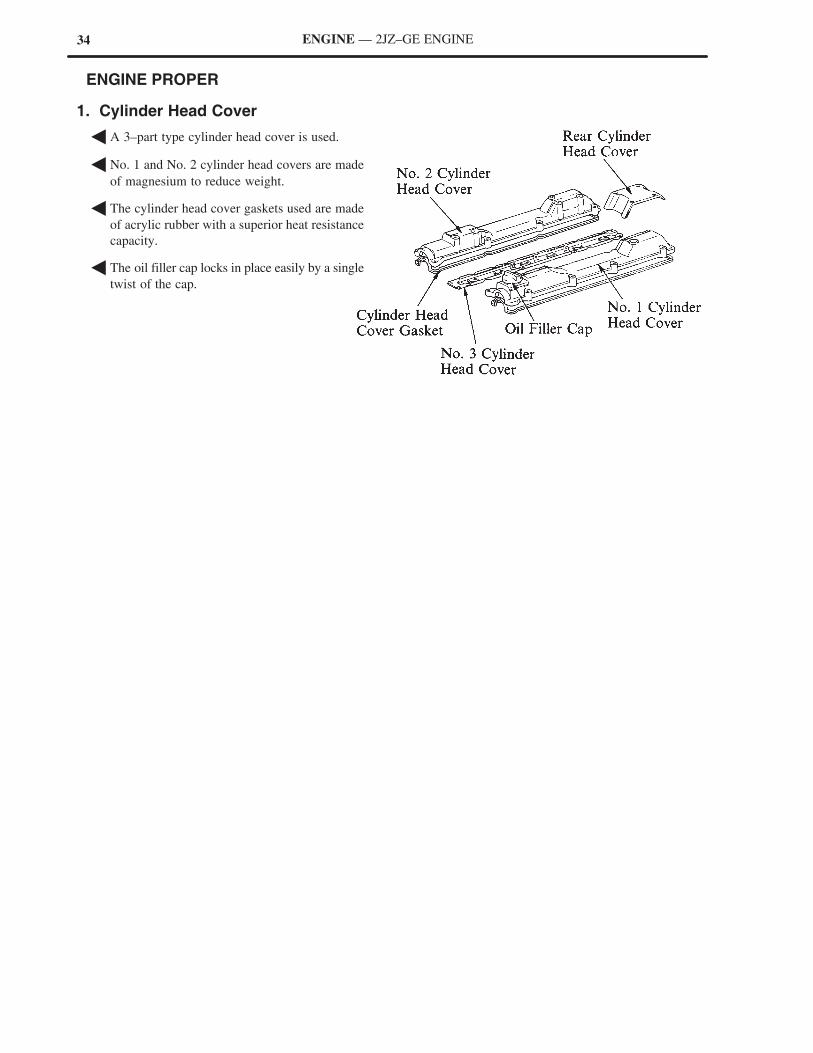
� ENGINE PROPER
1. Cylinder Head Cover
� A 3–part type cylinder head cover is used.
� No. 1 and No. 2 cylinder head covers are made
of magnesium to reduce weight.
� The cylinder head cover gaskets used are made
of acrylic rubber with a superior heat resistance
capacity.
� The oil filler cap locks in place easily by a single
twist of the cap.
35ENGINE — 2JZ–GE ENGINE
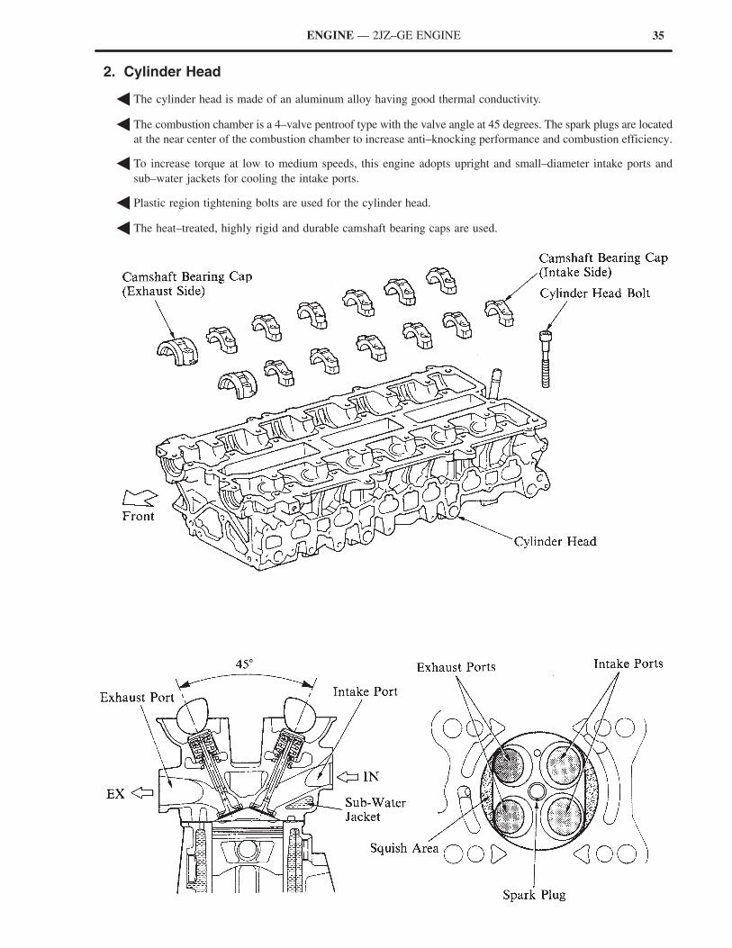
2. Cylinder Head
� The cylinder head is made of an aluminum alloy having good thermal conductivity.
� The combustion chamber is a 4–valve pentroof type with the valve angle at 45 degrees. The spark plugs are located
at the near center of the combustion chamber to increase anti–knocking performance and combustion efficiency.
� To increase torque at low to medium speeds, this engine adopts upright and small–diameter intake ports and
sub–water jackets for cooling the intake ports.
� Plastic region tightening bolts are used for the cylinder head.
� The heat–treated, highly rigid and durable camshaft bearing caps are used.
36 ENGINE — 2JZ–GE ENGINE
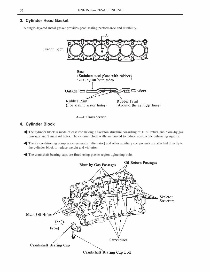
3. Cylinder Head Gasket
A single–layered metal gasket provides good sealing performance and durability.
A—A’ Cross Section
4. Cylinder Block
� The cylinder block is made of cast iron having a skeleton structure consisting of 11 oil return and blow–by gas
passages and 2 main oil holes. The external block walls are curved to reduce noise while enhancing rigidity.
� The air conditioning compressor, generator [alternator] and other auxiliary components are attached directly to
the cylinder block to reduce weight and vibration.
� The crankshaft bearing caps are fitted using plastic region tightening bolts.
37ENGINE — 2JZ–GE ENGINE
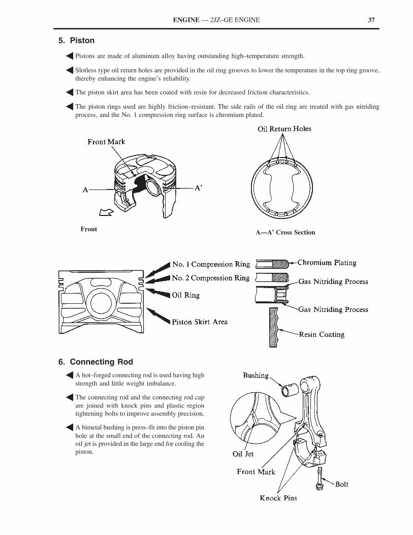
5. Piston
� Pistons are made of aluminum alloy having outstanding high–temperature strength.
� Slotless type oil return holes are provided in the oil ring grooves to lower the temperature in the top ring groove,
thereby enhancing the engine’s reliability.
� The piston skirt area has been coated with resin for decreased friction characteristics.
� The piston rings used are highly friction–resistant. The side rails of the oil ring are treated with gas nitriding
process, and the No. 1 compression ring surface is chromium plated.
A—A’ Cross SectionFront
6. Connecting Rod
� A hot–forged connecting rod is used having high
strength and little weight imbalance.
� The connecting rod and the connecting rod cap
are joined with knock pins and plastic region
tightening bolts to improve assembly precision.
� A bimetal bushing is press–fit into the piston pin
hole at the small end of the connecting rod. An
oil jet is provided in the large end for cooling the
piston.
38 ENGINE — 2JZ–GE ENGINE
7. Crankshaft
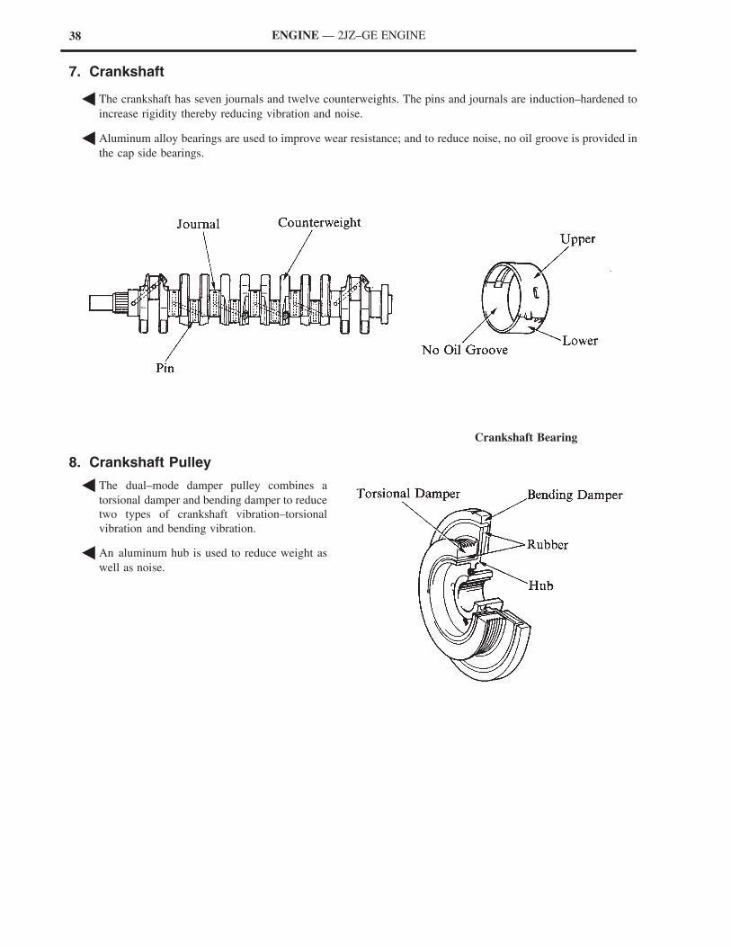
� The crankshaft has seven journals and twelve counterweights. The pins and journals are induction–hardened to
increase rigidity thereby reducing vibration and noise.
� Aluminum alloy bearings are used to improve wear resistance; and to reduce noise, no oil groove is provided in
the cap side bearings.
Crankshaft Bearing
8. Crankshaft Pulley
� The dual–mode damper pulley combines a
torsional damper and bending damper to reduce
two types of crankshaft vibration–torsional
vibration and bending vibration.
� An aluminum hub is used to reduce weight as
well as noise.
39ENGINE — 2JZ–GE ENGINE
� VALVE MECHANISM
1. General
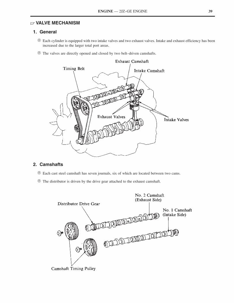
� Each cylinder is equipped with two intake valves and two exhaust valves. Intake and exhaust efficiency has been
increased due to the larger total port areas.
� The valves are directly opened and closed by two belt–driven camshafts.
2. Camshafts
� Each cast steel camshaft has seven journals, six of which are located between two cams.
� The distributor is driven by the drive gear attached to the exhaust camshaft.
40 ENGINE — 2JZ–GE ENGINE
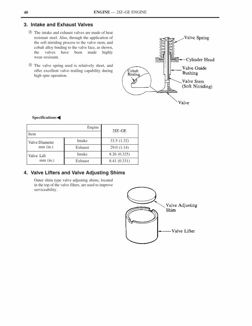
3. Intake and Exhaust Valves
� The intake and exhaust valves are made of heat
resistant steel. Also, through the application of
the soft nitriding process to the valve stem, and
cobalt alloy binding to the valve face, as shown,
the valves have been made highly
wear–resistant.
� The valve spring used is relatively short, and
offer excellent valve–trailing capability during
high rpm operation.
�Specifications�
Engine2JZ GE
Item2JZ–GE
Valve Diameter Intake 33.5 (1.32)Valve Diametermm (in.) Exhaust 29.0 (1.14)
Valve Lift Intake 8.26 (0.325)Valve Liftmm (in.) Exhaust 8.41 (0.331)
4. Valve Lifters and Valve Adjusting Shims
Outer shim type valve adjusting shims, located
in the top of the valve filters, are used to improve
serviceability.
41ENGINE — 2JZ–GE ENGINE
5. Timing Belt
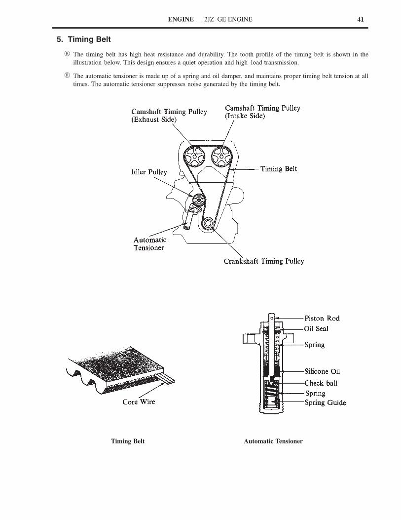
� The timing belt has high heat resistance and durability. The tooth profile of the timing belt is shown in the
illustration below. This design ensures a quiet operation and high–load transmission.
� The automatic tensioner is made up of a spring and oil damper, and maintains proper timing belt tension at all
times. The automatic tensioner suppresses noise generated by the timing belt.
Timing Belt Automatic Tensioner
42 ENGINE — 2JZ–GE ENGINE
� LUBRICATION SYSTEM
1. General
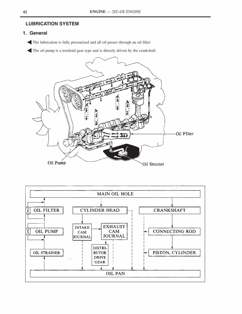
� The lubrication is fully pressurized and all oil passes through an oil filter
� The oil pump is a trochoid gear type and is directly driven by the crankshaft.
43ENGINE — 2JZ–GE ENGINE
2. Oil Pan
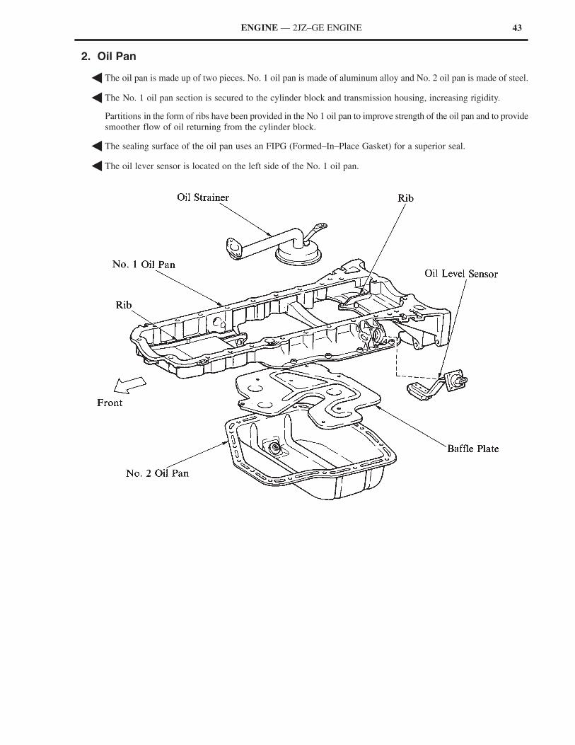
� The oil pan is made up of two pieces. No. 1 oil pan is made of aluminum alloy and No. 2 oil pan is made of steel.
� The No. 1 oil pan section is secured to the cylinder block and transmission housing, increasing rigidity.
Partitions in the form of ribs have been provided in the No 1 oil pan to improve strength of the oil pan and to provide
smoother flow of oil returning from the cylinder block.
� The sealing surface of the oil pan uses an FIPG (Formed–In–Place Gasket) for a superior seal.
� The oil lever sensor is located on the left side of the No. 1 oil pan.
44 ENGINE — 2JZ–GE ENGINE
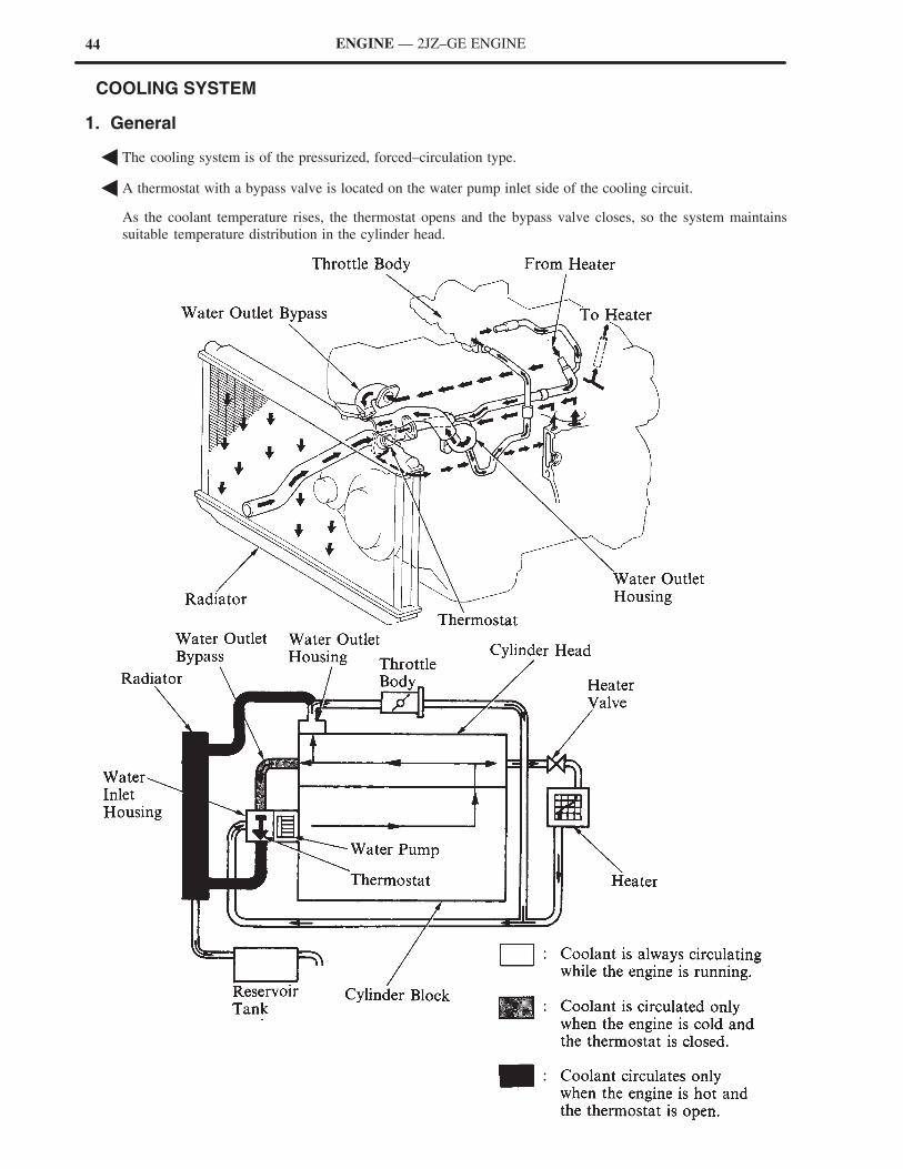
� COOLING SYSTEM
1. General
� The cooling system is of the pressurized, forced–circulation type.
� A thermostat with a bypass valve is located on the water pump inlet side of the cooling circuit.
As the coolant temperature rises, the thermostat opens and the bypass valve closes, so the system maintains
suitable temperature distribution in the cylinder head.
45ENGINE — 2JZ–GE ENGINE
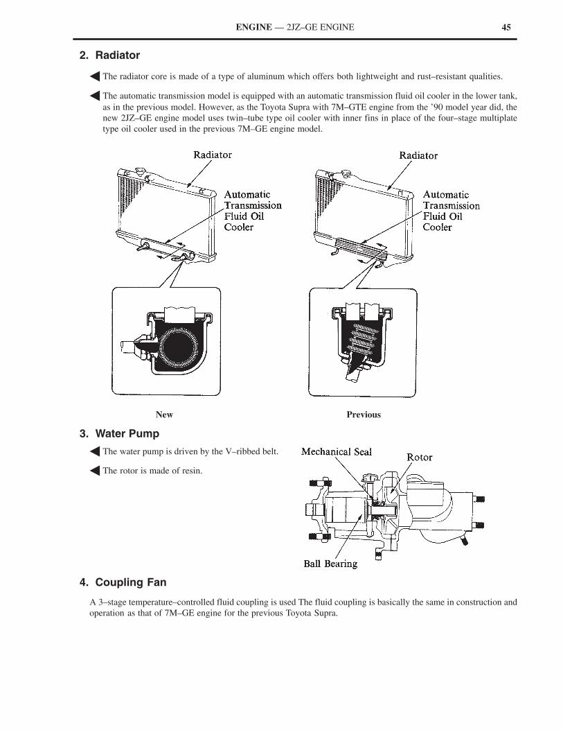
2. Radiator
� The radiator core is made of a type of aluminum which offers both lightweight and rust–resistant qualities.
� The automatic transmission model is equipped with an automatic transmission fluid oil cooler in the lower tank,
as in the previous model. However, as the Toyota Supra with 7M–GTE engine from the ’90 model year did, the
new 2JZ–GE engine model uses twin–tube type oil cooler with inner fins in place of the four–stage multiplate
type oil cooler used in the previous 7M–GE engine model.
New Previous
3. Water Pump
� The water pump is driven by the V–ribbed belt.
� The rotor is made of resin.
4. Coupling Fan
A 3–stage temperature–controlled fluid coupling is used The fluid coupling is basically the same in construction and
operation as that of 7M–GE engine for the previous Toyota Supra.
46 ENGINE — 2JZ–GE ENGINE
� INTAKE AND EXHAUST SYSTEM
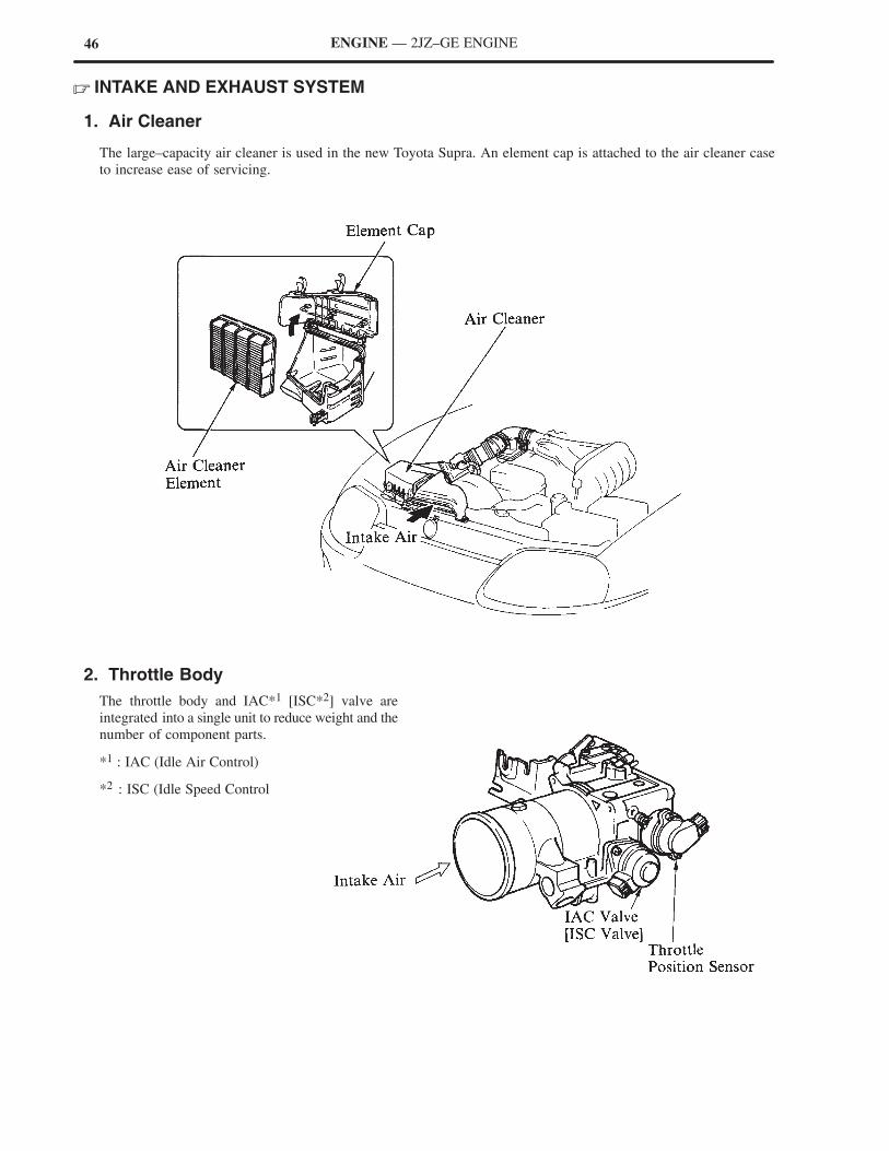
1. Air Cleaner
The large–capacity air cleaner is used in the new Toyota Supra. An element cap is attached to the air cleaner case
to increase ease of servicing.
2. Throttle Body
The throttle body and IAC*1 [ISC*2] valve are
integrated into a single unit to reduce weight and the
number of component parts.
*1 : IAC (Idle Air Control)
*2 : ISC (Idle Speed Control
47ENGINE — 2JZ–GE ENGINE
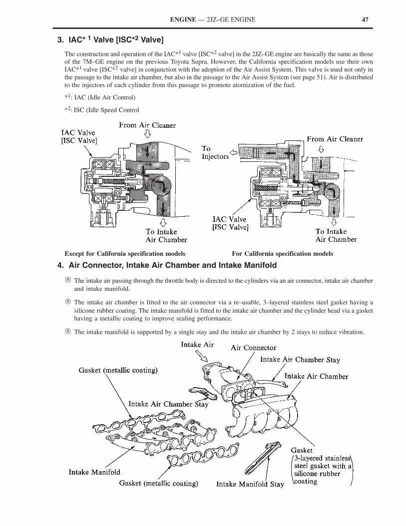
3. IAC* 1 Valve [ISC*2 Valve]
The construction and operation of the IAC*1 valve [ISC*2 valve] in the 2JZ–GE engine are basically the same as those
of the 7M–GE engine on the previous Toyota Supra. However, the California specification models use their own
IAC*1 valve [ISC*2 valve] in conjunction with the adoption of the Air Assist System. This valve is used not only in
the passage to the intake air chamber, but also in the passage to the Air Assist System (see page 51). Air is distributed
to the injectors of each cylinder from this passage to promote atomization of the fuel.
*1: IAC (Idle Air Control)
*2: ISC (Idle Speed Control
Except for California specification models For California specification models
4. Air Connector, Intake Air Chamber and Intake Manifold
� The intake air passing through the throttle body is directed to the cylinders via an air connector, intake air chamber
and intake manifold.
� The intake air chamber is fitted to the air connector via a re–usable, 3–layered stainless steel gasket having a
silicone rubber coating. The intake manifold is fitted to the intake air chamber and the cylinder head via a gasket
having a metallic coating to improve sealing performance.
� The intake manifold is supported by a single stay and the intake air chamber by 2 stays to reduce vibration.
48 ENGINE — 2JZ–GE ENGINE
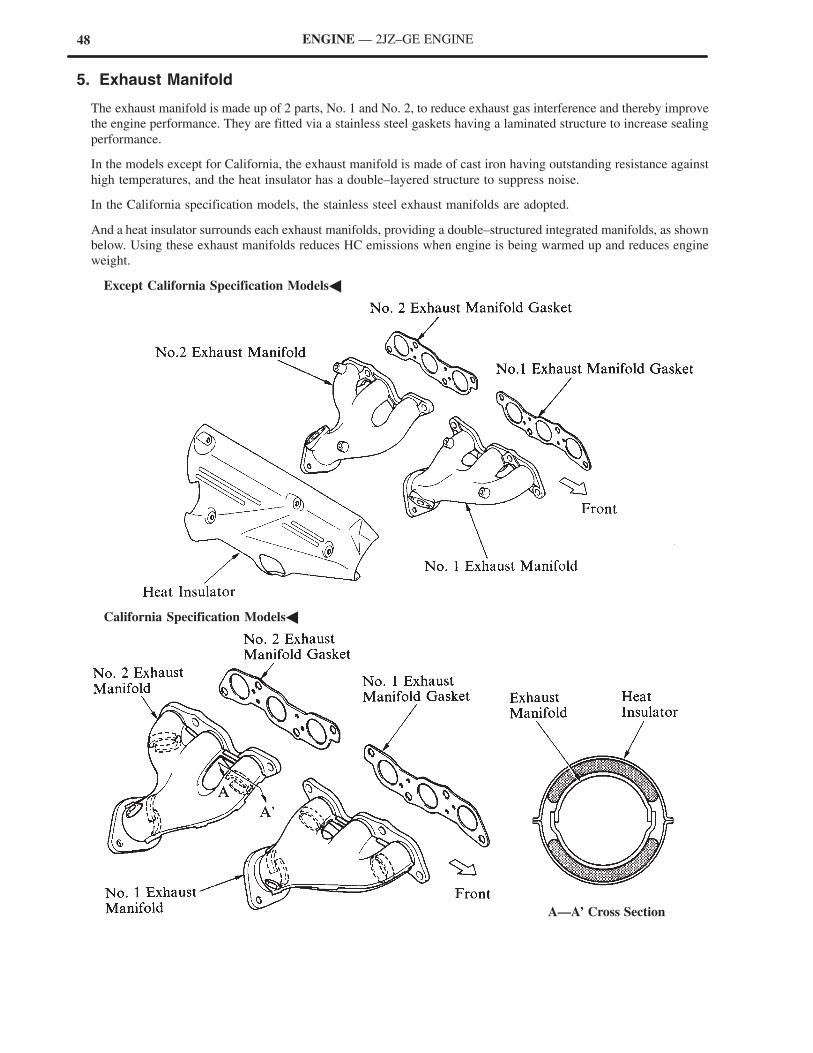
5. Exhaust Manifold
The exhaust manifold is made up of 2 parts, No. 1 and No. 2, to reduce exhaust gas interference and thereby improve
the engine performance. They are fitted via a stainless steel gaskets having a laminated structure to increase sealing
performance.
In the models except for California, the exhaust manifold is made of cast iron having outstanding resistance against
high temperatures, and the heat insulator has a double–layered structure to suppress noise.
In the California specification models, the stainless steel exhaust manifolds are adopted.
And a heat insulator surrounds each exhaust manifolds, providing a double–structured integrated manifolds, as shown
below. Using these exhaust manifolds reduces HC emissions when engine is being warmed up and reduces engine
weight.
�Except California Specification Models�
�California Specification Models�
A—A’ Cross Section
49ENGINE — 2JZ–GE ENGINE
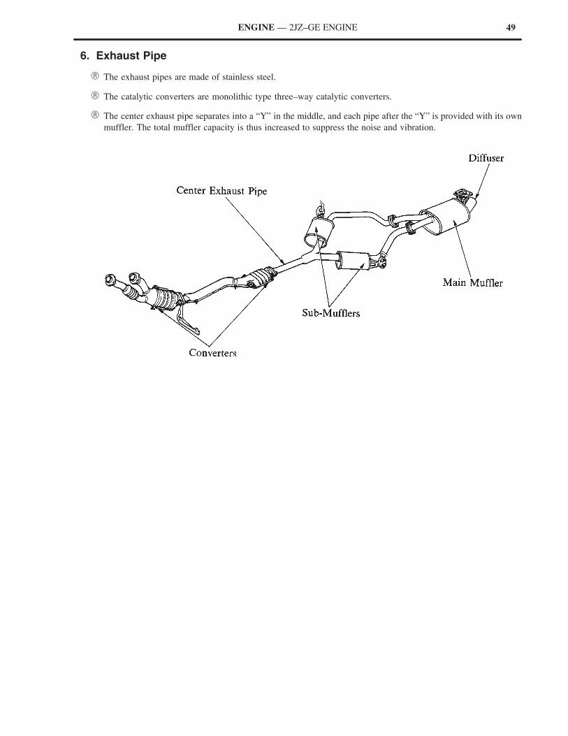
6. Exhaust Pipe
� The exhaust pipes are made of stainless steel.
� The catalytic converters are monolithic type three–way catalytic converters.
� The center exhaust pipe separates into a “Y” in the middle, and each pipe after the “Y” is provided with its own
muffler. The total muffler capacity is thus increased to suppress the noise and vibration.
50 ENGINE — 2JZ–GE ENGINE
� FUEL SYSTEM
1. General
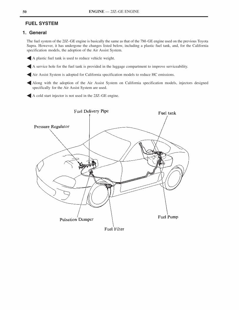
The fuel system of the 2JZ–GE engine is basically the same as that of the 7M–GE engine used on the previous Toyota
Supra. However, it has undergone the changes listed below, including a plastic fuel tank, and, for the California
specification models, the adoption of the Air Assist System.
� A plastic fuel tank is used to reduce vehicle weight.
� A service hole for the fuel tank is provided in the luggage compartment to improve serviceability.
� Air Assist System is adopted for California specification models to reduce HC emissions.
� Along with the adoption of the Air Assist System on California specification models, injectors designed
specifically for the Air Assist System are used.
� A cold start injector is not used in the 2JZ–GE engine.
51ENGINE — 2JZ–GE ENGINE
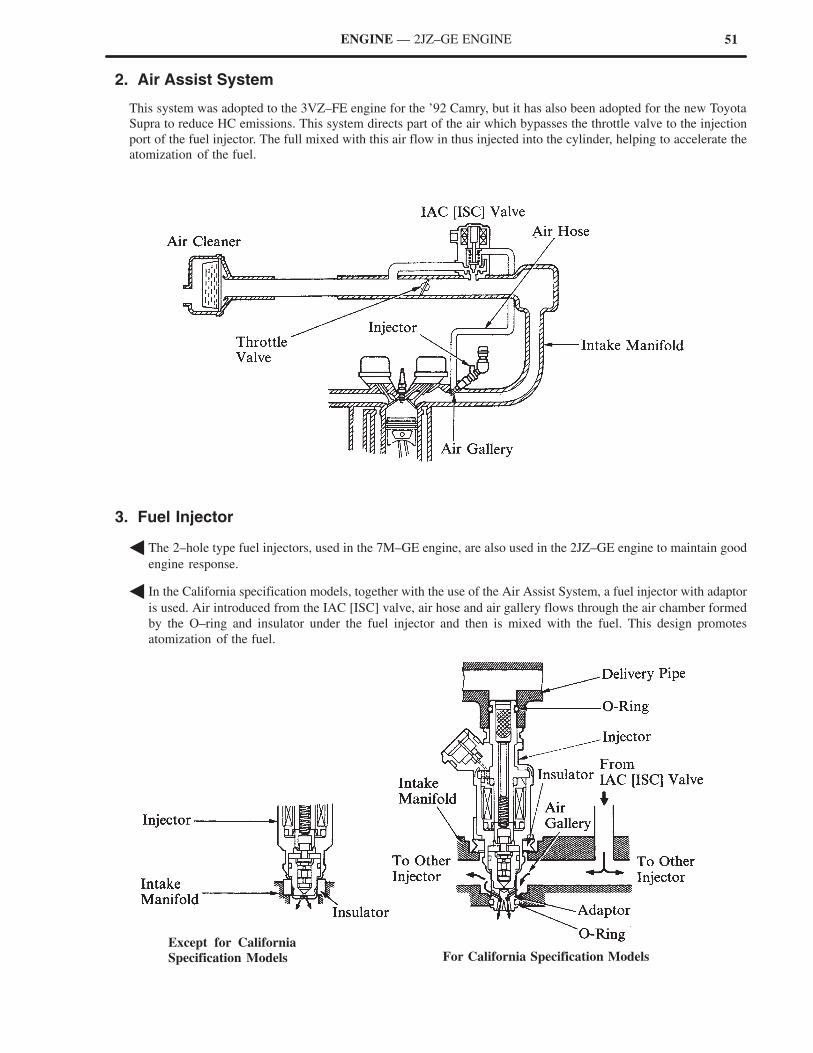
2. Air Assist System
This system was adopted to the 3VZ–FE engine for the ’92 Camry, but it has also been adopted for the new Toyota
Supra to reduce HC emissions. This system directs part of the air which bypasses the throttle valve to the injection
port of the fuel injector. The full mixed with this air flow in thus injected into the cylinder, helping to accelerate the
atomization of the fuel.
3. Fuel Injector
� The 2–hole type fuel injectors, used in the 7M–GE engine, are also used in the 2JZ–GE engine to maintain good
engine response.
� In the California specification models, together with the use of the Air Assist System, a fuel injector with adaptor
is used. Air introduced from the IAC [ISC] valve, air hose and air gallery flows through the air chamber formed
by the O–ring and insulator under the fuel injector and then is mixed with the fuel. This design promotes
atomization of the fuel.
Except for California
Specification Models For California Specification Models
52 ENGINE — 2JZ–GE ENGINE
4. Fuel Tank
� The adoption of a plastic fuel tank greatly improves its rust resistance, and reduces the vehicle weight.
� The serviceability of the fuel tank, fuel pump, and fuel sender gauge has been improved by providing a service
hole in the luggage compartment.
� IGNITION SYSTEM
The ignition system in the 2JZ–GE engine is basically the same as that in the 7M–GE engine for the previous Toyota
Supra.
53
Automatic Tensioner
Automatic Tensioner Cross Section
ENGINE — 2JZ–GE ENGINE
� SERPENTINE BELT DRIVE SYSTEM
1. General
� Accessory components are driven by a ser–
pentine belt consisting of a single V–ribbed belt.
It reduces the overall engine length, weight and
number of engine parts.
� An automatic tensioner eliminates the need for
tension adjustment.
2. Automatic Tensioner
General
The automatic tensioner uses the torsional force of
a coil spring to keep the belt tension constant,
making belt adjustments unnecessary. In addition,
scale marks on the arm and bracket indicate when
the V–ribbed belt must be replaced.
NOTE: New belt— within the “A” range, as
illustrated on the right.
Construction
The automatic tensioner consists of an idler pulley,
arm and bracket. The bracket is mounted on the
engine, and the arm moves on the bracket shaft as
its axis. An idler pulley shaft is integrated at the end
of the arm. The torsion spring exerts force on the
arm, and the idler pulley applies tension to the belt.
54 ENGINE — 2JZ–GE ENGINE
� ENGINE MOUNTING
In the new Toyota Supra, the engine is supported by liquid filled compound mounts fitted on both sides of the engine
to reduce vibration and noise at all speeds as same as the previous model. Aluminum engine brackets also reduce
engine vibration and noise while minimizing the total engine weight.
The current model change features the adoption of an aluminum housing and nylon separator, which helps reduce
weight. In addition, the newly adopted nylon cylinder around the liquid filled chamber, and the orienting of the
chamber towards the engine, help reduce the transfer of engine heat to the insulator rubber. This helps alleviate the
hardening of the rubber material due to heat, and increases its durability.
�Front Engine Mounting Insulator Cross Section�
New Previous
55ENGINE — 2JZ–GE ENGINE
� ENGINE CONTROL SYSTEM
1. General
The engine control system of the 2JZ–GE engine is basically the same in construction and operation as that of the
7M–GE engine for the previous Toyota Supra. However, in automatic transmission models, the ECM*1 [engine ECU]
and PCM*2 [transmission ECU] have been integrated into a single unit of ECM*1 [engine ECU], carrying out overall
control of the engine and automatic transmission. Also to suit the 2JZ–GE engine, the sequential multiport fuel
injection system is adopted.
Comparison of the engine control system between the 2JZ–GE engine and 7M–GE engine is as follows.
*1 : ECM (Engine Control Module)
*2 : PCM (Powertrain Control Module)
System Outline 2JZ–GE 7M–GE
SFI(Sequential Multiport
An L–type SFI [EFI] system directly detects the intake airvolume with an optical Karman–Vortex type volume airflow meter.
—
(Sequential MultiportFuel Injection)[EFI]
An L–type MFI (Multiport Fuel Injection) [EFI] systemdirectly detects the intake air volume with a vane typevolume air flow meter.
—
P 62
The fuel injection system is a sequential multiport fuelinjection system.
—
� Page 62 The fuel injection system is a 3–group type and injects to2 cylinders each.
—
Cold Start InjectorWhen the coolant temperature is low, the injection dura-tion of the cold start injector is controlled by the ECM*1
[engine ECU] and start injector time switch.—
ESA(El i S k
Ignition timing is determined by the engine ECM*1[en-gine ECU] based on signals from various sensors.Corrects ignition timing in response to engine knocking.
(Electronic Spark Advance)
ECM*1 calculates the primary current (ignition coil) ener-gizing start timing.
—
2 knock sensors are used of further improve knock detec-tion.
—
� Page 63 In vehicles equipped with automatic transmission, thetorque control correction during gear shifting has beenused to minimize the shift shock.
—
IACIdle Air Control[ISC]
� Page 66
A step motor type IAC [ISC] system controls the fast idleand idle speeds.
ACIS(Acoustic ControlInduction System)
� Page 67
The intake air passages are switched according to the engine speed and throttle valve opening angle to providehigh performance in all speed ranges.
*2
*1 : ECM (Engine Control Module)
*2 : In the 7M–GE engine, this is called Intake Air Control System
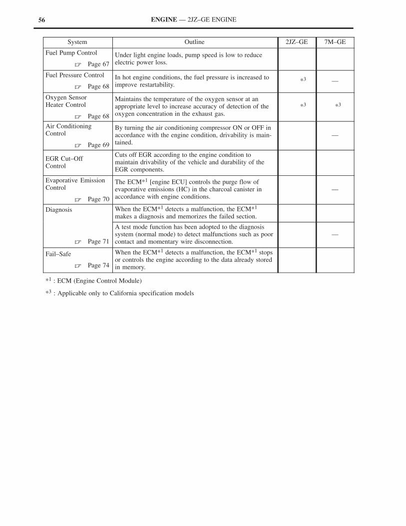
56 ENGINE — 2JZ–GE ENGINE
System Outline 2JZ–GE 7M–GE
Fuel Pump Control
� Page 67
Under light engine loads, pump speed is low to reduceelectric power loss.
Fuel Pressure Control
� Page 68
In hot engine conditions, the fuel pressure is increased toimprove restartability.
*3 —
Oxygen SensorHeater Control
� Page 68
Maintains the temperature of the oxygen sensor at an appropriate level to increase accuracy of detection of theoxygen concentration in the exhaust gas.
*3 *3
Air Conditioning Control
� Page 69
By turning the air conditioning compressor ON or OFF inaccordance with the engine condition, drivability is main-tained.
—
EGR Cut–Off Control
Cuts off EGR according to the engine condition to maintain drivability of the vehicle and durability of theEGR components.
Evaporative EmissionControl
� Page 70
The ECM*1 [engine ECU] controls the purge flow ofevaporative emissions (HC) in the charcoal canister inaccordance with engine conditions.
—
Diagnosis When the ECM*1 detects a malfunction, the ECM*1
makes a diagnosis and memorizes the failed section.
� Page 71
A test mode function has been adopted to the diagnosissystem (normal mode) to detect malfunctions such as poorcontact and momentary wire disconnection.
—
Fail–Safe
� Page 74
When the ECM*1 detects a malfunction, the ECM*1 stopsor controls the engine according to the data already storedin memory.
*1 : ECM (Engine Control Module)
*3 : Applicable only to California specification models
57ENGINE — 2JZ–GE ENGINE
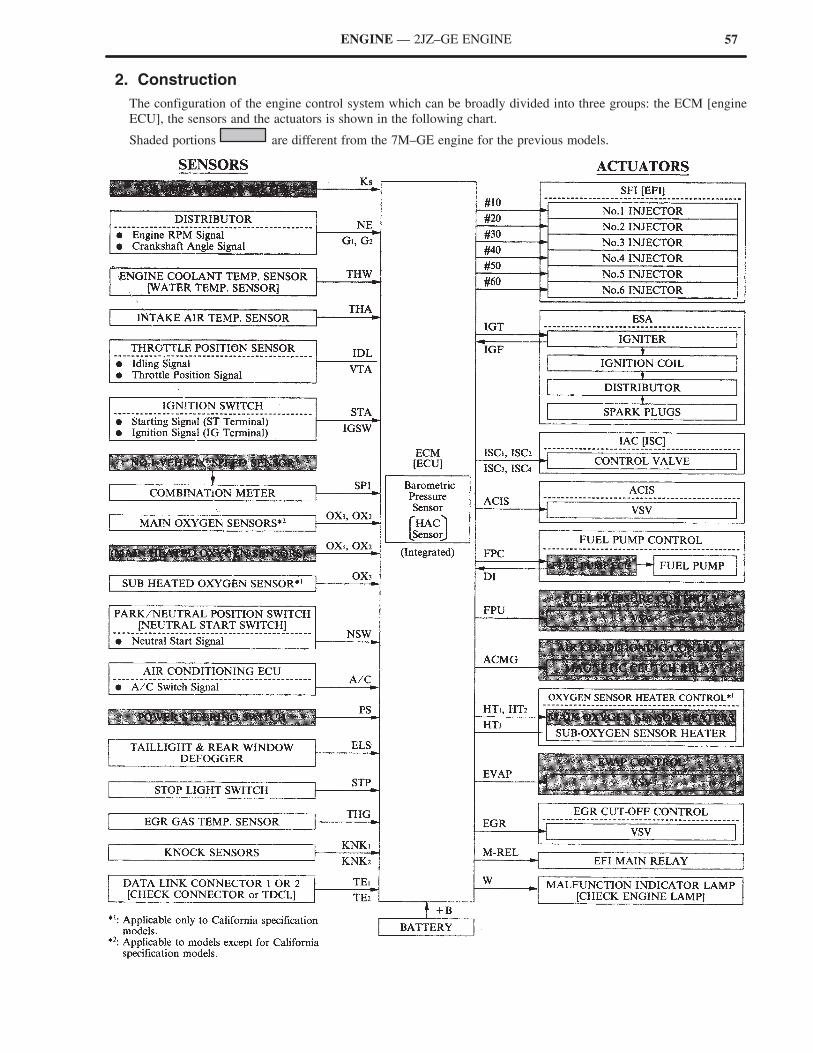
2. Construction
The configuration of the engine control system which can be broadly divided into three groups: the ECM [engine
ECU], the sensors and the actuators is shown in the following chart.
Shaded portions are different from the 7M–GE engine for the previous models.
58
*1 : Applicable only to California specification models.
ENGINE — 2JZ–GE ENGINE
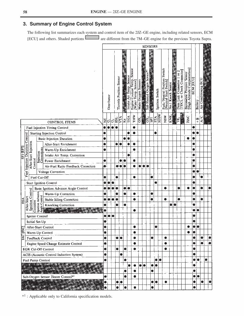
3. Summary of Engine Control System
The following list summarizes each system and control item of the 2JZ–GE engine, including related sensors, ECM
[ECU] and others. Shaded portions are different from the 7M–GE engine for the previous Toyota Supra.
59ENGINE — 2JZ–GE ENGINE
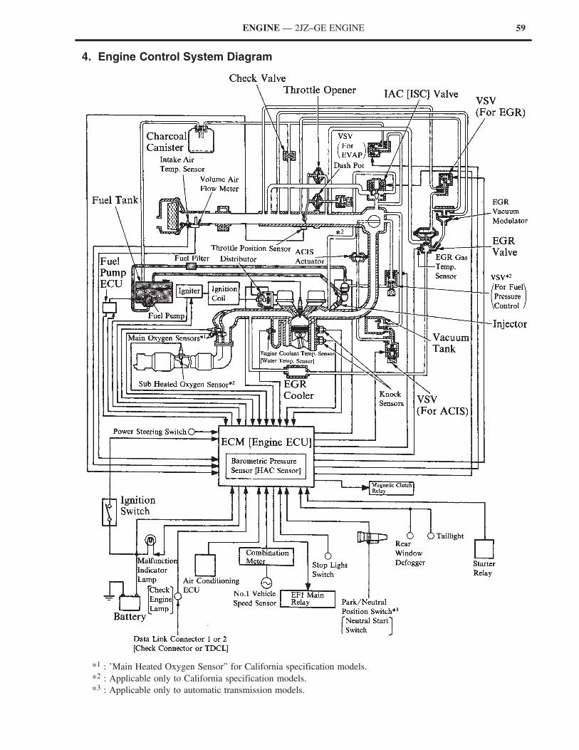
4. Engine Control System Diagram
*1 : ’Main Heated Oxygen Sensor” for California specification models.
*2 : Applicable only to California specification models.
*3 : Applicable only to automatic transmission models.
60 ENGINE — 2JZ–GE ENGINE
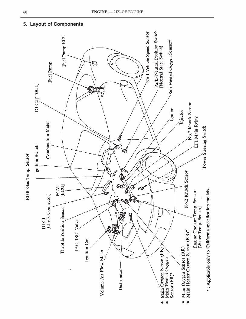
5. Layout of Components
61ENGINE — 2JZ–GE ENGINE
6. Main Components of Engine Control System
General
The following table compares the main components of the 2JZ–GE engine and 7M–GE engine.
Engine2JZ GE 7M GE
Component2JZ–GE 7M–GE
Volume Air Flow Meter Karman–Vortex Type Vane Type
Distributor
Crankshaft Angle Sensor andEngine Speed Sensor
3 Pick–Up Coils ←
Throttle Position Sensor Linear Type ←
Knock SensorBuilt–In Piezoelectric
Type, 2Built–In Piezoelectric
Type, 1
MainWithout Heater Type, 2
Without Heater Type 1Oxygen Sensor
MainWith Heater Type, 2*
Without Heater Type, 1yg
Sub With Heater Type, 1* ←
Injector 2–Hole Type ←
IAC [ISC] Valve Step Motor Type ←
*: Applicable only to California specification models.
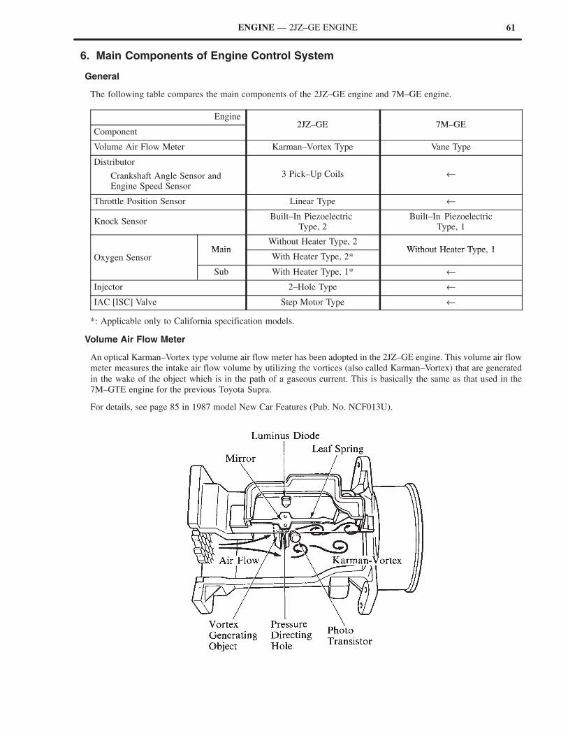
Volume Air Flow Meter
An optical Karman–Vortex type volume air flow meter has been adopted in the 2JZ–GE engine. This volume air flow
meter measures the intake air flow volume by utilizing the vortices (also called Karman–Vortex) that are generated
in the wake of the object which is in the path of a gaseous current. This is basically the same as that used in the
7M–GTE engine for the previous Toyota Supra.
For details, see page 85 in 1987 model New Car Features (Pub. No. NCF013U).
62 ENGINE — 2JZ–GE ENGINE
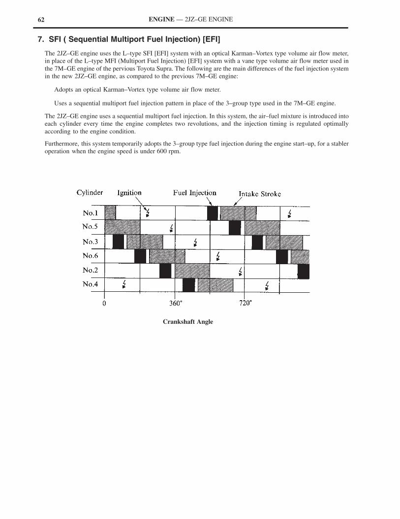
7. SFI ( Sequential Multiport Fuel Injection) [EFI]
The 2JZ–GE engine uses the L–type SFI [EFI] system with an optical Karman–Vortex type volume air flow meter,
in place of the L–type MFI (Multiport Fuel Injection) [EFI] system with a vane type volume air flow meter used in
the 7M–GE engine of the pervious Toyota Supra. The following are the main differences of the fuel injection system
in the new 2JZ–GE engine, as compared to the previous 7M–GE engine:
Adopts an optical Karman–Vortex type volume air flow meter.
Uses a sequential multiport fuel injection pattern in place of the 3–group type used in the 7M–GE engine.
The 2JZ–GE engine uses a sequential multiport fuel injection. In this system, the air–fuel mixture is introduced into
each cylinder every time the engine completes two revolutions, and the injection timing is regulated optimally
according to the engine condition.
Furthermore, this system temporarily adopts the 3–group type fuel injection during the engine start–up, for a stabler
operation when the engine speed is under 600 rpm.
Crankshaft Angle
63
Coolant temperature (THW)
Battery voltage (+B)
Engine speed (NE)
RELEVANT SIGNALS
ENGINE — 2JZ–GE ENGINE
8. ESA (Electronic Spark Advance)
General
The ESA system of the 2JZ–GE engine differs from the system of the 7M–GE engine in the following areas:
In the 2JZ–GE engine, 2 knock sensors are used to further improve knock detection. In addition, torque control
correction has been added to ignition timing control in automatic transmission models.
The ECM* [engine ECU] directly controls the primary current energizing start timing in place of the igniter.
*: ECM (Engine Control Module)
Ignition Timing Control
On the automatic transmission model, a torque control correction has been newly adopted for the ignition timing
control, to reduce the shift shock associated with gear shifting.
1) Torque Control Correction
When the ECM [ECU] judges a gear shift
timing according to signals from various
sensors, it activates the shift control solenoid
valves to perform gear shifting. When the gear
shifting starts, the ECM retards the engine
ignition timing to reduce the engine torque.
As a result, engagement force of the clutches
and brakes of the planetary gear unit is
weakened and the gear shift change is
performed smoothly.
64 ENGINE — 2JZ–GE ENGINE
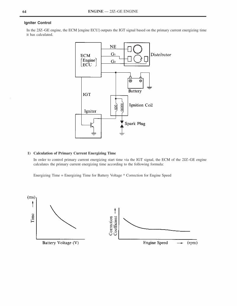
Igniter Control
In the 2JZ–GE engine, the ECM [engine ECU] outputs the IGT signal based on the primary current energizing time
it has calculated.
1) Calculation of Primary Current Energizing Time
In order to control primary current energizing start time via the IGT signal, the ECM of the 2JZ–GE engine
calculates the primary current energizing time according to the following formula:
Energizing Time = Energizing Time for Battery Voltage * Correction for Engine Speed
65ENGINE — 2JZ–GE ENGINE
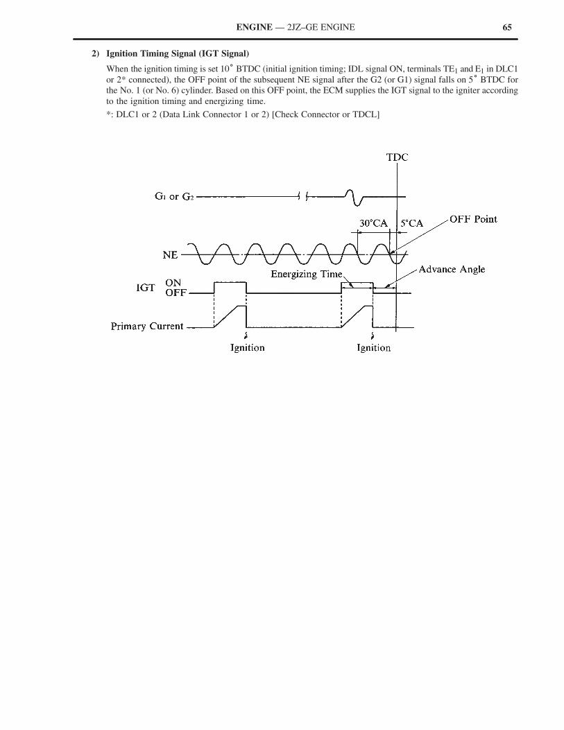
2) Ignition Timing Signal (IGT Signal)
When the ignition timing is set 10° BTDC (initial ignition timing; IDL signal ON, terminals TE1 and E1 in DLC1
or 2* connected), the OFF point of the subsequent NE signal after the G2 (or G1) signal falls on 5° BTDC for
the No. 1 (or No. 6) cylinder. Based on this OFF point, the ECM supplies the IGT signal to the igniter according
to the ignition timing and energizing time.
*: DLC1 or 2 (Data Link Connector 1 or 2) [Check Connector or TDCL]
66 ENGINE — 2JZ–GE ENGINE
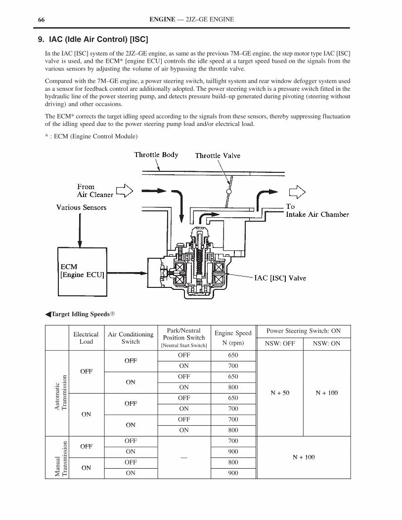
9. IAC (Idle Air Control) [ISC]
In the IAC [ISC] system of the 2JZ–GE engine, as same as the previous 7M–GE engine, the step motor type IAC [ISC]
valve is used, and the ECM* [engine ECU] controls the idle speed at a target speed based on the signals from the
various sensors by adjusting the volume of air bypassing the throttle valve.
Compared with the 7M–GE engine, a power steering switch, taillight system and rear window defogger system used
as a sensor for feedback control are additionally adopted. The power steering switch is a pressure switch fitted in the
hydraulic line of the power steering pump, and detects pressure build–up generated during pivoting (steering without
driving) and other occasions.
The ECM* corrects the target idling speed according to the signals from these sensors, thereby suppressing fluctuation
of the idling speed due to the power steering pump load and/or electrical load.
* : ECM (Engine Control Module)
�Target Idling Speeds�
Electrical Air ConditioningPark/Neutral
Position SwitchEngine Speed Power Steering Switch: ON
ElectricalLoad
Air ConditioningSwitch
Position Switch[Neutral Start Switch]
g p
N (rpm) NSW: OFF NSW: ON
OFFOFF 650
OFF
OFFON 700
OFF
ONOFF 650
ONON 800
N + 50 N + 100
OFFOFF 650
N + 50 N + 100
ON
OFFON 700
ON
ONOFF 700
ONON 800
OFFOFF 700
OFFON 900
N + 100
ONOFF
—800
N + 100
ONON 900
Auto
mat
icT
ransm
issi
on
Man
ual
Tra
nsm
issi
on
67ENGINE — 2JZ–GE ENGINE
10.ACIS (Acoustic Control Induction System)
The ACIS uses a bulkhead to divide the intake air chamber into two stages, with a intake air control valve in the
bulkhead to vary the effective length of the intake manifold. This increases the power output in all ranges from low
to high speeds.
This system is basically the same as the Intake Air Control System of the 7M–GE engine for the previous Toyota
Supra.
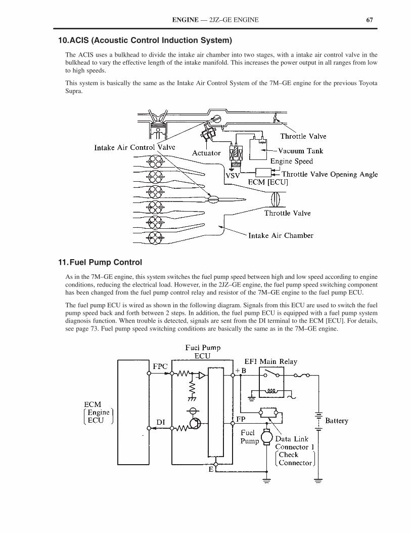
11.Fuel Pump Control
As in the 7M–GE engine, this system switches the fuel pump speed between high and low speed according to engine
conditions, reducing the electrical load. However, in the 2JZ–GE engine, the fuel pump speed switching component
has been changed from the fuel pump control relay and resistor of the 7M–GE engine to the fuel pump ECU.
The fuel pump ECU is wired as shown in the following diagram. Signals from this ECU are used to switch the fuel
pump speed back and forth between 2 steps. In addition, the fuel pump ECU is equipped with a fuel pump system
diagnosis function. When trouble is detected, signals are sent from the DI terminal to the ECM [ECU]. For details,
see page 73. Fuel pump speed switching conditions are basically the same as in the 7M–GE engine.
68
(For Main Oxygen Sensors)
Vehicle speed (SP1)
Intake air volume (Ks)
Engine coolant temperature (THW)
(For Sub Oxygen Sensor)
Intake air volume (Ks)
Engine coolant temperature (THW)
Engine speed (NE)
Battery voltage (+B)
RELEVANT SIGNALS
ENGINE — 2JZ–GE ENGINE
12.Fuel Pressure Control
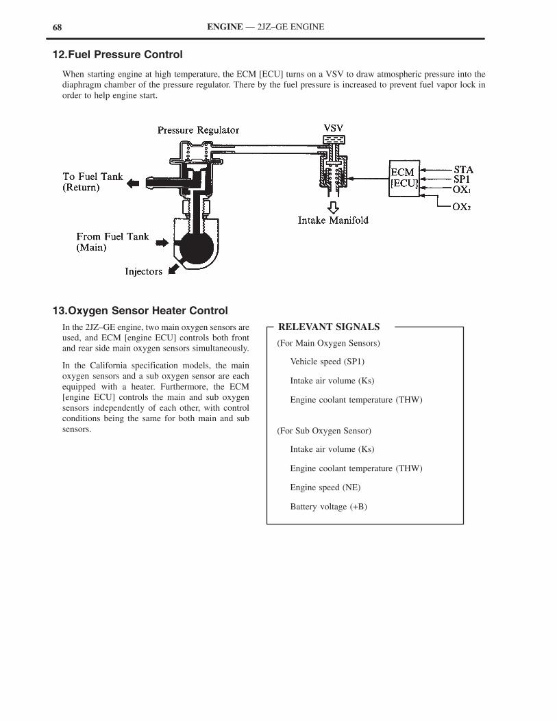
When starting engine at high temperature, the ECM [ECU] turns on a VSV to draw atmospheric pressure into the
diaphragm chamber of the pressure regulator. There by the fuel pressure is increased to prevent fuel vapor lock in
order to help engine start.
13.Oxygen Sensor Heater Control
In the 2JZ–GE engine, two main oxygen sensors are
used, and ECM [engine ECU] controls both front
and rear side main oxygen sensors simultaneously.
In the California specification models, the main
oxygen sensors and a sub oxygen sensor are each
equipped with a heater. Furthermore, the ECM
[engine ECU] controls the main and sub oxygen
sensors independently of each other, with control
conditions being the same for both main and sub
sensors.
69
Park/Neutral position switch
[Neutral start switch] (NSW)
Vehicle speed (SP1)
Throttle position (VTA)
RELEVANT SIGNALS
Park/Neutral position switch
[Neutral start switch] (NSW)
Vehicle speed (SP1)
Throttle position (IDL)
Power steering switch (PS)
RELEVANT SIGNALS
ENGINE — 2JZ–GE ENGINE
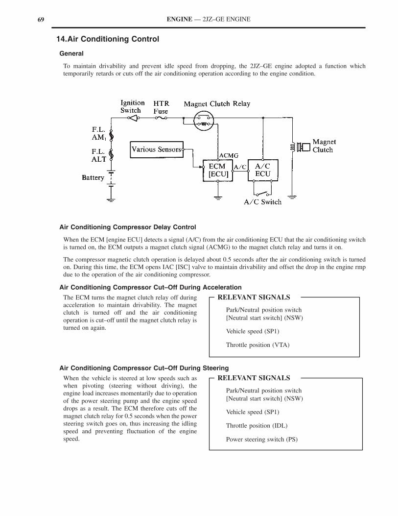
14.Air Conditioning Control
General
To maintain drivability and prevent idle speed from dropping, the 2JZ–GE engine adopted a function which
temporarily retards or cuts off the air conditioning operation according to the engine condition.
Air Conditioning Compressor Delay Control
When the ECM [engine ECU] detects a signal (A/C) from the air conditioning ECU that the air conditioning switch
is turned on, the ECM outputs a magnet clutch signal (ACMG) to the magnet clutch relay and turns it on.
The compressor magnetic clutch operation is delayed about 0.5 seconds after the air conditioning switch is turned
on. During this time, the ECM opens IAC [ISC] valve to maintain drivability and offset the drop in the engine rmp
due to the operation of the air conditioning compressor.
Air Conditioning Compressor Cut–Off During Acceleration
The ECM turns the magnet clutch relay off during
acceleration to maintain drivability. The magnet
clutch is turned off and the air conditioning
operation is cut–off until the magnet clutch relay is
turned on again.
Air Conditioning Compressor Cut–Off During Steering
When the vehicle is steered at low speeds such as
when pivoting (steering without driving), the
engine load increases momentarily due to operation
of the power steering pump and the engine speed
drops as a result. The ECM therefore cuts off the
magnet clutch relay for 0.5 seconds when the power
steering switch goes on, thus increasing the idling
speed and preventing fluctuation of the engine
speed.
70
Throttle position (IDL)
Engine Speed (NE)
Intake air volume (Ks)
Engine coolant temperature (THW)
Vehicle speed (SP1)
RELEVANT SIGNALS
ENGINE — 2JZ–GE ENGINE
15.Evaporative Emission Control
General
The evaporative emission control is a system which utilizes the intake manifold vacuum to draw the evaporative
emissions into the intake air chamber and mix them in with the intake air. The 2JZ–GE engine has adopted a
duty–cycle type VSV (Vacuum Switching Valve) controlled by the ECM [engine ECU] to purge the evaporative
emissions from the charcoal canister.
Construction and Operation
1) Construction
a. VSV
The VSV consists of a coil and a valve. This
valve is normally close type, so the valve is
attached (opened) when current flows to the
coil. The action of turning the coil on and off
is carried out at high speeds. By changing the
duty ratio* of the on and off cycle, the amount
the valve is open is adjusted, thus changing the
amount of air that passes through.
*: The duty ratio is the ratio of the interval
during which current flows in one cycle of
a signal. The figure on the right shows one
cycle during which current flows and then
does not flow.
2) Operation
Purge port A is connected to the charcoal
canister via the check valve. When the throttle
valve opens, manifold pressure is applied to
port A, drawing the evaporative emissions
purged by the charcoal canister. Purge port B is
connected to the charcoal canister via the VSV.
If the engine operating condition reaches predetermined parameters, the ECM [ECU] sends current to the VSV
and the valve opens, thus purging the evaporative emissions.
71ENGINE — 2JZ–GE ENGINE
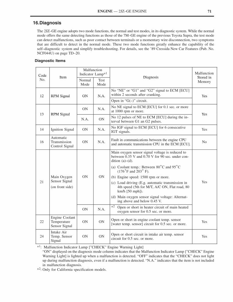
16.Diagnosis
The 2JZ–GE engine adopts two mode functions, the normal and test modes, in its diagnostic system. While the normal
mode offers the same detecting functions as those of the 7M–GE engine of the previous Toyota Supra, the test mode
can detect malfunctions, such as poor contact between terminals or a momentary wire disconnection, two symptoms
that are difficult to detect in the normal mode. These two mode functions greatly enhance the capability of the
self–diagnostic system and simplify troubleshooting. For details, see the ’89 Cressida New Car Features (Pub. No.
NCF044U) on page TD–20.
Diagnostic Items
CodeItem
Malfunction Indicator Lamp*1
DiagnosisMalfunction
Stored inCodeNo.
ItemNormalMode
TestMode
Diagnosis Stored inMemory
12 RPM Signal ON N.A.
No “NE” or “G1” and “G2” signal to ECM [ECU]within 2 seconds after cranking. Yes12 RPM Signal ON N.A.
Open in “G(–)” circuit.
Yes
13 RPM Signal
ON N.A.No NE signal to ECM [ECU] for 0.1 sec. or moreat 1000 rpm or more.
Yes13 RPM Signal
N.A. ONNo 12 pulses of NE to ECM [ECU] during the in-terval between G1 an G2 pulses.
Yes
14 Ignition Signal ON N.A.No IGF signal to ECM [ECU] for 6 consecutiveIGT signals.
Yes
16AutomaticTransmissionControl Signal
ON N.A.Fault in communications between the engine CPUand automatic transmission CPU in the ECM [ECU].
No
21
Main OxygenSensor Signal
(on front side)
ON ON
Main oxygen sensor signal voltage is reduced tobetween 0.35 V and 0.70 V for 90 sec. under con-dition (a)–(d).
(a) Coolant temp.: Between 80°C and 95°C(176°F and 203° F).
(b) Engine speed: 1500 rpm or more.
(c) Load driving (E.g. automatic transmission in4th speed (5th for M/T, A/C ON, Flat road, 80km/h [50 mph]).
(d) Main oxygen sensor signal voltage: Alternat-ing above and below 0.45 V.
Yes
ON N.A.*2 Open or short in heater circuit of main heated
oxygen sensor for 0.5 sec. or more.
22Engine CoolantTemperatureSensor Signal
ON ONOpen or short in engine coolant temp. sensor [water temp. sensor] circuit for 0.5 sec. or more.
Yes
24Intake AirTemp. SensorSignal
ON ONOpen or short circuit in intake air temp. sensorcircuit for 0.5 sec. or more.
Yes
*1: Malfunction Indicator Lamp [”CHECK” Engine Warning Light]
“ON” displayed on the diagnosis mode column indicates that the Malfunction Indicator Lamp [”CHECK” Engine
Warning Light] is lighted up when a malfunction is detected. “OFF” indicates that the “CHECK” does not light
up during malfunction diagnosis, even if a malfunction is detected. “N.A.” indicates that the item is not included
in malfunction diagnosis.
*2: Only for California specification models.
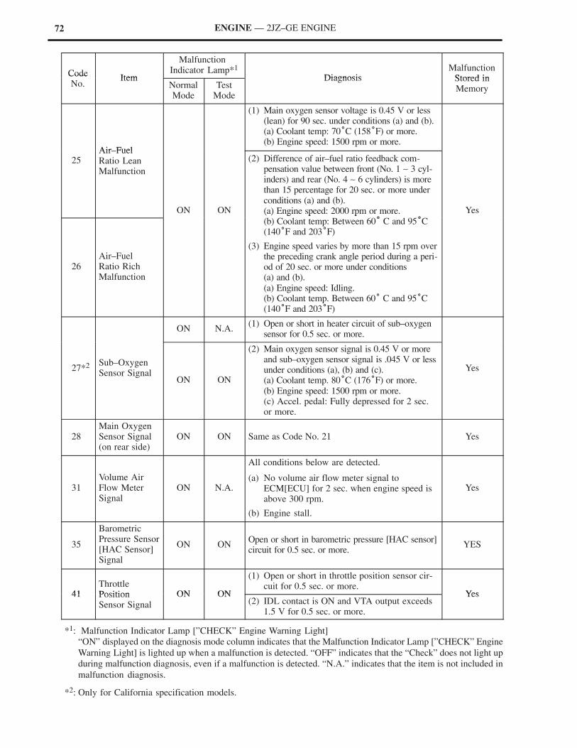
72 ENGINE — 2JZ–GE ENGINE
CodeItem
MalfunctionIndicator Lamp*1
DiagnosisMalfunction
Stored inCodeNo.
ItemNormalMode
TestMode
Diagnosis Stored inMemory
Air Fuel
(1) Main oxygen sensor voltage is 0.45 V or less(lean) for 90 sec. under conditions (a) and (b).(a) Coolant temp: 70°C (158°F) or more.(b) Engine speed: 1500 rpm or more.
25Air–FuelRatio LeanMalfunction
ON ON
(2) Difference of air–fuel ratio feedback com-pensation value between front (No. 1 ∼ 3 cyl-inders) and rear (No. 4 ∼ 6 cylinders) is morethan 15 percentage for 20 sec. or more underconditions (a) and (b).(a) Engine speed: 2000 rpm or more.
° °
Yes
26Air–FuelRatio RichMalfunction
( ) g p p(b) Coolant temp: Between 60° C and 95°C(140°F and 203°F)
(3) Engine speed varies by more than 15 rpm overthe preceding crank angle period during a peri-od of 20 sec. or more under conditions (a) and (b).(a) Engine speed: Idling.(b) Coolant temp. Between 60° C and 95°C(140°F and 203°F)
ON N.A.(1) Open or short in heater circuit of sub–oxygen
sensor for 0.5 sec. or more.
27*2 Sub–OxygenSensor Signal
ON ON
(2) Main oxygen sensor signal is 0.45 V or moreand sub–oxygen sensor signal is .045 V or lessunder conditions (a), (b) and (c).(a) Coolant temp. 80°C (176°F) or more.(b) Engine speed: 1500 rpm or more.(c) Accel. pedal: Fully depressed for 2 sec.or more.
Yes
28Main OxygenSensor Signal(on rear side)
ON ON Same as Code No. 21 Yes
31Volume AirFlow MeterSignal
ON N.A.
All conditions below are detected.
(a) No volume air flow meter signal toECM[ECU] for 2 sec. when engine speed isabove 300 rpm.
(b) Engine stall.
Yes
35
BarometricPressure Sensor[HAC Sensor]Signal
ON ONOpen or short in barometric pressure [HAC sensor]circuit for 0.5 sec. or more.
YES
41ThrottlePosition ON ON
(1) Open or short in throttle position sensor cir-cuit for 0.5 sec. or more.
Yes41 PositionSensor Signal
ON ON(2) IDL contact is ON and VTA output exceeds
1.5 V for 0.5 sec. or more.
Yes
*1: Malfunction Indicator Lamp [”CHECK” Engine Warning Light]
“ON” displayed on the diagnosis mode column indicates that the Malfunction Indicator Lamp [”CHECK” Engine
Warning Light] is lighted up when a malfunction is detected. “OFF” indicates that the “Check” does not light up
during malfunction diagnosis, even if a malfunction is detected. “N.A.” indicates that the item is not included in
malfunction diagnosis.
*2: Only for California specification models.

73ENGINE — 2JZ–GE ENGINE
CodeItem
MalfunctionIndicator Lamp*1
DiagnosisMalfunction
Stored inCodeNo.
ItemNormalMode
TestMode
Diagnosis Stored inMemory
42
No. 1 VehicleSpeed SensorSignal(for ECT)
OFF OFF
All conditions below are detected continuouslyfor 8 sec. or more.
(a) Vehicle speed signal: 0 pulses
(b) Engine speed: 3000 rpm or more
(c) Park/neutral position switch[Neutral start switch] (NSW): OFF
(d) Stop light switch: OFFYes42
No. 1 VehicleSpeed SensorSignal(for M/T)
OFF OFF
All conditions below are detected continuouslyfor 8 sec. or more.
(a) Vehicle speed signal: 0 pulses
(b) Engine speed: Between 2000 rpm and 5000rpm.
(c) Coolant temp: Between 80°C (176°F) or more.
(d) Load applied
Yes
43 Starter Signal N.A OFF No starter signal to ECM [ECU]. No
52No. 1 KnockSensor Signal
ON N.A.No No. 1 knock sensor signal to ECM [ECU] for4 crank revolutions with engine speed between1600 rpm ∼ 5200 rpm.
Yes
53KnockControl Signal
ON N.A.Engine control computer (for knock control)malfunctions at engine speed between 650 rpmand 5200 rpm.
Yes
55No. 2 KnockSensor Signal
ON N.A.No No. 2 knock sensor signal to ECM [ECU] for4 crank revolutions with engine speed between1600 rpm ∼ 5200 rpm.
Yes
71EGR SystemMalfunction
ON ON
EGR gas temp. is 70°C (158°F) or below for 1 ∼4 min. under conditions (a) or (b).
(a) Coolant temp: 63°C (145°F) or more.
(b) EGR operation possible (E.g. automatic trans-mission in 3rd speed (5th for M/T), A/C ON,96 km/h [60 mph], flat road).
Yes
(1) Open or short in fuel pump circuit for 1 sec.or more with engine speed 1000 rpm or less.
78Fuel PumpControl Signal
N.A. ON
(2) Open in input circuit of fuel pump ECU(FPC) with engine speed 1000 rpm or less. Yes
Control Signal(3) Open or short in diagnostic signal line (DI)
of fuel pump ECU with engine speed 1000rpm or less.
51SwitchConditionSignal
N.A. OFF
(1) 3 sec. or more after engine starts, idle switch[closed throttle position switch]. OFF (IDL).
(2) Park/neutral position switch [Neutral startswitch] OFF (NSW). (Shift position in “R”,“D”, “2”, or “L” ranges).
(3) A/C switch ON.
No
*1: Malfunction Indicator Lamp [”CHECK” Engine Warning Light]
“ON” displayed on the diagnosis mode column indicates that the Malfunction Indicator Lamp [”CHECK” Engine
Warning Light] is lighted up when a malfunction is detected. “OFF” indicates that the “CHECK” does not light
up during malfunction diagnosis, even if a malfunction is detected. “N.A.” indicates that the item is not included
in malfunction diagnosis.
74 ENGINE — 2JZ–GE ENGINE
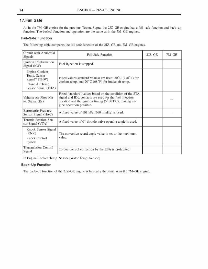
17.Fail Safe
As in the 7M–GE engine for the previous Toyota Supra, the 2JZ–GE engine has a fail–safe function and back–up
function. The basical function and operation are the same as in the 7M–GE engines.
Fail–Safe Function
The following table compares the fail safe function of the 2JZ–GE and 7M–GE engines.
Circuit with AbnormalSignals
Fail Safe Function 2JZ–GE 7M–GE
Ignition ConfirmationSignal (IGF)
Fuel injection is stopped.
Engine Coolant
Temp. Sensor Signal* (THW)
Intake Air Temp.
Sensor Signal (THA)
Fixed values(standard values) are used; 80°C (176°F) forcoolant temp. and 20°C (68°F) for intake air temp.
Volume Air Flow Me-ter Signal (Ks)
Fixed (standard) values based on the condition of the STAsignal and IDL contacts are used for the fuel injectionduration and the ignition timing (5°BTDC), making en-gine operation possible.
—
Barometric PressureSensor Signal (HAC)
A fixed value of 101 kPa (760 mmHg) is used. —
Throttle Position Sen-sor Signal (VTA)
A fixed value of 0° throttle valve opening angle is used.
Knock Sensor Signal
(KNK)
Knock Control
System
The corrective retard angle value is set to the maximumvalue.
Transmission ControlSignal
Torque control correction by the ESA is prohibited.
*: Engine Coolant Temp. Sensor [Water Temp. Sensor]
Back–Up Function
The back–up function of the 2JZ–GE engine is basically the same as in the 7M–GE engine.
75ENGINE — 2JZ–GE ENGINE
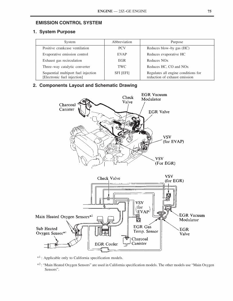
� EMISSION CONTROL SYSTEM
1. System Purpose
System Abbreviation Purpose
Positive crankcase ventilation PCV Reduces blow–by gas (HC)
Evaporative emission control EVAP Reduces evaporative HC
Exhaust gas recirculation EGR Reduces NOx
Three–way catalytic converter TWC Reduces HC, CO and NOx
Sequential multiport fuel injection[Electronic fuel injection]
SFI [EFI] Regulates all engine conditions forreduction of exhaust emission
2. Components Layout and Schematic Drawing
*1 : Applicable only to California specification models.
*2 : “Main Heated Oxygen Sensors” are used in California specification models. The other models use “Main Oxygen
Sensors”.
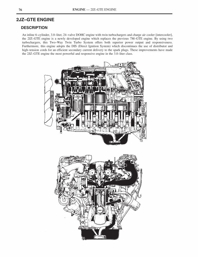
76 ENGINE — 2JZ–GTE ENGINE
2JZ–GTE ENGINE
� DESCRIPTION
An inline 6–cylinder, 3.0–liter, 24–valve DOHC engine with twin turbochargers and charge air cooler [intercooler],
the 2JZ–GTE engine is a newly developed engine which replaces the previous 7M–GTE engine. By using two
turbochargers, this Two–Way Twin Turbo System offers both superior power output and responsiveness.
Furthermore, this engine adopts the DIS (Direct Ignition System) which discontinues the use of distributor and
high–tension cords for an efficient secondary current delivery to the spark plugs. These improvements have made
the 2JZ–GTE engine the most powerful and responsive engine in the 3.0–liter class.
77ENGINE — 2JZ–GTE ENGINE
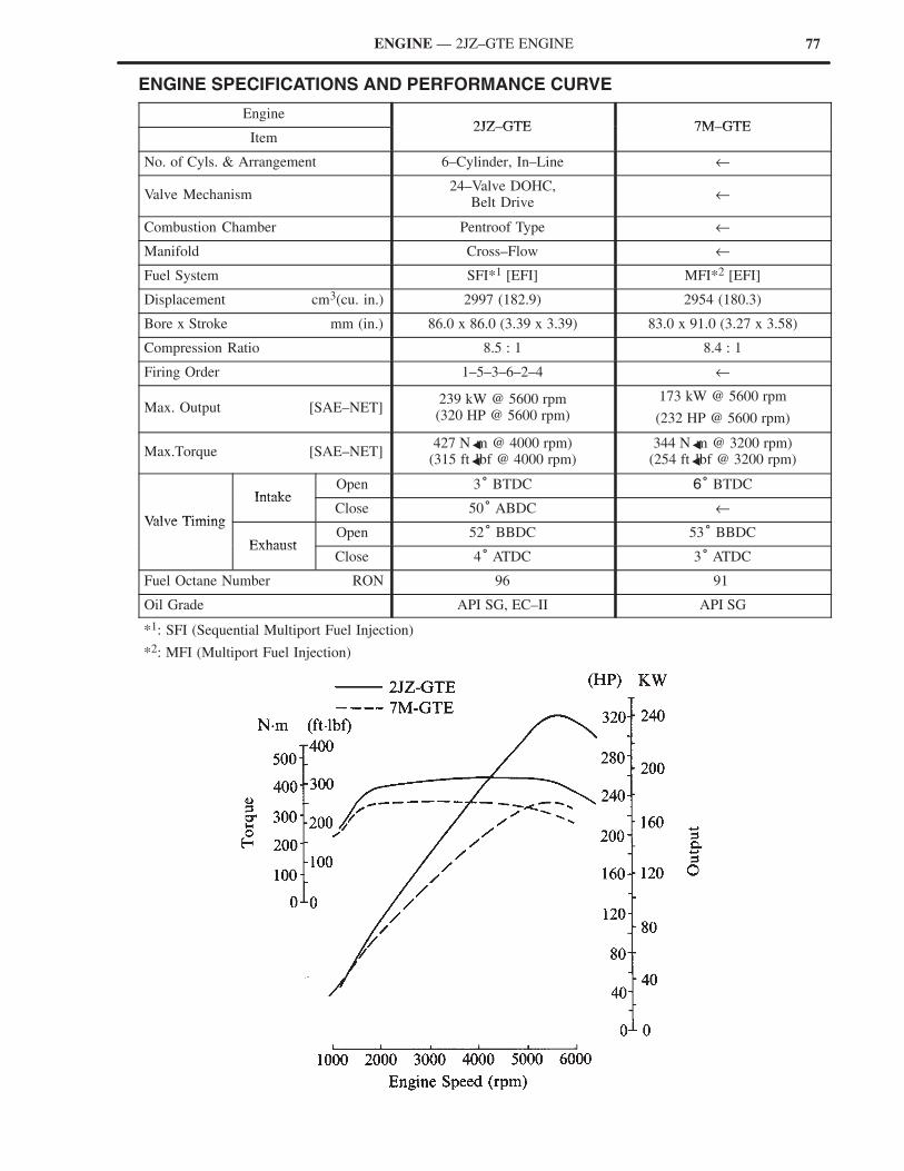
� ENGINE SPECIFICATIONS AND PERFORMANCE CURVE
Engine2JZ GTE 7M GTE
Item2JZ–GTE 7M–GTE
No. of Cyls. & Arrangement 6–Cylinder, In–Line ←
Valve Mechanism24–Valve DOHC,
Belt Drive←
Combustion Chamber Pentroof Type ←
Manifold Cross–Flow ←
Fuel System SFI*1 [EFI] MFI*2 [EFI]
Displacement cm3(cu. in.) 2997 (182.9) 2954 (180.3)
Bore x Stroke mm (in.) 86.0 x 86.0 (3.39 x 3.39) 83.0 x 91.0 (3.27 x 3.58)
Compression Ratio 8.5 : 1 8.4 : 1
Firing Order 1–5–3–6–2–4 ←
Max. Output [SAE–NET]239 kW @ 5600 rpm(320 HP @ 5600 rpm)
173 kW @ 5600 rpm
(232 HP @ 5600 rpm)
Max.Torque [SAE–NET]427 N �m @ 4000 rpm)
(315 ft �lbf @ 4000 rpm)344 N �m @ 3200 rpm)
(254 ft �lbf @ 3200 rpm)
IntakeOpen 3° BTDC 6° BTDC
Valve Timing
IntakeClose 50° ABDC ←
Valve Timing
ExhaustOpen 52° BBDC 53° BBDC
ExhaustClose 4° ATDC 3° ATDC
Fuel Octane Number RON 96 91
Oil Grade API SG, EC–II API SG
*1: SFI (Sequential Multiport Fuel Injection)
*2: MFI (Multiport Fuel Injection)
78 ENGINE — 2JZ–GTE ENGINE
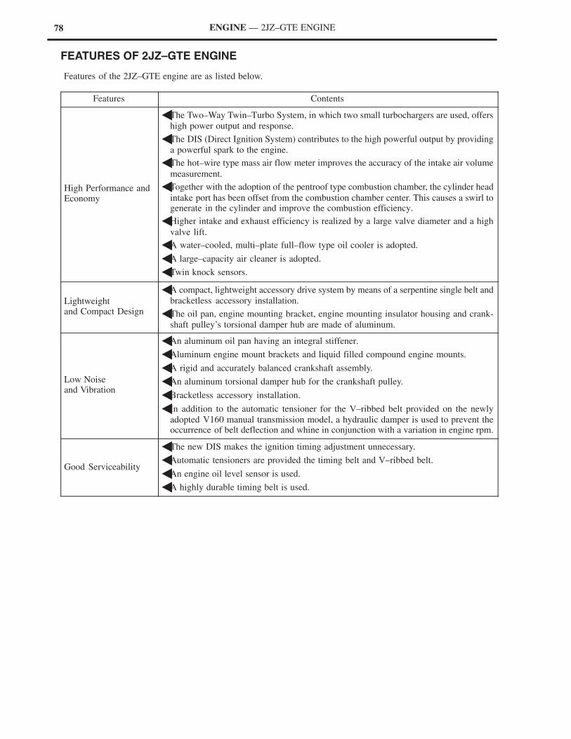
� FEATURES OF 2JZ–GTE ENGINE
Features of the 2JZ–GTE engine are as listed below.
Features Contents
High Performance andEconomy
�The Two–Way Twin–Turbo System, in which two small turbochargers are used, offers
high power output and response.
�The DIS (Direct Ignition System) contributes to the high powerful output by providing
a powerful spark to the engine.
�The hot–wire type mass air flow meter improves the accuracy of the intake air volume
measurement.
�Together with the adoption of the pentroof type combustion chamber, the cylinder head
intake port has been offset from the combustion chamber center. This causes a swirl togenerate in the cylinder and improve the combustion efficiency.
�Higher intake and exhaust efficiency is realized by a large valve diameter and a high
valve lift.
�A water–cooled, multi–plate full–flow type oil cooler is adopted.
�A large–capacity air cleaner is adopted.
�Twin knock sensors.
Lightweightand Compact Design
�A compact, lightweight accessory drive system by means of a serpentine single belt and
bracketless accessory installation.
�The oil pan, engine mounting bracket, engine mounting insulator housing and crank-
shaft pulley’s torsional damper hub are made of aluminum.
Low Noise and Vibration
�An aluminum oil pan having an integral stiffener.
�Aluminum engine mount brackets and liquid filled compound engine mounts.
�A rigid and accurately balanced crankshaft assembly.
�An aluminum torsional damper hub for the crankshaft pulley.
�Bracketless accessory installation.
�In addition to the automatic tensioner for the V–ribbed belt provided on the newly
adopted V160 manual transmission model, a hydraulic damper is used to prevent theoccurrence of belt deflection and whine in conjunction with a variation in engine rpm.
Good Serviceability
�The new DIS makes the ignition timing adjustment unnecessary.
�Automatic tensioners are provided the timing belt and V–ribbed belt.
�An engine oil level sensor is used.
�A highly durable timing belt is used.
79ENGINE — 2JZ–GTE ENGINE
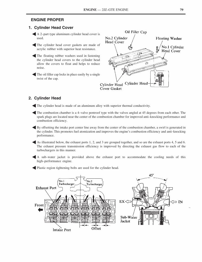
� ENGINE PROPER
1. Cylinder Head Cover
� A 2–part type aluminum cylinder head cover is
used.
� The cylinder head cover gaskets are made of
acrylic rubber with superior heat resistance.
� The floating rubber washers used in fastening
the cylinder head covers to the cylinder head
allow the covers to float and helps to reduce
noise.
� The oil filler cap locks in place easily by a single
twist of the cap.
2. Cylinder Head
� The cylinder head is made of an aluminum alloy with superior thermal conductivity.
� The combustion chamber is a 4–valve pentroof type with the valves angled at 45 degrees from each other. The
spark plugs are located near the center of the combustion chamber for improved anti–knocking performance and
combustion efficiency.
� By offsetting the intake port center line away from the center of the combustion chamber, a swirl is generated in
the cylinder. This promotes fuel atomization and improves the engine’s combustion efficiency and anti–knocking
performance.
� As illustrated below, the exhaust ports 1, 2, and 3 are grouped together, and so are the exhaust ports 4, 5 and 6.
The exhaust pressure transmission efficiency is improved by directing the exhaust gas flow to each of the
turbochargers in this manner.
� A sub–water jacket is provided above the exhaust port to accommodate the cooling needs of this
high–performance engine.
� Plastic region tightening bolts are used for the cylinder head.
80 ENGINE — 2JZ–GTE ENGINE
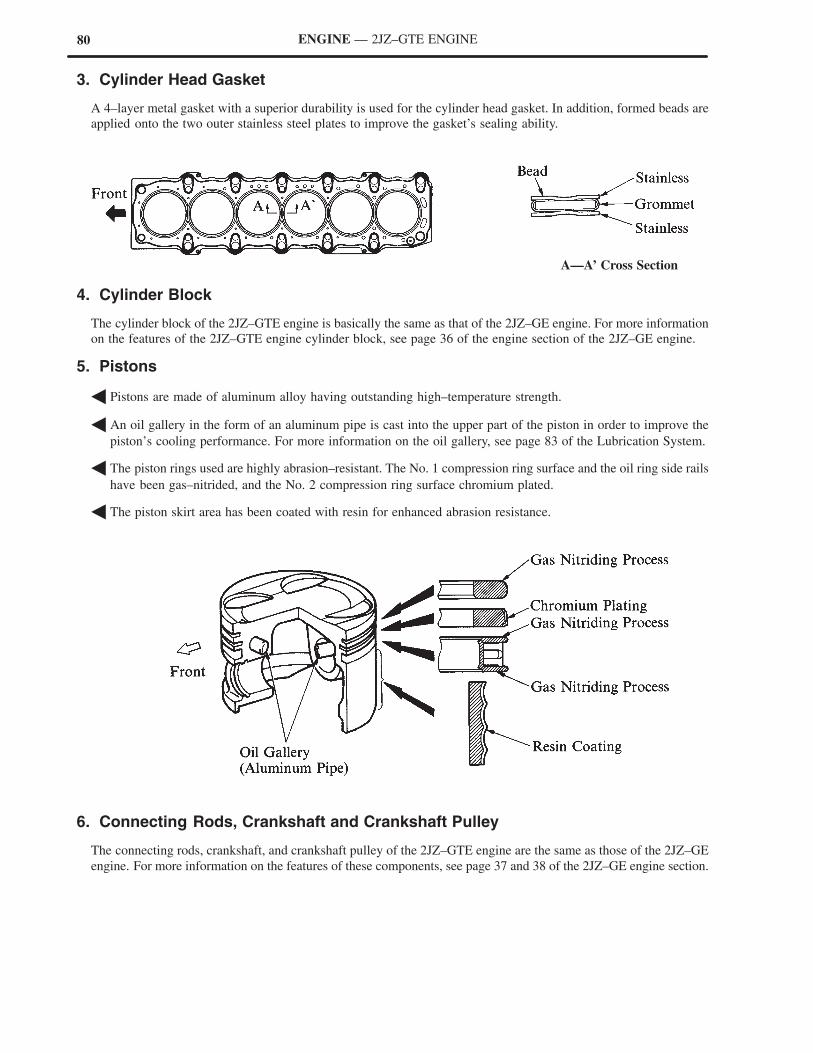
3. Cylinder Head Gasket
A 4–layer metal gasket with a superior durability is used for the cylinder head gasket. In addition, formed beads are
applied onto the two outer stainless steel plates to improve the gasket’s sealing ability.
A—A’ Cross Section
4. Cylinder Block
The cylinder block of the 2JZ–GTE engine is basically the same as that of the 2JZ–GE engine. For more information
on the features of the 2JZ–GTE engine cylinder block, see page 36 of the engine section of the 2JZ–GE engine.
5. Pistons
� Pistons are made of aluminum alloy having outstanding high–temperature strength.
� An oil gallery in the form of an aluminum pipe is cast into the upper part of the piston in order to improve the
piston’s cooling performance. For more information on the oil gallery, see page 83 of the Lubrication System.
� The piston rings used are highly abrasion–resistant. The No. 1 compression ring surface and the oil ring side rails
have been gas–nitrided, and the No. 2 compression ring surface chromium plated.
� The piston skirt area has been coated with resin for enhanced abrasion resistance.
6. Connecting Rods, Crankshaft and Crankshaft Pulley
The connecting rods, crankshaft, and crankshaft pulley of the 2JZ–GTE engine are the same as those of the 2JZ–GE
engine. For more information on the features of these components, see page 37 and 38 of the 2JZ–GE engine section.
81ENGINE — 2JZ–GTE ENGINE
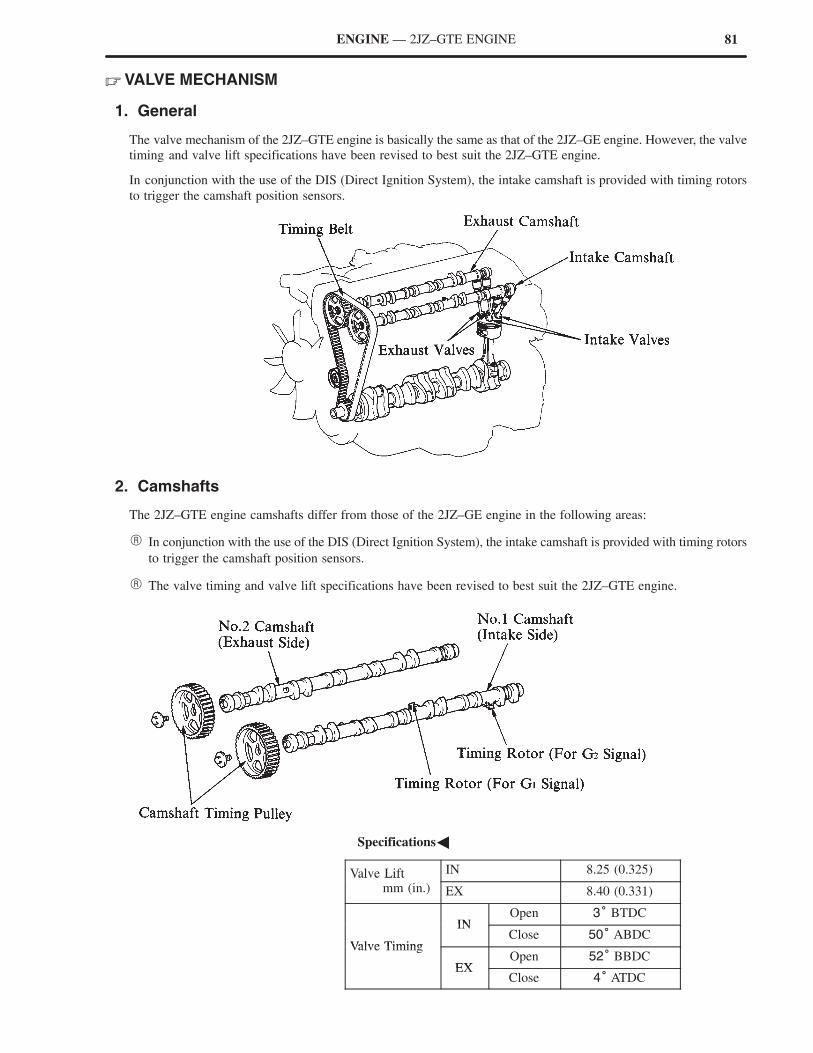
� VALVE MECHANISM
1. General
The valve mechanism of the 2JZ–GTE engine is basically the same as that of the 2JZ–GE engine. However, the valve
timing and valve lift specifications have been revised to best suit the 2JZ–GTE engine.
In conjunction with the use of the DIS (Direct Ignition System), the intake camshaft is provided with timing rotors
to trigger the camshaft position sensors.
2. Camshafts
The 2JZ–GTE engine camshafts differ from those of the 2JZ–GE engine in the following areas:
� In conjunction with the use of the DIS (Direct Ignition System), the intake camshaft is provided with timing rotors
to trigger the camshaft position sensors.
� The valve timing and valve lift specifications have been revised to best suit the 2JZ–GTE engine.
�Specifications�
Valve Lift IN 8.25 (0.325)Valve Liftmm (in.) EX 8.40 (0.331)
INOpen 3° BTDC
Valve Timing
INClose 50° ABDC
Valve Timing
EXOpen 52° BBDC
EXClose 4° ATDC
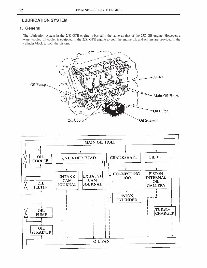
82 ENGINE — 2JZ–GTE ENGINE
� LUBRICATION SYSTEM
1. General
The lubrication system in the 2JZ–GTE engine is basically the same as that of the 2JZ–GE engine. However, a
water–cooled oil cooler is equipped in the 2JZ–GTE engine to cool the engine oil, and oil jets are provided in the
cylinder block to cool the pistons.
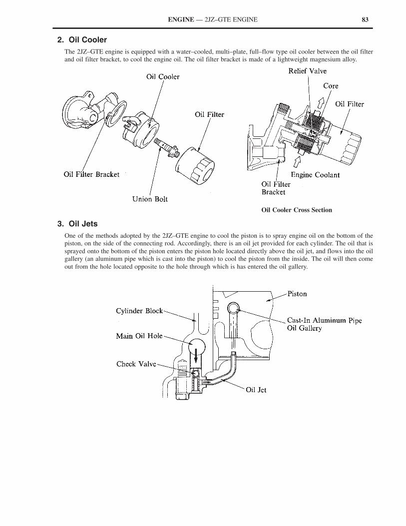
83ENGINE — 2JZ–GTE ENGINE
2. Oil Cooler
The 2JZ–GTE engine is equipped with a water–cooled, multi–plate, full–flow type oil cooler between the oil filter
and oil filter bracket, to cool the engine oil. The oil filter bracket is made of a lightweight magnesium alloy.
Oil Cooler Cross Section
3. Oil Jets
One of the methods adopted by the 2JZ–GTE engine to cool the piston is to spray engine oil on the bottom of the
piston, on the side of the connecting rod. Accordingly, there is an oil jet provided for each cylinder. The oil that is
sprayed onto the bottom of the piston enters the piston hole located directly above the oil jet, and flows into the oil
gallery (an aluminum pipe which is cast into the piston) to cool the piston from the inside. The oil will then come
out from the hole located opposite to the hole through which is has entered the oil gallery.
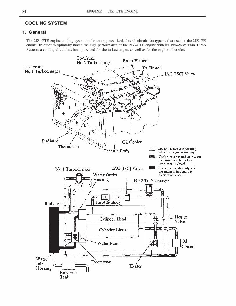
84 ENGINE — 2JZ–GTE ENGINE
� COOLING SYSTEM
1. General
The 2JZ–GTE engine cooling system is the same pressurized, forced–circulation type as that used in the 2JZ–GE
engine. In order to optimally match the high performance of the 2JZ–GTE engine with its Two–Way Twin Turbo
System, a cooling circuit has been provided for the turbochargers as well as for the engine oil cooler.
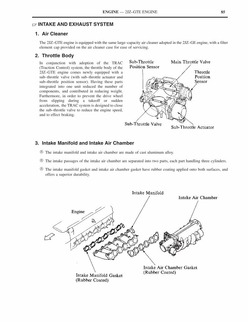
85ENGINE — 2JZ–GTE ENGINE
� INTAKE AND EXHAUST SYSTEM
1. Air Cleaner
The 2JZ–GTE engine is equipped with the same large–capacity air cleaner adopted in the 2JZ–GE engine, with a filter
element cap provided on the air cleaner case for ease of servicing.
2. Throttle Body
In conjunction with adoption of the TRAC
(Traction Control) system, the throttle body of the
2JZ–GTE engine comes newly equipped with a
sub–throttle valve (with sub–throttle actuator and
sub–throttle position sensor). Having these parts
integrated into one unit reduced the number of
components, and contributed in reducing weight.
Furthermore, in order to prevent the drive wheel
from slipping during a takeoff or sudden
acceleration, the TRAC system is designed to close
the sub–throttle valve to reduce the engine speed,
and to effect braking.
3. Intake Manifold and Intake Air Chamber
� The intake manifold and intake air chamber are made of cast aluminum alloy.
� The intake passages of the intake air chamber are separated into two parts, each part handling three cylinders.
� The intake manifold gasket and intake air chamber gasket have rubber coating applied onto both surfaces, and
offers a superior durability.

86 ENGINE — 2JZ–GTE ENGINE
4. Exhaust Manifold
� The exhaust manifolds are made of heat–resistant cast steel with superior heat–resisting and acid–resisting
capacities. The exhaust manifolds are separated into two parts, each part handling three cylinders grouped 1, 2,
3, and 4, 5, 6. The exhaust pressure transmission efficiency is improved in this manner by having each exhaust
manifold direct the exhaust gas flow to each of the turbochargers.
� In conjunction with the adoption of the Two–Way Twin Turbo System, a passage has been provided between the
No. 1 and No. 2 exhaust manifolds. As illustrated below, this passage is of a dual construction consisting of a
stainless–steel connecting pipe and connecting bellows. This construction allows the connecting bellows to
dissipate heat without directly coming into contact with the hot exhaust gas, and minimize the warpage of the
exhaust manifolds due to heat.
� The highly durable 5–layer stainless laminate type gaskets are used for the exhaust manifold gaskets.
� Stainless–plate rings containing filler material are used for the gaskets between the exhaust manifold and the
turbochargers.
�Passage�
A–A’ Cross Section
B–B’ Cross Section
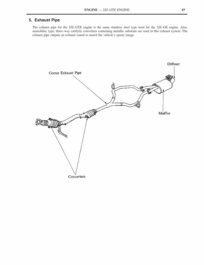
87ENGINE — 2JZ–GTE ENGINE
5. Exhaust Pipe
The exhaust pipe for the 2JZ–GTE engine is the same stainless steel type used for the 2JZ–GE engine. Also,
monolithic type, three–way catalytic converters containing metallic substrate are used in this exhaust system. The
exhaust pipe outputs an exhaust sound to match the vehicle’s sporty image.
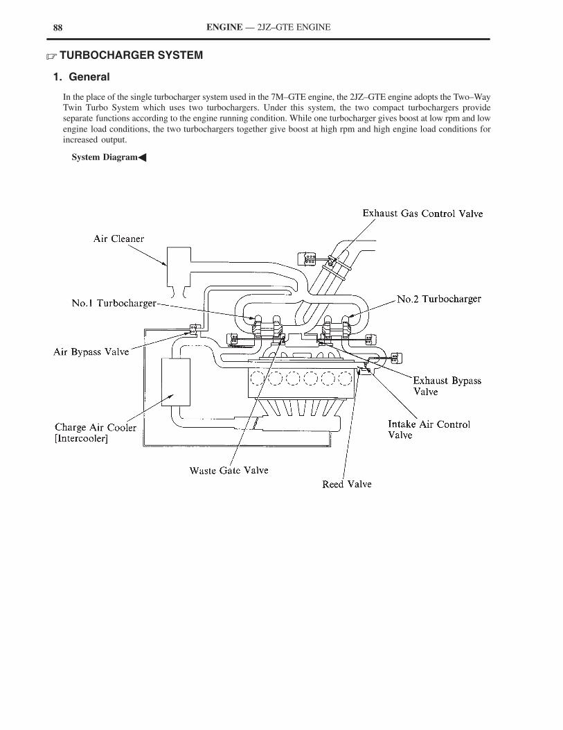
88 ENGINE — 2JZ–GTE ENGINE
� TURBOCHARGER SYSTEM
1. General
In the place of the single turbocharger system used in the 7M–GTE engine, the 2JZ–GTE engine adopts the Two–Way
Twin Turbo System which uses two turbochargers. Under this system, the two compact turbochargers provide
separate functions according to the engine running condition. While one turbocharger gives boost at low rpm and low
engine load conditions, the two turbochargers together give boost at high rpm and high engine load conditions for
increased output.
�System Diagram�
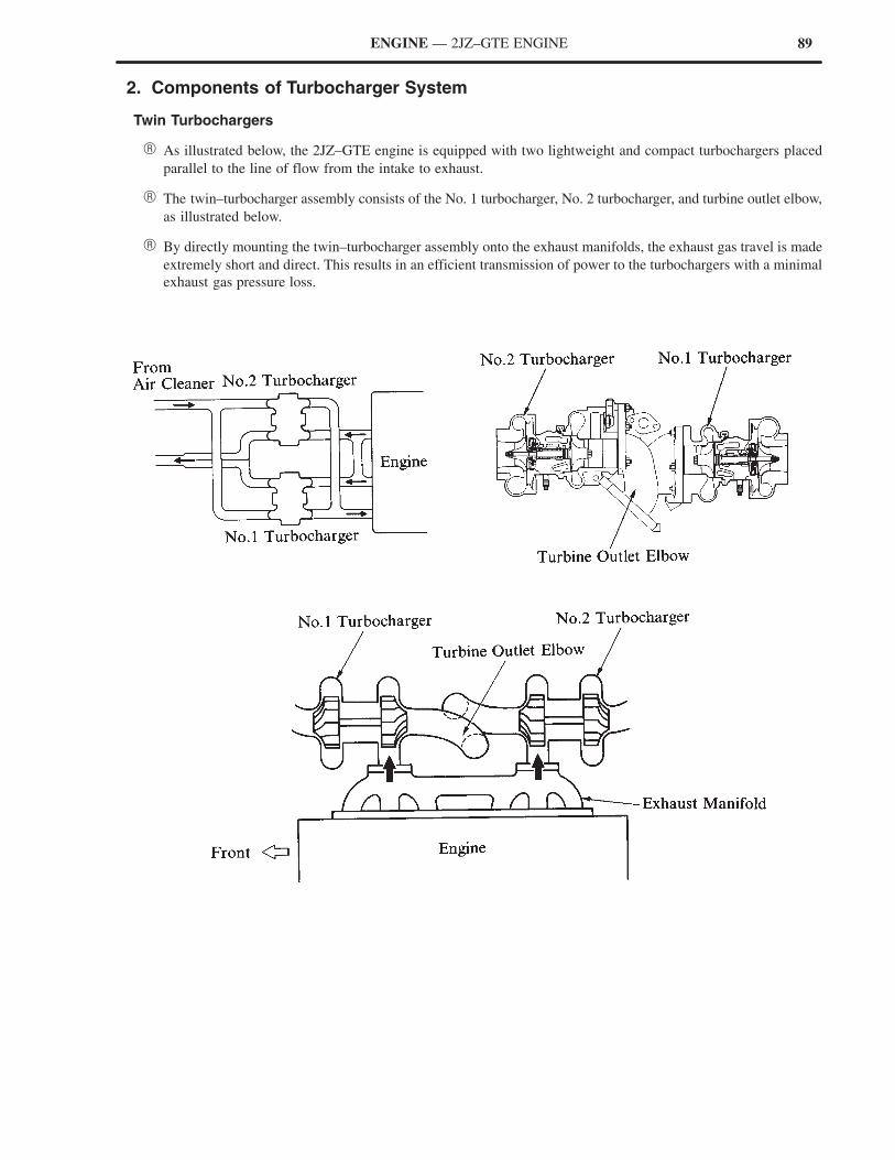
89ENGINE — 2JZ–GTE ENGINE
2. Components of Turbocharger System
Twin Turbochargers
� As illustrated below, the 2JZ–GTE engine is equipped with two lightweight and compact turbochargers placed
parallel to the line of flow from the intake to exhaust.
� The twin–turbocharger assembly consists of the No. 1 turbocharger, No. 2 turbocharger, and turbine outlet elbow,
as illustrated below.
� By directly mounting the twin–turbocharger assembly onto the exhaust manifolds, the exhaust gas travel is made
extremely short and direct. This results in an efficient transmission of power to the turbochargers with a minimal
exhaust gas pressure loss.
90 ENGINE — 2JZ–GTE ENGINE
1) Turbocharger Housing
Each of the turbochargers can be broadly divided in the following three housings: compressor, bearing and
turbine housings.
The compressor housing is made of cast aluminum alloy, and the turbine housing of highly heat–resistant steel.
The bearing housing is made of gray cast steel, in which compact and lightweight impeller and turbine wheels
are enclosed.
No. 1 Turbocharger
a. Bearing housing
The impeller and turbine wheels are enclosed
in the bearing housing via full–floating
bearings. In addition, a coolant passage has
been provided in the housing around the
turbine wheel for improving the cooling
efficiency of its shaft.
i) Turbine Wheel and Impeller Wheel
Both the No. 1 and No. 2 turbochargers features compact and lightweight turbine and impeller wheels. The
turbine wheel is made of metal. The acceleration response of these turbochargers has been improved by making
their shafts and wheels compact and lightweight.
�Specifications� mm (in.)
Engine2JZ GTE 7M GTE
Item2JZ–GTE 7M–GTE
Shaft Diameter D1 7.5 (0.295) 10.0 (0.394)
Impeller
OutletDiameter
D2 58.0 (2.283) 65.0 (2.559)ImpellerWheel Inlet
DiameterD3 39.0 (1.535) 46.0 (1.811)
Turbine
OutletDiameter
D4 44.0 (1.732) 52.0 (2.047)TurbineWheel Inlet
DiameterD5 52.0 (2.047) 68.0 (2.677)
91ENGINE — 2JZ–GTE ENGINE
Charge Air Cooler [Intercooler]
� This turbocharger system adopts an air–cooled, tube type charge air cooler [intercooler] located in the front part
of the right front wheel housing.
� Large–diameter air tubes and hoses are used to accommodate large airflow and reduce its pressure loss.
� The charge air cooler [intercooler] tank and air tubes are made lightweight using plastic.
Charge Air Cooler [Intercooler]
3. Operation of Twin Turbochargers
In this system, the separate functions of the two turbochargers are achieved by controlling the operation of the No.
2 turbocharger. This is accomplished by using control valves to allow or stop the intake air and exhaust gas flow.
Although the No. 2 turbocharger’s basic start/stop operation timing is determined by the engine speed as illustrated
below, the timing is varied according to the engine load.
�No. 2 turbocharger start control� �No. 2 turbocharger stop control�
Region ”A” : low rpm, low engine load
Region ”A” : high rpm, high engine load
TC1 : Only the No. 1 turbocharger operating
TC1 + TC2 : Both the No. 1 and No. 2 turbochargers operating

92 ENGINE — 2JZ–GTE ENGINE
Control Valves
There is a total of six control valves used in the Two–Way Twin Turbo System. The details of these valves are as
follows.
Valve Operation
Intake AirControl Valve
Located downstream of the No. 2 turbocharger intake airflow, during No. 2 turbocharger start/stop operation it permits or stops the flow of intake air through the No. 2 turbocharger.
Exhaust GasControl Valve
Made of ceramic, and located downstream of the No. 2 turbocharger exhaust gas flow, duringNo. 2 turbocharger start/stop operation it permits or stops the flow of exhaust gas through theNo. 2 turbocharger.
Waste GateValve
Integrated into the No. 1 turbocharger, this valve controls the boost pressure of the entire sys-tem by bypassing a portion of the exhaust gas flowing through the No. 1 turbocharger during atwo–turbocharger boost operation.
Exhaust BypassValve
Integrated into the No. 2 turbocharger, this valve controls the boost pressure of the entire sys-tem by bypassing the exhaust gas from the No. 2 turbocharger during a single–turbochargerboost operation (when only the No. 1 turbocharger is boosting). At the same time, this bypassallows the turbine wheel of the No. 2 turbocharger to start spinning ahead of the starting of theNo. 2 turbocharger operation.
Reed Valve
Immediately following the start of the No. 2 turbocharger operation, the intake air controlvalve is closed. This causes a quick rise in the intake air pressure between the No. 2 turbochar-ger and the intake air control valve. The reed valve controls the intake air pressure by bypass-ing a portion of this high–pressure intake air downstream of the reed valve.
Air BypassValve
When the throttle valve is quickly released during boosting, the intake air pressure between theturbocharger and the throttle valve increases rapidly. The air bypass valve diverts a portion ofthis high–pressure intake air upstream of the turbocharger, thereby controlling the boost pres-sure, and reducing the pulsing noise.
93ENGINE — 2JZ–GTE ENGINE
Operation of Single Turbocharging
Since the actuators for the intake air control valve and exhaust gas control valve are inactive during low engine rpm
operation, these valves remain closed.
The waste gate valve is also closed, and only the No. 1 turbocharger will provide the boost pressure. When the intake
air turbocharging pressure downstream from the No. 1 turbocharger reaches a predetermined level, the exhaust bypass
valve executes a boost pressure control. At the same time, the exhaust bypass valve opens to supply the exhaust gas
to the turbine side of the No. 2 turbocharger, causing the No. 2 turbocharger turbine wheel to start rotating.
Accordingly, when the No. 2 turbocharger starts boosting, this process can smooth out the joining of the boost
pressures.
�Valve Condition (Single Turbocharging)�
Intake Air Exhaust GasExhaust Bypass Valve Waste Gate Valve
Intake AirControl Valve
Exhaust GasControl Valve
Exhaust Bypass Valve Waste Gate Valve
Close Close Activated Close
94 ENGINE — 2JZ–GTE ENGINE
Single Turbocharging and Twin Turbocharging Operations
When the engine operation passes from the low–rpm to the high–rpm region, at first the exhaust gas control valve
opens, and this is followed by the opening of the intake air control valve. When the exhaust gas control valve opens,
it causes the No. 2 turbocharger turbine wheel, which had already begun its rotation, to quickly raise its rpm. Thus,
the pressure of the intake air flowing through the No. 2 turbocharger becomes higher than that of the intake air of the
No. 1 turbocharger.
Since this high pressure intake air pushes open the reed valve described below, and flows to the No. 1 turbocharger
side, further rise in pressure is averted.
Then, when the intake air control valve opens, the highly pressurized intake air smoothly joins the intake air coming
from the No. 1 turbocharger (see illustration below).
Conversely, when the engine operation passes from the high–rpm to low–rpm region, in order to stop the No. 2
turbocharger, the valves close in an order opposite to the one described above. The intake air control valve closes first,
followed by the closing of the exhaust gas control valve.
�Valve Condition (Single Turbocharging → Twin Turbocharging)�
Intake Air Exhaust GasExhaust Bypass Valve Waste Gate Valve
Intake AirControl Valve
Exhaust GasControl Valve
Exhaust Bypass Valve Waste Gate Valve
Close → Open Close → Open Activated → Open Close
�Valve Condition (Twin Turbocharging → Single Turbocharging)�
Intake Air Exhaust GasExhaust Bypass Valve Waste Gate Valve
Intake AirControl Valve
Exhaust GasControl Valve
Exhaust Bypass Valve Waste Gate Valve
Open → Close Open → Close Open Activated → Close
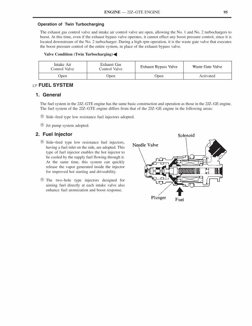
95ENGINE — 2JZ–GTE ENGINE
Operation of Twin Turbocharging
The exhaust gas control valve and intake air control valve are open, allowing the No. 1 and No. 2 turbochargers to
boost. At this time, even if the exhaust bypass valve operates, it cannot effect any boost pressure control, since it is
located downstream of the No. 2 turbocharger. During a high rpm operation, it is the waste gate valve that executes
the boost pressure control of the entire system, in place of the exhaust bypass valve.
�Valve Condition (Twin Turbocharging)�
Intake Air Exhaust GasExhaust Bypass Valve Waste Gate Valve
Intake AirControl Valve
Exhaust GasControl Valve
Exhaust Bypass Valve Waste Gate Valve
Open Open Open Activated
� FUEL SYSTEM
1. General
The fuel system in the 2JZ–GTE engine has the same basic construction and operation as those in the 2JZ–GE engine.
The fuel system of the 2JZ–GTE engine differs from that of the 2JZ–GE engine in the following areas:
� Side–feed type low resistance fuel injectors adopted.
� Jet pump system adopted.
2. Fuel Injector
� Side–feed type low resistance fuel injectors,
having a fuel inlet on the side, are adopted. This
type of fuel injector enables the hot injector to
be cooled by the supply fuel flowing through it.
At the same time, this system can quickly
release the vapor generated inside the injector
for improved hot starting and driveability.
� The two–hole type injectors designed for
aiming fuel directly at each intake valve also
enhance fuel atomization and boost response.
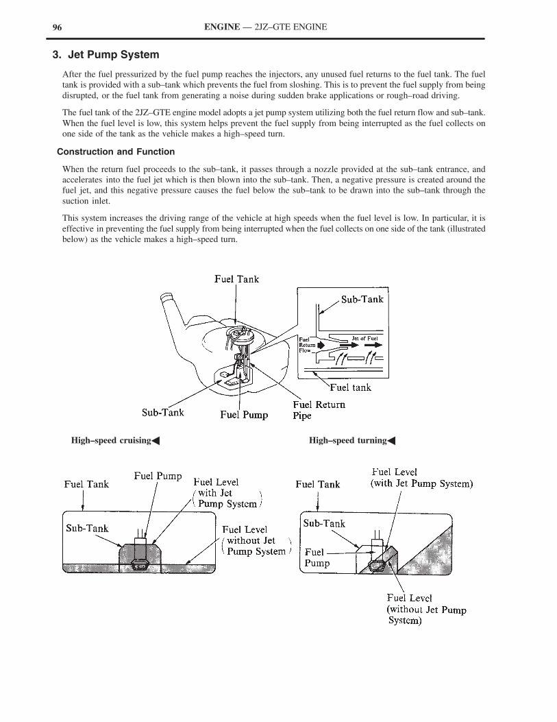
96 ENGINE — 2JZ–GTE ENGINE
3. Jet Pump System
After the fuel pressurized by the fuel pump reaches the injectors, any unused fuel returns to the fuel tank. The fuel
tank is provided with a sub–tank which prevents the fuel from sloshing. This is to prevent the fuel supply from being
disrupted, or the fuel tank from generating a noise during sudden brake applications or rough–road driving.
The fuel tank of the 2JZ–GTE engine model adopts a jet pump system utilizing both the fuel return flow and sub–tank.
When the fuel level is low, this system helps prevent the fuel supply from being interrupted as the fuel collects on
one side of the tank as the vehicle makes a high–speed turn.
Construction and Function
When the return fuel proceeds to the sub–tank, it passes through a nozzle provided at the sub–tank entrance, and
accelerates into the fuel jet which is then blown into the sub–tank. Then, a negative pressure is created around the
fuel jet, and this negative pressure causes the fuel below the sub–tank to be drawn into the sub–tank through the
suction inlet.
This system increases the driving range of the vehicle at high speeds when the fuel level is low. In particular, it is
effective in preventing the fuel supply from being interrupted when the fuel collects on one side of the tank (illustrated
below) as the vehicle makes a high–speed turn.
�High–speed cruising� �High–speed turning�
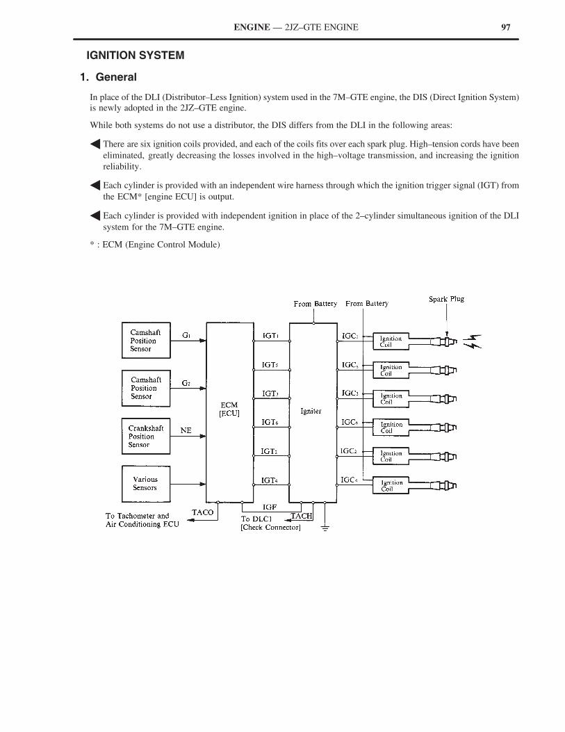
97ENGINE — 2JZ–GTE ENGINE
� IGNITION SYSTEM
1. General
In place of the DLI (Distributor–Less Ignition) system used in the 7M–GTE engine, the DIS (Direct Ignition System)
is newly adopted in the 2JZ–GTE engine.
While both systems do not use a distributor, the DIS differs from the DLI in the following areas:
� There are six ignition coils provided, and each of the coils fits over each spark plug. High–tension cords have been
eliminated, greatly decreasing the losses involved in the high–voltage transmission, and increasing the ignition
reliability.
� Each cylinder is provided with an independent wire harness through which the ignition trigger signal (IGT) from
the ECM* [engine ECU] is output.
� Each cylinder is provided with independent ignition in place of the 2–cylinder simultaneous ignition of the DLI
system for the 7M–GTE engine.
* : ECM (Engine Control Module)
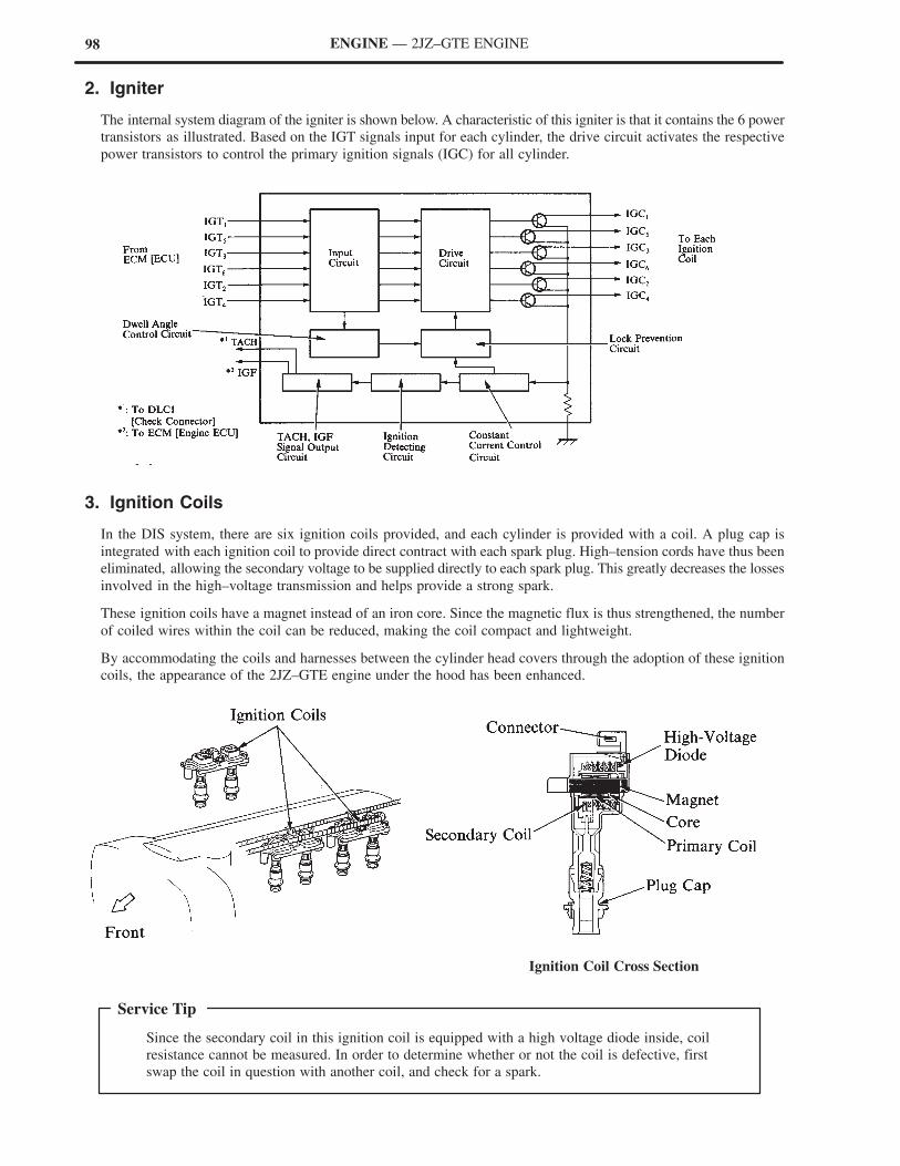
98
Since the secondary coil in this ignition coil is equipped with a high voltage diode inside, coil
resistance cannot be measured. In order to determine whether or not the coil is defective, first
swap the coil in question with another coil, and check for a spark.
Service Tip
ENGINE — 2JZ–GTE ENGINE
2. Igniter
The internal system diagram of the igniter is shown below. A characteristic of this igniter is that it contains the 6 power
transistors as illustrated. Based on the IGT signals input for each cylinder, the drive circuit activates the respective
power transistors to control the primary ignition signals (IGC) for all cylinder.
3. Ignition Coils
In the DIS system, there are six ignition coils provided, and each cylinder is provided with a coil. A plug cap is
integrated with each ignition coil to provide direct contract with each spark plug. High–tension cords have thus been
eliminated, allowing the secondary voltage to be supplied directly to each spark plug. This greatly decreases the losses
involved in the high–voltage transmission and helps provide a strong spark.
These ignition coils have a magnet instead of an iron core. Since the magnetic flux is thus strengthened, the number
of coiled wires within the coil can be reduced, making the coil compact and lightweight.
By accommodating the coils and harnesses between the cylinder head covers through the adoption of these ignition
coils, the appearance of the 2JZ–GTE engine under the hood has been enhanced.
Ignition Coil Cross Section
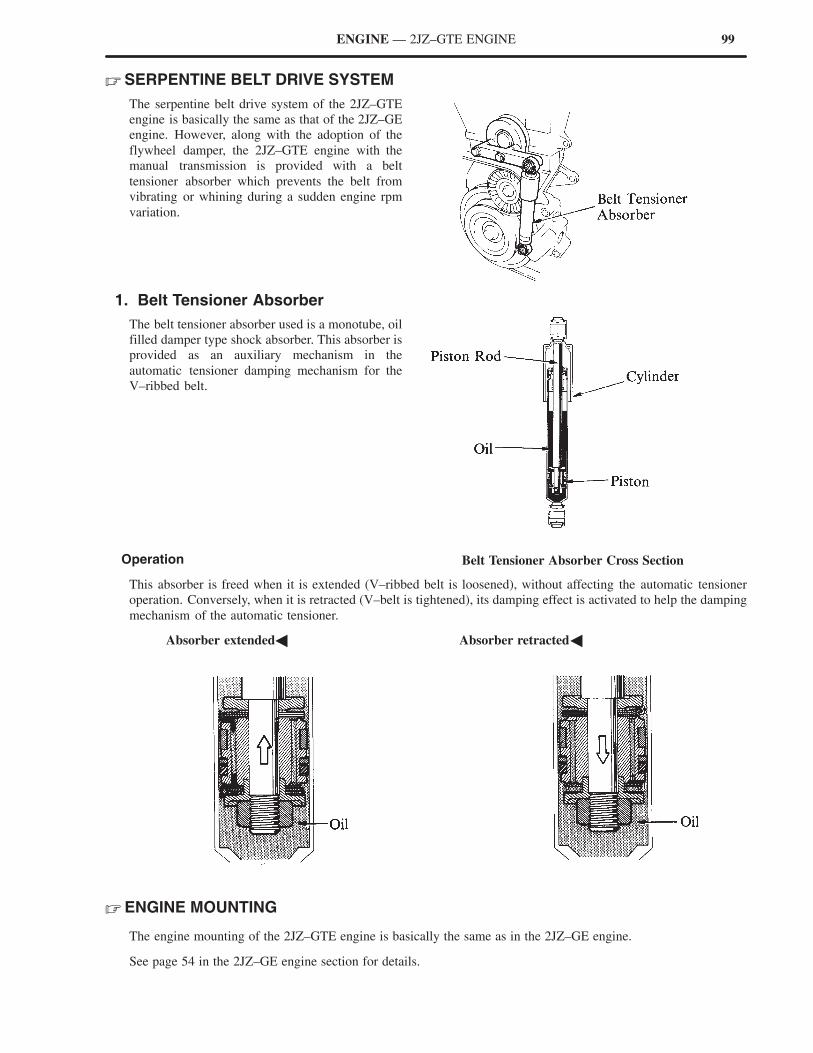
99
Belt Tensioner Absorber Cross Section
ENGINE — 2JZ–GTE ENGINE
� SERPENTINE BELT DRIVE SYSTEM
The serpentine belt drive system of the 2JZ–GTE
engine is basically the same as that of the 2JZ–GE
engine. However, along with the adoption of the
flywheel damper, the 2JZ–GTE engine with the
manual transmission is provided with a belt
tensioner absorber which prevents the belt from
vibrating or whining during a sudden engine rpm
variation.
1. Belt Tensioner Absorber
The belt tensioner absorber used is a monotube, oil
filled damper type shock absorber. This absorber is
provided as an auxiliary mechanism in the
automatic tensioner damping mechanism for the
V–ribbed belt.
Operation
This absorber is freed when it is extended (V–ribbed belt is loosened), without affecting the automatic tensioner
operation. Conversely, when it is retracted (V–belt is tightened), its damping effect is activated to help the damping
mechanism of the automatic tensioner.
�Absorber extended� �Absorber retracted�
� ENGINE MOUNTING
The engine mounting of the 2JZ–GTE engine is basically the same as in the 2JZ–GE engine.
See page 54 in the 2JZ–GE engine section for details.
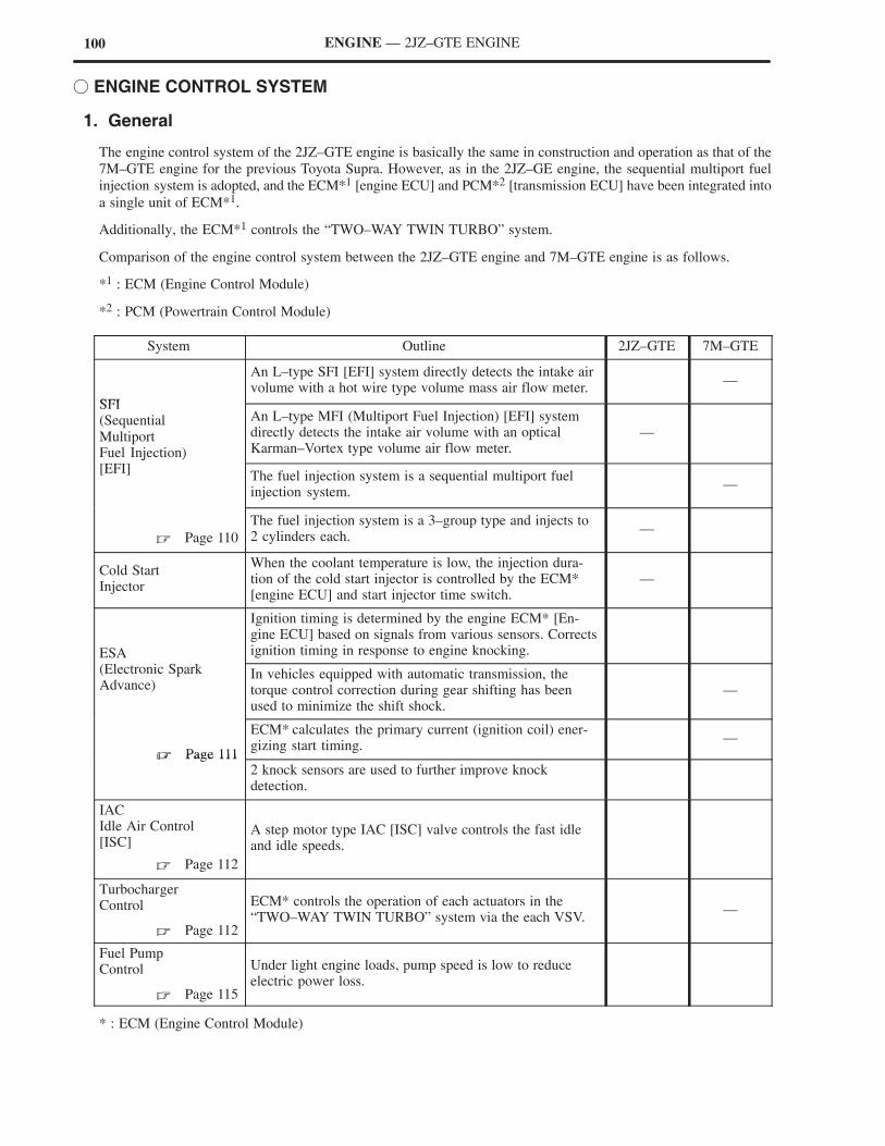
100 ENGINE — 2JZ–GTE ENGINE
� ENGINE CONTROL SYSTEM
1. General
The engine control system of the 2JZ–GTE engine is basically the same in construction and operation as that of the
7M–GTE engine for the previous Toyota Supra. However, as in the 2JZ–GE engine, the sequential multiport fuel
injection system is adopted, and the ECM*1 [engine ECU] and PCM*2 [transmission ECU] have been integrated into
a single unit of ECM*1.
Additionally, the ECM*1 controls the “TWO–WAY TWIN TURBO” system.
Comparison of the engine control system between the 2JZ–GTE engine and 7M–GTE engine is as follows.
*1 : ECM (Engine Control Module)
*2 : PCM (Powertrain Control Module)
System Outline 2JZ–GTE 7M–GTE
SFI
An L–type SFI [EFI] system directly detects the intake airvolume with a hot wire type volume mass air flow meter.
—
SFI(SequentialMultiportFuel Injection)
An L–type MFI (Multiport Fuel Injection) [EFI] systemdirectly detects the intake air volume with an optical Karman–Vortex type volume air flow meter.
—
j )[EFI]
The fuel injection system is a sequential multiport fuelinjection system.
—
� Page 110
The fuel injection system is a 3–group type and injects to2 cylinders each.
—
Cold StartInjector
When the coolant temperature is low, the injection dura-tion of the cold start injector is controlled by the ECM*[engine ECU] and start injector time switch.
—
ESA
Ignition timing is determined by the engine ECM* [En-gine ECU] based on signals from various sensors. Correctsignition timing in response to engine knocking.
(Electronic Spark Advance)
In vehicles equipped with automatic transmission, thetorque control correction during gear shifting has beenused to minimize the shift shock.
—
� Page 111
ECM* calculates the primary current (ignition coil) ener-gizing start timing.
—� Page 111
2 knock sensors are used to further improve knock detection.
IACIdle Air Control[ISC]
� Page 112
A step motor type IAC [ISC] valve controls the fast idleand idle speeds.
TurbochargerControl
� Page 112
ECM* controls the operation of each actuators in the“TWO–WAY TWIN TURBO” system via the each VSV.
—
Fuel PumpControl
� Page 115
Under light engine loads, pump speed is low to reduceelectric power loss.
* : ECM (Engine Control Module)
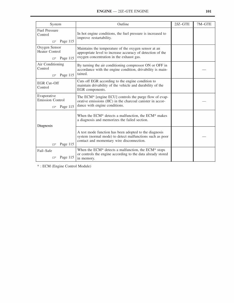
101ENGINE — 2JZ–GTE ENGINE
System Outline 2JZ–GTE 7M–GTE
Fuel PressureControl
� Page 115
In hot engine conditions, the fuel pressure is increased toimprove restartability.
Oxygen SensorHeater Control
� Page 115
Maintains the temperature of the oxygen sensor at anappropriate level to increase accuracy of detection of theoxygen concentration in the exhaust gas.
Air ConditioningControl
� Page 115
By turning the air conditioning compressor ON or OFF inaccordance with the engine condition, drivability is main-tained.
—
EGR Cut–OffControl
Cuts off EGR according to the engine condition tomaintain drivability of the vehicle and durability of theEGR components.
EvaporativeEmission Control
� Page 115
The ECM* [engine ECU] controls the purge flow of evap-orative emissions (HC) in the charcoal canister in accor-dance with engine conditions.
—
Diagnosis
When the ECM* detects a malfunction, the ECM* makesa diagnosis and memorizes the failed section.
Diagnosis
� Page 115
A test mode function has been adopted to the diagnosissystem (normal mode) to detect malfunctions such as poorcontact and momentary wire disconnection.
—
Fail–Safe
� Page 115
When the ECM* detects a malfunction, the ECM* stopsor controls the engine according to the data already storedin memory.
* : ECM (Engine Control Module)
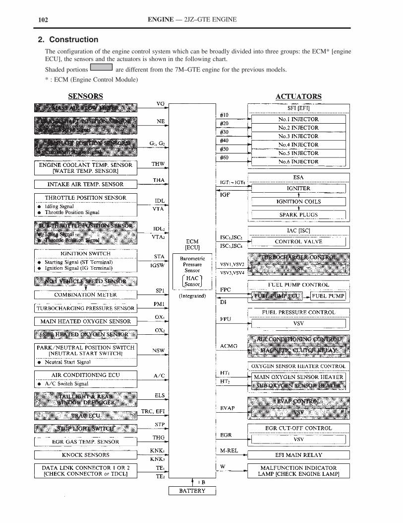
102 ENGINE — 2JZ–GTE ENGINE
2. Construction
The configuration of the engine control system which can be broadly divided into three groups: the ECM* [engine
ECU], the sensors and the actuators is shown in the following chart.
Shaded portions are different from the 7M–GTE engine for the previous models.
* : ECM (Engine Control Module)
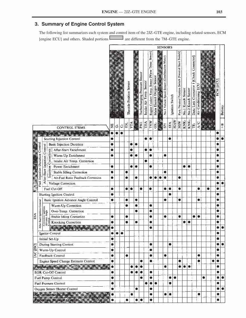
103ENGINE — 2JZ–GTE ENGINE
3. Summary of Engine Control System
The following list summarizes each system and control item of the 2JZ–GTE engine, including related sensors, ECM
[engine ECU] and others. Shaded portions are different from the 7M–GTE engine.
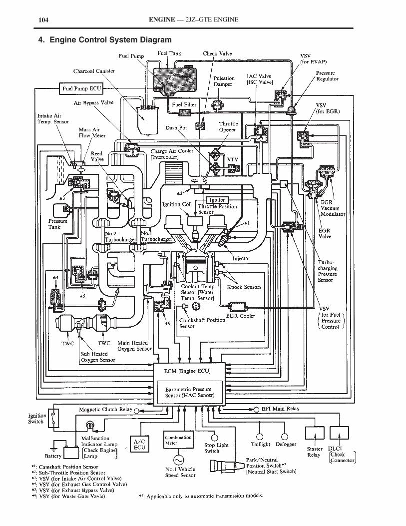
104 ENGINE — 2JZ–GTE ENGINE
4. Engine Control System Diagram
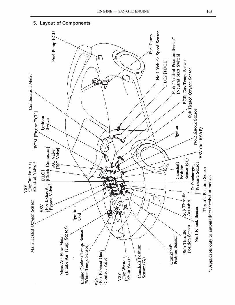
105ENGINE — 2JZ–GTE ENGINE
5. Layout of Components
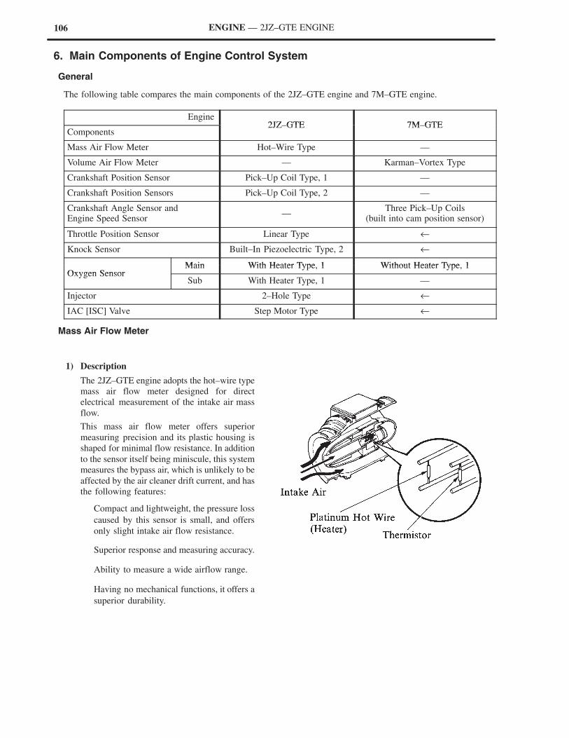
106 ENGINE — 2JZ–GTE ENGINE
6. Main Components of Engine Control System
General
The following table compares the main components of the 2JZ–GTE engine and 7M–GTE engine.
Engine2JZ GTE 7M GTE
Components2JZ–GTE 7M–GTE
Mass Air Flow Meter Hot–Wire Type —
Volume Air Flow Meter — Karman–Vortex Type
Crankshaft Position Sensor Pick–Up Coil Type, 1 —
Crankshaft Position Sensors Pick–Up Coil Type, 2 —
Crankshaft Angle Sensor andEngine Speed Sensor
—Three Pick–Up Coils
(built into cam position sensor)
Throttle Position Sensor Linear Type ←
Knock Sensor Built–In Piezoelectric Type, 2 ←
Main With Heater Type 1 Without Heater Type 1Oxygen Sensor
Main With Heater Type, 1 Without Heater Type, 1Oxygen Sensor
Sub With Heater Type, 1 —
Injector 2–Hole Type ←
IAC [ISC] Valve Step Motor Type ←
Mass Air Flow Meter
1) Description
The 2JZ–GTE engine adopts the hot–wire type
mass air flow meter designed for direct
electrical measurement of the intake air mass
flow.
This mass air flow meter offers superior
measuring precision and its plastic housing is
shaped for minimal flow resistance. In addition
to the sensor itself being miniscule, this system
measures the bypass air, which is unlikely to be
affected by the air cleaner drift current, and has
the following features:
Compact and lightweight, the pressure loss
caused by this sensor is small, and offers
only slight intake air flow resistance.
Superior response and measuring accuracy.
Ability to measure a wide airflow range.
Having no mechanical functions, it offers a
superior durability.
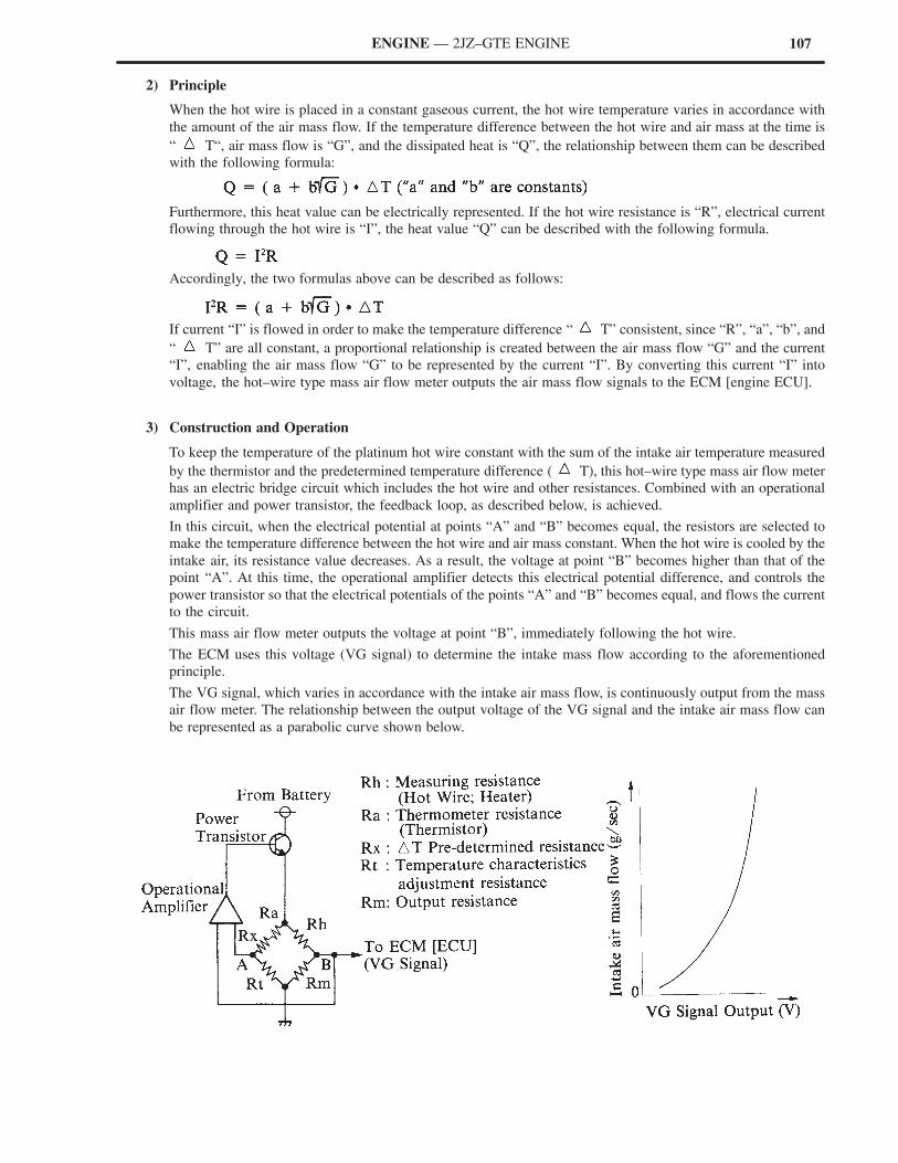
107ENGINE — 2JZ–GTE ENGINE
2) Principle
When the hot wire is placed in a constant gaseous current, the hot wire temperature varies in accordance with
the amount of the air mass flow. If the temperature difference between the hot wire and air mass at the time is
“ T“, air mass flow is “G”, and the dissipated heat is “Q”, the relationship between them can be described
with the following formula:
Furthermore, this heat value can be electrically represented. If the hot wire resistance is “R”, electrical current
flowing through the hot wire is “I”, the heat value “Q” can be described with the following formula.
Accordingly, the two formulas above can be described as follows:
If current “I” is flowed in order to make the temperature difference “ T” consistent, since “R”, “a”, “b”, and
“ T” are all constant, a proportional relationship is created between the air mass flow “G” and the current
“I”, enabling the air mass flow “G” to be represented by the current “I”. By converting this current “I” into
voltage, the hot–wire type mass air flow meter outputs the air mass flow signals to the ECM [engine ECU].
3) Construction and Operation
To keep the temperature of the platinum hot wire constant with the sum of the intake air temperature measured
by the thermistor and the predetermined temperature difference ( T), this hot–wire type mass air flow meter
has an electric bridge circuit which includes the hot wire and other resistances. Combined with an operational
amplifier and power transistor, the feedback loop, as described below, is achieved.
In this circuit, when the electrical potential at points “A” and “B” becomes equal, the resistors are selected to
make the temperature difference between the hot wire and air mass constant. When the hot wire is cooled by the
intake air, its resistance value decreases. As a result, the voltage at point “B” becomes higher than that of the
point “A”. At this time, the operational amplifier detects this electrical potential difference, and controls the
power transistor so that the electrical potentials of the points “A” and “B” becomes equal, and flows the current
to the circuit.
This mass air flow meter outputs the voltage at point “B”, immediately following the hot wire.
The ECM uses this voltage (VG signal) to determine the intake mass flow according to the aforementioned
principle.
The VG signal, which varies in accordance with the intake air mass flow, is continuously output from the mass
air flow meter. The relationship between the output voltage of the VG signal and the intake air mass flow can
be represented as a parabolic curve shown below.
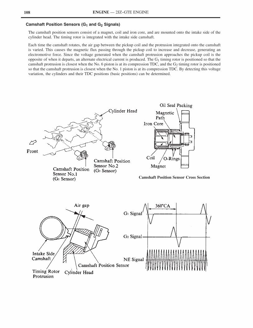
108 ENGINE — 2JZ–GTE ENGINE
Camshaft Position Sensors (G1 and G2 Signals)
The camshaft position sensors consist of a magnet, coil and iron core, and are mounted onto the intake side of the
cylinder head. The timing rotor is integrated with the intake side camshaft.
Each time the camshaft rotates, the air gap between the pickup coil and the protrusion integrated onto the camshaft
is varied. This causes the magnetic flux passing through the pickup coil to increase and decrease, generating an
electromotive force. Since the voltage generated when the camshaft protrusion approaches the pickup coil is the
opposite of when it departs, an alternate electrical current is produced. The G1 timing rotor is positioned so that the
camshaft protrusion is closest when the No. 6 piston is at its compression TDC, and the G2 timing rotor is positioned
so that the camshaft protrusion is closest when the No. 1 piston is at its compression TDC. By detecting this voltage
variation, the cylinders and their TDC positions (basic positions) can be determined.
Camshaft Position Sensor Cross Section
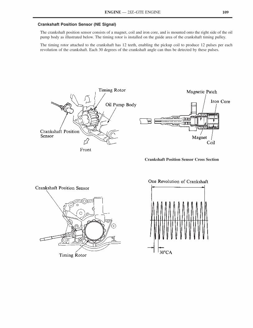
109ENGINE — 2JZ–GTE ENGINE
Crankshaft Position Sensor (NE Signal)
The crankshaft position sensor consists of a magnet, coil and iron core, and is mounted onto the right side of the oil
pump body as illustrated below. The timing rotor is installed on the guide area of the crankshaft timing pulley.
The timing rotor attached to the crankshaft has 12 teeth, enabling the pickup coil to produce 12 pulses per each
revolution of the crankshaft. Each 30 degrees of the crankshaft angle can thus be detected by these pulses.
Crankshaft Position Sensor Cross Section
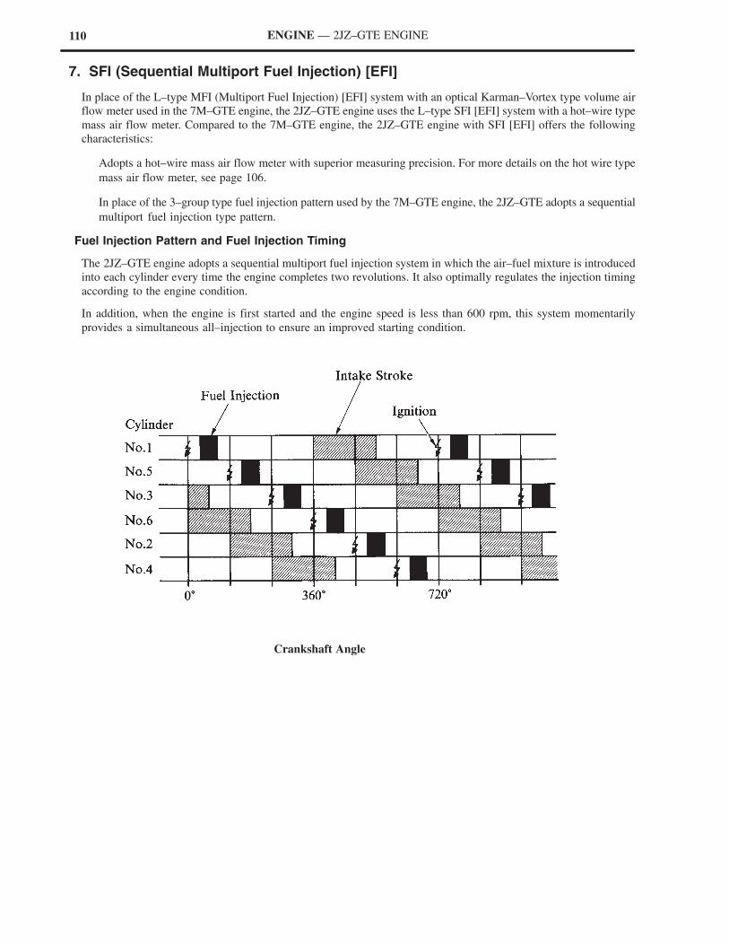
110 ENGINE — 2JZ–GTE ENGINE
7. SFI (Sequential Multiport Fuel Injection) [EFI]
In place of the L–type MFI (Multiport Fuel Injection) [EFI] system with an optical Karman–Vortex type volume air
flow meter used in the 7M–GTE engine, the 2JZ–GTE engine uses the L–type SFI [EFI] system with a hot–wire type
mass air flow meter. Compared to the 7M–GTE engine, the 2JZ–GTE engine with SFI [EFI] offers the following
characteristics:
Adopts a hot–wire mass air flow meter with superior measuring precision. For more details on the hot wire type
mass air flow meter, see page 106.
In place of the 3–group type fuel injection pattern used by the 7M–GTE engine, the 2JZ–GTE adopts a sequential
multiport fuel injection type pattern.
Fuel Injection Pattern and Fuel Injection Timing
The 2JZ–GTE engine adopts a sequential multiport fuel injection system in which the air–fuel mixture is introduced
into each cylinder every time the engine completes two revolutions. It also optimally regulates the injection timing
according to the engine condition.
In addition, when the engine is first started and the engine speed is less than 600 rpm, this system momentarily
provides a simultaneous all–injection to ensure an improved starting condition.
Crankshaft Angle
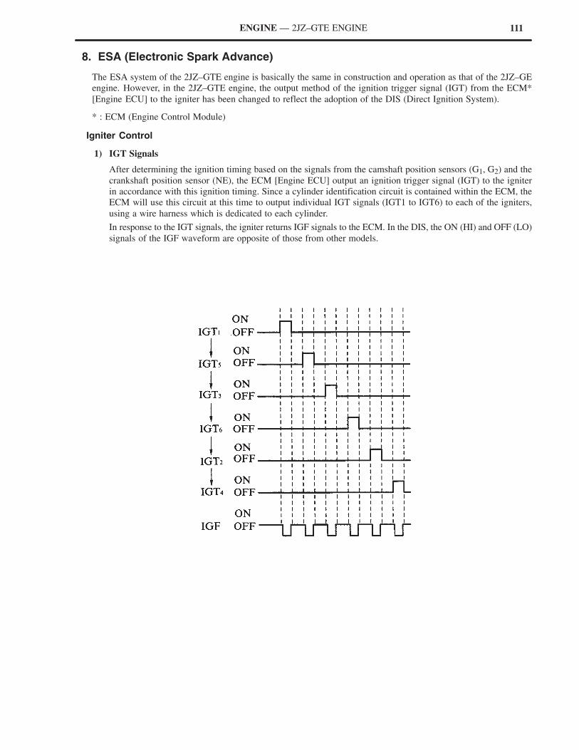
111ENGINE — 2JZ–GTE ENGINE
8. ESA (Electronic Spark Advance)
The ESA system of the 2JZ–GTE engine is basically the same in construction and operation as that of the 2JZ–GE
engine. However, in the 2JZ–GTE engine, the output method of the ignition trigger signal (IGT) from the ECM*
[Engine ECU] to the igniter has been changed to reflect the adoption of the DIS (Direct Ignition System).
* : ECM (Engine Control Module)
Igniter Control
1) IGT Signals
After determining the ignition timing based on the signals from the camshaft position sensors (G1, G2) and the
crankshaft position sensor (NE), the ECM [Engine ECU] output an ignition trigger signal (IGT) to the igniter
in accordance with this ignition timing. Since a cylinder identification circuit is contained within the ECM, the
ECM will use this circuit at this time to output individual IGT signals (IGT1 to IGT6) to each of the igniters,
using a wire harness which is dedicated to each cylinder.
In response to the IGT signals, the igniter returns IGF signals to the ECM. In the DIS, the ON (HI) and OFF (LO)
signals of the IGF waveform are opposite of those from other models.
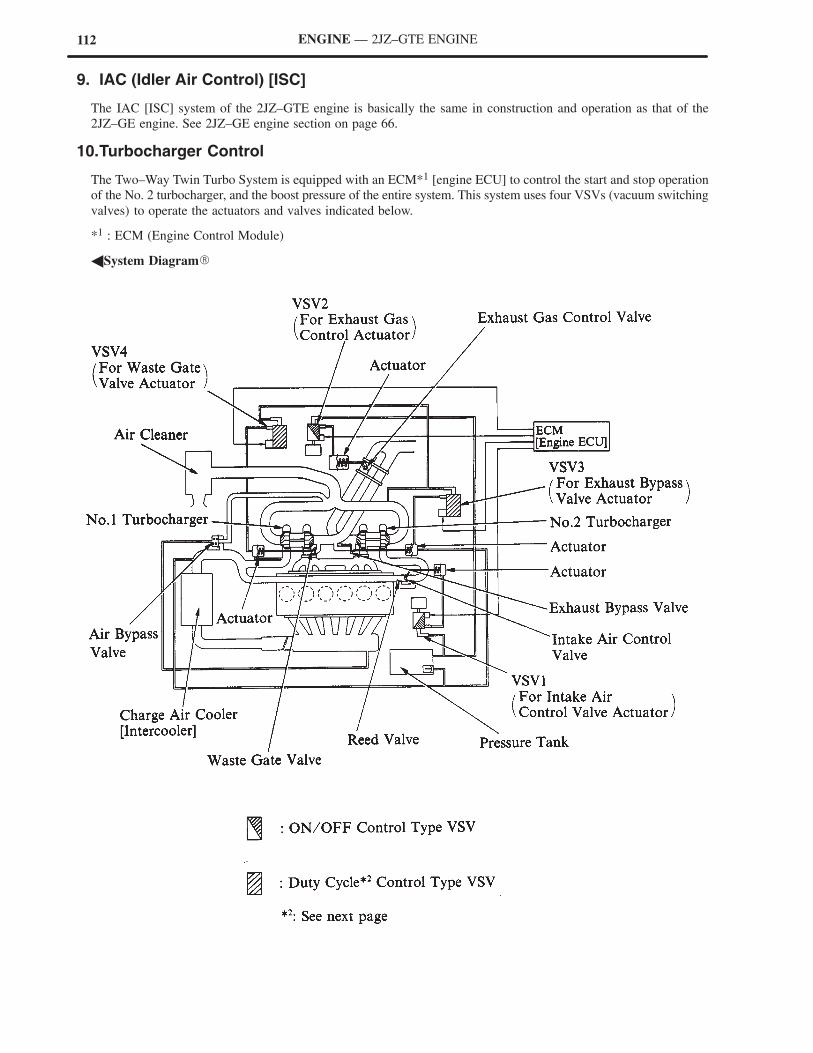
112 ENGINE — 2JZ–GTE ENGINE
9. IAC (Idler Air Control) [ISC]
The IAC [ISC] system of the 2JZ–GTE engine is basically the same in construction and operation as that of the
2JZ–GE engine. See 2JZ–GE engine section on page 66.
10.Turbocharger Control
The Two–Way Twin Turbo System is equipped with an ECM*1 [engine ECU] to control the start and stop operation
of the No. 2 turbocharger, and the boost pressure of the entire system. This system uses four VSVs (vacuum switching
valves) to operate the actuators and valves indicated below.
*1 : ECM (Engine Control Module)
�System Diagram�
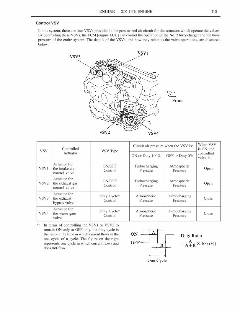
113ENGINE — 2JZ–GTE ENGINE
Control VSV
In this system, there are four VSVs provided in the pressurized air circuit for the actuators which operate the valves.
By controlling these VSVs, the ECM [engine ECU] can control the operation of the No. 2 turbocharger and the boost
pressure of the entire system. The details of the VSVs, and how they relate to the valve operations, are discussed
below.
VSVControlled
VSV Type
Circuit air pressure when the VSV is: When VSVis ON, the
VSVControlledActuator
VSV Type
ON or Duty 100% OFF or Duty 0%
is ON, thecontrolledvalve is:
VSV1Actuator forthe intake air
ON/OFF Turbocharging AtmosphericOpenVSV1 the intake air
control valve
ON/OFFControl
TurbochargingPressure
AtmosphericPressure
Open
VSV2Actuator forthe exhaust gascontrol valve
ON/OFFControl
TurbochargingPressure
AtmosphericPressure
Open
VSV3Actuator forthe exhaustbypass valve
Duty Cycle*Control
AtmosphericPressure
TurbochargingPressure
Close
VSV4Actuator forthe waste gatevalve
Duty Cycle*Control
AtmosphericPressure
TurbochargingPressure
Close
*: In terms of controlling the VSV1 or VSV2 to
remain ON only or OFF only, the duty cycle is
the ratio of the time in which current flows in the
one cycle of a cycle. The figure on the right
represents one cycle in which current flows and
does not flow.
114
Engine speed (NE)
Throttle position (VTA)
Ignition switch (IGSW)
Intake air volume (VG)
Intake air temperature (THA)
Park/neutral position switch
[Neutral start switch] (NSW)
Vehicle speed (SP1)
RELEVANT SIGNALS
Throttle position (VTA)
Vehicle speed (SP1)
Engine speed (NE)
RELEVANT SIGNALS
Turbocharging pressure sensor (PM1)
Park/neutral position switch
[Neutral start switch] (NSW)
Throttle position (VTA)
Intake air volume (VG)
RELEVANT SIGNALS
Turbocharging pressure sensor (PM1)
Park/neutral position switch
[Neutral start switch] (NSW)
Throttle position (VTA)
Engine speed (NE)
RELEVANT SIGNALS
ENGINE — 2JZ–GTE ENGINE
ECM [ECU] Function
1) Exhaust Gas Control Valve Control
When the engine is accelerated from a speed of
approximately 3,000 to 4,000 rpm, the ECM
[ECU] turns the VSV2 ON to open the exhaust
gas control valve, in accordance with the
degree of the acceleration. This causes the
turbine wheel revolution to go suddenly from
a freewheeling state to high rpm.
2) Intake Air Control Valve Control
When the exhaust gas control valve remains
open longer than a predetermined time, the
ECM turns ON VSV1 to open the intake air
control valve. This causes the No. 2
turbocharger to provide a full boost, effecting
a twin turbocharging operation.
3) Exhaust Bypass Valve Control
When the exhaust gas control valve is closed
(only the No. 1 turbocharger is providing
boost), and the intake air boost pressure
exceeds a predetermined value, the ECM
applies a feedback control of the exhaust
bypass valve via VSV3. In addition to
providing the boost pressure control for the
entire system, this feedback control also
enables the No. 2 turbocharger turbine wheel to
freewheel.
4) Waste Gate Valve Control
When only the No. 1 turbocharger is applying
the boost pressure, the ECM maintains the
waste gate valve closed.
When the two turbochargers are boosting, the
ECM applies a feedback control of the waste
gate valve via VSV4 to control the boost
pressure of the entire system. In case of a
failure of the turbocharging pressure sensor, the
ECM fixes the duty cycle to 0% so that the
valve can be operated by the intake air boost
pressure.
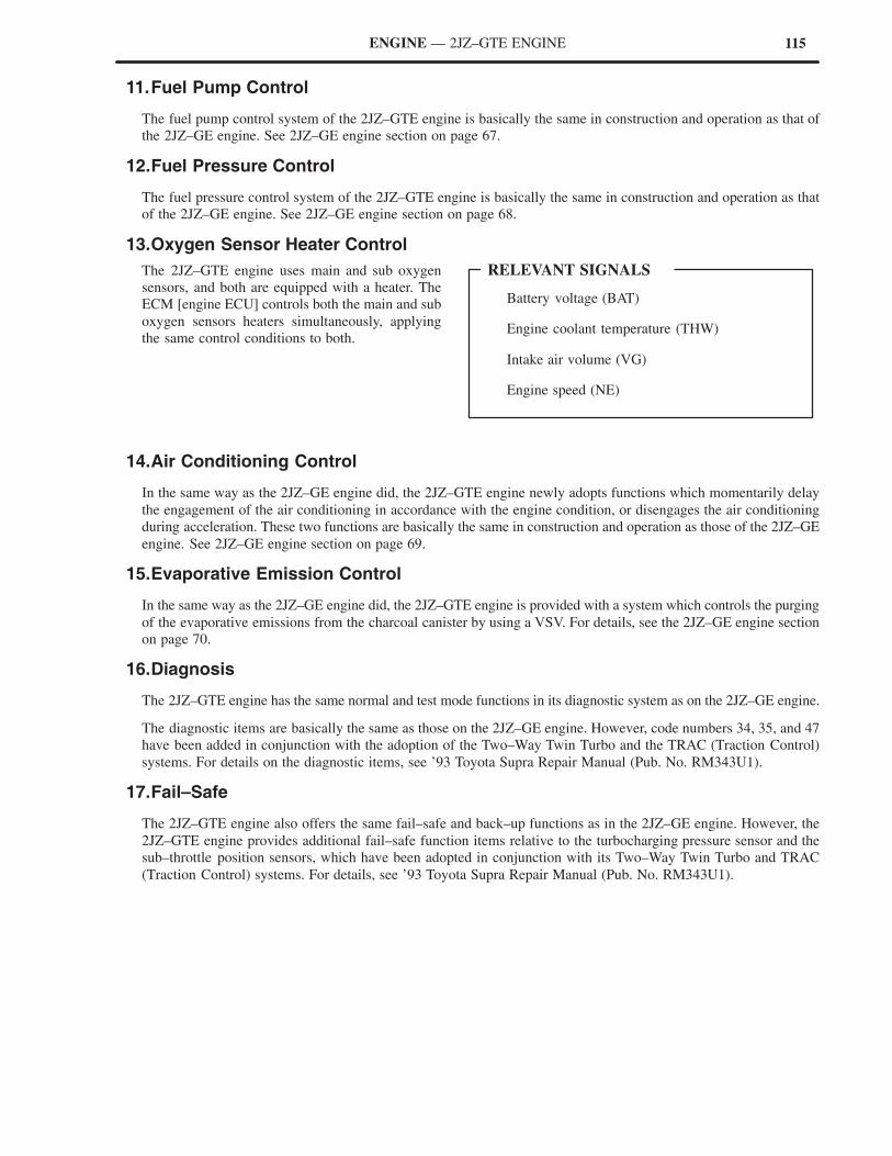
115
Battery voltage (BAT)
Engine coolant temperature (THW)
Intake air volume (VG)
Engine speed (NE)
RELEVANT SIGNALS
ENGINE — 2JZ–GTE ENGINE
11.Fuel Pump Control
The fuel pump control system of the 2JZ–GTE engine is basically the same in construction and operation as that of
the 2JZ–GE engine. See 2JZ–GE engine section on page 67.
12.Fuel Pressure Control
The fuel pressure control system of the 2JZ–GTE engine is basically the same in construction and operation as that
of the 2JZ–GE engine. See 2JZ–GE engine section on page 68.
13.Oxygen Sensor Heater Control
The 2JZ–GTE engine uses main and sub oxygen
sensors, and both are equipped with a heater. The
ECM [engine ECU] controls both the main and sub
oxygen sensors heaters simultaneously, applying
the same control conditions to both.
14.Air Conditioning Control
In the same way as the 2JZ–GE engine did, the 2JZ–GTE engine newly adopts functions which momentarily delay
the engagement of the air conditioning in accordance with the engine condition, or disengages the air conditioning
during acceleration. These two functions are basically the same in construction and operation as those of the 2JZ–GE
engine. See 2JZ–GE engine section on page 69.
15.Evaporative Emission Control
In the same way as the 2JZ–GE engine did, the 2JZ–GTE engine is provided with a system which controls the purging
of the evaporative emissions from the charcoal canister by using a VSV. For details, see the 2JZ–GE engine section
on page 70.
16.Diagnosis
The 2JZ–GTE engine has the same normal and test mode functions in its diagnostic system as on the 2JZ–GE engine.
The diagnostic items are basically the same as those on the 2JZ–GE engine. However, code numbers 34, 35, and 47
have been added in conjunction with the adoption of the Two–Way Twin Turbo and the TRAC (Traction Control)
systems. For details on the diagnostic items, see ’93 Toyota Supra Repair Manual (Pub. No. RM343U1).
17.Fail–Safe
The 2JZ–GTE engine also offers the same fail–safe and back–up functions as in the 2JZ–GE engine. However, the
2JZ–GTE engine provides additional fail–safe function items relative to the turbocharging pressure sensor and the
sub–throttle position sensors, which have been adopted in conjunction with its Two–Way Twin Turbo and TRAC
(Traction Control) systems. For details, see ’93 Toyota Supra Repair Manual (Pub. No. RM343U1).
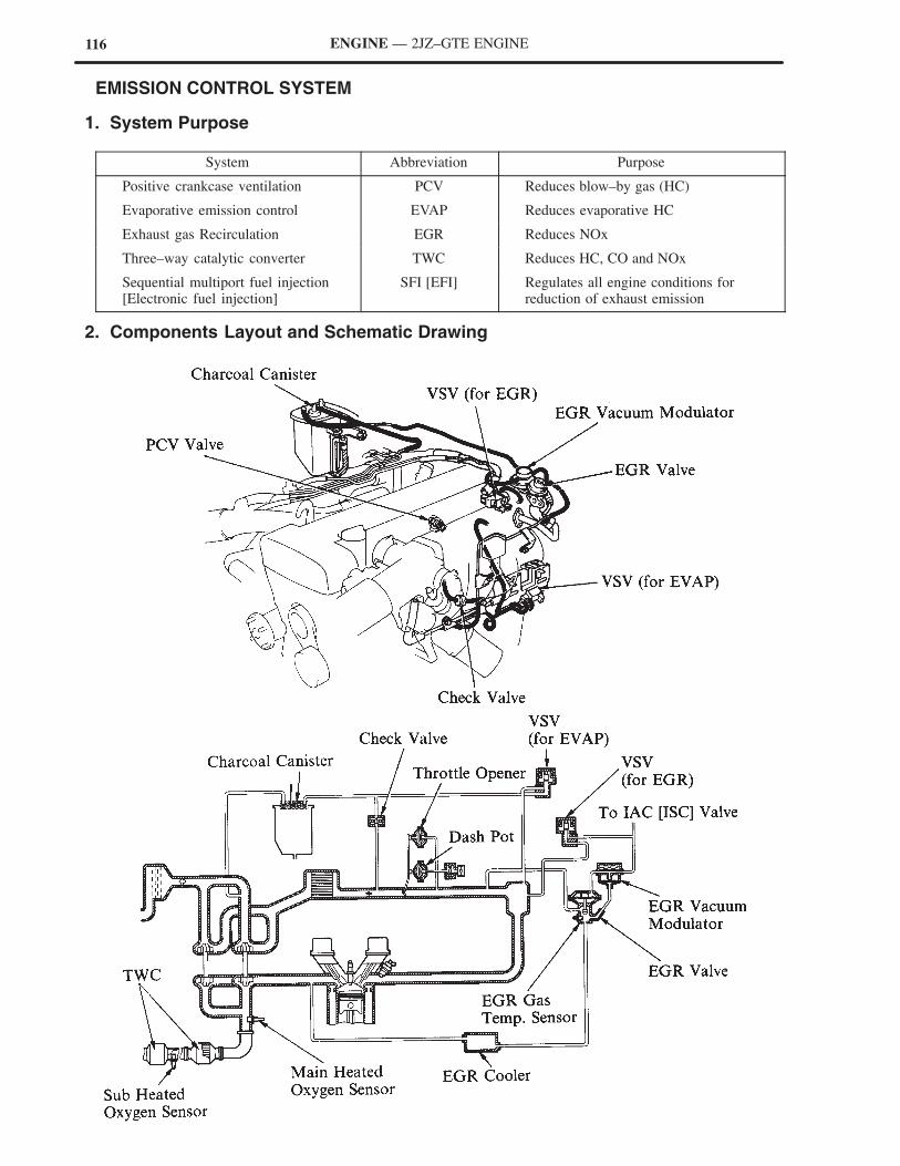
116 ENGINE — 2JZ–GTE ENGINE
� EMISSION CONTROL SYSTEM
1. System Purpose
System Abbreviation Purpose
Positive crankcase ventilation PCV Reduces blow–by gas (HC)
Evaporative emission control EVAP Reduces evaporative HC
Exhaust gas Recirculation EGR Reduces NOx
Three–way catalytic converter TWC Reduces HC, CO and NOx
Sequential multiport fuel injection[Electronic fuel injection]
SFI [EFI] Regulates all engine conditions forreduction of exhaust emission
2. Components Layout and Schematic Drawing
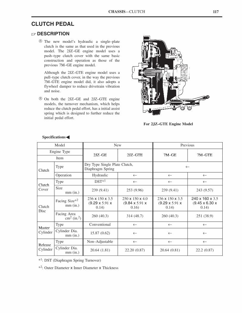
117CHASSIS—CLUTCH
CLUTCH PEDAL
� DESCRIPTION
� The new model’s hydraulic a single–plate
clutch is the same as that used in the previous
model. The 2JZ–GE engine model uses a
push–type clutch cover with the same basic
construction and operation as those of the
previous 7M–GE engine model.
Although the 2JZ–GTE engine model uses a
pull–type clutch cover, in the way the previous
7M–GTE engine model did, it also adopts a
flywheel damper to reduce drivetrain vibration
and noise.
� On both the 2JZ–GE and 2JZ–GTE engine
models, the turnover mechanism, which helps
reduce the clutch pedal effort, has a initial assist
spring which is designed to further reduce the
initial pedal effort.
For 2JZ–GTE Engine Model
�Specifications�
Model New Previous
Engine Type2JZ GE 2JZ GTE 7M GE 7M GTE
Item2JZ–GE 2JZ–GTE 7M–GE 7M–GTE
ClutchType
Dry Type Single Plate Clutch,Diaphragm Spring
←Clutch
Operation Hydraulic ← ← ←
ClutchType DST*1 ← ← ←
ClutchCover Size
mm (in.)239 (9.41) 253 (9.96) 239 (9.41) 243 (9.57)
ClutchDisc
Facing Size*2
mm (in.)
236 x 150 x 3.5(9.29 x 5.91 x
0.14)
250 x 150 x 4.0(9.84 x 5.91 x
0.16)
236 x 150 x 3.5(9.29 x 5.91 x
0.14)
240 x 160 x 3.5(9.45 x 6.30 x
0.14)Disc
Facing Area cm2 (in.2)
260 (40.3) 314 (48.7) 260 (40.3) 251 (38.9)
MasterType Conventional ← ← ←
MasterCylinder Cylinder Dia.
mm (in.)15.87 (0.62) ← ← ←
ReleaseType Non–Adjustable ← ← ←
ReleaseCylinder Cylinder Dia.
mm (in.)20.64 (1.81) 22.20 (0.87) 20.64 (0.81) 22.2 (0.87)
*1: DST (Diaphragm Spring Turnover)
*2: Outer Diameter x Inner Diameter x Thickness
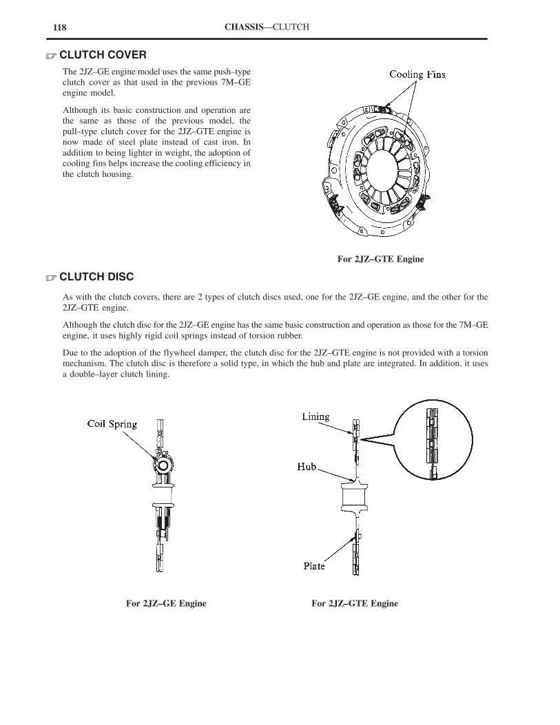
118 CHASSIS—CLUTCH
� CLUTCH COVER
The 2JZ–GE engine model uses the same push–type
clutch cover as that used in the previous 7M–GE
engine model.
Although its basic construction and operation are
the same as those of the previous model, the
pull–type clutch cover for the 2JZ–GTE engine is
now made of steel plate instead of cast iron. In
addition to being lighter in weight, the adoption of
cooling fins helps increase the cooling efficiency in
the clutch housing.
For 2JZ–GTE Engine
� CLUTCH DISC
As with the clutch covers, there are 2 types of clutch discs used, one for the 2JZ–GE engine, and the other for the
2JZ–GTE engine.
Although the clutch disc for the 2JZ–GE engine has the same basic construction and operation as those for the 7M–GE
engine, it uses highly rigid coil springs instead of torsion rubber.
Due to the adoption of the flywheel damper, the clutch disc for the 2JZ–GTE engine is not provided with a torsion
mechanism. The clutch disc is therefore a solid type, in which the hub and plate are integrated. In addition, it uses
a double–layer clutch lining.
For 2JZ–GTE EngineFor 2JZ–GE Engine
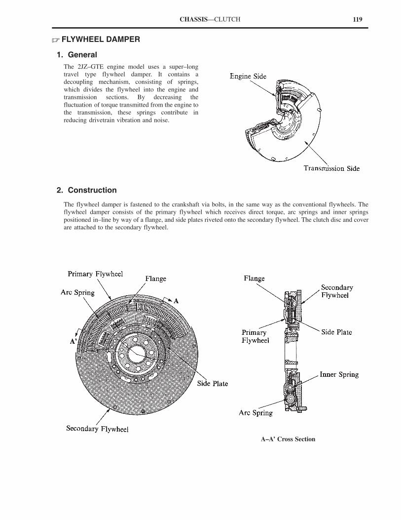
119CHASSIS—CLUTCH
� FLYWHEEL DAMPER
1. General
The 2JZ–GTE engine model uses a super–long
travel type flywheel damper. It contains a
decoupling mechanism, consisting of springs,
which divides the flywheel into the engine and
transmission sections. By decreasing the
fluctuation of torque transmitted from the engine to
the transmission, these springs contribute in
reducing drivetrain vibration and noise.
2. Construction
The flywheel damper is fastened to the crankshaft via bolts, in the same way as the conventional flywheels. The
flywheel damper consists of the primary flywheel which receives direct torque, arc springs and inner springs
positioned in–line by way of a flange, and side plates riveted onto the secondary flywheel. The clutch disc and cover
are attached to the secondary flywheel.
A–A’ Cross Section
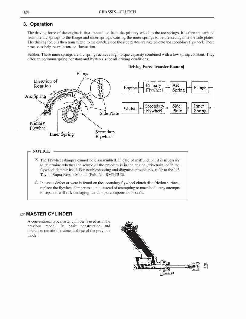
120
� The Flywheel damper cannot be disassembled. In case of malfunction, it is necessary
to determine whether the source of the problem is in the engine, drivetrain, or in the
flywheel damper itself. For troubleshooting and diagnosis procedures, refer to the ’93
Toyota Supra Repair Manual (Pub. No. RM343U2).
� In case a defect or wear is found on the secondary flywheel clutch disc friction surface,
replace the flywheel damper as a unit, instead of attempting to machine it. Any attempts
to repair it will risk damaging the damper components or seals.
NOTICE
CHASSIS—CLUTCH
3. Operation
The driving force of the engine is first transmitted from the primary wheel to the arc springs. It is then transmitted
from the arc springs to the flange and inner springs, causing the inner springs to be pressed against the side plates.
The driving force is then transmitted to the clutch, since the side plates are riveted onto the secondary flywheel. These
processes help restrain torque fluctuation.
Further, These inner springs are arc springs achieve high torque capacity combined with a low spring constant. They
offer an optimum spring constant and hysteresis for all driving conditions.
�Driving Force Transfer Route�
� MASTER CYLINDER
A conventional type master cylinder is used as in the
previous model. Its basic construction and
operation remain the same as those of the previous
model.
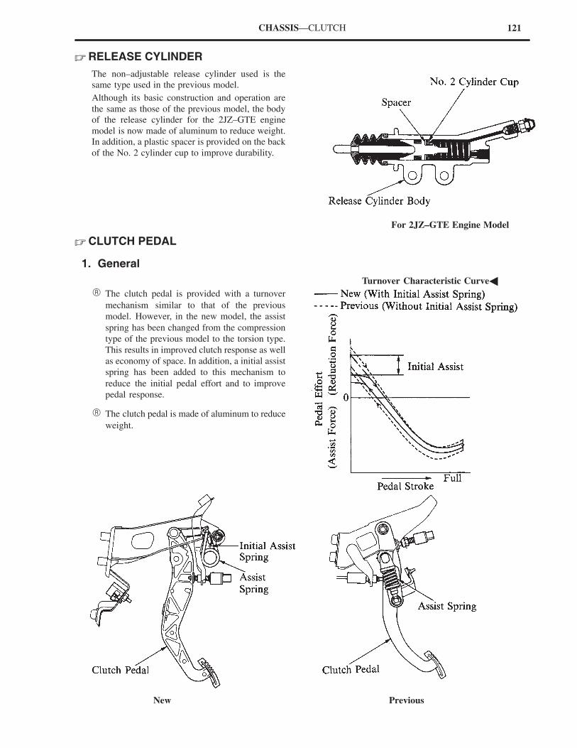
121
New Previous
CHASSIS—CLUTCH
� RELEASE CYLINDER
The non–adjustable release cylinder used is the
same type used in the previous model.
Although its basic construction and operation are
the same as those of the previous model, the body
of the release cylinder for the 2JZ–GTE engine
model is now made of aluminum to reduce weight.
In addition, a plastic spacer is provided on the back
of the No. 2 cylinder cup to improve durability.
For 2JZ–GTE Engine Model
� CLUTCH PEDAL
1. General
�Turnover Characteristic Curve�
� The clutch pedal is provided with a turnover
mechanism similar to that of the previous
model. However, in the new model, the assist
spring has been changed from the compression
type of the previous model to the torsion type.
This results in improved clutch response as well
as economy of space. In addition, a initial assist
spring has been added to this mechanism to
reduce the initial pedal effort and to improve
pedal response.
� The clutch pedal is made of aluminum to reduce
weight.
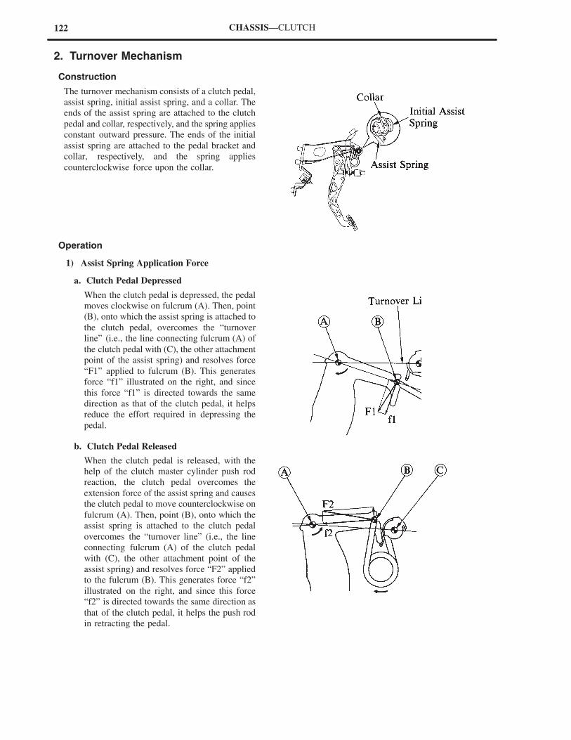
122 CHASSIS—CLUTCH
2. Turnover Mechanism
Construction
The turnover mechanism consists of a clutch pedal,
assist spring, initial assist spring, and a collar. The
ends of the assist spring are attached to the clutch
pedal and collar, respectively, and the spring applies
constant outward pressure. The ends of the initial
assist spring are attached to the pedal bracket and
collar, respectively, and the spring applies
counterclockwise force upon the collar.
Operation
1) Assist Spring Application Force
a. Clutch Pedal Depressed
When the clutch pedal is depressed, the pedal
moves clockwise on fulcrum (A). Then, point
(B), onto which the assist spring is attached to
the clutch pedal, overcomes the “turnover
line” (i.e., the line connecting fulcrum (A) of
the clutch pedal with (C), the other attachment
point of the assist spring) and resolves force
“F1” applied to fulcrum (B). This generates
force “f1” illustrated on the right, and since
this force “f1” is directed towards the same
direction as that of the clutch pedal, it helps
reduce the effort required in depressing the
pedal.
b. Clutch Pedal Released
When the clutch pedal is released, with the
help of the clutch master cylinder push rod
reaction, the clutch pedal overcomes the
extension force of the assist spring and causes
the clutch pedal to move counterclockwise on
fulcrum (A). Then, point (B), onto which the
assist spring is attached to the clutch pedal
overcomes the “turnover line” (i.e., the line
connecting fulcrum (A) of the clutch pedal
with (C), the other attachment point of the
assist spring) and resolves force “F2” applied
to the fulcrum (B). This generates force “f2”
illustrated on the right, and since this force
“f2” is directed towards the same direction as
that of the clutch pedal, it helps the push rod
in retracting the pedal.
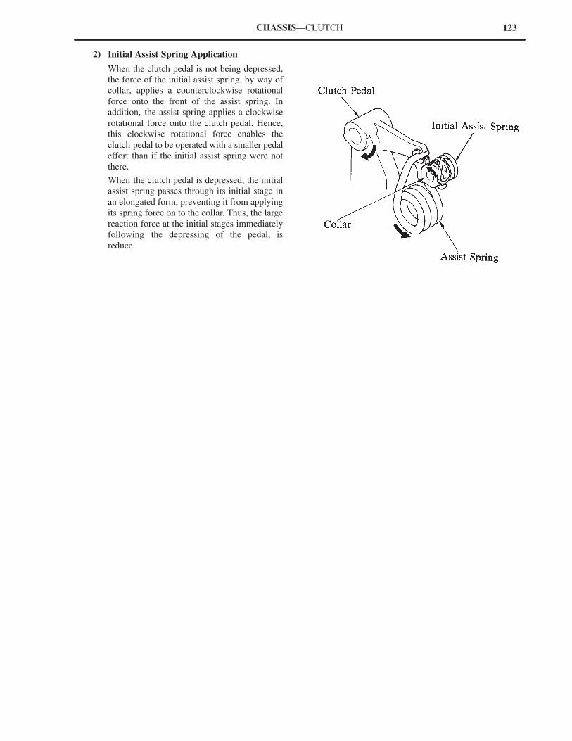
123CHASSIS—CLUTCH
2) Initial Assist Spring Application
When the clutch pedal is not being depressed,
the force of the initial assist spring, by way of
collar, applies a counterclockwise rotational
force onto the front of the assist spring. In
addition, the assist spring applies a clockwise
rotational force onto the clutch pedal. Hence,
this clockwise rotational force enables the
clutch pedal to be operated with a smaller pedal
effort than if the initial assist spring were not
there.
When the clutch pedal is depressed, the initial
assist spring passes through its initial stage in
an elongated form, preventing it from applying
its spring force on to the collar. Thus, the large
reaction force at the initial stages immediately
following the depressing of the pedal, is
reduce.
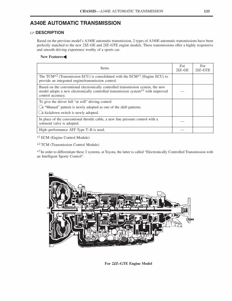
133CHASSIS—A340E AUTOMATIC TRANSMISSION
A340E AUTOMATIC TRANSMISSION
� DESCRIPTION
Based on the previous model’s A340E automatic transmission, 2 types of A340E automatic transmissions have been
perfectly matched to the new 2JZ–GE and 2JZ–GTE engine models. These transmissions offer a highly responsive
and smooth driving experience worthy of a sports car.
�New Features�
ItemsFor
2JZ–GEFor
2JZ–GTE
The TCM*2 (Transmission ECU) is consolidated with the ECM*1 (Engine ECU) toprovide an integrated engine/transmission control.
Based on the conventional electronically controlled transmission system, the newmodel adopts a new electronically controlled transmission system*3 with improvedcontrol accuracy.
—
To give the driver full “at will” driving control
�a “Manual” pattern is newly adopted as one of the shift patterns.
�a kickdown switch is newly adopted.
In place of the conventional throttle cable, a new line pressure control with asolenoid valve is adopted.
—
High–performance ATF Type T–II is used. —
*1 ECM (Engine Control Module)
*2 TCM (Transmission Control Module)
*3 In order to differentiate these 2 systems, at Toyota, the latter is called “Electronically Controlled Transmission with
an Intelligent Sporty Control”.
For 2JZ–GTE Engine Model
134 CHASSIS — A340E AUTOMATIC TRANSMISSION
�Specifications�
Model New Previous
Transmission Type A340E A340E A340E A340E
Engine Type2JZ GE 2JZ GTE 7M GE 7M GTE
Item2JZ–GE 2JZ–GTE 7M–GE 7M–GTE
1st 2.804 ← ←
2nd 1.531 ← ←
Gear Ratio 3rd 1.000 ← ←
4th (Overdrive) 0.705 ← ←
Reverse 2.393 ← ←
Fluid Capacity Liters (US qts, Imp.qts)
7.2 (7.6, 6.3) 8.2 (8.7, 7.2) 7.2 (7.6, 6.3)
Fluid TypeATF TypeDEXRON� II
ATF Type T–II ATF Type DEXRON� II
� TORQUE CONVERTER AND PLANETARY GEAR UNIT
The specifications of the torque converter and planetary gear unit have been revised to match the power output of
the new engine.
�Torque Converter�
Model New Previous
Transmission Type A340E A340E A340E A340E
Engine Type2JZ GE 2JZ GTE 7M GE 7M GTE
Item2JZ–GE 2JZ–GTE 7M–GE 7M–GTE
Converter Type3–Element, 1–step, 2–Phase,with Lock–Up Mechanism
←
Small Torque Ratio 1.900 2.000 ← 2.100
Nominal Diameter mm (in.) 254 (10.00) 272 (10.71) 254 (10.00) ←
�Planetary Gear Unit�
Model New Previous
Transmission Type A340E A340E A340E A340E
Engine Type2JZ GE 2JZ GTE 7M GE 7M GTE
Item2JZ–GE 2JZ–GTE 7M–GE 7M–GTE
C0 OD Direct Clutch 2 ← ← ←
C1 Forward Clutch No. of Discs 5 7 5 6
C2 Direct Clutch 4 5 4 ←
B0 OD Brake No. of Discs 4 5 ← ←
B1 2nd Coast Brake Band Width mm (in.) 40 (1.57) ← ← ←
B2 2nd BrakeNo of Discs
5 ← ← ←
B3 1st & Reverse BrakeNo. of Discs
6 7 6 7
F0 OD One–Way Clutch 24 ← ← ←
F1 No. 1 One–Way Clutch No. of Sprags 22 ← ← ←
F2 No. 2 One–Way Clutch
p g
28 ← ← ←
No. of Sun Gear Teeth 42 ← ← ←
Front Planetary Gear No. of Pinion Gear Teeth 19 ← ← ←y
No. of Ring Gear Teeth 79 ← ← ←
No. of Sun Gear Teeth 33 ← ← ←
Rear Planetary Gear No. of Pinion Gear Teeth 23 ← ← ←y
No. of Ring Gear Teeth 79 ← ← ←
No. of Sun Gear Teeth 33 ← ← ←
OD Planetary Gear No. of Pinion Gear Teeth 23 ← ← ←y
No. of Ring Gear Teeth 79 ← ← ←
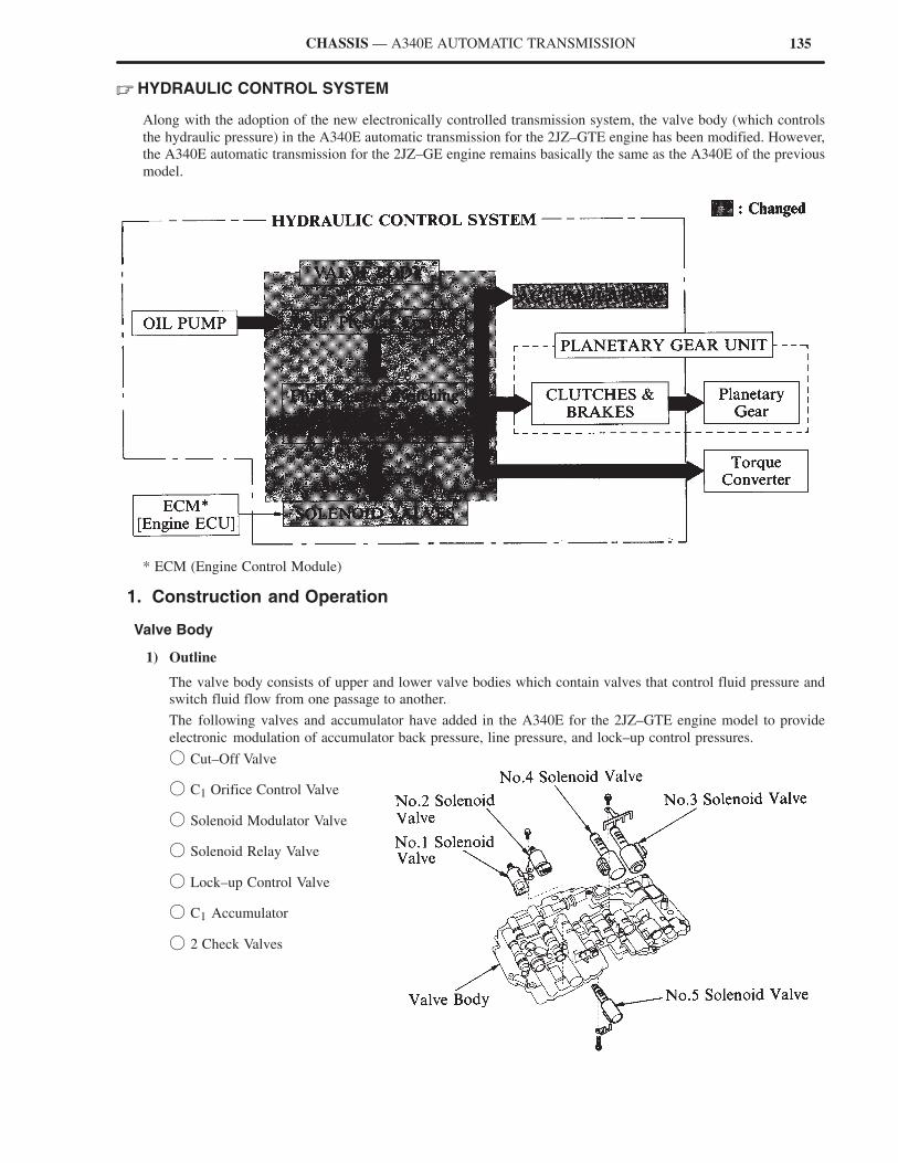
135CHASSIS — A340E AUTOMATIC TRANSMISSION
� HYDRAULIC CONTROL SYSTEM
Along with the adoption of the new electronically controlled transmission system, the valve body (which controls
the hydraulic pressure) in the A340E automatic transmission for the 2JZ–GTE engine has been modified. However,
the A340E automatic transmission for the 2JZ–GE engine remains basically the same as the A340E of the previous
model.
* ECM (Engine Control Module)
1. Construction and Operation
Valve Body
1) Outline
The valve body consists of upper and lower valve bodies which contain valves that control fluid pressure and
switch fluid flow from one passage to another.
The following valves and accumulator have added in the A340E for the 2JZ–GTE engine model to provide
electronic modulation of accumulator back pressure, line pressure, and lock–up control pressures.
� Cut–Off Valve
� C1 Orifice Control Valve
� Solenoid Modulator Valve
� Solenoid Relay Valve
� Lock–up Control Valve
� C1 Accumulator
� 2 Check Valves
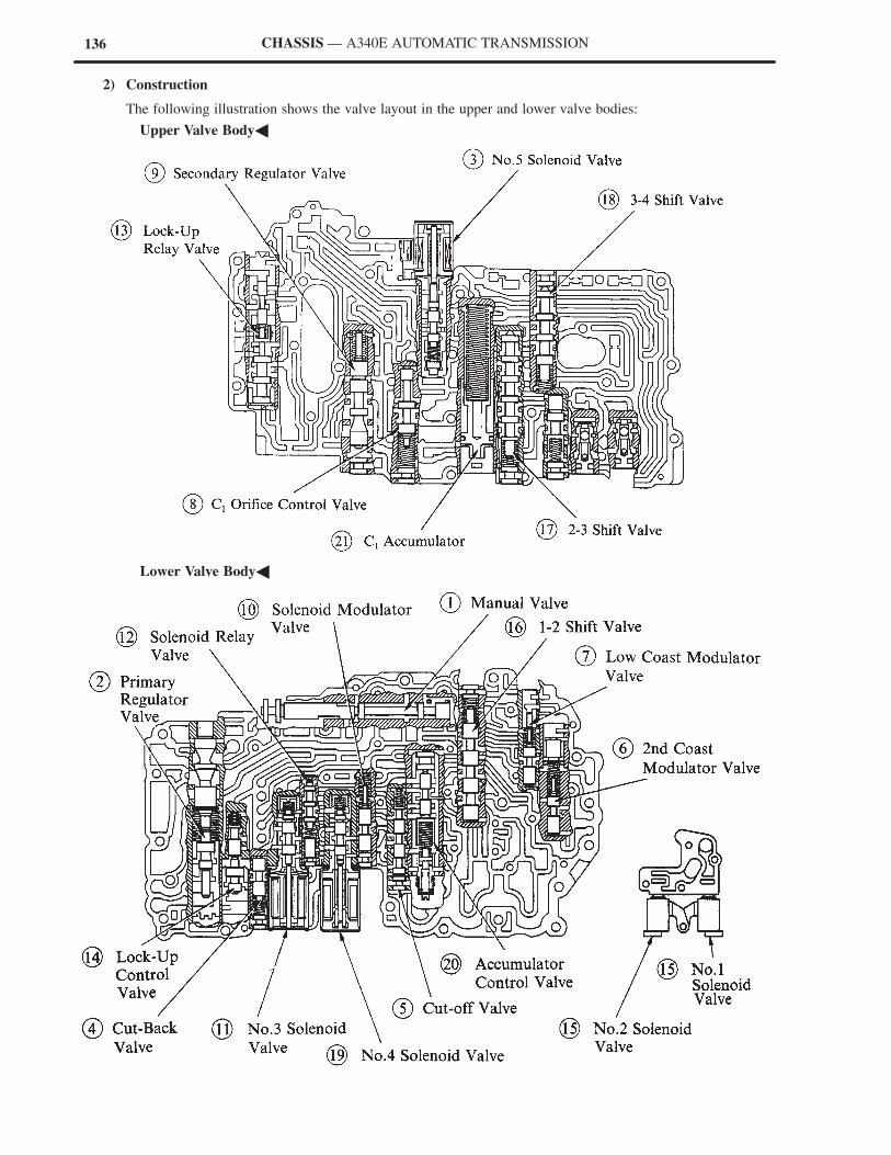
136 CHASSIS — A340E AUTOMATIC TRANSMISSION
2) Construction
The following illustration shows the valve layout in the upper and lower valve bodies:
�Upper Valve Body�
�Lower Valve Body�
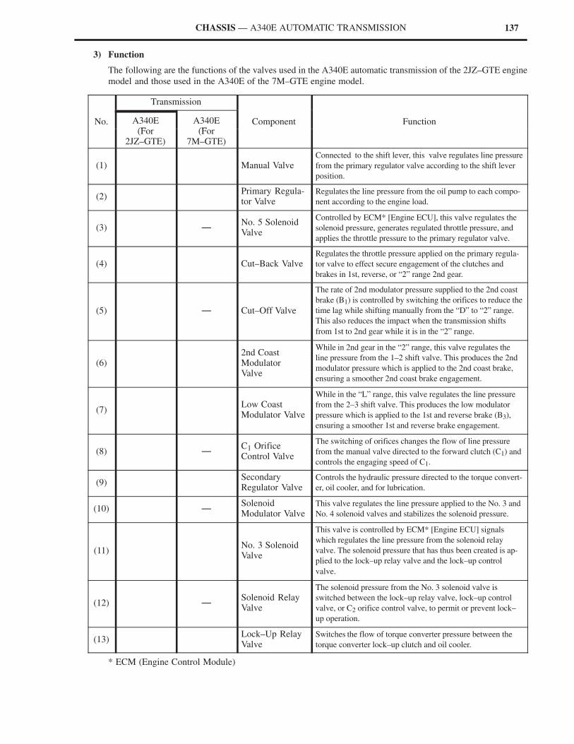
137CHASSIS — A340E AUTOMATIC TRANSMISSION
3) Function
The following are the functions of the valves used in the A340E automatic transmission of the 2JZ–GTE engine
model and those used in the A340E of the 7M–GTE engine model.
Transmission
No. A340E(F
A340E(F
Component Function(For
2JZ–GTE)(For
7M–GTE)
p
(1) Manual ValveConnected to the shift lever, this valve regulates line pressure
from the primary regulator valve according to the shift lever
position.
(2) Primary Regula-tor Valve
Regulates the line pressure from the oil pump to each compo-
nent according to the engine load.
(3) —No. 5 SolenoidValve
Controlled by ECM* [Engine ECU], this valve regulates the
solenoid pressure, generates regulated throttle pressure, and
applies the throttle pressure to the primary regulator valve.
(4) Cut–Back ValveRegulates the throttle pressure applied on the primary regula-
tor valve to effect secure engagement of the clutches and
brakes in 1st, reverse, or “2” range 2nd gear.
(5) — Cut–Off Valve
The rate of 2nd modulator pressure supplied to the 2nd coast
brake (B1) is controlled by switching the orifices to reduce the
time lag while shifting manually from the “D” to “2” range.
This also reduces the impact when the transmission shifts
from 1st to 2nd gear while it is in the “2” range.
(6) 2nd Coast ModulatorValve
While in 2nd gear in the “2” range, this valve regulates the
line pressure from the 1–2 shift valve. This produces the 2nd
modulator pressure which is applied to the 2nd coast brake,
ensuring a smoother 2nd coast brake engagement.
(7) Low Coast Modulator Valve
While in the “L” range, this valve regulates the line pressure
from the 2–3 shift valve. This produces the low modulator
pressure which is applied to the 1st and reverse brake (B3),
ensuring a smoother 1st and reverse brake engagement.
(8) —C1 OrificeControl Valve
The switching of orifices changes the flow of line pressure
from the manual valve directed to the forward clutch (C1) and
controls the engaging speed of C1.
(9) SecondaryRegulator Valve
Controls the hydraulic pressure directed to the torque convert-
er, oil cooler, and for lubrication.
(10) —Solenoid Modulator Valve
This valve regulates the line pressure applied to the No. 3 and
No. 4 solenoid valves and stabilizes the solenoid pressure.
(11) No. 3 SolenoidValve
This valve is controlled by ECM* [Engine ECU] signals
which regulates the line pressure from the solenoid relay
valve. The solenoid pressure that has thus been created is ap-
plied to the lock–up relay valve and the lock–up control
valve.
(12) —Solenoid RelayValve
The solenoid pressure from the No. 3 solenoid valve is
switched between the lock–up relay valve, lock–up control
valve, or C2 orifice control valve, to permit or prevent lock–
up operation.
(13) Lock–Up RelayValve
Switches the flow of torque converter pressure between the
torque converter lock–up clutch and oil cooler.
* ECM (Engine Control Module)
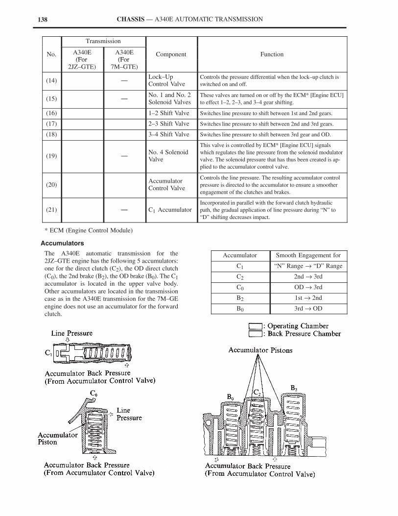
138 CHASSIS — A340E AUTOMATIC TRANSMISSION
Transmission
No. A340E(For
A340E(For
Component Function(For
2JZ–GTE)(For
7M–GTE)
p
(14) —Lock–UpControl Valve
Controls the pressure differential when the lock–up clutch is
switched on and off.
(15) —No. 1 and No. 2Solenoid Valves
These valves are turned on or off by the ECM* [Engine ECU]
to effect 1–2, 2–3, and 3–4 gear shifting.
(16) 1–2 Shift Valve Switches line pressure to shift between 1st and 2nd gears.
(17) 2–3 Shift Valve Switches line pressure to shift between 2nd and 3rd gears.
(18) 3–4 Shift Valve Switches line pressure to shift between 3rd gear and OD.
(19) —No. 4 SolenoidValve
This valve is controlled by ECM* [Engine ECU] signals
which regulates the line pressure from the solenoid modulator
valve. The solenoid pressure that has thus been created is ap-
plied to the accumulator control valve.
(20) AccumulatorControl Valve
Controls the line pressure. The resulting accumulator control
pressure is directed to the accumulator to ensure a smoother
engagement of the clutches and brakes.
(21) — C1 AccumulatorIncorporated in parallel with the forward clutch hydraulic
path, the gradual application of line pressure during “N” to
“D” shifting decreases impact.
* ECM (Engine Control Module)
Accumulators
The A340E automatic transmission for the
2JZ–GTE engine has the following 5 accumulators:
one for the direct clutch (C2), the OD direct clutch
(C0), the 2nd brake (B2), the OD brake (B0). The C1
accumulator is located in the upper valve body.
Other accumulators are located in the transmission
case as in the A340E transmission for the 7M–GE
engine does not use an accumulator for the forward
clutch.
Accumulator Smooth Engagement for
C1 “N” Range → “D” Range
C2 2nd → 3rd
C0 OD → 3rd
B2 1st → 2nd
B0 3rd → OD
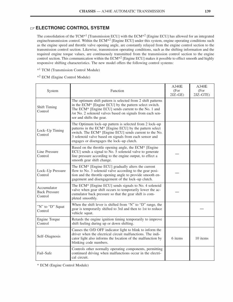
139CHASSIS — A340E AUTOMATIC TRANSMISSION
� ELECTRONIC CONTROL SYSTEM
The consolidation of the TCM*1 [Transmission ECU] with the ECM*2 [Engine ECU] has allowed for an integrated
engine/transmission control. Within the ECM*2 [Engine ECU] under this system, engine operating conditions such
as the engine speed and throttle valve opening angle, are constantly relayed from the engine control section to the
transmission control section. Likewise, transmission operating conditions, such as the shifting information and the
required engine torque values, are continuously transmitted from the transmission control section to the engine
control section. This communication within the ECM*2 [Engine ECU] makes it possible to effect smooth and highly
responsive shifting characteristics. The new model offers the following control systems:
*1 TCM (Transmission Control Module)
*2 ECM (Engine Control Module)
A340E A340E
System Function
A340E(For
A340E(ForSystem Function (For
2JZ–GE)(For
2JZ–GTE)
Shift TimingControl
The optimum shift pattern is selected from 2 shift patternsin the ECM* [Engine ECU] by the pattern select switch.The ECM* [Engine ECU] sends current to the No. 1 and/or No. 2 solenoid valves based on signals from each sen-sor and shifts the gear.
Lock–Up TimingControl
The Optimum lock–up pattern is selected from 2 lock–uppatterns in the ECM* [Engine ECU] by the pattern selectswitch. The ECM* [Engine ECU] sends current to the No.3 solenoid valve based on signals from each sensor andengages or disengages the lock–up clutch.
Line PressureControl
Based on the throttle opening angle, the ECM* [EngineECU] sends a signal to No. 5 solenoid valve to generateline pressure according to the engine output, to effect asmooth gear shift change.
—
Lock–Up PressureControl
The ECM* [Engine ECU] gradually alters the currentflow to No. 3 solenoid valve according to the gear posi-tion and the throttle opening angle to provide smooth en-gagement and disengagement of the lock–up clutch.
—
AccumulatorBack PressureControl
The ECM* [Engine ECU] sends signals to No. 4 solenoidvalve when gear shift occurs to temporarily lower the ac-cumulator back pressure so that the gear shift is com-pleted smoothly.
—
”N” to “D” SquatControl
When the shift lever is shifted from “N” to “D” range, thegear is temporarily shifted to 3rd and then to 1st to reducevehicle squat.
—
Engine TorqueControl
Retards the engine ignition timing temporarily to improveshift feeling during up or down shifting.
Self–Diagnosis
Causes the O/D OFF indicator light to blink to inform thedriver when the electrical circuit malfunctions. The indi-cator light also informs the location of the malfunction byblinking code numbers.
6 items
10 items
Fail–SafeControls other normally operating components, permittingcontinued driving when malfunctions occur in the electri-cal circuit.
* ECM (Engine Control Module)
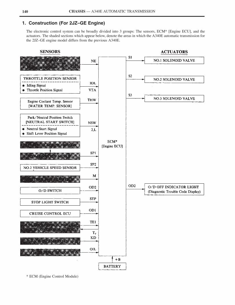
140 CHASSIS — A340E AUTOMATIC TRANSMISSION
1. Construction (For 2JZ–GE Engine)
The electronic control system can be broadly divided into 3 groups: The sensors, ECM* [Engine ECU], and the
actuators. The shaded sections which appear below, denote the areas in which the A340E automatic transmission for
the 2JZ–GE engine model differs from the previous A340E.
* ECM (Engine Control Module)
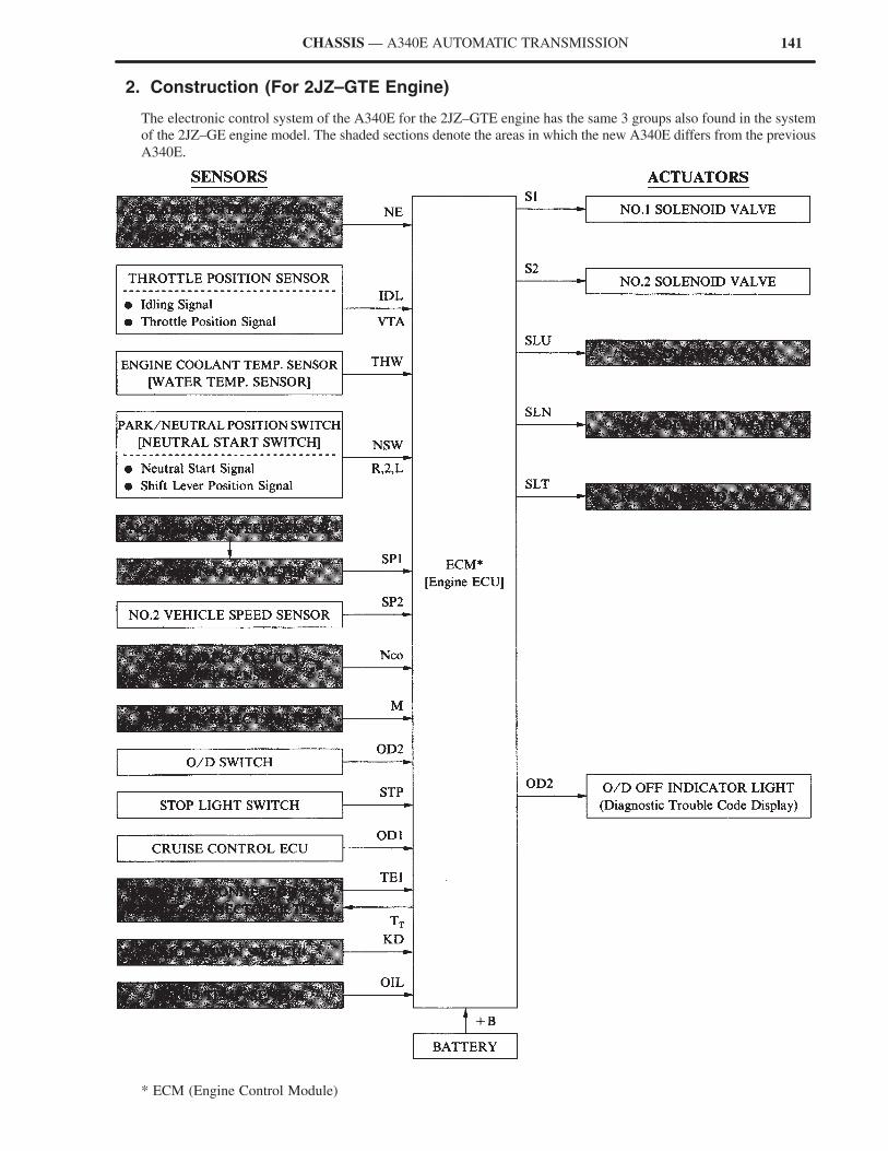
141CHASSIS — A340E AUTOMATIC TRANSMISSION
2. Construction (For 2JZ–GTE Engine)
The electronic control system of the A340E for the 2JZ–GTE engine has the same 3 groups also found in the system
of the 2JZ–GE engine model. The shaded sections denote the areas in which the new A340E differs from the previous
A340E.
* ECM (Engine Control Module)

142 CHASSIS — A340E AUTOMATIC TRANSMISSION
3. Wiring Diagram
*1 For 2JZ–GTE Engine Model
*2 For 2JZ–GE Engine Model
*3 ECM (Engine Control Module)
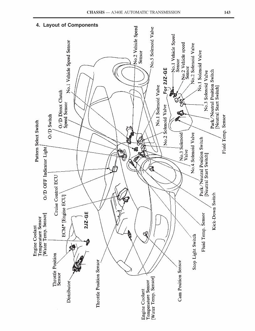
143CHASSIS — A340E AUTOMATIC TRANSMISSION
4. Layout of Components
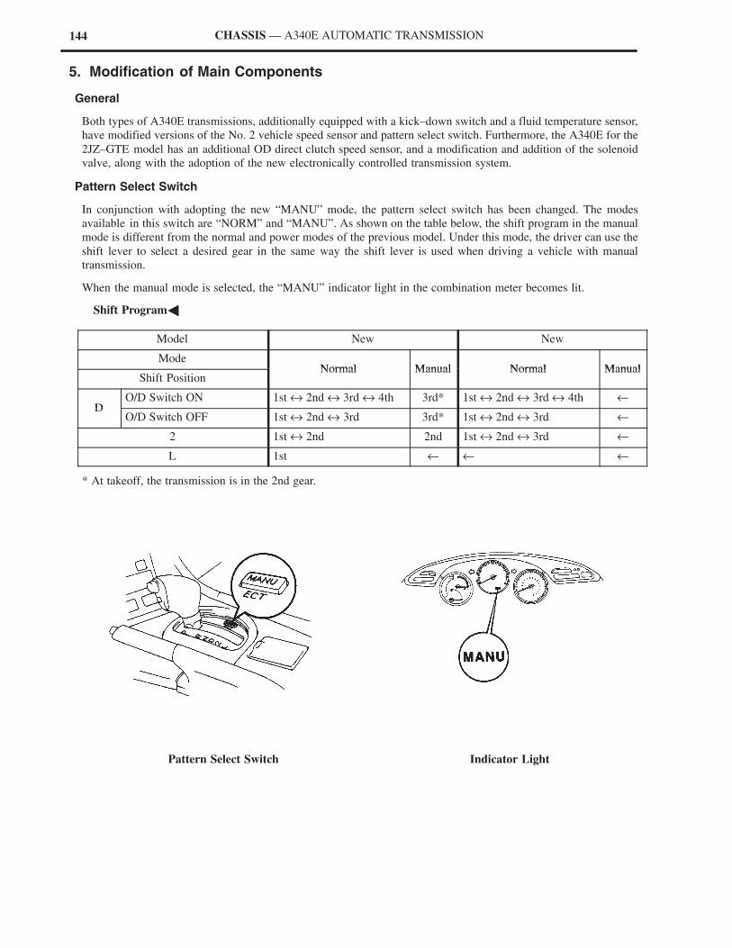
144 CHASSIS — A340E AUTOMATIC TRANSMISSION
5. Modification of Main Components
General
Both types of A340E transmissions, additionally equipped with a kick–down switch and a fluid temperature sensor,
have modified versions of the No. 2 vehicle speed sensor and pattern select switch. Furthermore, the A340E for the
2JZ–GTE model has an additional OD direct clutch speed sensor, and a modification and addition of the solenoid
valve, along with the adoption of the new electronically controlled transmission system.
Pattern Select Switch
In conjunction with adopting the new “MANU” mode, the pattern select switch has been changed. The modes
available in this switch are “NORM” and “MANU”. As shown on the table below, the shift program in the manual
mode is different from the normal and power modes of the previous model. Under this mode, the driver can use the
shift lever to select a desired gear in the same way the shift lever is used when driving a vehicle with manual
transmission.
When the manual mode is selected, the “MANU” indicator light in the combination meter becomes lit.
�Shift Program�
Model New New
ModeNormal Manual Normal Manual
Shift PositionNormal Manual Normal Manual
DO/D Switch ON 1st ↔ 2nd ↔ 3rd ↔ 4th 3rd* 1st ↔ 2nd ↔ 3rd ↔ 4th ←
DO/D Switch OFF 1st ↔ 2nd ↔ 3rd 3rd* 1st ↔ 2nd ↔ 3rd ←
2 1st ↔ 2nd 2nd 1st ↔ 2nd ↔ 3rd ←
L 1st ← ← ←
* At takeoff, the transmission is in the 2nd gear.
Pattern Select Switch Indicator Light
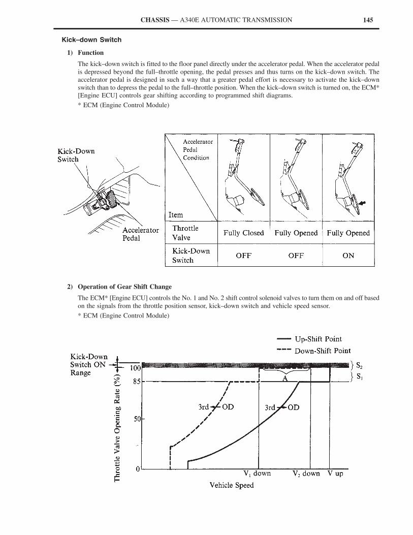
145CHASSIS — A340E AUTOMATIC TRANSMISSION
Kick–down Switch
1) Function
The kick–down switch is fitted to the floor panel directly under the accelerator pedal. When the accelerator pedal
is depressed beyond the full–throttle opening, the pedal presses and thus turns on the kick–down switch. The
accelerator pedal is designed in such a way that a greater pedal effort is necessary to activate the kick–down
switch than to depress the pedal to the full–throttle position. When the kick–down switch is turned on, the ECM*
[Engine ECU] controls gear shifting according to programmed shift diagrams.
* ECM (Engine Control Module)
2) Operation of Gear Shift Change
The ECM* [Engine ECU] controls the No. 1 and No. 2 shift control solenoid valves to turn them on and off based
on the signals from the throttle position sensor, kick–down switch and vehicle speed sensor.
* ECM (Engine Control Module)
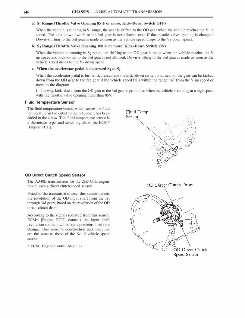
146 CHASSIS — A340E AUTOMATIC TRANSMISSION
a. S1 Range (Throttle Valve Opening 85% or more, Kick–Down Switch OFF)
When the vehicle is running in S1 range, the gear is shifted to the OD gear when the vehicle reaches the V up
speed. The kick–down switch to the 3rd gear is not allowed even if the throttle valve opening is changed.
Down–shifting to the 3rd gear is made as soon as the vehicle speed drops to the V1 down speed.
b. S2 Range (Throttle Valve Opening 100% or more, Kick–Down Switch ON)
When the vehicle is running in S2 range, up–shifting to the OD gear is made when the vehicle reaches the V
up speed and kick–down to the 3rd gear is not allowed. Down–shifting to the 3rd gear is made as soon as the
vehicle speed drops to the V2 down speed.
c. When the accelerator pedal is depressed S1 to S2
When the accelerator pedal is further depressed and the kick–down switch is turned on, the gear can be kicked
down from the OD gear to the 3rd gear if the vehicle speed falls within the range “A” from the V up speed or
more in the diagram.
In this way, kick–down from the OD gear to the 3rd gear is prohibited when the vehicle is running at a high speed
with the throttle valve opening more than 85%.
Fluid Temperature Sensor
The fluid temperature sensor, which senses the fluid
temperature in the outlet to the oil cooler, has been
added in the elbow. This fluid temperature sensor is
a thermistor type, and sends signals to the ECM*
[Engine ECU].
OD Direct Clutch Speed Sensor
The A340E transmission for the 2JZ–GTE engine
model uses a direct clutch speed sensor.
Fitted to the transmission case, this sensor detects
the revolution of the OD input shaft from the 1st
through 3rd gears, based on the revolution of the OD
direct clutch drum.
According to the signals received from this sensor,
ECM* [Engine ECU] controls the input shaft
revolution so that it will effect a predetermined rpm
change. This sensor’s construction and operation
are the same as those of the No. 2 vehicle speed
sensor.
* ECM (Engine Control Module)
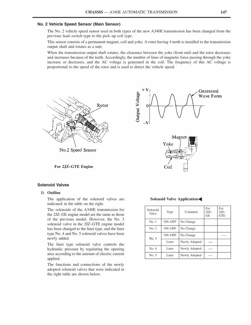
147CHASSIS — A340E AUTOMATIC TRANSMISSION
No. 2 Vehicle Speed Sensor (Main Sensor)
The No. 2 vehicle speed sensor used in both types of the new A340E transmission has been changed from the
previous lead–switch type to the pick–up coil type.
This sensor consists of a permanent magnet, coil and yoke. A rotor having 4 teeth is installed to the transmission
output shaft and rotates as a unit.
When the transmission output shaft rotates, the clearance between the yoke (front end) and the rotor decreases
and increases because of the teeth. Accordingly, the number of lines of magnetic force passing through the yoke
increase or decreases, and the AC voltage is generated in the coil. The frequency of this AC voltage is
proportional to the speed of the rotor and is used to detect the vehicle speed.
For 2JZ–GTE Engine
Solenoid Valves
1) Outline
The application of the solenoid valves are
indicated in the table on the right.
The solenoids of the A340E transmission for
the 2JZ–GE engine model are the same as those
of the previous model. However, the No. 3
solenoid valve in the 2JZ–GTE engine model
has been changed to the liner type, and the liner
type No. 4 and No. 5 solenoid valves have been
newly added.
The liner type solenoid valve controls the
hydraulic pressure by regulating the opening
area according to the amount of electric current
applied.
The functions and connections of the newly
adopted solenoid valves that were indicated in
the right table are shown below.
�Solenoid Valve Application�
SolenoidValve
Type CommentFor2JZ–GE
For2JZ–GTE
No. 1 ON–OFF No Change
No. 2 ON–OFF No Change
No 3ON–OFF No Change —
No. 3Liner Newly Adopted —
No. 4 Liner Newly Adopted —
No. 5 Liner Newly Adopted —
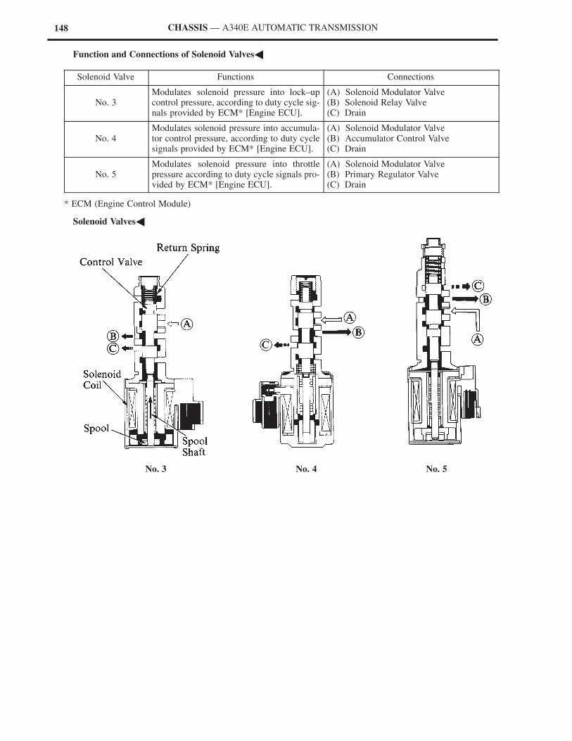
148 CHASSIS — A340E AUTOMATIC TRANSMISSION
�Function and Connections of Solenoid Valves�
Solenoid Valve Functions Connections
No. 3Modulates solenoid pressure into lock–upcontrol pressure, according to duty cycle sig-nals provided by ECM* [Engine ECU].
(A) Solenoid Modulator Valve(B) Solenoid Relay Valve(C) Drain
No. 4Modulates solenoid pressure into accumula-tor control pressure, according to duty cyclesignals provided by ECM* [Engine ECU].
(A) Solenoid Modulator Valve(B) Accumulator Control Valve(C) Drain
No. 5Modulates solenoid pressure into throttlepressure according to duty cycle signals pro-vided by ECM* [Engine ECU].
(A) Solenoid Modulator Valve(B) Primary Regulator Valve(C) Drain
* ECM (Engine Control Module)
�Solenoid Valves�
No. 3 No. 4 No. 5

149CHASSIS — A340E AUTOMATIC TRANSMISSION
Function of ECU
1) General
The shift and lock–up timing has been changed in connection with the adoption of the manual mode.
Moveover, an engine torque control has been added to provide a smooth gear shifting operation. On the 2JZ–GTE
engine model, a lock–up pressure control, accumulator back pressure control, and line pressure control have been
added to provide smooth shifting characteristics.
2) Shift and Lock–Up Timing Control
On the new model, “normal” and “manual” modes can be selected with the select switch.
When the manual mode signals are input to ECM* [Engine ECU] by engaging the pattern select switch to the
manual mode, ECM sends control signals to the No. 1 and No. 2 solenoid valves so that each gear is engaged
according to the shift lever position. (Hence, the transmission is in 1st gear when the shift lever is in “L”, 2nd
gear when it is in “2”, and 3rd gear when it is in “D”.)
However, takeoff in the D range is effected in the 2nd gear.
To summarize, the manual mode of the new model does not effect automatic shift–up and shift–down operations
as the normal and power modes of the previous model did. Instead, the shift lever position selected is the gear
speed selected.
a. Shift Program Switchover Control
i) When Restarting Engine
To prevent the driver from forgetting to
release the manual mode of the pattern select
switch, even if the pattern select switch
remains in manual mode the shift program
automatically changes the mode to the
normal mode when the ignition switch is
turned from ON to ACC or OFF, or it is then
turned back to ON again. In addition, the
“MANU” mode indicator light in the
combination meter is turned off.
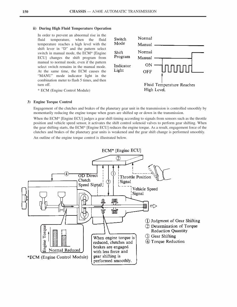
150 CHASSIS — A340E AUTOMATIC TRANSMISSION
ii) During High Fluid Temperature Operation
In order to prevent an abnormal rise in the
fluid temperature, when the fluid
temperature reaches a high level with the
shift lever in “D” and the pattern select
switch in manual mode, the ECM* [Engine
ECU] changes the shift program from
manual to normal mode, even if the pattern
select switch remains in the manual mode.
At the same time, the ECM causes the
“MANU” mode indicator light in the
combination meter to flash 5 times, and then
turn off.
* ECM (Engine Control Module)
3) Engine Torque Control
Engagement of the clutches and brakes of the planetary gear unit in the transmission is controlled smoothly by
momentarily reducing the engine torque when gears are shifted up or down in the transmission.
When the ECM* [Engine ECU] judges a gear shift timing according to signals from sensors such as the throttle
position and vehicle speed sensor, it activates the shift control solenoid valves to perform gear shifting. When
the gear shifting starts, the ECM* [Engine ECU] reduces the engine torque. As a result, engagement force of the
clutches and brakes of the planetary gear units is weakened and the gear shift change is performed smoothly.
An outline of the engine torque control is illustrated below.
151CHASSIS — A340E AUTOMATIC TRANSMISSION
4) Lock–Up Pressure Control
Lock–up control is performed by electronically controlling the lock–up control valve which modulates the
engagement pressure acting on the lock–up clutch, and lock–up pressure which activates the lock–up relay valve
that switches engagement and disengagement of the clutch. As a result, these valves are activated gradually and
smooth engagement and disengagement are performed.
Lock–up pressure control is performed by changing the duty signal to the No. 3 solenoid valve which is sent to
the valve body from the ECU* [Engine ECU]. When the ECU* [Engine ECU] according to the memorized
lock–up pattern selected based on the gear shift position and throttle valve opening angle, implements lock–up
ON or OFF, it changes the duty ratio of the signals to the solenoid valve, and engages or disengages the clutch
smoothly. However, the clutch is disengaged immediately when the foregoing lock–up prohibit conditions are
present while the lock–up clutch is engaged.
5) Accumulator Back Pressure Control
During gear shifting, the accumulator temporarily accumulates the line pressure according to a difference
between the line pressure (which acts on the operation chamber of the piston and engages the clutches and brakes
of the planetary gear unit) and the accumulator back pressure acting on the back pressure chamber. The
accumulator then gradually applies the stored line pressure to the clutches and brakes to perform gear shifting
smoothly. The accumulator back pressure that acts on the back pressure chamber is controlled electronically.
Therefore, gear shifting is performed smoothly regardless of a fluctuation in the engine torque or a change in
the friction characteristics.
The accumulator back pressure is controlled by the No. 4 solenoid valve fitted to the valve body. The solenoid
valve itself is controlled by the ECM* [Engine ECU] changing the duty ratio to the valve according to the gear
shifting mode, the throttle valve opening angle, the OD direct clutch drum speed and the vehicle speed.
*ECM (Engine Control Module)
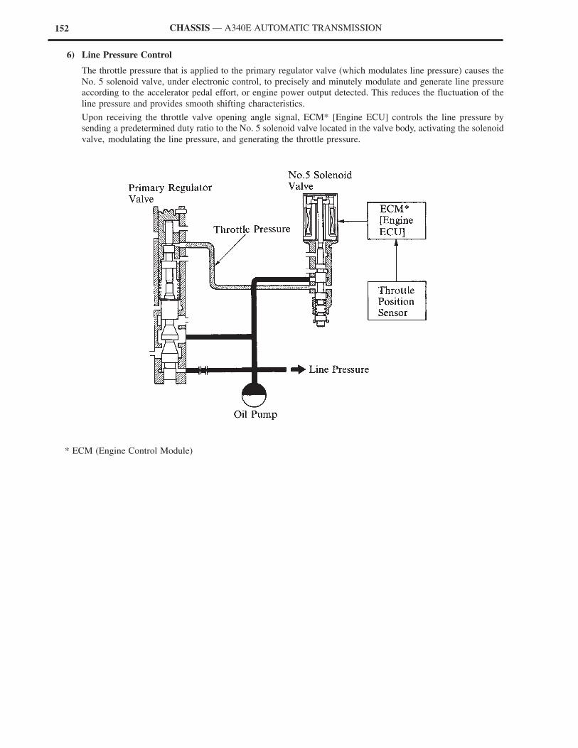
152 CHASSIS — A340E AUTOMATIC TRANSMISSION
6) Line Pressure Control
The throttle pressure that is applied to the primary regulator valve (which modulates line pressure) causes the
No. 5 solenoid valve, under electronic control, to precisely and minutely modulate and generate line pressure
according to the accelerator pedal effort, or engine power output detected. This reduces the fluctuation of the
line pressure and provides smooth shifting characteristics.
Upon receiving the throttle valve opening angle signal, ECM* [Engine ECU] controls the line pressure by
sending a predetermined duty ratio to the No. 5 solenoid valve located in the valve body, activating the solenoid
valve, modulating the line pressure, and generating the throttle pressure.
* ECM (Engine Control Module)
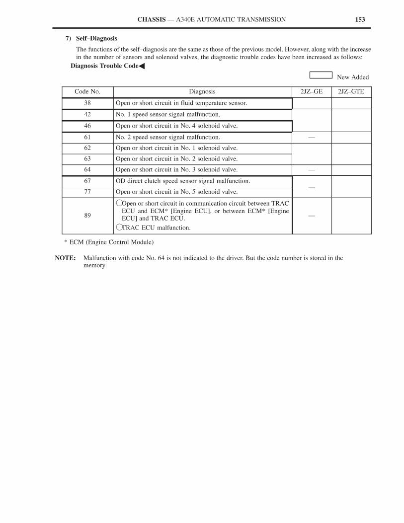
153CHASSIS — A340E AUTOMATIC TRANSMISSION
7) Self–Diagnosis
The functions of the self–diagnosis are the same as those of the previous model. However, along with the increase
in the number of sensors and solenoid valves, the diagnostic trouble codes have been increased as follows:
�Diagnosis Trouble Code�
New Added
Code No. Diagnosis 2JZ–GE 2JZ–GTE
38 Open or short circuit in fluid temperature sensor.
42 No. 1 speed sensor signal malfunction.
46 Open or short circuit in No. 4 solenoid valve.
61 No. 2 speed sensor signal malfunction. —
62 Open or short circuit in No. 1 solenoid valve.
63 Open or short circuit in No. 2 solenoid valve.
64 Open or short circuit in No. 3 solenoid valve. —
67 OD direct clutch speed sensor signal malfunction.
77 Open or short circuit in No. 5 solenoid valve.—
89
�Open or short circuit in communication circuit between TRAC
ECU and ECM* [Engine ECU], or between ECM* [EngineECU] and TRAC ECU.
�TRAC ECU malfunction.
—
* ECM (Engine Control Module)
NOTE: Malfunction with code No. 64 is not indicated to the driver. But the code number is stored in thememory.
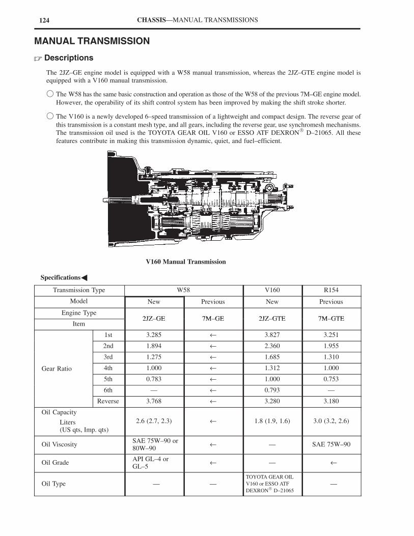
124 CHASSIS—MANUAL TRANSMISSIONS
MANUAL TRANSMISSION
� Descriptions
The 2JZ–GE engine model is equipped with a W58 manual transmission, whereas the 2JZ–GTE engine model is
equipped with a V160 manual transmission.
� The W58 has the same basic construction and operation as those of the W58 of the previous 7M–GE engine model.
However, the operability of its shift control system has been improved by making the shift stroke shorter.
� The V160 is a newly developed 6–speed transmission of a lightweight and compact design. The reverse gear of
this transmission is a constant mesh type, and all gears, including the reverse gear, use synchromesh mechanisms.
The transmission oil used is the TOYOTA GEAR OIL V160 or ESSO ATF DEXRON� D–21065. All these
features contribute in making this transmission dynamic, quiet, and fuel–efficient.
V160 Manual Transmission
�Specifications�
Transmission Type W58 V160 R154
Model New Previous New Previous
Engine Type2JZ GE 7M GE 2JZ GTE 7M GTE
Item2JZ–GE 7M–GE 2JZ–GTE 7M–GTE
1st 3.285 ← 3.827 3.251
2nd 1.894 ← 2.360 1.955
3rd 1.275 ← 1.685 1.310
Gear Ratio 4th 1.000 ← 1.312 1.000
5th 0.783 ← 1.000 0.753
6th — ← 0.793 —
Reverse 3.768 ← 3.280 3.180
Oil Capacity
Liters (US qts, Imp. qts)
2.6 (2.7, 2.3) ← 1.8 (1.9, 1.6) 3.0 (3.2, 2.6)
Oil ViscositySAE 75W–90 or80W–90
← — SAE 75W–90
Oil GradeAPI GL–4 orGL–5
← — ←
Oil Type — —TOYOTA GEAR OIL
V160 or ESSO ATF
DEXRON� D–21065
—
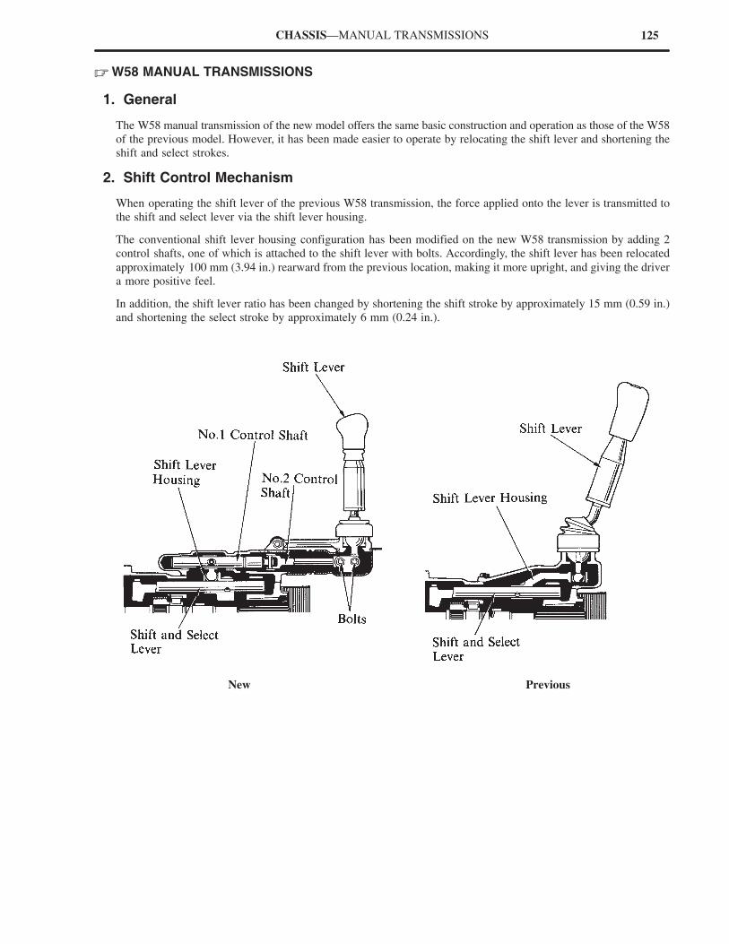
125CHASSIS—MANUAL TRANSMISSIONS
� W58 MANUAL TRANSMISSIONS
1. General
The W58 manual transmission of the new model offers the same basic construction and operation as those of the W58
of the previous model. However, it has been made easier to operate by relocating the shift lever and shortening the
shift and select strokes.
2. Shift Control Mechanism
When operating the shift lever of the previous W58 transmission, the force applied onto the lever is transmitted to
the shift and select lever via the shift lever housing.
The conventional shift lever housing configuration has been modified on the new W58 transmission by adding 2
control shafts, one of which is attached to the shift lever with bolts. Accordingly, the shift lever has been relocated
approximately 100 mm (3.94 in.) rearward from the previous location, making it more upright, and giving the driver
a more positive feel.
In addition, the shift lever ratio has been changed by shortening the shift stroke by approximately 15 mm (0.59 in.)
and shortening the select stroke by approximately 6 mm (0.24 in.).
New Previous
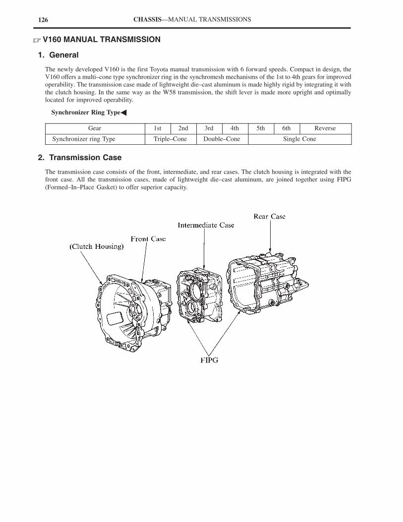
126 CHASSIS—MANUAL TRANSMISSIONS
� V160 MANUAL TRANSMISSION
1. General
The newly developed V160 is the first Toyota manual transmission with 6 forward speeds. Compact in design, the
V160 offers a multi–cone type synchronizer ring in the synchromesh mechanisms of the 1st to 4th gears for improved
operability. The transmission case made of lightweight die–cast aluminum is made highly rigid by integrating it with
the clutch housing. In the same way as the W58 transmission, the shift lever is made more upright and optimally
located for improved operability.
�Synchronizer Ring Type�
Gear 1st 2nd 3rd 4th 5th 6th Reverse
Synchronizer ring Type Triple–Cone Double–Cone Single Cone
2. Transmission Case
The transmission case consists of the front, intermediate, and rear cases. The clutch housing is integrated with the
front case. All the transmission cases, made of lightweight die–cast aluminum, are joined together using FIPG
(Formed–In–Place Gasket) to offer superior capacity.
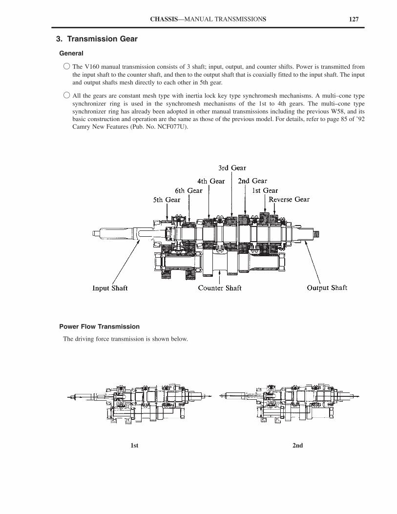
127CHASSIS—MANUAL TRANSMISSIONS
3. Transmission Gear
General
� The V160 manual transmission consists of 3 shaft; input, output, and counter shifts. Power is transmitted from
the input shaft to the counter shaft, and then to the output shaft that is coaxially fitted to the input shaft. The input
and output shafts mesh directly to each other in 5th gear.
� All the gears are constant mesh type with inertia lock key type synchromesh mechanisms. A multi–cone type
synchronizer ring is used in the synchromesh mechanisms of the 1st to 4th gears. The multi–cone type
synchronizer ring has already been adopted in other manual transmissions including the previous W58, and its
basic construction and operation are the same as those of the previous model. For details, refer to page 85 of ’92
Camry New Features (Pub. No. NCF077U).
Power Flow Transmission
The driving force transmission is shown below.
1st 2nd
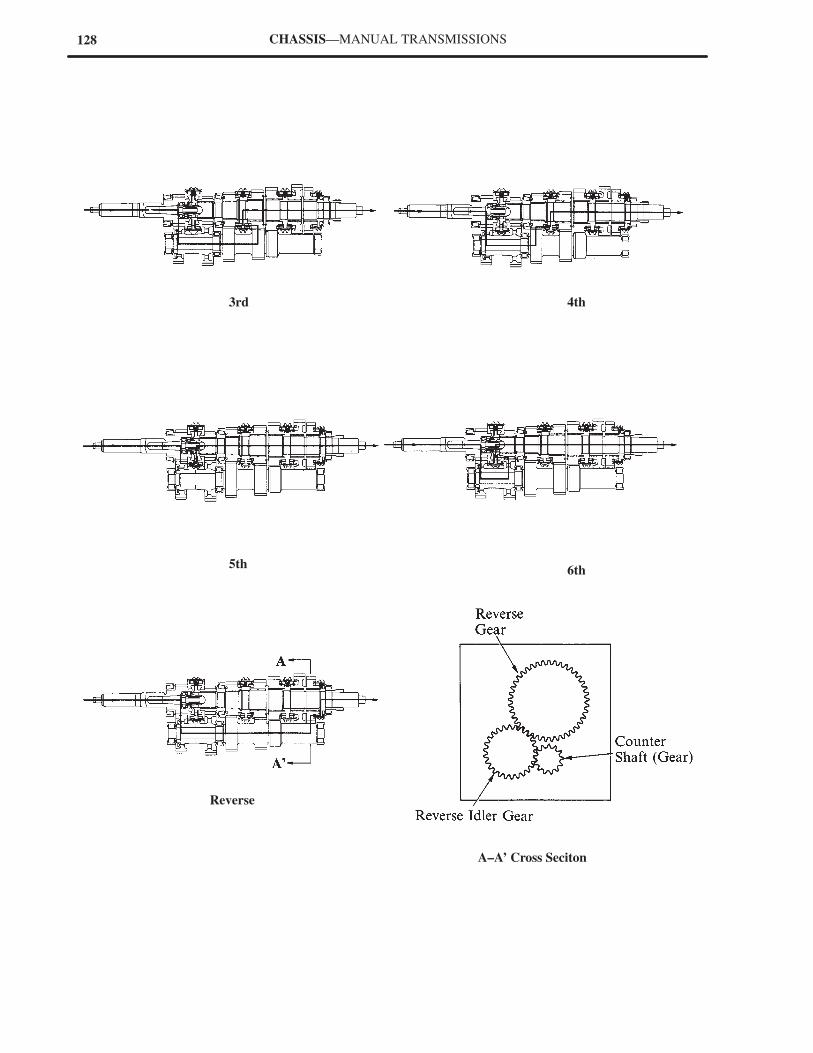
128 CHASSIS—MANUAL TRANSMISSIONS
3rd
Reverse
5th6th
4th
A–A’ Cross Seciton
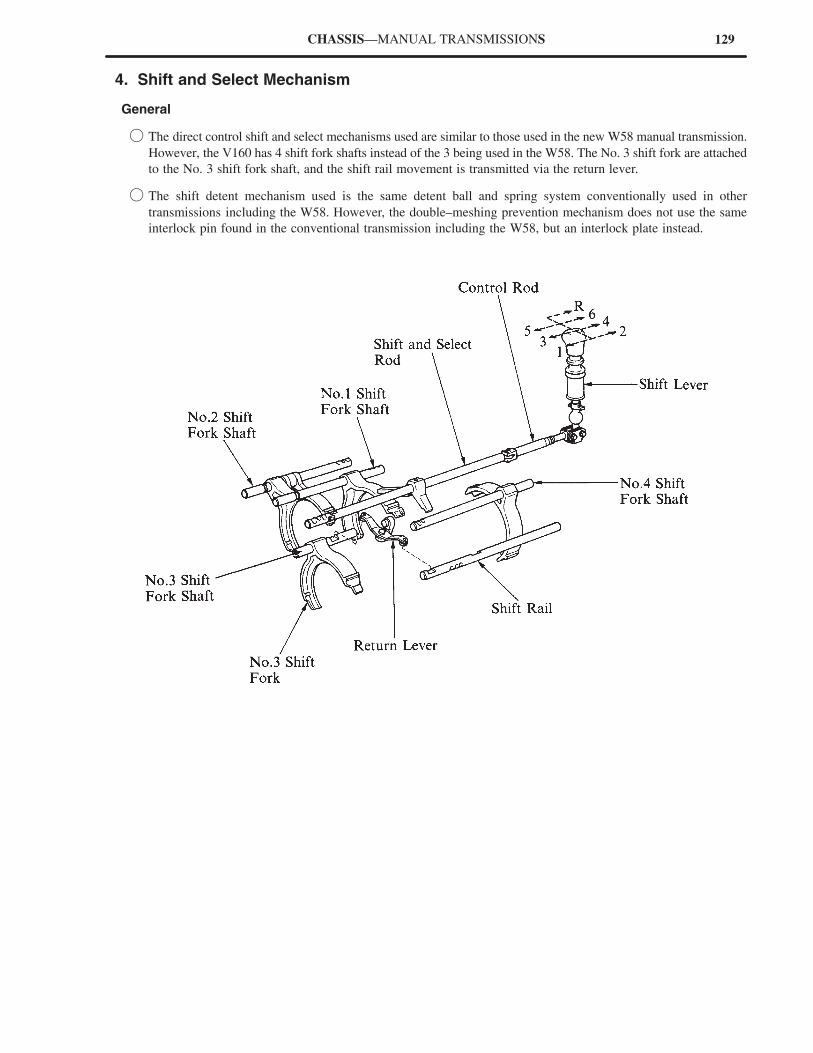
129CHASSIS—MANUAL TRANSMISSIONS
4. Shift and Select Mechanism
General
� The direct control shift and select mechanisms used are similar to those used in the new W58 manual transmission.
However, the V160 has 4 shift fork shafts instead of the 3 being used in the W58. The No. 3 shift fork are attached
to the No. 3 shift fork shaft, and the shift rail movement is transmitted via the return lever.
� The shift detent mechanism used is the same detent ball and spring system conventionally used in other
transmissions including the W58. However, the double–meshing prevention mechanism does not use the same
interlock pin found in the conventional transmission including the W58, but an interlock plate instead.
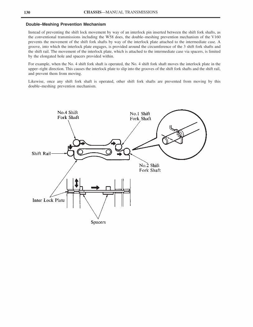
130 CHASSIS—MANUAL TRANSMISSIONS
Double–Meshing Prevention Mechanism
Instead of preventing the shift lock movement by way of an interlock pin inserted between the shift fork shafts, as
the conventional transmissions including the W58 does, the double–meshing prevention mechanism of the V160
prevents the movement of the shift fork shafts by way of the interlock plate attached to the intermediate case. A
groove, into which the interlock plate engages, is provided around the circumference of the 3 shift fork shafts and
the shift rail. The movement of the interlock plate, which is attached to the intermediate case via spacers, is limited
by the elongated hole and spacers provided within.
For example, when the No. 4 shift fork shaft is operated, the No. 4 shift fork shaft moves the interlock plate in the
upper–right direction. This causes the interlock plate to slip into the grooves of the shift fork shafts and the shift rail,
and prevent them from moving.
Likewise, once any shift fork shaft is operated, other shift fork shafts are prevented from moving by this
double–meshing prevention mechanism.
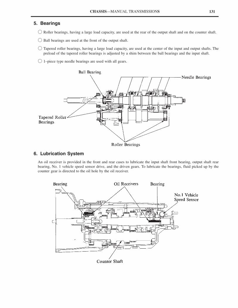
131CHASSIS—MANUAL TRANSMISSIONS
5. Bearings
� Roller bearings, having a large load capacity, are used at the rear of the output shaft and on the counter shaft.
� Ball bearings are used at the front of the output shaft.
� Tapered roller bearings, having a large load capacity, are used at the center of the input and output shafts. The
preload of the tapered roller bearings is adjusted by a shim between the ball bearings and the input shaft.
� 1–piece type needle bearings are used with all gears.
6. Lubrication System
An oil receiver is provided in the front and rear cases to lubricate the input shaft front bearing, output shaft rear
bearing, No. 1 vehicle speed sensor drive, and the driven gears. To lubricate the bearings, fluid picked up by the
counter gear is directed to the oil hole by the oil receiver.
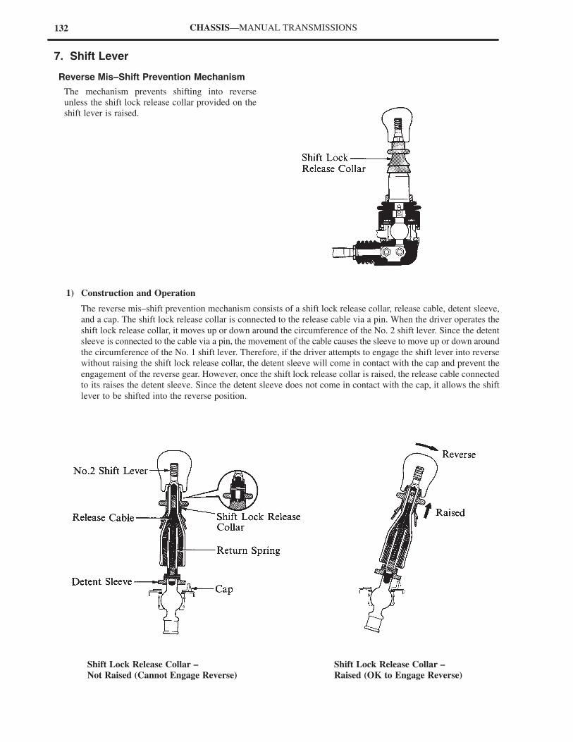
132 CHASSIS—MANUAL TRANSMISSIONS
7. Shift Lever
Reverse Mis–Shift Prevention Mechanism
The mechanism prevents shifting into reverse
unless the shift lock release collar provided on the
shift lever is raised.
1) Construction and Operation
The reverse mis–shift prevention mechanism consists of a shift lock release collar, release cable, detent sleeve,
and a cap. The shift lock release collar is connected to the release cable via a pin. When the driver operates the
shift lock release collar, it moves up or down around the circumference of the No. 2 shift lever. Since the detent
sleeve is connected to the cable via a pin, the movement of the cable causes the sleeve to move up or down around
the circumference of the No. 1 shift lever. Therefore, if the driver attempts to engage the shift lever into reverse
without raising the shift lock release collar, the detent sleeve will come in contact with the cap and prevent the
engagement of the reverse gear. However, once the shift lock release collar is raised, the release cable connected
to its raises the detent sleeve. Since the detent sleeve does not come in contact with the cap, it allows the shift
lever to be shifted into the reverse position.
Shift Lock Release Collar – Shift Lock Release Collar –
Not Raised (Cannot Engage Reverse) Raised (OK to Engage Reverse)

154
When removing and reinstalling the propeller shaft, make sure to inspect the shaft angle at each of
the 3 joints and confirm that they are in the specified range. Refer to the Repair Manual for shaft
angle adjustment.
NOTICE
CHASSIS — PROPELLER SHAFT
PROPELLER SHAFT
� DESCRIPTION
There are 2 separate types of propeller shafts used on the new model, according to the engine model used, either the
2JZ–GE or the 2JZ–GTE.
Both of these propeller shafts are 2–part types, each part consisting of a strong tube offering high centering and
dimensional precision and a small diameter. In addition, the propeller shafts have No. 1, No. 2, and No. 3 joints. The
No. 1 and No. 2 joints are the same Hooke’s universal joint used on the previous model. However, the No. 3 joint
uses a new flexible rubber coupling which is effective in reducing vibration and noise. The No. 1 joint for the 2JZ–GE
engine model connects to the transmission via a sleeve, and the 2JZ–GTE engine model uses a flange.
On both the 2JZ–GE and 2JZ–GTE models, all 3 joints are carefully arranged in such a way that their shaft angles
rest on a straight line. This design ensures a precise driveline linearity from the front of the engine through the
differential to minimize noise and vibration. In addition, the propeller shaft for the 2JZ–GTE incorporates a shaft
length adjustment mechanism for easier removal and reinstallation.
�For 2JZ–GE Engine Model�
�For 2JZ–GTE Engine Model�
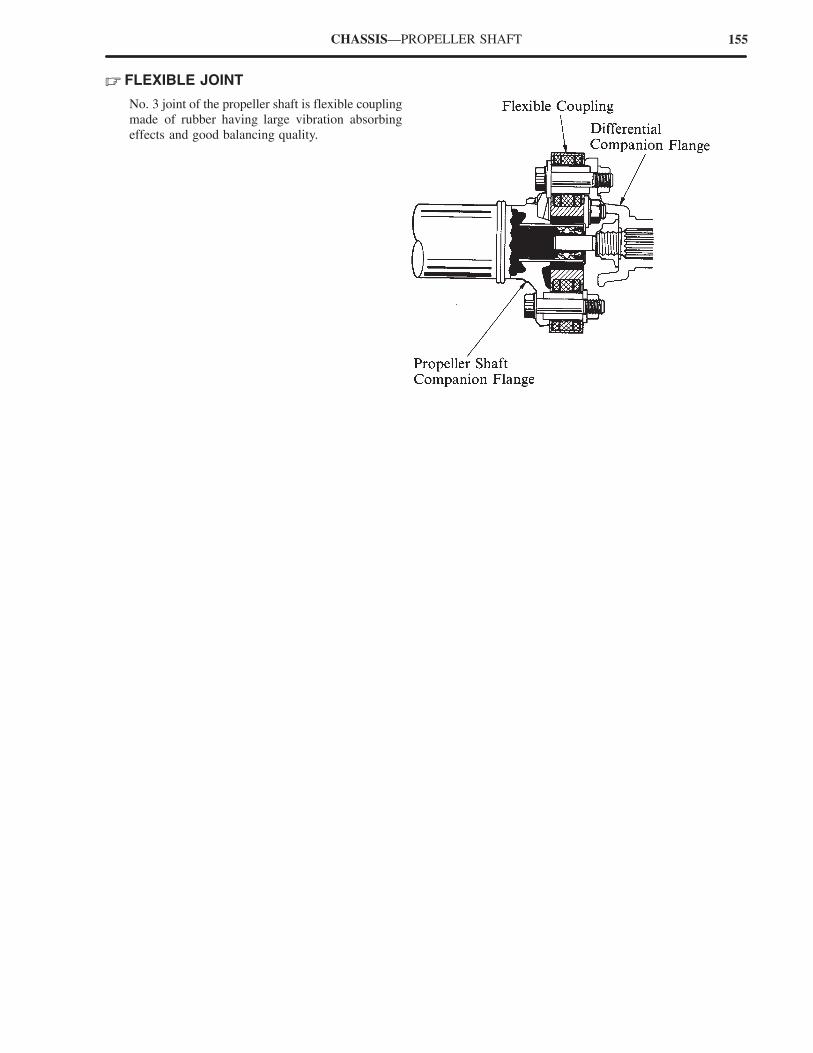
155CHASSIS—PROPELLER SHAFT
� FLEXIBLE JOINT
No. 3 joint of the propeller shaft is flexible coupling
made of rubber having large vibration absorbing
effects and good balancing quality.
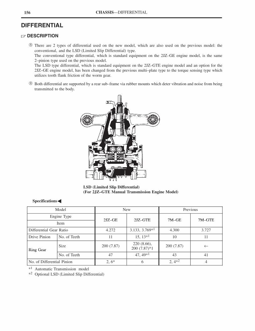
156 CHASSIS—DIFFERENTIAL
DIFFERENTIAL
� DESCRIPTION
� There are 2 types of differential used on the new model, which are also used on the previous model: the
conventional, and the LSD (Limited Slip Differential) type.
The conventional type differential, which is standard equipment on the 2JZ–GE engine model, is the same
2–pinion type used on the previous model.
The LSD type differential, which is standard equipment on the 2JZ–GTE engine model and an option for the
2JZ–GE engine model, has been changed from the previous multi–plate type to the torque sensing type which
utilizes tooth flank friction of the worm gear.
� Both differential are supported by a rear sub–frame via rubber mounts which deter vibration and noise from being
transmitted to the body.
LSD (Limited Slip Differential)
(For 2JZ–GTE Manual Transmission Engine Model)
�Specifications�
Model New Previous
Engine Type2JZ GE 2JZ GTE 7M GE 7M GTE
Item2JZ–GE 2JZ–GTE 7M–GE 7M–GTE
Differential Gear Ratio 4.272 3.133, 3.769*1 4.300 3.727
Drive Pinion No. of Teeth 11 15, 13*1 10 11
Ring GearSize 200 (7.87)
220 (8.66),200 (7.87)*1
200 (7.87) ←Ring Gear
No. of Teeth 47 47, 49*1 43 41
No. of Differential Pinion 2, 6* 6 2, 4*2 4
*1 Automatic Transmission model
*2 Optional LSD (Limited Slip Differential)
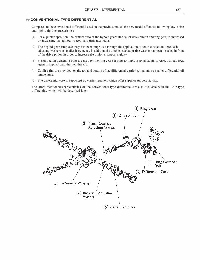
157CHASSIS—DIFFERENTIAL
� CONVENTIONAL TYPE DIFFERENTIAL
Compared to the conventional differential used on the previous model, the new model offers the following low–noise
and highly rigid characteristics:
(1) For a quieter operation, the contact ratio of the hypoid gears (the set of drive pinion and ring gear) is increased
by increasing the number to teeth and their facewidth.
(2) The hypoid gear setup accuracy has been improved through the application of tooth contact and backlash
adjusting washers in smaller increments. In addition, the tooth contact adjusting washer has been installed in front
of the drive pinion in order to increase the pinion’s support rigidity.
(3) Plastic region tightening bolts are used for the ring gear set bolts to improve axial stability. Also, a thread lock
agent is applied onto the bolt threads.
(4) Cooling fins are provided, on the top and bottom of the differential carrier, to maintain a stabler differential oil
temperature.
(5) The differential case is supported by carrier retainers which offer superior support rigidity.
The afore–mentioned characteristics of the conventional type differential are also available with the LSD type
differential, which will be described later.
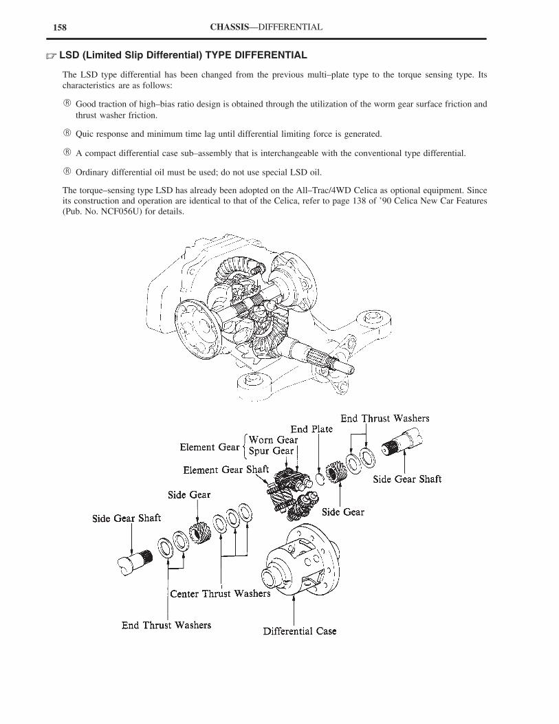
158 CHASSIS—DIFFERENTIAL
� LSD (Limited Slip Differential) TYPE DIFFERENTIAL
The LSD type differential has been changed from the previous multi–plate type to the torque sensing type. Its
characteristics are as follows:
� Good traction of high–bias ratio design is obtained through the utilization of the worm gear surface friction and
thrust washer friction.
� Quic response and minimum time lag until differential limiting force is generated.
� A compact differential case sub–assembly that is interchangeable with the conventional type differential.
� Ordinary differential oil must be used; do not use special LSD oil.
The torque–sensing type LSD has already been adopted on the All–Trac/4WD Celica as optional equipment. Since
its construction and operation are identical to that of the Celica, refer to page 138 of ’90 Celica New Car Features
(Pub. No. NCF056U) for details.
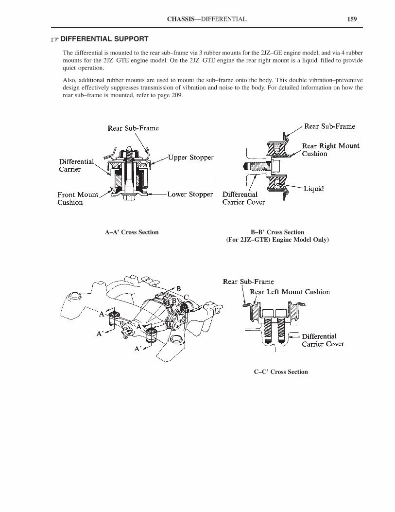
159CHASSIS—DIFFERENTIAL
� DIFFERENTIAL SUPPORT
The differential is mounted to the rear sub–frame via 3 rubber mounts for the 2JZ–GE engine model, and via 4 rubber
mounts for the 2JZ–GTE engine model. On the 2JZ–GTE engine the rear right mount is a liquid–filled to provide
quiet operation.
Also, additional rubber mounts are used to mount the sub–frame onto the body. This double vibration–preventive
design effectively suppresses transmission of vibration and noise to the body. For detailed information on how the
rear sub–frame is mounted, refer to page 209.
A–A’ Cross Section B–B’ Cross Section
(For 2JZ–GTE) Engine Model Only)
C–C’ Cross Section
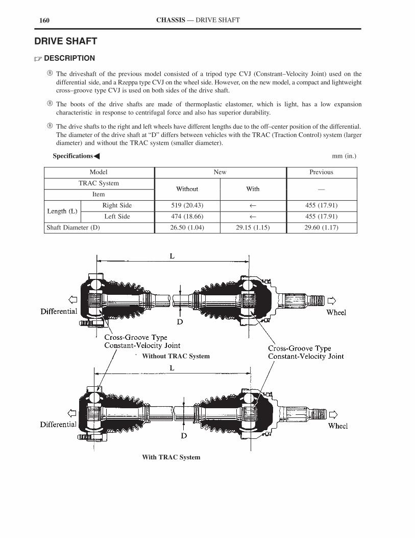
160
Without TRAC System
With TRAC System
CHASSIS — DRIVE SHAFT
DRIVE SHAFT
� DESCRIPTION
� The driveshaft of the previous model consisted of a tripod type CVJ (Constrant–Velocity Joint) used on the
differential side, and a Rzeppa type CVJ on the wheel side. However, on the new model, a compact and lightweight
cross–groove type CVJ is used on both sides of the drive shaft.
� The boots of the drive shafts are made of thermoplastic elastomer, which is light, has a low expansion
characteristic in response to centrifugal force and also has superior durability.
� The drive shafts to the right and left wheels have different lengths due to the off–center position of the differential.
The diameter of the drive shaft at “D” differs between vehicles with the TRAC (Traction Control) system (larger
diameter) and without the TRAC system (smaller diameter).
�Specifications� mm (in.)
Model New Previous
TRAC SystemWithout With
ItemWithout With —
Length (L)Right Side 519 (20.43) ← 455 (17.91)
Length (L)Left Side 474 (18.66) ← 455 (17.91)
Shaft Diameter (D) 26.50 (1.04) 29.15 (1.15) 29.60 (1.17)
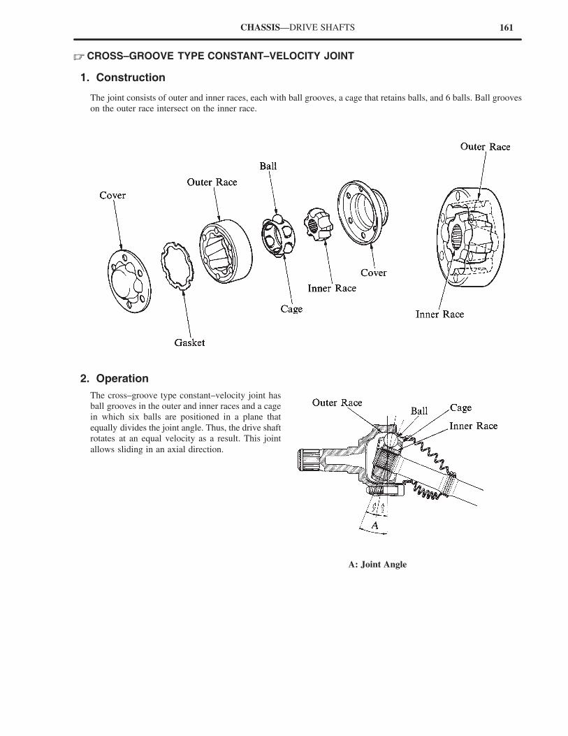
161
A: Joint Angle
CHASSIS—DRIVE SHAFTS
� CROSS–GROOVE TYPE CONSTANT–VELOCITY JOINT
1. Construction
The joint consists of outer and inner races, each with ball grooves, a cage that retains balls, and 6 balls. Ball grooves
on the outer race intersect on the inner race.
2. Operation
The cross–groove type constant–velocity joint has
ball grooves in the outer and inner races and a cage
in which six balls are positioned in a plane that
equally divides the joint angle. Thus, the drive shaft
rotates at an equal velocity as a result. This joint
allows sliding in an axial direction.
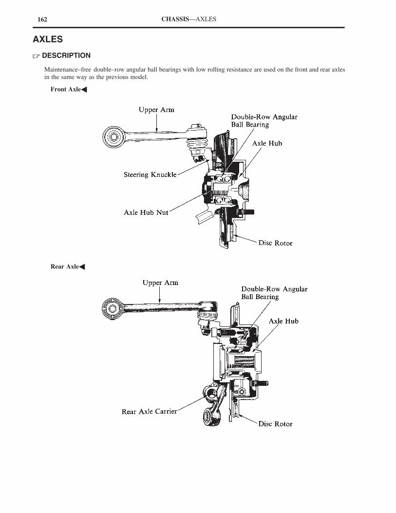
162 CHASSIS—AXLES
AXLES
� DESCRIPTION
Maintenance–free double–row angular ball bearings with low rolling resistance are used on the front and rear axles
in the same way as the previous model.
�Front Axle�
�Rear Axle�
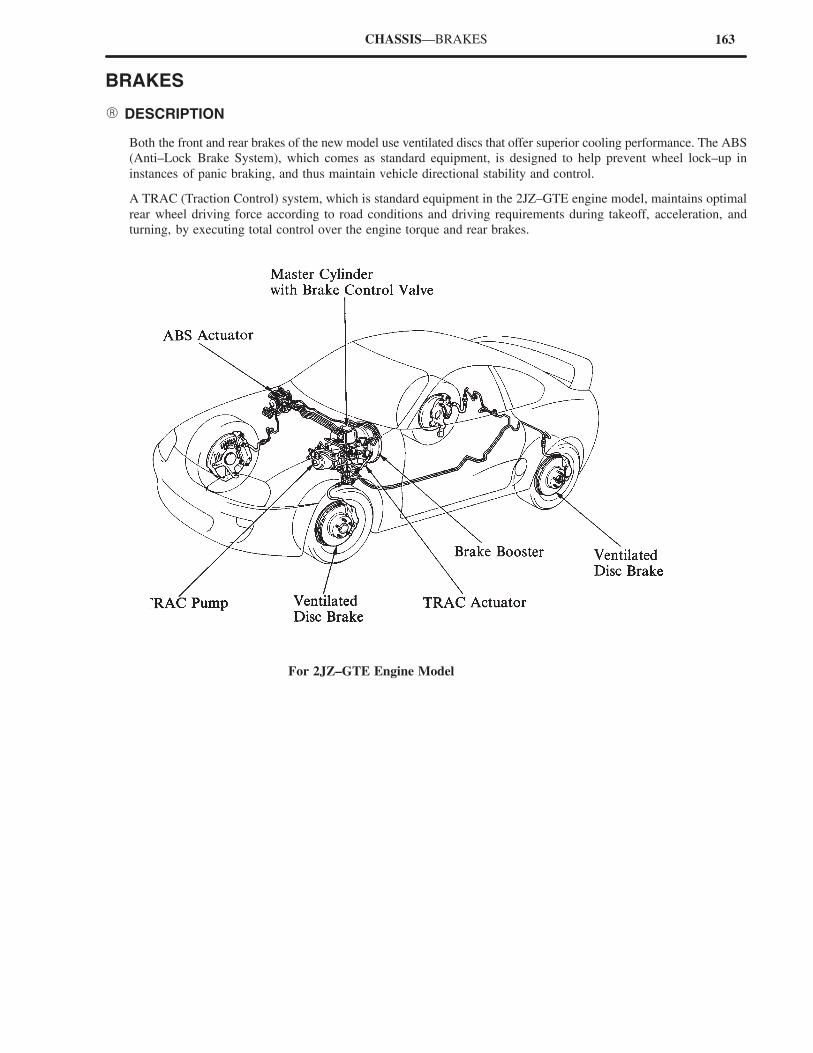
163CHASSIS—BRAKES
BRAKES
� DESCRIPTION
Both the front and rear brakes of the new model use ventilated discs that offer superior cooling performance. The ABS
(Anti–Lock Brake System), which comes as standard equipment, is designed to help prevent wheel lock–up in
instances of panic braking, and thus maintain vehicle directional stability and control.
A TRAC (Traction Control) system, which is standard equipment in the 2JZ–GTE engine model, maintains optimal
rear wheel driving force according to road conditions and driving requirements during takeoff, acceleration, and
turning, by executing total control over the engine torque and rear brakes.
For 2JZ–GTE Engine Model
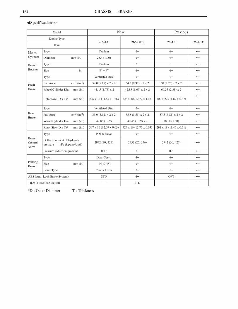
164 CHASSIS — BRAKES
�Specifications�
Model New Previous
Engine Type2JZ GE 2JZ GTE 7M GE 7M GTE
Item2JZ–GE 2JZ–GTE 7M–GE 7M–GTE
Master Type Tandem ← ← ←Master
Cylinder Diameter mm (in.) 25.4 (1.00) ← ← ←
Brake Type Tandem ← ← ←Brake
Booster Size in. 8” + 9” ← ← ←
Type Ventilated Disc ← ← ←
FrontPad Area cm2 (in.2) 59.0 (9.15) x 2 x 2 64.3 (9.97) x 2 x 2 50 (7.75) x 2 x 2 ←
Front
Brake Wheel Cylinder Dia. mm (in.) 44.45 (1.75) x 2 42.85 (1.69) x 2 x 2 60.33 (2.38) x 2 ←
Rotor Size (D x T)* mm (in.) 296 x 32 (11.65 x 1.26) 323 x 30 (12.72 x 1.18) 302 x 22 (11.89 x 0.87)←
Type Ventilated Disc ← ← ←
Rear
BrakePad Area cm2 (in.2) 33.0 (5.12) x 2 x 2 35.8 (5.55) x 2 x 2 37.5 (5.81) x 2 x 2 ←
Brake
Wheel Cylinder Dia. mm (in.) 42.86 (1.69) 40.45 (1.59) x 2 38.10 (1.50) ←
Rotor Size (D x T)* mm (in.) 307 x 16 (12.09 x 0.63) 324 x 16 (12.76 x 0.63) 291 x 18 (11.46 x 0.71) ←
Type P & B Valve ← ← ←
Brake
Control
Valve
Deflection point of hydraulic
pressure kPa (kg/cm2;; psi)2942 (30; 427) 2452 (25, 356) 2942 (30, 427) ←
Valve
Pressure reduction gradient 0.37 ← 0.6 ←
Type Dual–Servo ← ← ←
Parking
BrakeSize mm (in.) 190 (7.48) ← ← ←
Brake
Lever Type Center Lever ← ← ←
ABS (Anti–Lock Brake System) STD ← OPT ←
TRAC (Traction Control) — STD — —
*D : Outer Diameter T : Thickness
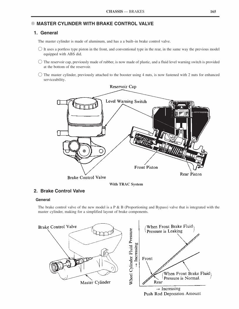
165CHASSIS — BRAKES
� MASTER CYLINDER WITH BRAKE CONTROL VALVE
1. General
The master cylinder is made of aluminum, and has a a built–in brake control valve.
� It uses a portless type piston in the front, and conventional type in the rear, in the same way the previous model
equipped with ABS did.
� The reservoir cap, previously made of rubber, is now made of plastic, and a fluid level warning switch is provided
at the bottom of the reservoir.
� The master cylinder, previously attached to the booster using 4 nuts, is now fastened with 2 nuts for enhanced
serviceability.
With TRAC System
2. Brake Control Valve
General
The brake control valve of the new model is a P & B (Proportioning and Bypass) valve that is integrated with the
master cylinder, making for a simplified layout of brake components.
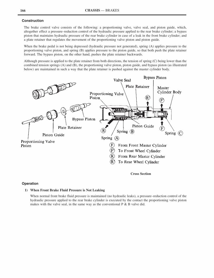
166 CHASSIS — BRAKES
Construction
The brake control valve consists of the following: a proportioning valve, valve seal, and piston guide, which,
altogether effect a pressure–reduction control of the hydraulic pressure applied to the rear brake cylinder; a bypass
piston that maintains hydraulic pressure of the rear brake cylinder in case of a leak in the front brake cylinder; and
a plate retainer that regulates the movement of the proportioning valve piston and piston guide.
When the brake pedal is not being depressed (hydraulic pressure not generated), spring (A) applies pressure to the
proportioning valve piston, and spring (B) applies pressure to the piston guide, so that both push the plate retainer
forward. The bypass piston, on the other hand, pushes the plate retainer backwards.
Although pressure is applied to the plate retainer from both directions, the tension of spring (C) being lower than the
combined tension springs (A) and (B), the proportioning valve piston, piston guide, and bypass piston (as illustrated
below) are maintained in such a way that the plate retainer is pushed against the master cylinder body.
Cross Section
Operation
1) When Front Brake Fluid Pressure is Not Leaking
When normal front brake fluid pressure is maintained (no hydraulic leaks), a pressure–reduction control of the
hydraulic pressure applied to the rear brake cylinder is executed by the contact the proportioning valve piston
makes with the valve seal, in the same way as the conventional P & B valve did.
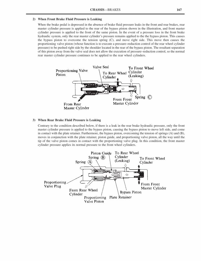
167CHASSIS—BRAKES
2) When Front Brake Fluid Pressure is Leaking
When the brake pedal is depressed in the absence of brake fluid pressure leaks in the front and rear brakes, rear
master cylinder pressure is applied to the rear of the bypass piston shown in the illustration, and front master
cylinder pressure is applied to the front of the same piston. In the event of a pressure loss in the front brake
hydraulic system, only the rear master cylinder’s pressure remains applied to the the bypass piston. This causes
the bypass piston to overcome the tension spring (C), and move right side. This move then causes the
proportioning valve piston (whose function is to execute a pressure–reduction control of the rear wheel cylinder
pressure) to be pushed right side by the shoulder located in the rear of the bypass piston. The resultant separation
of this piston away from the valve seal does not allow the execution of pressure–reduction control, so the normal
rear master cylinder pressure continues to be applied to the rear wheel cylinders.
3) When Rear Brake Fluid Pressure is Leaking
Contrary to the condition described below, if there is a leak in the rear brake hydraulic pressure, only the front
master cylinder pressure is applied to the bypass piston, causing the bypass piston to move left side, and come
in contact with the plate retainer. Furthermore, the bypass piston, overcoming the tension of springs (A) and (B),
moves in conjunction with the plate retainer, piston guide, and proportioning valve piston, all the way until the
tip of the valve piston comes in contact with the proportioning valve plug. In this condition, the front master
cylinder pressure applies its normal pressure to the front wheel cylinders.
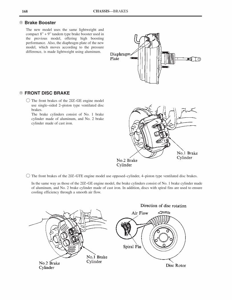
168 CHASSIS—BRAKES
� Brake Booster
The new model uses the same lightweight and
compact 8” + 9” tandem type brake booster used in
the previous model, offering high boosting
performance. Also, the diaphragm plate of the new
model, which moves according to the pressure
difference, is made lightweight using aluminum.
� FRONT DISC BRAKE
� The front brakes of the 2JZ–GE engine model
use single–sided 2–piston type ventilated disc
brakes.
The brake cylinders consist of No. 1 brake
cylinder made of aluminum, and No. 2 brake
cylinder made of cast iron.
� The front brakes of the 2JZ–GTE engine model use opposed–cylinder, 4–piston type ventilated disc brakes.
In the same way as those of the 2JZ–GE engine model, the brake cylinders consist of No. 1 brake cylinder made
of aluminum, and No. 2 brake cylinder made of cast iron. In addition, discs with spiral fins are used to ensure
cooling efficiency through a smooth air flow.
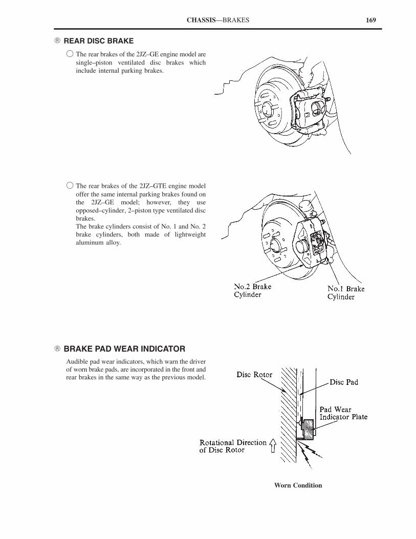
169
Worn Condition
CHASSIS—BRAKES
� REAR DISC BRAKE
� The rear brakes of the 2JZ–GE engine model are
single–piston ventilated disc brakes which
include internal parking brakes.
� The rear brakes of the 2JZ–GTE engine model
offer the same internal parking brakes found on
the 2JZ–GE model; however, they use
opposed–cylinder, 2–piston type ventilated disc
brakes.
The brake cylinders consist of No. 1 and No. 2
brake cylinders, both made of lightweight
aluminum alloy.
� BRAKE PAD WEAR INDICATOR
Audible pad wear indicators, which warn the driver
of worn brake pads, are incorporated in the front and
rear brakes in the same way as the previous model.
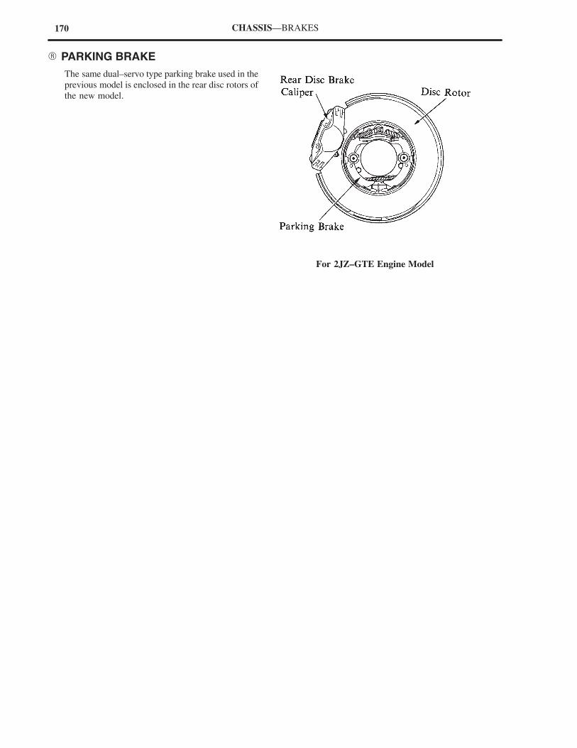
170
For 2JZ–GTE Engine Model
CHASSIS—BRAKES
� PARKING BRAKE
The same dual–servo type parking brake used in the
previous model is enclosed in the rear disc rotors of
the new model.
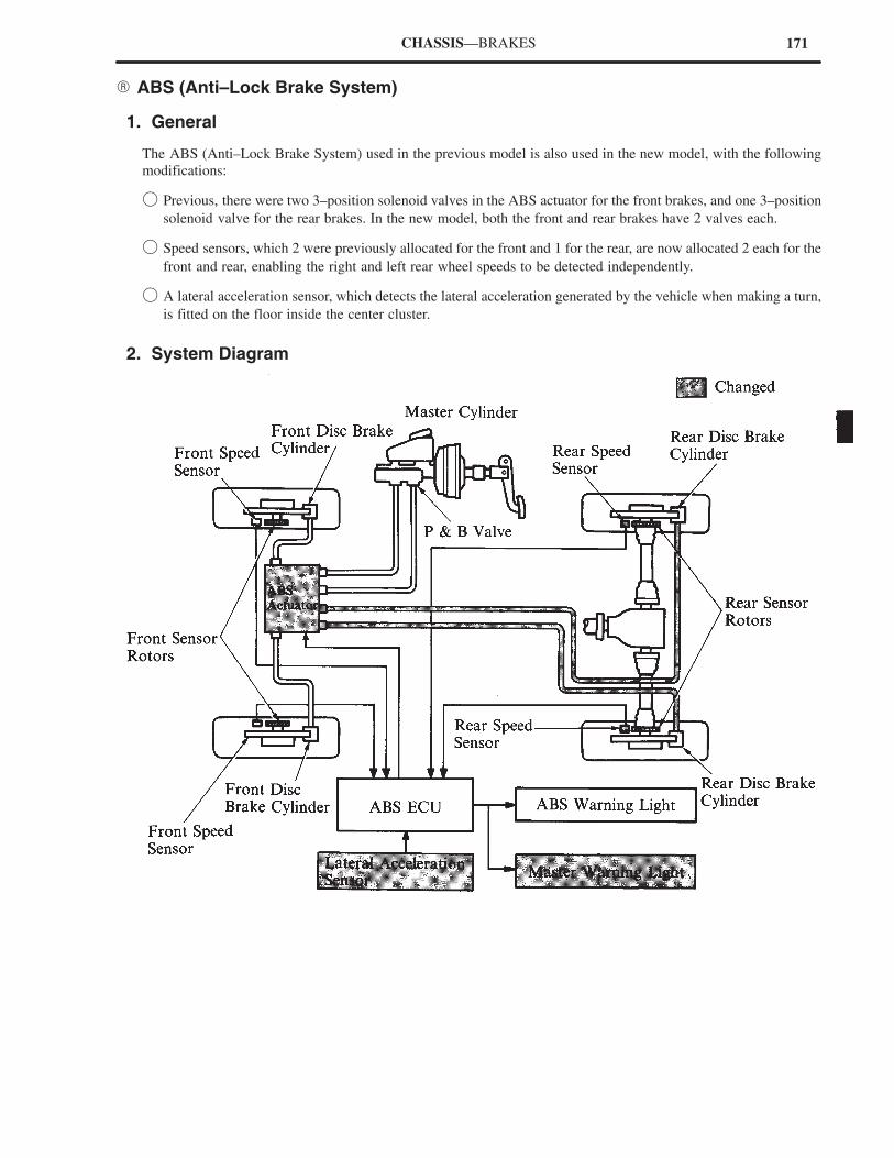
171CHASSIS—BRAKES
� ABS (Anti–Lock Brake System)
1. General
The ABS (Anti–Lock Brake System) used in the previous model is also used in the new model, with the following
modifications:
� Previous, there were two 3–position solenoid valves in the ABS actuator for the front brakes, and one 3–position
solenoid valve for the rear brakes. In the new model, both the front and rear brakes have 2 valves each.
� Speed sensors, which 2 were previously allocated for the front and 1 for the rear, are now allocated 2 each for the
front and rear, enabling the right and left rear wheel speeds to be detected independently.
� A lateral acceleration sensor, which detects the lateral acceleration generated by the vehicle when making a turn,
is fitted on the floor inside the center cluster.
2. System Diagram
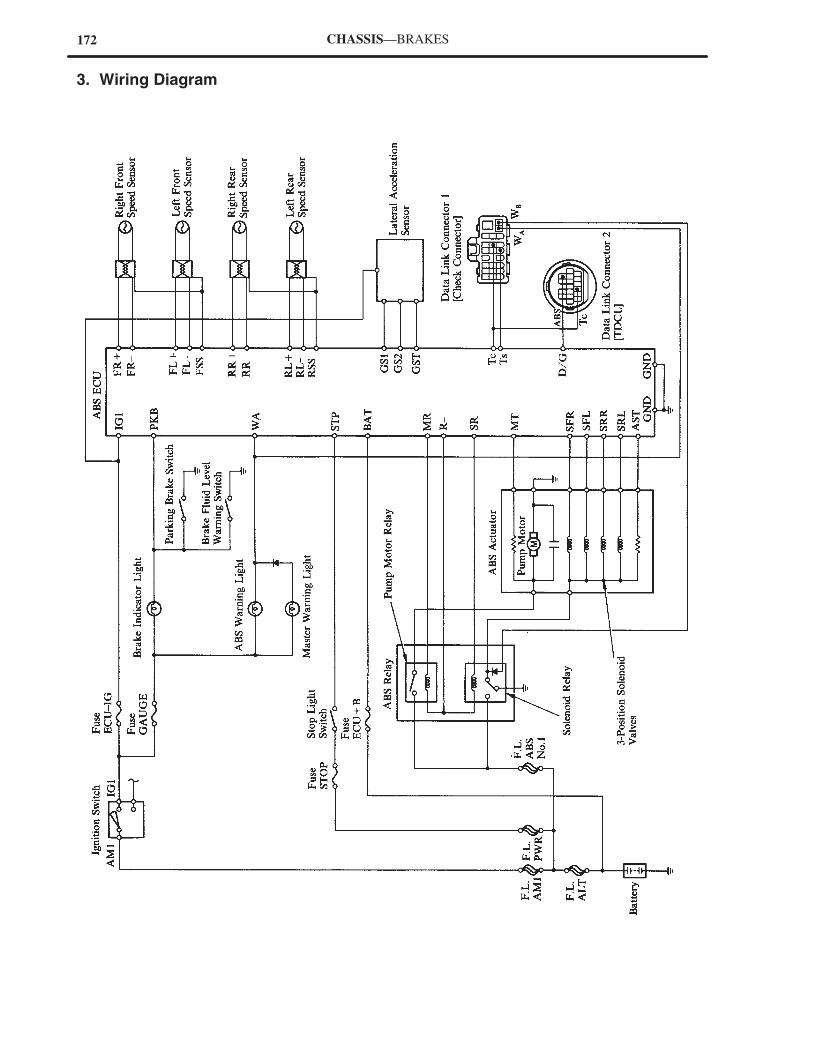
172 CHASSIS—BRAKES
3. Wiring Diagram
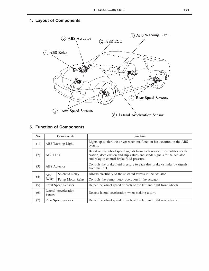
173CHASSIS—BRAKES
4. Layout of Components
5. Function of Components
No. Components Function
(1) ABS Warning LightLights up to alert the driver when malfunction has occurred in the ABSsystem.
(2) ABS ECUBased on the wheel speed signals from each sensor, it calculates accel-eration, deceleration and slip values and sends signals to the actuatorand relay to control brake fluid pressure.
(3) ABS ActuatorControls the brake fluid pressure to each disc brake cylinder by signalsfrom the ECU.
(4)ABS Solenoid Relay Directs electricity to the solenoid valves in the actuator.
(4)ABSRelay Pump Motor Relay Controls the pump motor operation in the actuator.
(5) Front Speed Sensors Detect the wheel speed of each of the left and right front wheels.
(6)Lateral AccelerationSensor
Detects lateral acceleration when making a turn.
(7) Rear Speed Sensors Detect the wheel speed of each of the left and right rear wheels.
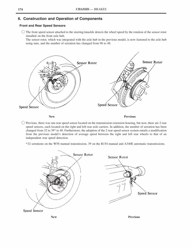
174 CHASSIS — BRAKES
6. Construction and Operation of Components
Front and Rear Speed Sensors
� The front speed sensor attached to the steering knuckle detects the wheel speed by the rotation of the sensor rotor
installed on the front axle hub.
The sensor rotor, which was integrated with the axle hub in the previous model, is now fastened to the axle hub
using nuts, and the number of serration has changed from 96 to 48.
New Previous
� Previous, there was one rear speed sensor located on the transmission extension housing, but now, there are 2 rear
speed sensors, each located on the right and left rear axle carriers. In addition, the number of serration has been
changed from 32 to 39* to 48. Furthermore, the adoption of the 2 rear speed sensor system entails a modification
from the previous model’s detection of average speed between the right and left rear wheels to that of an
independent rear speed detection.
*32 serrations on the W58 manual transmission, 39 on the R154 manual and A340E automatic transmissions.
New Previous
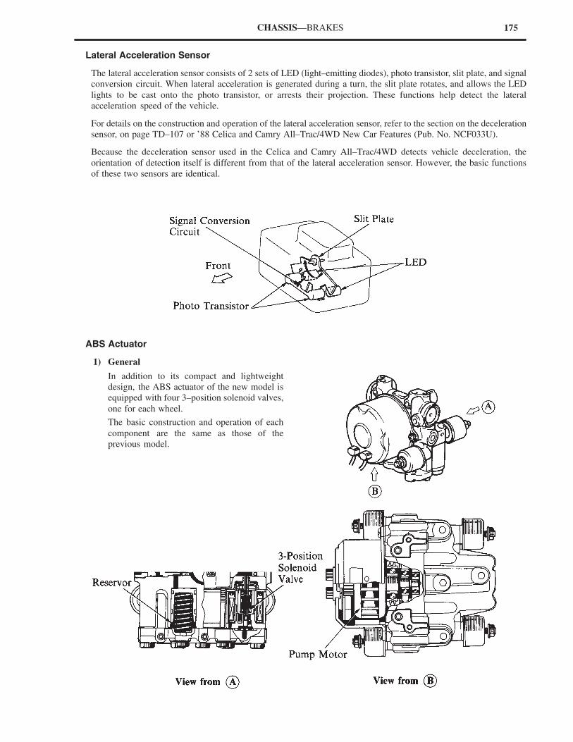
175CHASSIS—BRAKES
Lateral Acceleration Sensor
The lateral acceleration sensor consists of 2 sets of LED (light–emitting diodes), photo transistor, slit plate, and signal
conversion circuit. When lateral acceleration is generated during a turn, the slit plate rotates, and allows the LED
lights to be cast onto the photo transistor, or arrests their projection. These functions help detect the lateral
acceleration speed of the vehicle.
For details on the construction and operation of the lateral acceleration sensor, refer to the section on the deceleration
sensor, on page TD–107 or ’88 Celica and Camry All–Trac/4WD New Car Features (Pub. No. NCF033U).
Because the deceleration sensor used in the Celica and Camry All–Trac/4WD detects vehicle deceleration, the
orientation of detection itself is different from that of the lateral acceleration sensor. However, the basic functions
of these two sensors are identical.
ABS Actuator
1) General
In addition to its compact and lightweight
design, the ABS actuator of the new model is
equipped with four 3–position solenoid valves,
one for each wheel.
The basic construction and operation of each
component are the same as those of the
previous model.
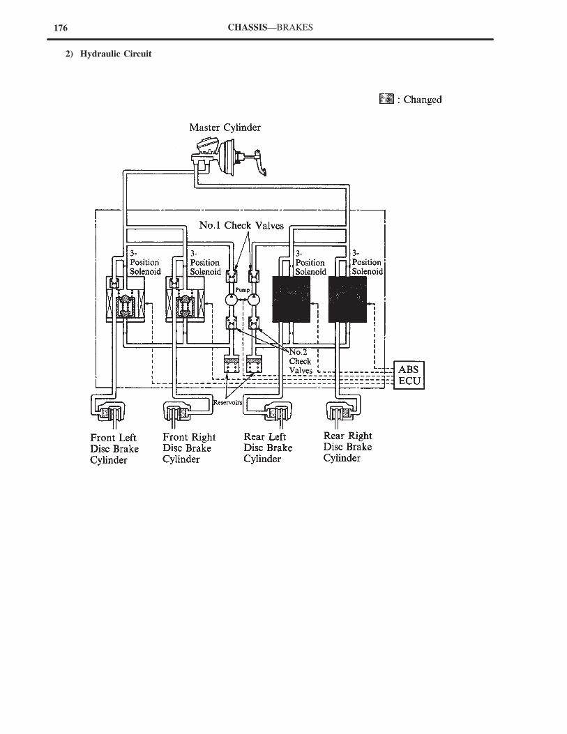
176 CHASSIS—BRAKES
2) Hydraulic Circuit
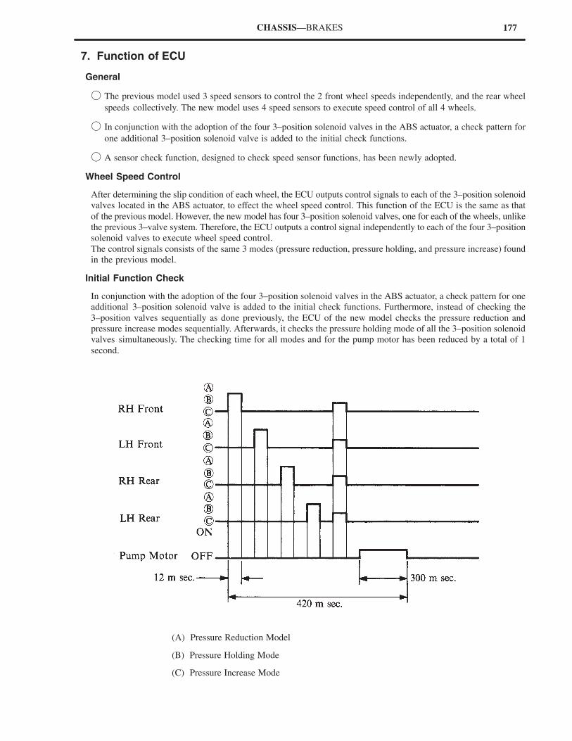
177CHASSIS—BRAKES
7. Function of ECU
General
� The previous model used 3 speed sensors to control the 2 front wheel speeds independently, and the rear wheel
speeds collectively. The new model uses 4 speed sensors to execute speed control of all 4 wheels.
� In conjunction with the adoption of the four 3–position solenoid valves in the ABS actuator, a check pattern for
one additional 3–position solenoid valve is added to the initial check functions.
� A sensor check function, designed to check speed sensor functions, has been newly adopted.
Wheel Speed Control
After determining the slip condition of each wheel, the ECU outputs control signals to each of the 3–position solenoid
valves located in the ABS actuator, to effect the wheel speed control. This function of the ECU is the same as that
of the previous model. However, the new model has four 3–position solenoid valves, one for each of the wheels, unlike
the previous 3–valve system. Therefore, the ECU outputs a control signal independently to each of the four 3–position
solenoid valves to execute wheel speed control.
The control signals consists of the same 3 modes (pressure reduction, pressure holding, and pressure increase) found
in the previous model.
Initial Function Check
In conjunction with the adoption of the four 3–position solenoid valves in the ABS actuator, a check pattern for one
additional 3–position solenoid valve is added to the initial check functions. Furthermore, instead of checking the
3–position valves sequentially as done previously, the ECU of the new model checks the pressure reduction and
pressure increase modes sequentially. Afterwards, it checks the pressure holding mode of all the 3–position solenoid
valves simultaneously. The checking time for all modes and for the pump motor has been reduced by a total of 1
second.
(A) Pressure Reduction Model
(B) Pressure Holding Mode
(C) Pressure Increase Mode
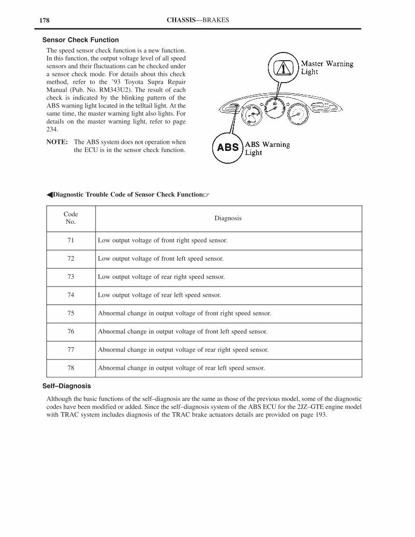
178 CHASSIS—BRAKES
Sensor Check Function
The speed sensor check function is a new function.
In this function, the output voltage level of all speed
sensors and their fluctuations can be checked under
a sensor check mode. For details about this check
method, refer to the ’93 Toyota Supra Repair
Manual (Pub. No. RM343U2). The result of each
check is indicated by the blinking pattern of the
ABS warning light located in the telltail light. At the
same time, the master warning light also lights. For
details on the master warning light, refer to page
234.
NOTE: The ABS system does not operation when
the ECU is in the sensor check function.
�Diagnostic Trouble Code of Sensor Check Function�
CodeNo.
Diagnosis
71 Low output voltage of front right speed sensor.
72 Low output voltage of front left speed sensor.
73 Low output voltage of rear right speed sensor.
74 Low output voltage of rear left speed sensor.
75 Abnormal change in output voltage of front right speed sensor.
76 Abnormal change in output voltage of front left speed sensor.
77 Abnormal change in output voltage of rear right speed sensor.
78 Abnormal change in output voltage of rear left speed sensor.
Self–Diagnosis
Although the basic functions of the self–diagnosis are the same as those of the previous model, some of the diagnostic
codes have been modified or added. Since the self–diagnosis system of the ABS ECU for the 2JZ–GTE engine model
with TRAC system includes diagnosis of the TRAC brake actuators details are provided on page 193.
179CHASSIS—BRAKES
�Diagnostic Trouble Codes of Self Diagnosis (Excluding the 2JZ–GTE Engine Model)�
Code NoModel
DiagnosisCode No.New Previous
Diagnosis
11 Open circuit in solenoid relay circuit.
12 Short circuit in solenoid relay circuit.
13 Open circuit in pump motor relay circuit.
14 Short circuit in pump motor relay circuit.
21 Open or short circuit in 3–position solenoid of front right wheel.
22 Open or short circuit in 3–position solenoid of front left wheel.
23 — Open or short circuit in 3–position solenoid of rear right wheel.
23— Open or short circuit in 3–position solenoid of rear wheel.
24 — Open or short circuit in solenoid valve of rear left wheel.
31 Front right wheel speed sensor signal malfunction.
32 Front left wheel speed sensor signal malfunction.
33 — Rear right wheel speed sensor signal malfunction.
33— Rear wheel speed sensor signal malfunction.
34 — Rear left wheel speed sensor signal malfunction.
35 — Open circuit in front left or rear right speed sensors.
36 — Open circuit in front right or rear left speed sensors.
41 —
Low battery voltage (9.5 V or lower) or abnormally highbattery voltage (17 V or higher).41
— Low battery voltage (9.5 V or lower).
42 — Abnormally high voltage (17 V or higher).
44 — Lateral acceleration sensor signal malfunction.
51 Pump motor locked or open circuit.
Always ON Malfunction in ABS ECU.
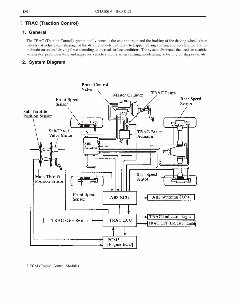
180 CHASSIS—BRAKES
� TRAC (Traction Control)
1. General
The TRAC (Traction Control) system totally controls the engine torque and the braking of the driving wheels (rear
wheels), it helps avoid slippage of the driving wheels that tends to happen during starting and acceleration and to
maintain an optimal driving force according to the road surface conditions. The system eliminates the need for a subtle
accelerator pedal operation and improves vehicle stability when starting, accelerating or turning on slippery roads.
2. System Diagram
* ECM (Engine Control Module)
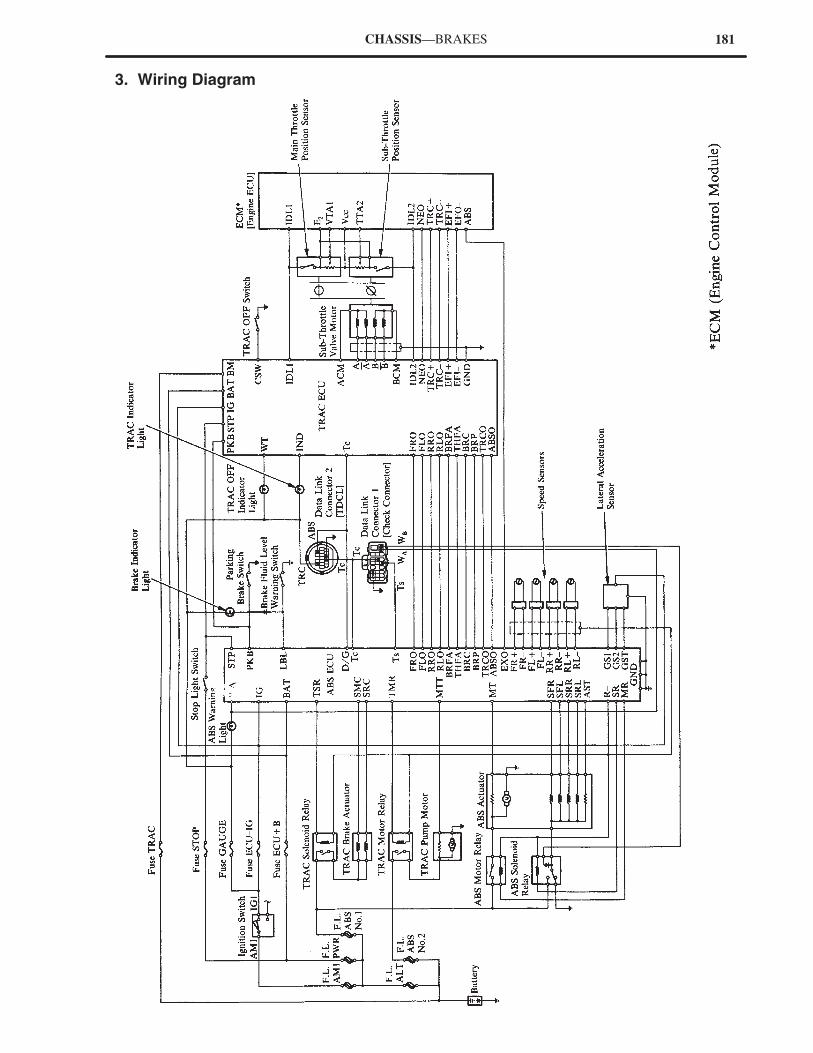
181CHASSIS—BRAKES
3. Wiring Diagram
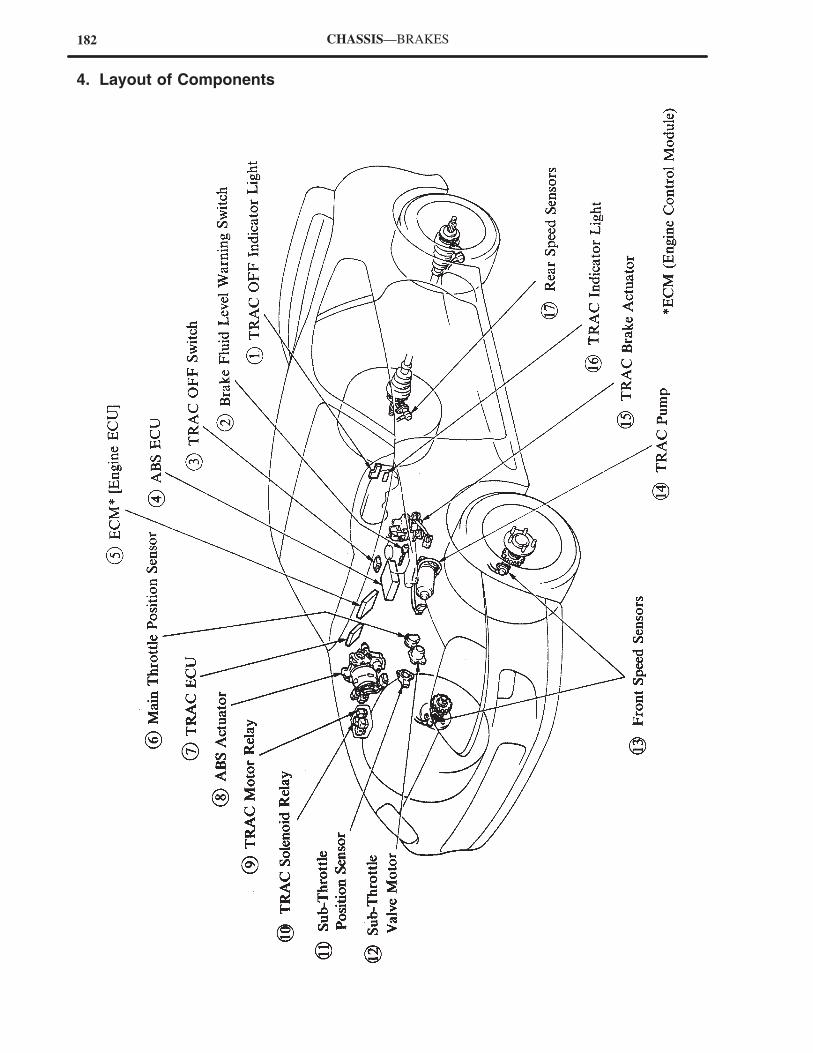
182 CHASSIS—BRAKES
4. Layout of Components
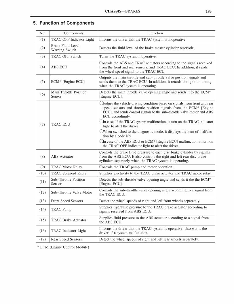
183CHASSIS—BRAKES
5. Function of Components
No. Components Function
(1) TRAC OFF Indicator Light Informs the driver that the TRAC system is inoperative.
(2)Brake Fluid LevelWarning Switch
Detects the fluid level of the brake master cylinder reservoir.
(3) TRAC OFF Switch Turns the TRAC system inoperative.
(4) ABS ECUControls the ABS and TRAC actuators according to the signals receivedfrom the front and rear sensors and TRAC ECU In addition it sends(4) ABS ECU from the front and rear sensors, and TRAC ECU. In addition, it sendsthe wheel speed signal to the TRAC ECU.
(5) ECM* [Engine ECU]Outputs the main throttle and sub–throttle valve position signals andsends them to the TRAC ECU. In addition, it retards the ignition timingwhen the TRAC system is operating.
(6)Main Throttle Position Sensor
Detects the main throttle valve opening angle and sends it to the ECM*[Engine ECU].
(7) TRAC ECU
�Judges the vehicle driving condition based on signals from front and rear
speed sensors and throttle position signals from the ECM* [EngineECU], and sends control signals to the sub–throttle valve motor and ABSECU accordingly.
�In case of the TRAC system malfunction, it turn on the TRAC indicator
light to alert the driver.
�When switched to the diagnostic mode, it displays the item of malfunc-
tion by a code No.
�In case of the ABS ECU or ECM* [Engine ECU] malfunction, it turn on
the TRAC OFF indicator light to alert the driver.
(8) ABS ActuatorControls the brake fluid pressure to each disc brake cylinder by signalsfrom the ABS ECU. It also controls the right and left rear disc brakecylinders separately when the TRAC system is operating.
(9) TRAC Motor Relay Controls the TRAC pump and motor operation.
(10) TRAC Solenoid Relay Supplies electricity to the TRAC brake actuator and TRAC motor relay.
(11)Sub–Throttle Position Sensor
Detects the sub–throttle valve opening angle and sends it the the ECM*[Engine ECU].
(12) Sub–Throttle Valve MotorControls the sub–throttle valve opening angle according to a signal fromthe TRAC ECU.
(13) Front Speed Sensors Detect the wheel speeds of right and left front wheels separately.
(14) TRAC PumpSupplies hydraulic pressure to the TRAC brake actuator according tosignals received from ABS ECU.
(15) TRAC Brake ActuatorSupplies fluid pressure to the ABS actuator according to a signal fromthe ABS ECU.
(16) TRAC Indicator LightInforms the driver that the TRAC system is operative; also warns thedriver of a system malfunction.
(17) Rear Speed Sensors Detect the wheel speeds of right and left rear wheels separately.
* ECM (Engine Control Module)
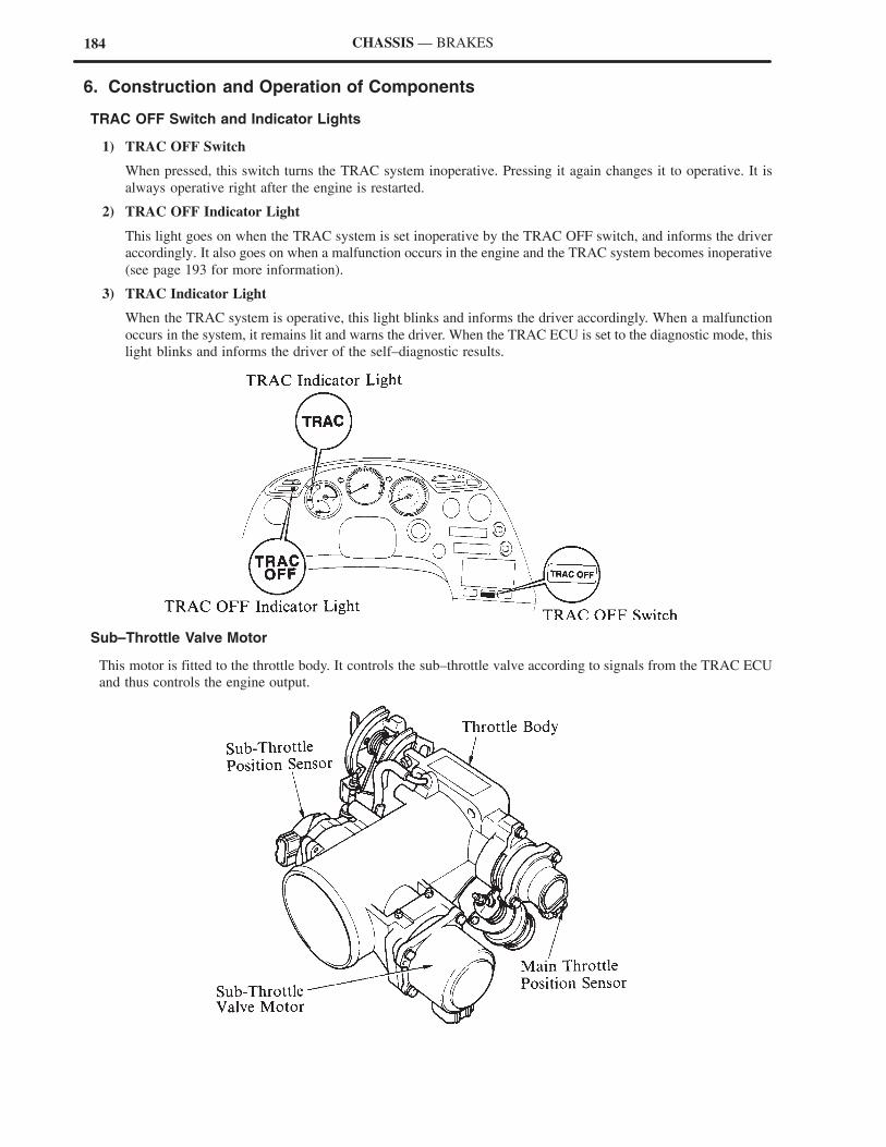
184 CHASSIS — BRAKES
6. Construction and Operation of Components
TRAC OFF Switch and Indicator Lights
1) TRAC OFF Switch
When pressed, this switch turns the TRAC system inoperative. Pressing it again changes it to operative. It is
always operative right after the engine is restarted.
2) TRAC OFF Indicator Light
This light goes on when the TRAC system is set inoperative by the TRAC OFF switch, and informs the driver
accordingly. It also goes on when a malfunction occurs in the engine and the TRAC system becomes inoperative
(see page 193 for more information).
3) TRAC Indicator Light
When the TRAC system is operative, this light blinks and informs the driver accordingly. When a malfunction
occurs in the system, it remains lit and warns the driver. When the TRAC ECU is set to the diagnostic mode, this
light blinks and informs the driver of the self–diagnostic results.
Sub–Throttle Valve Motor
This motor is fitted to the throttle body. It controls the sub–throttle valve according to signals from the TRAC ECU
and thus controls the engine output.
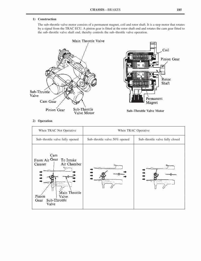
185CHASSIS—BRAKES
1) Construction
The sub–throttle valve motor consists of a permanent magnet, coil and rotor shaft. It is a step motor that rotates
by a signal from the TRAC ECU. A pinion gear is fitted at the rotor shaft end and rotates the cam gear fitted to
the sub–throttle valve shaft end, thereby controls the sub–throttle valve operation.
Sub–Throttle Valve Motor
2) Operation
When TRAC Not Operative When TRAC Operative
Sub–throttle valve fully opened Sub–throttle valve 50% opened Sub–throttle valve fully closed

186 CHASSIS—BRAKES
Sub–throttle Position Sensor
This sensor is fitted to the sub–throttle valve shaft.
It converts the sub–throttle valve opening angle to
a voltage signal and sends the signal to the TRAC
ECU via the ECM* [Engine ECU].
The sub–throttle position sensor is built and
operates in the same way as the main throttle valve.
*ECM (Engine Control Module)
TRAC Pump
The function of the TRAC pump is to generate brake fluid pressure necessary for applying pressure to the disc brake
cylinders when the TRAC system is operating. It picks up the brake fluid from the master cylinder reservoir, applies
pressure to it, and directs it to the TRAC brake actuator. It is a motor–driven, 3–cylinder radial pump.
A–A’ Cross Section

187CHASSIS—BRAKES
TRAC Brake Actuator
1) General
The TRAC brake actuator regulates the brake fluid pressure in the disc brake cylinders of the right and left rear
wheels separately via the ABS actuator according to signals from the ABS ECU, controlling the rear wheels.
The TRAC brake actuator consists of the following 5 components:
Components Function
Master Cylinder CutSolenoid Valve
Opens and closes the fluid circuit from the master cylinder to ABS actuator, and from theTRAC pump to the ABS actuator. When the TRAC system is operating, it supplies thebrake fluid pressure from the TRAC pump to the disc brake cylinders via the ABS actua-tor, and at the same time, prevents the fluid from flowing out of the ABS actuator pumpto the master cylinder.
Reservoir CutSolenoid Valve
During the TRAC system operation, this solenoid returns the fluid being returned fromthe disc brake cylinders back to the master cylinder reservoir.
Pressure RegulatorValve
Regulates the brake fluid pressure generated by the TRAC pump to a pressure level need-ed for TRAC control.
Relief ValveOpens the valve in case of any abnormalities exist in the TRAC hydraulic system andcontrols the system’s highest pressure.
Check Valve Prevents the fluid from flowing out of the disc brake cylinder to the TRAC pump.
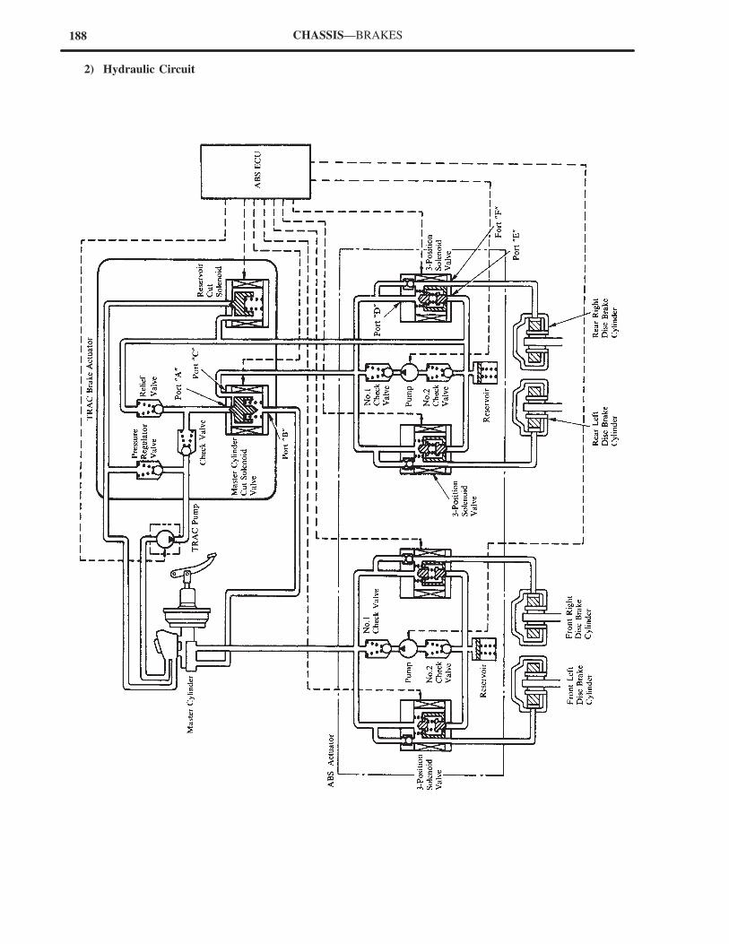
188 CHASSIS—BRAKES
2) Hydraulic Circuit
189CHASSIS—BRAKES
3) Operation
NOTE: The TRAC system effects and independent brake fluid pressure control of the right and left rear wheels.Although the explanation below deals with the right rear wheel, the operation of the left rear wheel isidentical.
a. During Normal (TRAC not Activated)
All solenoid valves of the TRAC brake actuator remain inactive when the brakes are applied. When the brake
pedal is depressed at this time, the brake fluid pressure generated by the master cylinder is applied to the disc
brake cylinders, via the master cylinder cut solenoid valve, and the 3–position solenoid valves, in the ABS
actuator. When the brake pedal is released, the brake fluid pressure returns from the disc brake cylinders to the
master cylinder.
�Condition of Each Component�
Components Operation
TRAC Pump Stop (OFF)
Master Cylinder Cut Port “A” Close
TRAC BrakeA
Master Cylinder CutSolenoid Valve Port “B” Open
Actuator Reservoir Cut SolenoidValve
Close
ABS Actuator3–Position Solenoid Port “D” Open
ABS Actuator3 Position SolenoidValve Port “E” Close
b. During Vehicle Acceleration (TRAC Operative)
When a rear wheel slips during acceleration, the TRAC system controls the engine output and braking of the rear
wheels to help prevent wheel slippage.
The brake fluid pressure applied to the right and left rear wheels is controlled separately according to 3 control
modes (pressure increase, holding, and pressure reduction) as explained below.
i) Pressure Increase Mode
When the rear wheel starts to slip just as the accelerator pedal is being depressed, all the solenoid valves in
the TRAC brake actuator are activated by signals received from the ABS ECU. At the same time, the
3–position solenoid valves in the ABS actuator are engaged in the pressure increase mode. Under this mode,
the master cylinder cut solenoid valve is activated (ports “A” and “C” open), and the reservoir cut solenoid
valve is also activated (open). Therefore, the brake fluid pressure generated by the TRAC pump is applied to
the disc brake cylinders via the master cylinder cut solenoid valve and the 3–position solenoid valves in the
ABS actuator. The TRAC pump discharge pressure is maintained constant by the pressure regulator valve.
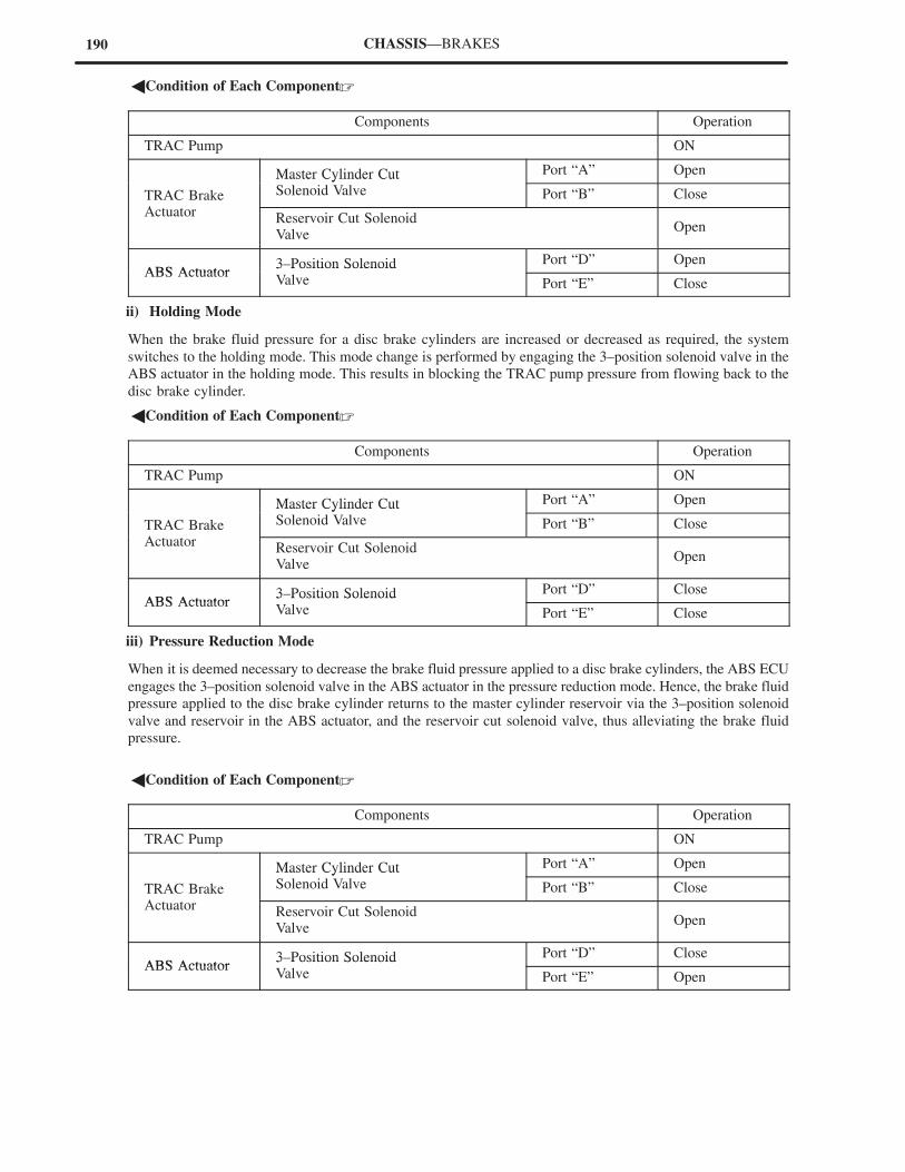
190 CHASSIS—BRAKES
�Condition of Each Component�
Components Operation
TRAC Pump ON
Master Cylinder Cut Port “A” Open
TRAC BrakeA
Master Cylinder CutSolenoid Valve Port “B” Close
Actuator Reservoir Cut SolenoidValve
Open
ABS Actuator3–Position Solenoid Port “D” Open
ABS Actuator3 Position SolenoidValve Port “E” Close
ii) Holding Mode
When the brake fluid pressure for a disc brake cylinders are increased or decreased as required, the system
switches to the holding mode. This mode change is performed by engaging the 3–position solenoid valve in the
ABS actuator in the holding mode. This results in blocking the TRAC pump pressure from flowing back to the
disc brake cylinder.
�Condition of Each Component�
Components Operation
TRAC Pump ON
Master Cylinder Cut Port “A” Open
TRAC BrakeA
Master Cylinder CutSolenoid Valve Port “B” Close
Actuator Reservoir Cut SolenoidValve
Open
ABS Actuator3–Position Solenoid Port “D” Close
ABS Actuator3 Position SolenoidValve Port “E” Close
iii) Pressure Reduction Mode
When it is deemed necessary to decrease the brake fluid pressure applied to a disc brake cylinders, the ABS ECU
engages the 3–position solenoid valve in the ABS actuator in the pressure reduction mode. Hence, the brake fluid
pressure applied to the disc brake cylinder returns to the master cylinder reservoir via the 3–position solenoid
valve and reservoir in the ABS actuator, and the reservoir cut solenoid valve, thus alleviating the brake fluid
pressure.
�Condition of Each Component�
Components Operation
TRAC Pump ON
Master Cylinder Cut Port “A” Open
TRAC BrakeA
Master Cylinder CutSolenoid Valve Port “B” Close
Actuator Reservoir Cut SolenoidValve
Open
ABS Actuator3–Position Solenoid Port “D” Close
ABS Actuator3 Position SolenoidValve Port “E” Open
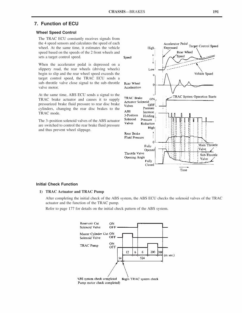
191CHASSIS—BRAKES
7. Function of ECU
Wheel Speed Control
The TRAC ECU constantly receives signals from
the 4 speed sensors and calculates the speed of each
wheel. At the same time, it estimates the vehicle
speed based on the speeds of the 2 front wheels and
sets a target control speed.
When the accelerator pedal is depressed on a
slippery road, the rear wheels (driving wheels)
begin to slip and the rear wheel speed exceeds the
target control speed, the TRAC ECU sends a
sub–throttle valve close signal to the sub–throttle
valve motor.
At the same time, ABS ECU sends a signal to the
TRAC brake actuator and causes it to supply
pressurized brake fluid pressure to rear disc brake
cylinders, changing the rear disc brakes to the
TRAC mode.
The 3–position solenoid valves of the ABS actuator
are switched to control the rear brake fluid pressure
and thus prevent wheel slippage.
Initial Check Function
1) TRAC Actuator and TRAC Pump
After completing the initial check of the ABS system, the ABS ECU checks the solenoid valves of the TRAC
actuator and the function of the TRAC pump.
Refer to page 177 for details on the initial check pattern of the ABS system.
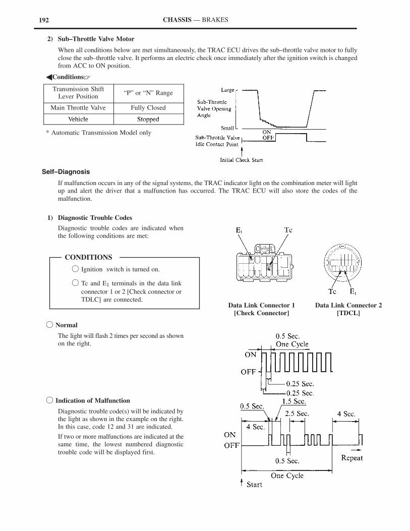
192
Data Link Connector 1
[Check Connector]
Data Link Connector 2
[TDCL]
� Ignition switch is turned on.
� Tc and E1 terminals in the data link
connector 1 or 2 [Check connector or
TDLC] are connected.
CONDITIONS
CHASSIS — BRAKES
2) Sub–Throttle Valve Motor
When all conditions below are met simultaneously, the TRAC ECU drives the sub–throttle valve motor to fully
close the sub–throttle valve. It performs an electric check once immediately after the ignition switch is changed
from ACC to ON position.
�Conditions�
Transmission ShiftLever Position
“P” or “N” Range
Main Throttle Valve Fully Closed
Vehicle StoppedVehicle Stopped
* Automatic Transmission Model only
Self–Diagnosis
If malfunction occurs in any of the signal systems, the TRAC indicator light on the combination meter will light
up and alert the driver that a malfunction has occurred. The TRAC ECU will also store the codes of the
malfunction.
1) Diagnostic Trouble Codes
Diagnostic trouble codes are indicated when
the following conditions are met:
� Normal
The light will flash 2 times per second as shown
on the right.
� Indication of Malfunction
Diagnostic trouble code(s) will be indicated by
the light as shown in the example on the right.
In this case, code 12 and 31 are indicated.
If two or more malfunctions are indicated at the
same time, the lowest numbered diagnostic
trouble code will be displayed first.
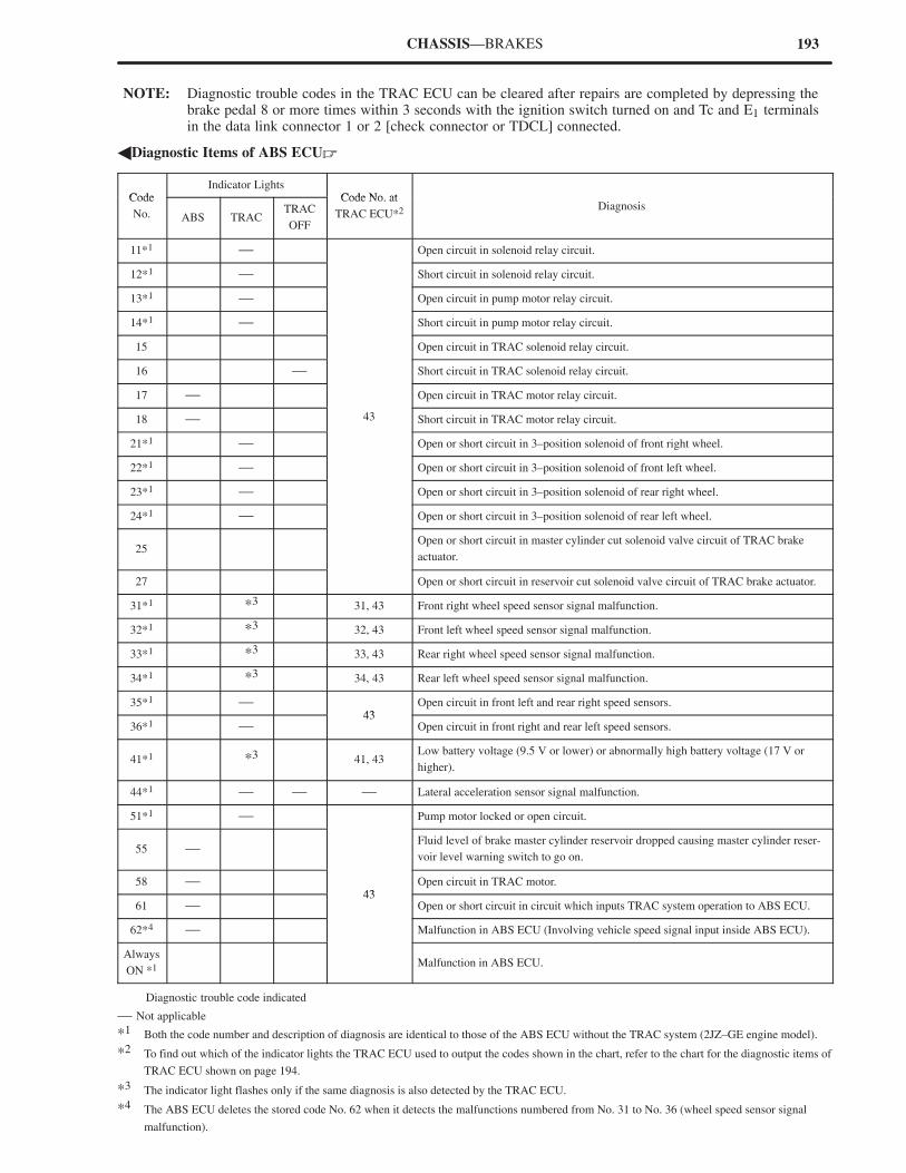
193CHASSIS—BRAKES
NOTE: Diagnostic trouble codes in the TRAC ECU can be cleared after repairs are completed by depressing thebrake pedal 8 or more times within 3 seconds with the ignition switch turned on and Tc and E1 terminalsin the data link connector 1 or 2 [check connector or TDCL] connected.
�Diagnostic Items of ABS ECU�
CodeIndicator Lights
Code No atCode
No. ABS TRACTRAC
OFF
Code No. at
TRAC ECU*2 Diagnosis
11*1 — Open circuit in solenoid relay circuit.
12*1 — Short circuit in solenoid relay circuit.
13*1 — Open circuit in pump motor relay circuit.
14*1 — Short circuit in pump motor relay circuit.
15 Open circuit in TRAC solenoid relay circuit.
16 — Short circuit in TRAC solenoid relay circuit.
17 — Open circuit in TRAC motor relay circuit.
18 — 43 Short circuit in TRAC motor relay circuit.
21*1 — Open or short circuit in 3–position solenoid of front right wheel.
22*1 — Open or short circuit in 3–position solenoid of front left wheel.
23*1 — Open or short circuit in 3–position solenoid of rear right wheel.
24*1 — Open or short circuit in 3–position solenoid of rear left wheel.
25 Open or short circuit in master cylinder cut solenoid valve circuit of TRAC brake
actuator.
27 Open or short circuit in reservoir cut solenoid valve circuit of TRAC brake actuator.
31*1 *3 31, 43 Front right wheel speed sensor signal malfunction.
32*1 *3 32, 43 Front left wheel speed sensor signal malfunction.
33*1 *3 33, 43 Rear right wheel speed sensor signal malfunction.
34*1 *3 34, 43 Rear left wheel speed sensor signal malfunction.
35*1 — 43
Open circuit in front left and rear right speed sensors.
36*1 — 43
Open circuit in front right and rear left speed sensors.
41*1 *3 41, 43Low battery voltage (9.5 V or lower) or abnormally high battery voltage (17 V or
higher).
44*1 — — — Lateral acceleration sensor signal malfunction.
51*1 — Pump motor locked or open circuit.
55 — Fluid level of brake master cylinder reservoir dropped causing master cylinder reser-
voir level warning switch to go on.
58 — 43
Open circuit in TRAC motor.
61 — 43
Open or short circuit in circuit which inputs TRAC system operation to ABS ECU.
62*4 — Malfunction in ABS ECU (Involving vehicle speed signal input inside ABS ECU).
Always
ON *1 Malfunction in ABS ECU.
Diagnostic trouble code indicated
— Not applicable
*1 Both the code number and description of diagnosis are identical to those of the ABS ECU without the TRAC system (2JZ–GE engine model).
*2 To find out which of the indicator lights the TRAC ECU used to output the codes shown in the chart, refer to the chart for the diagnostic items of
TRAC ECU shown on page 194.
*3 The indicator light flashes only if the same diagnosis is also detected by the TRAC ECU.
*4 The ABS ECU deletes the stored code No. 62 when it detects the malfunctions numbered from No. 31 to No. 36 (wheel speed sensor signal
malfunction).
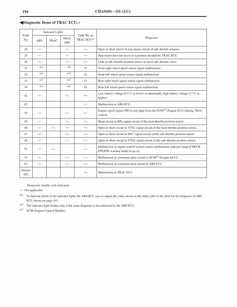
194 CHASSIS—BRAKES
�Diagnostic Items of TRAC ECU�
CodeIndicator Lights
Code No atCode
No. ABS TRACTRAC
OFF
Code No. at
TRAC ECU*1 Diagnosis
24 — — — Open or short circuit in step motor circuit of sub–throttle actuator.
25 — — — Step motor does not move to a position decided by TRAC ECU.
26 — — — Leak at sub–throttle position sensor or stuck sub–throttle valve.
31 *2 *2 31 Front right wheel speed sensor signal malfunction.
32 *2 *2 32 Front left wheel speed sensor signal malfunction.
33 *2 *2 33 Rear right wheel speed sensor signal malfunction.
34 *2 *2 34 Rear left wheel speed sensor signal malfunction.
41 — — —Low battery voltage (9.5 V or lower) or abnormally high battery voltage (17 V or
higher)
43 — Malfunction in ABS ECU.
44 — — —Engine speed signal (NE) is not input from the ECM*3 [Engine ECU] during TRAC
control.
45 — — — Short circuit in IDL signal circuit of the main throttle position sensor.
46 — — — — Open or short circuit in VTA1 signal circuit of the main throttle position sensor.
47 — — — Open or short circuit in IDL2 signal circuit of the sub–throttle position sensor.
48 — — — Open or short circuit in VTA2 signal circuit of the sub–throttle position sensor.
51 — — —Malfunction in engine control system causes malfunction indicator lamp [CHECK
ENGINE warning lamp] to go on.
53 — — — Malfunction in communication circuit to ECM*3 [Engine ECU].
61 — — — Malfunction in communication circuit to ABS ECU.
Always
ON — Malfunction in TRAC ECU.
Diagnostic trouble code indicated
— Not applicable
*1 To find out which of the indicator lights the ABS ECU uses to output the codes shown in the chart, refer to the chart for the diagnosis of ABS
ECU shown on page 193.
*2 The indicator light flashes only if the same diagnosis is also detected by the ABS ECU.
*3 ECM (Engine Control Module)

195CHASSIS—BRAKES
Fail–Safe
When a malfunction occurs while the TRAC system is inoperative, the TRAC ECU immediately turns off the TRAC
motor relay and TRAC solenoid relay, and stops the TRAC system operation. When the TRAC system is operative,
the TRAC ECU continues control, stops the control, or fully opens the sub–throttle valve depending on the types of
malfunction.
After the TRAC system becomes inoperative, the engine and brake system operates in the same way as on models
without the TRAC system.
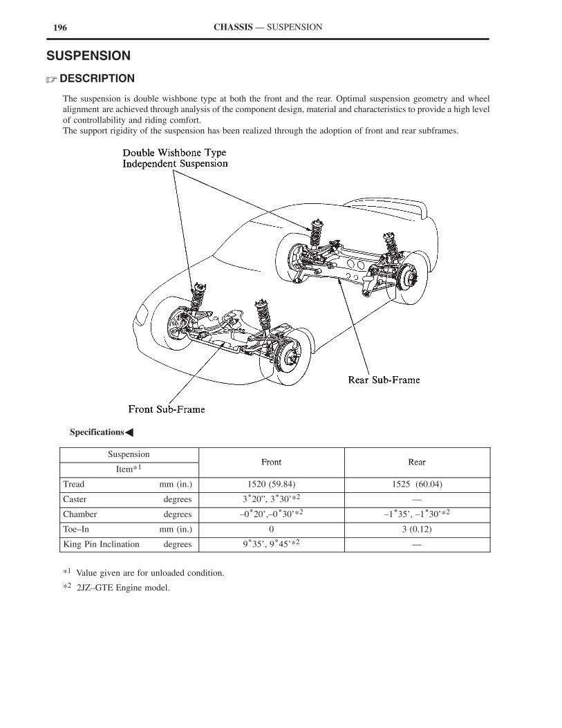
196 CHASSIS — SUSPENSION
SUSPENSION
� DESCRIPTION
The suspension is double wishbone type at both the front and the rear. Optimal suspension geometry and wheel
alignment are achieved through analysis of the component design, material and characteristics to provide a high level
of controllability and riding comfort.
The support rigidity of the suspension has been realized through the adoption of front and rear subframes.
�Specifications�
SuspensionFront Rear
Item*1Front Rear
Tread mm (in.) 1520 (59.84) 1525 (60.04)
Caster degrees 3°20”, 3°30’*2 —
Chamber degrees –0°20’,–0°30’*2 –1°35’, –1°30’*2
Toe–In mm (in.) 0 3 (0.12)
King Pin Inclination degrees 9°35’, 9°45’*2 —
*1 Value given are for unloaded condition.
*2 2JZ–GTE Engine model.
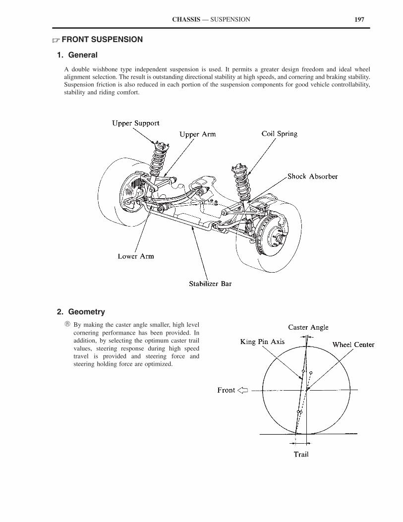
197CHASSIS — SUSPENSION
� FRONT SUSPENSION
1. General
A double wishbone type independent suspension is used. It permits a greater design freedom and ideal wheel
alignment selection. The result is outstanding directional stability at high speeds, and cornering and braking stability.
Suspension friction is also reduced in each portion of the suspension components for good vehicle controllability,
stability and riding comfort.
2. Geometry
� By making the caster angle smaller, high level
cornering performance has been provided. In
addition, by selecting the optimum caster trail
values, steering response during high speed
travel is provided and steering force and
steering holding force are optimized.
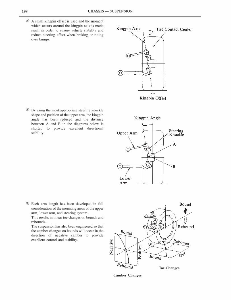
198
Camber Changes
Toe Changes
CHASSIS — SUSPENSION
� A small kingpin offset is used and the moment
which occurs around the kingpin axis is made
small in order to ensure vehicle stability and
reduce steering effort when braking or riding
over bumps.
� By using the most appropriate steering knuckle
shape and position of the upper arm, the kingpin
angle has been reduced and the distance
between A and B in the diagrams below is
shorted to provide excellent directional
stability.
� Each arm length has been developed in full
consideration of the mounting areas of the upper
arm, lower arm, and steering system.
This results in linear toe changes on bounds and
rebounds.
The suspension has also been engineered so that
the camber changes on bounds will occur in the
direction of negative camber to provide
excellent control and stability.
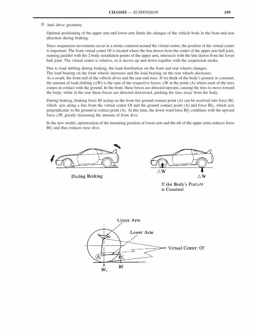
199CHASSIS — SUSPENSION
� Anti–drive geometry
Optimal positioning of the upper arm and lower arm limits the changes of the vehicle body in the front and rear
direction during braking.
Since suspension movements occur in a stroke centered around the virtual center, the position of the virtual center
is important. The front virtual center Of is located where the line drawn from the center of the upper arm ball joint,
running parallel with the 2 body installation points of the upper arm, intersects with the line drawn from the lower
ball joint. The virtual center is relative, so it moves up and down together with the suspension stroke.
Due to load shifting during braking, the load distribution on the front and rear wheels changes.
The load bearing on the front wheels increases and the load bearing on the rear wheels decreases.
As a result, the front end of the vehicle dives and the rear end rises. If we think of the body’s posture as constant,
the amount of load shifting (�W) is the sum of the respective forces �W at the point (A) where each of the tires
comes in contact with the ground. In the front, these forces are directed upward, causing the tires to move toward
the body, while in the rear these forces are directed downward, pushing the tires away from the body.
During braking, braking force Bf acting on the front tire ground contact point (A) can be resolved into force Bf1
which acts along a line from the virtual center Of and the ground contact point (A) and force Bf2, which acts
perpendicular to the ground at contact point (A). At this time, the down ward force Bf2 combines with the upward
force �W, greatly increasing the amount of front dive.
In the new model, optimization of the mounting position of lower arm and the tilt of the upper arms reduces force
Bf2 and thus reduces nose dive.
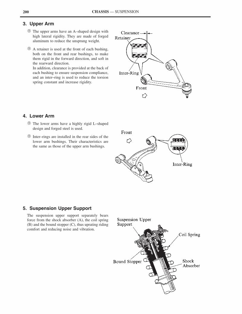
200 CHASSIS — SUSPENSION
3. Upper Arm
� The upper arms have an A–shaped design with
high lateral rigidity. They are made of forged
aluminum to reduce the unsprung weight.
� A retainer is used at the front of each bushing,
both on the front and rear bushings, to make
them rigid in the forward direction, and soft in
the rearward direction.
In addition, clearance is provided at the back of
each bushing to ensure suspension compliance,
and an inter–ring is used to reduce the torsion
spring constant and increase rigidity.
4. Lower Arm
� The lower arms have a highly rigid L–shaped
design and forged steel is used.
� Inter–rings are installed in the rear sides of the
lower arm bushings. Their characteristics are
the same as those of the upper arm bushings.
5. Suspension Upper Support
The suspension upper support separately bears
force from the shock absorber (A), the coil spring
(B) and the bound stopper (C), thus uprating riding
comfort and reducing noise and vibration.
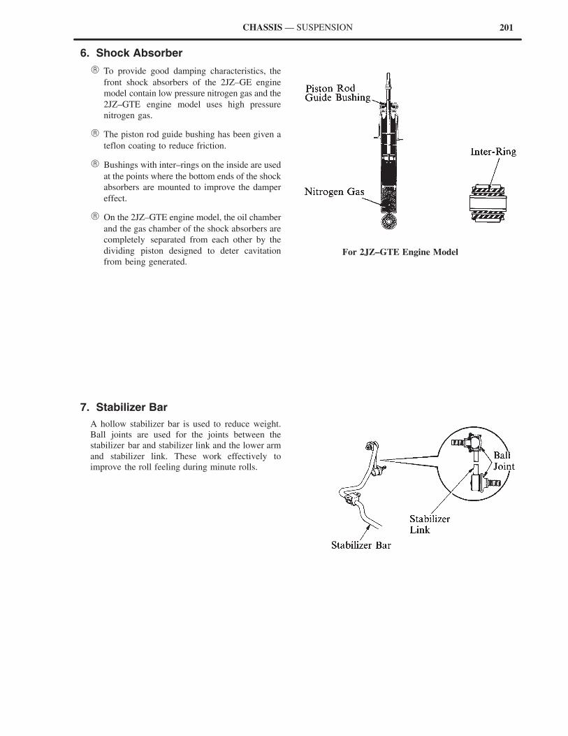
201
For 2JZ–GTE Engine Model
CHASSIS — SUSPENSION
6. Shock Absorber
� To provide good damping characteristics, the
front shock absorbers of the 2JZ–GE engine
model contain low pressure nitrogen gas and the
2JZ–GTE engine model uses high pressure
nitrogen gas.
� The piston rod guide bushing has been given a
teflon coating to reduce friction.
� Bushings with inter–rings on the inside are used
at the points where the bottom ends of the shock
absorbers are mounted to improve the damper
effect.
� On the 2JZ–GTE engine model, the oil chamber
and the gas chamber of the shock absorbers are
completely separated from each other by the
dividing piston designed to deter cavitation
from being generated.
7. Stabilizer Bar
A hollow stabilizer bar is used to reduce weight.
Ball joints are used for the joints between the
stabilizer bar and stabilizer link and the lower arm
and stabilizer link. These work effectively to
improve the roll feeling during minute rolls.

202 CHASSIS — SUSPENSION
� REAR SUSPENSION
1. General
The rear suspension is the same double wishbone type as the front. The A–shaped aluminum upper arm is combined
with two unequal–length, non–parallel lower arms and a strut rod.
2. Geometry
� The combination of long lower arm and short
upper arm provides optimal camber and tread
changes during bound and rebound.
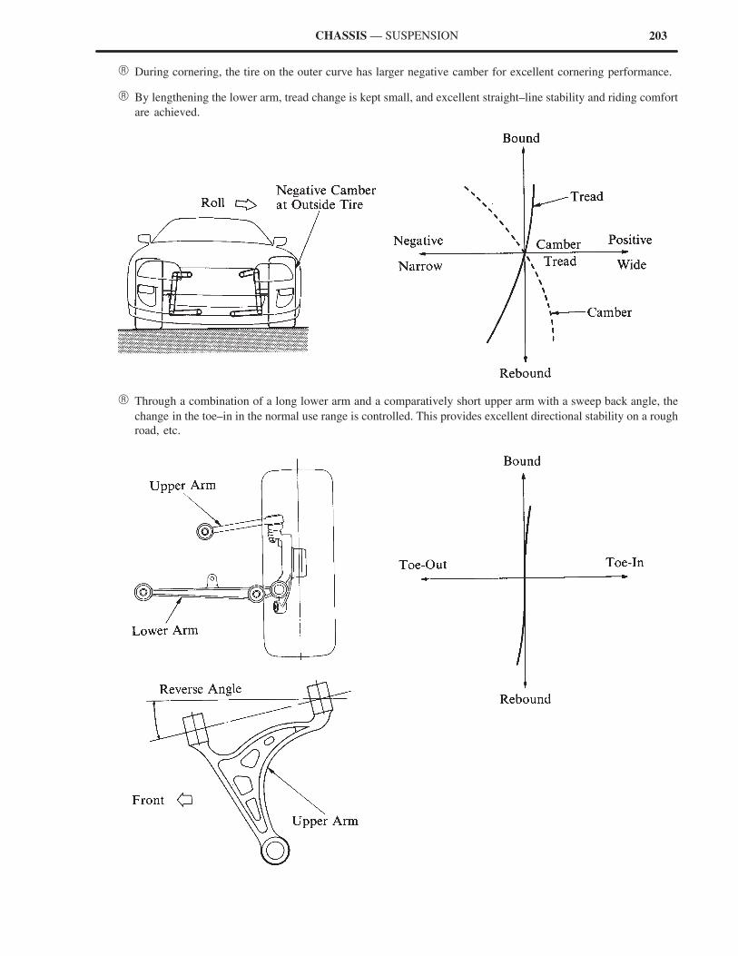
203CHASSIS — SUSPENSION
� During cornering, the tire on the outer curve has larger negative camber for excellent cornering performance.
� By lengthening the lower arm, tread change is kept small, and excellent straight–line stability and riding comfort
are achieved.
� Through a combination of a long lower arm and a comparatively short upper arm with a sweep back angle, the
change in the toe–in in the normal use range is controlled. This provides excellent directional stability on a rough
road, etc.
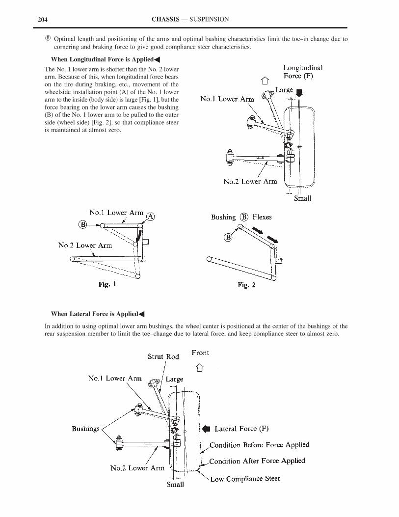
204 CHASSIS — SUSPENSION
� Optimal length and positioning of the arms and optimal bushing characteristics limit the toe–in change due to
cornering and braking force to give good compliance steer characteristics.
�When Longitudinal Force is Applied�
The No. 1 lower arm is shorter than the No. 2 lower
arm. Because of this, when longitudinal force bears
on the tire during braking, etc., movement of the
wheelside installation point (A) of the No. 1 lower
arm to the inside (body side) is large [Fig. 1], but the
force bearing on the lower arm causes the bushing
(B) of the No. 1 lower arm to be pulled to the outer
side (wheel side) [Fig. 2], so that compliance steer
is maintained at almost zero.
�When Lateral Force is Applied�
In addition to using optimal lower arm bushings, the wheel center is positioned at the center of the bushings of the
rear suspension member to limit the toe–change due to lateral force, and keep compliance steer to almost zero.
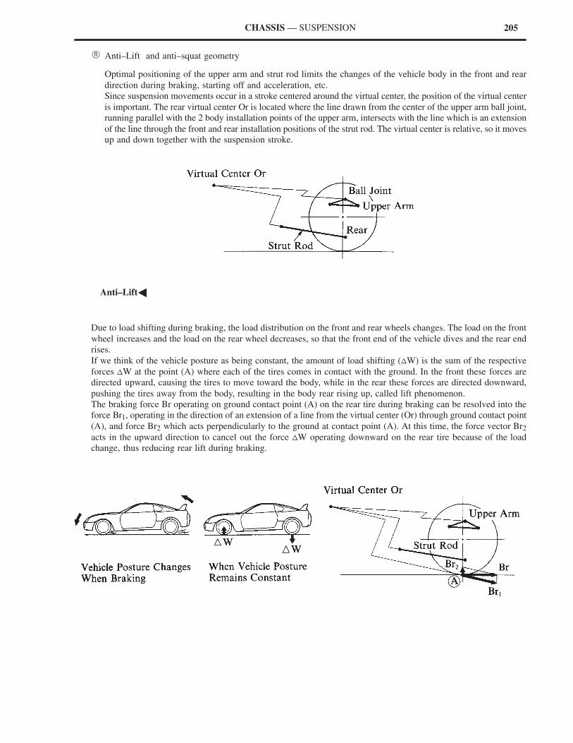
205CHASSIS — SUSPENSION
� Anti–Lift and anti–squat geometry
Optimal positioning of the upper arm and strut rod limits the changes of the vehicle body in the front and rear
direction during braking, starting off and acceleration, etc.
Since suspension movements occur in a stroke centered around the virtual center, the position of the virtual center
is important. The rear virtual center Or is located where the line drawn from the center of the upper arm ball joint,
running parallel with the 2 body installation points of the upper arm, intersects with the line which is an extension
of the line through the front and rear installation positions of the strut rod. The virtual center is relative, so it moves
up and down together with the suspension stroke.
�Anti–Lift�
Due to load shifting during braking, the load distribution on the front and rear wheels changes. The load on the front
wheel increases and the load on the rear wheel decreases, so that the front end of the vehicle dives and the rear end
rises.
If we think of the vehicle posture as being constant, the amount of load shifting (�W) is the sum of the respective
forces �W at the point (A) where each of the tires comes in contact with the ground. In the front these forces are
directed upward, causing the tires to move toward the body, while in the rear these forces are directed downward,
pushing the tires away from the body, resulting in the body rear rising up, called lift phenomenon.
The braking force Br operating on ground contact point (A) on the rear tire during braking can be resolved into the
force Br1, operating in the direction of an extension of a line from the virtual center (Or) through ground contact point
(A), and force Br2 which acts perpendicularly to the ground at contact point (A). At this time, the force vector Br2
acts in the upward direction to cancel out the force �W operating downward on the rear tire because of the load
change, thus reducing rear lift during braking.
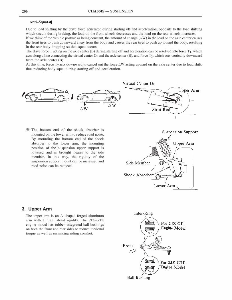
206 CHASSIS — SUSPENSION
�Anti–Squat�
Due to load shifting by the drive force generated during starting off and acceleration, opposite to the load shifting
which occurs during braking, the load on the front wheels decreases and the load on the rear wheels increases.
If we think of the vehicle posture as being constant, the amount of change (�W) in the load on the axle center causes
the front tires to push downward away from the body and causes the rear tires to push up toward the body, resulting
in the rear body dropping so that squat occurs.
The drive force T acting on the axle center (B) during starting off and acceleration can be resolved into force T1, which
acts along a line connecting the virtual center Or and the axle center (B), and force T2, which acts vertically downward
from the axle center (B).
At this time, force T2 acts downward to cancel out the force �W acting upward on the axle center due to load shift,
thus reducing body squat during starting off and acceleration.
� The bottom end of the shock absorber is
mounted on the lower arm to reduce road noise.
By mounting the bottom end of the shock
absorber to the lower arm, the mounting
position of the suspension upper support is
lowered and is brought nearer to the side
member. In this way, the rigidity of the
suspension support mount can be increased and
road noise can be reduced.
3. Upper Arm
The upper arm is an A–shaped forged aluminum
arm with a high lateral rigidity. The 2JZ–GTE
engine model has rubber–integrated ball bushings
on both the front and rear sides to reduce torsional
torque as well as enhancing riding comfort.
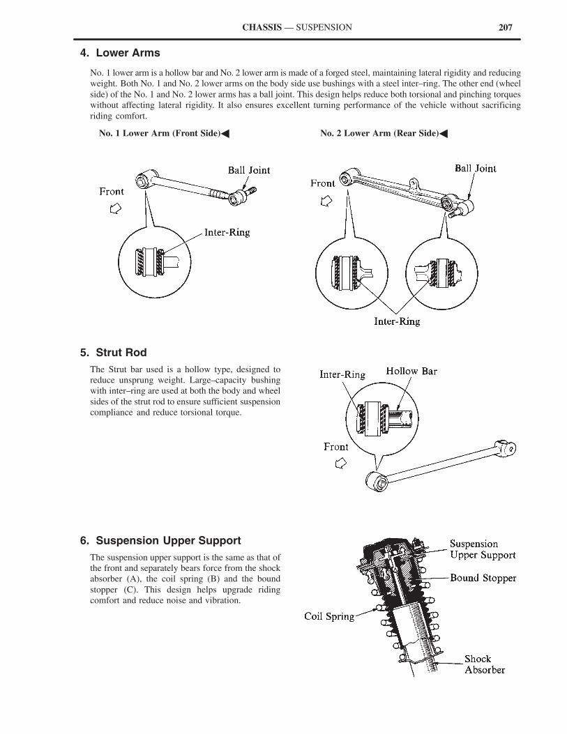
207CHASSIS — SUSPENSION
4. Lower Arms
No. 1 lower arm is a hollow bar and No. 2 lower arm is made of a forged steel, maintaining lateral rigidity and reducing
weight. Both No. 1 and No. 2 lower arms on the body side use bushings with a steel inter–ring. The other end (wheel
side) of the No. 1 and No. 2 lower arms has a ball joint. This design helps reduce both torsional and pinching torques
without affecting lateral rigidity. It also ensures excellent turning performance of the vehicle without sacrificing
riding comfort.
�No. 1 Lower Arm (Front Side)� �No. 2 Lower Arm (Rear Side)�
5. Strut Rod
The Strut bar used is a hollow type, designed to
reduce unsprung weight. Large–capacity bushing
with inter–ring are used at both the body and wheel
sides of the strut rod to ensure sufficient suspension
compliance and reduce torsional torque.
6. Suspension Upper Support
The suspension upper support is the same as that of
the front and separately bears force from the shock
absorber (A), the coil spring (B) and the bound
stopper (C). This design helps upgrade riding
comfort and reduce noise and vibration.
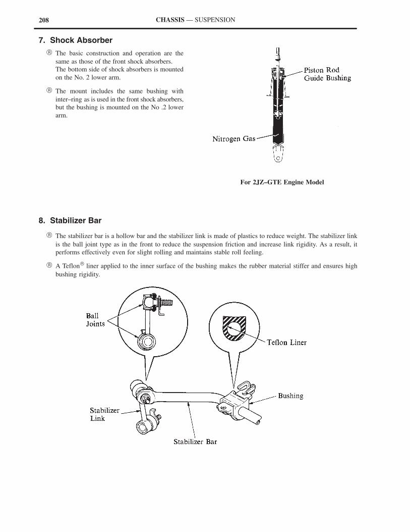
208
For 2JZ–GTE Engine Model
CHASSIS — SUSPENSION
7. Shock Absorber
� The basic construction and operation are the
same as those of the front shock absorbers.
The bottom side of shock absorbers is mounted
on the No. 2 lower arm.
� The mount includes the same bushing with
inter–ring as is used in the front shock absorbers,
but the bushing is mounted on the No .2 lower
arm.
8. Stabilizer Bar
� The stabilizer bar is a hollow bar and the stabilizer link is made of plastics to reduce weight. The stabilizer link
is the ball joint type as in the front to reduce the suspension friction and increase link rigidity. As a result, it
performs effectively even for slight rolling and maintains stable roll feeling.
� A Teflon liner applied to the inner surface of the bushing makes the rubber material stiffer and ensures high
bushing rigidity.
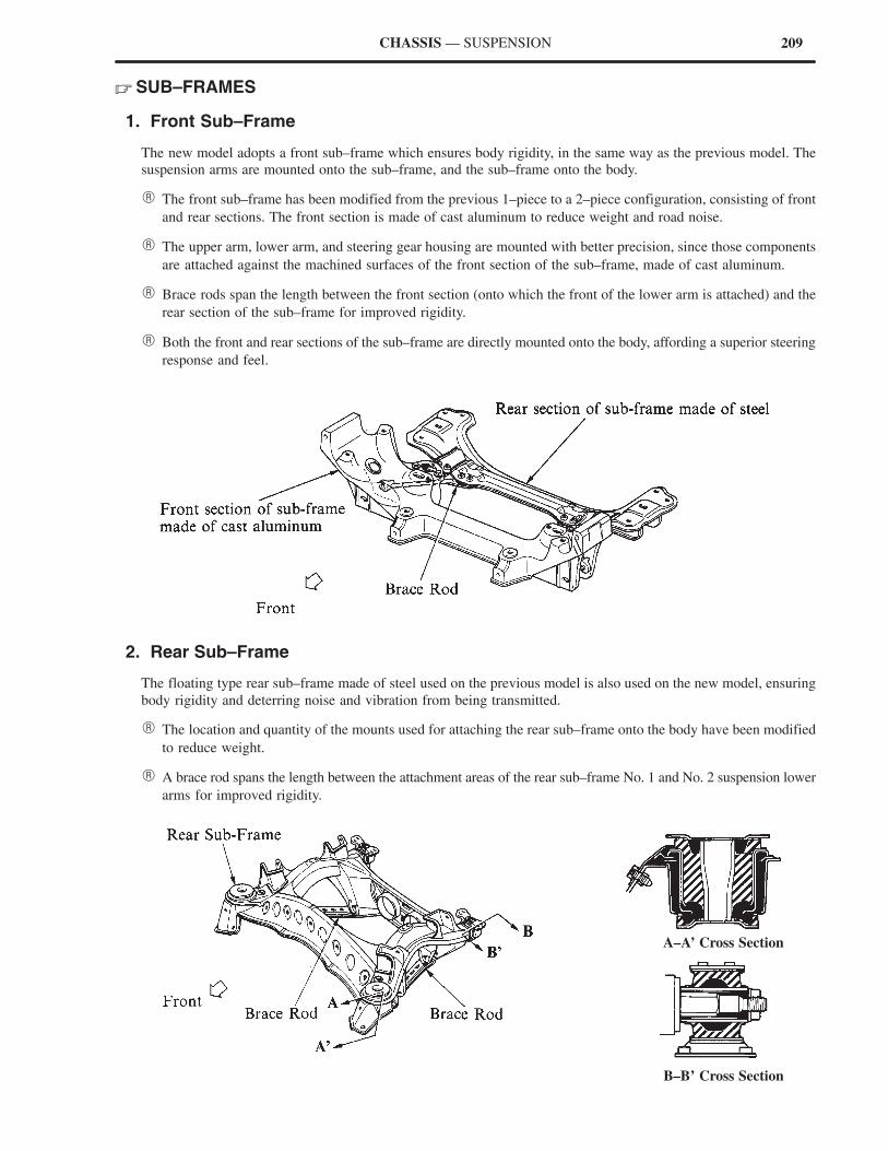
209CHASSIS — SUSPENSION
� SUB–FRAMES
1. Front Sub–Frame
The new model adopts a front sub–frame which ensures body rigidity, in the same way as the previous model. The
suspension arms are mounted onto the sub–frame, and the sub–frame onto the body.
� The front sub–frame has been modified from the previous 1–piece to a 2–piece configuration, consisting of front
and rear sections. The front section is made of cast aluminum to reduce weight and road noise.
� The upper arm, lower arm, and steering gear housing are mounted with better precision, since those components
are attached against the machined surfaces of the front section of the sub–frame, made of cast aluminum.
� Brace rods span the length between the front section (onto which the front of the lower arm is attached) and the
rear section of the sub–frame for improved rigidity.
� Both the front and rear sections of the sub–frame are directly mounted onto the body, affording a superior steering
response and feel.
2. Rear Sub–Frame
The floating type rear sub–frame made of steel used on the previous model is also used on the new model, ensuring
body rigidity and deterring noise and vibration from being transmitted.
� The location and quantity of the mounts used for attaching the rear sub–frame onto the body have been modified
to reduce weight.
� A brace rod spans the length between the attachment areas of the rear sub–frame No. 1 and No. 2 suspension lower
arms for improved rigidity.
A–A’ Cross Section
B–B’ Cross Section
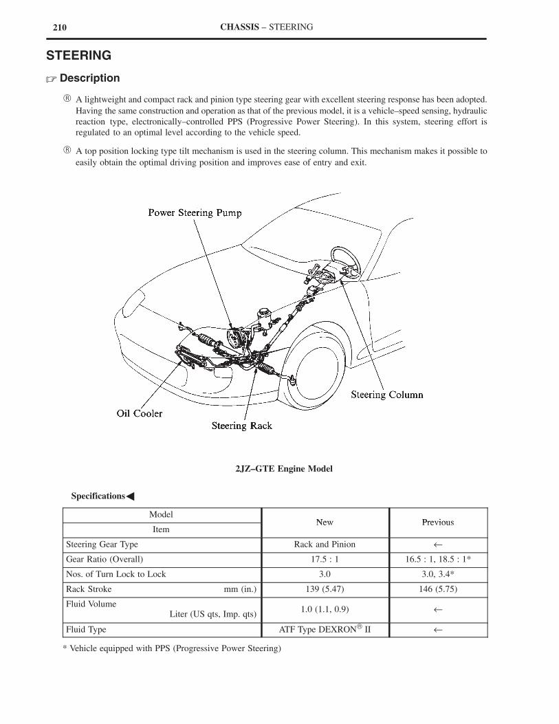
210 CHASSIS – STEERING
STEERING
� Description
� A lightweight and compact rack and pinion type steering gear with excellent steering response has been adopted.
Having the same construction and operation as that of the previous model, it is a vehicle–speed sensing, hydraulic
reaction type, electronically–controlled PPS (Progressive Power Steering). In this system, steering effort is
regulated to an optimal level according to the vehicle speed.
� A top position locking type tilt mechanism is used in the steering column. This mechanism makes it possible to
easily obtain the optimal driving position and improves ease of entry and exit.
2JZ–GTE Engine Model
�Specifications�
ModelNew Previous
ItemNew Previous
Steering Gear Type Rack and Pinion ←
Gear Ratio (Overall) 17.5 : 1 16.5 : 1, 18.5 : 1*
Nos. of Turn Lock to Lock 3.0 3.0, 3.4*
Rack Stroke mm (in.) 139 (5.47) 146 (5.75)
Fluid VolumeLiter (US qts, Imp. qts)
1.0 (1.1, 0.9) ←
Fluid Type ATF Type DEXRON II ←
* Vehicle equipped with PPS (Progressive Power Steering)
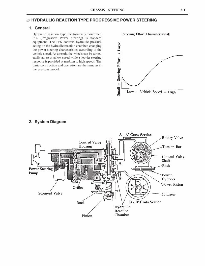
211CHASSIS—STEERING
� HYDRAULIC REACTION TYPE PROGRESSIVE POWER STEERING
1. General
Hydraulic reaction type electronically controlled
PPS (Progressive Power Steering) is standard
equipment. The PPS controls hydraulic pressure
acting on the hydraulic reaction chamber, changing
the power steering characteristics according to the
vehicle speed. As a result, the wheels can be turned
easily at rest or at low speed while a heavier steering
response is provided at medium to high speeds. The
basic construction and operation are the same as in
the previous model.
�Steering Effort Characteristic�
2. System Diagram
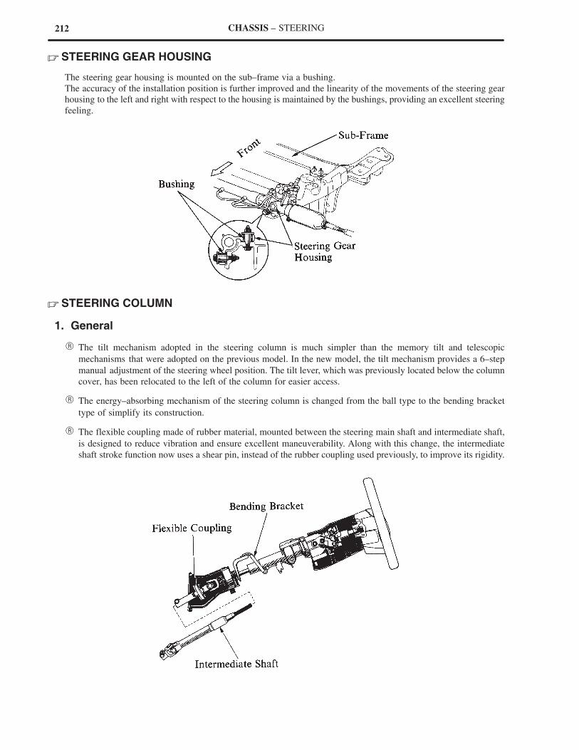
212 CHASSIS – STEERING
� STEERING GEAR HOUSING
The steering gear housing is mounted on the sub–frame via a bushing.
The accuracy of the installation position is further improved and the linearity of the movements of the steering gear
housing to the left and right with respect to the housing is maintained by the bushings, providing an excellent steering
feeling.
� STEERING COLUMN
1. General
� The tilt mechanism adopted in the steering column is much simpler than the memory tilt and telescopic
mechanisms that were adopted on the previous model. In the new model, the tilt mechanism provides a 6–step
manual adjustment of the steering wheel position. The tilt lever, which was previously located below the column
cover, has been relocated to the left of the column for easier access.
� The energy–absorbing mechanism of the steering column is changed from the ball type to the bending bracket
type of simplify its construction.
� The flexible coupling made of rubber material, mounted between the steering main shaft and intermediate shaft,
is designed to reduce vibration and ensure excellent maneuverability. Along with this change, the intermediate
shaft stroke function now uses a shear pin, instead of the rubber coupling used previously, to improve its rigidity.
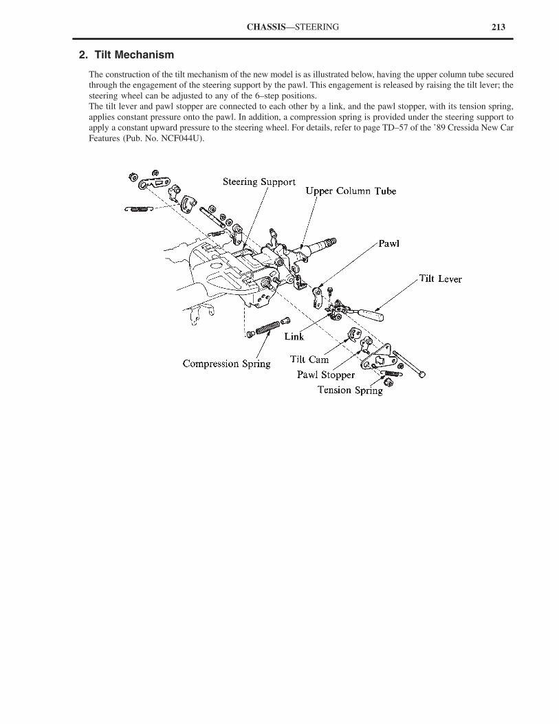
213CHASSIS—STEERING
2. Tilt Mechanism
The construction of the tilt mechanism of the new model is as illustrated below, having the upper column tube secured
through the engagement of the steering support by the pawl. This engagement is released by raising the tilt lever; the
steering wheel can be adjusted to any of the 6–step positions.
The tilt lever and pawl stopper are connected to each other by a link, and the pawl stopper, with its tension spring,
applies constant pressure onto the pawl. In addition, a compression spring is provided under the steering support to
apply a constant upward pressure to the steering wheel. For details, refer to page TD–57 of the ’89 Cressida New Car
Features (Pub. No. NCF044U).
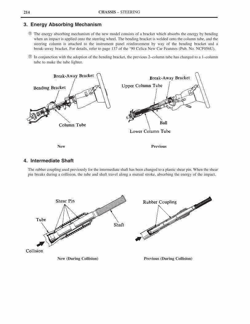
214 CHASSIS – STEERING
3. Energy Absorbing Mechanism
� The energy absorbing mechanism of the new model consists of a bracket which absorbs the energy by bending
when an impact is applied onto the steering wheel. The bending bracket is welded onto the column tube, and the
steering column is attached to the instrument panel reinforcement by way of the bending bracket and a
break–away bracket. For details, refer to page 137 of the ’90 Celica New Car Features (Pub. No. NCF056U).
� In conjunction with the adoption of the bending bracket, the previous 2–column tube has changed to a 1–column
tube to make the tube lighter.
New Previous
4. Intermediate Shaft
The rubber coupling used previously for the intermediate shaft has been changed to a plastic shear pin. When the shear
pin breaks during a collision, the tube and shaft travel along a mutual stroke, absorbing the energy of the impact.
New (During Collision) Previous (During Collision)
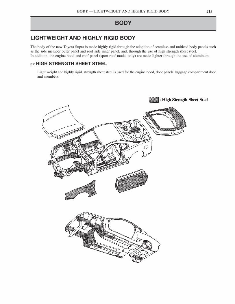
215BODY — LIGHTWEIGHT AND HIGHLY RIGID BODY
BODY
LIGHTWEIGHT AND HIGHLY RIGID BODY
The body of the new Toyota Supra is made highly rigid through the adoption of seamless and unitized body panels such
as the side member outer panel and roof side inner panel, and, through the use of high strength sheet steel.
In addition, the engine hood and roof panel (sport roof model only) are made lighter through the use of aluminum.
� HIGH STRENGTH SHEET STEEL
Light weight and highly rigid strength sheet steel is used for the engine hood, door panels, luggage compartment door
and members.
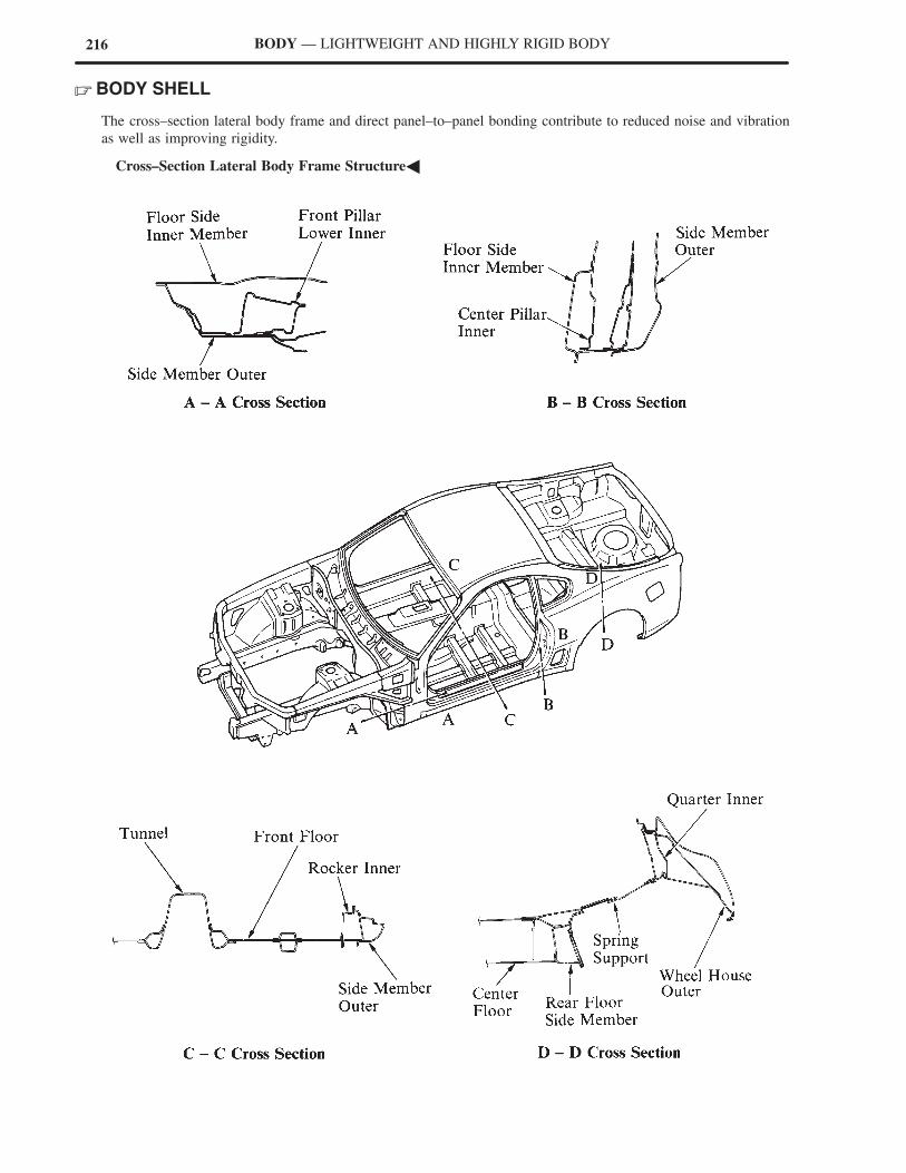
216 BODY — LIGHTWEIGHT AND HIGHLY RIGID BODY
� BODY SHELL
The cross–section lateral body frame and direct panel–to–panel bonding contribute to reduced noise and vibration
as well as improving rigidity.
�Cross–Section Lateral Body Frame Structure�
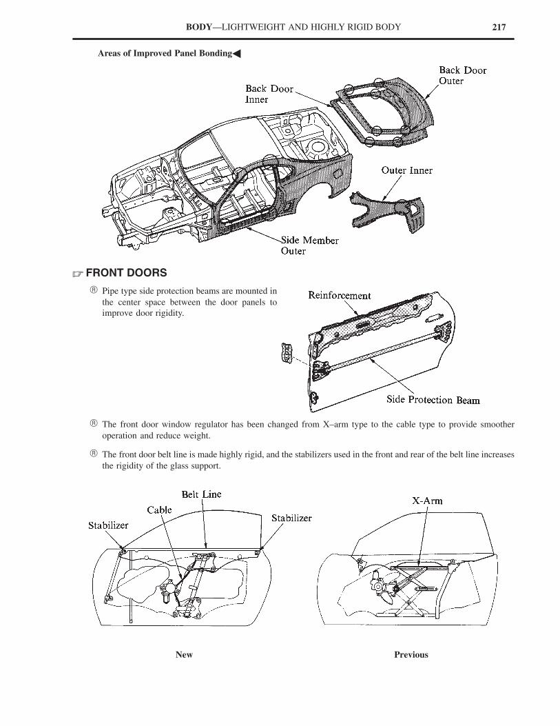
217BODY—LIGHTWEIGHT AND HIGHLY RIGID BODY
�Areas of Improved Panel Bonding�
� FRONT DOORS
� Pipe type side protection beams are mounted in
the center space between the door panels to
improve door rigidity.
� The front door window regulator has been changed from X–arm type to the cable type to provide smoother
operation and reduce weight.
� The front door belt line is made highly rigid, and the stabilizers used in the front and rear of the belt line increases
the rigidity of the glass support.
New Previous
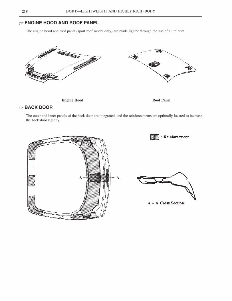
218 BODY—LIGHTWEIGHT AND HIGHLY RIGID BODY
� ENGINE HOOD AND ROOF PANEL
The engine hood and roof panel (sport roof model only) are made lighter through the use of aluminum.
Engine Hood Roof Panel
� BACK DOOR
The outer and inner panels of the back door are integrated, and the reinforcements are optimally located to increase
the back door rigidity.
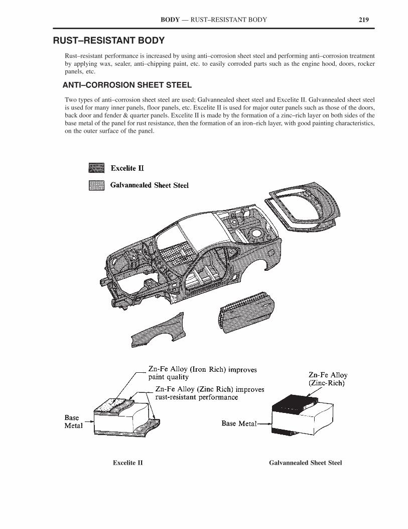
219BODY — RUST–RESISTANT BODY
RUST–RESISTANT BODY
Rust–resistant performance is increased by using anti–corrosion sheet steel and performing anti–corrosion treatment
by applying wax, sealer, anti–chipping paint, etc. to easily corroded parts such as the engine hood, doors, rocker
panels, etc.
� ANTI–CORROSION SHEET STEEL
Two types of anti–corrosion sheet steel are used; Galvannealed sheet steel and Excelite II. Galvannealed sheet steel
is used for many inner panels, floor panels, etc. Excelite II is used for major outer panels such as those of the doors,
back door and fender & quarter panels. Excelite II is made by the formation of a zinc–rich layer on both sides of the
base metal of the panel for rust resistance, then the formation of an iron–rich layer, with good painting characteristics,
on the outer surface of the panel.
Excelite II Galvannealed Sheet Steel
220 BODY — RUST–RESISTANT BODY
� WAX AND SEALER
Wax and sealer is applied to the hemmed portions of the door panels and back door to improve rust–resistant
performance.
� UNDER COAT
PVC (Polyvinyl Chloride) coating is applied to the under side of the body. The bottom side of the cowl panel, the
fender apron and other parts which are subject to damage by flying gravel, etc. are given a thick coating to improve
rust–resistant performance.
� CHIP RESISTANT COAT
Chip–resistant coat is applied to engine hood and rocker panels. In addition, plastic protectors are provided at the
lower areas of the front and rear wheels arches and rocker panels to protect them from flying stones.
221BODY—LOW VIBRATION, LOW NOISE BODY
LOW VIBRATION, LOW NOISE BODY
An effective application of vibration damping and noise suppressant materials reduces engine and road noise.
� SOUND ABSORBING AND VIBRATION DAMPING MATERIALS
� The vibration damping steel sheet used in the dash panel and rear wheels housings, and the effectively located
asphalt sheets reduce engine and road noise, thus improving the vehicle’s quietness.
� Foamed material is applied onto the front pillar and center pillar edges to reduce wind noise.
*with 2JZ–GTE engine only

222 BODY — LOW VIBRATION, LOW NOISE BODY
� OUTSIDE REAR VIEW MIRRORS
The triangular patch base which was previously located at the front of the door, has been discontinued. In the new
model, the outside rear view mirror is attached directly onto the door body. This results in a smooth flow of air over
the window, and reduces wind noise.
New Previous
� MEMBERS
Cast aluminum front suspension member and engine rear support member are used to reduce engine noise.
Engine Rear Support Member
Front Suppension Member
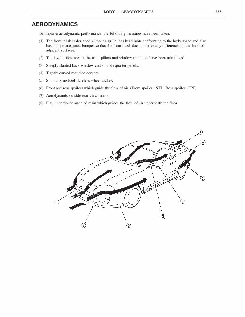
223BODY — AERODYNAMICS
AERODYNAMICS
To improve aerodynamic performance, the following measures have been taken.
(1) The front mask is designed without a grille, has headlights conforming to the body shape and also
has a large integrated bumper so that the front mask does not have any differences in the level of
adjacent surfaces.
(2) The level differences at the front pillars and window moldings have been minimized.
(3) Steeply slanted back window and smooth quarter panels.
(4) Tightly curved rear side corners.
(5) Smoothly molded flareless wheel arches.
(6) Front and rear spoilers which guide the flow of air. (Front spoiler : STD, Rear spoiler: OPT)
(7) Aerodynamic outside rear view mirror.
(8) Flat, undercover made of resin which guides the flow of air underneath the floor.
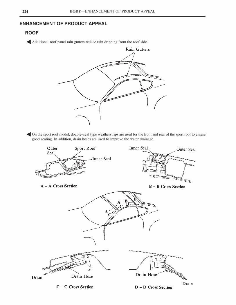
224 BODY—ENHANCEMENT OF PRODUCT APPEAL
ENHANCEMENT OF PRODUCT APPEAL
� ROOF
� Additional roof panel rain gutters reduce rain dripping from the roof side.
� On the sport roof model, double–seal type weatherstrips are used for the front and rear of the sport roof to ensure
good sealing. In addition, drain hoses are used to improve the water drainage.
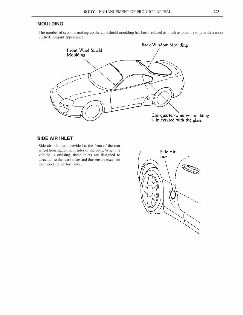
225BODY—ENHANCEMENT OF PRODUCT APPEAL
� MOULDING
The number of sections making up the windshield moulding has been reduced as much as possible to provide a more
unified, elegant appearance.
� SIDE AIR INLET
Side air inlets are provided at the front of the rear
wheel housing, on both sides of the body. When the
vehicle is cruising, these inlets are designed to
direct air to the rear brakes and thus ensure excellent
their cooling performance.
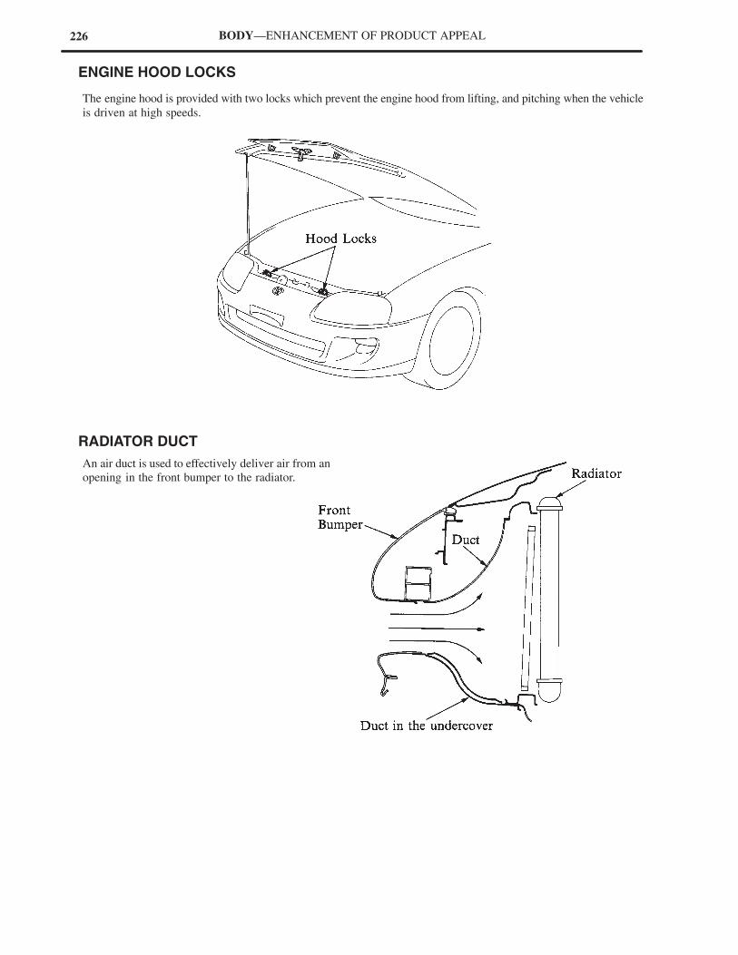
226 BODY—ENHANCEMENT OF PRODUCT APPEAL
� ENGINE HOOD LOCKS
The engine hood is provided with two locks which prevent the engine hood from lifting, and pitching when the vehicle
is driven at high speeds.
� RADIATOR DUCT
An air duct is used to effectively deliver air from an
opening in the front bumper to the radiator.
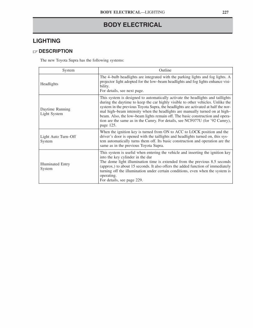
227BODY ELECTRICAL—LIGHTING
BODY ELECTRICAL
LIGHTING
� DESCRIPTION
The new Toyota Supra has the following systems:
System Outline
Headlights
The 4–bulb headlights are integrated with the parking lights and fog lights. Aprojector light adopted for the low–beam headlights and fog lights enhance visi-bility.For details, see next page.
Daytime RunningLight System
This system is designed to automatically activate the headlights and taillightsduring the daytime to keep the car highly visible to other vehicles. Unlike thesystem in the previous Toyota Supra, the headlights are activated at half the nor-mal high–beam intensity when the headlights are manually turned on at high–beam. Also, the low–beam lights remain off. The basic construction and opera-tion are the same as in the Camry. For details, see NCF077U (for ’92 Camry),page 125.
Light Auto Turn–OffSystem
When the ignition key is turned from ON to ACC to LOCK position and thedriver’s door is opened with the taillights and headlights turned on, this sys-tem automatically turns them off. Its basic construction and operation are thesame as in the previous Toyota Supra.
Illuminated Entry System
This system is useful when entering the vehicle and inserting the ignition keyinto the key cylinder in the darThe dome light illumination time is extended from the previous 8.5 seconds(approx.) to about 15 seconds. It also offers the added function of immediatelyturning off the illumination under certain conditions, even when the system isoperating.For details, see page 229.
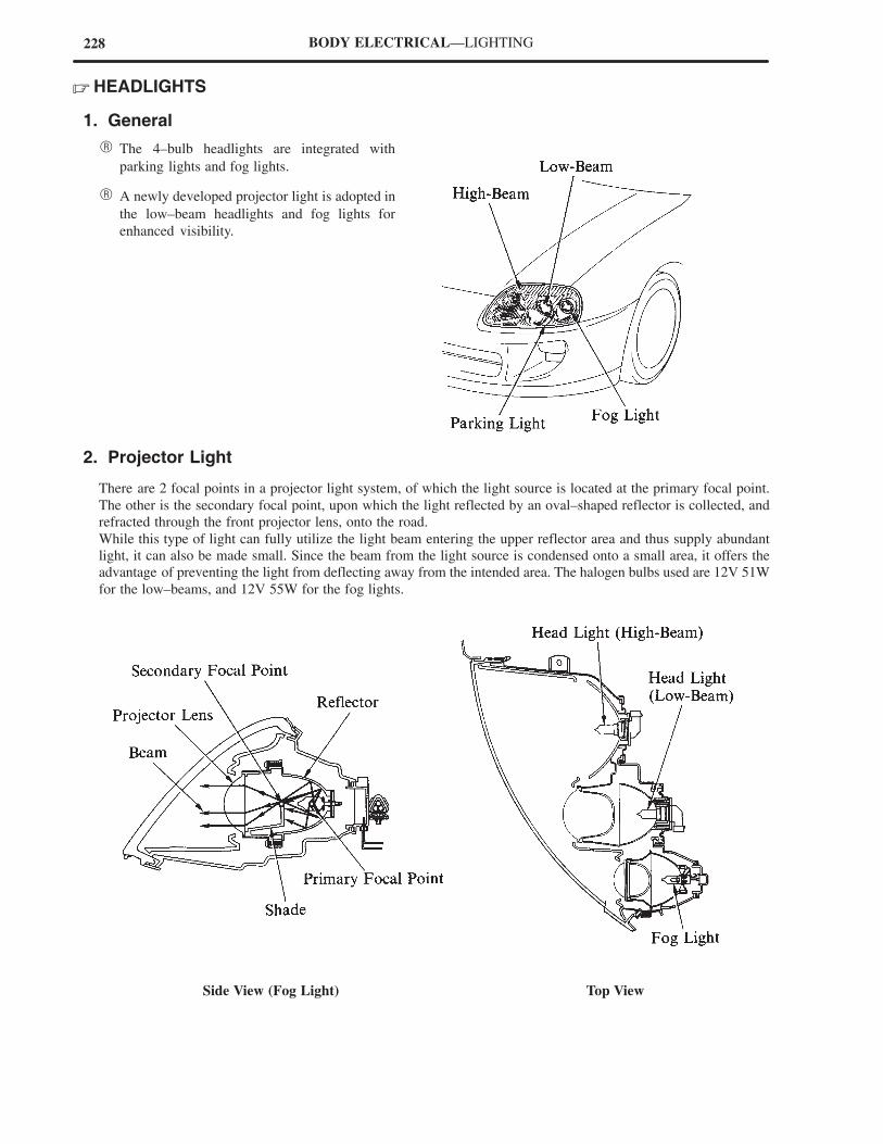
228 BODY ELECTRICAL—LIGHTING
� HEADLIGHTS
1. General
� The 4–bulb headlights are integrated with
parking lights and fog lights.
� A newly developed projector light is adopted in
the low–beam headlights and fog lights for
enhanced visibility.
2. Projector Light
There are 2 focal points in a projector light system, of which the light source is located at the primary focal point.
The other is the secondary focal point, upon which the light reflected by an oval–shaped reflector is collected, and
refracted through the front projector lens, onto the road.
While this type of light can fully utilize the light beam entering the upper reflector area and thus supply abundant
light, it can also be made small. Since the beam from the light source is condensed onto a small area, it offers the
advantage of preventing the light from deflecting away from the intended area. The halogen bulbs used are 12V 51W
for the low–beams, and 12V 55W for the fog lights.
Side View (Fog Light) Top View
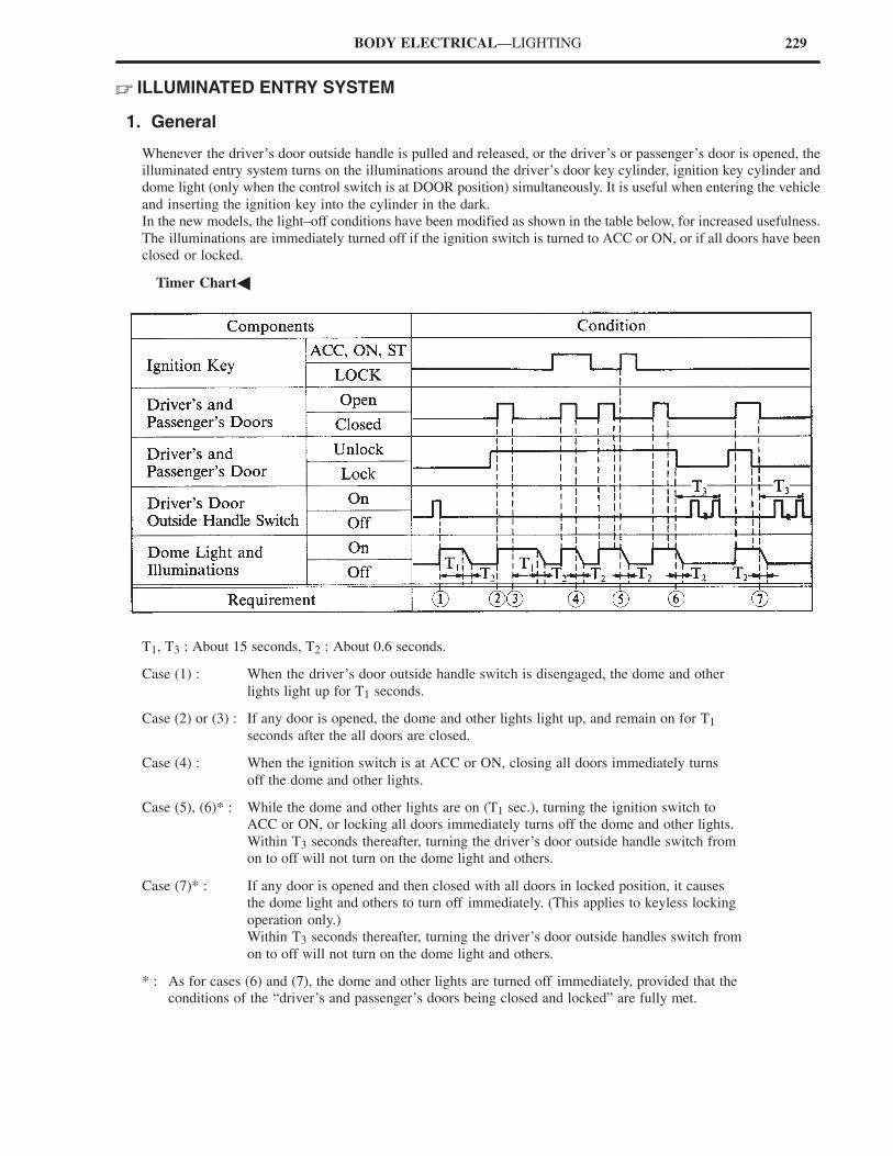
229BODY ELECTRICAL—LIGHTING
� ILLUMINATED ENTRY SYSTEM
1. General
Whenever the driver’s door outside handle is pulled and released, or the driver’s or passenger’s door is opened, the
illuminated entry system turns on the illuminations around the driver’s door key cylinder, ignition key cylinder and
dome light (only when the control switch is at DOOR position) simultaneously. It is useful when entering the vehicle
and inserting the ignition key into the cylinder in the dark.
In the new models, the light–off conditions have been modified as shown in the table below, for increased usefulness.
The illuminations are immediately turned off if the ignition switch is turned to ACC or ON, or if all doors have been
closed or locked.
�Timer Chart�
T1, T3 : About 15 seconds, T2 : About 0.6 seconds.
Case (1) : When the driver’s door outside handle switch is disengaged, the dome and other
lights light up for T1 seconds.
Case (2) or (3) : If any door is opened, the dome and other lights light up, and remain on for T1
seconds after the all doors are closed.
Case (4) : When the ignition switch is at ACC or ON, closing all doors immediately turns
off the dome and other lights.
Case (5), (6)* : While the dome and other lights are on (T1 sec.), turning the ignition switch to
ACC or ON, or locking all doors immediately turns off the dome and other lights.
Within T3 seconds thereafter, turning the driver’s door outside handle switch from
on to off will not turn on the dome light and others.
Case (7)* : If any door is opened and then closed with all doors in locked position, it causes
the dome light and others to turn off immediately. (This applies to keyless locking
operation only.)
Within T3 seconds thereafter, turning the driver’s door outside handles switch from
on to off will not turn on the dome light and others.
* : As for cases (6) and (7), the dome and other lights are turned off immediately, provided that the
conditions of the “driver’s and passenger’s doors being closed and locked” are fully met.
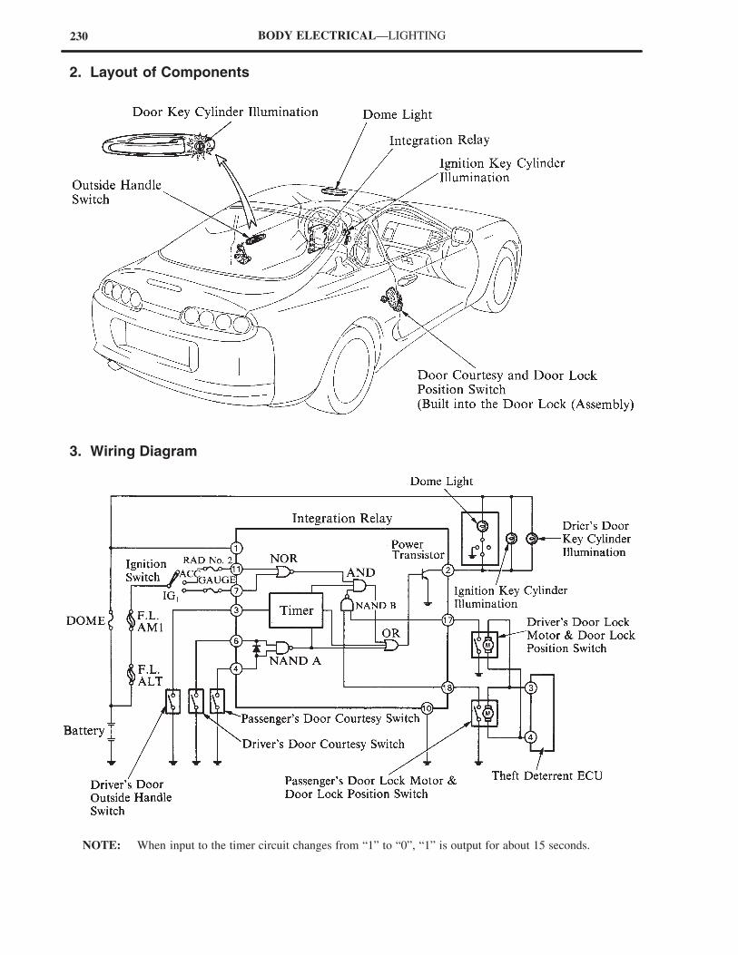
230 BODY ELECTRICAL—LIGHTING
2. Layout of Components
3. Wiring Diagram
NOTE: When input to the timer circuit changes from “1” to “0”, “1” is output for about 15 seconds.
231BODY ELECTRICAL—LIGHTING
4. System Operation
When the Driver’s Door Outside Handle is Pulled and Released
The driver’s door outside handle switch engages when the driver’s door outside handle is pulled and released. Then
the voltage at terminal (3) of the integration relay drops from 0 V to 12 V. This activates the power transistor, which
causes the voltage at terminal (2) to drop from 12 V to 0 V and the illuminations to turn on.
After both doors are locked and the illumination is immediately turned off, the system does not accept any signal input
from the outside handle switch for 15 seconds. Therefore, even if the driver’s door outside handles is operated, it does
not cause the illumination to turn on during that time.
When the Driver’s or Passenger’s Door is Opened
When the driver’s or passenger’s door is opened, the courtesy switch on the respective door goes on. In this way,
terminal (4) or (6) of the integration relay switches from high level (12V) to low level (0V). As a result, the power
transistor is turned on and terminal (2) is switched from high level to low level, turning on the illuminations.
When 15 seconds has Passed Since Bother Doors were Closed
When both doors are closed and terminals (4) and (6) both go high level, the timer circuit operates. The timer keeps
the power transistor on for 15 seconds. After 15 seconds has passed, the illuminations are switched off.
When Both Doors are Closed and the Ignition Key is in a Position other than Lock
When both doors are closed and the ignition key is inserted in the ignition key cylinder and turned to a position other
than LOCK, terminals (4) and (6) both become high level and terminal (7) or (11) switches from low to high level.
As a result, the power transistor goes off and the illuminations are switched off regardless of the operation of the timer
circuit.
When Both Doors are Closed and Both Doors are Locked
When both doors are locked after both doors are closed, or are closed after being locked, terminals (4) and (6) become
high level together and terminals (17) and (18) switch from low to high level. As result, the power transistor goes
off and the illuminations are switched off regardless of the operation of the timer circuit.
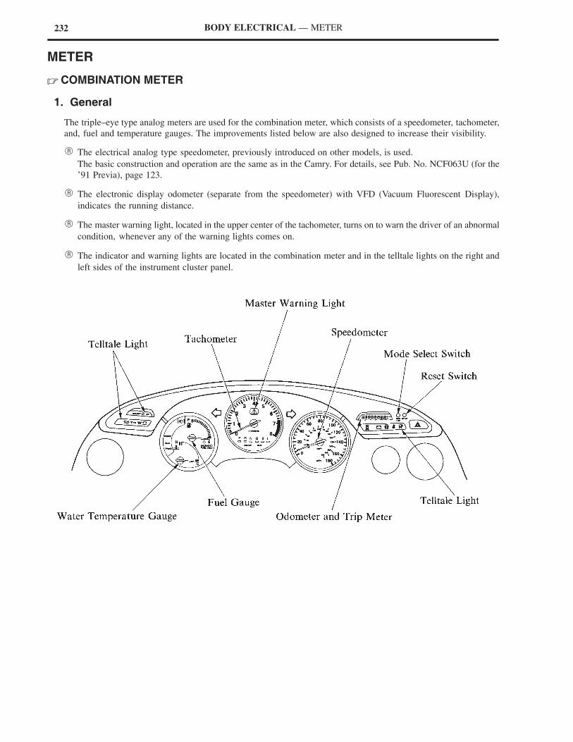
232 BODY ELECTRICAL — METER
METER
� COMBINATION METER
1. General
The triple–eye type analog meters are used for the combination meter, which consists of a speedometer, tachometer,
and, fuel and temperature gauges. The improvements listed below are also designed to increase their visibility.
� The electrical analog type speedometer, previously introduced on other models, is used.
The basic construction and operation are the same as in the Camry. For details, see Pub. No. NCF063U (for the
’91 Previa), page 123.
� The electronic display odometer (separate from the speedometer) with VFD (Vacuum Fluorescent Display),
indicates the running distance.
� The master warning light, located in the upper center of the tachometer, turns on to warn the driver of an abnormal
condition, whenever any of the warning lights comes on.
� The indicator and warning lights are located in the combination meter and in the telltale lights on the right and
left sides of the instrument cluster panel.
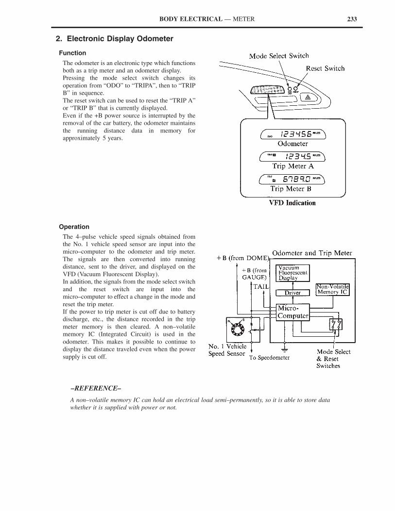
233
A non–volatile memory IC can hold an electrical load semi–permanently, so it is able to store data
whether it is supplied with power or not.
–REFERENCE–
BODY ELECTRICAL — METER
2. Electronic Display Odometer
Function
The odometer is an electronic type which functions
both as a trip meter and an odometer display.
Pressing the mode select switch changes its
operation from “ODO” to “TRIPA”, then to “TRIP
B” in sequence.
The reset switch can be used to reset the “TRIP A”
or “TRIP B” that is currently displayed.
Even if the +B power source is interrupted by the
removal of the car battery, the odometer maintains
the running distance data in memory for
approximately 5 years.
Operation
The 4–pulse vehicle speed signals obtained from
the No. 1 vehicle speed sensor are input into the
micro–computer to the odometer and trip meter.
The signals are then converted into running
distance, sent to the driver, and displayed on the
VFD (Vacuum Fluorescent Display).
In addition, the signals from the mode select switch
and the reset switch are input into the
micro–computer to effect a change in the mode and
reset the trip meter.
If the power to trip meter is cut off due to battery
discharge, etc., the distance recorded in the trip
meter memory is then cleared. A non–volatile
memory IC (Integrated Circuit) is used in the
odometer. This makes it possible to continue to
display the distance traveled even when the power
supply is cut off.
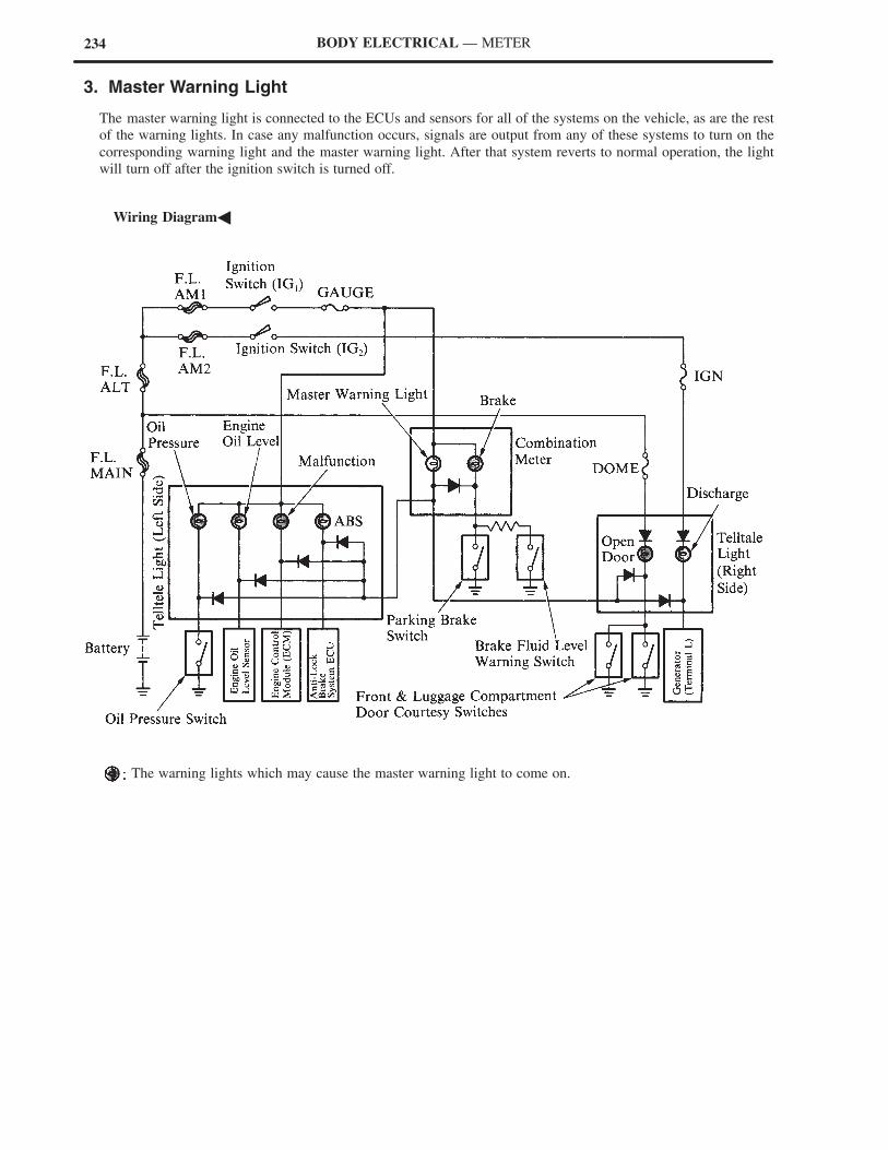
234 BODY ELECTRICAL — METER
3. Master Warning Light
The master warning light is connected to the ECUs and sensors for all of the systems on the vehicle, as are the rest
of the warning lights. In case any malfunction occurs, signals are output from any of these systems to turn on the
corresponding warning light and the master warning light. After that system reverts to normal operation, the light
will turn off after the ignition switch is turned off.
�Wiring Diagram�
The warning lights which may cause the master warning light to come on.
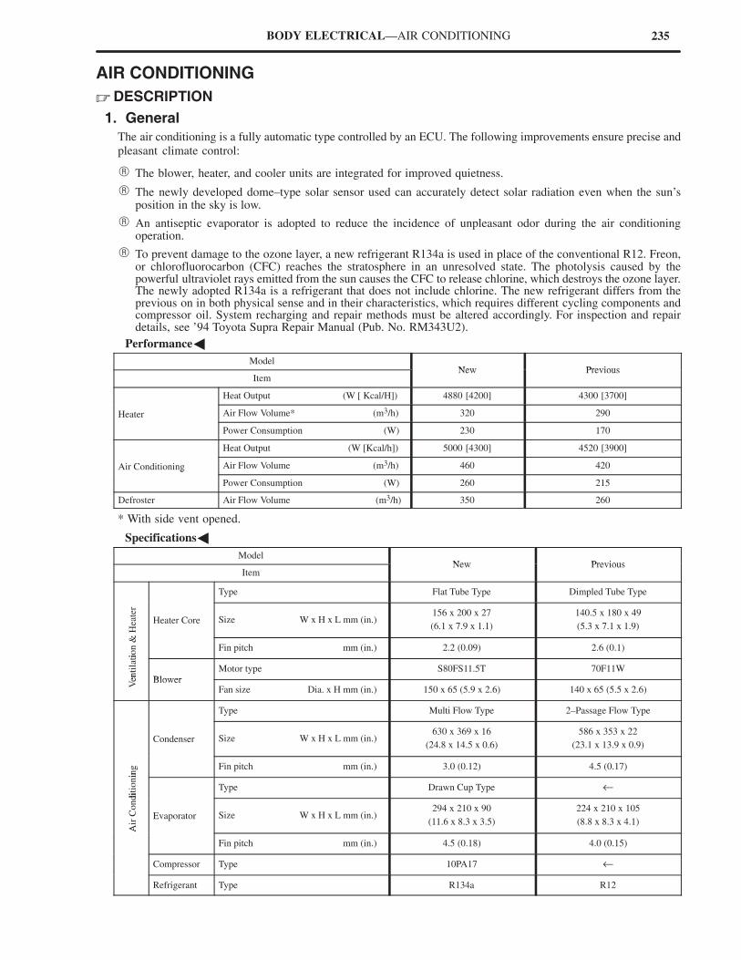
235BODY ELECTRICAL—AIR CONDITIONING
AIR CONDITIONING
� DESCRIPTION
1. General
The air conditioning is a fully automatic type controlled by an ECU. The following improvements ensure precise and
pleasant climate control:
� The blower, heater, and cooler units are integrated for improved quietness.
� The newly developed dome–type solar sensor used can accurately detect solar radiation even when the sun’sposition in the sky is low.
� An antiseptic evaporator is adopted to reduce the incidence of unpleasant odor during the air conditioningoperation.
� To prevent damage to the ozone layer, a new refrigerant R134a is used in place of the conventional R12. Freon,or chlorofluorocarbon (CFC) reaches the stratosphere in an unresolved state. The photolysis caused by thepowerful ultraviolet rays emitted from the sun causes the CFC to release chlorine, which destroys the ozone layer.The newly adopted R134a is a refrigerant that does not include chlorine. The new refrigerant differs from theprevious on in both physical sense and in their characteristics, which requires different cycling components andcompressor oil. System recharging and repair methods must be altered accordingly. For inspection and repairdetails, see ’94 Toyota Supra Repair Manual (Pub. No. RM343U2).
�Performance�
ModelNew Previous
ItemNew Previous
Heat Output (W [ Kcal/H]) 4880 [4200] 4300 [3700]
Heater Air Flow Volume* (m3/h) 320 290
Power Consumption (W) 230 170
Heat Output (W [Kcal/h]) 5000 [4300] 4520 [3900]
Air Conditioning Air Flow Volume (m3/h) 460 420g
Power Consumption (W) 260 215
Defroster Air Flow Volume (m3/h) 350 260
* With side vent opened.
�Specifications�
ModelNew Previous
ItemNew Previous
Type Flat Tube Type Dimpled Tube Type
& H
eate
r
Heater Core Size W x H x L mm (in.)156 x 200 x 27
(6.1 x 7.9 x 1.1)
140.5 x 180 x 49
(5.3 x 7.1 x 1.9)
tion &
Fin pitch mm (in.) 2.2 (0.09) 2.6 (0.1)
enti
lati
o
Blower
Motor type S80FS11.5T 70F11W
Ven Blower
Fan size Dia. x H mm (in.) 150 x 65 (5.9 x 2.6) 140 x 65 (5.5 x 2.6)
Type Multi Flow Type 2–Passage Flow Type
Condenser Size W x H x L mm (in.)630 x 369 x 16
(24.8 x 14.5 x 0.6)
586 x 353 x 22
(23.1 x 13.9 x 0.9)
ing Fin pitch mm (in.) 3.0 (0.12) 4.5 (0.17)
dit
ionin
Type Drawn Cup Type ←
Air
Condi
Evaporator Size W x H x L mm (in.)294 x 210 x 90
(11.6 x 8.3 x 3.5)
224 x 210 x 105
(8.8 x 8.3 x 4.1)
A
Fin pitch mm (in.) 4.5 (0.18) 4.0 (0.15)
Compressor Type 10PA17 ←
Refrigerant Type R134a R12
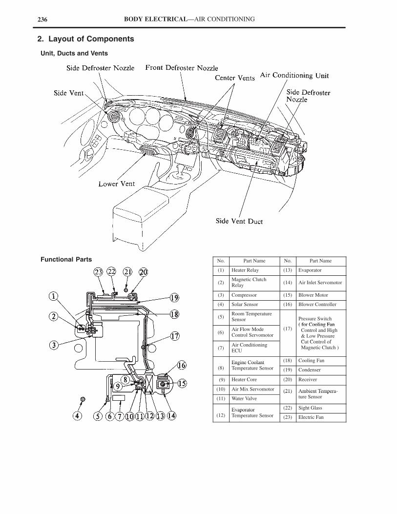
236 BODY ELECTRICAL—AIR CONDITIONING
2. Layout of Components
Unit, Ducts and Vents
Functional Parts No. Part Name No. Part Name
(1) Heater Relay (13) Evaporator
(2)Magnetic ClutchRelay
(14) Air Inlet Servomotor
(3) Compressor (15) Blower Motor
(4) Solar Sensor (16) Blower Controller
(5)Room TemperatureSensor Pressure Switch
( for Cooling Fan
(6)Air Flow ModeControl Servomotor
(17)( for Cooling Fan Control and High & Low PressureC t C t l f
(7)Air ConditioningECU
Cut Control of Magnetic Clutch )
Engine Coolant (18) Cooling Fan
(8)Engine CoolantTemperature Sensor (19) Condenser
(9) Heater Core (20) Receiver
(10) Air Mix Servomotor (21) Ambient Tempera-
(11) Water Valve
(21) Ambient Temperature Sensor
Evaporator (22) Sight Glass
(12)EvaporatorTemperature Sensor (23) Electric Fan
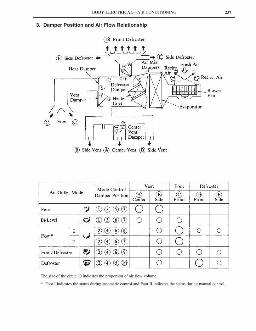
237BODY ELECTRICAL—AIR CONDITIONING
3. Damper Position and Air Flow Relationship
The size of the circle � indicates the proportion of air flow volume.
* Foot I indicates the status during automatic control and Foot II indicates the status during manual control.
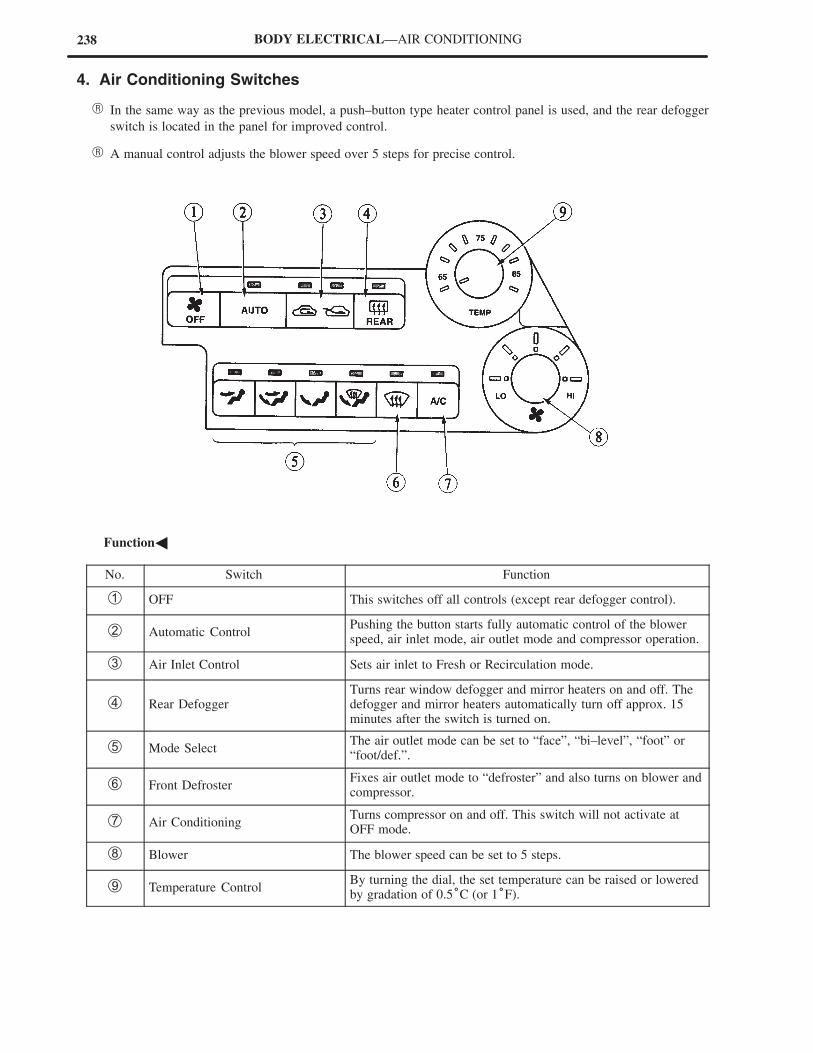
238 BODY ELECTRICAL—AIR CONDITIONING
4. Air Conditioning Switches
� In the same way as the previous model, a push–button type heater control panel is used, and the rear defogger
switch is located in the panel for improved control.
� A manual control adjusts the blower speed over 5 steps for precise control.
�Function�
No. Switch Function
� OFF This switches off all controls (except rear defogger control).
� Automatic ControlPushing the button starts fully automatic control of the blowerspeed, air inlet mode, air outlet mode and compressor operation.
� Air Inlet Control Sets air inlet to Fresh or Recirculation mode.
� Rear DefoggerTurns rear window defogger and mirror heaters on and off. Thedefogger and mirror heaters automatically turn off approx. 15minutes after the switch is turned on.
� Mode SelectThe air outlet mode can be set to “face”, “bi–level”, “foot” or“foot/def.”.
� Front DefrosterFixes air outlet mode to “defroster” and also turns on blower andcompressor.
� Air ConditioningTurns compressor on and off. This switch will not activate atOFF mode.
� Blower The blower speed can be set to 5 steps.
Temperature ControlBy turning the dial, the set temperature can be raised or loweredby gradation of 0.5°C (or 1°F).
239BODY ELECTRICAL—AIR CONDITIONING
1. Air Condition Unit
The air conditioning unit incorporates a blower, heater and cooler units. This provides high rigidity and low
ventilating resistance, and improve quietness and performance.
Blower Fan
The blower fan is large to ensure a large air flow volume (Diameter: 150mm [5.91 in.]).
Heater Core
Made of aluminum, lightweight, and with a large capacity, it offers good heat radiation efficiency.
Evaporator
This is the same type of drawn cup type evaporator,
with high heat exchange efficiency, which is used in
the previous model.
In addition, the nylon coating of the evaporator
surface contains antiseptic agent to prevent the
propagation of germs which can cause bad odors.
240 BODY ELECTRICAL—AIR CONDITIONING
Air Fan Control Dampers
The air flow made and proportions of air flow volume are adjusted by 6 dampers.
Blower Controller
Signals from the air conditioning ECU are input into the blower controller. Then, the electrical current of the signals
is modified by the signal–processing circuit of the blower controller, and the blower motor speed and rotation are
regulated by the drive circuit.
Servomotors
In the same way as the previous model, the airflow control positions are changed by 3 servomotors.
In the new model, the servomotors are made smaller and lighter.
2. CondenserBy changing from the 2–passage flow type to the
multi–flow type condenser, a wider heat dissipation
area is obtained, thus improving its
heat–exchanging efficiency.
3. Solar Sensor
A dome–type solar sensor, which detects solar radiation by way of a photo diode, is used.
The dome–type’s sensitivity to overhead light source is lowered, and its diagonal sensitivity difference, the sensor
improves the auto air–conditioning control capabilities.
4. Front Defroster Nozzle
The front defroster nozzle inner wall is modified into a radial configuration for a smoother air flow. The defroster
performance is thus improved and the blower noise in the defroster mode is reduced.
New Previous
241BODY ELECTRICAL—AIR CONDITIONING
5. Air Conditioning ECU
� The air conditioning ECU, attached to the upper part of the audio unit in the instrument panel, has full automatic
control over the air conditioning. This system automatically regulates the servomotors and blower motor to
deliver the required outlet air temperature in accordance with the set temperature.
� The self–diagnosis system used can be controlled and displayed on the heater control panel.
Details on the main system and their functions are illustrated below.
Calculation of Required Outlet Air Temperature
After receiving the signals from the sensors and the temperature control switch setting, the air conditioning ECU uses
the formula shown below to calculate the required outlet air temperature, to regulate the servomotors and blower
motor. This is an outlet air temperature that is required in maintaining the set temperature in a stable manner.
Temperature Control System
1) Air Mix Damper Control
In response to the temperature control switch setting, the required outlet air temperature, evaporator temperature
sensor, and engine coolant temperature sensor compensations are used by the air mix damper control to calculate
a tentative damper opening angle, through an arithmetic circuit in the air mix damper, to arrive at a target damper
opening. If the difference between the target damper opening and the actual opening is 4% or more, the air mix
damper control regulates the servomotor to reduce that difference to 3% or less.
�Calculating the target damper opening� �Air Mix servomotor control�
242 BODY ELECTRICAL—AIR CONDITIONING
Blower Control System
1) Blower motor startup control
When the blower motor is started up, the blower voltage in the auto mode (low speed) is output to the blower
controller for 3 seconds. This is designed to protect the blower controller from a sudden startup voltage surge.
2) Manual Control
Sets the blower speed according to operation of the blower switch (5–steps)
3) Automatic Control
a. Stepless Air Volume Control
As shown on the right, when the AUTO switch
on the heater control panel is pushed, the air
conditioning ECU automatically regulates the
voltage to the blower controller, in accordance
with the required outlet air temperature, to
deliver stepless air volume.
b. Warm–Up Control
When the coolant temperature detected by the engine coolant temperature sensor is below a predetermined level
and the air outlet is in the FOOT or BI–LEVEL mode, the blower does not operate. When the coolant
temperature reaches 35°C (95°F), the blower motor operates at low speed. When the coolant temperature is
between 35 to 60°C (95 to 140°F), the air flow calculation using the engine coolant temperature sensor signal,
and, the air flow calculation using the required outlet air temperature are compared, and the lesser or the two
is automatically selected as the air flow to be used. When the coolant temperature reaches 60°C (140°F) or
more, the blower motor runs at high speed. Moreover, when the coolant temperature is under 32°C (89.6°F),
and the warm–up control is effected (blower motor off), the air outlet is switched to the DEF mode. Later, when
the blower motor turns on, the air outlet changes from the DEF mode to the FOOT or BI–LEVEL mode.
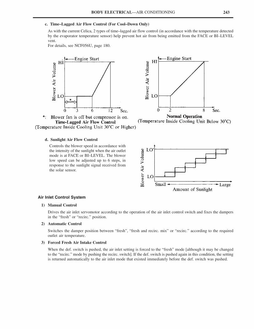
243BODY ELECTRICAL—AIR CONDITIONING
c. Time–Lagged Air Flow Control (For Cool–Down Only)
As with the current Celica, 2 types of time–lagged air flow control (in accordance with the temperature detected
by the evaporator temperature sensor) help prevent hot air from being emitted from the FACE or BI–LEVEL
vent.
For details, see NCF056U, page 180.
d. Sunlight Air Flow Control
Controls the blower speed in accordance with
the intensity of the sunlight when the air outlet
mode is at FACE or BI–LEVEL. The blower
low speed can be adjusted up to 6 steps, in
response to the sunlight signal received from
the solar sensor.
Air Inlet Control System
1) Manual Control
Drives the air inlet servomotor according to the operation of the air inlet control switch and fixes the dampers
in the “fresh” or “recirc.” position.
2) Automatic Control
Switches the damper position between “fresh”, “fresh and recirc. mix” or “recirc.” according to the required
outlet air temperature.
3) Forced Fresh Air Intake Control
When the def. switch is pushed, the air inlet setting is forced to the “fresh” mode [although it may be changed
to the “recirc.” mode by pushing the recirc. switch]. If the def. switch is pushed again in this condition, the setting
is returned automatically to the air inlet mode that existed immediately before the def. switch was pushed.
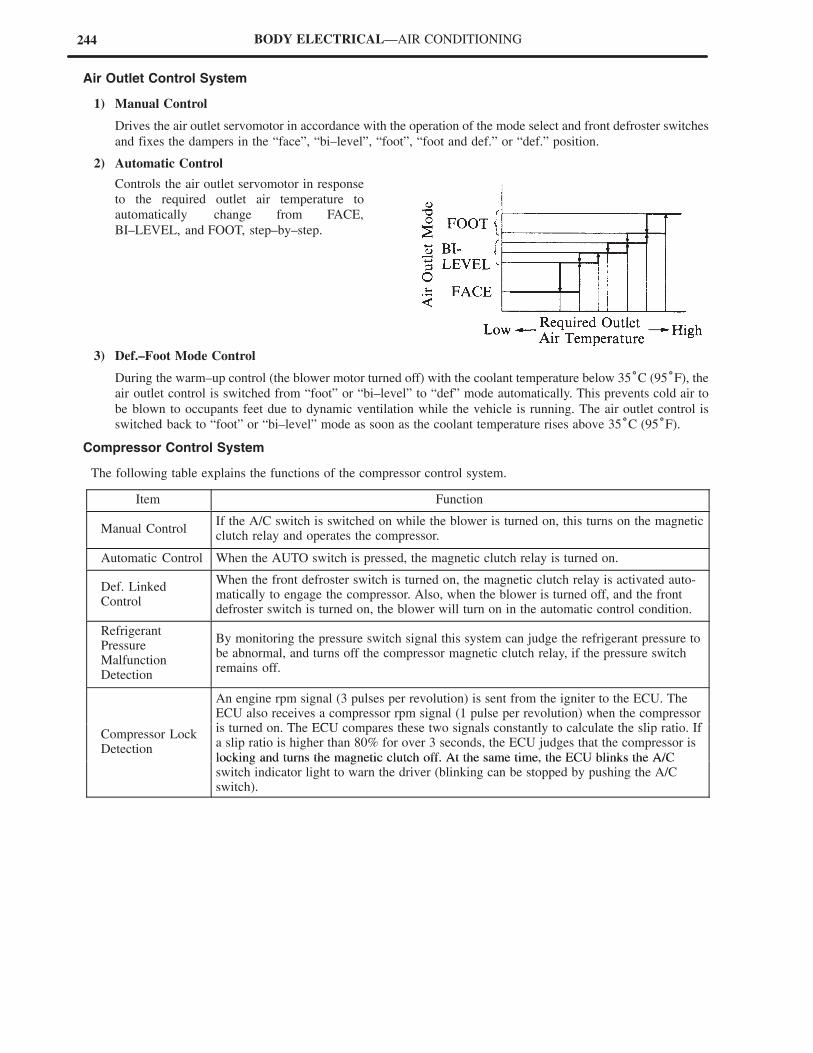
244 BODY ELECTRICAL—AIR CONDITIONING
Air Outlet Control System
1) Manual Control
Drives the air outlet servomotor in accordance with the operation of the mode select and front defroster switches
and fixes the dampers in the “face”, “bi–level”, “foot”, “foot and def.” or “def.” position.
2) Automatic Control
Controls the air outlet servomotor in response
to the required outlet air temperature to
automatically change from FACE,
BI–LEVEL, and FOOT, step–by–step.
3) Def.–Foot Mode Control
During the warm–up control (the blower motor turned off) with the coolant temperature below 35°C (95°F), the
air outlet control is switched from “foot” or “bi–level” to “def” mode automatically. This prevents cold air to
be blown to occupants feet due to dynamic ventilation while the vehicle is running. The air outlet control is
switched back to “foot” or “bi–level” mode as soon as the coolant temperature rises above 35°C (95°F).
Compressor Control System
The following table explains the functions of the compressor control system.
Item Function
Manual ControlIf the A/C switch is switched on while the blower is turned on, this turns on the magneticclutch relay and operates the compressor.
Automatic Control When the AUTO switch is pressed, the magnetic clutch relay is turned on.
Def. LinkedControl
When the front defroster switch is turned on, the magnetic clutch relay is activated auto-matically to engage the compressor. Also, when the blower is turned off, and the frontdefroster switch is turned on, the blower will turn on in the automatic control condition.
RefrigerantPressureMalfunctionDetection
By monitoring the pressure switch signal this system can judge the refrigerant pressure tobe abnormal, and turns off the compressor magnetic clutch relay, if the pressure switchremains off.
An engine rpm signal (3 pulses per revolution) is sent from the igniter to the ECU. TheECU also receives a compressor rpm signal (1 pulse per revolution) when the compressori d Th ECU h i l l l l h li i If
Compressor LockDetection
p p g p p pis turned on. The ECU compares these two signals constantly to calculate the slip ratio. Ifa slip ratio is higher than 80% for over 3 seconds, the ECU judges that the compressor islocking and turns the magnetic clutch off. At the same time, the ECU blinks the A/Clocking and turns the magnetic clutch off. At the same time, the ECU blinks the A/Cswitch indicator light to warn the driver (blinking can be stopped by pushing the A/Cswitch).
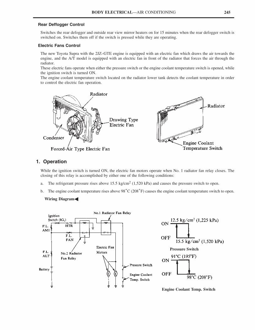
245BODY ELECTRICAL—AIR CONDITIONING
Rear Deffogger Control
Switches the rear defogger and outside rear view mirror heaters on for 15 minutes when the rear defogger switch is
switched on. Switches them off if the switch is pressed while they are operating.
Electric Fans Control
The new Toyota Supra with the 2JZ–GTE engine is equipped with an electric fan which draws the air towards the
engine, and the A/T model is equipped with an electric fan in front of the radiator that forces the air through the
radiator.
These electric fans operate when either the pressure switch or the engine coolant temperature switch is opened, while
the ignition switch is turned ON.
The engine coolant temperature switch located on the radiator lower tank detects the coolant temperature in order
to control the electric fan operation.
1. Operation
While the ignition switch is turned ON, the electric fan motors operate when No. 1 radiator fan relay closes. The
closing of this relay is accomplished by either one of the following conditions:
a. The refrigerant pressure rises above 15.5 kg/cm2 (1,520 kPa) and causes the pressure switch to open.
b. The engine coolant temperature rises above 98°C (208°F) causes the engine coolant temperature switch to open.
�Wiring Diagram�
Engine Coolant Temp. Switch
Pressure Switch
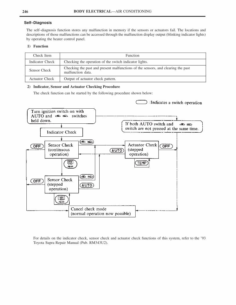
246 BODY ELECTRICAL—AIR CONDITIONING
Self–Diagnosis
The self–diagnosis function stores any malfunction in memory if the sensors or actuators fail. The locations and
descriptions of those malfunctions can be accessed through the malfunction display output (blinking indicator lights)
by operating the heater control panel.
1) Function
Check Item Function
Indicator Check Checking the operation of the switch indicator lights.
Sensor CheckChecking the past and present malfunctions of the sensors, and clearing the pastmalfunction data.
Actuator Check Output of actuator check pattern.
2) Indicator, Sensor and Actuator Checking Procedure
The check function can be started by the following procedure shown below:
For details on the indicator check, sensor check and actuator check functions of this system, refer to the ’93
Toyota Supra Repair Manual (Pub. RM343U2).
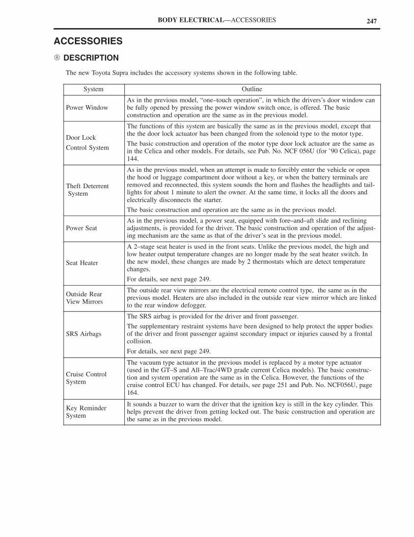
247BODY ELECTRICAL—ACCESSORIES
ACCESSORIES
� DESCRIPTION
The new Toyota Supra includes the accessory systems shown in the following table.
System Outline
Power WindowAs in the previous model, “one–touch operation”, in which the drivers’s door window canbe fully opened by pressing the power window switch once, is offered. The basicconstruction and operation are the same as in the previous model.
Door Lock
Control System
The functions of this system are basically the same as in the previous model, except thatthe the door lock actuator has been changed from the solenoid type to the motor type.
The basic construction and operation of the motor type door lock actuator are the same asin the Celica and other models. For details, see Pub. No. NCF 056U (for ’90 Celica), page144.
Theft Deterrent System
As in the previous model, when an attempt is made to forcibly enter the vehicle or openthe hood or luggage compartment door without a key, or when the battery terminals areremoved and reconnected, this system sounds the horn and flashes the headlights and tail-lights for about 1 minute to alert the owner. At the same time, it locks all the doors andelectrically disconnects the starter.
The basic construction and operation are the same as in the previous model.
Power SeatAs in the previous model, a power seat, equipped with fore–and–aft slide and recliningadjustments, is provided for the driver. The basic construction and operation of the adjust-ing mechanism are the same as that of the driver’s seat in the previous model.
Seat Heater
A 2–stage seat heater is used in the front seats. Unlike the previous model, the high andlow heater output temperature changes are no longer made by the seat heater switch. Inthe new model, these changes are made by 2 thermostats which are detect temperaturechanges.
For details, see next page 249.
Outside RearView Mirrors
The outside rear view mirrors are the electrical remote control type, the same as in theprevious model. Heaters are also included in the outside rear view mirror which are linkedto the rear window defogger.
SRS Airbags
The SRS airbag is provided for the driver and front passenger.
The supplementary restraint systems have been designed to help protect the upper bodiesof the driver and front passenger against secondary impact or injuries caused by a frontalcollision.
For details, see next page 249.
Cruise ControlSystem
The vacuum type actuator in the previous model is replaced by a motor type actuator(used in the GT–S and All–Trac/4WD grade current Celica models). The basic construc-tion and system operation are the same as in the Celica. However, the functions of thecruise control ECU has changed. For details, see page 251 and Pub. No. NCF056U, page164.
Key ReminderSystem
It sounds a buzzer to warn the driver that the ignition key is still in the key cylinder. Thishelps prevent the driver from getting locked out. The basic construction and operation arethe same as in the previous model.

248 BODY ELECTRICAL—ACCESSORIES
� SEAT HEATER
1. General
As shown on the right, the seat heater has 2 separate
heating element circuits, A and B. It also contains
2 thermostats which automatically direct the heat
output to high or low.
2. Wiring Diagram and Operation
When the seat heater switch is turned on, the seat heater relay is activated, and applies current to heating elements
A and B to quickly (high operation) warm up the seat. Once the seat temperature rises, and the surface temperature
of the thermostats A and B reaches approximately 40°C (104°F), the thermostats A and B are turned off, disrupting
the current flow to the heating element A. Accordingly, the seat is warned only by the heating element B, generating
a low heat output. When the seat temperature drops, and the the surface temperature of the thermostats A and B
reaches approximately 30° C (86(°F), the thermostats A and B are turned on, applying current to the heating element
A.
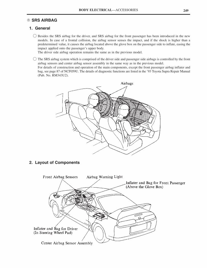
249BODY ELECTRICAL—ACCESSORIES
� SRS AIRBAG
1. General
� Besides the SRS airbag for the driver, and SRS airbag for the front passenger has been introduced in the new
models. In case of a frontal collision, the airbag sensor senses the impact, and if the shock is higher than a
predetermined value, it causes the airbag located above the glove box on the passenger side to inflate, easing the
impact applied onto the passenger’s upper body.
The driver side airbag operation remains the same as in the previous model.
� The SRS airbag system which is comprised of the driver side and passenger side airbags is controlled by the front
airbag sensors and center airbag sensor assembly in the same way as in the previous model.
For details of construction and operation of the main components, except the front passenger airbag inflater and
bag, see page 87 of NCF059U. The details of diagnostic functions are listed in the ’93 Toyota Supra Repair Manual
(Pub. No. RM343U2).
2. Layout of Components
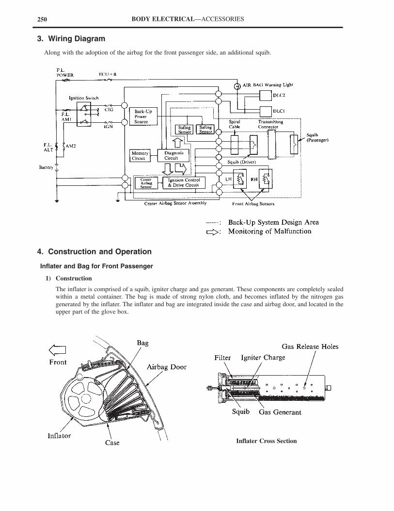
250 BODY ELECTRICAL—ACCESSORIES
3. Wiring Diagram
Along with the adoption of the airbag for the front passenger side, an additional squib.
4. Construction and Operation
Inflater and Bag for Front Passenger
1) Construction
The inflater is comprised of a squib, igniter charge and gas generant. These components are completely sealed
within a metal container. The bag is made of strong nylon cloth, and becomes inflated by the nitrogen gas
generated by the inflater. The inflater and bag are integrated inside the case and airbag door, and located in the
upper part of the glove box.
Inflater Cross Section
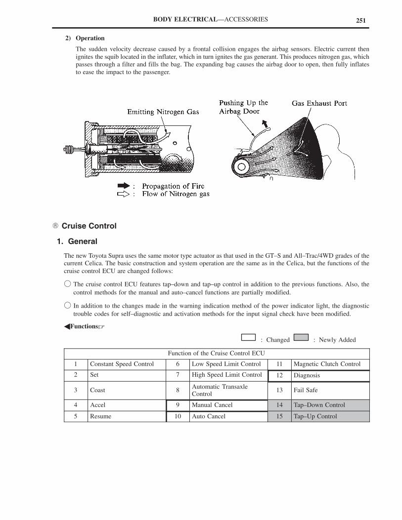
251BODY ELECTRICAL—ACCESSORIES
2) Operation
The sudden velocity decrease caused by a frontal collision engages the airbag sensors. Electric current then
ignites the squib located in the inflater, which in turn ignites the gas generant. This produces nitrogen gas, which
passes through a filter and fills the bag. The expanding bag causes the airbag door to open, then fully inflates
to ease the impact to the passenger.
� Cruise Control
1. General
The new Toyota Supra uses the same motor type actuator as that used in the GT–S and All–Trac/4WD grades of the
current Celica. The basic construction and system operation are the same as in the Celica, but the functions of the
cruise control ECU are changed follows:
� The cruise control ECU features tap–down and tap–up control in addition to the previous functions. Also, the
control methods for the manual and auto–cancel functions are partially modified.
� In addition to the changes made in the warning indication method of the power indicator light, the diagnostic
trouble codes for self–diagnostic and activation methods for the input signal check have been modified.
�Functions�
: Changed : Newly Added
Function of the Cruise Control ECU
1 Constant Speed Control 6 Low Speed Limit Control 11 Magnetic Clutch Control
2 Set 7 High Speed Limit Control 12 Diagnosis
3 Coast 8Automatic TransaxleControl
13 Fail Safe
4 Accel 9 Manual Cancel 14 Tap–Down Control
5 Resume 10 Auto Cancel 15 Tap–Up Control
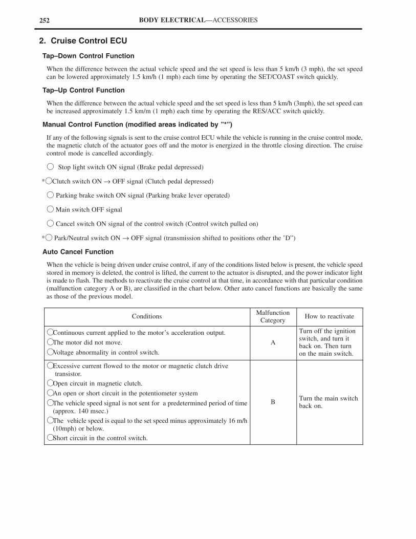
252 BODY ELECTRICAL—ACCESSORIES
2. Cruise Control ECU
Tap–Down Control Function
When the difference between the actual vehicle speed and the set speed is less than 5 km/h (3 mph), the set speed
can be lowered approximately 1.5 km/h (1 mph) each time by operating the SET/COAST switch quickly.
Tap–Up Control Function
When the difference between the actual vehicle speed and the set speed is less than 5 km/h (3mph), the set speed can
be increased approximately 1.5 km/m (1 mph) each time by operating the RES/ACC switch quickly.
Manual Control Function (modified areas indicated by ”*”)
If any of the following signals is sent to the cruise control ECU while the vehicle is running in the cruise control mode,
the magnetic clutch of the actuator goes off and the motor is energized in the throttle closing direction. The cruise
control mode is cancelled accordingly.
� Stop light switch ON signal (Brake pedal depressed)
*� Clutch switch ON → OFF signal (Clutch pedal depressed)
� Parking brake switch ON signal (Parking brake lever operated)
� Main switch OFF signal
� Cancel switch ON signal of the control switch (Control switch pulled on)
*� Park/Neutral switch ON → OFF signal (transmission shifted to positions other the ’D”)
Auto Cancel Function
When the vehicle is being driven under cruise control, if any of the conditions listed below is present, the vehicle speed
stored in memory is deleted, the control is lifted, the current to the actuator is disrupted, and the power indicator light
is made to flash. The methods to reactivate the cruise control at that time, in accordance with that particular condition
(malfunction category A or B), are classified in the chart below. Other auto cancel functions are basically the same
as those of the previous model.
ConditionsMalfunction
CategoryHow to reactivate
�Continuous current applied to the motor’s acceleration output.
�The motor did not move.
�Voltage abnormality in control switch.
A
Turn off the ignitionswitch, and turn itback on. Then turnon the main switch.
�Excessive current flowed to the motor or magnetic clutch drive
transistor.
�Open circuit in magnetic clutch.
�An open or short circuit in the potentiometer system
�The vehicle speed signal is not sent for a predetermined period of time
(approx. 140 msec.)
�The vehicle speed is equal to the set speed minus approximately 16 m/h
(10mph) or below.
�Short circuit in the control switch.
BTurn the main switchback on.
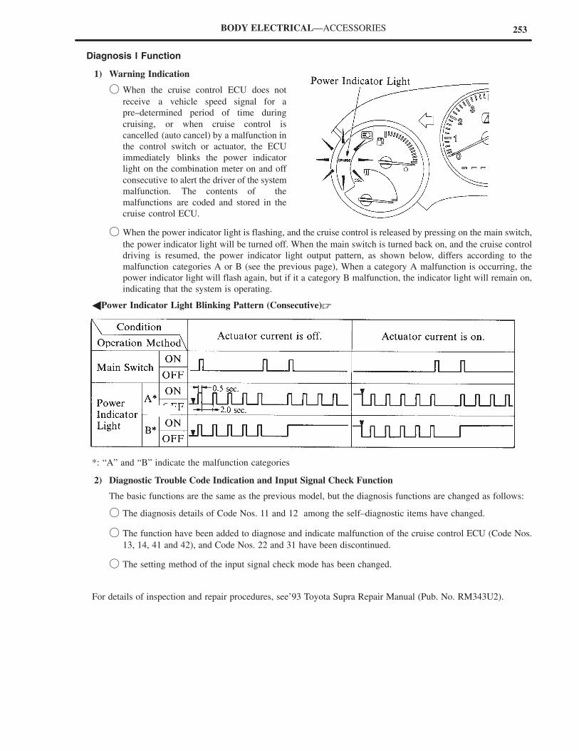
253BODY ELECTRICAL—ACCESSORIES
Diagnosis l Function
1) Warning Indication
� When the cruise control ECU does not
receive a vehicle speed signal for a
pre–determined period of time during
cruising, or when cruise control is
cancelled (auto cancel) by a malfunction in
the control switch or actuator, the ECU
immediately blinks the power indicator
light on the combination meter on and off
consecutive to alert the driver of the system
malfunction. The contents of the
malfunctions are coded and stored in the
cruise control ECU.
� When the power indicator light is flashing, and the cruise control is released by pressing on the main switch,
the power indicator light will be turned off. When the main switch is turned back on, and the cruise control
driving is resumed, the power indicator light output pattern, as shown below, differs according to the
malfunction categories A or B (see the previous page), When a category A malfunction is occurring, the
power indicator light will flash again, but if it a category B malfunction, the indicator light will remain on,
indicating that the system is operating.
�Power Indicator Light Blinking Pattern (Consecutive)�
*: “A” and “B” indicate the malfunction categories
2) Diagnostic Trouble Code Indication and Input Signal Check Function
The basic functions are the same as the previous model, but the diagnosis functions are changed as follows:
� The diagnosis details of Code Nos. 11 and 12 among the self–diagnostic items have changed.
� The function have been added to diagnose and indicate malfunction of the cruise control ECU (Code Nos.
13, 14, 41 and 42), and Code Nos. 22 and 31 have been discontinued.
� The setting method of the input signal check mode has been changed.
For details of inspection and repair procedures, see’93 Toyota Supra Repair Manual (Pub. No. RM343U2).

4. Appendix
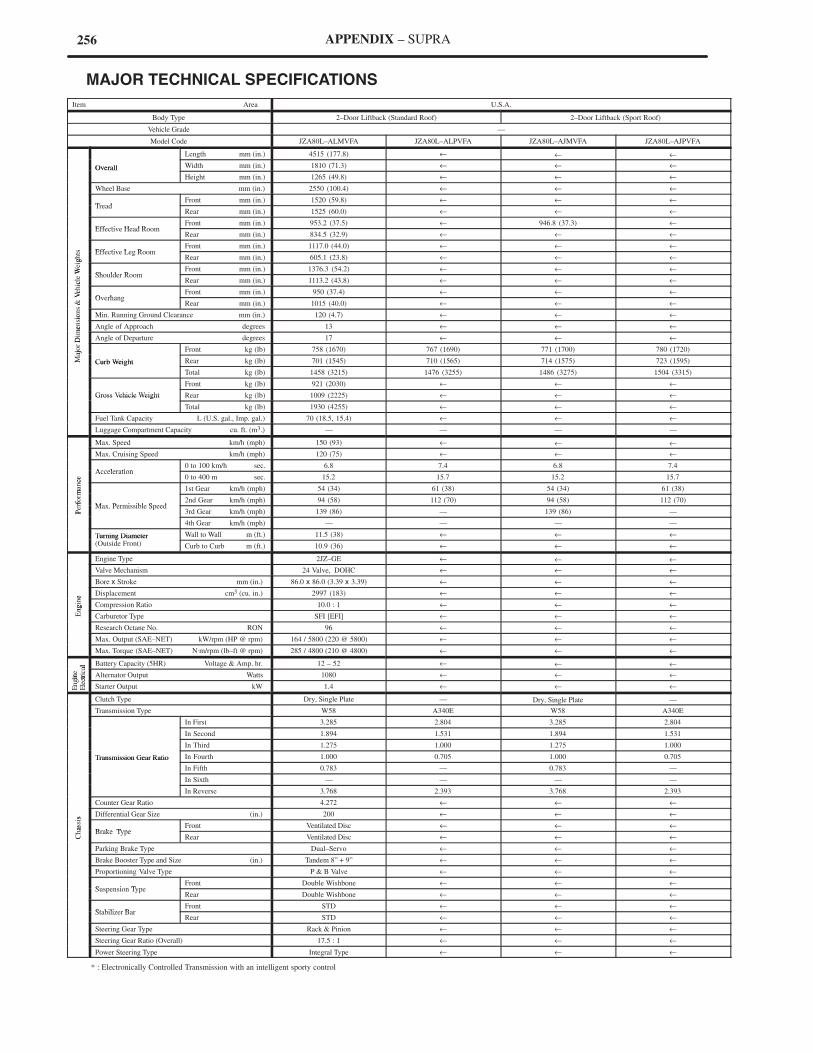
256 APPENDIX – SUPRA
� MAJOR TECHNICAL SPECIFICATIONS
Item Area U.S.A.
Body Type 2–Door Liftback (Standard Roof) 2–Door Liftback (Sport Roof)
Vehicle Grade —
Model Code JZA80L–ALMVFA JZA80L–ALPVFA JZA80L–AJMVFA JZA80L–AJPVFA
Length mm (in.) 4515 (177.8) ← ← ←
Overall Width mm (in.) 1810 (71.3) ← ← ←Overall
Height mm (in.) 1265 (49.8) ← ← ←
Wheel Base mm (in.) 2550 (100.4) ← ← ←
TreadFront mm (in.) 1520 (59.8) ← ← ←
TreadRear mm (in.) 1525 (60.0) ← ← ←
Effective Head RoomFront mm (in.) 953.2 (37.5) ← 946.8 (37.3) ←
Effective Head RoomRear mm (in.) 834.5 (32.9) ← ← ←
s Effective Leg RoomFront mm (in.) 1117.0 (44.0) ← ← ←
ghts Effective Leg Room
Rear mm (in.) 605.1 (23.8) ← ← ←
Wei
gh
Shoulder RoomFront mm (in.) 1376.3 (54.2) ← ← ←
icle
W Shoulder RoomRear mm (in.) 1113.2 (43.8) ← ← ←
Veh
ic
OverhangFront mm (in.) 950 (37.4) ← ← ←
s &
Ve
OverhangRear mm (in.) 1015 (40.0) ← ← ←
sions
&
Min. Running Ground Clearance mm (in.) 120 (4.7) ← ← ←
men
sio
Angle of Approach degrees 13 ← ← ←
Dim
e
Angle of Departure degrees 17 ← ← ←
ajor
D
Front kg (lb) 758 (1670) 767 (1690) 771 (1700) 780 (1720)
Maj
o
Curb Weight Rear kg (lb) 701 (1545) 710 (1565) 714 (1575) 723 (1595)M Curb Weight
Total kg (lb) 1458 (3215) 1476 (3255) 1486 (3275) 1504 (3315)
Front kg (lb) 921 (2030) ← ← ←
Gross Vehicle Weight Rear kg (lb) 1009 (2225) ← ← ←Gross Vehicle Weight
Total kg (lb) 1930 (4255) ← ← ←
Fuel Tank Capacity L (U.S. gal., Imp. gal.) 70 (18.5, 15.4) ← ← ←
Luggage Compartment Capacity cu. ft. (m3.) — — — —
Max. Speed km/h (mph) 150 (93) ← ← ←
Max. Cruising Speed km/h (mph) 120 (75) ← ← ←
Acceleration0 to 100 km/h sec. 6.8 7.4 6.8 7.4
ce
Acceleration0 to 400 m sec. 15.2 15.7 15.2 15.7
man
ce
1st Gear km/h (mph) 54 (34) 61 (38) 54 (34) 61 (38)
rform
a
Max Permissible Speed2nd Gear km/h (mph) 94 (58) 112 (70) 94 (58) 112 (70)
Per
fo
Max. Permissible Speed3rd Gear km/h (mph) 139 (86) — 139 (86) —P
4th Gear km/h (mph) — — — —
Turning Diameter Wall to Wall m (ft.) 11.5 (38) ← ← ←Turning Diameter(Outside Front) Curb to Curb m (ft.) 10.9 (36) ← ← ←
Engine Type 2JZ–GE ← ← ←
Valve Mechanism 24 Valve, DOHC ← ← ←
Bore x Stroke mm (in.) 86.0 x 86.0 (3.39 x 3.39) ← ← ←
e Displacement cm3 (cu. in.) 2997 (183) ← ← ←
ngin
e
Compression Ratio 10.0 : 1 ← ← ←
Eng
Carburetor Type SFI [EFI] ← ← ←
Research Octane No. RON 96 ← ← ←
Max. Output (SAE–NET) kW/rpm (HP @ rpm) 164 / 5800 (220 @ 5800) ← ← ←
Max. Torque (SAE–NET) N.m/rpm (lb–ft @ rpm) 285 / 4800 (210 @ 4800) ← ← ←
al
Battery Capacity (5HR) Voltage & Amp. hr. 12 – 52 ← ← ←
gin
ect
rica
l
Alternator Output Watts 1080 ← ← ←
Engin
Ele
ctr
Starter Output kW 1.4 ← ← ←
Clutch Type Dry, Single Plate — Dry, Single Plate —
Transmission Type W58 A340E W58 A340E
In First 3.285 2.804 3.285 2.804
In Second 1.894 1.531 1.894 1.531
In Third 1.275 1.000 1.275 1.000
Transmission Gear Ratio In Fourth 1.000 0.705 1.000 0.705Transmission Gear Ratio
In Fifth 0.783 — 0.783 —
In Sixth — — — —
In Reverse 3.768 2.393 3.768 2.393
Counter Gear Ratio 4.272 ← ← ←
s Differential Gear Size (in.) 200 ← ← ←
has
sis
Brake TypeFront Ventilated Disc ← ← ←
Chas
Brake TypeRear Ventilated Disc ← ← ←C
Parking Brake Type Dual–Servo ← ← ←
Brake Booster Type and Size (in.) Tandem 8” + 9” ← ← ←
Proportioning Valve Type P & B Valve ← ← ←
Suspension TypeFront Double Wishbone ← ← ←
Suspension TypeRear Double Wishbone ← ← ←
Stabilizer BarFront STD ← ← ←
Stabilizer BarRear STD ← ← ←
Steering Gear Type Rack & Pinion ← ← ←
Steering Gear Ratio (Overall) 17.5 : 1 ← ← ←
Power Steering Type Integral Type ← ← ←
* : Electronically Controlled Transmission with an intelligent sporty control
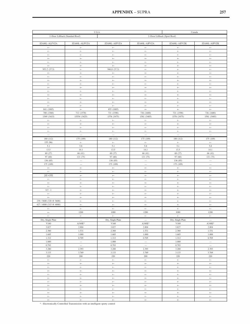
257APPENDIX – SUPRA
U.S.A. Canada
2–Door Liftback (Standard Roof) 2–Door Liftback (Sport Roof)
—
JZA80L–ALFVZA JZA80L–ALPVZA JZA80L–AJFVZA JZA80L–AJPVZA JZA80L–AJFVZK JZA80L–AJPVZK
← ← ← ← ← ←
← ← ← ← ← ←
← ← ← ← ← ←
← ← ← ← ← ←
← ← ← ← ← ←
← ← ← ← ← ←
953.2 (37.5) ← 946.8 (37.3) ← ← ←
← ← ← ← ← ←
← ← ← ← ← ←
← ← ← ← ← ←
← ← ← ← ← ←
← ← ← ← ← ←
← ← ← ← ← ←
← ← ← ← ← ←
← ← ← ← ← ←
← ← ← ← ← ←
← ← ← ← ← ←
841 (1885) ← 855 (1885) ← ← ←
708 (1560) 712 (1570) 721 (1590) 726 (1600) 721 (1590) 726 (1600)
1549 (3415) 15554 (3425) 1576 (3475) 1581 (3485) 1576 (3475) 1581 (3485)
← ← ← ← ← ←
← ← ← ← ← ←
← ← ← ← ← ←
← ← ← ← ← ←
— — — — — —
180 (112) 175 (109) 180 (112) 175 (109) 180 (112) 175 (109)
155 (96) ← ← ← ← ←
5.1 5.8 5.1 5.8 5.1 5.8
13.5 14.1 13.5 14.1 13.5 14.1
60 (37) 66 (41) 60 (37) 66 (41) 60 (37) 66 (41)
97 (60) 121 (75) 97 (60) 121 (75) 97 (60) 121 (75)
136 (85) — 136 (85) — 136 (85) —
175 (109) — 175 (109) — 175 (109) —
← ← ← ← ← ←
← ← ← ← ← ←
2JZ–GTE ← ← ← ← ←
← ← ← ← ← ←
← ← ← ← ← ←
← ← ← ← ← ←
8.5 : 1 ← ← ← ← ←
← ← ← ← ← ←
← ← ← ← ← ←
239 / 5600 (320 @ 5600) ← ← ← ← ←
427 / 4000 (315 @ 4000) ← ← ← ← ←
← ← ← ← ← ←
← 1200 1080 1200 1080 1200
← ← ← ← ← ←
Dry, Single Plate — Dry, Single Plate — Dry, Single Plate —
V160 A340E* V160 A340E* V160 A340E*
3.827 2.804 3.827 2.804 3.827 2.804
2.360 1.531 2.360 1.531 2.360 1.531
1.685 1.000 1.685 1.000 1.685 1.000
1.312 0.705 1.312 0.705 1.312 0.705
1.000 — 1.000 — 1.000 —
0.793 — 0.793 — 0.793 —
3.280 2.393 3.280 2.393 3.280 2.393
3.133 3.769 3.133 3.769 3.133 3.769
220 200 220 200 220 220
← ← ← ← ← ←
← ← ← ← ← ←
← ← ← ← ← ←
← ← ← ← ← ←
← ← ← ← ← ←
← ← ← ← ← ←
← ← ← ← ← ←
← ← ← ← ← ←
← ← ← ← ← ←
← ← ← ← ← ←
← ← ← ← ← ←
← ← ← ← ← ←
* : Electronically Controlled Transmission with an intelligent sporty control