Suppression of Subsynchronous Resonance by a …ipstconf.org/papers/Proc_IPST2005/05IPST022.pdf ·...
6
Suppression of Subsynchronous Resonance by a Parallel Connected Damper Circuit A. M. Miri, C. Sihler, T. Zöller Abstract—Countermeasures to subsynchronous resonance (SSR) are usually based on devices with a high power rating installed in the high voltage network. For damping subsynchronous oscillations and resonance in two island power systems of the Max-Planck-Institute for Plasma Physics (IPP), a novel thyristor controlled damping circuit was developed. The parallel connected damper circuit (PCDC) is directly connected to the generator busbars (in parallel to the generator auxiliary systems) and has a rated power which is thirty times lower than the generator’s nominal power. The PCDC generates active power with a defined frequency corresponding to one of the mechanical natural frequencies of the shaft assembly, thus causing the same effect as an increased natural damping of one of the torsional modes of the shaft system. It is controlled by a direct torque measurement permitting to operate the PCDC independently from other control systems or devices installed in the network. The device is in daily use at IPP where it is applied to two large flywheel generators in the 500 MVA power supply of an experimental tokamak. Based on the experience gained with this application, numerical simulations on applying this proven damping method to turbine generators in utility networks have been performed. They show that a PCDC can be an attractive alternative to conventional SSR countermeasures. Keywords: Subsynchronous oscillation (SSO), subsynchronous resonance (SSR), rotor dynamics, torsional vibration, active damping. I. INTRODUCTION subsynchronous oscillation (SSO) is an electric power system condition where the electric network exchanges significant energy with a turbine generator at one or more of the natural frequencies of the combined system below the synchronous frequencies of the system following a disturbance from equilibrium [1]. Subsynchronous resonance (SSR) is usually discussed in case of power systems with turbine generators and series compensated transmission lines (classical SSR phenomenon). But, according to the definition of SSO, a subsynchronous resonance can also result from the interaction of a turbine generator with a large drive system [2] or fast acting controllers of power system components (device A. M. Miri and T. Zöller are with the University of Karlsruhe, Institut f. Elektroenergiesysteme und Hochspannungstechnik (IEH), Kaiserstr. 12, D- 76128 Karlsruhe, Germany (e-mail: [email protected]). C. Sihler was with the Max-Planck-Institut f. Plasmaphysik (IPP), Boltzmannstr. 2, D-85748 Garching, Germany. Since Oct. 2004 new affiliation and e-mail: GE Global Research ([email protected]). Presented at the International Conference on Power Systems Transients (IPST’05) in Montreal, Canada on June 19-23, 2005 Paper No. IPST05 - 022 dependent SSR phenomenon). Evidence for this statement is supplied by measurement results from the IPP experimental power supply, an isolated power supply based on large flywheel generators. As a countermeasure to the electro- mechanical resonance problems experienced at IPP, a novel thyristor controlled device was developed in order to increase the torsional mode damping in the shaft assembly of the synchronous generators [3]. This active damping method has proven to be very efficient and reliable in more than 3000 dynamic load sequences occurring at a 144 MVA and a 200 MVA flywheel generator during plasma physics experiments conducted in 2003 and 2004. The nominal power of the IPP active damping device can be up to 100 times lower than the nominal power of the synchronous generator, thus enabling a compact and cost-effective design. This paper starts with a short description of conventional SSR damping control methods and their limitations. Section III presents design features and measurement results from IPP’s PCDC. Section IV is dedicated to a further developed design of this active damping device. It is capable to actively damp several torsional modes of a multi-mass system and could be applied to a turbine generator with several natural frequencies below the synchronous (network) frequency. The simulation results presented in Section V show the application of this PCDC as a countermeasure to a typical SSR phenomenon occurring in a utility network. The paper ends with a conclusion on the simulation and test results achieved with this novel method for damping SSR phenomena. II. LIMITATION OF CONVENTIONAL SSR COUNTERMEASURES Considerable effort has been spent over the years address- ing the problem of SSO and SSR [1]. The initial attempt to control subsynchronous resonance oscillations was the use of damper windings in the machine rotors. This was followed by the use of a supplementary control in the excitation system, which became known as the power system stabilizer (PSS). The use of equipment such as SVC and other FACTS devices that exploit the advancement in power electronics showed impressive performance improvements in a single machine - infinte bus system and occasionally in somewhat more complex three or four machine systems. But there is hardly any performance improvement in studies of large practical- sized power systems compared to that obtainable from a properly tuned conventional PSS [4]. In many situations there is even performance degradation through adverse interactions between controls. In a large power system, following a disturbance, the machines do not oscillate in phase or with the A
Transcript of Suppression of Subsynchronous Resonance by a …ipstconf.org/papers/Proc_IPST2005/05IPST022.pdf ·...
Suppression of Subsynchronous Resonance by a Parallel Connected Damper Circuit
A. M. Miri, C. Sihler, T. Zöller
Abstract—Countermeasures to subsynchronous resonance (SSR) are usually based on devices with a high power rating installed in the high voltage network. For damping subsynchronous oscillations and resonance in two island power systems of the Max-Planck-Institute for Plasma Physics (IPP), a novel thyristor controlled damping circuit was developed. The parallel connected damper circuit (PCDC) is directly connected to the generator busbars (in parallel to the generator auxiliary systems) and has a rated power which is thirty times lower than the generator’s nominal power. The PCDC generates active power with a defined frequency corresponding to one of the mechanical natural frequencies of the shaft assembly, thus causing the same effect as an increased natural damping of one of the torsional modes of the shaft system. It is controlled by a direct torque measurement permitting to operate the PCDC independently from other control systems or devices installed in the network. The device is in daily use at IPP where it is applied to two large flywheel generators in the 500 MVA power supply of an experimental tokamak. Based on the experience gained with this application, numerical simulations on applying this proven damping method to turbine generators in utility networks have been performed. They show that a PCDC can be an attractive alternative to conventional SSR countermeasures.
Keywords: Subsynchronous oscillation (SSO),
subsynchronous resonance (SSR), rotor dynamics, torsional vibration, active damping.
I. INTRODUCTION subsynchronous oscillation (SSO) is an electric power system condition where the electric network exchanges
significant energy with a turbine generator at one or more of the natural frequencies of the combined system below the synchronous frequencies of the system following a disturbance from equilibrium [1]. Subsynchronous resonance (SSR) is usually discussed in case of power systems with turbine generators and series compensated transmission lines (classical SSR phenomenon). But, according to the definition of SSO, a subsynchronous resonance can also result from the interaction of a turbine generator with a large drive system [2] or fast acting controllers of power system components (device A. M. Miri and T. Zöller are with the University of Karlsruhe, Institut f. Elektroenergiesysteme und Hochspannungstechnik (IEH), Kaiserstr. 12, D-76128 Karlsruhe, Germany (e-mail: [email protected]). C. Sihler was with the Max-Planck-Institut f. Plasmaphysik (IPP), Boltzmannstr. 2, D-85748 Garching, Germany. Since Oct. 2004 new affiliation and e-mail: GE Global Research ([email protected]). Presented at the International Conference on Power Systems Transients (IPST’05) in Montreal, Canada on June 19-23, 2005 Paper No. IPST05 - 022
dependent SSR phenomenon). Evidence for this statement is supplied by measurement results from the IPP experimental power supply, an isolated power supply based on large flywheel generators. As a countermeasure to the electro-mechanical resonance problems experienced at IPP, a novel thyristor controlled device was developed in order to increase the torsional mode damping in the shaft assembly of the synchronous generators [3]. This active damping method has proven to be very efficient and reliable in more than 3000 dynamic load sequences occurring at a 144 MVA and a 200 MVA flywheel generator during plasma physics experiments conducted in 2003 and 2004. The nominal power of the IPP active damping device can be up to 100 times lower than the nominal power of the synchronous generator, thus enabling a compact and cost-effective design. This paper starts with a short description of conventional SSR damping control methods and their limitations. Section III presents design features and measurement results from IPP’s PCDC. Section IV is dedicated to a further developed design of this active damping device. It is capable to actively damp several torsional modes of a multi-mass system and could be applied to a turbine generator with several natural frequencies below the synchronous (network) frequency. The simulation results presented in Section V show the application of this PCDC as a countermeasure to a typical SSR phenomenon occurring in a utility network. The paper ends with a conclusion on the simulation and test results achieved with this novel method for damping SSR phenomena.
II. LIMITATION OF CONVENTIONAL SSR COUNTERMEASURES Considerable effort has been spent over the years address-
ing the problem of SSO and SSR [1]. The initial attempt to control subsynchronous resonance oscillations was the use of damper windings in the machine rotors. This was followed by the use of a supplementary control in the excitation system, which became known as the power system stabilizer (PSS). The use of equipment such as SVC and other FACTS devices that exploit the advancement in power electronics showed impressive performance improvements in a single machine - infinte bus system and occasionally in somewhat more complex three or four machine systems. But there is hardly any performance improvement in studies of large practical-sized power systems compared to that obtainable from a properly tuned conventional PSS [4]. In many situations there is even performance degradation through adverse interactions between controls. In a large power system, following a disturbance, the machines do not oscillate in phase or with the
A

same period. Therefore, a damping control based on only one device installed in the high voltage network cannot be beneficial to all synchronous machines. A non-interacting damping controller would have to be based on devices installed close to the generating plants and acting directly on the mechanical shaft systems. In principle, a damper based on the excitation system could fulfill the requirement of non-interacting damping. But an exciter system cannot provide significant damping for large SSO (limited power rating of exciter, speed of response … [5]).
Prerequisite for a torsional mode damper based on a separate device providing the required damping power is a measurement device being capable of measuring torsional vibrations in large diameter drive trains with sufficient accuracy. Because of the high stiffness of rigid shaft systems, the torsion angles along the shaft are very small (hundredths to tenths of a degree) but the resulting torsional stress can reach a high level (MNm). The small torsion angle and the high rotational speed of a turbine generator shaft make it difficult to measure torsional oscillations if conventional measurement methods are applied (e. g. based on speed sensors at both ends of the shaft). Therefore, it does not come as a surprise that none of the SSO or SSR countermeasures being applied in utility networks are based on a direct active damping of a torsional mode by means of real power (damping of a mechanical oscillation requires real power). However, an accurate and reliable, contact-less sensor enabling to directly (inductively) measure the torque at different locations of the shaft assembly has recently become commercially available [6]. If the sensor is installed close to the location where a relevant torsional mode is expected, even relatively small torsional oscillations can be measured without extensive filtering. This permits to design a control loop with a real-time characteristic [3]. In using the signal from the direct torque measurement in a thyristor controlled feedback circuit, a PCDC can be designed which has the same effect as an increased natural damping of a torsional mode.
A PCDC installed directly at the generator busbars and generating active power with only one defined frequency (corresponding to a resonant frequency of the generator shaft assembly) could provide non-interacting damping if the neighbored machines have different resonance points. Since large synchronous generators can be characterized by sharp resonance points (e. g. f0 ± 0.2 Hz) this requirement could be fulfilled in many power systems. In cases where generators of the same mechanical design are located in one power plant, the torsional mode damping of the single generators could be increased by only one PCDC being controlled by several torque sensors installed at the single generators, in a similar way as described in Section IV where one PCDC is used to damp several torsional modes.
III. DESIGN AND PERFORMANCE OF THE PCDC SYSTEMS IN THE IPP ISLAND NETWORKS
At IPP, the thyristor controlled damping method for
torsional oscillations was devised to solve problems which were experienced in the power supply of the ASDEX Upgrade (AUG) tokamak. The power and energy for the plasma experiments conducted with this experimental tokamak are supplied by large flywheel generators (synchronous machines), the biggest of which can deliver a power of 150 megawatts for ten seconds with a flywheel weighing 230 tons. The flywheel generators supply high-power thyristor converters. They enable a fast control of the DC currents in the magnet coils used for magnetic confinement of the plasma in the static and dynamic case. Because of problems with electromechanical resonances leading to a damaged coupling in the shaft assembly of the EZ4 generator, torque measurement and protection systems were installed (see Fig. 2). The torque measuring concept is based on the anisotropic magnetostrictive effect in ferromagnetic materials which is measured by a novel contact-less inductive sensor [6]. A measurement result showing a resonant excitation of the EZ4 shaft is shown in Fig. 2. Many plasma experiments had to be prematurely terminated by the generator protection system in order to prevent negative effects on the durability of the shaft assemblies. A torque reduction by a factor of two could be achieved by a solution based on changing parameters of the
Fig. 1. One of the flywheel generators at IPP with the big flywheel in the middle and the generator on the right. The arrow shows where the torque sensor was installed.
Fig. 2. Measured output power and torque at the rotor-flywheel coupling of generator EZ4
Time/s
106001582
Text Box

plasma control system. But this solution adversely affected the dynamic performance of the plasma control system, so that a non-interacting damping method had to be developed. The method is based on applying an additional electrical torque through the stator winding, thus causing the same effect as one (or more) increased coefficient(s) in the mechanical damping matrix of the shaft system [3]. Since the thyristor controlled PCDC generates real power respectively an electro-magnetic torque acting on the rotor with a frequency corresponding to a resonant frequency, this damping method is very efficient. The application of a PCDC requires suitable protection systems and commissioning procedures, especially if the damping circuit is designed for generating a damping power in the range of megawatts. With not properly set control parameters, the PCDC could excite a torsional oscillation instead of diminishing it. This is demonstrated in Fig. 3 which shows measurement results from the commissioning of a PCDC in the network of a 144 MVA generator (flywheel generator EZ3). To be able to set all damping control parameters without having to wait until the plasma control system of ASDEX Upgrade causes torsional oscillations in the shaft system of the synchronous machine, the thyristor controlled device is at first used for generation and then for damping of a torsional oscillation. The oscillation is generated in operating the control circuit of the PCDC open-loop (t < 2 s in Fig. 3). In this mode of operation, the reference for the current-controlled thyristor converter is provided by means of a signal generator and a programmable logical control. Then, at t = 2 s in Fig. 3, during the current zero-crossing of the converter current, the feedback loop is closed. Now, a decrease of the EZ3 torque amplitude can be observed because the active power generated by the PCDC is
approximately in counter-phase to the torsional velocity of the shaft assembly (at the location where the torque sensor is installed). In Fig. 3 the damping effect is not very high because the damping circuit has not been tuned yet to the optimum phase relation, i. e. the damping torque is not exactly in counter-phase to the torsional velocity of the oscillation. Once all control parameters are properly set, a PCDC can be continuously used to damp one torsional mode of oscillation efficiently. Since the feedback control is based on a torque measurement, the damping effect does not depend on the cause of excitation which can be of an electrical or mechanical nature, e. g. a mechanical or electrical disturbance or harmonics. Therefore, no adjustments to control parameters are necessary if load conditions are changed.
Stability analyses, parametrical studies and tests have shown that this damping method can also be applied if a high damping power or a high operational gain in the control loop is desired. At high operational gain, the PCDC enables to suppress torsional oscillations which is shown in Fig. 4. This figure also shows that a PCDC has the same effect as an increased natural damping for one torsional mode, the degree of damping being electronically adjustable.
IV. DESIGN AND PERFORMANCE OF A PCDC FOR DAMPING SSR
A. PCDC for a multi-mass system Applying this damping method to a large turbine generator requires a further developed design of the control module of the active damping device. A six pulse thyristor bridge is sufficient for this type of application because the most relevant torsional modes of turbine generator shaft assemblies correspond to resonant frequencies below the synchronous frequency (50 or 60 Hz). Fig. 5 shows an example design of a PCDC for the shaft assembly of the IEEE First Benchmark Model for Computer Simulation of SSR
EZ3 statorcurrent
EZ3 activepower
EZ3 torque
Load circuit:
Converter
voltage
Converter
current
Reference
Measured
1.5 MW
500 kNm
520 V
3 kA
t = 2.0 s: Feedback loop closed (active damping enabled)Excitation (feedforward) Damping (feedback)
Fig. 3. Measurement results from commissioning a PCDC on a 144 MVAgenerator. The same device is used for excitation (t < 2 s) and damping ofthe torsional oscillation (1st natural frequency of shaft system: 24 Hz)
Fig. 4. Excitation of the shaft assembly of a 220 MVA generator into a torsional resonance and application of a PCDC with low and high operational gain in the feedback controlled damping circuit (1st natural frequency: 26 Hz)

[7]. The turbine generator has a nominal power of 890 MVA. The main components of the shaft system are the exciter, the generator, two low pressure turbines (LBA and LPB), an intermediate pressure turbine (IP), and a high presure turbine (HP). The torsional mode natural frequencies fo are:
fo = 15.7; 20.2; 25.6; 32.3 and 47.5 [Hz].
As shown in Fig. 5, a PCDC with extended control module would be capable of simultaneously damping several torsional modes occurring in the shaft system. A case where two torsional modes are simultaneously excited is unlikely to occur in a real power system In the simulation, the two torsional modes, corresponding to fo = 15.7 and 32.3 Hz, were simultaneously excited by means of an external device, in a similar way as shown in Fig. 3. The resulting torques at different locations of the shaft system are dominated by oscillations with a low natural damping. They consist of two frequencies. One second after the excitation the PCDC is activated. It provides a damping power consisting of two frequencies, so that the two-mode oscillation can be terminated within two seconds.
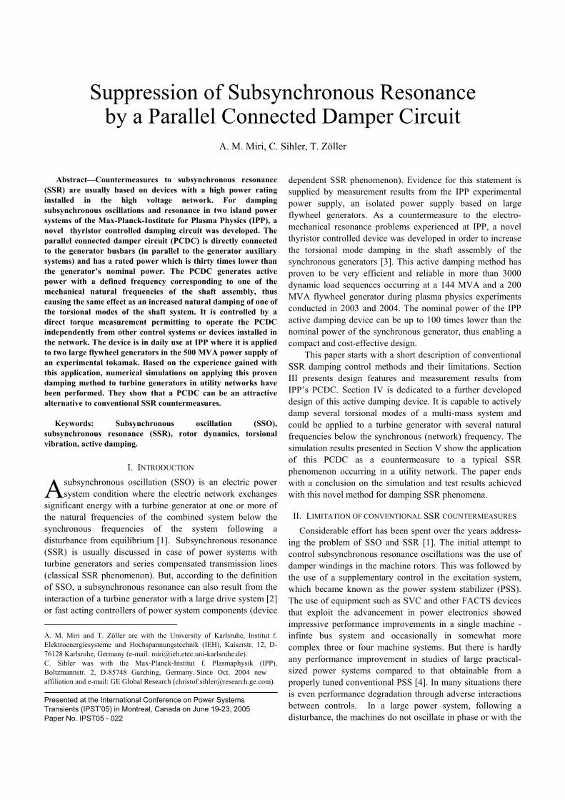
B. Active damping of a classical SSR phenomenon For demonstrating the performance of a PCDC in damping a classical SSR phenomenon, not the First but the Second IEEE Benchmark Model for Computer Simulation
of SSR was selected. The simple type of power system employed in the First Benchmark Model, with its single series resonance would rarely be encountered in actual operation of a power system [8]. The circuit diagram of the model configuration is shown in Fig. 6. The turbine generator has a nominal power of 600 MVA and a nominal voltage of 22 kV. The main components of the shaft system are the exciter, the generator, a low pressure turbine (LP), and a high pressure turbine (HP). The torsional mode natural frequencies of this shaft system are:
fo = 24,65; 32.39; and 51.1 [Hz].
The selected Second Benchmark Model configuration consists of a single generator connected to two lines, one of which is series compensated. A compensation value of 55 % has been chosen in the compensated line since this provides the best tuning for the first torsional mode. In order to avoid that the simulation results are affected by too optimistic assumptions for the natural mode damping, damping coefficients were applied which were derived from measurements performed at IPP (which represent the torsional mode damping of shaft assemblies in the no-load case). In literature, the simulations are usually performed with higher natural damping values in order to achieve that the simulation model is steady-state stable when the fault occurs in torque amplification studies [8]. As can be seen in Fig. 7, a
Power module ofdamping device
Control module of thyristor converter
Sensor 1 Sensor 2
Σ
Phase shifterand inverter
Phase shifterand inverter
Phase shifterand inverter
BP
15.7Hz
25.6Hz
32.3Hz
BP
BP
Extended controlmodule of damping
device
Fig. 7. Active damping of several torsional modes in the shaft assembly of a turbo-generator: The schematic shows one possible arrangement(thyristor controlled device with two torque sensors), the curves show the termination of a two-mode oscillation (16 and 32 Hz component) within 2 s.
00
00
0
50
00
50
00
50
00
50
00
50
50
00
50
00
5015
10
5
0
-5
-10
-15
-20
-25
LPA-LPB [MNm]
LPB-GEN[MN ]
Start of active damping
Power[MW] x 2
Torque
T LPB-GEN
Pdamp
1 s
Power module ofdamping device
Fig. 5. Active damping of the first and third torsional mode in the shaft assembly of an 890 MVA turbine generator. The generator was excited totorsional resonance oscillations in a similar way as shown in Fig. 3. Then, after 1 s, the PCDC is activated which terminates the oscillations within 2 s.
PCDC
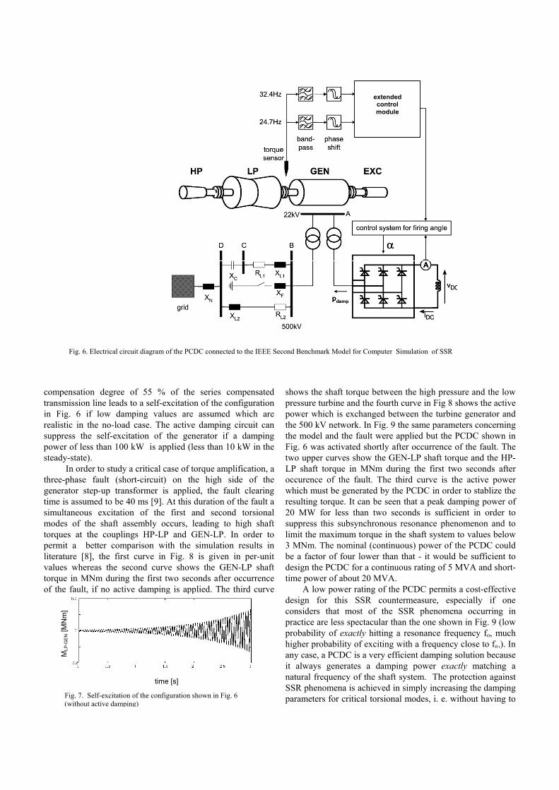
compensation degree of 55 % of the series compensated transmission line leads to a self-excitation of the configuration in Fig. 6 if low damping values are assumed which are realistic in the no-load case. The active damping circuit can suppress the self-excitation of the generator if a damping power of less than 100 kW is applied (less than 10 kW in the steady-state).
In order to study a critical case of torque amplification, a three-phase fault (short-circuit) on the high side of the generator step-up transformer is applied, the fault clearing time is assumed to be 40 ms [9]. At this duration of the fault a simultaneous excitation of the first and second torsional modes of the shaft assembly occurs, leading to high shaft torques at the couplings HP-LP and GEN-LP. In order to permit a better comparison with the simulation results in literature [8], the first curve in Fig. 8 is given in per-unit values whereas the second curve shows the GEN-LP shaft torque in MNm during the first two seconds after occurrence of the fault, if no active damping is applied. The third curve
shows the shaft torque between the high pressure and the low pressure turbine and the fourth curve in Fig 8 shows the active power which is exchanged between the turbine generator and the 500 kV network. In Fig. 9 the same parameters concerning the model and the fault were applied but the PCDC shown in Fig. 6 was activated shortly after occurrence of the fault. The two upper curves show the GEN-LP shaft torque and the HP-LP shaft torque in MNm during the first two seconds after occurence of the fault. The third curve is the active power which must be generated by the PCDC in order to stablize the resulting torque. It can be seen that a peak damping power of 20 MW for less than two seconds is sufficient in order to suppress this subsynchronous resonance phenomenon and to limit the maximum torque in the shaft system to values below 3 MNm. The nominal (continuous) power of the PCDC could be a factor of four lower than that - it would be sufficient to design the PCDC for a continuous rating of 5 MVA and short-time power of about 20 MVA.
A low power rating of the PCDC permits a cost-effective design for this SSR countermeasure, especially if one considers that most of the SSR phenomena occurring in practice are less spectacular than the one shown in Fig. 9 (low probability of exactly hitting a resonance frequency fo, much higher probability of exciting with a frequency close to fo,). In any case, a PCDC is a very efficient damping solution because it always generates a damping power exactly matching a natural frequency of the shaft system. The protection against SSR phenomena is achieved in simply increasing the damping parameters for critical torsional modes, i. e. without having to
Fig. 7. Self-excitation of the configuration shown in Fig. 6 (without active damping)
MLP
-GEN
[MN
m]
time [s]
Figure 6: Electrical network representation of IEEE Second Benchmark Model for SSR simulations and activedamping circuit for a turbine generator (with an extended control module for the multi-mass system)
extended control module
Fig. 6. Electrical circuit diagram of the PCDC connected to the IEEE Second Benchmark Model for Computer Simulation of SSR
106001582
Text Box

consider “the rest” of the power system. Therefore, a PCDC would well qualify as a supplement to other SSR countermeasures (triggering of other SSR countermeasures, such as a protection relay or system switching, only if the PCDC damping power exceeds a predefined value).
V. CONCLUSIONS The design and performance of a parallel connected damper circuit (PCDC) has been investigated by simulation and measurement, in order to analyze its feasibility as an SSR countermeasure. In controlling the PCDC by means of a direct torque measurement, torsional modes occurring in the generator’s shaft assembly can be damped in a very efficient way. This permits a design of the PCDC with a rated power of typically two orders of magnitude lower than the rating of the turbine generator. The low power rating enables to install the PCDC at the medium voltage level, preferably in parallel to the generator’s auxiliary systems. A well designed PCDC installed close to the generator busbars and generating active power with only a few defined frequencies can provide non-
interacting damping control for SSR phenomena in large and complex networks. In eliminating interaction problems by means of the PCDC design instead of using a complex damping control system, this type of device can easily and subsequently be installed in a power system, for instance as a supplement to already existing SSR countermeasures.
VI. REFERENCES [1] P. M. Anderson, B. L. Agrawal, J. E. Van Ness, Subsynchronous
Resonance in Power Systems, New York: IEEE Press, 1990, pp. 1-269. [2] F. Joswig, S. Kulig, "Perceptions about new kinds of subsynchronous
resonances", Proc. 4th IPST, Rio de Janeiro, Brazil, pp. 228-233, 2001. [Online]. Available: http://www.ipst.org/TechPapers/2001/IPST01
[3] C. Sihler, A. M. Miri, A. Harada and ASDEX Upgrade Team, “Damping of Torsional Resonances in Generator Shafts Using a Feedback Controlled Buffer Storage of Magnetic Energy”. Proc. 5th IPST, New Orleans, LA 2003, Paper 6b-3. [Online]. Available: http://www.ipst.org/TechPapers/2003/IPST03/Paper6b-3.pdf
[4] CIGRE Task Force 38.02.17, Advanced Angle Stability Controls, Final Report (App. J): “A New Look at Damping Control”, Dec. 1999. [Online]. Available: http://www.transmission.bpa.gov/orgs/opi/cigre
[5] IEEE SSR Working Group, “Countermeasures to SSR Problems”, IEEE Transactions on Power Apparatus and Systems, Vol. PAS-99, No. 5, 1980, pp. 1810-1816
[6] P. Lang, S. Kulig, product: “Torsional stress analyzer”, 2001 [Online]. Available: http://www.itwm.fhg.de
[7] IEEE SSR Task Force, “First Benchmark Model for Computer Simulation of SSR”, Power Systems Engineering Committee, IEEE Trans on PAS, Sept./Oct. 1977.
[8] IEEE SSR Working Group, “Second Benchmark Model for Computer Simulation of SSR”, IEEE Trans. On Power Apparatus and Systems, Vol. PAS-104, No. 5, May 1985
[9] A. M. Miri, Ausgleichsvorgänge in Elektroenergiesystemen, Berlin, New York: Springer-Verlag, 2000
Fig. 8. SSR excitation in the Second Benchmark Model (three-phase fault , clearing time 40 ms): Shaft torques (upper three curves) and turbine-generator active power
MLP
-GEN
[pu]
100 ms
Fig. 9. Active damping of the SSR shown in Fig. 8 (damping circuit configuration as shown in Fig. 6): GEN-LP, HP-LP shaft torque (upper two curves) and active power generated by the damping device