Suppression of small electrical cable fires with Fine water … mist fire suppression experiments...
36
Naval Research Laboratory Washington, DC 20375-5320 NRL/MR/6180--06-8941 Mechanism of Suppression and Extinguishment of Communication Cable Fire by Ultra Fine Water Mist in Cross-Flow April 14, 2006 Approved for public release; distribution is unlimited. RAMAGOPAL ANANTH DAMIAN ROUSON FREDERICK W. WILLIAMS Navy Technology Center for Safety and Survivability Chemistry Division CHUKA C. NDUBIZU Geo-Centers, Inc. Arlington, VA
Transcript of Suppression of small electrical cable fires with Fine water … mist fire suppression experiments...

Naval Research LaboratoryWashington, DC 20375-5320
NRL/MR/6180--06-8941
Mechanism of Suppression andExtinguishment of CommunicationCable Fire by Ultra Fine WaterMist in Cross-Flow
April 14, 2006
Approved for public release; distribution is unlimited.
RAMAGOPAL ANANTH
DAMIAN ROUSON
FREDERICK W. WILLIAMS
Navy Technology Center for Safety and SurvivabilityChemistry Division
CHUKA C. NDUBIZU
Geo-Centers, Inc.Arlington, VA

i
REPORT DOCUMENTATION PAGE Form ApprovedOMB No. 0704-0188
3. DATES COVERED (From - To)
Standard Form 298 (Rev. 8-98)Prescribed by ANSI Std. Z39.18
Public reporting burden for this collection of information is estimated to average 1 hour per response, including the time for reviewing instructions, searching existing data sources, gathering and maintaining the data needed, and completing and reviewing this collection of information. Send comments regarding this burden estimate or any other aspect of this collection of information, including suggestions for reducing this burden to Department of Defense, Washington Headquarters Services, Directorate for Information Operations and Reports (0704-0188), 1215 Jefferson Davis Highway, Suite 1204, Arlington, VA 22202-4302. Respondents should be aware that notwithstanding any other provision of law, no person shall be subject to any penalty for failing to comply with a collection of information if it does not display a currently valid OMB control number. PLEASE DO NOT RETURN YOUR FORM TO THE ABOVE ADDRESS.
5a. CONTRACT NUMBER
5b. GRANT NUMBER
5c. PROGRAM ELEMENT NUMBER
5d. PROJECT NUMBER
5e. TASK NUMBER
5f. WORK UNIT NUMBER
2. REPORT TYPE1. REPORT DATE (DD-MM-YYYY)
4. TITLE AND SUBTITLE
6. AUTHOR(S)
8. PERFORMING ORGANIZATION REPORT NUMBER
7. PERFORMING ORGANIZATION NAME(S) AND ADDRESS(ES)
10. SPONSOR / MONITOR’S ACRONYM(S)9. SPONSORING / MONITORING AGENCY NAME(S) AND ADDRESS(ES)
11. SPONSOR / MONITOR’S REPORT NUMBER(S)
12. DISTRIBUTION / AVAILABILITY STATEMENT
13. SUPPLEMENTARY NOTES
14. ABSTRACT
15. SUBJECT TERMS
16. SECURITY CLASSIFICATION OF:
a. REPORT
19a. NAME OF RESPONSIBLE PERSON
19b. TELEPHONE NUMBER (include areacode)
b. ABSTRACT c. THIS PAGE
18. NUMBEROF PAGES
17. LIMITATIONOF ABSTRACT
Mechanism of Suppression and Extinguishment of Communication Cable Fireby Ultra Fine Water Mist in Cross-Flow
Chuka C. Ndubizu,* Ramagopal Ananth, Damian Rouson, and Frederick W. Williams
NRL/MR/6180--06-8941
Approved for public release; distribution is unlimited.
Unclassified Unclassified UnclassifiedUL 36
Ramagopal Ananth
(202) 767-3197
Fire suppressionWater mist
14-04-2006 Memorandum Report
Navy cable
Naval Research Laboratory, Code 61804555 Overlook Avenue, SWWashington, DC 20375-5320
Water mist fire suppression experiments were performed in cross-flow on bare (without outer jacket) communication cables to simulate a worst-case scenario. As fine water droplets are injected at low inlet velocities, an initial envelope flame that engulfed the circumference of the cable recedes and forms a wake flame stabilized behind the cable. At high mist concentration and/or high air velocity, the flame is extinguished by flame shrinking rather than by flame blow-off, as is the case in flat plate boundary layer flames. Ultra fine mist (UFM), with droplet diameter (d ~3 μm), is more effective in reducing the extinguishment time than the high-pressure spray nozzle mist (d ~ 20 μm), which introduces spray-induced turbulence. Extinguishment proceeds rapidly after a threshold concentration is exceeded, and the threshold concentration decreases with air velocity. Finally, the copper cylindrical mesh, which is part of the cable, significantly enhances the effectiveness of UFM in flame extinguishment.
Office of Naval ResearchOne Liberty Center875 North Randolph StreetArlington, VA 22203-1995
*Geo-Centers, Inc., Arlington, VA
ONR

CONTENTS
1.0 INTRODUCTION …………………………………………………….. 1 2.0 EXPERIMENTAL ………………………………………………………. 3
2.1 Mist Generation and Characterization ……………………………5 2.2 Test Procedure…………………………………………………… 7
3.0 RESULTS AND DISCUSSION ………………………………………… 11 4.0 SUMMARY …………………………………………………………….. 29 5.0 ACKNOWLEDGEMENTS …………………………………………….. 30 6.0 REFERENCES ………………………………………………………… 30 APPENDIX ……………………………………………………………... A-1
iii

1. Mechanism of suppression and extinguishment of communication cable fire by ultra fine water mist in cross-flow
1.0 INTRODUCTION
The growing reliance on electronic data and network technology has resulted in a
greater need to protect electrical cables in the event of fire. Electrical cable fires are often initiated by electrical power overload and accidents (for example during welding). Loses due to electrical cable fires are compounded by the resultant interruption in production because of the high reliance on automation. A review [1] of industrial cable fire incidents in the 1990’s by Factory Mutual Research Corporation reveals that about 78% of the losses in the fires was due to interruption in production. That level of interruption would be disastrous in the military. Furthermore, the current policy of reduced manning in the Navy and heavy dependence on automation, makes for a more pressing need to provide adequate fire protection for the ship’s false deck / sub floor area, where many of the critical cables pass.
Traditionally, a passive approach has been adopted to provide fire protection for electrical cables in both civilian and military applications. This involves improving the fire resistance of the cable insulators and outer jackets. McClung and Ramachandran [2] discussed a method of making polyethylene cable insulator fire retardant by introducing some hydrated mineral fillers like aluminum trihydrate. The filler makes it fire retardant by (a) reducing the fuel (polymer) content; (b) absorbing heat from fire (endothermic) and (c) decomposing to generate water vapor, which helps to cool the fire and dilute the oxygen concentration. Several tests had been carried out to study the effectiveness of these passive measures and these studies generally include measurements of heat release rates, flame spread, toxic gas and smoke production rates, and potential for electrical short-circuiting [3-6]. For example, Coaker et al [3] conducted fire performance tests with vinyl wire cables where the primary insulation is a fire retardant vinyl. They conducted both large scale and small cone calorimeter tests with the cable and insulating material. They showed that the vinyl wires performed well under fire and that the small-scale tests correlated well with the large-scale tests.
Alexander et al [5,6] conducted full-scale compartment fire tests, where they
studied the effectiveness of the passive measures on Navy cables in the ship and submarine environment. The tests compared the burning characteristics of power, communication and control cables, which had passive fire protection. These characteristics include ease of ignition, fire spread rate, heat release rate, smoke production rate and toxic and corrosive gas production rates. Their results show that power cables, which had silicone/glass insulation are quite resistant to fire and produce less smoke and toxic and corrosive gases. However, Navy communication cables, which have polyethylene insulation, burn profusely when the outer jacket peels off. In the current work, we study the burning characteristics of the Navy communication cable without the outer jacket.
1
_______________Manuscript approved January 30, 2006.
2
While passive protection approach has been effective in many cases, an active fire fighting system such as water mist must also be developed for a comprehensive approach towards damage control on ships. Water mist systems have the advantage of being relatively cheap, non-toxic and can suppress class A fires effectively. Large-scale electrical cable and electronic cabinet fire protection tests have been conducted using water hose, regular [7] and Hi-fog [8] sprinkler systems. The regular sprinkler and water hose droplets have mean droplet diameters ≥ 1000 µm [9], while Hi-fog systems, which are run at very high pressures produced droplets in the 60 µm mean droplet range. These systems produce large water flow rates and hence cause considerable collateral damage. Recent research results suggest that smaller diameter mist droplets would be more effective in suppressing and extinguishing fires, especially pool fires in enclosures. Traditionally, high-pressure nozzles are used to generate fine water mist. However to produce mean droplets <10 µm the high pressure requirement would be expensive to install and maintain. Recent developments pioneered by NanoMist SystemsP
®P (Adiga and
Adiga, 2003) [10] in the extraction of ultra fine mist (UFM) generated by ultrasonic vibration of piezoelectric discs have made the use of UFM relatively more attractive than before. Very large flow rates of ultra fine mist can now be produced with ultrasonic mist generators. Mist from this system has Sauter mean diameters (SMD) in the range of 5 µm compared to about 20 to 100 µm for fine spray droplets at moderate pressures [9]. The advantage of this system over nozzles and sprinklers is that the mist flow rate can be varied independent of the droplet size. This is accomplished by varying the number piezoelectric discs that is energized. In the nozzle or sprinkler systems, flow rate and droplet size are varied together by changing the orifice size and/or water pressure.
Ultra fine water droplets will evaporate very fast because of the dP
2P law. They are
likely to be very effective for application in enclosed spaces especially enclosed electronic spaces, where water damage is very undesirable. Recently, large-scale tests were conducted to study the feasibility of using ultra fine mist (UFM) to protect ship sub-floors [11], which normally house cables and electronic equipments. Experiments were performed in a 200 cm x 190 cm x 30 cm simulated ship sub-floor. Two fire scenarios were tested, namely; an Underwriters Laboratory standard n-heptane “telltale” fire which is hard to extinguish with regular spray nozzle mist [12] and Underwriters Laboratory standard plastic sheet array fire. UFM flow rate into the enclosure varied between 140 and 220 cmP
3P/min. Two electronic targets were exposed, a modem and an uncoated circuit
board to the UFM to test the extent of water damage to electronic components. The results show that a 0.053 lpm/mP
2P UFM flux with a concentration of about 300 g/mP
3P
extinguished the telltale fire in about 3 minutes, while the plastic array fire was readily extinguished with less concentration of UFM. Operating electronics shut down after extended exposure to UFM but regained functionality after drying. Finally the results show that UFM can provide adequate fire protection with minimal water damage to the ship sub-floor in case of below deck fire exposure. UFM was very effective compared to large droplet sprays because UFM evaporates faster and a larger proportion of the droplets are converted to vapor reducing the oxygen concentration at the seat of this fire.
3
Laboratory-scale studies on the effectiveness of UFM are lacking. With the new
technology for extracting large flow of UFM from ultrasonic mist generators we can now conduct laboratory-scale experiments, where we study independently the effects of one mist parameter on suppression and extinction, which we could not do with nozzles. Recently, Ndubizu et al [13] conducted suppression experiments on boundary layer flames over a 7.5 cm by 9.5 cm PMMA plate. They studied the effects of flow velocity on the extinction concentration of UFM and showed that the extinction concentration decreases linearly with flow velocity. They also compared the performance of UFM and spray nozzle mist whose mean diameters are in the range of 11 to 50 µm. They measured the mist concentration at the flame location and showed that at the forced flow velocity of 84 cm/s the UFM is less effective than the spray nozzle mist. They deduced that the UFM evaporated too early because of their small size such that the effects of latent heat was not optimally utilized. Their results with spray nozzle mist also reveal that at air velocity of 84 cm/s, an optimum extinction mean droplet diameter is in the range 30 µm. This result ignores the effects of nozzle spray-induced turbulence. In this work, we present results of similar laboratory studies. We study the extinguishment characteristics of UFM as the mist flow rate varies while the droplet size remained constant. We also compare the effectiveness of UFM (d~ 3 µm) and spray nozzle mist (d ~ 20 µm) in cross-flow on single communication cable fires, where the effects of geometry (cylinder instead of flat plate) would play a role.
There are also related experimental and theoretical studies on burning
characteristics of cylindrical rods without water mist, which reveal the effects of geometry and other physical parameters [14]. Goldmeer et al. [14] studied the burning and extinction of PMMA rods in normal and micro-gravity and the effects of pressure and velocity on the mode of extinguishment. Unlike in the current study they ran experiments and numerical simulations with 19 mm rods in cross-flow without mist. Their results reveal that the flame can be extinguished by quenching (continuous shrinking and eventual extinction) and by blow-off depending on the cross-flow velocity, U, chamber pressure, and rod centerline temperature. They reported the formation of wake flame at high velocity. In microgravity quenching occurs for U < 5 cm/s and blow-off is obtained for U > 15 cm/s. They concluded that blow-off is due to low Damkohler number Da while quenching occurs as the flame shrinks and the net fuel surface heat radiation becomes positive. The current work focuses on the effects of ultra fine water mist suppressant on the burning characteristics of Navy communication cables in cross-flow, normal gravity and atmospheric pressure. We show the formation of wake flame with the introduction of UFM and also that the flame extinguishes rapidly after a threshold mist concentration.
2.0 EXPERIMENTAL
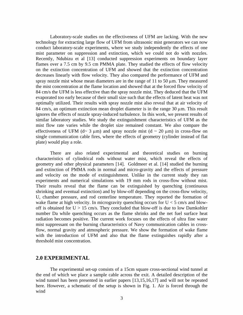
The experimental set-up consists of a 15cm square cross-sectional wind tunnel at the end of which we place a sample cable across the exit. A detailed description of the wind tunnel has been presented in earlier papers [13,15,16,17] and will not be repeated here. However, a schematic of the setup is shown in Fig. 1. Air is forced through the wind

Plenum
AirAir+ mist
Variable speed blower
water
Air
Regulator
Compressed air
Pressure gauge
Spray nozzle
Air
Mist
Ultrasonic Mister
Air
60 cm mist injection section
Small Pilot burner (diameter d)
5d
Cable (bundle)
wakeFlame
Mist injection section
Figure 1: Schematic of the Experimental setup. Insert shows the setup with NanoMist System’s ultra fine mist generator
4
5
tunnel at a constant flow rate perpendicular to the axis of the cable. Fine water droplets are introduced 100 cm upstream from the tunnel exit such that they will be carried by and dispersed in the air before encountering the flame. For tests with spray nozzle mist, droplets are produced by forcing distilled water at a constant pressure in a 9.4-liter tank through a spray nozzle at the center of the tunnel. 2.1 Mist Generation and Characterization
The ultra fine mist (UFM) was produced with ultrasonic mist generators built by Nanomist Systems P
®P.P
PThe droplets are generated by ultrasonic vibration of piezoelectric
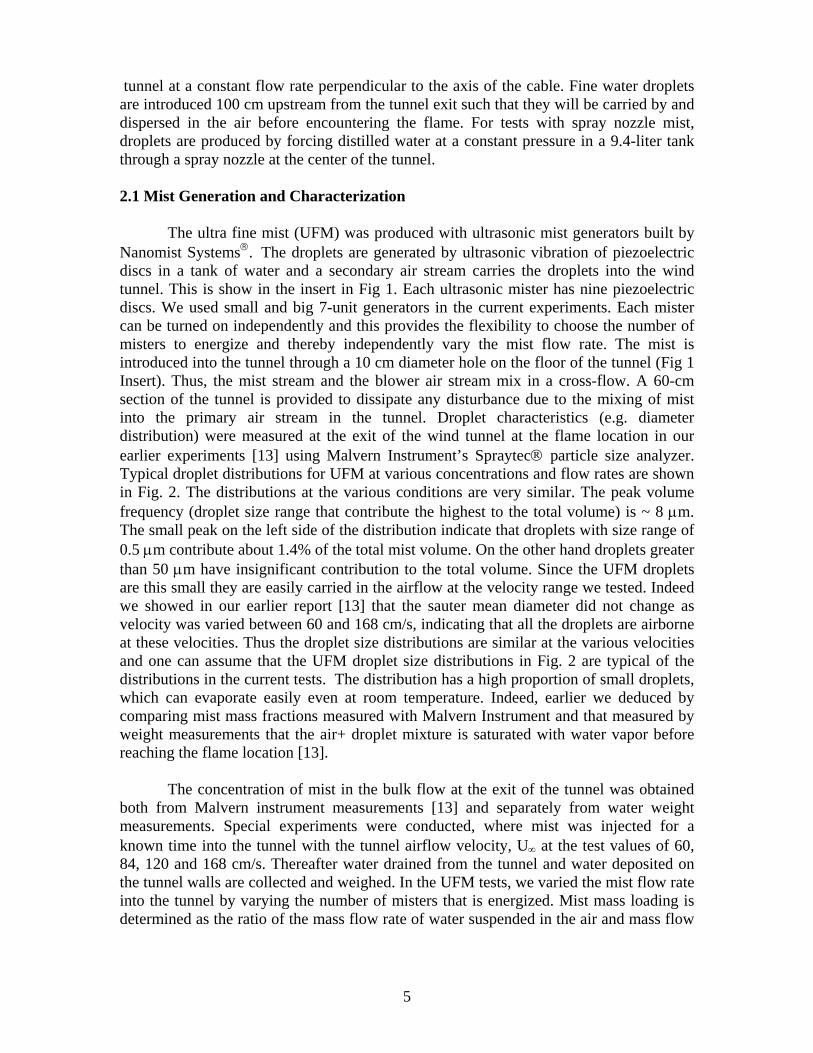
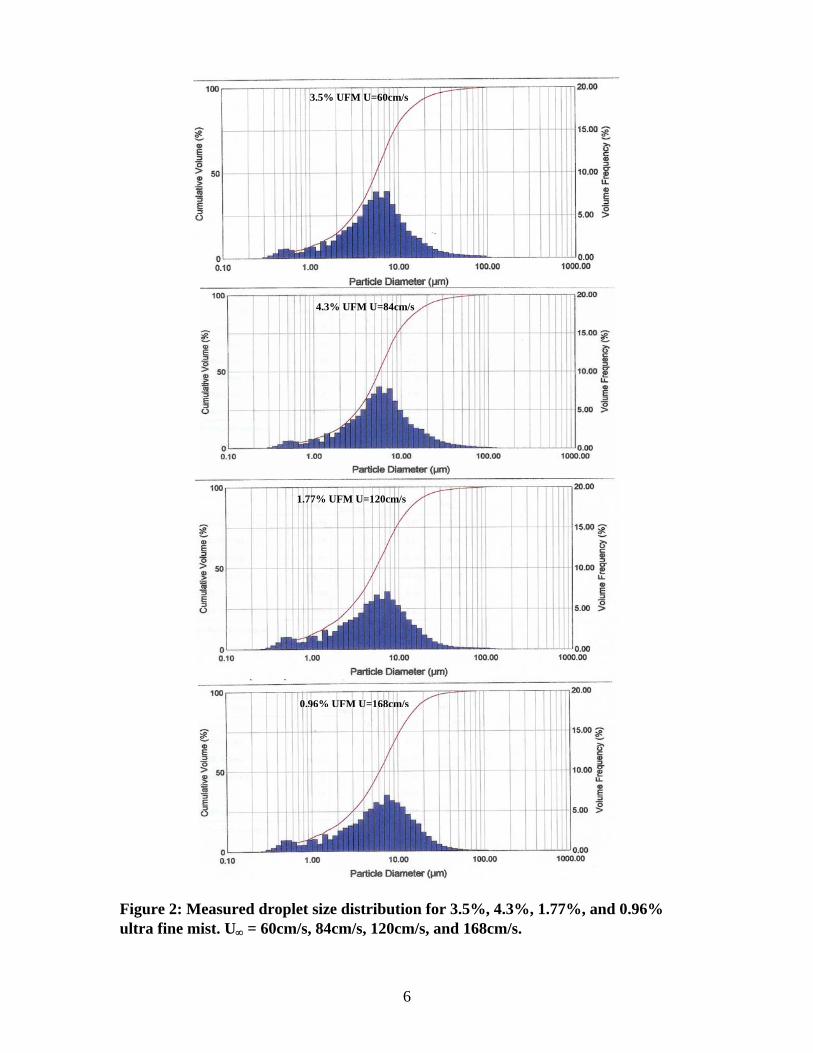
discs in a tank of water and a secondary air stream carries the droplets into the wind tunnel. This is show in the insert in Fig 1. Each ultrasonic mister has nine piezoelectric discs. We used small and big 7-unit generators in the current experiments. Each mister can be turned on independently and this provides the flexibility to choose the number of misters to energize and thereby independently vary the mist flow rate. The mist is introduced into the tunnel through a 10 cm diameter hole on the floor of the tunnel (Fig 1 Insert). Thus, the mist stream and the blower air stream mix in a cross-flow. A 60-cm section of the tunnel is provided to dissipate any disturbance due to the mixing of mist into the primary air stream in the tunnel. Droplet characteristics (e.g. diameter distribution) were measured at the exit of the wind tunnel at the flame location in our earlier experiments [13] using Malvern Instrument’s Spraytec® particle size analyzer. Typical droplet distributions for UFM at various concentrations and flow rates are shown in Fig. 2. The distributions at the various conditions are very similar. The peak volume frequency (droplet size range that contribute the highest to the total volume) is ~ 8 µm. The small peak on the left side of the distribution indicate that droplets with size range of 0.5 µm contribute about 1.4% of the total mist volume. On the other hand droplets greater than 50 µm have insignificant contribution to the total volume. Since the UFM droplets are this small they are easily carried in the airflow at the velocity range we tested. Indeed we showed in our earlier report [13] that the sauter mean diameter did not change as velocity was varied between 60 and 168 cm/s, indicating that all the droplets are airborne at these velocities. Thus the droplet size distributions are similar at the various velocities and one can assume that the UFM droplet size distributions in Fig. 2 are typical of the distributions in the current tests. The distribution has a high proportion of small droplets, which can evaporate easily even at room temperature. Indeed, earlier we deduced by comparing mist mass fractions measured with Malvern Instrument and that measured by weight measurements that the air+ droplet mixture is saturated with water vapor before reaching the flame location [13].
The concentration of mist in the bulk flow at the exit of the tunnel was obtained
both from Malvern instrument measurements [13] and separately from water weight measurements. Special experiments were conducted, where mist was injected for a known time into the tunnel with the tunnel airflow velocity, UB∞ B at the test values of 60, 84, 120 and 168 cm/s. Thereafter water drained from the tunnel and water deposited on the tunnel walls are collected and weighed. In the UFM tests, we varied the mist flow rate into the tunnel by varying the number of misters that is energized. Mist mass loading is determined as the ratio of the mass flow rate of water suspended in the air and mass flow
6
Figure 2: Measured droplet size distribution for 3.5%, 4.3%, 1.77%, and 0.96% ultra fine mist. UB∞ B = 60cm/s, 84cm/s, 120cm/s, and 168cm/s.
3.5% UFM U=60cm/s
4.3% UFM U=84cm/s
1.77% UFM U=120cm/s
0.96% UFM U=168cm/s
7
rate of air. These data include the contribution from water vapor unlike the Malvern Instrument measurements, which do not detect water vapor. Therefore, mass loading measured from weight measurements were used in all the analysis in this paper. Table 1 lists the measured mist parameters at the various test conditions
Larger droplet mist was generated with Delavan’s WDBP
®P nozzles and Spray
System’s Cold Fog® spray nozzles. At the pressure of 44.8 bar (650 psi) these nozzles produce fine water sprays with SMD of the order of 20 µm. Spray nozzle mist characteristics were also measured in our earlier experiment [13]. The droplet mean diameters (d) were measured at much lower pressures 2.8 and 5.2 bar (40 and 75 psi) and the diameters at the current pressure (p) of 44.8 bar (650 psi) were estimated since d ∝ pP
-
0.3P [9]. This estimate is good enough for the present analysis. We ran experiments at 44.8
bar (650 psi) in order to obtain high mist flow rates. The measured and extrapolated droplet sizes as well as the weight-measured concentrations are shown in Table 1. 2.2 Test Procedure
We conducted preliminary tests with Navy power, communication and control cables and found that the power and control cables do not readily burn without the pilot flame but the communication cables do. This confirms the findings of Alexander et al [6]. Pictures of the power and control cables after unsuccessful attempts to ignite them are shown in Fig. A1 in the Appendix.
20-cm lengths of Navy communication cable were burned at the exit of the tunnel
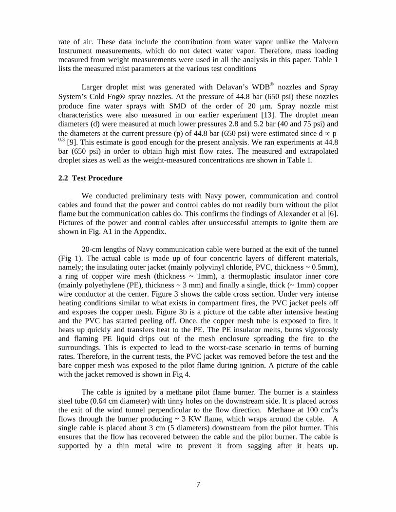
(Fig 1). The actual cable is made up of four concentric layers of different materials, namely; the insulating outer jacket (mainly polyvinyl chloride, PVC, thickness ~ 0.5mm), a ring of copper wire mesh (thickness ~ 1mm), a thermoplastic insulator inner core (mainly polyethylene (PE), thickness ~ 3 mm) and finally a single, thick (~ 1mm) copper wire conductor at the center. Figure 3 shows the cable cross section. Under very intense heating conditions similar to what exists in compartment fires, the PVC jacket peels off and exposes the copper mesh. Figure 3b is a picture of the cable after intensive heating and the PVC has started peeling off. Once, the copper mesh tube is exposed to fire, it heats up quickly and transfers heat to the PE. The PE insulator melts, burns vigorously and flaming PE liquid drips out of the mesh enclosure spreading the fire to the surroundings. This is expected to lead to the worst-case scenario in terms of burning rates. Therefore, in the current tests, the PVC jacket was removed before the test and the bare copper mesh was exposed to the pilot flame during ignition. A picture of the cable with the jacket removed is shown in Fig 4.
The cable is ignited by a methane pilot flame burner. The burner is a stainless
steel tube (0.64 cm diameter) with tinny holes on the downstream side. It is placed across the exit of the wind tunnel perpendicular to the flow direction. Methane at 100 cmP
3P/s
flows through the burner producing ~ 3 KW flame, which wraps around the cable. A single cable is placed about 3 cm (5 diameters) downstream from the pilot burner. This ensures that the flow has recovered between the cable and the pilot burner. The cable is supported by a thin metal wire to prevent it from sagging after it heats up.

8
Mist Generator
Diameter at peak volume frequency (µm)
Peak Volume Frequency (%)
Sauter Mean diameter (µm)
Extrapolated Sauter Mean diameter (µm)
% Mist mass loading (Wt measurement)
UFM generator, 3
small misters
7.92 8 3.15 - 3.3
- 7 small misters
7.0
- 2 big misters
7.9
- 3 big misters
10.0
- 5 big misters
14.6
- 7 big misters
18.5
Delavan 1 Nozzle
(U=84 cm/s)
63 12.9 47.35 (40psi)
20.5 (650 psi)
5.8
- 2 Nozzles 10.69 Spray
System 1 nozzle
47.78 15.6 38.28 20.7 (650 psi)
3.95
- 2 nozzles 11.2
Table1: Measured and extrapolated mist parameters. U= 60 cm/s.
Fig
Ring of copperwire mesh
P
u
Outer jacket(PVC)
Figure 3a: Cross section of the Navy communication cable
E
re 3b: The cable after exposure to int
9
Copper conductorwire
Polyethylene (PE) insulator
Exposed Copper mesh
ense heat

Figure 4: Picture of the cable with the PVC jacket removed
10

11
To start the experiment, the blower is turned on and the airflow is adjusted to the
required air velocity as measured by a hot wire anemometer. The pilot flame is ignited and it wraps around the cable of known initial weight. The stopwatch is started as the pilot flame is ignited. As the flame heats up the cable, the polyethylene melts and pyrolyzes, producing gases, which are ignited by the pilot flame. After the pilot flame burns for 1.5 min it is turned off and a stable self-sustaining flame wraps around the cable at low airflow velocities. In tests with water mist the misters are energized at this time and the incoming mist suppresses and eventually extinguishes the cable flame. Extinguishment time in tests with and without mist is the time the last bit of the flame goes off as determined visually using the stopwatch. The burned sample is weighed after it cools down and the total weight burned is obtained as the difference between the initial and final weights. In separate tests, the sample weights are also measured before and after the 1.5 min pilot ignition period, so that the weight burned during ignition can be obtained and subtracted out. Thus, the actual self-sustained burning rate, burn time and fraction of the original sample burned can be determined.
As mist stream encounters the burning cable the flame extinguishes locally at the
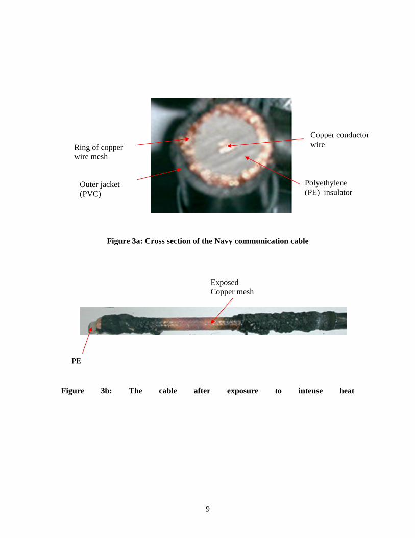
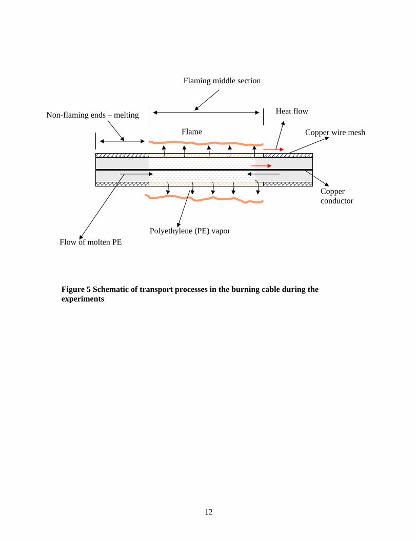
front stagnation point and re-attaches along the circumference forming a quench zone. The originally envelope flame now becomes a wake flame, whose size shrinks with time. A set of five R-type, 125 µm-diameter, bare-wire thermocouples were lined up behind the cable along the center-stagnation point line. The thermocouples measure the temperatures with time, which are used to study how fast the water mist cools the wake flame and eventually extinguishes it. The thermocouples were placed 1, 6, 11, 16 and 21 mm from the cable rear surface. Although finer thermocouples would measure the temperatures more accurately, they are not rigid enough for the precise close arrangement required in this setup. Indeed we showed in earlier reports [16] that temperatures measured with 125 µm diameter thermocouple in PMMA boundary layer flames were about 200 K less than those measured with the 50 µm-diameter thermocouples at the same location. Therefore the temperatures reported in this study are to be used for qualitative rather than quantitative comparisons. 3.0 RESULTS AND DISCUSSION Figure 5 illustrates the heat and mass transfer processes that take place in the communication cable burning in cross-flow. The flame heats up the copper metal sieve around the cable, which in turn heats the polyethylene (PE) insulation. As the PE core is heated it softens and melts. At the pyrolysis temperature of about 650 K, the PE crosslink decomposes to produce hydrocarbon gases, which escape through the metal sieve and mix with the airflow and burn. Some of the melt drips through the metal sleeve initially. The copper mesh conducts heat from the flaming part of the cable to the virgin ends. Heat is also conducted towards the ends by the solid copper conductor in the middle of the cable. Since copper is a very good conductor, the rapid heat flow towards the ends of the cable helps spread the flame outwards and it is also expected to give rise to an inward flow of molten PE as illustrated in Fig. 5. If the PE burns faster than it is being
Flaming middle section
Non-flaming ends – melting
Flow of molten PE Polyethylene (PE) vapor
Copper wire mesh Flame
Copper conductor
Heat flow
Figure 5 Schematic of transport processes in the burning cable during the experiments
12
13
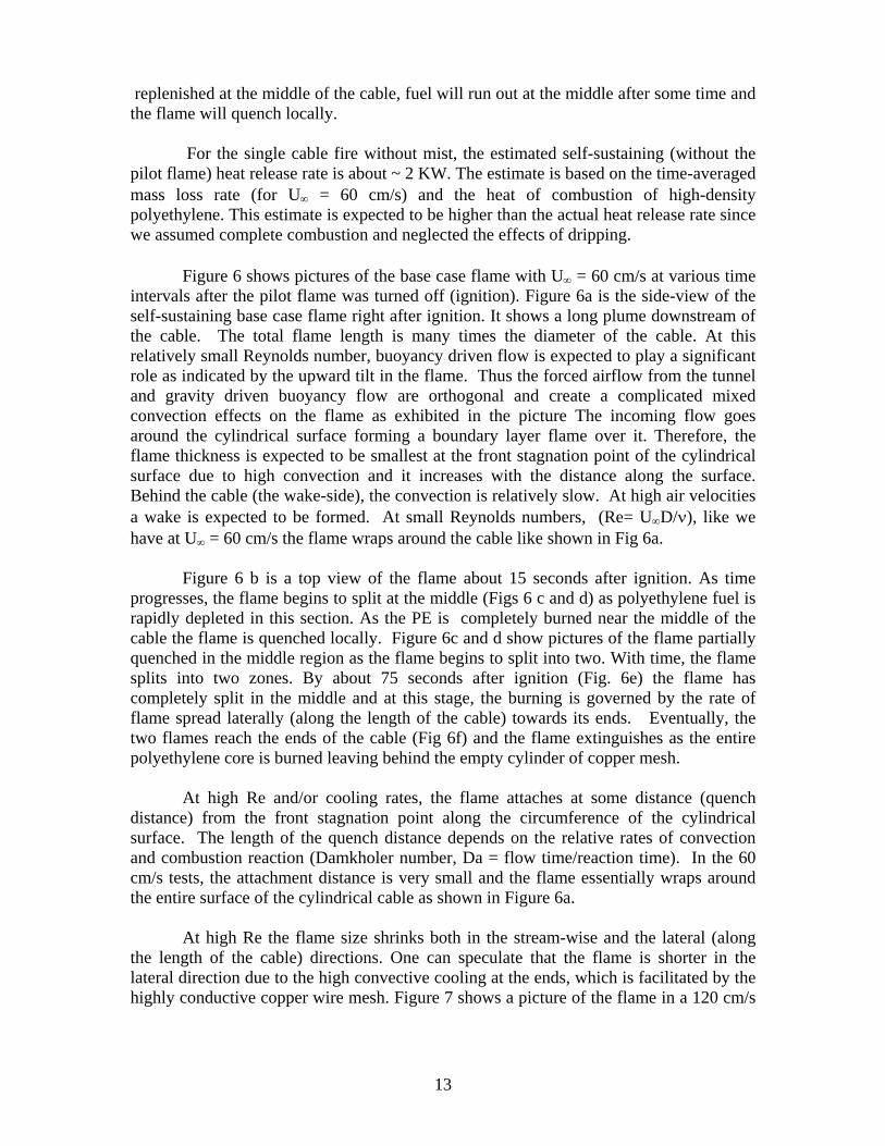
replenished at the middle of the cable, fuel will run out at the middle after some time and the flame will quench locally.
For the single cable fire without mist, the estimated self-sustaining (without the pilot flame) heat release rate is about ~ 2 KW. The estimate is based on the time-averaged mass loss rate (for UB∞ B = 60 cm/s) and the heat of combustion of high-density polyethylene. This estimate is expected to be higher than the actual heat release rate since we assumed complete combustion and neglected the effects of dripping.
Figure 6 shows pictures of the base case flame with UB∞ B = 60 cm/s at various time
intervals after the pilot flame was turned off (ignition). Figure 6a is the side-view of the self-sustaining base case flame right after ignition. It shows a long plume downstream of the cable. The total flame length is many times the diameter of the cable. At this relatively small Reynolds number, buoyancy driven flow is expected to play a significant role as indicated by the upward tilt in the flame. Thus the forced airflow from the tunnel and gravity driven buoyancy flow are orthogonal and create a complicated mixed convection effects on the flame as exhibited in the picture The incoming flow goes around the cylindrical surface forming a boundary layer flame over it. Therefore, the flame thickness is expected to be smallest at the front stagnation point of the cylindrical surface due to high convection and it increases with the distance along the surface. Behind the cable (the wake-side), the convection is relatively slow. At high air velocities a wake is expected to be formed. At small Reynolds numbers, (Re= UB∞ BD/ν), like we have at UB∞ B = 60 cm/s the flame wraps around the cable like shown in Fig 6a. Figure 6 b is a top view of the flame about 15 seconds after ignition. As time progresses, the flame begins to split at the middle (Figs 6 c and d) as polyethylene fuel is rapidly depleted in this section. As the PE is completely burned near the middle of the cable the flame is quenched locally. Figure 6c and d show pictures of the flame partially quenched in the middle region as the flame begins to split into two. With time, the flame splits into two zones. By about 75 seconds after ignition (Fig. 6e) the flame has completely split in the middle and at this stage, the burning is governed by the rate of flame spread laterally (along the length of the cable) towards its ends. Eventually, the two flames reach the ends of the cable (Fig 6f) and the flame extinguishes as the entire polyethylene core is burned leaving behind the empty cylinder of copper mesh.
At high Re and/or cooling rates, the flame attaches at some distance (quench
distance) from the front stagnation point along the circumference of the cylindrical surface. The length of the quench distance depends on the relative rates of convection and combustion reaction (Damkholer number, Da = flow time/reaction time). In the 60 cm/s tests, the attachment distance is very small and the flame essentially wraps around the entire surface of the cylindrical cable as shown in Figure 6a.
At high Re the flame size shrinks both in the stream-wise and the lateral (along
the length of the cable) directions. One can speculate that the flame is shorter in the lateral direction due to the high convective cooling at the ends, which is facilitated by the highly conductive copper wire mesh. Figure 7 shows a picture of the flame in a 120 cm/s
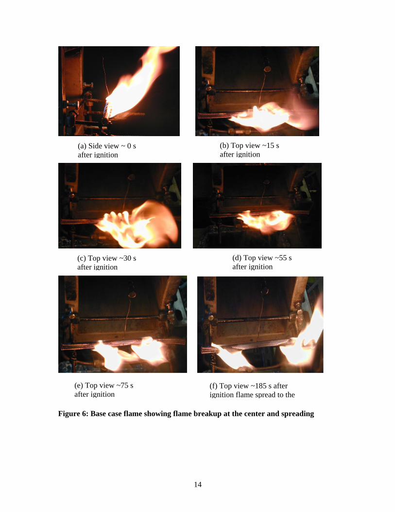
Figure 6: Base case flame showing flame breaku
14
(b) Top view ~15 safter ignition
(c) Top view ~30 s after ignitionp at
(d) Top view ~55 s after ignition
(e) Top view ~75 safter ignition(f) Top view ~185 s after ignition flame spread to the
(a) Side view ~ 0 safter ignition
the center and spreading
15
base case test right after ignition. It shows that the quench distance is large, nearly the entire front half of the circumference. Thus significant pyrolysis takes place only in the rear half of the cable circumference, which is covered by the flame. Since the total heat transfer to the PE fuel is less because of the smaller exposed surface area, the fuel gasification rate is expected to be lower and this results in a shorter flame length. In the lateral direction, the copper mesh at both ends is cooled rapidly by high convective flow and so heat transfer to virgin PE is suppressed and lateral flame spread is suppressed. Thus flaming takes place only in the middle section as Figs 7 a to d show and the flame does not split in the middle like in Fig 6. Because of the high lateral cooling, the melting and inward flow of PE (Fig 5) is expected to be minimal and the flame is extinguished as the PE fuel is burned in the middle region of the cable. Thus the base case flame is extinguished by high convective cooling without burning the entire PE. Indeed, the flame burn-time is much less (~ 4 times less) at high velocity than at low velocity. Burn-time is the total time the cable burned after the pilot flame was extinguished.
The copper mesh plays an important role in the burning of the cable. At high UB∞ B
it conducts heat from the rear half of the circumference, where the flame is to the front stagnation region. It also conducts heat along the length of the cable to pre-heat and melt the PE core. This enhances lateral flame spread at low UB∞ B,B Bas was the case in the 60 cm/s test. At high velocities, however the exposed copper mesh is cooled rapidly by convection and pre-heating and melting of the virgin PE is greatly suppressed, as was the case in Fig.7. Overall, the copper mesh is expected to enhance the burning rate of the cable without mist at low velocities and have the opposite effect at high velocities. Indeed, the middle region of the cable ran out of fuel in about 74 s at 120 cm/s (Fig. 7f). This is close to the time the PE was exhausted in the middle of the cable in the 60 cm/s test (Fig.6d,e). However, the flame continues to spread laterally and the entire 20-cm length of the cable ran out of fuel after about 3 minutes in the 60 cm/s test (Fig. 6f).
The observed trends in the tests with Navy communication cable are qualitatively similar to those described in the experiments and calculations performed by Goldmeer et al. [14] on the burning and extinction of poly methyl methacrylate (PMMA) cylinders in a space shuttle at low gravity. The cylinders do not have the metal mesh like the Navy cables. They showed that the flame attaches away from the front stagnation point of the cylinder at high velocities and forms a wake flame behind the cylinder. The local burning rate is expected to vary along the circumference of the cylinder. The visible flame length and width are of the order of the cylinder diameter (1.9 cm) at atmospheric pressure and air velocity of 10 cm/sec. As the velocity of the forced air is reduced, they predicted that the flame recedes away from the wake region towards the front stagnation point, and finally quenches at around 5-cm/sec-air velocity. As the air velocity is increased, however, their model predicts that the flame recedes away from the front stagnation point towards the back of the cylinder forming a quench distance. As air velocity increases beyond a threshold value, the flame extinguishes by blow-off.
The burning characteristics of cylindrical rods in cross-flow without metal mesh
at normal gravity is not yet well understood. It is expected to be significantly different from that of a flat plate, which has been relatively well studied. Recently, Ndubizu et al.
16
(a) 9s after ignition (b) 18s after ignition
(c) 38s after ignition (d) 51s after ignition
(e) 62s after ignition (f) 74s after ignition Figure 7: Base Case flame at various times with UB∞ B120cm/s
.
17
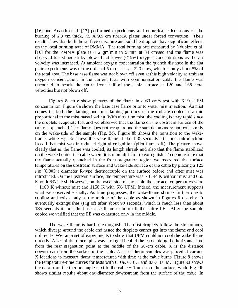
[16] and Ananth et al. [17] performed experiments and numerical calculations on the burning of 2.3 cm thick, 7.5 X 9.5 cm PMMA plates under forced convection. Their results show that both the surface curvature and solid heat-up rate have significant effects on the local burning rates of PMMA. The total burning rate measured by Ndubizu et al. [16] for the PMMA plate is ~ 2 gm/min in 5 min at 84 cm/sec and the flame was observed to extinguish by blow-off at lower (<19%) oxygen concentrations as the air velocity was increased. At ambient oxygen concentration the quench distance in the flat plate experiments was of the order of 5 mm at UB∞ B = 220 cm/s, which is only about 5% of the total area. The base case flame was not blown off even at this high velocity at ambient oxygen concentration. In the current tests with communication cable the flame was quenched in nearly the entire front half of the cable surface at 120 and 168 cm/s velocities but not blown off.
Figures 8a to e show pictures of the flame in a 60 cm/s test with 6.1% UFM
concentration. Figure 8a shows the base case flame prior to water mist injection. As mist comes in, both the flaming and non-flaming portions of the rod are cooled at a rate proportional to the mist mass loading. With ultra fine mist, the cooling is very rapid since the droplets evaporate fast and we observed that the flame on the upstream surface of the cable is quenched. The flame does not wrap around the sample anymore and exists only on the wake-side of the sample (Fig. 8c). Figure 8b shows the transition to the wake-flame, while Fig. 8c shows the wake-flame at about 35 seconds after mist introduction. Recall that mist was introduced right after ignition (pilot flame off). The picture shows clearly that as the flame was cooled, its length shrank and also that the flame stabilized on the wake behind the cable where it is more difficult to extinguish. To demonstrate that the flame actually quenched in the front stagnation region we measured the surface temperatures on the upstream surface and wake-side surface of the cable by placing a 125 µm (0.005”) diameter R-type thermocouple on the surface before and after mist was introduced. On the upstream surface, the temperature was ~ 1144 K without mist and 660 K with 6% UFM. However, on the wake side of the cable the surface temperatures were ~ 1160 K without mist and 1150 K with 6% UFM. Indeed, the measurement supports what we observed visually. As time progresses, the wake-flame shrinks further due to cooling and exists only at the middle of the cable as shown in Figures 8 d and e. It eventually extinguishes (Fig 8f) after about 90 seconds, which is much less than about 185 seconds it took the base case flame to burn off the entire PE. After the sample cooled we verified that the PE was exhausted only in the middle.
The wake flame is hard to extinguish. The mist droplets follow the streamlines,
which diverge around the cable and hence the droplets cannot get into the flame and cool it directly. We ran a set of experiments to show that UFM could not cool the wake flame directly. A set of thermocouples was arranged behind the cable along the horizontal line from the rear stagnation point at the middle of the 20-cm cable. X is the distance downstream from the surface of the cable. A set of thermocouples was placed at various X locations to measure flame temperatures with time as the cable burns. Figure 9 shows the temperature-time curves for tests with 0.0%, 6.16% and 8.6% UFM. Figure 9a shows the data from the thermocouple next to the cable ~ 1mm from the surface, while Fig. 9b shows similar results about one-diameter downstream from the surface of the cable. In

(a) ~ BC flame before mist 15 sec later (b) ~15 sec after mist
(e) Top view ~ 40 sec after mist Burning in the middle only
(c ) ~ 35 sec after mist
(e) ~ 90 sec after mist (Extinguishment)
(d) ~ 80 sec after mist
Figure 8: Effects of 6% ultra fine mist on the cable flame
18

19
the base case (0.0% mist) tests the flame temperature decreases very rapidly after about 50 seconds. This is the time the flame quenches locally at the middle and splits into two. Prior to this time the temperatures are not significantly different in tests with and without mist. This is a clear indication that UFM droplets have difficulty getting into the wake flame and cool it directly. In the mist tests the temperatures decrease more slowly after about 50 seconds, more so for the 8.6% mist test than for the 6.16 % mist case. In the mist tests, the temperature values for t > 50s in Figs. 9a and b reflect the fact that the wake flame shrinks in size with time and eventually extinguishes. Extinguishment here is by flame shrinking unlike the in our earlier tests [13] with PMMA flat plate, where extinguishment by water mist is by flame blow-off. In that case mist could reach the flame attachment location and cool it rapidly such that the local Da is reduced below the critical value. In the present case with cables, the flame is attached on the wake side of the cable, where the droplets could not reach.
As we showed in the base case test, the PE fuel depletes rapidly as the flame
burns. However, in the presence of mist, the flame does not split at the middle of the sample and spread along the length of the cable as was the case in Figs. 6. This is due to the rapid cooling effects on the virgin cable due to the presence of UFM. In the mist tests the burning is confined mainly to the middle region of the cable. The presence of the copper mesh, enhances heat removal from the flame, which contributes to suppression in both burning rate and flame spread. Thus, the burning rate is smaller with UFM than the base case and it takes longer for the PE to run out at the middle of the cable with mist than that without mist as Fig. 9 shows. For example, the flame begins to split after about 55 seconds in the base case as the fuel runs out in the middle region of the cable as shown in Fig. 6d, while the flame continues to burn at the middle of the cable up to 80 seconds in the presence of mist as shown in Fig. 8d.
To show quantitatively that copper wire mesh enhanced UFM flame extinguishment, we ran some experiments with 12.5 mm diameter cast, unpolished poly methylmethacrylate (PMMA) rods and also with the same rods with copper wire mesh wrapped around them. The copper wire mesh used in these tests was the mesh left behind after the PE burned off in the base case cable experiments. Figure 10 shows pictures of the plain PMMA rod, the wrapped PMMA rod and the wrapped PMMA rod burning without mist. Several tests were conducted with the wrapped and unwrapped rod with UB∞ B = 60 cm/s and UFM concentration varying between 0 and 18%. Table 2 shows the burn-time at various levels of mist concentration. It shows that without the copper mesh the flame could not be extinguished even at mist concentration as high as 18%. In this experiment we poured cold water over the sample to extinguish the flame after 10 minutes. However with the wire mesh the flame was extinguished with UFM concentrations as small as 4.1 % mist. Table 2 shows that the time to extinguishment decreases as mist concentration increases. For example, with 18% mist the flame over the wrapped rod experiment was extinguished in about 33 seconds, however with 7.9% mist the flame was extinguished in about 53 seconds. These results would lead one to conclude that the copper wire mesh enhanced the suppression effectiveness of the UFM in the current tests with Navy communication cable .

0
200
400
600
800
1000
1200
1400
1600
0 20 40 60 80 100
Time (s)
Tem
pera
ture
(K)
0% mist6.16% mist8.6% mist
e
e
0
200
400
600
800
1000
1200
1400
1600
0 20 40 60 80 100
Time (s)
Tem
pera
ture
(K)
BC6.16%8.60%
Figure 9: Temperature versus time along the center of the wake flame at 0, 6.1 and 8.6% mist concentrations, U = 60 cm/s – (a) X ~ 1 mm from the surface and (b) X ~ 1d from the surface
20
X
Flam
Cabl
(a)
(b)

(a)
(b)
(c)
Figure 10: Pictures of (a) black PMMA rod (b) PMMA rod wrapped with copper
wire mesh and (c) Wrapped PMMA rod burning in air at 60 cm/s without mist
21

22
Table 2: The effects of copper wire mesh on the extinguishment of 12.5 mm diameter PMMA rods
Sample UFM mass fraction (%)
Time to Extinguishment after mist is introduced (s)
PMMA rod – no Cu wire 18 Still flaming after 600 s PMMA rod with Cu wire mesh
wrapped over it 18 33
14.6 33 10 57 7.9 53 4.1 142
23
The data in Table 2 can be used to show the effects of geometry on UFM
effectiveness. In our earlier work [13] we showed that at air velocity of 60 cm/s, about 6.8% UFM is needed to extinguish (by blow-off) a PMMA flat plate flame. However, Table 2 shows that 18% UFM could not extinguish a 12.5-cm diameter PMMA rod flame. The introduction of mist led to the formation of a wake flame (Fig. 8), which is difficult to extinguish. Thus, the effects of geometry (plate versus cylinder) on the extinguishment concentration are very significant.
Water mist fire suppression studies of burning cylinders are sparse. Tsa et al. [18]
performed theoretical calculations of water mist suppression of a diffusion flame formed on a cylindrical Tsuji burner under forced convection. They found that the introduction of water mist causes the flame to transform from an envelope flame that engulfs the cylinder to a wake flame. As a result of mist cooling, the flame is quenched in the front half of the cylinder circumference, similar to what we observed in the current experiments. Further theoretical work is needed to quantify the mechanisms of mist suppression of flame over cylindrical objects.
Water mist suppression effectiveness is often quantified in terms of suppression in
burning rate [19], reduction in burn-time [20] or reduction in the fraction of original sample burned [21]. In the current experiments with 20 cm long, 0.95 cm diameter cable only about 30 % of the sample is combustible. The sample is heated by a pilot flame, which wraps around it for 1.5 minutes. The heat melts and pyrolyzes the PE and the vapor is ignited by the pilot flame. As the PE melts some of it drips from the cable without burning. As a result of this, the self-sustained combustion lasts a short time since the fuel content of the sample is small and all of it is warmed during ignition. Therefore the time-averaged burning rate has considerable uncertainty. We therefore, quantified mist effectiveness in terms of the fraction of original sample burned and the burn time after ignition. Next we present the effects of UFM concentration in the airflow on burn time and fraction of sample burned in tests where the droplet diameter is held constant.
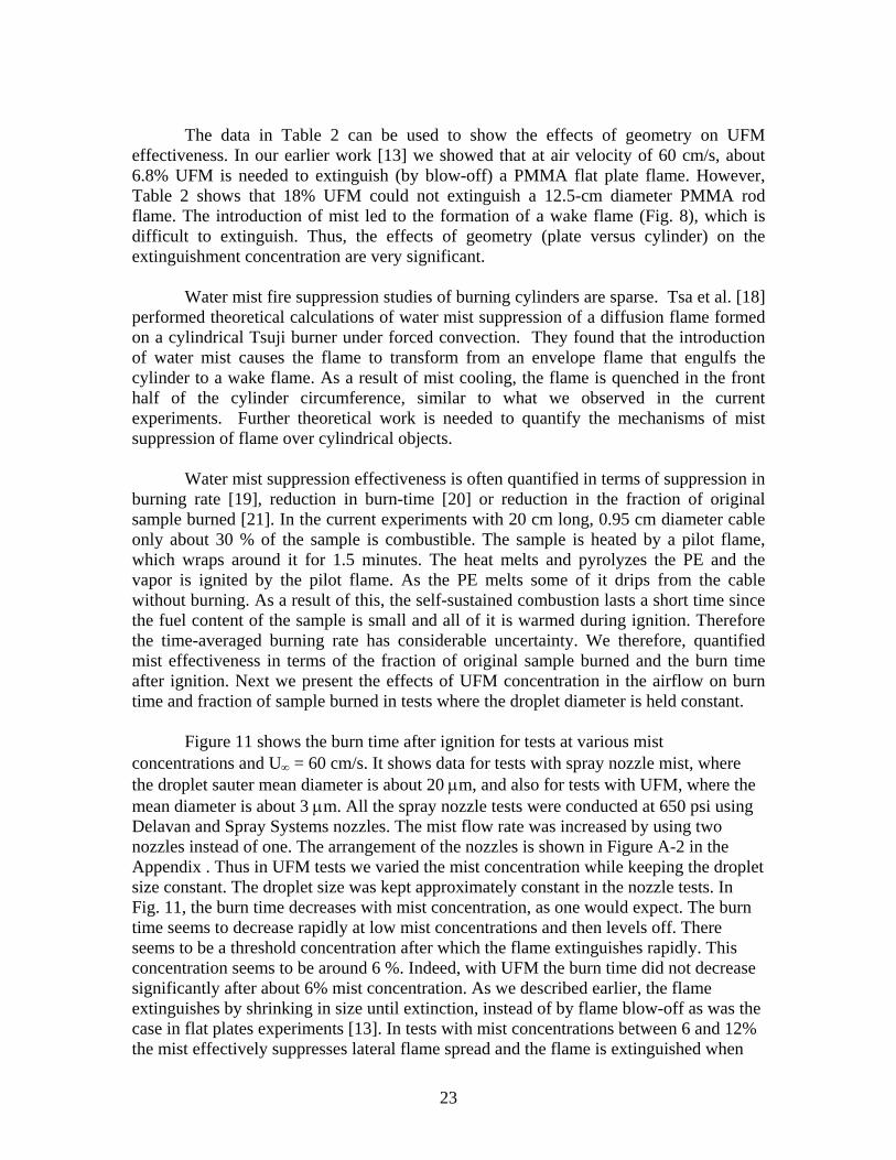
Figure 11 shows the burn time after ignition for tests at various mist
concentrations and UB∞ B = 60 cm/s. It shows data for tests with spray nozzle mist, where the droplet sauter mean diameter is about 20 µm, and also for tests with UFM, where the mean diameter is about 3 µm. All the spray nozzle tests were conducted at 650 psi using Delavan and Spray Systems nozzles. The mist flow rate was increased by using two nozzles instead of one. The arrangement of the nozzles is shown in Figure A-2 in the Appendix . Thus in UFM tests we varied the mist concentration while keeping the droplet size constant. The droplet size was kept approximately constant in the nozzle tests. In Fig. 11, the burn time decreases with mist concentration, as one would expect. The burn time seems to decrease rapidly at low mist concentrations and then levels off. There seems to be a threshold concentration after which the flame extinguishes rapidly. This concentration seems to be around 6 %. Indeed, with UFM the burn time did not decrease significantly after about 6% mist concentration. As we described earlier, the flame extinguishes by shrinking in size until extinction, instead of by flame blow-off as was the case in flat plates experiments [13]. In tests with mist concentrations between 6 and 12% the mist effectively suppresses lateral flame spread and the flame is extinguished when

0
50
100
150
200
250
0 2 4 6 8 10 12 14 16 18
Mist mass fraction (%)
Bur
n-tim
e (s
)
UFM Spray Nozzle Mist
Figure 11: Comparison of burn times in tests with ultra fine mist and spray nozzle mist at various mist concentrations. U = 60 cm/s
24

25
the PE is burned out in the middle of the cable. In these cases the UFM extinguished the flame two times faster than the spray nozzle mist. For example the UFM extinguishes the flame in the order of 40 seconds, while nozzle mist extinguishes it in about 90 seconds. At higher concentrations of UFM, the flame is extinguished before the PE is all burned in the middle of the sample and in these cases the flame is extinguished within about 25 seconds. The results show that UFM is more effective in extinguishing the single cable fire in cross-flow than the nozzle mist. At 60 cm/s the UFM flow was laminar and therefore only the effects of the mist concentration were shown in Fig. 11. However, with the nozzles running at 650 psi, the resulting mist had significant induced turbulence. Therefore, spray-induced turbulence probably contributed to the effects shown in Fig. 11. Earlier, Ndubizu et al [13] had reported that the effects of spray-induced turbulence significantly affected the local burning rate of a PMMA flat plate, especially downstream.
The mist concentrations reported in Fig. 11 are the concentrations at the flame
location. Recall that the mist was injected about 100 cm upstream from the exit of the tunnel. However not all the droplets injected into the tunnel 100 cm upstream are suspended in the air at the flame location. For the UFM about 92% of the mist input was carried in the air to the flame location [13]. On the other hand, with the Delavan and Spray Systems nozzles running at 650 psi and mist mass loading of ~ 10%, our measurements show that only about 19% and 50%, respectively, of input droplets are airborne at the flame location. Thus UFM droplets are easily carried by the airflow and the use of UFM for fire suppression would lead to much less water damage than spray mist in sub-floors and electronic spaces.
The above results, which compared the effectiveness of spray nozzle mist (~ 20
µm) and UFM (~3 µm) are rather contradictory with the results of the numerical calculations performed by Tsa et al. [18]. They modeled the suppression of a gaseous diffusion flame on a Tsuji burner. They varied the size of the mist droplets and their model predicts that the large droplets are more effective than small droplets in extinguishing the cylindrical flame. They showed that with 50 µm droplets, 7% mist is needed to suppress the envelope flame and form a wake flame, and 15% mist is needed to completely extinguish the wake flame. As the droplet size is increased to 80 µm, they predicted that 4.5 % mist is needed to suppress the envelope flame and form the wake flame, while 10% mist is needed for extinguishment. Our measurements on the other hand, show that the UFM is more effective than the larger spray nozzle droplets. Although the droplet range in Tsa’s work are different from the range in the current work, the nozzle spray induced turbulence and the presence of the copper mesh could have contributed to the difference between the two results. Clearly, further work is needed to understand the droplet size effects on the water mist suppression of burning cables.
Figure 12 shows the effects of velocity on the burn time at various mist
concentrations. We present results for UFM only. The results were obtained with one unit of NanoMist Systems’s UFM generator. In these tests, the mean droplet diameter remained constant as the velocity increases since the droplet distribution as measured with the Malvern Instrument did not change with velocity as Fig. 2 indeed shows. This is

0
20
40
60
80
100
120
140
160
180
200
0 5 10 15 20
Mist Mass Fraction (%)
Bur
n-Ti
me
(s)
U = 60 cm/sU= 84U = 120U = 168
Figure 12: The effects of velocity on the burn time at various mist concentrations
26
27
because the distribution is made up of droplets less than 50 µm in diameter and at 60 cm/s, the air easily carries even the larger members. Thus, in these tests the mist concentration was varied independent of the droplet size. This is a flexibility, which we did not have with nozzles. With the nozzles on the other hand, we showed [13] that the mean droplet size increased with velocity. This is because the droplet distributions have a significant population of very large droplets and the drag on them could not overcome gravity at low air velocities.
In tests without mist (0% mist in Fig. 12), two things happen at 120 and 168 cm/s.
First a quench zone is formed, which is comparable in area to the total heat transfer area of the cable. Secondly, the flame standoff distance decreases and hence heat transfer to the solid and consequently the PE pyrolysis rate increases. In addition the copper mesh enhances heat losses from the flame to the ambient as discussed earlier. Thus at 0% mist concentration (base case), the flame is extinguished nearly 3 times faster at 168 cm/s than at 60 cm/s. In the 60 cm/s test the flame spreads laterally and the entire combustible PE is burned when the flame extinguishes. However, in the 168 cm/s test, the flame could not spread laterally because of high cooling and therefore extinction occurs as the PE is burned in the middle section. This will be shown more clearly in the next section where we present the result in terms of percent of the available PE fuel burned. As the mist concentration increases, Fig 12 shows that the cooling effects increase and the burn time decreases. The cooling effects result from latent and sensible heat extraction from the flame and from oxygen dilution. Figure 12 shows that at a given mist concentration the flame is extinguished faster at higher velocities than at lower velocities. For example, at the mist concentration of about 4%, the flame is extinguished in about 25 seconds at 168 cm/s, 50 seconds at 84 cm/s and about 110 seconds at 60 cm/s. As velocity increases, flame extinction results from the effects of mist enhanced by effects of increased convection. Figure 12 also shows that at every velocity, the burn time seems to level off after a threshold concentration is reached and extinction occurs very rapidly once this threshold is exceeded. The threshold concentration seems to decrease with velocity. It is about 6% at 60 cm/s and about 4% at 168 cm/s.
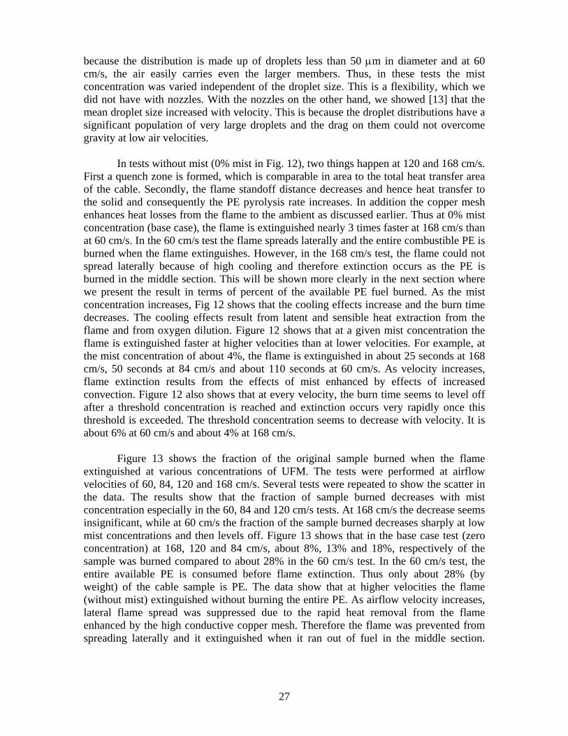
Figure 13 shows the fraction of the original sample burned when the flame
extinguished at various concentrations of UFM. The tests were performed at airflow velocities of 60, 84, 120 and 168 cm/s. Several tests were repeated to show the scatter in the data. The results show that the fraction of sample burned decreases with mist concentration especially in the 60, 84 and 120 cm/s tests. At 168 cm/s the decrease seems insignificant, while at 60 cm/s the fraction of the sample burned decreases sharply at low mist concentrations and then levels off. Figure 13 shows that in the base case test (zero concentration) at 168, 120 and 84 cm/s, about 8%, 13% and 18%, respectively of the sample was burned compared to about 28% in the 60 cm/s test. In the 60 cm/s test, the entire available PE is consumed before flame extinction. Thus only about 28% (by weight) of the cable sample is PE. The data show that at higher velocities the flame (without mist) extinguished without burning the entire PE. As airflow velocity increases, lateral flame spread was suppressed due to the rapid heat removal from the flame enhanced by the high conductive copper mesh. Therefore the flame was prevented from spreading laterally and it extinguished when it ran out of fuel in the middle section.

0
5
10
15
20
25
30
0 2 4 6 8 10 12 14 16 18
Mist mass loading
% o
f orig
inal
sam
ple
burn
ed
U=60 cm/sU= 84 cm/sU= 120 cm/sU= 168 cm/s
Figure 13: Fraction of the cable sample burned up to flame extinguishment versus mist mass fraction
28

29
In the 120 and 168 cm/s tests a quench zone was established on the upstream
surface of the cable. This leads to further cooling of the flame enhanced by the highly conductive copper mesh. Because of higher convective cooling the percentage of the sample burned with mist at 120 cm/s is higher than at 168 cm/s. In the 168 cm/s test in particular, the percentage of sample burned seem to remain constant but it took longer time (burn time) at higher mist concentrations to run out of fuel in the middle as Fig 12 shows. In the 60 and 84 cm/s tests, the flame was wrapped around the sample before mist came in. As mist was introduced, the cooling effects of mist led to the establishment of a quench zone on the upstream surface of the cable and the formation of a wake flame. At this stage one might expect that the 84 cm/s test would have a higher suppression in burning than the 60 cm/s test because of higher convective cooling. However, Fig. 13 shows the opposite. Furthermore, the flame standoff distance in the 84 cm/s test may be smaller than that in the 60 cm/s test and so the heat feedback rate might be higher in that test. This could lead to higher burning rate. There is need to further investigated the effects of concentration at low air velocities. 4.0 SUMMARY The results of experiments to study the burning characteristics of Navy communication cables with and without water mist in cross-flow have been presented. The cables were burned without the outer jacket to simulate the worst-case scenario. Ultra fine mist with sauter mean diameter of about 3 µm was generated using NanoMist System’s ultrasonic mist generator while high-pressure spray nozzles were used to generate mist with mean droplet diameters of about 20 µm. Suppression effectiveness was measured in terms extinguishment time and suppression in burnt mass fraction. The results are summarized as follows.
The UFM cools the flame rapidly turning the envelope flame into a wake flame, which shrinks in size and eventually extinguishes. At the current test conditions, extinguishment was by flame shrinking rather than flame blow-off. The UFM droplets follow the streamlines, which diverge as they come to the flame and our temperature measurements indicate that the fine droplets do not entered the wake flame.
A comparison of the results with PMMA rods and our earlier results with PMMA plates reveal that the effect of geometry is huge. A much larger concentration of UFM is required to extinguish a flame over a cylindrical rod than that over a flat plate.
The results also show that UFM extinguishes the flame faster than the larger spray nozzle mist at the same mist concentration measured at the fire location. It is suspected that the poor performance of spray nozzle mist may be due to the additional effects of spray-induced turbulence.
The results of tests with PMMA rods wrapped with the same copper wire mesh as was used in the cables, strongly suggest that the copper wire mesh played a significant role in the suppression effectiveness of the water mist. It seems that the

30
copper mesh enhanced mist effectiveness by facilitating rapid heat removal from the flame.
In tests with UFM, where we could vary concentration and velocity independent of the droplet size, our results show that the cable flame extinguishes rapidly after a threshold concentration is reached and that the threshold concentration is less at higher velocities.
5.0 ACKNOWLEDGEMENTS
We appreciate the contributions of Mr. Clarence Whitehurst in conducting the experiments and we thank Nanomist Systems LLC for providing the ultra fine mist generator. This work was funded by the office of Naval Research, through Naval Research Laboratory and Code 334, under the Damage Control Task of the FY03 Surface Ship Hull, Mechanical and Electrical Technology Program. Geo-Centers Inc. thanks the Navy Technology Center for Safety and Survivability for their support in this work 6.0 REFERENCES 1. Dobson, P.H., “FMRC cable fire Testing: Present / Future”, Pulp and paper Canada,
95, p129 – 131(1994) 2. McClung, L.B. and Ramachandran, S., “Improvement in fire safety features of
electrical conductors and cables”, IEEE Trans. on power delivery, 10 pp.43-52 (1991) 3. Coaker, A. W., Hirschler, M.M. and Shoemaker, C “Rate of heat release rate testing
for vinyl wire and cable materials with reduced flammability and smoke – Full scale cable tray tests and small-scale tests” Fire safety J 19 pp.19-53 (1992)
4. Leung C.H; Staggs J Brinley J McIntosh A and Whiteley R The effects of a inert
central core on the thermal pyrolysis of an electrical cable “ Fire Safety J. 43 (2000) p 143-168
5. Alexander J.E. et al “Navy electrical cable full-scale fire tests of 1985 at Mobile,
Alabama” Naval Research Laboratory Memorandum report NRL/MR/6180-89- 6395 Feb. 1989
6. Alexander J.E et al. “Complete enclosure large scale electrical cable fire tests” Naval
Research Laboratory Memorandum report NRL/MR/6183-93- 7327 May 26 1993 7. Toomey, T.A. and Williams, F.W., “Firefighting Tests for Electrical Cables”, NRL
Letter Report 3960, Ser 6180/932, Naval Research Laboratory, Washington DC, November 18, (1985)
8. Simpson T and Smith D. P “A fully integrated water mist fire suppression system for
telecommunication and other electronics cabinet” Water Mist instead of Halon? – International Conference on water mist fire suppression systems, Boras, Sweden Noember 4-5, 1993

9. Grant G Brenton J and Drysdale D. “ Fire suppression by water sprays” Progress in Energy and Combustion Science 26 (2000) p 79-130
10. Adiga, K. C. and Adiga, R,. “Method and device for production, extraction and
delivery of mist with ultra fine droplets,” U.S Patent Publication 20030127535 11. Forssell, E.W., Scheffey, J.L., DiNenno, P.J., Back, G.G., Adiga, K.C., Hatcher, Jr.,
R., Farley, J., and Williams, F.W., “False deck testing of NanoMist Water Mist Systems”, NRL Ltr Report 3905, Ser 6180/0228, Naval Research Laboratory, Washington DC, July 13, (2004)
12. Back GG, DiNenno P, Leonard J.T and Darwin R. L “Full-scale test of water mist fire
suppression systems for navy shipboard machinery space: phase I – unobstructed spaces” Naval Research Laboratory Memorandum report NRL/MR/6180-96- 7830 1996
13. Ndubizu C; Ananth R and Williams F.W., “Water mist Suppression of PMMA
boundary layer combustion - A Comparison of NanoMist and Spray nozzle performance.” Naval Research Laboratory Memorandum report NRL/MR/6180-04- 8824 Sept. 20 2004
14. Goldmeer, J., Tien, J.S., and Urban, D.L., “Combustion and extinction of PMMA
cylinders during depressurization in low-gravity” Fire Safety J., 32, 61 (1999) 15.Ndubizu, C.C; Ananth, R.; Tatem, P.A “Transient burning rate of a Non-charring plate
under a forced flow boundary layer flame” Combust. Flame 141 (2005) pp. 131-148 16. Ndubizu, C.C; Ananth, R.; Tatem, P.A, “The burning of a thermoplastic material
under a forced-flow boundary layer flame” Naval Research Laboratory Memorandum report NRL/MR/6180-02- 8630 July 31 2002
17. Ndubizu, C.C.,Ananth and Tatem P.A, “Burning rate distributions for boundary layer
flow combustion of a PMMA plate in forced flow” Combust. Flame 135 (2003) pp 35-55
18. Tsa, S.S., Liu, E.T. and Chen, C.H., “Numerical study for interaction between water
mist and counterblow diffusion flame over Tsuji burner” Comb. Sci. and Tech., 167, 257 (2001)
19. Ndubizu C.C, Ananth, R and Tatem P.A. “The effects of droplet size and injection
orientation on water mist suppression of low and high boiling point liquid pool fires” Combust. Sci. and Tech 157: 63-86 (2000)
20. Rasbash, D.J., Rogowski, Z.W. and Stark, G.W.V. “ Mechanism of extinction of
liquid fires with water sprays” Combustion and Flame, 4 :223 (1960) 21. S Takahashi “Extinguishment of plastic fire with plain water and wet water” Fire
Safety J. 22 pp 169-179 (1994)
31

APPENDIX I
Bare Power and control cables
after attempts to ignite them
Fresh power and control cables with and without armor
Figure A1: Pictures of power and control cables
A -1

APPENDIX II
b
a
c
Figure A2: Picture of Spray nozzles used in the tests – (a) Cold Fog nozzle; (b) WDB nozzle; (c) Arrangement of two cold fog nozzle for higher mist flow
A-2