Supporting adaptive routing in IBA switches
16
Supporting adaptive routing in IBA switches q J.C. Mart ınez * , J. Flich, A. Robles, P. L opez, J. Duato Department of Computer Engineering (DISCA), Universidad Polit ecnica de Valencia, Camino de Vera 14, 46071 Valencia, Spain Abstract InfiniBand is a new standard for communication between processing nodes and I/O devices as well as for inter- processor communication. The InfiniBand Architecture (IBA) supports distributed deterministic routing because for- warding tables store a single output port per destination ID. This prevents packets from using alternative paths when the requested output port is busy. Despite the fact that alternative paths could be selected at the source node to reach the same destination node, this is not effective enough to improve network performance. However, using adaptive routing could help to circumvent the congested areas in the network, leading to an increment in performance. In this paper, we propose a simple strategy to implement forwarding tables for IBA switches that supports adaptive routing while still maintaining compatibility with the IBA specs. Adaptive routing can be individually enabled or disabled for each packet at the source node. The proposed strategy enables the use in IBA of any adaptive routing algorithm with an acyclic channel dependence graph. In this paper, we have taken advantage of the partial adaptivity provided by the well-known up*/down* routing algorithm. Evaluation results show that extending IBA switch capa- bilities with adaptive routing may noticeably increase network performance. In particular, network throughput im- provement can be, on average, as high as 66%. Ó 2003 Elsevier B.V. All rights reserved. Keywords: System area networks; InfiniBand; Adaptive routing; Virtual addressing 1. Introduction More than 180 companies, including the leading computer manufactures, support the InfiniBand [5] initiative. The InfiniBand is an interconnect technology for processing and I/O nodes to form a system area network (SAN). The architecture is independent of the host operating system and processor platform. InfiniBand is designed to solve the lack of high bandwidth, concurrency and reli- ability of existing technologies for system area networks. InfiniBand supports a range of appli- cations from being the backplane interconnect of a single host, to a complex system area network consisting of multiple independent and clustered hosts and I/O components. The InfiniBand Architecture (IBA) is designed around a switch-based interconnect technology with high-speed serial point-to-point links con- necting processor nodes and I/O devices. An IBA q This work was supported by the Spanish Ministry of Science and Technology under Grants TIC2000-1151-C07, and by Generalitat Valenciana under Grant CTIDIB/2002/288 and by JJCC de Castilla-La Mancha under grant PBC-02-008. * Corresponding author. Tel.: +34-963-87-70-07; fax: +34- 963-87-75-79. E-mail address: [email protected] (J.C. Mart ınez). 1383-7621/$ - see front matter Ó 2003 Elsevier B.V. All rights reserved. doi:10.1016/S1383-7621(03)00103-6 Journal of Systems Architecture 49 (2003) 441–456 www.elsevier.com/locate/sysarc
-
Upload
jc-martinez -
Category
Documents
-
view
214 -
download
2
Transcript of Supporting adaptive routing in IBA switches

Journal of Systems Architecture 49 (2003) 441–456
www.elsevier.com/locate/sysarc
Supporting adaptive routing in IBA switches q
J.C. Mart�ıınez *, J. Flich, A. Robles, P. L�oopez, J. Duato
Department of Computer Engineering (DISCA), Universidad Polit�eecnica de Valencia, Camino de Vera 14, 46071 Valencia, Spain
Abstract
InfiniBand is a new standard for communication between processing nodes and I/O devices as well as for inter-
processor communication. The InfiniBand Architecture (IBA) supports distributed deterministic routing because for-
warding tables store a single output port per destination ID. This prevents packets from using alternative paths when
the requested output port is busy. Despite the fact that alternative paths could be selected at the source node to reach
the same destination node, this is not effective enough to improve network performance. However, using adaptive
routing could help to circumvent the congested areas in the network, leading to an increment in performance.
In this paper, we propose a simple strategy to implement forwarding tables for IBA switches that supports adaptive
routing while still maintaining compatibility with the IBA specs. Adaptive routing can be individually enabled or
disabled for each packet at the source node. The proposed strategy enables the use in IBA of any adaptive routing
algorithm with an acyclic channel dependence graph. In this paper, we have taken advantage of the partial adaptivity
provided by the well-known up*/down* routing algorithm. Evaluation results show that extending IBA switch capa-
bilities with adaptive routing may noticeably increase network performance. In particular, network throughput im-
provement can be, on average, as high as 66%.
� 2003 Elsevier B.V. All rights reserved.
Keywords: System area networks; InfiniBand; Adaptive routing; Virtual addressing
1. Introduction
More than 180 companies, including the leading
computer manufactures, support the InfiniBand
[5] initiative. The InfiniBand is an interconnect
technology for processing and I/O nodes to form a
qThis work was supported by the Spanish Ministry of
Science and Technology under Grants TIC2000-1151-C07, and
by Generalitat Valenciana under Grant CTIDIB/2002/288 and
by JJCC de Castilla-La Mancha under grant PBC-02-008.* Corresponding author. Tel.: +34-963-87-70-07; fax: +34-
963-87-75-79.
E-mail address: [email protected] (J.C. Mart�ıınez).
1383-7621/$ - see front matter � 2003 Elsevier B.V. All rights reserv
doi:10.1016/S1383-7621(03)00103-6
system area network (SAN). The architecture is
independent of the host operating system and
processor platform. InfiniBand is designed to solve
the lack of high bandwidth, concurrency and reli-
ability of existing technologies for system area
networks. InfiniBand supports a range of appli-
cations from being the backplane interconnect of asingle host, to a complex system area network
consisting of multiple independent and clustered
hosts and I/O components.
The InfiniBand Architecture (IBA) is designed
around a switch-based interconnect technology
with high-speed serial point-to-point links con-
necting processor nodes and I/O devices. An IBA
ed.

442 J.C. Mart�ıınez et al. / Journal of Systems Architecture 49 (2003) 441–456
network is divided into subnets interconnected by
routers, each subnet consisting of one or more
switches, processing nodes and I/O devices. IBA
supports any topology defined by the user.
Routing in IBA subnets is distributed, based on
forwarding tables stored in each switch which onlyconsider the packet destination ID for routing
packets [6]. IBA routing is deterministic since the
routing tables only store one output link per des-
tination ID. Although IBA switches support vir-
tual lanes, they cannot be selected dynamically at
each switch. Virtual lanes are mainly intended for
providing QoS to applications.
As shown in [2], the applied routing scheme hasa great influence on network performance. Deter-
ministic routing is used in many network inter-
connects due to its simplicity [1,9]. However,
deterministic routing algorithms do not make ef-
fective use of network links. Usually, a unique
path is provided for each source–destination pair.
If one or more channels of this path are busy, then
the traffic between that source–destination pairwill be delayed. This could be avoided by dy-
namically selecting an alternative path that does
not contain the busy ones.
IBA allows the use of alternative paths between
any source–destination paths. 1 The final path is
selected at each source node according to certain
criterion (random, round-robin, etc.). However, by
using alternative paths selected at the source node,the overall network performance is hardly im-
proved [3,4]. Notice that the source node does not
have information about the status of the channels
along the path. Indeed, channel status depends on
the current traffic pattern in the network, which is
not known by the network nodes. Therefore, se-
lecting alternative paths at the source node is not
enough to manage network congestion.Adaptive routing [2] dynamically builds the
path used by a packet, selecting the channels along
it taking into account network status information.
With adaptive routing, when a switch has to for-
ward a packet towards a particular destination, it
can choose the channel to use from a set of alter-
native channels. This selection can be done upon
1 By means of the virtual addressing scheme of IBA [6].
the status of the channels (busy or free) and
therefore, the busy channels are skipped. Hence,
adaptive routing allow packets to circumvent the
congested areas, thus making better use of net-
work resources and increasing network perfor-
mance. Indeed, several proposed adaptive routingalgorithms have demonstrated [2] their better
performance when compared to deterministic
routing algorithms.
However, adaptive routing has some draw-
backs. The first one is that it increases the switch
complexity. In particular, distributed routing (as
opposed to source routing) [2] and channel selec-
tion logic are required. The second one is the factthat it cannot guarantee in-order packet delivery.
However, in most current applications, there exists
a certain percentage of the traffic that may be de-
livered out-of-order (OOO). In these cases, it could
be worthwhile allowing packets to be adaptively
routed to improve network performance. More-
over, in-order packets could also benefit from
using adaptive routing if packets were reordered atthe destination host at the expense of imposing
certain overhead in packet delivery.
2. Motivation
InfiniBand specifications do not explicitly allow
adaptive routing. Effectively, IBA specs state thatforwarding tables must provide only one physical
output port per destination node. However, IBA
specs does not specify anything about how to im-
plement the forwarding tables in IBA switches.
Moreover, the IBA specs do not define the internal
architecture of a switch. On the other hand, IBA
switches already support distributed routing.
Thus, enhancing switch capabilities to supportadaptive routing could be feasible, with low in-
fluence on switch complexity.
In this paper, we take on such a challenge. We
propose a simple strategy to implement the for-
warding tables for IBA switches with the aim of
supporting adaptive routing while still maintaining
compatibility with the IBA specs. This could be
specially of interest for IBA switch manufacturersin order to improve the capabilities of the future
IBA switches.

J.C. Mart�ıınez et al. / Journal of Systems Architecture 49 (2003) 441–456 443
The rest of the paper is organized as follows. In
Section 3 the proposed mechanism is described. In
Section 4 the mechanism is evaluated with the up*/
down* routing algorithm, which provides partial
adaptivity when implemented in a distributed way.
Finally, in Section 5 some conclusions are drawn.
2 The linear forwarding table provides a simple map from
LID to output port. In other words, the table contains only
output ports and the LID acts as an index into the table.
3. Description of the proposed mechanism
In this section, we will present how IBA
switches can provide adaptivity while still main-
taining compatibility with the IBA specs.
An IBA network is composed by end nodes
interconnected by switches. Each end node con-
tains one or more channel adapters (CA). Each
channel adapter contains one or more ports. Each
port has a local identifier (LID) assigned by thelocal subnet manager, which is unique within the
subnet. IBA switches route packets based on for-
warding tables stored at each switch, addressed by
the packet destination local identifier (which is
referred to as the destination LID or DLID). As
this table only returns one output port to forward
the packet towards its destination, IBA switches
does not support adaptive routing. In order tosupport adaptivity, each switch should supply
several feasible output ports when a packet is
routed.
We can use a trick to support adaptive routing
in IBA switches. IBA allows a single destination to
be assigned not only a unique address but a range
of them by defining a LID Mask Control or LMC
[6]. The LMC specifies the number of least signif-icant bits of the LID that a physical port masks
(ignores) when it validates that a packet DLID
matches its assigned LID. As these bits are not
ignored by the switches, from the subnet point of
view, each CA port has been assigned a range of
consecutive addresses (up to 2LMC consecutive ad-
dresses). Each CA port will accept all packets
destined for any valid address within its range.The idea is to assign to each destination port the
same number of addresses as the number of de-
sired routing options at each switch. Assume that
we want two routing options per switch. This
consumes two addresses per destination port (for
instance, the addresses d and d þ 1 refers to the
same port D). As these addresses are different from
the subnet point of view, all network switches will
store the two routing options in the forwarding
tables, in the positions assigned to d and d þ 1.
When a packet destined to address d arrives at a
switch, it will access not only to address d in theforwarding tables but also to d þ 1, thus providing
two routing options to the packet. Once we have
two routing options for the packet, one of them
has to be finally selected. Several strategies can be
used to select the output port. We will refer to this
issue later.
In order to access to the two addresses of the
forwarding table, either both of them are accessedsequentially or a multiport memory is used. Both
options slow down routing, as the former requires
two table accesses and the latter may increase table
access time. However, if a linear forwarding table 2
[6] is used at switches, a simple implementation can
be done by organizing the forwarding table as an
interleaved memory composed by two modules
that are selected by the least significant bit. Theaddressing logic is designed in such a way that it
returns simultaneously the data found at addresses
d and d þ 1.
Although the two tables are internally accessed
in parallel for routing, the interleaved organization
makes the table to be externally viewed as a single
table. Therefore, we conform with IBA specifica-
tions. Forwarding tables are filled up by the subnetmanager at initialization time. The subnet man-
ager does not know anything about adaptivity at
switches. It assigns an output port to each table
address. Hence, to fully support the proposal we
made in this paper, once the different routing
choices have been computed for a given destina-
tion, the subnet manager stores them in a range of
addresses of the forwarding tables, as if they weredifferent destinations.
As we stated in Section 2, adaptive routing may
not be useful every time. In fact, some data
streams will have to be sent by using deterministic
routing in order to guarantee in-order delivery. In
444 J.C. Mart�ıınez et al. / Journal of Systems Architecture 49 (2003) 441–456
order to deal with these situations, we have pro-
vided a way of enabling/disabling the proposal
described in this paper. Sender nodes are respon-
sible of selecting an adaptive or deterministic path
for a given packet before injecting it into the net-
work. This is achieved by using different destina-tion addresses in the packet header. In fact, we
are already using several addresses per each host
to store the different available routing options. To
indicate that a given packet must be forwarded to
a given destination port D by using a deterministic
path, the first address assigned to the destination
(d) will be used in the packet header whereas if
adaptive routing is desired, the address (d þ 1) willbe used instead. Thus, by inspecting only one bit
(the least significant bit), the switch knows if only
one or all routing options must be provided. Of
course, to make this scheme work, the path to be
followed by packets sent using deterministic rout-
ing should be stored in the first address assigned to
each destination host.
This idea can be easily generalized to providemore than two routing options (say x). This re-
quires to reserve a range of x addresses for each
port and fill-up this range in the forwarding tables
with the correct output ports. Most important, the
forwarding table must be organized in such a way
that it returns the x output ports each time it is
accessed while maintaining a linear interface to the
subnet manager. If x is a power of two, this can beaccomplished again by arranging the forwarding
table as an interleaved memory.
Notice that IBA specifications allow for a
maximum of 128 different addresses per destina-
tion port. Thus, a maximum of 128 different
routing options could be provided with the pro-
posed scheme, which seems more than required. In
practice, as there are a little number of differentpaths to forward a packet to its destination from a
given switch, with a low number of routing options
is enough. See Section 4 for details. Hence, al-
though the proposed mechanism consumes some
virtual addresses but (i) the number of required
addresses is low and (ii) it is not a scarce resource.
Concerning the selection of the output port that
will be finally used, several alternatives can beapplied. We will assume that in the original switch
design, the forwarding table is accessed as soon as
a packet arrives at the switch, before reaching
the head of the queue. After routing the packet,
the returned output port is stored together with the
packet and when it gets the head of the queue,
arbitration for the output port is performed at the
internal switch level.When several output ports are returned by the
forwarding table, the selection can be done either
immediately or can be delayed until arbitration at
the internal switch is done. In both cases, the
choice can be done without considering the status
of the required output ports (for instance, ran-
domly selecting the output port) or considering it
(for instance, selecting the output port with morebuffer space). Although making the selection at
arbitration time may lead to better performance as
more updated status information can be used, it
requires to store all the routing options obtained
after accessing the forwarding tables until arbi-
tration is performed. On the contrary, making the
selection immediately after accessing the forward-
ing table is simpler, as it does not require tomodify the switch arbitration logic. In this case,
notice that output selection is performed according
to the output port status existing in that moment.
Finally, notice that a given system may have
both switches that support adaptive routing and
switches that only support deterministic routing.
There is no problem in combining both kinds of
switches in the same network. Obviously, only theadaptive switches will provide more than one
routing option. However, care must be taken to
store, in the deterministic switches, all the ad-
dresses that correspond to the same destination
port with the same switch output port, the only
available at that switch for that destination.
Fig. 1 shows the implementation of the mech-
anism when two routing options are provided ateach switch. The destination field of the packet
(the DLID) is used to access the forwarding table,
obtaining simultaneously two output ports. To
allow these two simultaneous accesses, the for-
warding table is organized in two interleaved
modules. In order to select the switch output port
that will be finally used, the least significant bit of
the DLID is first checked. If it is set to zero, de-terministic routing is required for the packet, so
the switch output port that corresponds to the first

02
1
3
dst
dst+1
dst+1
Forwarding table
dst
3210
output port
output port
Selectionlogic
LSB (dst)
output portsstatus
datadst
output port
output port
LSB (dst)
selectedoutput port
Fig. 1. Supporting adaptive routing in IBA switches.
J.C. Mart�ıınez et al. / Journal of Systems Architecture 49 (2003) 441–456 445
address is directly selected. In other case, which
corresponds to adaptive routing, the selection is
performed either immediately or at the internal
switch arbitration time, and either considering the
status of the output ports or performing a static
selection.
4. Performance evaluation
In this section we will evaluate the impact on
network performance of the proposed strategy.
For this purpose, we have developed a detailed
simulator that allows us to model the network at
the register transfer level following the IBA spec-ifications [6]. First, we will describe the IBA subnet
model defined in the specs together with the sim-
ulator parameters and the modeling considerations
we have used in all the evaluations. Then, we will
evaluate the adaptive technique proposed under
different topologies and different traffic patterns.
4.1. The IBA subnet model
The IBA specification defines a switch-based
network with point-to-point links, allowing any
topology defined by the user. The network allows
the communication between end-nodes. The end-
nodes are attached to switches using the same links
used between switches.
Packets are routed at each switch by accessingthe forwarding table. This table contains the out-
put port to be used at the switch for each possible
destination. Several routing options are provided
based on the strategy proposed in this paper. In
particular, the routing options will be computed
by using the DFS routing algorithm [7], which
improves the strategy used to compute the up*/
down* routing tables. This algorithm is partially
adaptive when implemented in a distributed way.The output port is selected at arbitration time and
considering the status of the requested output
ports, choosing randomly one of them that have
enough number of credits available.
Switches can support up to 16 virtual lanes
(VL). VLs can be used to form separate virtual
networks. We will use a non-multiplexed crossbar
on each switch. This crossbar supplies separateports for each VL. Buffers will be used both at the
input and the output side of the crossbar. Buffer
size will be fixed in both cases to 1 KB.
The routing time at each switch will be set to
100 ns. This time includes the time to access the
forwarding tables, the crossbar arbiter time, and
the time to set up the crossbar connections.
Links in InfiniBand are serial. In the simulator,the link injection rate will be fixed to the 1X con-
figuration [6]. 1X cables have a link speed of 2.5
Gbps. Therefore, a bit can be injected every 0.4 ns.
With 8/10 coding [6] a new byte can be injected
into the link every 4 ns.
We also model the fly time (time required by a
bit to reach the opposite link side). We will
model 20 m copper cables with a propagationdelay of 5 ns/m. Therefore, the fly time will be set
to 100 ns.

446 J.C. Mart�ıınez et al. / Journal of Systems Architecture 49 (2003) 441–456
The IBA specification defines a credit-based
flow control scheme for each virtual lane with in-
dependent buffer resources. A packet will be
transmitted over the link if there is enough buffer
space (credits of 64 bytes) to store the entire
packet. IBA allows the definition of different MTU(maximum transfer unit) values for packets rang-
ing from 256 to 4096 bytes. Additionally, the vir-
tual cut-through switching technique is used.
For each simulation run, we assume that the
packet generation rate is constant and the same for
all the end-nodes. Several packet destination dis-
tributions will be used: uniform, bit-reversal and
hot-spot. In the latter case, a hot-spot node israndomly selected and a percentage (5% and 15%)
of traffic is sent to this host. 32 and 256-byte
packets will be used.
In all the presented results, we will plot the
average packet latency 3 measured in nanoseconds
versus the average accepted traffic 4 measured in
bytes/ns/switch.
We will analyze irregular networks of 8, 16, and32 switches. These network topologies will be
randomly generated taking into account some re-
strictions. First, we will assume that every switch
in the network has the same number of ports (8
and 10-port switches will be used), using 4 or 6
ports to connect to other switches and leaving 4
ports to connect to nodes. And second, each
switches will be interconnected by exactly one link.Ten different topologies will be randomly gener-
ated for each network size. We will also show
minimum, maximum, and average results from
these topologies. Results plotted in this paper will
correspond to some representative topologies for
every network size.
4.2. Simulation results
In this section, we analyze the influence on net-
work performance of using IBA switches with
3 Latency is the elapsed time between the generation of a
packet at the source host until it is delivered at the destination
end-node.4 Accepted traffic is the amount of information delivered by
the network per time unit.
adaptive routing capabilities when applying up*/
down* routing. First, we study the advantages of
using IBA switches with adaptive routing capabil-
ities, also analyzing the influence of the percentage
of adaptive traffic on network performance. Then,
we analyze how the increments in the networkconnectivity and the adaptivity degree provided by
switches affect network performance. Finally, the
influence of combining VLs and adaptive routing is
analyzed.
4.2.1. Influence of the percentage of adaptive traffic
Fig. 2a, c and e show the simulation results for
the up*/down* routing algorithm when varying thepercentage of adaptive traffic from 0% (determin-
istic traffic) up to 100% for network sizes of 8, 16,
and 32 switches, respectively. Forwarding tables
provide two routing options at most, whereas the
switch connectivity consists of four links per switch.
Uniform packet destination distribution and 32-
byte packets are used. As it can be seen, the im-
provement on performance achieved by using IBAswitches with support for adaptive routing linearly
increases with the percentage of applied adaptive
traffic. However, in small network sizes, 75% of
adaptive traffic is enough to achieve practically
the maximum improvement in performance.
Throughput improvement with 100% adaptive
traffic ranges, on average, from a factor of 1.32
down to a factor of 1.23 for network sizes of 8 and32 switches, respectively. The lower throughput
increase observed for large networks with respect to
small networks is due to the low adaptivity degree
provided by the up*/down* routing algorithm.
Table 1 shows the number of routing options
computed for different network topologies. As can
be observed, the average percentage of routing de-
cisions where there is more than one routing optionavailable decreases as network size increases.
Table 2 shows the minimum, maximum, and
average factors of throughput increase corre-
sponding to ten network topologies for each net-
work size for 100% adaptive traffic and different
traffic patterns. These results confirm that small
networks take more advantage of using adaptive
routing.On the other hand, for hot-spot traffic, lower
improvements are achieved. The higher percentage

1000
1500
2000
2500
3000
3500
4000
4500
0.04 0.08 0.12 0.16 0.2
Ave
rage
Mes
sage
Lat
ency
(ns
)
Traffic (flits/ns/switch)
0%25%50%75%
100%
(a)
2000
3000
4000
5000
6000
7000
8000
0.05 0.1 0.15 0.2 0.25 0.3 0.35
Ave
rage
Mes
sage
Lat
ency
(ns
)
Traffic (flits/ns/switch)
0%25%50%75%
100%
(b)
100015002000250030003500400045005000
0.02 0.04 0.06 0.08 0.1
Ave
rage
Mes
sage
Lat
ency
(ns
)
Traffic (flits/ns/switch)
0%25%50%75%
100%
(c)
2000
3000
4000
5000
6000
7000
8000
0.04 0.08 0.12 0.16
Ave
rage
Mes
sage
Lat
ency
(ns
)
Traffic (flits/ns/switch)
0%25%50%75%
100%
(d)
1500
2000
2500
3000
0.01 0.02 0.03 0.04 0.05 0.06 0.07
Ave
rage
Mes
sage
Lat
ency
(ns
)
Traffic (flits/ns/switch)
0%25%50%75%
100%
(e)
2000250030003500400045005000550060006500
0.02 0.04 0.06 0.08 0.1 0.12
Ave
rage
Mes
sage
Lat
ency
(ns
)
Traffic (flits/ns/switch)
0%25%50%75%
100%
(f)
Fig. 2. Average packet latency vs. traffic with different percentages of adaptive traffic. 1 VL and 4 links connecting switches. Uniform
traffic pattern. Network size is (a, b) 8, (c, d) 16, and (e, f) 32 switches. Packet size is (a, c, e) 32 and (b, d, f) 256 bytes.
J.C. Mart�ıınez et al. / Journal of Systems Architecture 49 (2003) 441–456 447
sent to the hot-spot node, the lower improvement
achieved. This behavior is due to the fact that the
adaptivity degree exhibited by the up*/down*
routing algorithm is not enough to circumvent
appropriately those network areas where the trafficis concentrated.
For the bit-reversal traffic pattern, higher im-
provements are achieved. In Table 2, we can ob-
serve that the use of adaptive routing causes
throughput to increase, on average, by a factor of
1.43 for 8-switch networks and 32-byte packets
when using bit-reversal packet distribution. This is
because, unlike hot-spot traffic, congested areas
are spread through the network. This causes dif-
ferent traffic streams to interfere each other.However, using adaptive routing provides alter-
native paths for these traffic streams, helping to
reduce the overall network congestion. However,
for larger network sizes the factors in throughput
increase are similar to that obtained for uniform
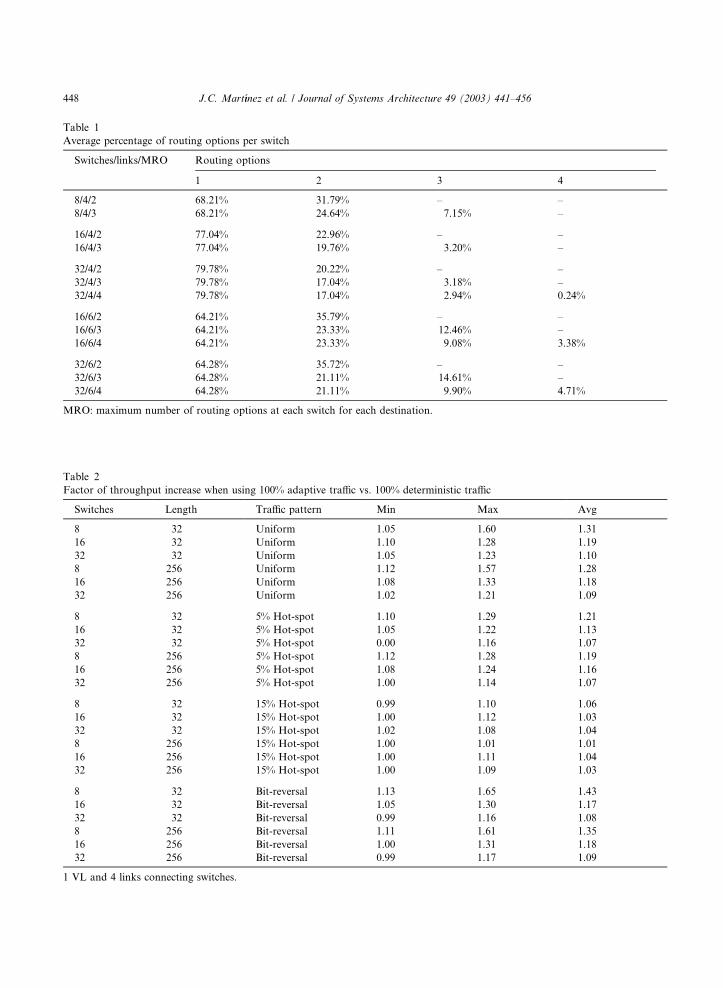
Table 1
Average percentage of routing options per switch
Switches/links/MRO Routing options
1 2 3 4
8/4/2 68.21% 31.79% – –
8/4/3 68.21% 24.64% 7.15% –
16/4/2 77.04% 22.96% – –
16/4/3 77.04% 19.76% 3.20% –
32/4/2 79.78% 20.22% – –
32/4/3 79.78% 17.04% 3.18% –
32/4/4 79.78% 17.04% 2.94% 0.24%
16/6/2 64.21% 35.79% – –
16/6/3 64.21% 23.33% 12.46% –
16/6/4 64.21% 23.33% 9.08% 3.38%
32/6/2 64.28% 35.72% – –
32/6/3 64.28% 21.11% 14.61% –
32/6/4 64.28% 21.11% 9.90% 4.71%
MRO: maximum number of routing options at each switch for each destination.
Table 2
Factor of throughput increase when using 100% adaptive traffic vs. 100% deterministic traffic
Switches Length Traffic pattern Min Max Avg
8 32 Uniform 1.05 1.60 1.31
16 32 Uniform 1.10 1.28 1.19
32 32 Uniform 1.05 1.23 1.10
8 256 Uniform 1.12 1.57 1.28
16 256 Uniform 1.08 1.33 1.18
32 256 Uniform 1.02 1.21 1.09
8 32 5% Hot-spot 1.10 1.29 1.21
16 32 5% Hot-spot 1.05 1.22 1.13
32 32 5% Hot-spot 0.00 1.16 1.07
8 256 5% Hot-spot 1.12 1.28 1.19
16 256 5% Hot-spot 1.08 1.24 1.16
32 256 5% Hot-spot 1.00 1.14 1.07
8 32 15% Hot-spot 0.99 1.10 1.06
16 32 15% Hot-spot 1.00 1.12 1.03
32 32 15% Hot-spot 1.02 1.08 1.04
8 256 15% Hot-spot 1.00 1.01 1.01
16 256 15% Hot-spot 1.00 1.11 1.04
32 256 15% Hot-spot 1.00 1.09 1.03
8 32 Bit-reversal 1.13 1.65 1.43
16 32 Bit-reversal 1.05 1.30 1.17
32 32 Bit-reversal 0.99 1.16 1.08
8 256 Bit-reversal 1.11 1.61 1.35
16 256 Bit-reversal 1.00 1.31 1.18
32 256 Bit-reversal 0.99 1.17 1.09
1 VL and 4 links connecting switches.
448 J.C. Mart�ıınez et al. / Journal of Systems Architecture 49 (2003) 441–456

J.C. Mart�ıınez et al. / Journal of Systems Architecture 49 (2003) 441–456 449
distribution due to the low adaptivity degree of
up*/down* routing.
Finally, in Fig. 2b, d and f and Table 2, we can
observe that packet length hardly has influence on
the performance improvement achieved by using
adaptive routing. In general, for long packetsfactor of throughput increase is similar to that
achieved by short packets.
4.2.2. Influence of increasing routing options and
network connectivity
Fig. 3a and c show the results for 16 and 32-
switch networks, respectively, when switches have
six ports to connect to other switches and for-warding tables provide up to three routing op-
tions. Uniform traffic and 32-byte packets are
used. In this case, the up*/down* routing will
provide more routing options. In Table 1 we can
observe that the percentage of routing decisions
with more than two options is higher.
1000
2000
3000
4000
5000
6000
0.05 0.1 0.15 0.2
Ave
rage
Mes
sage
Lat
ency
(ns
)
Traffic (flits/ns/switch)
0%100%
(a) (b
1000
1500
2000
2500
3000
0.04 0.08 0.12 0.16
Ave
rage
Mes
sage
Lat
ency
(ns
)
Traffic (flits/ns/switch)
0%100%
(c) (d
Fig. 3. Average packet latency vs. traffic. 1 VL and 6 links connecting
(c, d) 32 switches. Packet size is (a, c) 32 and (b, d) 256 bytes.
When using 100% adaptive traffic the through-
put increases by average factors of 1.38 and 1.33
for 16 and 32-switch networks, respectively. These
factors significantly improve those achieved by
using 4-port switches. The benefit of using adap-
tive routing increases as the number of routingoptions increases. The higher the network con-
nectivity, the greater the benefit of using adaptive
routing. With a connectivity of four links per
switch the maximum number of routing options
per switch would be theoretically four. However,
we have observed that it is not worth providing
more than two routing options per switch. This is
because the number of routing options supplied bythe routing algorithm is hardly greater than two
on average, as it is shown in Table 1. On the other
hand, the number of routing options significantly
increases with a connectivity of six links per
switch. In Table 3 we can observe that throughput
increase is noticeable when incrementing the
2000
3000
4000
5000
6000
7000
8000
9000
0.05 0.1 0.15 0.2 0.25 0.3 0.35
Ave
rage
Mes
sage
Lat
ency
(ns
)
Traffic (flits/ns/switch)
0%100%
)
2000250030003500400045005000550060006500
0.05 0.1 0.15 0.2 0.25
Ave
rage
Mes
sage
Lat
ency
(ns
)
Traffic (flits/ns/switch)
0%100%
)
switches. Uniform traffic pattern. Network size is (a, b) 16 and,

Table 3
Factor of throughput increase when using 100% adaptive traffic
vs. 100% deterministic traffic
Switches Msg.
length
MRO Min Max Avg
16 32-byte 2 1.27 1.30 1.29
32 32-byte 2 1.13 1.31 1.19
16 256-byte 2 1.22 1.29 1.26
32 256-byte 2 1.15 1.28 1.19
16 32-byte 3 1.33 1.65 1.44
32 32-byte 3 1.07 1.35 1.28
16 256-byte 3 1.29 1.51 1.38
32 256-byte 3 1.08 1.24 1.20
16 32-byte 4 1.32 1.74 1.46
32 32-byte 4 1.13 1.40 1.27
16 256-byte 4 1.31 1.65 1.40
32 256-byte 4 1.08 1.29 1.22
1 VL and 6 links connecting switches. Uniform traffic pattern.
MRO: maximum number of routing options at each switch for
each destination.
450 J.C. Mart�ıınez et al. / Journal of Systems Architecture 49 (2003) 441–456
number of routing options from two to three. In
particular, for 16-switch networks and two routing
options throughput increases, on average, by a
factor of 1.29, whereas with three routing options
the factor of throughput increase is 1.44. How-
ever, providing an additional routing optionhardly helps to increase the network throughput.
4.2.3. Influence of adaptive routing with virtual lanes
In [8] we have shown that only two VLs are
enough to reduce the head-of-line (HOL) blocking
effect in IBA networks, achieving practically the
same improvement in performance as that
achieved by the maximum number of VLs in IBA.In this section, we wonder if the use of adaptive
IBA switches can also help to increase network
performance when using two VLs for reducing the
HOL blocking effect.
As can be observed in Fig. 4, the benefits of
applying adaptive routing are more significant
when VLs are used. In particular, for 8-switch
networks and 256-byte packets the factor ofthroughput improvement increases from 1.25 up
to 1.39 when the number of VLs goes from one to
two. However, for large networks the performance
improvement is lower (from 1.20 up to 1.24). Table
4, which shows average results for ten topologies,
confirms these behavior.
4.2.4. Influence of IBA link bandwidth
Some manufacturers are currently offering IBA
HCAs and switches with 4X ports, which enable
point-to-point communication links between end
nodes with a higher bandwidth. Thus, we are also
interested in analyzing the influence on network
performance of enhancing the switch capabilitieswith adaptive routing support when using 4X
ports. Table 5 shows the minimum, maximum and
average factors of throughput increase corre-
sponding to ten network topologies for 16 and
32-switch networks. Two routing options are
provided for each DLID, and results are shown for
256-byte packets, 100% adaptive traffic and a
uniform distribution of message destinations. Fig.5 plots the simulation results for the network to-
pologies that exhibit an average behavior for each
network size. For comparison purposes, results for
1X ports are also included. We can observe that
the benefits of using 4X-port switches with adap-
tive routing support are equal to or slightly greater
than that achieved when using 1X ports. In par-
ticular, throughput is increased by 18% and la-tency is decreased for the full range of traffic.
There are also some commercial IBA products
(HCAs and switches) providing 4X ports that
allow each of these ports to be configured either as
a single 4X port or as four 1X ports, according
to the customer requirements. This is a way to
increase network connectivity (if needed) at the
expense of reducing the connection bandwidth,which will negatively affect the packet latency.
However, increasing connectivity could also im-
prove fault tolerance capabilities of the network by
including redundant links. Additionally, increas-
ing connectivity could also contribute to increase
the number of routing options. For this reason, we
are interested in analyzing if this new network
scenario allow us to take additional advantages ofsupporting adaptive routing in IBA switches.
In particular, we will analyze the behavior of a
network composed of 4X links and switches with
another network with the same topology but rec-
onfiguring switches to supply 1X ports and re-
placing each original 4X link by four 1X links (see

1000
2000
3000
4000
5000
6000
0.05 0.1 0.15 0.2 0.25 0.3
Ave
rage
Mes
sage
Lat
ency
(ns
)
Traffic (flits/ns/switch)
2VL 0%2VL 100%
1VL 0%1VL 100%
(a)
2000
4000
6000
8000
10000
12000
14000
16000
0.1 0.2 0.3 0.4 0.5
Ave
rage
Mes
sage
Lat
ency
(ns
)
Traffic (flits/ns/switch)
2VL 0%2VL 100%
1VL 0%1VL 100%
(b)
1000
2000
3000
4000
5000
6000
0.04 0.08 0.12 0.16
Ave
rage
Mes
sage
Lat
ency
(ns
)
Traffic (flits/ns/switch)
2VL 0%2VL 100%
1VL 0%1VL 100%
(c)
2000
4000
6000
8000
10000
12000
14000
16000
0.05 0.1 0.15 0.2 0.25
Ave
rage
Mes
sage
Lat
ency
(ns
)
Traffic (flits/ns/switch)
2VL 0%2VL 100%
1VL 0%1VL 100%
(d)
1500
2000
2500
3000
3500
4000
4500
0.02 0.04 0.06 0.08 0.1
Ave
rage
Mes
sage
Lat
ency
(ns
)
Traffic (flits/ns/switch)
2VL 0%2VL 100%
1VL 0%1VL 100%
(e)
250030003500400045005000550060006500
0.04 0.08 0.12 0.16
Ave
rage
Mes
sage
Lat
ency
(ns
)
Traffic (flits/ns/switch)
2VL 0%2VL 100%
1VL 0%1VL 100%
(f)
Fig. 4. Average packet latency vs. traffic with different percentages of adaptive traffic. 2 VLs and 4 links connecting switches. Uniform
traffic pattern. Network size is (a, b) 8, (c, d) 16, and (e, f) 32 switches. Packet size is (a, c, e) 32 and (b, d, f) 256 bytes.
J.C. Mart�ıınez et al. / Journal of Systems Architecture 49 (2003) 441–456 451
Fig. 6). We will refer to the original 4X links as
�links�, and to the 1X links as �sublinks� of these
ones. Indeed, If we have four sublinks per each
link, we can use them to balance network traffic
even when applying a deterministic routing. At
path computation time, paths traversing each of
original links are evenly distributed among the
sublinks it is split into. Table 6 shows the mini-mum, maximum and average factors of through-
put increase corresponding to ten network
topologies for 16 and 32-switch networks. Fig. 7
plots the simulation results for a network topology
that exhibit an average behavior. As we can see,
network performance is degraded when using four
1X links instead of one 4X link. Indeed, the net-
work with 4X links is faster than the network with
1X links not only when adaptive routing is used inthe 4X-link network but also without it. Therefore,

Table 5
Factor of throughput increase when using 100% adaptive traffic
(MRO ¼ 2) vs. 100% deterministic traffic with 4X links
Switches Link
bandwidth
Min Max Avg
16 1X 1.08 1.33 1.18
32 1X 1.02 1.21 1.09
16 4X 1.11 1.28 1.18
32 4X 1.09 1.26 1.17
256-byte packets. Uniform traffic pattern.
4X link 4 x 1X links
Fig. 6. Splitting each 4X link into four 1X links.
Table 6
Factor of throughput increase when using four 1X links with
deterministic routing vs. one 4X link with deterministic and
adaptive routing
Switches 4*1X links,
deterministic
4*1X links, adaptive
Min Max Avg Min Max Avg
16 0.78 0.97 0.88 0.67 0.81 0.73
32 0.95 1.11 1.00 0.79 0.95 0.86
256-byte packets. Uniform traffic pattern.
Table 4
Factor of throughput increase when using 100% adaptive traffic
vs. 100% deterministic traffic
Switches Msg.
length
Min Max Avg
8 32-byte 1.00 1.46 1.26
16 32-byte 1.07 1.40 1.22
32 32-byte 1.05 1.22 1.16
8 256-byte 1.03 1.59 1.32
16 256-byte 1.08 1.36 1.18
32 256-byte 1.00 1.25 1.13
2 VLs and 4 links connecting switches. Uniform traffic pattern.
452 J.C. Mart�ıınez et al. / Journal of Systems Architecture 49 (2003) 441–456
in this case, replacing high speed 4X links by four1X links is not interesting.
However, switches may allow the use of adap-
tive routing both with 4X links and 1X links. Next,
we will analyze this situation. Up to two routing
options will be offered in both cases. In the case of
the network with 1X links, in order to better bal-
ance traffic, the two routing options will be se-
lected from links connected to different switches
500
1000
1500
2000
2500
3000
3500
4000
0.08 0.16 0.24 0.32 0.4 0.48
Ave
rage
Mes
sage
Lat
ency
(ns
)
Traffic (flits/ns/switch)
1X(Det)1X(Adap)
4X(Det)4X(Adap)
(a) (
Fig. 5. Average packet latency vs. traffic when using 100% adaptive
256-byte packets. Uniform traffic pattern. Network size is (a) 16 swit
and from different sublinks, if available (see Fig.8(a)). Additionally, we have evaluated networks
where each original 4X link has been replaced by
two and three 1X links. This allows us to use the
remaining switch ports to increase the connectivity
by modifying the original network topology.
However, in order to make a fair comparison, in
the shown results, we have not taken advantage of
the increased connectivity, leaving the ports cor-responding to these sublinks unused. Table 7
shows the minimum, maximum and average fac-
10001500200025003000350040004500
0.04 0.08 0.12 0.16 0.2 0.24 0.28
Ave
rage
Mes
sage
Lat
ency
(ns
)
Traffic (flits/ns/switch)
1X(Det)1X(Adap)
4X(Det)4X(Adap)
b)
traffic (MRO ¼ 2) vs. 100% deterministic traffic with 4X links.
ches and (b) 32 switches.

2 routing options
(a)
4 routing options
(b)
8 routing options
(c)
Fig. 8. Selection of routing options.
Table 7
Factor of throughput increase when using several 1X links vs.
one 4X link with adaptive routing
Switches NOL Min Max Avg
16 2 0.65 0.70 0.67
16 3 1.05 1.12 1.09
16 4 1.20 1.39 1.29
32 2 0.68 0.73 0.70
32 3 1.12 1.25 1.18
32 4 1.44 1.61 1.53
MRO ¼ 2, 256-byte packets. Uniform traffic pattern. NOL:
number of 1X Links replacing each original 4X link; MRO:
maximum number of routing options at each switch for each
destination.
100015002000250030003500400045005000
0.04 0.08 0.12 0.16 0.2 0.24 0.28
Ave
rage
Mes
sage
Lat
ency
(ns
)
Traffic (flits/ns/switch)
4X(Det)4X(Adap)
4*1X(Det)
(a)
1000
2000
3000
4000
5000
6000
0.04 0.08 0.12 0.16 0.2 0.24 0.28
Ave
rage
Mes
sage
Lat
ency
(ns
)
Traffic (flits/ns/switch)
4X(Det)4X(Adap)
4*1X(Det)
(b)
Fig. 7. Average packet latency vs. traffic when using deterministic routing with four 1X links vs. one 4X link. 256-byte packets.
Uniform traffic pattern. Network size is (a) 16 switches and (b) 32 switches.
J.C. Mart�ıınez et al. / Journal of Systems Architecture 49 (2003) 441–456 453
tors of throughput increase corresponding to tennetwork topologies for 16 and 32-switch networks.
Fig. 9 plots the simulation results for a network
topology that exhibit an average behavior. As we
can see, the use of adaptive routing helps in im-
proving the performance of the network with 1X
links. In particular, by replacing each link by only
three sublinks, network throughput can be in-
creased, on average, by 10% and 18% for 16-switch
and 32-switch networks, respectively. If four sub-
links per link are used, factors of throughput in-
crease of 1.29 and 1.53 are achieved, respectively.As shown in Table 1, the up*/down* routing
algorithm is able to provide more than two routing
options only in a low number of cases. Hence,
when using only one link to connect neighbor
switches, it is not worth providing more than two
routing options. However, when there are several
sublinks connecting neighbor switches, we can
take advantage of using more routing options. Inparticular, this number is increased by a factor
equal to the number of sublinks connecting
neighbor switches. We will analyze different sce-
narios. First, we consider only the routing options
provided by the 1X links replacing the original 4X
link. Therefore, the number of routing options is
equal to the number of sublinks replacing each
link (see Fig. 8(b)). On the other hand, we willanalyze the case where we provide all the available
routing options, both the original ones (up to two)
provided by the 4X links and the new ones pro-
vided by splitting each link into several sublinks
(see Fig. 8(c)). Therefore, if each 4X link has been
split into n 1X links, the latter strategy will provide
up to 2n routing options, whereas the former will
provide only n routing options. Taken into ac-count that up*/down* routing supplies only one
routing option in most cases, the first strategy
seems more cost-effective because the n routing
options are always guaranteed. In particular, we

1000
2000
3000
4000
5000
6000
7000
8000
0.08 0.16 0.24 0.32 0.4 0.48 0.56
Ave
rage
Mes
sage
Lat
ency
(ns
)
Traffic (flits/ns/switch)
4X(Adap)3*1X(2op)4*1X(2op)
(a)
1000
2000
3000
4000
5000
6000
0.08 0.16 0.24 0.32 0.4 0.48
Ave
rage
Mes
sage
Lat
ency
(ns
)
Traffic (flits/ns/switch)
4X(Adap)3*1X(2op)4*1X(2op)
(b)
Fig. 9. Average packet latency vs. traffic when using several 1X links vs. one 4X link with adaptive routing. MRO ¼ 2, 256-byte
packets. Uniform traffic pattern. Network size is (a) 16 switches and (b) 32 switches.
454 J.C. Mart�ıınez et al. / Journal of Systems Architecture 49 (2003) 441–456
have evaluated the cases of three and four sublinks
replacing each link, which leads to 3 (6) and 4 (8)
routing options in the first (second) scenario.
Table 8 shows the minimum, maximum and av-
erage factors of throughput increase correspond-
ing to ten network topologies for 16 and 32-switchnetworks. Fig. 10 plots the simulation results for a
network topology that exhibit an average behav-
ior. As we can see, replacing each original link by
three sublinks with three routing options leads to
roughly the same network throughput for 16-swith
networks, whereas throughput is improved by 13%
for 32-switch networks. By doubling the maximum
number of routing options, network throughput isimproved by 12% and 23% for 16 and 32-switch
networks, respectively. If we split each original
link into four sublinks, network throughput is
significantly increased, specially for large net-
works. In particular, factors of throughput in-
1000
2000
3000
4000
5000
6000
7000
0.08 0.16 0.24 0.32 0.4 0.48 0.56
Ave
rage
Mes
sage
Lat
ency
(ns
)
Traffic (flits/ns/switch)
4X(Adap)3*1X(3op)3*1X(6op)4*1X(4op)4*1X(8op)
(a) (b
Fig. 10. Average packet latency vs. traffic when using several 1X links
byte packets. Uniform traffic pattern. Network size is (a) 16 switches
crease of 1.51 and 1.66 are obtained for 32-switch
networks when using four and eight maximum
routing options, respectively. However, if we com-
pare these results with the ones shown in Table 7,
we can see that for up*/down* routing it is not
worth providing support for more than two rout-ing options in IBA switches, because the obtained
improvement is negligible (1.34 vs. 1.29 for 16-
switch networks and 1.66 vs. 1.53 for 32-switch
networks). The two available routing options com-
bined with the better traffic balance obtained by
the use of four sublinks per link allows to achieve
almost the same throughput obtained by using the
maximum number of routing options.As can be seen, the larger the network size, the
greater the benefits of using several 1X links in
parallel with respect to using only one 4X link.
This is because in the latter case, the up*/down*
routing scheme provides a very small number of
1000
2000
3000
4000
5000
6000
0.08 0.16 0.24 0.32 0.4 0.48
Ave
rage
Mes
sage
Lat
ency
(ns
)
Traffic (flits/ns/switch)
4X(Adap)3*1X(3op)3*1X(6op)4*1X(4op)4*1X(8op)
)
vs. one 4X link with adaptive routing for different MROs. 256-
and (b) 32 switches.

Table 8
Factor of throughput increase when using several 1X links vs. one 4X link with adaptive routing for different MROs
Switches NOL MRO Min Max Avg
16 3 3 0.90 1.08 1.02
16 3 6 1.06 1.18 1.12
16 4 4 1.13 1.39 1.26
16 4 8 1.24 1.47 1.34
32 3 3 1.00 1.19 1.13
32 3 6 1.17 1.34 1.23
32 4 4 1.37 1.57 1.51
32 4 8 1.58 1.77 1.66
256-byte packets. Uniform traffic pattern. NOL: number of 1X links replacing each original 4X link; MRO: maximum number of
routing options at each switch for each destination.
J.C. Mart�ıınez et al. / Journal of Systems Architecture 49 (2003) 441–456 455
routing options (up to two). However, by using nsublinks per link, the number of routing options
available at each switch is multiplied by n. The
additional routing freedom can be exploited eitherby selecting one of them at routing time (as in the
results shown in Table 8) or by selecting two
routing options while balancing paths among the
available sublinks at forwarding table computing
time (as in the results shown in Table 7).
On the other hand, we can observe a significant
increase of latency for low and medium traffic
rates when using 1X links. In particular, latencyoverhead can be as high as 100%. This is an ex-
pected result, because packet latency is increased
proportionally to the reduction in the bandwidth
links. However, this is the price we have to pay to
achieve higher throughput values when increasing
connectivity between neighbor switches by split-
ting 4X links into several 1X links. This could be
the case when we try to improve fault toleranceswitch fabric capabilities by using redundant links,
without significantly increasing the network cost.
5. Conclusions
In this paper, we have proposed a simple
mechanism to enhance IBA switch capabilities tosupport adaptive routing while maintaining com-
patibility with IBA specs. Forwarding tables are
arranged in such a way that they can provide
several routing options at the same time. An in-
terleaved memory organization is used to imple-
ment linear forwarding tables at each switch while
allowing simultaneous accesses to them. In order
to select the output port, several selection policies
can be applied. Additionally, adaptive routing can
be enabled or disabled on a per-packet basis by therunning application.
The proposed mechanism has been evaluated
using the partially adaptive up*/down* routing
scheme. Results show that enhancing IBA switch
capabilities with adaptive routing noticeably in-
creases network performance. This is especially
significant for small networks. In particular, net-
work throughput improvement can be, on average,as high as 66%. In detail, we have obtained the
following results:
• Network performance roughly increases linearly
as the percentage of adaptive traffic increases.
• The advantage of using adaptive routing de-
creases as network size increases due to the
low adaptivity degree provided by the up*/down* routing algorithm.
• The advantage of using adaptive routing in-
creases as the network connectivity and the
routing options provided by the switches in-
crease.
• Adaptive routing benefits are neither compro-
mised when using two virtual lanes nor when in-
creasing link bandwidth (from 1X to 4X links).• In switches whose ports can be configured either
as one 4X port or four 1X ports, using adaptive
routing allows network throughput to be im-
proved by splitting each 4X link into four 1X
links at the expense of increasing network la-
tency for low and medium traffic rates.

456 J.C. Mart�ıınez et al. / Journal of Systems Architecture 49 (2003) 441–456
References
[1] N.J. Boden, D. Cohen, R.E. Felderman, A.E. Kulawik, C.L.
Seitz, J. Seizovic, W. Su, Myrinet––A gigabit per second
local area network, IEEE Micro (February 1995) 29–36.
[2] J. Duato, S. Yalamanchili, L.M. Ni, Interconnection Net-
works: An Engineering Approach, IEEE Computer Society
Press, Silver Spring, MD, 1997.
[3] J. Flich, M.P. Malumbres, P. Lopez, J. Duato, Improving
routing performance in Myrinet networks, in: Proceedings
of the International Parallel and Distributed Processing
Symposium, May 2000.
[4] J. Flich, Improving performance of networks of worksta-
tions with source routing, Ph.D. Thesis, March 2001.
[5] InfiniBandSM Trade Association. http://www.infini-
bandta.com.
[6] InfiniBandSM Trade Association, InfiniBandTMArchitecture.
Specification Volume 1. Release 1.0. Available at http://
www.infinibandta.com.
[7] J.C. Sancho, A. Robles, Improving the up*/down* routing
scheme for networks of workstations, in Proceedings of the
Euro-Par 2000, August 2000.
[8] J.C. Sancho, J. Flich, A. Robles, P. L�oopez, J. Duato,
Analyzing the influence of virtual lanes on InfiniBand
networks, in: Proceedings of the Communication Architec-
ture for Clusters Workshop 2002, April 2002.
[9] M.D. Schroeder et al., Autonet: A high-speed, self-config-
uring local area network using point-to-point links, Tech-
nical Report SRC research report 59, DEC, April 1990.
Juan Carlos Martınez received his MSin Computer Science from the Tech-nical University of Valencia (Univers-idad Polit�eecnica de Valencia), Spain, in1998. He joined the Department ofComputer Engineering (DISCA),Universidad Polit�eecnica de Valencia in1999, where he is currently a lecturerof Computer Arquitecture and Tech-nology. His current research interestsinclude multiprocessor systems, net-work of workstations, interconnectionnetworks, and cluster computing.
Jose Flich received his MS and PhDdegrees in Computer Science from theTechnical University of Valencia(Universidad Politecnica de Valencia),Spain, in 1994 and 2001, respectively.He joined the Department of Com-puter Engineering (DISCA), Universi-dad Polit�eecnica de Valencia in 1998where he is currently an AssociateProfessor of Computer Architectureand Technology. His research interestsare related to high performance in-terconnection networks for multi-processor systems and cluster ofworkstations.
Antonio Robles received an MS inphysics (electricity and electronics)from the University of Valencia, Spainin 1984 and a PhD in computer engi-neering from the Technical Universityof Valencia in 1995. He is currently anassociated professor on a permanentbasis in the Department of Informa-tion Systems and Computer Architec-ture at the Technical University ofValencia. His current research interestsinclude multiprocessor systems, net-work of workstations, interconnectionnetworks, fault tolerance, and clustercomputing.
Pedro Lopez received the BEng degreein electrical engineering and the MSand PhD degrees in computer engi-neering from the Technical Universityof Valencia (Universidad Politecnica deValencia), Spain, in 1984, 1990 and1995, respectively. He joined the De-partment of Computer Engineering(DISCA), Universidad Polit�eecnica deValencia in 1986, where he is currentlya Professor of Computer Architectureand Technology. He has taught severalcourses on computer organization andcomputer architecture. His research
interests include high performance interconnection networks formultiprocessor systems and cluster of workstations. Prof. L�oopez
is amember of the editorial board of Parallel Computing journal.Jose Duato received the MS and PhDdegrees in electrical engineering fromthe Technical University of Valencia,Spain, in 1981 and 1985, respectively.In 1981 he joined the Department ofSystems Engineering, Computers andAutomation at the Technical Univer-sity of Valencia. Currently, Dr. Duatois Professor in the Department ofComputer Engineering (DISCA). Hewas also an adjunct professor in theDepartment of Computer and Infor-mation Science, The Ohio State Uni-versity. His current research interests
include interconnection networks, multiprocessor architectures,networks of workstations, and switch fabrics for IP routers.
Prof. Duato has published over 230 refereed papers. He pro-posed a theory of deadlock-free adaptive routing that has beenused in the design of the routing algorithms for the MIT Re-liable Router, the Cray T3E supercomputer, the internal routerof the Alpha 21364 microprocessor, and the BlueGene/L su-percomputer. Prof. Duato is the first author of the book In-terconnection Networks: An Engineering Approach. This bookis currently the reference book on interconnection networks.Dr. Duato served as a member of the editorial boards of IEEETransactions on Parallel and Distributed Systems and IEEETransactions on Computers. He has been the General Co-Chairfor the 2001 International Conference on Parallel Processingand is the Program Committee Chair for the Tenth Interna-tional Symposium on High Performance Computer Architec-ture (HPCA-10). Also, he served as Co-Chair, member of theSteering Committee, Vice-Chair, or member of the ProgramCommittee in more than 30 conferences, including the mostprestigious conferences in his area (HPCA, ISCA, IPPS/SPDP,ICPP, ICDCS, Europar, HiPC).