Supply Secondary Air Unit SSAU - ECE UK
10
Selection Data Supply Secondary Air Unit SSAU
Transcript of Supply Secondary Air Unit SSAU - ECE UK
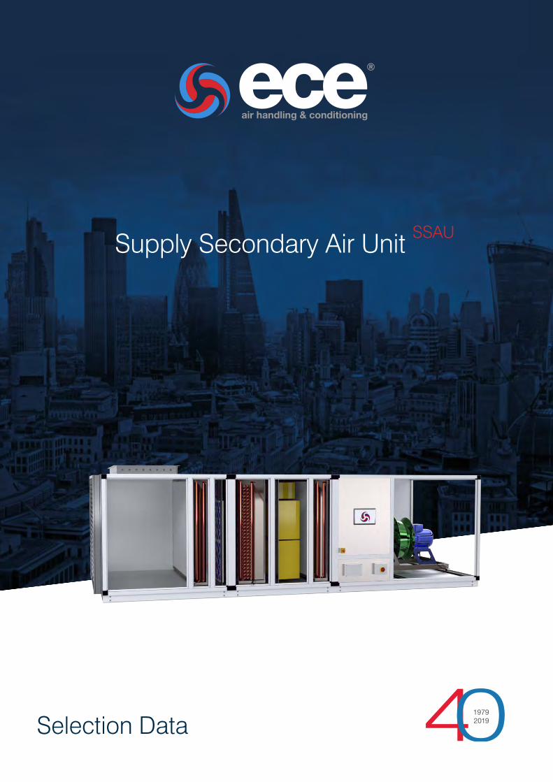
Selection Data
Supply Secondary Air Unit SSAU
Selection D
ataS
upply Secondary A
ir Unit S
SA
U
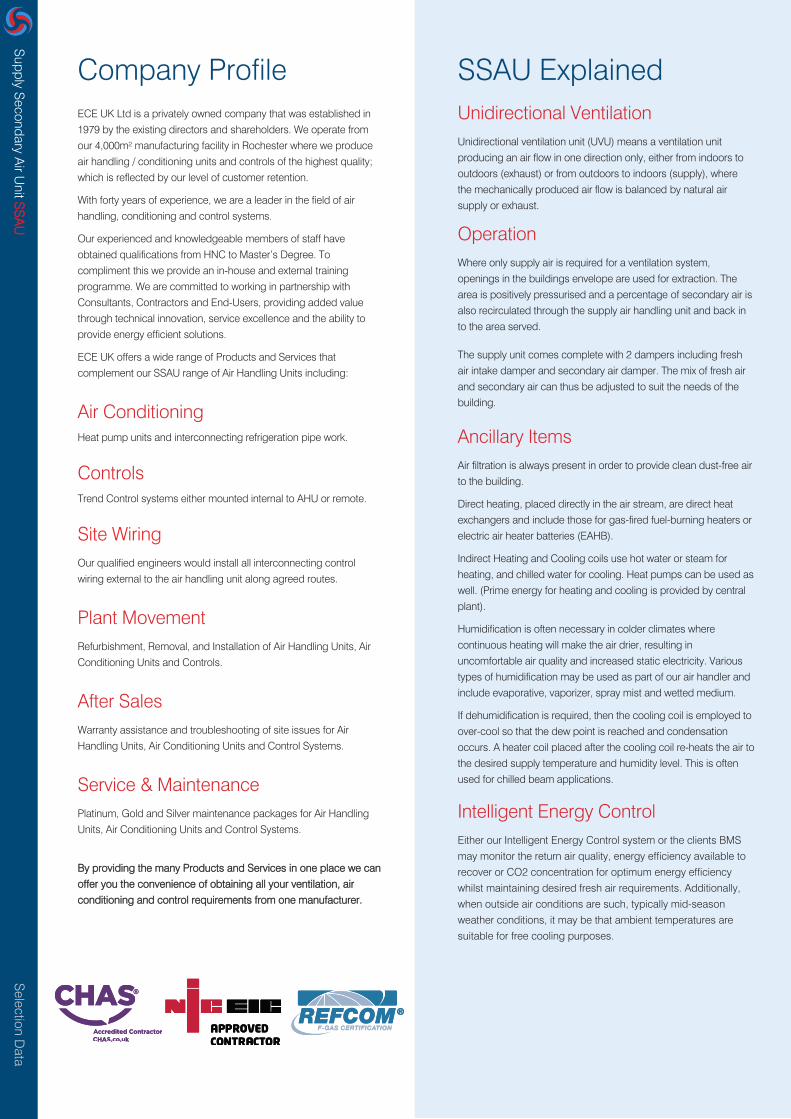
Company ProfileECE UK Ltd is a privately owned company that was established in
1979 by the existing directors and shareholders. We operate from
our 4,000m² manufacturing facility in Rochester where we produce
air handling / conditioning units and controls of the highest quality;
which is reflected by our level of customer retention.
With forty years of experience, we are a leader in the field of air
handling, conditioning and control systems.
Our experienced and knowledgeable members of staff have
obtained qualifications from HNC to Master’s Degree. To
compliment this we provide an in-house and external training
programme. We are committed to working in partnership with
Consultants, Contractors and End-Users, providing added value
through technical innovation, service excellence and the ability to
provide energy efficient solutions.
ECE UK offers a wide range of Products and Services that
complement our SSAU range of Air Handling Units including:
Air ConditioningHeat pump units and interconnecting refrigeration pipe work.
ControlsTrend Control systems either mounted internal to AHU or remote.
Site WiringOur qualified engineers would install all interconnecting control
wiring external to the air handling unit along agreed routes.
Plant MovementRefurbishment, Removal, and Installation of Air Handling Units, Air
Conditioning Units and Controls.
After Sales Warranty assistance and troubleshooting of site issues for Air
Handling Units, Air Conditioning Units and Control Systems.
Service & Maintenance Platinum, Gold and Silver maintenance packages for Air Handling
Units, Air Conditioning Units and Control Systems.
By providing the many Products and Services in one place we can
offer you the convenience of obtaining all your ventilation, air
conditioning and control requirements from one manufacturer.
SSAU Explained Unidirectional VentilationUnidirectional ventilation unit (UVU) means a ventilation unit
producing an air flow in one direction only, either from indoors to
outdoors (exhaust) or from outdoors to indoors (supply), where
the mechanically produced air flow is balanced by natural air
supply or exhaust.
OperationWhere only supply air is required for a ventilation system,
openings in the buildings envelope are used for extraction. The
area is positively pressurised and a percentage of secondary air is
also recirculated through the supply air handling unit and back in
to the area served.
The supply unit comes complete with 2 dampers including fresh
air intake damper and secondary air damper. The mix of fresh air
and secondary air can thus be adjusted to suit the needs of the
building.
Ancillary ItemsAir filtration is always present in order to provide clean dust-free air
to the building.
Direct heating, placed directly in the air stream, are direct heat
exchangers and include those for gas-fired fuel-burning heaters or
electric air heater batteries (EAHB).
Indirect Heating and Cooling coils use hot water or steam for
heating, and chilled water for cooling. Heat pumps can be used as
well. (Prime energy for heating and cooling is provided by central
plant).
Humidification is often necessary in colder climates where
continuous heating will make the air drier, resulting in
uncomfortable air quality and increased static electricity. Various
types of humidification may be used as part of our air handler and
include evaporative, vaporizer, spray mist and wetted medium.
If dehumidification is required, then the cooling coil is employed to
over-cool so that the dew point is reached and condensation
occurs. A heater coil placed after the cooling coil re-heats the air to
the desired supply temperature and humidity level. This is often
used for chilled beam applications.
Intelligent Energy ControlEither our Intelligent Energy Control system or the clients BMS
may monitor the return air quality, energy efficiency available to
recover or CO2 concentration for optimum energy efficiency
whilst maintaining desired fresh air requirements. Additionally,
when outside air conditions are such, typically mid-season
weather conditions, it may be that ambient temperatures are
suitable for free cooling purposes.

Selection D
ataS
upply Secondary A
ir Unit S
SA
U
Selection Information
• Dimensions on page 6 are for roughing in only.
• To keep specific fan power (SFP) within ERP 2016 and L2
requirements, the following should be adhered too:
- For AHU’s with external system resistance <200Pa for supply systems, keep the face velocity between 2.5 and 3.0 m/s.
For AHU’s with external system resistance between 200Pa –400Pa for supply systems, keep the face velocity between 2.0 and 2.5 m/s and include 635mm long bag filters.
• Contact technical sales for specials if unit sizes are difficult toaccommodate.
• Fan total pressures from 100Pa to 1500Pa (including AHUinternal losses).
• Maximum external pressure available i.e. AHU inlet negative pressures plus AHU discharge positive pressure = fan static pressure less AHU internal component resistances for bothextract and supply AHU’s.
• Height and width dimensions in tables are the AHU frameoutside dimensions. Add base dimension, also add roofdimension (RH) if unit is external.
• Component length dimensions are space that each internal component occupies.
• Maximum overall AHU length unlimited. (Maximum single piece size subject to transport restrictions).
• Frame inlet connections generally 30mm up to size 5 and 50mm size 6 and above, around frame perimeter, undrilled.
• Inlet connections can be mezz flanges 30mm and 40mm asrequired.
• Outlet fan connections from unit – see dimension tables.
• Individual section lengths including components like coils, attenuators or filters can range from 300mm to 2400mm. Each individual component does not have to sit within its ownsection.
• It is possible to have up to 4 stages of filtration.
• “X” dimension will only be required if the supply fan isdownstream of a full face component,
• Due to ERP 2016, level of filtration to always be F7 grade.
• Gas heaters should be the last component in supply airconfiguration.
• Due to height restrictions, floor grid available from unit sizes 6 to 15 only. No need for floor grid if walk in access is notpossible.
Popular SSAU Configurations
Selection D
ataS
upply Secondary A
ir Unit S
SA
U
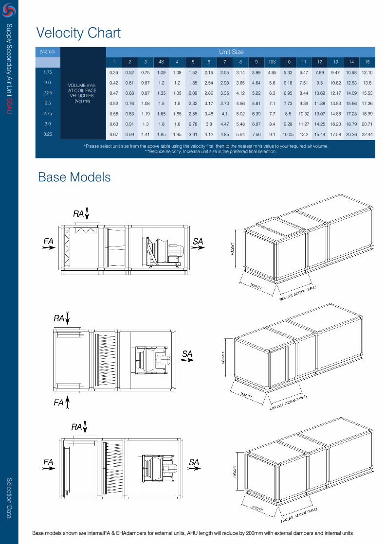
0.36 0.52 0.75 1.09 1.09 1.52 2.16 2.55 3.14 3.99 4.85 5.33 6.47 7.99 9.47 10.98 12.10
0.42 0.61 0.87 1.2 1.2 1.85 2.54 2.98 3.65 4.64 5.6 6.18 7.51 9.5 10.82 12.53 13.8
0.47 0.68 0.97 1.35 1.35 2.09 2.86 3.35 4.12 5.22 6.3 6.95 8.44 10.69 12.17 14.09 15.53
0.52 0.76 1.08 1.5 1.5 2.32 3.17 3.73 4.56 5.81 7.1 7.73 9.39 11.88 13.53 15.66 17.26
0.58 0.83 1.19 1.65 1.65 2.55 3.48 4.1 5.02 6.39 7.7 8.5 10.32 13.07 14.88 17.23 18.99
0.63 0.91 1.3 1.8 1.8 2.78 3.8 4.47 5.48 6.97 8.4 9.28 11.27 14.25 16.23 18.79 20.71
0.67 0.99 1.41 1.95 1.95 3.01 4.12 4.85 5.94 7.56 9.1 10.05 12.2 15.44 17.58 20.36 22.44
*Please select unit size from the above table using the velocity first, then to the nearest m³/s value to your required air volume.**Reduce Velocity, Increase unit size is the preferred final selection.
Velocity Chart
Base Models
(Vc)m/s
VOLUME m³/s AT COIL FACE VELOCITIES
(Vc) m/s
Unit Size1 2 3 4S 4 5 6 7 8 9 10S 10 11 12 13 14 15
1.75
2.0
2.25
2.5
2.75
3.0
3.25
Base models shown are internal FA & EHA dampers for external units, AHU length will reduce by 200mm with external dampers and internal units

Selection D
ataS
upply Secondary A
ir Unit S
SA
U
Fan & Control Configurations
AHU Components

Selection D
ataS
upply Secondary A
ir Unit S
SA
U
Dimension Tables
Dim Size 1 2 3 4S 4 5 6 7 8 9 10S 10 11 12 13 14 15
Additional Components Height & Width
H
W
H
W
Height 25mm Panels
Width 25mm Panels
Height 50mm Panels
Width 50mm Panels
ED External Damper
ID Internal Damper
PF Panel Filter
BF1 Bag 380 - BS EN 16890
BF2 Bag 535 - BS EN 16890
BF3 Bag 635 - BS EN 16890
RBF Rigid Bag Filter
HF HEPA Filter
CF Carbon Filter
HC Frost / LPHW / Pre / Re Heater
EAHB Electric Air Heater Battery
GH Gas Heater
Cooler, DX or CH.W CC
SL
AL
PA
Standard Louvre
Acoustic Louvre
Plenum / Access
2MX 2-Way Mix Damper Sect
AT1 Attenuator
AT2 Duct Mounted Attenuator
HUM Humidifier
BH1 Base Height
BH2 Base Height
RH Roof Height
IICC IInnlelett CCoowlwl
Additional Component Lengths
120
450
300
600
750
850
550
900
900
250
900
1200
550
0
300
600
1050
900
1200
100
150
125
200
600
120
450
300
600
750
850
550
900
900
250
900
1200
550
0
300
600
1050
900
1200
100
150
125
250
700
120 120 120 120
450 450 450 450
300 300 300 300
600 600 600 600
750 750 750 750
850 850 850 850
550 550 550 550
900 900 900 900
900 900 900 900
250 250 250 250
900 900 900 900
1200 1200 1200 1200
550 550 550 550
0 0 0 0
300 300 300 300
600 600 600 600
1050 1350 1350 1350
900 1200 1200 1200
1200 1200 1200 1200
100 100 100 100
150 150 150 150
125 125 125 125
250 250 250 400
800 800 800 800
120
450
300
600
750
850
550
900
900
250
900
1600
550
0
300
600
1350
1200
1200
100
150
125
550
1100
120
450
300
600
750
850
550
900
900
250
900
1600
550
0
300
600
1350
1200
1600
100
150
125
550
1100
120
450
300
600
750
850
550
900
900
250
900
1600
550
0
300
600
1350
1200
1600
100
150
125
550
1300
120
450
300
600
750
850
550
900
900
250
900
1600
550
0
300
600
1350
1200
1600
100
150
125
700
1300
120
450
300
600
750
850
550
900
900
250
900
1600
550
0
300
600
1650
1500
1600
100
150
125
700
1600
120
450
300
600
750
850
550
900
900
250
900
1600
550
0
300
600
1650
1500
1600
100
150
125
700
1600
120
450
300
600
750
850
550
900
900
250
900
1600
550
0
300
600
1650
1500
1600
100
150
125
700
1600
120
450
300
600
750
850
550
900
900
250
900
1600
550
0
300
600
1650
1500
1600
100
150
125
700
1600
120
450
300
600
750
850
550
900
900
250
900
1600
550
0
300
600
1650
1500
1600
100
150
125
700
2200
120
450
300
600
750
850
550
900
900
250
900
1600
550
0
300
600
1650
1500
1600
100
150
125
700
2200
120
450
300
600
750
850
550
900
900
250
900
1600
550
0
300
600
1650
1500
1600
100
150
125
700
2200
610 730 730 1020 730 1020 1360 1360 1360 1670 1970 1670 1970 2400 2400 2400 2400
690 780 1010 1010 1310 1310 1360 1560 1860 1860 1860 2400 2400 2400 2800 3200 3500
650 770 770 1060 770 1060 1360 1360 1360 1670 1970 1670 1970 2400 2400 2400 2400
730 820 1050 1050 1350 1350 1410 1610 1910 1910 1910 2450 2450 2450 2850 3250 3550
1 3 15Dim Size 4S 4 5 6 7 8 9 10S 10 11 12 13 142
EC Fan Sect
Plug Fan Sect
Controls Panel Fan Sect
Controls Panel Fan Sect
Controls Panel Fan Sect
Twin Fan Section
Control Panel Enclosure
900 900 900 1200 900 1400 -
1500 1500 1500 1900 1900 1600 1600 1600 1800 2100 2100
1200 1400 1400 1400 1600 1600 1600 1800 2100 2100
1700 1800 1800 1800
1200 1300 1300 1500 1700 1700 1700 1700 1700 1700 1700 1700 1700
1900 1600 1900 1600 1600 1800 2100 2100
-- - - - -
900 900 900 1200 900 1300
- -
- - - -
- -
-
- -
- -
-
800 800 800 800 800 800 800 800 800 800 800800 800 800 800 800
-
--
- -
800
- -
- - - -
--
-
-- -
-
-
-
- - -
Fan & Control Configurations
ECFS
PFS
TFS
CP1
CPF1
CPF2
CPF3

Selection D
ataS
upply Secondary A
ir Unit S
SA
U
AHU Component Dry Weights kg
1 15Dim Size
4 6 7 9 9 13 17 20 24 29 37 37 44 54 63 72 79
16 20 23 29 29 37 45 51 62 76 104 104 120 172 196 220 240
50 58 66 78 78 92 105 116 134 153 193 193 215 276 308 341 368
BF1 Bag 380 - BS EN 16890
BF2 Bag 535 - BS EN 16890
BF3 Bag 635 - BS EN 16890
RBF Rigid Bag Filter
HF HEPA Filter
Carbon Filter
HC Frost / LPHW / Pre / Re Heater
Battery
GH Gas Heater
Cooler, DX or CH.W CC
SL
AL
PA
Weight of water in coils (kg) = 5.3 x face area m² x number of rows. Cooling generally 4-6 rows, heating generally 1-2 rows.Water
CF
Electric Air HeaterEHAB
80 90 106 131 131 142 158 175 191 220 252 252 277 310 351 387 416
88 102 126 155 155 182 206 223 253 297 364 364 409 466 551 607 660
119 164 219 279 279 368 454 471 563 669 891 891 1060 1210 1692 1838
46 53 64 75 75 91 106 120 138 158 193 193 219 253 281 315 341
84 97 107 140 140 167 177 235 246 263 290 290 300 315 465 481 493
88 94 141 180 180 236 296 348 409 488 622 622 728 880 991 1129 1231
4 6 7 9 9 13 17 20 24 29 37 37 44 54 63 72 79
75 84 96 110 110 122 135 146 160 172 198 198 213 232 251 270 285
107 123 147 174 174 212 252 287 324 375 460 460 523 612 715 819 876
140 161 193 229 229 279 332 378 427 495 606 606 691 808 945 1083 1158
109 118 130 144 144 190 203 214 228 274 375 375 421 450 530 559 582
5 5 5 5 5
10 10 10 10
24
5
10 10 10 10 10 10 10 10 10 10
24 34 43 43 43 43 51 58 63--
6 6 6 6 6 6 10 10 10 10 15 15 15 15 15 20 20
7 7 7 7 7 7 11 11 11 11 16 16 16 16 16 22 22
10 11 14 17 17 17 19 23 23 28 28 28 28 32 36 4018
81 91 107 132 132 143 159 176 192 221 253 253 278 311 352 388 417
46 53 64 75 75 91 106 120 138 158 193 193 219 253 281 315 341
24 26 27 29 29 33 37 40 44 49 57 57 64 74 83 92 99
5
10
5
- - -
IC Inlet Cowl
ED External Damper
ID Internal Damper
PF Panel Filter
AT1 Attenuator
AT2 Duct Mounted Attenuator
HUM Humidifier
BH1 Base 100mm High 1000L
BH2 Base 150mm High 1000L
RH Roof Section 1000L
Floor Grid 1000W
25mm Acoustic Treatment
50mm Acoustic Treatment
32 38 46 51 51 57 63 77 84 91 111 111 126 142 189 211 227
Standard Louvre
Acoustic Louvre
Plenum/Access
- -
5
10
5 5 5
10
5 5 5 5 5
--
1512
2 3 4S 4 5 6 7 8 9 10S 10 11 12 13 14
Additional Components
2MX 2-Way Mix Damper Sect 67 93 121 142 142 165 249 273 357 397 546 546 585 695 907 988 1053
Fan & Control Configuration Weights kg
1 3 15Dim Size 4S 4 5 6 7 8 9 10S 10 11 12 13 142
EC Fan Sect
Plug Fan Sect
Controls Panel Fan Sect
Controls Panel Fan Sect
Controls Panel Fan Sect
Twin Fan Section
Control Panel Enclosure
133 147 165 241 187 314 -
483 510 545 812 1015 797 993 1042 1177 1370 1412
432 563 590 652 820 860 910 1193 1483 1743
249 309 345 414
281 378 458 535 623 780 979 860 1063 1116 1175 1230 1264
763 753 954 900 949 1237 1523 1783
-- - - - -
140 173 191 290 212 359
- -
- - - -
- -
-
- -
- -
-
201 234 242 268 294 294 314 338 384 410 426110 122 138 161 182
-
--
- -
161
- -
- - - -
--
-
-- -
-
-
-
- - -
Fan & Control Configurations
ECFS
PFS
TFS
CP1
CPF1
CPF2
CPF3
Weight of fan sections shown are with the largest fan possible for each size section. Weight will reduce when using a smaller fan or fans.
98 110 130 160 160 173 193 214 233 268 307 307 338 378 428 472 507
108 120 142 176 176 190 211 235 256 294 338 338 371 416 470 518 557
Selection D
ataS
upply Secondary A
ir Unit S
SA
U
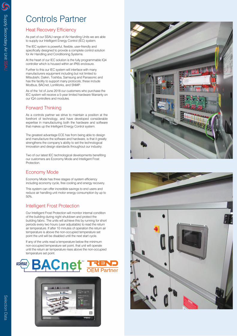
Controls PartnerHeat Recovery EfficiencyAs part of our SSAU range of Air Handling Units we are able to supply our Intelligent Energy Control (IEC) system.
The IEC system is powerful, flexible, user-friendly and specifically designed to provide a complete control solution for Air Handling and Conditioning Systems.
At the heart of our IEC solution is the fully programmable IQ4 controller which is housed within an IP65 enclosure.
Further to this our IEC system will interface with many manufacturers equipment including but not limited to Mitsubishi, Daikin, Toshiba, Samsung and Panasonic and has the facility to support many protocols; these include Modbus, BACnet, LonWorks, and SNMP.
As of the 1st of June 2018 our customers who purchase the IEC system will receive a 5-year limited hardware Warranty on our IQ4 controllers and modules.
Forward ThinkingAs a controls partner we strive to maintain a position at the forefront of technology, and have developed considerable expertise in manufacturing both the hardware and software that makes up the Intelligent Energy Control system.
The greatest advantage ECE has from being able to design and manufacture the software and hardware, is that it greatly strengthens the company’s ability to set the technological innovation and design standards throughout our industry.
Two of our latest IEC technological developments benefiting our customers are Economy Mode and Intelligent Frost Protection.
Economy ModeEconomy Mode has three stages of system efficiency including economy cycle, free cooling and energy recovery.
This system can offer incredible savings to end users and reduce air handling unit motor energy consumption by up to 50%.
Intelligent Frost ProtectionOur Intelligent Frost Protection will monitor internal condition of the building during night shutdown and protect the building fabric. The units will achieve this by running for short periods every two hours (user adjustable) to read the return air temperature. If after 10 minutes of operation the return air temperature is above the non-occupied temperature set point the unit will be disabled until the next start cycle.
If any of the units read a temperature below the minimum non-occupied temperature set point, that unit will operate until the return air temperature rises above the non-occupied temperature set point.

Selection D
ataS
upply Secondary A
ir Unit S
SA
U
Air Handling Unit ConstructionAt ECE UK we have improved the design of our equipment over
the last forty years offering a cost-effective solution including L2
Leakage Class, D1 Deflection Class, TB1 Thermal Bridging and T2
thermal Transmittance. This is complimented by achieving
standards set out in ERP 2016/18 and L2 Specific Fan Power.
To further ensure structural stability, rigidity and thermal qualities
BS EN 1886:2007 standard provides the means for classifying the
performance of all our air handling units.
The Air Handling Unit framework is constructed from a closed
aluminium box section with heavy duty injection moulded ABS
black nylon knock in corner pieces. This high density and
lightweight structure ensures a strong and rigid framework for the
Air Handling Unit.
Depending upon the project requirements panels can be either
25mm or 50mm thick. Panels are constructed from a galvanised
sheet steel inner skin with a plastisol coated or galvanised sheet
steel outer skin with mineral wool insulation sandwiched between
the sheets. Our standard plastisol colour is Goosewing Grey
RAL10A05, other colours are available on request.
Our standard mineral wool insulation has a density of 100kg/m3.
As standard each complete unit or modular section would be
factory assembled on a full perimeter base to ensure full structural
stability.
All externally mounted units would be fully sealed and completed
with an overhanging pitched roof to prevent water ingress.
Depending upon site access all of our Air Handling Units can be
supplied as modular sections, component form or fully assembled
on a single piece base frame and still conform to the standards
set out above.
This allows building maintenance teams, consultants and
contractors unique access to one of the most productive
portals available.
Here is just some of the great features that our portal offers:
• 3D models to go into your Building Management System,such as Revit (.step, .sat, .ifc, .dwg (3D), etc).
• 3D models that can be interacted with in real-time usingaugmented reality devices (such as a MicrosoftHoloLens).
• 2D Certified Drawings (.dwg for loading into AutoCAD /DraftSight and .pdf for opening on any device, anywhere).
• Consumables Information (such as Filters, Motors,Sensors and Actuators).
• Single click Basket for consumables with Anything AirHandling, our Spares & Parts shop www.aahuk.com.
• Controls Documents (if your AHU has one of our controlspackage).
• Refrigeration Unit Information.
• Installation, Operation and Maintenance Manual.
• Recycling Manual.
All you need to access this information is a unique reference
number and an email address. To make it really easy each of
our units now come with an Asset Information plate allowing
you on-premises access to all the information from your
mobile device.
TRY IT! Scan the QR and enter the code
Asset InformationThis AHU mounted web based portal augments our customer
experience by providing you with all your BIM Level 2 files for
your job specific, bespoke, Air Handling Unit as defined at
the design stage.

ECE UK Ltd.
T
E
W
A
+44 (0)1634729690
www.eceuk.com
Pharaoh House, Arnolde
Close, Rochester, Kent,
ME2 4QW
© 2019 ECE UK Ltd.
on a DX system the indoor coil is mounted internal to the AHU and outdoor coil is the condensing unit.
when matching indoor to outdoor coils HEX volume, Air Volume, Coil Capacity and Coil Circuitry should match.
at peak times during summer and winter, outdoor coil capacities on DX systems can reduce by up to 20%. Dependent on ambient temperatures.
minimum air on temperature in heating mode for a DX system indoor coil is 10°C.
swings in temperature are often caused by DX run on times and single circuit DX systems supplying small areas. This is more prevalent in small areas and with air volumes below 1.0 m³/s. Twin circuits will often reduce the risk of this happening.
by supplying twin circuits you reduce the risk of cold air being pumped into the area served when one circuit is in defrost.
some DX units have eleven capacity steps whereas others may only have five.
the term "vertical unit" has the same meaning as double stacking and or piggy back arrangement.
if you're concerned about the equipment access route, ECE can offer a free site survey.
ECE can offer a long reach HIAB vehicle with a reach of 27 meters holding one tonne.
if ECE supply the AHU, Controls and DX equipment the AHU warranty is extended to two years.
ECE offer a 5 year warranty on its iQ range of controllers.
ECE offer a 5 year warranty on its DX units.
ErP requires supply systems to have minimum ePM 2.5 50% grade filtration.
Location, Internal or External.
Delivery in modules or packaged in one piece (dimensions limits apply).
Units also available “Dry Built” for site off load, dismantle, carry through, re-assemble, join and seal.
Units also available in component form for site offload, carry through, re-assemble, join and seal.
Fewer pressure producing components reduces the overall energy consumption thus reducing carbonfootprint, SFP and running costs of the AHU.
AHU cooler and heater duties will incorporate coolth and heat recovery capacity and reduce the size ofthe indirect or direct heating and cooling equipment. This will reduce the indirect or direct heating andcooling equipment cost to the client by up to 20%.
AHU’s can include EC Fans (IE4 Motors) to give the highest possible efficiency and the lowest life cyclecost.