first supplementary master prospectus dated 30 december 2016

SUPPLEMENTARY MASTER MUNICIPAL CONSTRUCTION DOCUMENTS
SUPPLEMENTARY GENERAL CONDITIONS
SUPPLEMENTARY SPECIFICATIONS
SUPPLEMENTARY STANDARD DRAWINGS
JANUARY 2016
ENGINEERING DEPARTMENT
( )


Engineering Department
Supplementary Master Municipal Construction Documents
SUPPLEMENTARY GENERAL CONDITIONS
January 2016
The City of Surrey Supplementary Master Municipal Construction Documents are supplemental to the Master Municipal Construction Document – Platinum Edition (2009) and take precedence over the General Conditions, Specifications, Standard Detail Drawings and their Amendments.


CITY OF SURREY TABLE OF CONTENTS & CONCORDANCE INDEX MMCD SGC ENGINEERING DEPARTMENT PAGE i SUPPLEMENTARY GENERAL CONDITIONS JANUARY 2016
TABLE OF CONTENTS PAGE
1.0 DEFINITIONS ............................................................................................................................ 1
1.1 ABNORMAL WEATHER ........................................................................................................... 1 1.76 VARIANCE THRESHOLD PERCENTAGE ........................................................................................ 1 1.79 ARCHAEOLOGICAL ARTIFACTS .................................................................................................. 1 1.80 COMMENCEMENT DATE ......................................................................................................... 1 1.81 FOREIGN MATERIAL ............................................................................................................... 1 1.82 HIGHWAY ............................................................................................................................ 1 1.83 PUBLIC ART .......................................................................................................................... 1 1.84 SUPPLEMENTARY GENERAL CONDITIONS (SGC) ......................................................................... 1 1.85 SUPPLEMENTARY GENERAL CONDITIONS, PROJECT (SGCP) .......................................................... 2 1.86 SUPPLEMENTARY SPECIFICATIONS (SS) ..................................................................................... 2 1.87 SUPPLEMENTARY SPECIFICATIONS, PROJECT (SSP)...................................................................... 2 1.88 UTILITIES .............................................................................................................................. 2
2.0 DOCUMENTS ........................................................................................................................... 3
2.1 EXECUTION .......................................................................................................................... 3 2.2 INTERPRETATION ................................................................................................................... 3
3.0 CONTRACT ADMINISTRATOR ................................................................................................... 3
3.3 CONTRACT ADMINISTRATION .................................................................................................. 3
4.0 CONTRACTOR .......................................................................................................................... 4
4.1 CONTROL OF WORK ............................................................................................................... 4 4.2 SAFETY ................................................................................................................................ 4 4.3 PROTECTION OF WORK, PROPERTY AND THE PUBLIC ................................................................... 4 4.6 CONSTRUCTION SCHEDULE ..................................................................................................... 8 4.7 SUPERINTENDENT .................................................................................................................. 9 4.12 TESTS AND INSPECTIONS ......................................................................................................... 9
7.0 CHANGES ............................................................................................................................... 10
7.4 OPTIONAL WORK ................................................................................................................ 10
9.0 VALUATION OF CHANGES AND EXTRA WORK ........................................................................ 10
9.4 QUANTITY VARIATIONS ........................................................................................................ 10
10.0 FORCE ACCOUNT ................................................................................................................... 10
10.1 FORCE ACCOUNT COSTS ....................................................................................................... 10
11.0 CONCEALED OR UNKNOWN CONDITIONS .............................................................................. 11
11.1 DEFINITION ........................................................................................................................ 11 11.4 ACKNOWLEDGMENT ............................................................................................................ 11 11.5 ARCHAEOLOGICAL ARTIFACTS ................................................................................................ 12
12.0 HAZARD MATERIALS .............................................................................................................. 12
12.2 DISCOVERY OF HAZARDOUS MATERIALS .................................................................................. 12 12.4 CONTRACT ADJUSTMENT FOR HAZARDOUS MATERIALS ............................................................. 12
13.0 DELAYS .................................................................................................................................. 12

CITY OF SURREY TABLE OF CONTENTS & CONCORDANCE INDEX MMCD SGC ENGINEERING DEPARTMENT PAGE ii SUPPLEMENTARY GENERAL CONDITIONS JANUARY 2016
13.8 DIRECTION TO STOP OR DELAY .............................................................................................. 12 13.9 LIQUIDATED DAMAGES FOR LATE COMPLETION ........................................................................ 13
15.0 OWNER’S RIGHT ON CONTRACTOR’S DEFAULT ...................................................................... 14
15.2 NOTICE OF DEFAULT ............................................................................................................ 14 15.3 TERMINATION ..................................................................................................................... 14
16.0 CONTRACTOR’S RISK ON OWNER’S DEFAULT ......................................................................... 15
16.2 WORK STOPPAGE ................................................................................................................ 15 16.4 TERMINATION ..................................................................................................................... 15
17.0 DISPUTES ............................................................................................................................... 16
17.5 REFEREE ............................................................................................................................ 16
18.0 PAYMENT .............................................................................................................................. 16
18.5 PAYMENT ........................................................................................................................... 16
20.0 LAWS, NOTICES, PERMITS, AND FEES ..................................................................................... 16
20.2 PERMITS ............................................................................................................................ 16 20.4 FEES .................................................................................................................................. 16
21.0 WORKERS COMPENSATION REGULATION .............................................................................. 17
21.1 EVIDENCE OF COMPLIANCE ................................................................................................... 17 21.2 CONTRACTOR IS “PRIME CONTRACTOR” .................................................................................. 17 21.3 COMPLIANCE WITH WORKERS COMPENSATION REQUIREMENTS ................................................. 18
22.0 INDEMNIFICATION ................................................................................................................. 19
22.1 CONTRACTOR TO INDEMNIFY ................................................................................................. 19
24.0 INSURANCE ........................................................................................................................... 19
24.1 REQUIRED INSURANCE ......................................................................................................... 19
27.0 PATENTS AND COPYRIGHTS ................................................................................................... 21
27.1 PATENT AND COPYRIGHT COMPLIANCE ................................................................................... 21
28.0 NON‐RESIDENTS .................................................................................................................... 22
28.1 NON‐RESIDENTS ................................................................................................................. 22

CITY OF SURREY SUPPLEMENTARY GENERAL CONDITIONS MMCD SGC ENGINEERING DEPARTMENT PAGE 1 SUPPLEMENTARY GENERAL CONDITIONS JANUARY 2016
1.0 DEFINITIONS 1.1 Abnormal
Weather
Delete 1.1.1 and replace with
“Abnormal Weather” means temperature, precipitation, wind or other weather condition, as determined by the Contract Administrator, that prevents the Contractor from proceeding with at least 60% of the normal labour and equipment force, for at least 5 hours on a component of the work, which if delayed is on the critical path of the schedule and as such will delay the completion of the Work.
1.76 Variance Threshold Percentage
Delete 1.76.1 and replace with
Variance Threshold Percentage is not applicable to any unit rate, whether it is for the benefit of the Owner or the Contractor.
1.79 Archaeological Artifacts
Add 1.79.1 "Archaeological Artifacts" means any fossils, artifacts, coins, articles of value or antiquity, remains, and other things of geological, archaeological or historical interest or value discovered at the Place of the Work.
1.80 Commencement Date
Add 1.80.1 “Commencement Date” has the meaning set out in paragraph 5.1.2 of the Form of Tender.
1.81 Foreign Material Add 1.81.1 “Foreign Material” with respect to SGC 11.0 is limited specifically to the following: multiple layers of asphalt or concrete pavement resulting in a cumulative thickness in excess of 300mm; buried railway ties and tracks; and buried corduroy roads. It does not include Utilities, rocks, stumps and other subsurface conditions.
1.82 Highway Add 1.82.1 “Highway” includes a street, road, lane, bridge, thoroughfare, sidewalk, boulevard, viaduct and any other way open to public use.
1.83 Public Art Add 1.83.1 “Public Art” means publicly accessible original art that the Owner separately contracts and is created and/or installed at or near the Work.
1.84 Supplementary General Conditions (SGC)
Add 1.84.1 SGC means those City of Surrey Supplementary General Conditions (SGC’s), made up of paragraphs and subparagraphs with the same numbering as the Master Municipal Construction Documents, which are supplementary to and superseding to GC’s.

CITY OF SURREY SUPPLEMENTARY GENERAL CONDITIONS MMCD SGC ENGINEERING DEPARTMENT PAGE 2 SUPPLEMENTARY GENERAL CONDITIONS JANUARY 2016
1.85 Supplementary General Conditions, Project (SGCP)
Add 1.85.1 SGCP means project specific supplementary general conditions, made up of paragraphs and subparagraphs with the same numbering as the Master Municipal Construction Document, which are supplementary to and superseding SGC’s and GC’s.
1.86 Supplementary Specifications (SS)
Add 1.86.1 SS means those City of Surrey Supplementary Specifications (SS), made up of paragraphs and subparagraphs with the same numbering as the Master Municipal Construction Documents, which are supplementary to and superseding the Master Municipal Specifications.
1.87 Supplementary Specifications, Project (SSP)
Add 1.87.1 SSP means project specific supplementary specifications, made up of paragraphs and subparagraphs with the same beginning paragraph numbers as the Master Municipal Construction Document, which are supplementary to and superseding the SS’s and Master Municipal Specifications.
1.88 Utilities Add 1.88.1 “Utilities” is used broadly and includes but is not limited to any and all lines, poles, structures, facilities, infrastructure works, utilities for power, cable TV, telephone, telecommunications and data transmission, all sanitary and drainage infrastructure, all water, oil, gas and electric services, all steam pipes and services, all survey monuments, street lights, traffic lights, traffic detector loops embedded in pavement, rail tracks, and all related infrastructure, whether located above or below ground, whether visible or invisible, whether man‐made or natural.

CITY OF SURREY SUPPLEMENTARY GENERAL CONDITIONS MMCD SGC ENGINEERING DEPARTMENT PAGE 3 SUPPLEMENTARY GENERAL CONDITIONS JANUARY 2016
2.0 DOCUMENTS 2.1 Execution Delete 2.1.1 and
replace with The Owner shall deliver the Contract Documents, in a form ready for signing, to the Contractor within 15 Days after receipt of all information required to be submitted by the Contractor as set out in paragraph 5.1.1 of the Form of Tender.
2.2 Interpretation Delete 2.2.4(1) and replace with
(1) the Contract Documents shall govern and take precedence in the following order with the Agreement taking precedence over all other Contract Documents: a) Agreement b) Addenda c) Supplementary General Conditions, Project d) Supplementary General Conditions e) General Conditions f) Supplementary Specifications, Project g) Supplementary Specifications h) Specifications i) Drawings list in Schedule 2 to the Agreement j) Supplementary Detail Drawings k) Standard Detail Drawings l) Executed Form of Tender m) Instructions to Tenderers n) All other Contract Documents;
3.0 CONTRACT ADMINISTRATOR 3.3 Contract
Administration Append to 3.3.5 The minimum replacement cost from the Contractor
to the Owner, for City of Surrey owned monuments, shall be as follows, inclusive of taxes, or as amended by the City of Surrey on an annual basis: a) ISA Monument ‐ $1,820 b) High Precision Secondary Benchmark ‐ $3,275 c) High Precision Network Benchmark ‐ $7,535
CITY OF SURREY SUPPLEMENTARY GENERAL CONDITIONS MMCD SGC ENGINEERING DEPARTMENT PAGE 4 SUPPLEMENTARY GENERAL CONDITIONS JANUARY 2016
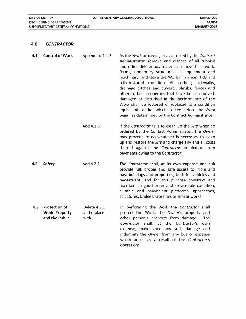
4.0 CONTRACTOR 4.1 Control of Work Append to 4.1.2 As the Work proceeds, or as directed by the Contract
Administrator, remove and dispose of all rubbish and other deleterious material, remove false‐work, forms, temporary structures, all equipment and machinery, and leave the Work in a clean, tidy and fully‐restored condition. All curbing, sidewalks, drainage ditches and culverts, shrubs, fences and other surface properties that have been removed, damaged or disturbed in the performance of the Work shall be restored or replaced to a condition equivalent to that which existed before the Work began as determined by the Contract Administrator.
Add 4.1.3 If the Contractor fails to clean up the Site when so ordered by the Contact Administrator, the Owner may proceed to do whatever is necessary to clean up and restore the Site and charge any and all costs thereof against the Contractor or deduct from payments owing to the Contractor.
4.2 Safety Add 4.2.2 The Contractor shall, at its own expense and risk provide full, proper and safe access to, from and past buildings and properties, both for vehicles and pedestrians, and for this purpose construct and maintain, in good order and serviceable condition, suitable and convenient platforms, approaches, structures, bridges, crossings or similar works.
4.3 Protection of Work, Property and the Public
Delete 4.3.1 and replace with
In performing the Work the Contractor shall protect the Work, the Owner's property and other person's property from damage. The Contractor shall, at the Contractor's own expense, make good any such damage and indemnify the Owner from any loss or expense which arises as a result of the Contractor's operations.

CITY OF SURREY SUPPLEMENTARY GENERAL CONDITIONS MMCD SGC ENGINEERING DEPARTMENT PAGE 5 SUPPLEMENTARY GENERAL CONDITIONS JANUARY 2016
Delete 4.3.4 and replace with
The Owner does not possess complete or accurate information with respect to the occurrence or the location of existing Utilities that will or may be encountered by the Contractor during the performance of the Work. Any plans, surveys, maps or descriptions of Utilities given to the Contractor, verbal or otherwise, are intended only as an aid to assist the Contractor in locating these construction obstacles. However, the Contractor is solely responsible to take all steps necessary to investigate, locate, verify and protect all Utilities. Before commencing Work the Contractor shall: (1) Complete a BC One Call at least 48 hours in
advance. (2) Expose and determine conclusively in the
field the location, elevation, dimensions and material type of all underground Utilities and structures indicated on the Contract Documents as being at the Place of Work.
(3) Consult with all utility corporations that provide electricity, communication, gas or other utility services in the area of the Place of the Work, to similarly expose and conclusively determine the location of all underground Utilities for which they have records; and
(4) Similarly expose and conclusively determine the location of any other Utilities or underground structures that are reasonably apparent in an inspection of the Place of the Work.
Append to 4.3.5 The Contractor hereby indemnifies and saves the
Owner, its elected and appointed officials, employees and agents harmless from and against all liabilities, actions, causes of action, claims, damages, expenses, costs, debts, demands or losses suffered or incurred by them or any of them, including consequential damages and damages to third parties, whether known or unknown, foreseeable or not, for which the Owner or any of them might be liable arising from the provision of or failure to provide information regarding Utilities.

CITY OF SURREY SUPPLEMENTARY GENERAL CONDITIONS MMCD SGC ENGINEERING DEPARTMENT PAGE 6 SUPPLEMENTARY GENERAL CONDITIONS JANUARY 2016
Delete 4.3.6 and replace with
In performing Work on or near Utilities, or where it is necessary to cut, move or alter any Utilities, the Contractor shall communicate and make arrangements with the proper authorities and perform the Work in compliance with any direction or instruction received from that authority. Any damage to Utilities by the Contractor shall be repaired at the Contractor's expense. Where Utilities are serving the public while construction is in progress, it shall be the responsibility of the Contractor to plan and execute the Work such that there is no disruption of service by such Utilities.
Add 4.3.7 In performing Work on or near third‐party Utilities (BC Hydro, CN Rail, CP Rail, Fiber Optic Fortis, Kinder Morgan, Metro Vancouver, Southern Rail, Shaw, Telus, etc.), or where it is necessary to cut, move or alter these Utilities, the Contractor shall communicate and coordinate with the third‐party companies or authorities as it relates to schedule, timing, site safety and compliance in the utility alterations or relocations as part of performing the overall Work. If the alteration of these Utilities impacts the project schedule, the Contractor shall allow sufficient time for the companies or authorities to relocate their Utilities. It is the Contractor’s responsibility to ensure all Work, including third‐party utility relocations, is coordinated and completed in a reasonable time as part of the overall Work. In the event the Contractor has been diligent and made significant effort and attempts in coordinating with the third‐party companies or authorities and having their relocations accelerated, any and all costs incurred as a result of the third‐party companies’ ability, or inability, to relocate the Utilities are considered incidental and any such Delays are considered Unavoidable Delays as per GC 13.3 and beyond the reasonable control of the Owner.

CITY OF SURREY SUPPLEMENTARY GENERAL CONDITIONS MMCD SGC ENGINEERING DEPARTMENT PAGE 7 SUPPLEMENTARY GENERAL CONDITIONS JANUARY 2016
Add 4.3.8 Contractor shall not deposit any material upon any Highway without first obtaining the approval of the Contract Administrator to the location, manner of placement, nature and amount of the material to be deposited and length of time for placement of the material.
Add 4.3.9 Where any part of the Work is to be performed on private property, it is the responsibility of the Owner to arrange for and acquire required access. The Contractor shall not perform Work on any private property until the Contract Administrator has confirmed to the Contractor in writing that the Work thereon may proceed. While it is anticipated that the Owner will be able to arrange required access to private property, the Contractor shall plan their work accordingly to mitigate delays and shall be flexible in accommodating delays or Changes in the sequence or schedule of the Construction Schedule, with no extensions in Contract Time nor Contract Price to the Contractor.
Add 4.3.10 On completion of Work in a right‐of‐way or on private property, the Contractor shall deliver to the Contract Administrator, a formal release in writing, in a form provided by the Owner, signed by each owner of private property on which the Work was performed, verifying that the Contractor has cleaned up the private property to the owner’s satisfaction and that the property owner(s) has no claim upon the Contractor or the Owner as a result of the Work.
Add 4.3.11 The Contractor shall keep all portions of the Work properly and efficiently drained during construction until Total Performance and in compliance with any by‐laws or requirements of the Owner.

CITY OF SURREY SUPPLEMENTARY GENERAL CONDITIONS MMCD SGC ENGINEERING DEPARTMENT PAGE 8 SUPPLEMENTARY GENERAL CONDITIONS JANUARY 2016
Add 4.3.12 The Contractor shall protect and maintain access to all existing utilities, properties, solid waste collection receptacles, and mailboxes at all times during construction, including a minimum 1.5m wide and flat accessible path with no safety concerns. If access cannot be maintained, the Contractor shall make suitable arrangement for access as requested by the Contract Administrator, including solid waste collection and delivery of mail to the residents affected.
Add 4.3.13 The Contractor shall, at its own expense and risk, deliver to businesses and residents copies of letters provided to the Contractor by the Owner, advising these persons of intended construction activities. The Contractor shall deliver these letters no sooner than ten (10) Days and no later than five (5) Days before the start of construction in the affected area.
Add 4.3.14 The Contractor is responsible for the maintenance and repair of any Highway affected by the Work, including Highways used for hauling, trucking and delivery.
Add 4.3.15 Work on a Highway shall be carried out in such a manner that will not affect traffic on any Highway or prevent access to property fronting on the Highway without first having obtained written permission to do so from the authorities having jurisdiction. In that regard, the Contractor shall perform its Work in strict compliance with the requirements, rules, regulations and by‐laws of any Federal, Provincial or municipal authority having jurisdiction.
4.6 Construction Schedule
Add 4.6.8 In instances where the Contractor is double‐shifting, as determined to be either working longer than 12 hours per day or in any 24‐hour period, then 2 Days, or Work Days, will be deducted from the Contract Time for every calendar day when such activity is completed.

CITY OF SURREY SUPPLEMENTARY GENERAL CONDITIONS MMCD SGC ENGINEERING DEPARTMENT PAGE 9 SUPPLEMENTARY GENERAL CONDITIONS JANUARY 2016
The Contractor may apply for exemptions to the noise by‐law in order to perform portions of the Work at night, however the Owner does not guarantee that exemptions will be granted, nor shall the Contractor rely on exemptions being permitted in order to complete the Work in accordance with the Construction Schedule.
Add 4.6.9 The Contractor shall not work on the Site, or deliver materials, for which delivery slips (i.e. weigh tickets) are the basis of payment, unless the Contract Administrator or his site inspector is present.
4.7 Superintendent Append to 4.7.2
The Superintendent shall be in attendance at all times at the Place(s) of the Work unless permitted otherwise by the Contract Administrator.
Add 4.7.4 Unless otherwise permitted by the Owner, the
Superintendent shall be the person named in Appendix 3 in the tender submission documents.
4.12 Tests and Inspections
Delete 4.12.1 and replace with
The Contractor is solely responsible for ensuring that the Work is performed in accordance with the requirements of the Contract Documents. The Contractor shall perform or cause to be performed all tests, inspections and approvals of the Work as required by the Contract Documents or as required by the Contract Administrator as part of the Quality Control. Any reference in the specifications to inspection and testing shall mean that the Work described in the specification must be inspected and tested in a manner approved by the Contract Administrator. The Contractor shall only employ or engage, as an agent or consultant for testing, a person approved by the Owner. Where the specification indicates that the Contract Administrator will arrange for testing, the Contractor continues to be solely responsible for testing of the Work. Upon immediate completion of each test, certified copies of each test shall be submitted by the testing laboratory directly to the Contract Administrator. The Contract Administrator may perform additional tests for the Owner’s sole benefits. The costs of these tests will be the responsibility of the Owner.

CITY OF SURREY SUPPLEMENTARY GENERAL CONDITIONS MMCD SGC ENGINEERING DEPARTMENT PAGE 10 SUPPLEMENTARY GENERAL CONDITIONS JANUARY 2016
Append to 4.12.10
If the Contractor performs Work for more than 10 hours per Day, or work shift, overtime costs incurred by the Owner to complete tests, inspections and payment measurements may be charged, at the sole discretion of the Owner, to the Contractor.
7.0 CHANGES 7.4 Optional Work Append to
7.4.1 If Optional Work is performed prior to the Contractor achieving Substantial Performance, there shall be no adjustments to the Contract Time.
9.0 VALUATION OF CHANGES AND EXTRA WORK 9.4 Quantity
Variations Delete 9.4.1 and replace with
The respective amounts of work and services to be done and carried out and materials to be furnished in the Schedule of Quantities and Prices is an estimate for the purpose of comparing tenders only. The Owner does not expressly, nor by implication, agree that the actual amounts of work will correspond even approximately to this estimate, but reserves the right to increase or decrease the amounts of any and all tender items in the Schedule of Quantities and Prices, and to omit portions of the Work that may be deemed unnecessary by the Contract Administrator. The Contractor shall make no claim for adjustments in unit prices, anticipated profits, for loss of profit, for overhead, for damages, or for any extra payment whatsoever, except as provided herein, because of any difference between the amount of actual work done and material actually furnished and the quantities stated in the Schedule of Quantities and Prices.
10.0 FORCE ACCOUNT 10.1 Force Account
Costs Append to 10.1.1 (1)
Costs for the Contractor’s Superintendent, Project Managers, Health and Safety Personnel, and Office/Administration Staff are not eligible labour costs as those costs are considered incidental to the mark up owing for overhead on labour.

CITY OF SURREY SUPPLEMENTARY GENERAL CONDITIONS MMCD SGC ENGINEERING DEPARTMENT PAGE 11 SUPPLEMENTARY GENERAL CONDITIONS JANUARY 2016
11.0 CONCEALED OR UNKNOWN CONDITIONS 11.1 Definition Delete 11.1.1
and replace with
A "Concealed or Unknown Condition" is either Archaeological Artifacts, Foreign Material or Hazardous Materials, all as defined in GC and SGC paragraph 1.0, that: (1) occur at the Place of Work; and (2) materially affects the cost of, or the time
required for, the performance of the Work; and
(3) differs materially from conditions disclosed in the Contract Documents, and was not apparent in an examination of the Place of the Work or could not be reasonably inferred from geotechnical examinations and as‐built utility records.
Add 11.1.2 The risk of, responsibility and liability for Utilities and subsurface soil conditions and groundwater conditions, known or unknown, rests solely with the Contractor. The Contractor acknowledges and agrees that it has not relied on the accuracy or completeness of any data or information provided by or on behalf the Owner in assessing these risks except those defined in SGC 11.1.1 hereof and the Contract Price for the Work includes for these risks.
11.4 Acknowledgment Add 11.4.1 The Contractor acknowledges and agrees that it has not relied on the accuracy or completeness of any data or information provided by or on behalf of the Owner in assessing the risks of a Concealed or Unknown Condition.
Add 11.4.2 The Contractor acknowledges and agrees that it
has conducted its own independent investigation and has taken into account the risks of a Concealed or Unknown Condition.

CITY OF SURREY SUPPLEMENTARY GENERAL CONDITIONS MMCD SGC ENGINEERING DEPARTMENT PAGE 12 SUPPLEMENTARY GENERAL CONDITIONS JANUARY 2016
11.5 Archaeological Artifacts
Add 11.5.1 Any Archaeological Artifacts discovered by the Contractor shall, as between the Owner and the Contractor, be deemed to be the absolute property of the Owner.
Add 11.5.2 The Contractor shall immediately advise the Contract Administrator of the discovery by the Contractor of any Archaeological Artifacts and take all reasonable precautions to protect and preserve same.
12.0 HAZARD MATERIALS 12.2 Discovery of
Hazardous Materials
Delete 12.2.2 and replace with
If the Contract Administrator observes any materials at the place of the Work that the Contract Administrator knows or suspects may be Hazardous Materials then the Contact Administrator shall immediately give written notice to the Contractor and the Contractor shall immediately stop the Work or portion of the Work as required by GC 12.2.1 (1)
12.4 Contract Adjustment for Hazardous Materials
Append to 12.4.2
However, the Contractor is not entitled to payment of any delay costs associated with suspected or confirmed Hazardous Materials.
13.0 DELAYS 13.8 Direction to
Stop or Delay Delete 13.8.2 and replace with
During any such stoppage or delay, the Contractor shall be responsible to protect the Work. The Contractor shall not be entitled to an extension to schedule or claim for costs if the direction to Stop or delay was due to work being performed that was inconsistent with the Contract Documents or as a result of a safety hazard as deemed by the Contract Administrator or Owner or Work Safe BC.

CITY OF SURREY SUPPLEMENTARY GENERAL CONDITIONS MMCD SGC ENGINEERING DEPARTMENT PAGE 13 SUPPLEMENTARY GENERAL CONDITIONS JANUARY 2016
13.9 Liquidated Damages for Late Completion
Delete 13.9.1 and replace with
If the Contractor fails to meet the Milestone Date for Substantial Performance, or any other specified Milestone Date, as set out in the Form of Tender paragraph 2.2, as may be adjusted pursuant to the provisions of the Contract Documents, then the Owner may deduct from any monies owing to the Contractor for the Work: (1) as a genuine pre‐estimate for the Owner’s
increased costs for the Contract Administrator and their field representative caused by such delay an amount of $1500 per calendar day, or pro rata portion, for:
a. each day that the Work, or portion of Work, was completed after the specified Milestone Date for that applicable Work, or portion of Work; and
b. each day that actual Substantial Performance is achieved after the Substantial Performance Milestone Date; plus
(2) all direct out of pocket costs, such as, but not
limited to: the Owner’s own staff costs; costs for safety, security, or equipment rental required; and costs for temporary surface restoration and increased temporary maintenance which may be reasonably incurred by the Owner as direct result of such delay; plus
(3) any loss to the Owner of third‐party funding
which the Owner was to receive if the Work, or a particular portion thereof, was not completed before a Milestone Date.
If the monies owing to the Contractor are less than the total amount owing by the Contractor to the Owner under (1), (2) or (3) then any shortfall shall immediately, upon written notice from the Owner, and upon Substantial Performance, be due and owing by the Contractor to the Owner.

CITY OF SURREY SUPPLEMENTARY GENERAL CONDITIONS MMCD SGC ENGINEERING DEPARTMENT PAGE 14 SUPPLEMENTARY GENERAL CONDITIONS JANUARY 2016
15.0 OWNER’S RIGHT ON CONTRACTOR’S DEFAULT 15.2 Notice of
Default Delete 15.2.1 and replace with
On the occurrence of any one or more of the following events: (1) it is discovered that any representation or
warranty made by the Contractor was false or materially misleading when made;
(2) the Contractor fails to procure or maintain any bonds or required insurance coverage;
(3) the Contractor fails to comply with the requirements or obligations of the Workers Compensation Act;
(4) the Contractor fails to diligently proceed with and prosecute the Work;
(5) the Contractor fails to comply with any requirements of the Contract.
the Owner may notify the Contractor in writing that the Contractor is in default of the Contractor's obligations and instruct the Contractor to correct the default in the 5 Days immediately following the receipt of such notice.
15.3 Termination
Append to 15.3.1
After receipt of a written notice of termination, and except as otherwise directed by the Contract Administrator, the Contractor shall:
(1) stop Work under the Contract on the date
and to the extent specified in the notice of termination;
(2) place no further orders or subcontracts except as may be necessary for completion of such portion of the Work as is not terminated;
(3) as directed by the Contract Administrator, terminate all orders and subcontracts to the extent that they relate to the performance of Work terminated by the notice of termination and/or assign, transfer and deliver to the Owner or to whom the Owner directs in the manner, at the times, and to the extent directed by the Contract Administrator, all of the right, title and interest of the Contractor under the subcontracts;

CITY OF SURREY SUPPLEMENTARY GENERAL CONDITIONS MMCD SGC ENGINEERING DEPARTMENT PAGE 15 SUPPLEMENTARY GENERAL CONDITIONS JANUARY 2016
(4) transfer title and deliver to the Owner in the manner, at the times and to the extent, if any, directed by the Contract Administrator, the fabricated or un‐fabricated parts of Work in process, completed Work produced as part of, or acquired in connection with the performance of, the Work terminated by the notice of termination and in the Contractor’s possession or reasonable control;
(5) complete performance of such part of the Work as shall not have been terminated by notice of termination; and
(6) mitigate the costs for which the Owner may be liable.
16.0 CONTRACTOR’S RISK ON OWNER’S DEFAULT 16.2 Work Stoppage Delete
16.2.2 and replace with
The Owner may, at its discretion, stop all or part of the Work in which event, subject to GC 16.4.1, the provisions of GC 13 (Delays) shall apply. If the Work stoppage required under this GC 16.2.2 continues for 60 calendar days, and provided the Work is not required or requested to accommodate seasonal work or to accommodate the relocation of third‐party utilities, the Contractor may, by giving written notice to the Owner, terminate the Contract.
16.4 Termination Delete 16.4.1 and replace with
If the Contractor terminates the Contract under the conditions set out in GC 16.2.2., the Owner shall pay the Contractor: (1) for Work done under the Contract, pursuant
to the terms of the Contract; plus (2) reimbursement of expenditures, such as
products and materials, Subcontractors and equipment, which the Contractor incurred to the date of termination on account of the remaining Work.
The amounts recoverable by the Contractor pursuant to this GC 16.4.1 shall be the Contractor’s sole remedy for any and all costs, damages and expenses resulting from the events giving rise to the termination by the Contractor. In no event shall the Contractor be entitled to claim or recover against the Owner any costs, damages or expenses, whether for breach of

CITY OF SURREY SUPPLEMENTARY GENERAL CONDITIONS MMCD SGC ENGINEERING DEPARTMENT PAGE 16 SUPPLEMENTARY GENERAL CONDITIONS JANUARY 2016
Contract by the Owner or pursuant to the Contract, for loss of anticipated profits, consequential damages, impact costs, loss of contribution to overhead or any amount, other than those amounts recoverable pursuant to GC 16.4.1.
17.0 DISPUTES 17.5 Referee Delete
17.5.2 (2) and replace with
(2) if the parties have not agreed upon a Referee within 3 Days the submission of names by one party or the other as provided by GC 17.5.2 (1), then the other party may request in writing the Master Municipal Construction Documents Association (The Association) to appoint the Referee. The Association will have the authority to appoint a Referee without further consultation with the parties and the parties shall accept the Associations appointment. If for any reason the Association fails to appoint a Referee within 5 Days of the written request then such failure shall be deemed to be an agreement between the parties to omit a review of that Dispute by a Referee and a party may at the end of the 5 Days request a settlement meeting and proceed with the remaining steps in the Dispute resolution process as described in this GC.
18.0 PAYMENT 18.5 Payment Delete 18.5.1
and replace with
The net amount shown for payment on a Payment Certificate shall be due and payable to the Contractor on or before the thirtieth (30th) calendar day from receipt of the Payment Certificate by the Owner.
20.0 LAWS, NOTICES, PERMITS, AND FEES 20.2 Permits Add 20.2.3 Apply for and obtain all necessary permits from
the City of Surrey for working within Highway Right‐of‐Way, and for obstructing traffic.
20.4 Fees Add 20.4.1 The Contractor is responsible for paying all fees required to obtain permits from the City of Surrey.

CITY OF SURREY SUPPLEMENTARY GENERAL CONDITIONS MMCD SGC ENGINEERING DEPARTMENT PAGE 17 SUPPLEMENTARY GENERAL CONDITIONS JANUARY 2016
Add 20.4.2 The Contractor is responsible for displaying all permits at the Place of Work, and on all vehicles and equipment. If the Contractor receives tickets for traffic and bylaw infractions, these fees shall be paid directly to the City and failure to pay such may result in a Work Stoppage or a permanent holdback in the amount due on the Contractor’s Progress Certificate.
21.0 WORKERS COMPENSATION REGULATION 21.1 Evidence of
Compliance Append to 21.1.1
As a minimum, the evidence to be provided by the Contractor shall include the Contractor's Workers’ Compensation Board registration number and a letter from the Workers’ Compensation Board confirming that the Contractor is registered in good standing with the Workers’ Compensation Board and that all assessments have been paid to the date thereof.
Add 21.1.3 The Contractor agrees that it shall, at its own expense, procure and carry, or cause to be procured, carried and paid for, full Workers' Compensation Board coverage for itself and all workers, employees, servants and others engaged in or upon any Work.
21.2 Contractor is “Prime Contractor”
Delete 21.2.1 and replace with
Commencing on the effective date of the Notice to Proceed and until such time as the Contractor has achieved Total Performance, as part of the Work the Contractor shall be the “Prime Contractor” as defined in the Workers Compensation Act and accordingly shall comply with all resulting requirements and obligations including coordination of the health and safety activities of all employees at the Place of Work, and complying with the obligations of a prime Contractor for a multi‐employer workplace as prescribed by the applicable regulations. For certainty, except for that period during which the Contractor is the “Prime Contractor” pursuant to this Section 21.2.1, the Owner or appointed third party shall be the “Prime Contractor” for safety at the Place of Work.

CITY OF SURREY SUPPLEMENTARY GENERAL CONDITIONS MMCD SGC ENGINEERING DEPARTMENT PAGE 18 SUPPLEMENTARY GENERAL CONDITIONS JANUARY 2016
Add 21.2.2 The Contractor agrees that it is the “Prime Contractor” for the Work as defined in the Workers Compensation Act, R.S.B.C. 1996, c. 492 as amended and will ensure compliance with the Workers Compensation Act and Regulations in respect of the workplace. Without limiting its responsibilities under the legislation, the Contractor will coordinate the activities of employers, workers and other persons at the workplace relating to occupational health and safety. The Contractor shall have a safety program acceptable to the Workers' Compensation Board, shall provide first aid services, and shall ensure that all Workers' Compensation Board safety rules and regulations are observed during performance of this Agreement, not only by the Contractor, but by all sub‐Contractors, workers, material personnel and others engaged by the Contractor in the performance of this Agreement. The Prime Contractor shall appoint a qualified coordinator for the purpose of ensuring the coordination of health and safety activities for the workplace. Prior to commencement of Construction, the Contractor shall complete and file a “Construction Notice of Project” with the Workers’ Compensation Board and shall provide a copy of the same to the Owner confirming that the Contractor shall be the Prime Contractor responsible for coordination of safety and health under Part 3 of the Workers Compensation Act and Part 20 of the WCB Occupational Health & Safety Regulations
21.3 Compliance with Workers Compensation Requirements
Add 21.3.3 The Contractor shall ensure compliance with and conform to all health and safety laws, by‐laws or regulations of the Province of British Columbia, including any regulations requiring installation or adoption of safety devices or appliances.
Add 21.3.4 The Contractor shall fulfil all its duties, obligations and responsibilities in such a manner that it ensures the safety of the public and in accordance with the safety regulations of the Workers’ Compensation Board and shall install signs and barriers as required to ensure the safety of the public and of its employees in the use of Highways and City of Surrey facilities.

CITY OF SURREY SUPPLEMENTARY GENERAL CONDITIONS MMCD SGC ENGINEERING DEPARTMENT PAGE 19 SUPPLEMENTARY GENERAL CONDITIONS JANUARY 2016
Add 21.3.5 The Contractor agrees that the Owner has the unfettered right to set off the amount of the unpaid premiums and assessments for the Workers' Compensation Board coverage against any monies owing by the Owner to the Contractor. The Owner shall have the right to withhold payment under this Agreement until the Workers’ Compensation Board premiums, assessments or penalties in respect of the work done or service performed in fulfilling this Agreement have been paid in full.
22.0 INDEMNIFICATION 22.1 Contractor to
Indemnify Delete 22.1.1 and replace with
Without limiting the generality of any other indemnities granted by the Contractor in the Contract Documents, the Contractor shall indemnify and hold harmless the Owner, its elected and appointed officials, employees and agents, and the Contract Administrator, their agents and employees, from and against all liabilities, actions, causes of action, claims, damages, expenses, costs, debts, demands or losses suffered or incurred by them or any of them, including consequential damages and damages to third parties, whether known or unknown, foreseeable or not, that arise out of, or are attributed to, any act or omission or alleged act or omission of the Contractor, the Contractor’s agents, Subcontractors, Suppliers, corporations and employees engaged in performance of Work under this Contract.
24.0 INSURANCE 24.1 Required
Insurance Delete 24.1.1 (2) and replace with
(2) Commercial General Liability Insurance through an insurance underwriter licensed to conduct insurance business in the Province of British Columbia, covering bodily injury and property damage with a minimum occurrence and aggregate limit of $5,000,000.00. The policy will be endorsed to include the Owner, the Contract Administrator and all Subcontractors as additional insureds. Contractual liability coverage will be of sufficient scope to include the liability assumed by the Contractor under the terms of this Contract and the on‐site creation and installation of any Public Art undertaken in conjunction with the Work.
CITY OF SURREY SUPPLEMENTARY GENERAL CONDITIONS MMCD SGC ENGINEERING DEPARTMENT PAGE 20 SUPPLEMENTARY GENERAL CONDITIONS JANUARY 2016
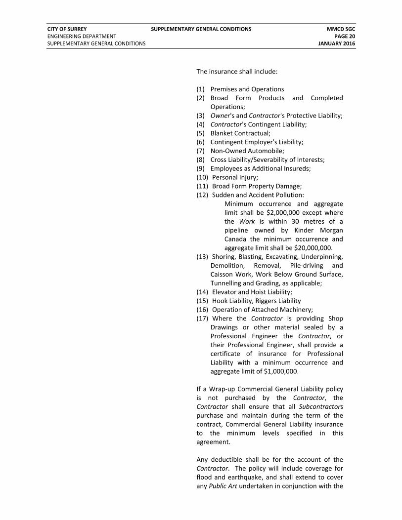
The insurance shall include: (1) Premises and Operations (2) Broad Form Products and Completed
Operations; (3) Owner's and Contractor's Protective Liability; (4) Contractor's Contingent Liability; (5) Blanket Contractual; (6) Contingent Employer's Liability; (7) Non‐Owned Automobile; (8) Cross Liability/Severability of Interests; (9) Employees as Additional Insureds; (10) Personal Injury; (11) Broad Form Property Damage; (12) Sudden and Accident Pollution:
Minimum occurrence and aggregate limit shall be $2,000,000 except where the Work is within 30 metres of a pipeline owned by Kinder Morgan Canada the minimum occurrence and aggregate limit shall be $20,000,000.
(13) Shoring, Blasting, Excavating, Underpinning, Demolition, Removal, Pile‐driving and Caisson Work, Work Below Ground Surface, Tunnelling and Grading, as applicable;
(14) Elevator and Hoist Liability; (15) Hook Liability, Riggers Liability (16) Operation of Attached Machinery; (17) Where the Contractor is providing Shop
Drawings or other material sealed by a Professional Engineer the Contractor, or their Professional Engineer, shall provide a certificate of insurance for Professional Liability with a minimum occurrence and aggregate limit of $1,000,000.
If a Wrap‐up Commercial General Liability policy is not purchased by the Contractor, the Contractor shall ensure that all Subcontractors purchase and maintain during the term of the contract, Commercial General Liability insurance to the minimum levels specified in this agreement. Any deductible shall be for the account of the Contractor. The policy will include coverage for flood and earthquake, and shall extend to cover any Public Art undertaken in conjunction with the

CITY OF SURREY SUPPLEMENTARY GENERAL CONDITIONS MMCD SGC ENGINEERING DEPARTMENT PAGE 21 SUPPLEMENTARY GENERAL CONDITIONS JANUARY 2016
Work, and property at any other location, while in storage, transit and during erection, installation and testing. Coverage shall extend to protect the interest of the Owner, and to the extent that the Owner has an insurable interest, the policy will have the Owner as first loss payee.
Add 24.1.1 (5) The insurance shall include:
(1) a Breach of Conditions clause,
“Notwithstanding anything contained elsewhere in this policy, any breach of a condition of the policy, whether by commission or omission, by one of the parties hereby insured shall not prevent recovery by any other party or all parties hereby insured who are innocent of any such act or breach.”
(2) coverage of resultant damage from error in design that are carried out by the Contractor;
(3) coverage of resultant damage from faulty workmanship; and
(4) coverage of resultant damage from faulty materials.
Add 24.1.1 (6) The Contractor shall provide a certificate of
insurance in the form attached to the Contract Documents. In the event of conflicts between GC 24 and the certificate attached to the Contract Documents, the more stringent requirements shall apply.
27.0 PATENTS AND COPYRIGHTS 27.1 Patent and
Copyright Compliance
Add 27.1.1 The Contractor shall pay all royalties, patents and license fees applicable to any portion of the Work. The Contractor is obligated to ensure that the Work as performed does not breach any copyright, patent or license agreement.
CITY OF SURREY SUPPLEMENTARY GENERAL CONDITIONS MMCD SGC ENGINEERING DEPARTMENT PAGE 22 SUPPLEMENTARY GENERAL CONDITIONS JANUARY 2016
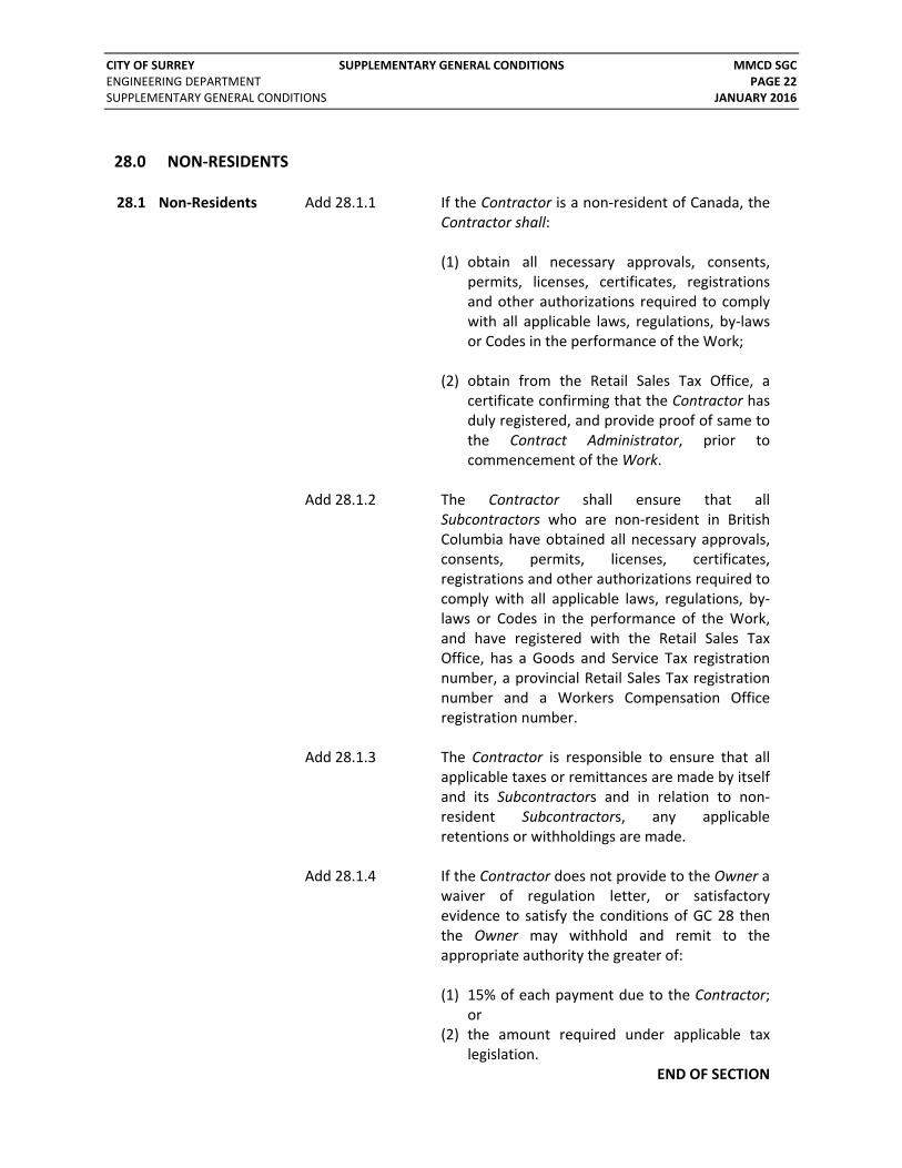
28.0 NON‐RESIDENTS 28.1 Non‐Residents Add 28.1.1 If the Contractor is a non‐resident of Canada, the
Contractor shall: (1) obtain all necessary approvals, consents,
permits, licenses, certificates, registrations and other authorizations required to comply with all applicable laws, regulations, by‐laws or Codes in the performance of the Work;
(2) obtain from the Retail Sales Tax Office, a certificate confirming that the Contractor has duly registered, and provide proof of same to the Contract Administrator, prior to commencement of the Work.
Add 28.1.2 The Contractor shall ensure that all
Subcontractors who are non‐resident in British Columbia have obtained all necessary approvals, consents, permits, licenses, certificates, registrations and other authorizations required to comply with all applicable laws, regulations, by‐laws or Codes in the performance of the Work, and have registered with the Retail Sales Tax Office, has a Goods and Service Tax registration number, a provincial Retail Sales Tax registration number and a Workers Compensation Office registration number.
Add 28.1.3 The Contractor is responsible to ensure that all applicable taxes or remittances are made by itself and its Subcontractors and in relation to non‐resident Subcontractors, any applicable retentions or withholdings are made.
Add 28.1.4 If the Contractor does not provide to the Owner a waiver of regulation letter, or satisfactory evidence to satisfy the conditions of GC 28 then the Owner may withhold and remit to the appropriate authority the greater of: (1) 15% of each payment due to the Contractor;
or (2) the amount required under applicable tax
legislation. END OF SECTION

Engineering Department
Supplementary Master Municipal Construction Documents
SUPPLEMENTARY SPECIFICATIONS
January 2016 (Updated July 01, 2016)
The City of Surrey Supplementary Master Municipal Construction Documents are supplemental to the Master Municipal Construction Document – Platinum Edition (2009) and take precedence over the MMCD General Conditions, Specifications, Standard Detail Drawings and their Amendments.


CITY OF SURREY TABLE OF CONTENTS & CONCORDANCE INDEX MMCD SS ENGINEERING DEPARTMENT PAGE i SUPPLEMENTARY SPECIFICATIONS JANUARY 2016
TABLE OF CONTENTS PAGE
MMCD SECTION 01 33 01 PROJECT RECORD DOCUMENTS ........................................................................... 1 MMCD SECTION 01 34 00S START‐UP TESTING AND COMMISSIONING ............................................................ 3 MMCD SECTION 01 42 00 REFERENCED SPECIFICATIONS ............................................................................. 7 MMCD SECTION 01 55 00 TRAFFIC CONTROL, VEHICLE ACCESS AND PARKING ................................................ 8 MMCD SECTION 01 57 01 ENVIRONMENTAL PROTECTION ......................................................................... 13 MMCD SECTION 01 58 01 PROJECT IDENTIFICATION ................................................................................. 17 MMCD SECTION 01 62 01S LIST OF APPROVED MATERIALS AND PRODUCTS ................................................... 18 MMCD SECTION 03 30 20 CONCRETE WALKS, CURBS AND GUTTERS ........................................................... 30 MMCD SECTION 03 30 53 CAST‐IN‐PLACE CONCRETE ............................................................................... 32 MMCD SECTION 26 56 01 ROADWAY LIGHTING ....................................................................................... 33 MMCD SECTION 31 05 17 AGGREGATES & GRANULAR MATERIALS ............................................................. 35 MMCD SECTION 31 11 41 SHRUB AND TREE PRESERVATION ...................................................................... 36 MMCD SECTION 31 15 60 DUST CONTROL .............................................................................................. 37 MMCD SECTION 31 22 01 SITE GRADING ................................................................................................ 38 MMCD SECTION 31 23 01 EXCAVATING, TRENCHING AND BACKFILLING ....................................................... 39 MMCD SECTION 31 24 13 ROADWAY EXCAVATION, EMBANKMENT AND COMPACTION .................................. 41 MMCD SECTION 32 01 11 PAVEMENT SURFACE CLEANING AND REMOVAL OF PAVEMENT MARKINGS .............. 43 MMCD SECTION 32 01 16.7 COLD MILLING ............................................................................................... 44 MMCD SECTION 32 12 16 HOT‐MIX ASPHALT CONCRETE PAVING .............................................................. 48 MMCD SECTION 32 12 17 SUPERPAVE HOT‐MIX ASPHALT CONCRETE PAVING ............................................. 51 MMCD SECTION 32 14 01 UNIT PAVING ................................................................................................. 54 MMCD SECTION 32 17 23 PAINTED PAVEMENT MARKINGS ....................................................................... 55 MMCD SECTION 32 31 13 CHAIN LINK FENCES AND GATES ........................................................................ 56 MMCD SECTION 32 91 21 TOPSOIL AND FINISH GRADING ......................................................................... 57 MMCD SECTION 32 92 23 SODDING ....................................................................................................... 58 MMCD SECTION 32 93 01 PLANTING OF TREES, SHRUBS AND GROUND COVERS ........................................... 59 MMCD SECTION 33 01 30.1 CCTV INSPECTION OF PIPELINES ....................................................................... 60 MMCD SECTION 33 01 30.2 SEWER CLEANING ........................................................................................... 62 MMCD SECTION 33 11 01 WATERWORKS ............................................................................................... 63 MMCD SECTION 33 30 01 SANITARY SEWERS .......................................................................................... 69 MMCD SECTION 33 34 01 SEWAGE FORCE MAINS .................................................................................... 76 MMCD SECTION 33 40 01 STORM SEWERS ............................................................................................. 79 MMCD SECTION 33 42 13 PIPE CULVERTS ............................................................................................... 81 MMCD SECTION 33 44 01 MANHOLES AND CATCH BASINS ........................................................................ 82 MMCD SECTION 34 41 13 TRAFFIC SIGNALS ............................................................................................ 86


CITY OF SURREY PROJECT RECORD DOCUMENTS MMCD SECTION 01 33 01 ENGINEERING DEPARTMENT SS PAGE 1 SUPPLEMENTARY SPECIFICATIONS JANUARY 2016
MMCD Section 01 33 01 Project Record Documents 1.0 GENERAL
Append to 1.0.1
Operation and Maintenance (O&M) manuals shall be prepared by the Contractor for all projects containing mechanical, electrical or instrumentation materials and equipment, such as but not limited to: pump stations; sewage force mains and siphons; district energy systems; flood boxes, control valves and gates; storm water detention and water quality facilities; reservoirs, pressure reducing stations, wells, flow meters and level meters. O&M manuals shall address all related below‐ground and building interior materials and equipment.
1.4 Format Append to 1.4.2
Binders shall contain DVD's with all documents in PDF format.
Append to 1.4.3
Groupings should be based on MMS Division or Discipline (i.e. HVAC, electrical, instrumentation, etc.).
Append to 1.4.7
Drawings to be included in binders shall consist of Contract Drawings and Shop Drawings.
1.5 Contents, Each Volume
Append to 1.5.3
Part number and serial number shall be included in the list of information for each product.
Append to 1.5.5
The sequence of instructions shall include an Operational Narrative, to be written by the Contract Administrator, that identifies: design objectives and parameters (flows, pressures, velocities); operational and control philosophy, on‐off set points, high and low level alarms, primary, duty and secondary control settings and relationship; and emergency power capacity and fuel capacity.
Append to 1.5.6
Manufacturer's calibration and testing results and certificates for range of parameters and equipment including flow, velocity, pressure, horsepower and air quality emissions.
Append to 1.5.7
Safety Requirements: list of all hazards and safe practices required, including electrical hazards, confined space areas, fall protection, system isolation, de‐pressurising utilities, lockout procedures and required safety training programs.

CITY OF SURREY PROJECT RECORD DOCUMENTS MMCD SECTION 01 33 01 ENGINEERING DEPARTMENT SS PAGE 2 SUPPLEMENTARY SPECIFICATIONS JANUARY 2016
Append to 1.5.8
Parts Inventory: a checklist and tabular summary of all critical parts, and their average delivery times, and recommendation on which spare parts should be kept on hand.
1.6 Record Documents and Samples
Add 1.6.1.10
Shop Drawings that require an Engineer’s Seal are to be sealed by a Professional Engineer registered in the Province of British Columbia.
END OF SECTION

CITY OF SURREY START‐UP, TESTING AND COMMISSIONING MMCD SECTION 01 34 00S ENGINEERING DEPARTMENT SS PAGE 3 SUPPLEMENTARY SPECIFICATIONS JANUARY 2016
MMCD Section 01 34 00S Start‐up Testing and Commissioning 1.0 GENERAL
1.1 Overview .1
This section is applicable to all projects containing mechanical , electrical or instrumentation materials and equipment, such as but not limited to: pump stations; sewage force mains and siphons; district energy systems; flood boxes, control valves and gates; storm water detention and water quality facilities; reservoirs, pressure reducing stations and wells; flow and level meters. The Contractor shall provide, test, commission, and turn over, to the City, a complete operating facility as described in the contract
1.2 Related Work .1
Project Record Documents – Section 01 33 01.
1.3 Scheduling of work
.1
The startup testing and commissioning may need to be or be best scheduled at a time where suitable conditions are present to adequately test the equipment or facility, or at a time when it will disrupt the public or services to the residents the least. The Contractor shall schedule the testing and commissioning to suit these conditions and to cause the least disruption.
1.4 Commissioning
Planning .1
The Contractor shall provide a plan and checklist indicating components and systems to be tested, detailed procedure and schedule for testing and commissioning to the Contract Administrator one month, or sooner, in advance of the commissioning. The checklist shall indicate the following:
1. components and systems to be tested or set 2. test, check or setting result 3. initials of person doing test, check or setting, 4. date and time.
The Contract Administrator and the City will review the plan and checklist and provide any comments they have to the Contractor within one week. The Contractor shall update the plan and checklist based on the Contract Administrator’s and City’s comments as needed. The Contractor shall provide the final testing and commissioning plan and checklist to the Contract Administrator and the City two weeks in advance of the commissioning.

CITY OF SURREY START‐UP, TESTING AND COMMISSIONING MMCD SECTION 01 34 00S ENGINEERING DEPARTMENT SS PAGE 4 SUPPLEMENTARY SPECIFICATIONS JANUARY 2016
The testing and commissioning plan and checklist shall be followed during the testing and commissioning of the equipment. The Contract Administrator may order any changes in testing plan, procedure, operation or schedule at any time before or during testing and commissioning to ensure correct commissioning.
1.8 Payment .1
Payment for all work performed under this Section will be incidental to payment for work described in other Sections unless shown otherwise in the Schedule of Quantities and Prices.
2.0 PRODUCTS
Not Used
3.0 EXECUTION
3.1 Personnel .1 The Contractor shall provide competent, experienced and trained personnel to supervise the installation, inspection, pre‐testing, testing and commissioning of all components and systems installed under this contract. The cost of the personnel supplied by the Contractor, manufacturer and suppliers shall be included in the contract prices. Operation of any part of the existing system shall be performed by the City. Contract Administrator, City and Contractor will be present for the testing and commissioning
3.2 Pre‐testing
.1 The Contractor shall:
.1 Pre‐test all components and systems before start up testing and commissioning where possible, including assistance from the equipment manufacturer’s representatives. This must be co‐ordinated with the Contract Administrator and Owner.
.2 Inspect all materials and components to ensure
that the work is complete and that materials and components are in place and secure.
.3 Ensure that all of the manufacturers and suppliers requirements and recommendations have been complied with.

CITY OF SURREY START‐UP, TESTING AND COMMISSIONING MMCD SECTION 01 34 00S ENGINEERING DEPARTMENT SS PAGE 5 SUPPLEMENTARY SPECIFICATIONS JANUARY 2016
.4 Clean the facility and equipment.
.5 Pre‐test all lights, alarms, locks, and site safety
equipment.
.6 Pre‐test components and systems by themselves and in combination with related components and systems to ensure they are operating properly and comply with specified requirements.
.7 Pre‐test all components over the entire range of operation specified including variations in flow, pressures, speeds and controls/levels.
.8 Pre‐test all malfunctions, alarms, safety devices, interlocks and annunciation by simulation of malfunctions as necessary.
Should tests, checks, inspections indicate defective components or work or performance in variance with specifications the Contractor shall correct the defect or performance.
3.3 Testing and Commissioning
.1 .1 In the presence of the Contract Administrator and the City, the Contractor and the manufacturer’s representatives shall: .1 test all individual components and systems
individually and in combination with related components and systems to ensure they are operating properly and comply with specified requirements.
.2 test and demonstrate all components and systems over the entire range of operation specified including variations in flow, pressures, speeds and controls.
.3 demonstrate all malfunctions, alarms, safety
devices, interlocks and annunciation by simulation of malfunctions as necessary.
.2 Should tests, checks, inspections indicate defective
components or work or performance in variance with specifications the Contractor shall correct the defect or performance.

CITY OF SURREY START‐UP, TESTING AND COMMISSIONING MMCD SECTION 01 34 00S ENGINEERING DEPARTMENT SS PAGE 6 SUPPLEMENTARY SPECIFICATIONS JANUARY 2016
.3 All tests, checks, calibration, adjustments and settings shall be recorded by the Contractor. The record shall be included in the Operation and Maintenance manual.
.4 Provide manufactures certifications as specified before acceptance of the work. The certificates shall be included in the Operation and Maintenance manual.
.5 The Contractor must co‐operate with the City during testing, start‐up and commissioning and during work by the City to install the pertinent equipment for its SCADA system. The SCADA system back panel will be supplied by the City to the Contractor for installation by the Contractor.
.6 Once the testing of components and systems is considered satisfactory by the Contract Administrator the Contractor shall then operate the entire system in the presence of the Contract Administrator and the City.
.7 Upon achieving Substantial Performance and once the operation of the entire system is considered acceptable and operating successfully for at least 48 hours, or longer duration as directed by the Contract Administrator and City, the City will assume responsibility for the operation of the facility at a time acceptable to the City.
.8 Contractor to completely refuel all generators and fuel
storage tanks after testing and prior to transfer to the City.
END OF SECTION

CITY OF SURREY REFERENCED SPECIFICATIONS MMCD SECTION 01 42 00 ENGINEERING DEPARTMENT SS PAGE 7 SUPPLEMENTARY SPECIFICATIONS 2015
MMCD Section 01 42 00 Referenced Specifications
1.0 GENERAL
1.2 Referenced Specifications
Append to 1.2.15.5
CAN / CSA‐A23.5 no longer exists and has been combined into the CSA A3000 Referenced Specification, therefore all references to A23.5 should be changed to CSA A3000.
Add 1.2.15.15
CAN / CSA‐A5 no longer exists and has been combined into the CSA A3000 Referenced Specification, therefore all references to A5 should be changed to CSA A3000.
Add 1.2.15.16
CAN / CSA‐A8 no longer exists and has been combined into the CSA A3000 Referenced Specification, therefore all references to A8 should be changed to CSA A3000.
Add 1.2.9.46
ASTM D6927‐06 Standard Test Method for Marshall Stability and Flow of Asphalt Mixtures.
END OF SECTION

CITY OF SURREY TRAFFIC CONTROL, VEHICLE ACCESS AND PARKING MMCD SECTION 01 55 00 ENGINEERING DEPARTMENT SS PAGE 8 SUPPLEMENTARY SPECIFICATIONS JANUARY 2016
MMCD Section 01 55 00 Traffic Control, Vehicle Access and Parking 1.0 GENERAL
Append to 1.0.1
This section includes requirements for permanent signage.
Add 1.0.6 The Contractor is required to apply for and secure City Road and Right‐of‐Way (CRRP) and Traffic Obstruction (TOP) permits to carry out the Work. Contractor shall comply with the terms and conditions stipulated in these traffic control permits.
Add 1.0.7
For work on Local Roads, except for road closures, detours and locations where traffic impacts will extend back to intersections or Collector or Arterial Roads, permits are required from the City with reference to the BC Traffic Control Manual however a formal Traffic Management Plan (TMP) is not required for submission to the City, unless instructed otherwise.
Add 1.0.8
For work in intersections, on Collector Roads, on Arterial Roads, and where road closures and detours are being proposed, the Contractor shall solely prepare a TMP(s), submit it to the City for acceptance, complete the City’s on‐line process for booking/requesting the road usage, and then implement and maintain the TMP(s). If the Work is located across various locations / sites / roads, each location/road/site will require a unique TMP. The TMP(s) shall include: .1 Name of the: Contractor; Traffic Control Person /
Subcontractor, Owner; Contract Administrator; Contract; Contractor’s Traffic Manager, and the related addresses and contact information.
.2 Be prepared by a qualified Traffic Management Company or Subcontractor, and in accordance with the BC Traffic Control Manual for work on Roadways, as amended.
.3 Be prepared using editable computer program, relatively to scale, and submitted in digital PDF 11x17 format.
.4 Include an accurate road configuration, with road names, north arrow marker, speed limit, and proposed extents or the Work.

CITY OF SURREY TRAFFIC CONTROL, VEHICLE ACCESS AND PARKING MMCD SECTION 01 55 00 ENGINEERING DEPARTMENT SS PAGE 9 SUPPLEMENTARY SPECIFICATIONS JANUARY 2016
.5 Indicate placement marker and distance of signs; sign
images and sign number; delineators, cones, barricades, etc.; position of certified TCP’s and traffic control equipment including FAB’s and HLWD’s
.6 Include Dynamic Message Signs (DMS) and static Message Signs, as directed by the City, for each direction of each project and provide advance notice for full closures.
.7 Identify the number of lanes to be obstructed, along
with taper lengths and widths of lanes.
.8 Identify the impact to: driveways and bus stops; Intersections, turning isles; sidewalks; and bike lanes Include measures to facilitate and maintain access.
.9 Consider project specific restrictions (work hours,
movements, etc.) as outlined in the Contract Documents.
.10 Stipulate that advance notice of construction signs to
be installed at least 5 (five) working days before planned traffic diversion/start of work.
.11 Include map of full detour routes (if applicable),
including the above requirements along each route In the event that excessive traffic delays or unsafe conditions result from implementation of the TMP, the City at its sole discretion may suspend the Work, without schedule extensions nor payment of costs, and the Contractor will be required to modify the TMP.
Contractor responsible to allow sufficient time for TCP review, possible modifications, and preparation of signage when preparing the project schedule. No claims for delays or time extensions will be considered due to failure to obtain an approved TMP. When work is required outside the allowable working/construction hours (i.e. night work), the Contractor shall apply for exemptions to noise by‐laws. The Contractor shall complete all application forms and pay required fees to the City when apply for exemptions

CITY OF SURREY TRAFFIC CONTROL, VEHICLE ACCESS AND PARKING MMCD SECTION 01 55 00 ENGINEERING DEPARTMENT SS PAGE 10 SUPPLEMENTARY SPECIFICATIONS JANUARY 2016
1.3 Temporary
Parking Areas Add 1.3.2
Where it is necessary to temporarily disrupt on‐street parking for construction:
.1 Distribute 72‐hour advance notices to affected
residents and businesses.
.2 Supply and erect temporary no‐parking signs 72 hours in advance and at the same time as issuing notice to residents and businesses. Temporary no‐parking signs shall state hours and dates of when no‐parking is permitted, as well as name and phone number of the Contractor.
.3 Do not impound parked vehicles unless instructed to do so by the RCMP, or if authorized by the City’s Parking Services in conjunction with the City’s By‐law Enforcement.
.4 Vehicles may be towed at Contractor’s risk and expense to a nearby location. Inform registered owner as soon as possible where vehicle has been relocated. Do not charge vehicle recovery or towing fees to vehicle owner.
.5 Prior to use of pay station areas for construction or storage/laydown of equipment and materials, Contractor to get written authorization in advance from the City’s Parking Services and pay/reimburse the City for use of pay station areas.
1.4 Traffic Control Add 1.4.14 Where business driveways are being obstructed for more than one day the Contractor shall post signage to direct business patrons to an alternate entrance.
Add 1.4.15
Do not obstruct any travelled way longer than is absolutely necessary.
Add 1.4.16
Unless expressly stated to in the Contract Documents, temporary road closures will not be permitted.
Add 1.4.17
Where temporary traffic obstructions are permitted by the City, advise the Contract Administrator: .1 At least five (5) Days prior to the date of any
desired closures, and
.2 At least 15 Days prior to the date of any desired full
CITY OF SURREY TRAFFIC CONTROL, VEHICLE ACCESS AND PARKING MMCD SECTION 01 55 00 ENGINEERING DEPARTMENT SS PAGE 11 SUPPLEMENTARY SPECIFICATIONS JANUARY 2016
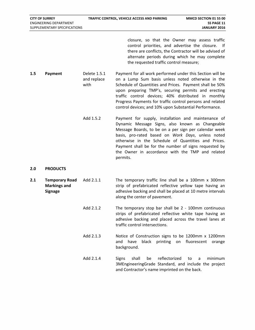
closure, so that the Owner may assess traffic control priorities, and advertise the closure. If there are conflicts, the Contractor will be advised of alternate periods during which he may complete the requested traffic control measure;
1.5 Payment Delete 1.5.1
and replace with
Payment for all work performed under this Section will be on a Lump Sum basis unless noted otherwise in the Schedule of Quantities and Prices. Payment shall be 50% upon preparing TMP’s, securing permits and erecting traffic control devices; 40% distributed in monthly Progress Payments for traffic control persons and related control devices; and 10% upon Substantial Performance.
Add 1.5.2 Payment for supply, installation and maintenance of Dynamic Message Signs, also known as Changeable Message Boards, to be on a per sign per calendar week basis, pro‐rated based on Work Days, unless noted otherwise in the Schedule of Quantities and Prices. Payment shall be for the number of signs requested by the Owner in accordance with the TMP and related permits.
2.0 PRODUCTS
2.1 Temporary Road Markings and Signage
Add 2.1.1
The temporary traffic line shall be a 100mm x 300mm strip of prefabricated reflective yellow tape having an adhesive backing and shall be placed at 10 metre intervals along the center of pavement.
Add 2.1.2
The temporary stop bar shall be 2 ‐ 100mm continuous strips of prefabricated reflective white tape having an adhesive backing and placed across the travel lanes at traffic control intersections.
Add 2.1.3 Notice of Construction signs to be 1200mm x 1200mm and have black printing on fluorescent orange background.
Add 2.1.4 Signs shall be reflectorized to a minimum 3MEngineeringGrade Standard, and include the project and Contractor’s name imprinted on the back.

CITY OF SURREY TRAFFIC CONTROL, VEHICLE ACCESS AND PARKING MMCD SECTION 01 55 00 ENGINEERING DEPARTMENT SS PAGE 12 SUPPLEMENTARY SPECIFICATIONS JANUARY 2016
3.0 EXECUTION
3.1 Temporary Road Markings and Signage
Add 3.1.1
Temporary traffic lines and stop bars shall be placed immediately following laying of the asphalt pavement.
Add 3.1.2
Remove the temporary markings when instructed by the Contract Administrator, immediately before placement of the permanent traffic road markings.
Add 3.1.3 Signs that are not conforming to standards will be removed and replaced with suitable signs at Contractor's cost.
Add 3.1.4 Obtain prior approval from the Contract Administrator on construction speed limit changes.
Add 3.1.5 When the permanent signs are removed during construction, the Contractor shall keep and maintain temporary signs of equal quality in place at all times until permanent replacement signs are reinstated.
3.2 Permanent Signage
Add 3.2.1
Prior to commencement of the Work, prepare and deliver a list of all signs, such as traffic control signs, school signs and playground signs. The City will supply sleeves for traffic sign posts. The Contractor shall arrange to pick up the sleeves from the City. The Contractor is responsible for installing the sleeves and coordinating with the City to install the permanent signage. Contractor shall give the City at least ten (10) days’ notice before requesting the permanent signs be installed. Sign sleeves for bus stops will be supplied by Coast Mountain Bus Company and Contractor to coordinate.
END OF SECTION

CITY OF SURREY ENVIRONMENTAL PROTECTION MMCD SECTION 01 57 01 ENGINEERING DEPARTMENT SS PAGE 13 SUPPLEMENTARY SPECIFICATIONS JANUARY 2016
MMCD Section 01 57 01 Environmental Protection 1.0 GENERAL Delete 1.0.2
and replace with
All Work shall comply with GC 20.4 Environmental Laws, including the City’s Erosion and Sediment Control (ESC) By‐law 2006 No. 16138, and any updates thereto.
Append to
1.0.4 Work in the vicinity of watercourses is subject to restrictions imposed by Federal, Provincial and Municipal Agencies.
1.2 Temporary Erosion and Sediment Controls
Delete 1.2.2.2 and replace with
Do not operate construction equipment in watercourses.
1.4 Environmental Protection
Add 1.4.2.5 To avoid undue impact to nesting birds, vegetation will not be removed or altered during the sensitive breeding period which is generally between March 15 and August 15. If land clearing is necessary within this window, land clearing will proceed only after the Contractor’s qualified Registered Biologist has completed an onsite survey to confirm no impact to nests. If bird nests are found in areas requiring vegetation removal, appropriate buffer zones will be implemented to reduce sensory disturbance until chicks have fledged.
1.6 Payment
Delete 1.6.1 and replace with
Payment for all work performed under this Section will be on a Lump Sum basis unless noted otherwise in the Schedule of Quantities and Prices. Payment shall be 50% upon installing ESC measures; 40% distributed in monthly Progress Payments for maintenance and monitoring related work; and 10% upon Total Performance.
2.0 PRODUCTS
2.1 Contractor Machinery and Equipment
Add 2.1.1 All diesel engine construction equipment and machinery that is 25 horsepower (19 kW) or greater, whether owned or operated by the Contractor or a Subcontractor, shall be registered and in compliance with Metro Vancouver’s Non‐Road Diesel Engine Emissions Regulation Bylaw No 1161, and any updates thereto. Certificates / labels of registration shall be clearly visible on the side or rear of the equipment and machinery.

CITY OF SURREY ENVIRONMENTAL PROTECTION MMCD SECTION 01 57 01 ENGINEERING DEPARTMENT SS PAGE 14 SUPPLEMENTARY SPECIFICATIONS JANUARY 2016
Add 2.1.2 All construction equipment and machinery and generators shall be fitted with standard noise suppression devices. If noise abatement is deemed necessary by the Contract Administrator, mitigation measures, such as time sensitive restrictions or the use of smaller, less disturbing equipment, may be implemented upon the Contractor.
Add 2.1.3 Prior to construction, the Contractor will verify that equipment and machinery used is in good working condition and free of fuel and lubricant leaks. Necessary maintenance oils/lubricants will be stored in a separate, contained lay‐down area, and all maintenance activities will be conducted at least 30 metres away from any watercourse.
2.2 Implementation Add 2.2.1 A fuel spill emergency response kit is to be kept at the place of Work at all times, including at least one for each site/location. The kit should include: material data sheet for hazardous materials being used on site; emergency contact list; absorbent pads; straw bale and poly covers; and floating containment boom for locations adjacent to watercourses.
3.0 EXECUTION
3.1 Implementation Add 3.1.1 The Contractor is responsible for supply, installation, and maintenance of the necessary ESC measures through the entire duration of the Contract, including the clearing and construction stages and through the Maintenance Period, unless noted otherwise in the Contract Documents.
Add 3.1.2 Storm water discharge from the project site must comply
with the City’s ESC By‐law 2006 No. 16138, and any updates thereto.
Add 3.1.3 The Contractor shall use appropriate means to protect the
water quality of all ditches, watercourses and drainage infrastructure.
Add 3.1.4 All ESC measures shall be established in place, and inspected by the Contract Administrator, prior to commencement of any clearing, excavation/stripping and/or placement of fill material. Exclusion zones around watercourses and wetlands shall be flagged to prevent disturbance of vegetated riparian areas by construction machinery, equipment and personnel.

CITY OF SURREY ENVIRONMENTAL PROTECTION MMCD SECTION 01 57 01 ENGINEERING DEPARTMENT SS PAGE 15 SUPPLEMENTARY SPECIFICATIONS JANUARY 2016
Filter fabric, particularly at catch basins and drainage inlets, and silt fences shall be kept clean during construction to ensure adequate drainage is maintained.
3.2 Flow Diversion Add 3.2.1 The Contractor is responsible for management, control and flow diversion, including bypass pumping and water quality treatment, if required, of water from the site, where water includes but not limited to: excavation and trench dewatering, groundwater, surface runoff, sewer and ditch flows, and watercourse flows.
Add 3.2.2 Flow diversion is to be implemented in accordance with the City’s ESC By‐Law, and other Municipal and Agency bylaws and regulations, including discharge quality requirements. If discharge requires third‐party permits (i.e. Metro Vancouver, MOE, FLNRO, DFO, etc.) the Contractor is required to apply and secure these permits, including the associated costs, as part of their Work.
Add 3.2.3 If requested by the Contract Administrator, the Contractor shall prepare and submit a Flow Diversion Plan to the Contract Administrator for review prior to works being completed. The Flow Diversion plan should include: map of the site area complete with excavation and trench limits, location of water sources, proposed pumps/intake piping, proposed flow isolation location and proposed discharge locations; construction methodology; pump, piping and well pointing sizes, including flow rates expected; and ESC measures required for flows. Preparing this plan is considered incident to all other work described in this Section.
Add 3.2.4 If the Work involves construction in and around a watercourse, the Contractor is responsible for site isolation of watercourse flows and fish salvage prior to any dewatering and construction. Related flow diversion during construction shall be completed using gravity piping or pumps equipped with fish screens, in accordance with Ministry of Environment and Department of Fisheries Guidelines.
Add 3.2.5 Sediment laden water shall be properly handled by the Contractor and as a minimum be discharged to a flat, vegetated area or an impervious container, before being further controlled and discharged off site.

CITY OF SURREY ENVIRONMENTAL PROTECTION MMCD SECTION 01 57 01 ENGINEERING DEPARTMENT SS PAGE 16 SUPPLEMENTARY SPECIFICATIONS JANUARY 2016
3.3 Adjustment and Maintenance
Add 3.3.1 The Contractor is responsible for anticipating ESC concerns and adjusting their work plan to mitigate potential risks to ensure all Work is completed in accordance with the Environmental Laws.
Add 3.3.2 For temporary flow diversion pumping systems, which
operate on a 24‐hour basis, Contractor is responsible for operation and maintenance which includes competent staff to operate and maintain the equipment including re‐fuelling the pumps and generators at all times, including night‐time and weekends, and have security personal present to ensure equipment is fully functional.
Add 3.3.3 Deficiencies identified by the Contract Administrator, their site representative and through regular ESC monitoring reports shall be corrected by the Contractor within a reasonable time frame, and no longer than 48 hours. If additional ESC measures are required to correct the deficiencies then these measures are deemed incidental to other work described in this Section and should the deficiencies not be completed within the set timeframe then the Owner reserves the right to have the works corrected and payment will be deducted, at cost plus 10%, from the Contractor’s Progress Certificate with maintenance of the corrected measures to be the Contractor’s responsibility.
Add 3.3.3
Where sediment is observed to have been tracked onto a travelled area, as a result of the Contractor’s Work, then the Contractor must perform sufficient street cleaning within four (4) hours of notification.
Add 3.3.4 Maintenance and revisions to ESC measures are considered incidental to work described herein this Section.
END OF SECTION

CITY OF SURREY PROJECT IDENTIFICATION MMCD SECTION 01 58 01 ENGINEERING DEPARTMENT SS PAGE 17 SUPPLEMENTARY SPECIFICATIONS JANUARY 2016
MMCD Section 01 58 01 Project Identification 1.0 GENERAL 1.2 Temporary
Project Signage
Delete 1.2.1.1 and replace with
1. One week prior to construction, the Contractor shall
install information signs.
2. The Contractor shall maintain the signs for the duration of the contract.
3. The Contractor shall remove the signs after
completion of construction.
Delete 1.2.1.2 and replace with
The City will provide project notification signage and the Contractor shall delivery the signs to site, supply and install the framing, and erect the signage.
Append to 1.2.2.1
Contractor to deliver to businesses and residents copies of letter, provided by the Owner, advising these persons of intended construction activities. The Contractor shall deliver these letters no sooner than ten (10) Days and no later than five (5) Days before the start of construction in the affected area.
END OF SECTION

CITY OF SURREY LIST OF APPROVED MATERIALS AND PRODUCTS MMCD SECTION 01 62 01S ENGINEERING DEPARTMENT SS PAGE 18 SUPPLEMENTARY SPECIFICATIONS JANUARY 2016
MMCD Section 01 62 01S List of Approved Materials and Products This Section identifies the City of Surrey’s List of Approved Products and Materials, and applicable restrictions or specifications, which are to be read in conjunction with, and superseding, products specified within the MMCD Master Specifications. Alternates to the products in this Section require the written approval from the City of Surrey. MMCD Section
Product ApprovedMaterial / Type
ApprovedProduct/Manufacturer
Restrictions/Additional Specifications
26 56 01 ROADWAY LIGHTING
Wire Conductor
Aluminium Alcan Aluminium Nual
SouthwireSimpull
Prysmian Cable
Northern Cable
Copper conductor is acceptable from handhole to fixture in streetlight pole.
Luminaires LED Luminaires LED Roadway lighting NXT series Fixture
American Electric AutoBahn fixture
LED Roadway Lighting NXT series fixture, NXT‐XX‐X‐7‐2ES‐X‐XX‐3‐UL‐S‐2H with adjustable selectable driver. All X's are attributes to be determined by the lighting Consultant to meet City standards for that area. City may permit American Electric AutoBahn fixture Model No. ATB2‐80BLEDEXX‐XXX‐R2‐XX‐P7.
33 11 01 WATERWORKS
2.1.4 Joint Protection
Trenton Tec Tape
Denso Petrolatum Tape
Apply joint protection as per Fraser Health requirement.
2.2.1
Ductile Iron Pipe
Ductile Iron
AWWA C 151, Pressure Class 350.Nitrile gasket required when hydrocarbons encountered in soil.
2.2.2 PVC Pressure Pipe
PVC C900
PVCO C909
Ipex
Royal
Permitted for 150mm – 300mm diameter. Shall be pigmented blue, and shall be bell thickened to ASTM D3139 Clause 6.2. Not permitted on Arterial Roads, nor are they permitted in areas subject to soil liquefaction in seismic events. Nitrile gasket required when hydrocarbons encountered in soil.
July 01/16

CITY OF SURREY LIST OF APPROVED MATERIALS AND PRODUCTS MMCD SECTION 01 62 01S ENGINEERING DEPARTMENT SS PAGE 19 SUPPLEMENTARY SPECIFICATIONS JANUARY 2016
MMCD Section
Product ApprovedMaterial / Type
ApprovedProduct/Manufacturer
Restrictions/Additional Specifications
2.2.3 High Density Polyethylene Pipe
HDPE DR 9 KWH Sclairpipe
WL Plastics
High Performance
HDPE to AWWA C‐906 pipe is permitted for water supply to Agricultural Lands only, and if diameter is 150mm or smaller.
2.2.4 Fittings Ductile Iron
Compact Ductile Iron
Terminal City IW
Sigma Products
Star (C153)
OB Waterworks
Cast Iron fittings are not acceptable
PVC C 907 Injection moulded 100mm – 300mm Diameter
IPEX
Royal
PVC fittings for mainline water mains shall require restrainers to MMCD that do not de‐rate the pressure rating of the pipe material.
PVC C900 Fabricated 150mm – 300mm Diameter
IPEX
Royal
Galaxy Plastic
Pro‐line Fittings
High Deflection coupling by Certain Tee. PVC DR18, C800, Class 150, 5o bend fitting is acceptable.
Bolts, Nuts and Tie Rods
Type 304 Grade A stainless steel required for all hardware.
Couplings and Flange Coupling Adapters
Plain End Dresser 38 or 62
Robar
Smith‐Blair
Romac
EBAA 3800
Ford
Mueller
Type 304 Grade A stainless steel required for all hardware
Restrained Flange Adaptors
Romac RFCA
Uniflange RFAD
EBAA 2100
Type 304 Grade A stainless steel required for all hardware
Repair Clamps Robar
Romac
Mueller
Canpac
Couplers shall have appropriate adaptor gaskets to suit OD of pipe material(s) being coupled.
Joint Restraint Devices
Ductile Iron Mains UniFlange Series 1400
EBBA Iron
Joint restraints shall have pressure rating equal to the mainline pipe. Type 304 Grade A stainless steel required for all hardware
PVC / PVCO Mains
EBAA Series 1900
Uniflange Series 1309, 1399, 1500
JCM Series 610
Restraints for PVC/PVCO shall be approved by pipe manufacturer. Type 304 Grade A stainless steel required for all hardware
Integral Joint Restraints
Terra Brute
Cobra Lock
July 01/16
July 01/16
July 01/16
July 01/16
July 01/16
July 01/16
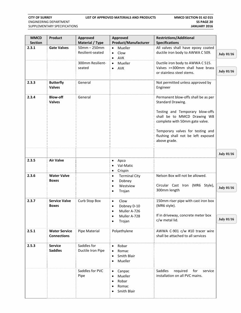
CITY OF SURREY LIST OF APPROVED MATERIALS AND PRODUCTS MMCD SECTION 01 62 01S ENGINEERING DEPARTMENT SS PAGE 20 SUPPLEMENTARY SPECIFICATIONS JANUARY 2016
MMCD Section
Product Approved Material / Type
ApprovedProduct/Manufacturer
Restrictions/Additional Specifications
2.3.1 Gate Valves 50mm – 250mm Resilient‐seated
Mueller
Clow
AVK
All valves shall have epoxy coated ductile iron body to AWWA C 509.
300mm Resilient‐seated
Mueller
AVK
Ductile iron body to AWWA C 515.Valves >=300mm shall have brass or stainless steel stems.
2.3.3 Butterfly Valves
General Not permitted unless approved by Engineer
2.3.4 Blow‐off Valves
General Permanent blow‐offs shall be as per Standard Drawing. Testing and Temporary blow‐offs shall be to MMCD Drawing W8 complete with 50mm gate valve. Temporary valves for testing and flushing shall not be left exposed above grade.
2.3.5 Air Valve Apco
Val‐Matic
Crispin
2.3.6 Water Valve Boxes
Terminal City
Dobney
Westview
Trojan
Nelson Box will not be allowed. Circular Cast Iron (MR6 Style), 300mm length
2.3.7 Service Valve Boxes
Curb Stop Box Clow
Dobney D‐10
Muller A‐726
Muller A‐728
Trojan
150mm riser pipe with cast iron box(MR6 style). If in driveway, concrete meter box c/w metal lid.
2.5.1 Water Service Connections
Pipe Material Polyethylene AWWA C‐901 c/w #10 tracer wire shall be attached to all services
2.5.3 Service Saddles
Saddles for Ductile Iron Pipe
Robar
Romac
Smith Blair
Mueller
Saddles for PVC Pipe
Canpac
Mueller
Robar
Romac
Smith Blair
Saddles required for service installation on all PVC mains.
July 01/16
July 01/16
July 01/16
July 01/16
July 01/16

CITY OF SURREY LIST OF APPROVED MATERIALS AND PRODUCTS MMCD SECTION 01 62 01S ENGINEERING DEPARTMENT SS PAGE 21 SUPPLEMENTARY SPECIFICATIONS JANUARY 2016
MMCD Section
Product Approved Material / Type
ApprovedProduct/Manufacturer
Restrictions/Additional Specifications
2.6 Hydrants Terminal City C71P
Canada Valve “Century”
Clow M93 Brigadier
AVK 2780
Ductile iron boot shall be installed. Refer to SS for Paint Colours and requirements
2.7 Underground Service Line Valves and Fittings
Corporation Stop Cambridge
Ford
Mueller
Shall be full‐port ball valve up to 38mm only. Use mainline ball valve for sizes 50mm and larger.
Curb Stop Cambridge
Ford
Mueller
Shall be full‐port ball valve to 38mm with 900 turn stop. Use gate and check valve, near property line, for sizes 50mm and larger
2.10 Casing Spacers Uniflange
Calpico
Raci
Shall be fabricated cast iron or high density polyethylene insulating spacers designed to centre main in the carrier pipe.
33 30 01 SANITARY SEWERS
2.1 Concrete Pipe
Non‐reinforced and Reinforced Concrete
Langley Concrete
Ocean Pipe
Manufacturers to be PPP or Q‐Cast Certified Concrete sewers 200mm to 750mm requires prior approval from the Engineer. Sewers 900mm in diameter and larger shall have factory PVC/HDPE interior liner (T‐Lok or Agru)
2.2 Plastic Pipe, Mainline Smooth Profile
PVC SDR 35 IPEX
Royal
JM Eagle
Northern
Maximum diameter of 750mm Recycled PVC (EnviroTite SDR) is not permitted. No repairs from inside pipe.
July 01/16
July 01/16
July 01/16

CITY OF SURREY LIST OF APPROVED MATERIALS AND PRODUCTS MMCD SECTION 01 62 01S ENGINEERING DEPARTMENT SS PAGE 22 SUPPLEMENTARY SPECIFICATIONS JANUARY 2016
MMCD Section
Product Approved Material / Type
ApprovedProduct/Manufacturer
Restrictions/Additional Specifications
2.2 (cont’d)
High Density Polyethylene Pipe
HDPE smooth wall pipe with fusion welded joints
KWH Sclairpipe
WL Plastics
High Performance
Only to be used at location approved by the City Shall be DR 21 or thicker
2.3 Service Connections
PVC‐SDR 28 IPEX
Royal
JM Eagle
Northern
Minimum size shall be 100mm.
Tees and Wyes PVC‐SDR 28 IPEX
Royal
JM Eagle
Northern
Manufactured wye fitting shall be used for all connections on new mains.
Insertable Tee Inserta Tee
Insertable tee only permitted for connections to PVC and Concrete mains which are 200mm mains or larger. Connections to 150mm diameter mains, AC and VC mains, require manufactured wye.
Saddle Robar 3506
Romac CB
Applicable for connections to AC and Vitrified Clay mainlines. Stainless steel straps required.
Inspection Chamber
Inspection Chamber
Pro‐Line
Royal
Galaxy Plastics
IC to have locking lid c/w gasket
Cover: Cast Iron MR Style
TR 10C
Dobney MR 10‐18B
TC 10C
Shall be used in all travelled areas, and when I.C. within 2.0m of travelled areas.
Inspection Chamber Back‐flow Check Valve
Pro‐line Fittings
Royal
Galaxy Plastics
Comply with CSA/CAN3 B70‐M86.
July 01/16
July 01/16
July 01/16

CITY OF SURREY LIST OF APPROVED MATERIALS AND PRODUCTS MMCD SECTION 01 62 01S ENGINEERING DEPARTMENT SS PAGE 23 SUPPLEMENTARY SPECIFICATIONS JANUARY 2016
MMCD Section
Product Approved Material / Type
ApprovedProduct/Manufacturer
Restrictions/Additional Specifications
33 34 01 SEWAGE FORCE MAINS
2.2.1 Ductile Iron Pipe
General Not permitted for sewage forcemains
2.2.2 PVC Pressure Pipe
PVC C900
PVCO C909
Ipex
Royal
Permitted for 150mm – 300mm diameter, DR18 or thicker. Shall be pigmented blue, and shall be bell thickened to ASTM D3139 Clause 6.2. Not permitted on Arterial Roads, nor are they permitted in areas subject to soil liquefaction in seismic events.
2.2.4 High Density Polyethylene Pipe
HDPE DR 17 (or thicker)
KWH Sclairpipe
WL Plastics
High Performance
HDPE comply with AWWA C906 for pipe 100mm diameter and larger. Outside diameter (OD) to iron pipe size (IPS) dimensions.
2.2.5 Fittings:
Saddle Friatec VA
Corix Flo‐Control (75‐150mm)
Electrofusion Saddle Service for HDPE
Bolts, Nuts and Tie Rods
Type 304 Grade A stainless steel required for all hardware.
2.2.8 Low‐pressure Sewage Force mains
HDPE DR 13.5 (or thicker)
KWH Sclairpipe
WL Plastics
High Performance
HDPE comply with AWWA C901 for pipes 75mm diameter and smaller and AWWA C906 for pipe 100mm diameter and larger. Outside diameter (OD) to iron pipe size (IPS) dimensions.
PVC C900
PVCO C909
Ipex
Royal
Permitted for 150mm – 300mm diameter, DR18 or thicker. Shall be pigmented blue, and shall be bell thickened to ASTM D3139 Clause 6.2. Not permitted on Arterial Roads, nor in areas subject to soil liquefaction in seismic events.
July 01/16
July 01/16

CITY OF SURREY LIST OF APPROVED MATERIALS AND PRODUCTS MMCD SECTION 01 62 01S ENGINEERING DEPARTMENT SS PAGE 24 SUPPLEMENTARY SPECIFICATIONS JANUARY 2016
MMCD Section
Product Approved Material / Type
ApprovedProduct/Manufacturer
Restrictions/Additional Specifications
2.3.2 Gate Valves 50mm – 250mm Resilient‐seated
Mueller
Clow
AVK
All valves shall have epoxy coated ductile iron body to AWWA C 509.
>= 300mm Resilient‐seated
Mueller
AVK
Ductile iron body to AWWA C 515.Valves >300mm shall have brass or stainless steel stems.
2.3.4 Air Valves Apco
ARI
Val‐Matic
25mm valves to be brass
2.3.6 Plug Valves
APCO series 500 resilient‐seated
Milliken Millcentric
Valmatic Eccentric
All Plug Valves to be Full Port. Refer to SS Section 33 34 01, 2.6
2.3.7 Ball Valves Unifid Alloys All Ball Valves to be Full Port. 50mm and smaller to be brass, larger to be stainless steel and flanged.
2.3.8 Check Valves
Ball Check –Cast/Ductile Iron
Danfoss 408/408FB Plastic check valves not permitted.
2.5 Low Pressure Sewage Pumps
Grinder Pumps ABS
Barnes
Environment One
Hydromatic
ITT Flytt / Xylem
Myers
Zoeller
Refer to Design Criteria Manual for more specifications.
33 40 01 STORM SEWERS
2.1 Concrete Pipe Non‐reinforced and Reinforced Concrete
Langley Concrete
Ocean Pipe
Manufacturers to be PPP or Q‐Cast Certified Not permitted in Lowland areas (below 7.0m elev.)
2.2 PVC Pipe, Mainline Smooth Wall
PVC SDR 35 IPEX
Royal
JM Eagle
Northern
Maximum diameter of 750mm Recycled PVC (EnviroTite SDR) not permitted. No repairs from inside pipe.
July 01/16
July 01/16
July 01/16
July 01/16

CITY OF SURREY LIST OF APPROVED MATERIALS AND PRODUCTS MMCD SECTION 01 62 01S ENGINEERING DEPARTMENT SS PAGE 25 SUPPLEMENTARY SPECIFICATIONS JANUARY 2016
MMCD Section
Product Approved Material / Type
ApprovedProduct/Manufacturer
Restrictions/Additional Specifications
2.3 PVC Pipe, Mainline Profile
IPEX
Royal (Korflo)
Only permitted in Lowland areas (below 7.0m elev.) Only permitted up to 675mm in diameter. Spiral ribbed pipe is not permitted. IPEX Ultra‐Rib not permitted. No repairs from inside pipe.
2.4 HDPE Pipe, Mainline Open Profile
HDPE smooth wall pipe with fusion welded joints
KWH Sclairpipe
WL Plastics
High Performance
Only permitted in Lowland areas (below 7.0m elev.) unless approved otherwise by the City Shall be DR 21 or thicker
2.5 Spiral Rib Steel Pipe
Not permitted Steel and CSP pipe is not permitted for storm sewers.
2.6 Service Connections
PVC‐SDR 28 IPEX
Royal
JM Eagle
Northern
Minimum size shall be 150mm.
Tees and Wyes PVC‐SDR 28 IPEX
Royal
JM Eagle
Northern
Manufactured wye fitting shall be used for all connections on new mains.
Insertable Tee Inserta Tee
Insertable tee only permitted for connections to PVC and Concrete mains which are 200mm mains or larger. Connections to 150mm diameter mains, AC and VC mains, require manufactured wye.
Saddle Robar 3506
Romac CB
Applicable for connections to AC and Vitrified Clay mainlines. Stainless steel straps required.
July 01/16
July 01/16

CITY OF SURREY LIST OF APPROVED MATERIALS AND PRODUCTS MMCD SECTION 01 62 01S ENGINEERING DEPARTMENT SS PAGE 26 SUPPLEMENTARY SPECIFICATIONS JANUARY 2016
MMCD Section
Product Approved Material / Type
ApprovedProduct/Manufacturer
Restrictions/Additional Specifications
Inspection Chamber
Inspection Chamber
Pro‐Line
Royal
Galaxy Plastics
IC to have locking lid c/w gasket
Cover: Cast Iron MR Style
TR 10C
Dobney MR 10‐18B
TC 10C
Shall be used in all travelled areas, and when I.C. within 2.0m of travelled areas.
Inspection Chamber Back‐flow Check Valve
Pro‐line
Royal
Galaxy Plastics
Comply with CSA/CAN3 B70‐M86.
2.11 Polypropylene Pipe, Mainline Open Profile
ADS Santite HP Only permitted in Lowland areas (below 7.0m elev.) Service connections on new Open Profile HDPE / Polypropylene mains shall be injection moulded PVC manufactured wyes for mains < 300mm.
33 42 13 PIPE CULVERTS
2.1 Corrugated Steel Pipe
Armtec
Canada Culvert
Atlantic Industries
Only permitted in Lowland areas (below 7.0m elev.) Shall be Aluminized II coating. Requires prior approval from the Engineer.
2.2 Concrete Pipe Non‐Reinforced and Reinforced Concrete
Langley Concrete
Ocean Pipe
Not permitted in Lowland areas (below 7.0m elev.) Manufacturers to be PPP or Q‐Cast Certified.
2.3 PVC Pipe, Mainline Smooth Wall
PVC‐SDR 35 IPEX
Royal
2.4 PVC Pipe Profile, Mainline
IPEX
Royal (Korflow)
Only permitted in Lowland areas (below 7.0m elev.) Only permitted up to 675mm in diameter. Spiral ribbed pipe is not permitted. IPEX Ultra‐Rib not permitted.
July 01/16
July 01/16
July 01/16
July 01/16
July 01/16
July 01/16
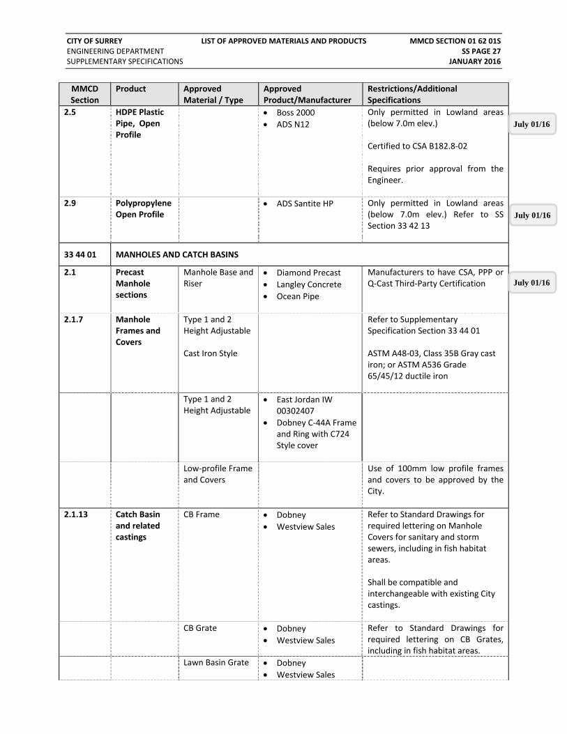
CITY OF SURREY LIST OF APPROVED MATERIALS AND PRODUCTS MMCD SECTION 01 62 01S ENGINEERING DEPARTMENT SS PAGE 27 SUPPLEMENTARY SPECIFICATIONS JANUARY 2016
MMCD Section
Product Approved Material / Type
ApprovedProduct/Manufacturer
Restrictions/Additional Specifications
2.5 HDPE Plastic Pipe, Open Profile
Boss 2000
ADS N12
Only permitted in Lowland areas (below 7.0m elev.) Certified to CSA B182.8‐02 Requires prior approval from the Engineer.
2.9 Polypropylene Open Profile
ADS Santite HP Only permitted in Lowland areas (below 7.0m elev.) Refer to SS Section 33 42 13
33 44 01 MANHOLES AND CATCH BASINS
2.1 Precast Manhole sections
Manhole Base and Riser
Diamond Precast
Langley Concrete
Ocean Pipe
Manufacturers to have CSA, PPP or Q‐Cast Third‐Party Certification
2.1.7 Manhole Frames and Covers
Type 1 and 2 Height Adjustable Cast Iron Style
Refer to Supplementary Specification Section 33 44 01 ASTM A48‐03, Class 35B Gray cast iron; or ASTM A536 Grade 65/45/12 ductile iron
Type 1 and 2 Height Adjustable
East Jordan IW 00302407
Dobney C‐44A Frame and Ring with C724 Style cover
Low‐profile Frame and Covers
Use of 100mm low profile frames and covers to be approved by the City.
2.1.13 Catch Basin and related castings
CB Frame Dobney
Westview Sales
Refer to Standard Drawings for required lettering on Manhole Covers for sanitary and storm sewers, including in fish habitat areas. Shall be compatible and interchangeable with existing City castings.
CB Grate Dobney
Westview Sales
Refer to Standard Drawings for required lettering on CB Grates, including in fish habitat areas.
Lawn Basin Grate Dobney
Westview Sales
July 01/16
July 01/16
July 01/16

CITY OF SURREY LIST OF APPROVED MATERIALS AND PRODUCTS MMCD SECTION 01 62 01S ENGINEERING DEPARTMENT SS PAGE 28 SUPPLEMENTARY SPECIFICATIONS JANUARY 2016
MMCD Section
Product Approved Material / Type
ApprovedProduct/Manufacturer
Restrictions/Additional Specifications
2.1.16 Tapered Adjusting Rings
Concrete
Ductile Iron
EPP
HDPE
Ipex
Dobney
ARPRO
2.24 Sealant Sealant to be ASTM D 1850
X‐Seal from SealGuard Inc.
33 41 13 TRAFFIC SIGNALS
2.5
Concrete Junction Boxes
Armtec Labelled “ELEC”
2.6
Poles and Anchor Bolts
Poles, Arms,Service Base
Nova Pole
West Coast Engineering
M.O.T.I/MMCD Galvanized and powder coated
2.7 Conductors and Cables
Pre‐Emption Cable
GTT Model 138
Radio Cable Cat 6 Ethernet cable
Outdoor rated
2.11 Service Panels Service Panel
Westcoast Electric
Valid Manufacturing
Stainless Steel or Powder Coated Aluminum – See Std Drawings
2.16. Traffic and Pedestrian Signals
Signal Heads
Econolite
Eagle
M.O.T.I/MMCD – Aluminum Housing
Pedestrian Heads McCain
Eagle
Current ITE Specifications –Aluminium Housing
2.17. LED Signal Modules
LED Vehicle Display
Dialight
Leotek
M.O.T.ICurrent ITE Specifications
LED Pedestrian Displays
Dialight
Leotek
Current ITE SpecificationsC/W countdown timer
2.19 Sign Mounting Hardware
Overhead adjustable Bracket
Pelco Astro‐brac
Side mount Brackets
Greenlite Traffic M.O.T.I – GEL 189
2.21. Pedestrian / Cyclist Pushbuttons
Push Button Sign Unit
Polara Navigator APS EZ 2 wire C/W Central Control and Ped Station Monitor Unit.
2.28 Uninterrupted Power Supply
UPS Alpha FXM Series

CITY OF SURREY LIST OF APPROVED MATERIALS AND PRODUCTS MMCD SECTION 01 62 01S ENGINEERING DEPARTMENT SS PAGE 29 SUPPLEMENTARY SPECIFICATIONS JANUARY 2016
MMCD Section
Product Approved Material / Type
ApprovedProduct/Manufacturer
Restrictions/Additional Specifications
2.32 Extruded Aluminium Signs
Streetname Sign Mount
Fortran Can‐Brac assembly
Special Crosswalk Controller
Novax PXO‐II
Fire Hall Signal Controller
Novax ELA515
END OF SECTION

CITY OF SURREY CONCRETE WALKS, CURBS AND GUTTERS MMCD SECTION 03 30 20 ENGINEERING DEPARTMENT SS PAGE 30 SUPPLEMENTARY SPECIFICATIONS JANUARY 2016
MMCD Section 03 30 20 Concrete Walks, Curbs and Gutters 1.0 GENERAL
1.4 Measurement and Payment
Append to 1.4.3 Payment shall also include joint and surface finishing. Curb within the area ramp or driveway crossing is considered regular curb for the purpose of payment.
Append to 1.4.5 Payment will be on actual area placed, unless noted otherwise in the Schedule of Quantities and Prices.
Delete 1.4.6 and replace with
Concrete driveway crossing will be based on actual area placed for different types of finishes and thickness. Payment shall be for those driveways noted on the Contract Drawings, and include grading of base gravels, supply and placement of concrete and surface finishing.
Append to 1.4.8 Adjustment shall include: removal of existing frame and cover; cleaning; re‐set to meet new grade, profile and cross fall; replace grade rings.
2.0 PRODUCTS
2.1 Materials
Amend 2.1.5.1
Minimum cement content should be 335 kg/m3.
Add 2.1.5.3 Exposed Aggregate Concrete shall be 32MPa 9.5mm Chilliwack Exposed mix.
Add 2.1.7 1. Colored Patterned Surface for median infill, splash strips, and maintenance vehicle parking pads shall be: 100mm thick stamped colored concrete splash strips or median infill except in maintenance vehicle parking area where concrete shall be 120mm thick.
2. Concrete color to be Brick Red or equivalent using Davis Pigment # 160 at rate of 30 pounds per cubic meter. Stamped concrete pattern shall be running bond pattern.
All coloured concrete to be sealed with clear/translucent sealer after installation and surface is swept clean.
2.2 Curbs & Gutters
Add 2.2.1
On all roads with bike lanes, curb/gutter/catch basins adjacent to the bike lane shall be bike friendly as per Standard Drawing.
Add 2.2.2
All references to concrete barrier curb shall be the narrow base barrier curb as per the Standard Detail Drawing C4, unless approved otherwise by the City.
July 01/16
CITY OF SURREY CONCRETE WALKS, CURBS AND GUTTERS MMCD SECTION 03 30 20 ENGINEERING DEPARTMENT SS PAGE 31 SUPPLEMENTARY SPECIFICATIONS JANUARY 2016
3.0 EXECUTION
3.13 Special Effects
Add 3.13.3
Exposed aggregate concrete shall be placed in similar fashion as regular concrete finish, except:
.1 Concrete surface shall be washed to expose the aggregates underneath after concrete has been set.
.2 During the wash, all washed water shall be collected and disposed in accordance with the local Best Management Practices.
.3 Disposing the washed water into the storm or sanitary system will not be permitted.
.4 In instances where disposal offsite is not achievable, with the approval of the Contract Administrator, the Contractor may install an onsite collection pond to store and dissipate the washed water through infiltration.
END OF SECTION

CITY OF SURREY CAST‐IN‐PLACE CONCRETE MMCD SECTION 03 30 53 ENGINEERING DEPARTMENT SS PAGE 32 SUPPLEMENTARY SPECIFICATIONS JANUARY 2016
MMCD Section 03 30 53 Cast‐in‐Place Concrete 1.0 GENERAL
1.4 Measurement and Payment
Append to 1.5.5 Payment will be on an individual basis for the complete headwall or other structure being constructed.
3.0 EXECUTION
3.5 Acceptance
Add 3.5.1
Concrete shall develop a minimum compressive strength of 32 MPa at 28 days based on standard cylinder test, performed in accordance with CSA A23.2‐9C, based on concrete cylinders collected on the day of placement.
Add 3.5.2
One strength test (3 specimen cylinders) shall be made for each 100 square metres of concrete work. In no case, however, shall there be less than one strength test for concrete placed in one day. One cylinder shall be tested at 7 days, 2 cylinders shall be tested at 28 days.
Add 3.5.3
The core test shall be performed in accordance with CSA 23.2‐14C. The compressive strength of the concrete, based on core tests, shall be interpreted from CSA A23.1‐94.
Add 3.5.4
In the event that the cylinders, tested at 28 days, fail to achieve the specified 32 MPa, the Contractor shall, upon notification, obtain cores for further testing. The cores are to be drilled from the portions of the structure in question and tested prior to day 38.
Add 3.5.5
Concrete not meeting the minimum compressive strength criteria shall be rejected and must be removed and replaced at the Contractor’s expense.
END OF SECTION

CITY OF SURREY ROADWAY LIGHTING MMCD SECTION 26 56 01 ENGINEERING DEPARTMENT SS PAGE 33 SUPPLEMENTARY SPECIFICATIONS JANUARY 2016
MMCD Section 26 56 01 Roadway Lighting
1.0 GENERAL
1.4 Electrical Energy Supply
Add 1.4.4
The Contractor shall coil and tape conductors out of weather head. Utility company shall complete electrical service connections.
2.0 PRODUCTS
2.1 General
Append to 2.1.2
All products must bear evidence of either a mark or a label of a certification agency accredited by the Standards Council of Canada or an approved label issued by the BC Safety Authority.
Replace 2.1.3
All products shall be in accordance with Section 01 62 01S.
2.4 Plastic Junction Boxes
Append to 2.4.1 Lids for plastic junction boxes to be galvanized.
2.5 Concrete Junction Boxes
Delete 2.5.1 and replace with
Refer to Drawing SSD‐R.E.6 and R.E.7 for concrete junction box details.
2.7 Poles and Anchor Bolts
Append to 2.7.1 Roadway Lighting poles shall be Type S or L Shafts as defined on the Contract Drawings. Pole specifications vary by neighbourhoods and the latest specifications are available from the City’s Engineering Traffic Operations Section.
2.8 Conductors and Cables
Add 2.8.5
Roadway Lighting Feeder Conductors: 600V, conductor size (AWG) as noted on Contract Drawings, stranded aluminum type with RW90 polyethylene insulation, to conform to CSA C22.2 No. 38, 90°C, and color coded as per CEC. All new roadway lighting systems shall be constructed with underground aluminum conductors. System bonding conductors shall be aluminum. Service Panel grounding conductor shall be copper. Pole raceway conductors shall be RW90 stranded copper.
2.10 Conductor Connectors
Delete 2.10.1 and replace with
Compression Type: Connectors shall accommodate combinations of aluminum to copper, and aluminum to aluminum conductors. Size to suit conductor gauge and number of conductors.

CITY OF SURREY ROADWAY LIGHTING MMCD SECTION 26 56 01 ENGINEERING DEPARTMENT SS PAGE 34 SUPPLEMENTARY SPECIFICATIONS JANUARY 2016
2.14 Luminaires
Delete 2.14.1 and replace with
All luminaires shall be LED.
Delete 2.14.2 and replace with
All luminaires shall be LED.
3.0 EXECUTION
3.1 General Add 3.1.5 When tying into or upgrading an existing installation, maintain the existing lighting system operation during the hours of darkness.
3.5 Underground Conduits
Delete 3.5.2 and replace with
Minimum cover over conduits to be 600mm in boulevard areas and 900mm in travelled areas.
Add 3.5.6
Before pulling conductor cable/wire into a run of conduit, the conduit shall be blown out with compressed air, and pull string installed with caps at each end. Conductors shall be pulled in slowly by hand or hand winch, in order to keep close control on pulling tension and prevent cutting the conduit at bends.
3.8 Wiring Delete 3.8.3 and replace with
See Drawing SSD‐R.E.13 for splice details. Delete reference to solderless type connectors as connectors shall be compression type. Use tool recommended by the connector supplier to make splices. Connectors shall be prefilled with an oxide‐inhibiting joint compound.
Delete 3.8.8 and replace with
Secure conductor splices with compression type connectors. Install using manufacturer recognized mechanical or hydraulic compression tools and matching die set. An oxide‐inhibiting joint compound shall be used for terminating or splicing all aluminum conductors.
3.10 Luminaires and Photocells
Add 3.10.4 NEMA wattage label shall be visible at the bottom of the luminaire on all fixtures. Place label on the underside of the luminaire for cobra heads and on the neck or top of pole for post tops.
END OF SECTION

CITY OF SURREY AGGREGATES AND GRANULAR MATERIALS MMCD SECTION 31 05 17 ENGINEERING DEPARTMENT SS PAGE 35 SUPPLEMENTARY SPECIFICATIONS JANUARY 2016
MMCD Section 31 05 17 Aggregates & Granular Materials 1.0 GENERAL
1.5 Inspection and Testing
Add to 1.5.2 Sieve analysis and proctors are required for each type of material to be used prior to the commencement of Work and every 1,000 tonnes during the Work.
2.0 PRODUCTS
2.7 Granular Pipe Bedding and Surround Material
Change 2.7 Delete “Recycled concrete free from contaminated and other extraneous material, conforming to the Type 1 gradations, may be used as pipe bedding and surround material.
2.10 Granular Base
Delete 2.10.2 Delete the use of Type 2 – 19mm crushed gravel.
END OF SECTION

CITY OF SURREY SHRUB AND TREE PRESERVATION MMCD SECTION 31 11 41 ENGINEERING DEPARTMENT SS PAGE 36 SUPPLEMENTARY SPECIFICATIONS JANUARY 2016
MMCD Section 31 11 41 Shrub and Tree Preservation 1.0 GENERAL
1.3 Measurement and Payment
Delete 1.3.1 and replace with
Payment for all shrub and tree preservation, including tree protection fencing, grading, exposing root zone and hand excavation, and works deemed necessary by a certified arborist or the Contract Administrator, is applicable to all work performed under this Section, and incidental to payment for work described in other Sections unless shown otherwise in the Schedule of Quantities and Prices.
END OF SECTION

CITY OF SURREY DUST CONTROL MMCD SECTION 31 15 60 ENGINEERING DEPARTMENT SS PAGE 37 SUPPLEMENTARY SPECIFICATIONS JANUARY 2016
MMCD Section 31 15 60 Dust Control 3.0 EXECUTION
3.1 Application Append to 3.1.1
Control of dust and sediment is critical. The Contractor will regularly scrape, sweep and clean the roads. The sites must be maintained in a professional manner to ensure that the works does not adversely affect the residents in the area. Dust and sediment build‐up on adjacent surrounding roads or grounds is not permitted and must be immediately removed by the Contractor.
Append to 3.1.3
Aqueous chloride and magnesium cannot be used for work areas within 100m of a watercourse, and work areas that are draining to a watercourse.
Add 3.1.5 The Contract Administrator may request additional street cleaning which shall be promptly undertaken at the Contractor’s expense.
Add 3.1.6 If the Contractor fails to maintain dust and sediment
control the City can carry out the dust and sediment control as needed and costs will be charged against the Contractor.
END OF SECTION
July 01/16

CITY OF SURREY SITE GRADING MMCD SECTION 31 22 01 ENGINEERING DEPARTMENT SS PAGE 38 SUPPLEMENTARY SPECIFICATIONS JANUARY 2016
MMCD Section 31 22 01 Site Grading 1.0 GENERAL
1.4 Measurement and Payment
Delete 1.4.1 and replace with
No separate payment will be made for topsoil stripping, unless noted otherwise in the Schedule of Quantities and Prices, as payment for this work shall be included in rough site grading and common excavation.
Append to 1.4.2
Rough site grading and redistribution of excavated materials to design elevations and grades will be paid on a volumetric basis, measured in cubic meters based on before and after surveyed cross sections measured at a maximum 20 meter interval.
3.0 EXECUTION
3.2 Grading Delete 3.2.2 and replace with
Works shall be carried out in accordance with Section 31 23 01 ‐ Excavating, Trenching and Backfilling ‐ 3.5.4, except Provincial Highways where the compaction shall be 95% Modified Proctor density.
3.3 Tolerances Delete 3.3.1
and replace with
Accuracy of subgrade elevations to be within tolerances shown in Table 2.
Table 2: Tolerances for Subgrade where Growing Medium (Topsoil) to be Placed Over Subgrade
Intended Growing Medium Depth
Tolerance
0 – 150mm 151 – 300mm 301 – 600mm
25mm +/‐ 25mm +/‐ 50mm +/‐
END OF SECTION

CITY OF SURREY EXCAVATING, TRENCHING AND BACKFILLING MMCD SECTION 31 23 01 ENGINEERING DEPARTMENT SS PAGE 39 SUPPLEMENTARY SPECIFICATIONS JANUARY 2016
MMCD Section 31 23 01 Excavating, Trenching and Backfilling 1.0 GENERAL
1.3 Definitions Append to 1.3.4
Removals shall also include asphalt; concrete; driveways; street lights and traffic signals and their bases; electrical and communication conduits and vaults; fences; handrails; and similar works.
1.10 Measurement and Payment
Append to 1.10.1
Payment for works in this Section shall include excavation, shoring, trench and site dewatering, hauling and disposal, of surplus soil.
Append to
1.10.7 Cleaning and deepening of existing channel or ditch shall be paid on a lineal metre basis as measured along centerline, unless noted otherwise in the Schedule of Quantities and Prices.
Append to 1.10.8
Payment for boulevard swale shall be measured on a lineal metre along centerline, unless noted otherwise in the Schedule of Quantities and Prices.
1.11 Inspection and Testing
Add 1.11.2 For items that are measured by weight, the Contractor shall: .1 Co‐ordinate his Work so that no more than one
Contract Administrator representative is required to witness, collect and check the weigh tickets at any one time.
.2 Arrange weigh tickets to be collected and verified at
specific locations on the Site, and on the same day as material is delivered, as agreed by the Contract Administrator.
The Contract Administrator and Owner may refuse approval of tickets received after the day of placement. Payment is only for the material completely incorporated into the Works as witnessed by the Contract Administrator's representative.

CITY OF SURREY EXCAVATING, TRENCHING AND BACKFILLING MMCD SECTION 31 23 01 ENGINEERING DEPARTMENT SS PAGE 40 SUPPLEMENTARY SPECIFICATIONS JANUARY 2016
2.0 PRODUCTS
2.2 Use of Specified Materials
Delete 2.2.1 and replace with
Backfill for over‐excavated trench shall be imported 75mm Pit Run Gravel as specified in Section 31 05 17 ‐ 2.3
Delete 2.2.3 and replace
Trench backfill to be imported granular material as per Standard Drawing SSD‐G.4.
3.0 EXECUTION
3.2 Stockpiling Add 3.2.2 Carefully dismantle and stockpile items containing materials for salvage, and dispose excess materials after salvage is completed.
3.3 Excavation Add 3.3.13 Asbestos pipe and products to be removed and disposed by Contractor, in accordance with Work Safe BC requirements.
3.5 Backfill and Compaction
Append to 3.5.4.1
Boulevard and easement along Provincial Highways and shall be compacted to 95% Modified Proctor density.
Add 3.5.4.4 Trench backfill, road subgradeand embankment fill shall be placed and compated in 0.300m vertical lifts, or less, along the entire length. As a minimum, the frequency of quality control testing for compaction densities for trench backfill, road subgrade and embankment fill shall be at least one test per 50 lineal metres of trench, or lane width, and the number of tests shall vary per vertical depth: .1 Trench backfill, Subgrade and embankment fill
0.600m or less shall include 1 vertical test per 50m;
.2 Trench backfill, Subgrade and embankment fill between 0.600m and 1.8m shall include 2 vertical test per 50m, with vertical test intervals being equally spaced;
.3 Trench backfill, Subgrade and embankment fill greater than 1.800m shall include 3 vertical test per 50m, with vertical test intervals being equally spaced;
END OF SECTION
July 01/16
July 01/16

CITY OF SURREY ROADWAY EXCAVATION, EMBANKMENT AND COMPACTION MMCD SECTION 31 24 13 ENGINEERING DEPARTMENT SS PAGE 41 SUPPLEMENTARY SPECIFICATIONS JANUARY 2016
MMCD Section 31 24 13 Roadway Excavation, Embankment and Compaction 1.0 GENERAL
1.3 Definitions Amend 1.3.1 Change wording to read “three classes” of excavation and add 1.3.1.3 as follows: .4 Mass Excavation: As defined as “Removals” under
Section 31 23 01 – Excavating, Trenching and Backfilling – 1.3.
1.8 Measurement
and Payment Delete 1.8.4 and replace with
Payment for Mass Excavation (or Removals), as defined in paragraph 1.3.1 of this Section, will be on a Lump Sum basis, unless noted otherwise in the Schedule of Quantities.
Delete 1.8.5 and replace with
Payment for Common Excavation includes that defined in paragraph 1.3.1.2 of this Section including striping, removal and disposal of grass, sod and topsoil. Payment for Common Excavation shall be as follows, unless noted otherwise in the Schedule of Quantities and Prices: .1 Where the average thickness of Common Excavation is
less than 0.5 metres, volume will be established from loose truck volume, which varies based on truck size / equipment, as determined by the Contract Administrator. Loose truck volume to be calculated after Mass Excavation is complete.
.2 Where the average thickness of Common Excavation is
greater than 0.5 metres, in place volume will be calculated for payment from cross‐sections at sufficient and equal intervals as determined by the Contract Administrator.
The initial cross sections will be taken after Mass Excavation and Clearing and Grubbing are complete. The final cross sections will be taken upon completion of excavation to lines and levels required prior to placing of other materials over the excavated surface.
.3 Payment for on‐site re‐use includes stockpiling,
double handling and hauling, moisture conditioning, placement, grading and compaction. Payment will be on a volumetric basis, calculated from cross‐sections at sufficient and equal intervals as determined by the Contract Administrator.
CITY OF SURREY ROADWAY EXCAVATION, EMBANKMENT AND COMPACTION MMCD SECTION 31 24 13 ENGINEERING DEPARTMENT SS PAGE 42 SUPPLEMENTARY SPECIFICATIONS JANUARY 2016
Delete 1.8.9
and replace with
Payment shall include finish grading, removal of surplus material, placement of additional gravels, adjustment of moisture content and compaction to obtain the required grades and cross section. Payment for subgrade preparation under sidewalks, curbs and boulevard strips shall be included in their respective sections.
3.0 EXECUTION
3.5 Compaction Add 3.5.7 The frequency of density tests shall be one test per 250m2 per 300mm vertical lift.
3.7 Proof Rolling Add 3.7.6
If the Contractor disagrees with the Contract Administrator's determination of soft areas, density tests, Benkelman beam testing or other mutually acceptable testing shall be carried out and be the determining criteria.
END OF SECTION
CITY OF SURREY PAVEMENT SURFACE CLEANING AND MMCD SECTION 32 01 11 ENGINEERING DEPARTMENT REMOVAL OF PAVEMENT MARKINGS SS PAGE 43 SUPPLEMENTARY SPECIFICATIONS JANUARY 2016
MMCD Section 32 01 11 Pavement Surface Cleaning and Removal of Pavement Markings 1.0 GENERAL
1.2 Measurement and Payment
Delete 1.2 and replace with
Payment for pavement cleaning surfaces, removal of pavement markings and related work will be incidental to Work described in other sections, unless noted otherwise in the Schedule of Quantities.

CITY OF SURREY COLD MILLING MMCD SECTION 32 01 16.7 ENGINEERING DEPARTMENT SS PAGE 44 SUPPLEMENTARY SPECIFICATIONS JANUARY 2016
MMCD Section 32 01 16.7 Cold Milling
1.0 GENERAL
1.1 Related Work Add 1.1.6 Hot‐Mix Asphalt Concrete Paving ‐ Section 32 12 16.
Add 1.1.7 Superpave Hot‐Mix Asphalt – Section 32 12 17.
Add 1.1.8 Full Depth Reclamation ‐ Section 32 01 16.8
1.5 Measurement and Payment
Append to 1.5.3
Payment for reusing milled material onsite shall also include, stockpiling and double handling, spreading, grading and compacting milled material.
Add to 1.5.4 Payment for supply, installation and removal of temporary asphalt slope around manholes, valve covers and utility covers is incidental to the milling work.
3.0 EXECUTION
3.1 Equipment Add 3.1.2 Grader mounted grinders are not acceptable for this Work.
Add 3.1.3 The existing asphalt concrete shall be milled by equipment suitable to produce a well graded material with the largest aggregate size not exceeding 25mm.
3.2 Preparation Add 3.2.4 All manhole rims, valve covers, and utility cover lids must
have an asphalt slope from the top of the lid to milled surface of sufficient length to prevent damage to vehicular traffic. These slopes are to be completely removed immediately prior to final paving. These appurtenances must be monitored until final paving. Use of temporary sloped collar will also be acceptable for a period of less than 7 days.
Add 3.2.5 Minimum milling: Depth – 35mm Width – 1.2 metre
3.3 Stockpiled Material
Add 3.3.3 Subject to prior approval of the Contract Administrator, the milled material shall be used onsite for road base and sub‐base. The Contract Administrator will determine the mixture ratio between the milled material and the imported base and sub‐base material and the method of placing.

CITY OF SURREY COLD MILLING MMCD SECTION 32 01 16.7 ENGINEERING DEPARTMENT SS PAGE 45 SUPPLEMENTARY SPECIFICATIONS JANUARY 2016
3.4 Placing Append to 3.4.4
The material shall be bladed to proper grade and cross section as directed.
Add 3.4.6 Unless otherwise specified in writing by the Contract Administrator, the milling of the existing asphalt shall be followed by repaving within five (5) Days of the commencing of the milling. The milled asphalt surface shall be graded, monitored, signed and maintained at no additional cost to the Owner.
END OF SECTION

CITY OF SURREY GRANULAR SUBBASE MMCD SECTION 32 11 16.1 ENGINEERING DEPARTMENT SS PAGE 46 SUPPLEMENTARY SPECIFICATIONS JANUARY 2016
3.0 EXECUTION
3.3 Compaction Add 3.3.6 The frequency of density tests shall be at least one test per 150 square metres placed, and test interval shall be consistent and evenly spaced along length and width of Work. For Work that involves roadway, curb and sidewalk, test locations shall be staggered amongst the travelled lanes, curbs and sidewalks.
END OF SECTION

CITY OF SURREY GRANULAR BASE MMCD SECTION 32 11 23 ENGINEERING DEPARTMENT SS PAGE 47 SUPPLEMENTARY SPECIFICATIONS JANUARY 2016
3.0 EXECUTION 3.3 Compaction Add 3.3.6 The frequency of density tests shall be at least one test
per 150 square metres placed, and test interval shall be consistent and evenly spaced along length and width of Work. For Work that involves roadway, curb and sidewalk, test locations shall be staggered amongst the travelled lanes, curbs and sidewalks.
3.5 Proof Rolling Delete 3.5.1 and replace with
Contractor is also responsible for proof rolling granular base course grade prior to paving and placement of concrete curb and sidewalks. Contractor to complete Benkelman Beam testing in the presence of the Contract Administrator prior to any paving work.
END OF SECTION

CITY OF SURREY HOT‐MIX ASPHALT CONCRETE PAVING MMCD SECTION 32 12 16 ENGINEERING DEPARTMENT SS PAGE 48 SUPPLEMENTARY SPECIFICATIONS JANUARY 2016
MMCD Section 32 12 16 Hot‐Mix Asphalt Concrete Paving 1.0 GENERAL Add 1.0.2 Work required in this Section shall be in accordance with
the latest version of the City’s Engineering Department Pavement Cut Practice and Procedure.
1.5 Measurement and Payment
Append to 1.5.4
No additional payment will be made for hand formed curbing.
Delete 1.5.7 and replace with
No additional payment will be made for saw cutting asphalt concrete or curbs; Portland cement concrete or curbs; curbs, gutters, or sidewalks; including the requirement for neat lines and tie‐ins. Payment for this work will be incidental to payment for work described in other Sections.
Delete 1.5.8 and replace with
Payment for permanent reinstatement of pavement includes all work under Section 31 23 01 – 3.6.7.
Add 1.5.9 Payment for pavement patching is defined as isolated or segmented areas of pavement repair that are less than 10 square meters in area. Payment shall include saw cutting, excavation, and removal of existing asphalt, fine grading and compaction of base, tack coat, prime coat, and all other works described in 1.5.1 of this Section.
Add 1.5.10 Payment for stamped asphalt concrete surfaces shall be as per 1.5.3 of this Section.
1.6 Inspection and
Testing Add 1.6.3 The frequency of Marshall tests shall be one test for each
asphalt type, minimum one per day, per site/location.
Add 1.6.4 For road paving, core locations will be selected for each pass of the paving machine as follows: .1 Across the width, core locations will be selected
randomly from each lane. .2 Along length, core locations should be spaced
evenly every 75 metres, with a minimum of 2 core samples required for lengths shorter than 150m.
Add 1.6.5 For other paving operations, a minimum of one core for every 500 square metres of asphalt mix placed. For area less than 1500 square metres, a minimum of 3 cores will be required. For areas less than 500 square metres, testing frequency will be at the direction of the Contract Administrator.

CITY OF SURREY HOT‐MIX ASPHALT CONCRETE PAVING MMCD SECTION 32 12 16 ENGINEERING DEPARTMENT SS PAGE 49 SUPPLEMENTARY SPECIFICATIONS JANUARY 2016
Add 1.6.6 A section of pavement is deemed to have met the specification for compaction if the cores average 97% or more of the 75 blow Marshall density obtained in an approved hot mix laboratory test conducted on an actual field sample with no individual core less than 95%. For this purpose, a section of pavement is defined as an area the width of one pass of a paving machine by the length required to obtain 5 consecutive cores.
Add 1.6.7 A section of pavement is deemed to have met the specification for thickness if the average of 5 consecutive cores is within 5mm tolerance of the design thickness with no individual core more than 6mm thinner than the design thickness.
Add 1.6.8 Acceptance will be based on an appropriate combination of cores, hot‐ mix test results, and smoothness / ride ability of the surface.
Add 1.6.9 Core holes shall be reinstated to the satisfaction of the Contract Administrator.
2.0 PRODUCTS
2.2 Mix Design Amend 2.2.3.3
Change references to ASTM D1559 to ASTM D6927.
2.3 Stamped Asphalt Surface
Add 2.3.1 Where specified as stamped asphalt, colored patterned surface for median infill, splash strips, and maintenance vehicle parking pads shall be: 50mm thick stamped colored asphalt for splash strips or median infill, and 75mm in maintenance vehicle parking area.
Asphalt color to be “Terra‐cotta” as supplied by Integrated Paving Concepts or Approved Equivalent, and stamped pattern shall be running bond.
3.0 EXECUTION
3.3 Preparation
Append to 3.3.3
Contractor shall inform utility agencies with sufficient notice in regard to the affected utility covers. The Contractor shall loosen the utility covers and make adjustment. Adjustment may be completed by the Agency or deferred to the Contractor. Adjustment shall be completed at least one day prior to paving.
Append to 3.3.6
Prior to final paving, reinstate disturbed detector loops and complete paving and reconnection of the loops.

CITY OF SURREY HOT‐MIX ASPHALT CONCRETE PAVING MMCD SECTION 32 12 16 ENGINEERING DEPARTMENT SS PAGE 50 SUPPLEMENTARY SPECIFICATIONS JANUARY 2016
Add 3.3.7 When removing reclaimed asphalt pavement (RAP) for subsequent incorporation into hot mix asphalt concrete paving, prevent contamination with base aggregates.
3.5 Placing
Add 3.5.3.4 The asphalt mix shall be placed at a temperature between 135oC and 163oC measured in the mat immediately behind the paver.
3.7 Joints
Delete 3.7.4 and replace with
All joints shall be butt joints.
3.9 Asphalt Sidewalks and Driveways
Add 3.9.6 Sidewalks and driveways shall not be opened to pedestrians or vehicles until the mix has cooled sufficiently to prevent deformation.
Add 3.9.7 Curbs shall be machine extruded. The weight of the
placing machine shall be such that compaction is obtained without the machine riding above the bed on which the curb in constructed. The machine shall form curbing that is uniform in texture, shape and density. The curbs shall be placed to an accurate alignment. The curbs shall be protected from traffic by barricades or other suitable methods until the curb has hardened.
3.9 Finished Tolerances
Append to 3.9.1
Finished asphalt surface to be within 20mm horizontally from design alignment.
END OF SECTION

CITY OF SURREY SUPERPAVE HOT‐MIX ASPHALT CONCRETE PAVING MMCD SECTION 32 12 17 ENGINEERING DEPARTMENT SS PAGE 51 SUPPLEMENTARY SPECIFICATIONS JANUARY 2016
MMCD Section 32 12 17 Superpave Hot‐Mix Asphalt Concrete Paving 1.0 GENERAL Add 1.0.6 Work required in this Section shall be in accordance with
the latest version of the City’s Engineering Department Pavement Cut Practice and Procedure.
Add 1.0.7 All pavement on Arterial Roads shall be Superpave Hot‐Mix Asphalt Concrete with a design traffic load of 3 to 30 Million ESAL.
1.5 Measurement
and Payment Add 1.5.9 Payment for sawcutting asphalt concrete or Portland
cement concrete pavement for temporary and permanent pavement restoration will be incidental to payment for work described in other Sections.
1.6 Inspection and Testing
Add 1.6.3 For Superpave Hot‐Mix asphalt, the frequency of Gyratory, moisture content, asphalt content and percent fracture tests shall be one test for each asphalt type, minimum one per day and minimum one per 500 tonnes.
Add 1.6.4 For road paving, random core locations will be selected for each lane, or pass of the paving machine, but not to exceed 75m in length. For other paving operations, a minimum of one core for every 500 square metres of asphalt mix placed. For area less than 1500 square metres, a minimum of 3 cores will be required. For areas less than 500 square metres, testing frequency will be at the direction of the Contract Administrator.
Add 1.6.5 A section of pavement is deemed to have met the specification for compaction if the cores have achieved the compaction requirements of 3.6 in this Section, when conducted by a CCIL certified asphalt laboratory on actual field hot‐mix sample.
Add 1.6.6 A section of pavement is deemed to have met the
specification for thickness if the average of 5 consecutive cores is within 5mm tolerance of the design thickness with no individual core more than 6mm thinner than the design thickness.
Add 1.6.7 Acceptance will be based on an appropriate combination of cores, hot‐mix test results, and smoothness / ride ability of the surface.

CITY OF SURREY SUPERPAVE HOT‐MIX ASPHALT CONCRETE PAVING MMCD SECTION 32 12 17 ENGINEERING DEPARTMENT SS PAGE 52 SUPPLEMENTARY SPECIFICATIONS JANUARY 2016
Add 1.6.8 Core holes shall be reinstated to the satisfaction of the Contract Administrator.
2.0 PRODUCTS
2.1 Materials
Append to 2.1.1
Superpave asphalt cement must meet or exceed Performance Grade PG 64‐22.
Delete 2.1.2
and replace with
Reclaimed asphalt pavement (RAP): processing, quality and use to requirements of NCHRP Report 452 and Table 1, with a RAP incorporation limit not to exceed 10% in lower course Superpave HMA and 10% in upper course Superpave HMA.
Append to 2.1.3.1
Lower course to be Superpave 25mm aggregate size mix, and Upper Course to be Superpave 19mm mix.
Amend 2.1.4 In Table 1, maximum allowable RAP shall be 10%. Add the following notes below Table 1: 7. The amount of total AC replaced by AC in the RAP will be calculated as follows:
% AC Replacement = (a x b) / c Where: a = AC content of RAP b = RAP percent in mixture by total weight of mix c = Total percent AC content in mixture
.8 Rejuvenators and softening agents not permitted .9 Asphalt Shingles not permitted.
2.2 Mix Design
Append to 2.2.2
Mix design gradation curve to be based on at least five (5) samples for each aggregate type.
3.0 EXECUTION
3.1 Plant and Mixing Requirements
Add 3.1.4.4 Air voids shall be between 3.0 – 5.0%.
3.3 Preparation
Append to 3.3.3
Contractor shall inform utility agencies with sufficient notice in regard to the affected utility covers. The Contractor shall loosen the utility covers and make adjustment. Adjustment shall be completed at least one day prior to paving.

CITY OF SURREY SUPERPAVE HOT‐MIX ASPHALT CONCRETE PAVING MMCD SECTION 32 12 17 ENGINEERING DEPARTMENT SS PAGE 53 SUPPLEMENTARY SPECIFICATIONS JANUARY 2016
Add 3.3.7 When removing reclaimed asphalt pavement (RAP) for subsequent incorporation into hot mix asphalt concrete paving, prevent contamination with base aggregates.
3.5 Placing
Append to 3.5.1
Contractor shall prepare and submit a Quality Control Plan to the Contract Administrator at least 7 days prior to paving. The plan shall include full details of: .1 Plant test and gradation results, including date
sampled / tested .2 Equipment, number of trucks, placement rate .3 Contemplated rolling patterns .4 Testing for control of density.
Add 3.5.3.4 The asphalt mix shall be placed and compacted at a temperature range determined from the Viscosity – Temperature Chart from 250‐310 cST (compaction range) for the asphalt cement type being used, and to be measured in the mat immediately behind the paver.
3.7 Joints Delete 3.7.4 and replace with
Feather joints are not permitted.
3.10 Finished Tolerances
Append to 3.10.1
Finished asphalt surface to be within 20mm horizontally from design alignment.
END OF SECTION

CITY OF SURREY UNIT PAVING MMCD SECTION 32 14 01 ENGINEERING DEPARTMENT SS PAGE 54 SUPPLEMENTARY SPECIFICATIONS JANUARY 2016
MMCD Section 32 14 01 Unit Paving 1.0 GENERAL
1.6 Measurement and Payment
Delete 1.6.3 and replace with
Payment for unit paving should be measured in square metres, unless noted otherwise in the Schedule of Quantities and Prices. The price shall include the supply and installation of all materials, including pavers of varying color, size and type, edging, granular laying course, bedding sand, joint sand, cutting of all edges to fit, compaction, adjusting, leveling, cleaning surface of excess sand, and sealant.
2.0 PRODUCTS
2.1 Materials Append to 2.1.4
Granular laying course sand shall have moisture content between 6.0% to 8.0%.
Append to 2.1.5
Boulevard or sidewalk pavers shall be a minimum 60mm thick.
Add 2.1.7 Concrete pavers shall conform to ASTM C939 to C982, specifications for solid concrete interlocking paving units.
Add 2.1.8 All concrete pavers shall be sealed with after installation and surface is swept clean.
3.0 EXECUTION
3.4 Granular Laying Course
Delete 3.4.1 and replace with
Granular laying course shall be spread evenly over the area to receive concrete pavers in one day and protected against weather. This bedding shall have a compacted thickness of 50mm, and graded to meet cross falls in boulevards, sidewalks and driveways.
3.5 Unit Paving Delete 3.5.4.1 and replace with
Full units shall be installed first and edge pieces fitted subsequently. All pavers to have 3mm +/‐ joints.
Append to 3.5.4.2
Pavers shall be vibrated to their final level by having not less than 3 passes of a vibrating plate compactor. The compactor shall be a high frequency, low amplitude unit with plate sized to cover at least 12 pavers.
Append to 3.5.4.4
Jointing sand shall be spread over the paver surface and vibrated to completely fill all joints. Jointing sand shall be reinstalled after the first heavy rainstorm.
END OF SECTION

CITY OF SURREY PAINTED PAVEMENT MARKINGS MMCD SECTION 32 17 23 ENGINEERING DEPARTMENT SS PAGE 55 SUPPLEMENTARY SPECIFICATIONS JANUARY 2016
MMCD Section 32 17 23 Painted Pavement Markings 1.0 INTRODUCTION
1.5 Measurement and Payment
Add 1.5.5 Payment for enhanced safety markings covers supplying all materials and completing all permanent enhanced safety markings shown on Contract Drawings.
2.0 PRODUCTS
2.1 Materials Add 2.1.6.10 The temporary traffic line shall be a 100mm x 300mm strip of prefabricated reflective yellow tape having an adhesive backing and shall be placed at 10 metre intervals along the center of pavement.
Add 2.1.6.11 The temporary stop bar shall be 2 ‐ 100mm contnuous strips of prefabricated reflective white tape having an adhesive backing and placed across the travel lanes at traffic control intersections.
Add 2.1.7 Permanent Pavement Markings to be as follows: .1 Extruded Thermoplastic screed for line markings,
median markings, stop bars and bicycle symbols; .2 Colourized enhanced safety markings, such as
“green” bike conflict zones and “red” que jumpers are to be Methyl Methacrylate (MMA).
3.0 EXECUTION
3.3 Application Append to 3.3.2.1
Survey layout to be at 500mm intervals and markings to be placed within 24 hours of final lift of paving.
Delete 3.3.3.3 and replace with
Thermoplastic material shall be heated in the melter to a temperature of 1950 C.
END OF SECTION
July 01/16
July 01/16
July 01/16

CITY OF SURREY CHAIN LINK FENCES AND GATES MMCD SECTION 32 31 13 ENGINEERING DEPARTMENT SS PAGE 56 SUPPLEMENTARY SPECIFICATIONS JANUARY 2016
MMCD Section 32 31 13 Chain Link Fences and Gates 3.0 EXECUTION
3.3 Installation of Gates
Add 3.3.1
Install gates and gate stops in locations as shown on Contract Drawings.
Add 3.3.2
Level ground between, and around, gate posts and set gate bottom approximately 40mm above ground surface.
Add 3.3.3
Determine position of center gate rest for double gate. Cast gate rest in concrete as directed and dome concrete above ground level to shed water.
3.4 Touch Up Add 3.4.1
Clean damaged surfaces with wire brush removing loose and cracked coatings. Apply two coats of organic zinc‐rich paint to damaged areas. Pre‐treat damaged surfaces according to manufacturer's instructions for zinc‐rich paint.
3.5 Cleaning Add 3.5.1
Clean and trim areas disturbed by operations. Dispose of surplus material as specified in Contract Documents.
END OF SECTION

CITY OF SURREY TOPSOIL AND FINISH GRADING MMCD SECTION 32 91 21 ENGINEERING DEPARTMENT SS PAGE 57 SUPPLEMENTARY SPECIFICATIONS JANUARY 2016
MMCD Section 32 91 21 Topsoil and Finish Grading 1.0 GENERAL
1.5 Inspection and Testing
Add 1.5.2 Contractor to provide an analysis of each type of material to be used prior to commencement of the Work and analysis of a minimum of 2 random samples of growing medium taken just before planting.
2.0 PRODUCTS 2.10 Growing
Medium Amend 2.10 as follows
Amend Table 2 in 2.10 to be as follows:
Table 2: Properties of Growing Medium
Criteria Optimum
Specification Accepted Range
C/N Ratio 30 20 ‐ 35
pH 6.8 6.0 ‐ 7.5
Lime 0 0
Extract Conductivity
3 2.5 ‐ 5
Sand 63% 50 ‐ 68%
Fines 18% 10 ‐ 25%
Organic Matter 19% 13 ‐ 25%
Nitrogen 0.5 0.25 ‐ 1.0
Phosphorus 250 125 ‐ 350
Potassium 1500 1000 ‐ 2500
Calcium 3000 2000 ‐ 4000
Magnesium 400 300 ‐ 600
3.0 EXECUTION 3.4 Placing Growing
Medium Append to 3.4.5
Thickness of growing medium to be in accordance with the Drawings SSD‐R.1 to SSD‐R.10.
END OF SECTION
July 01/16

CITY OF SURREY SODDING MMCD SECTION 32 92 23 ENGINEERING DEPARTMENT SS PAGE 58 SUPPLEMENTARY SPECIFICATIONS JANUARY 2016
MMCD Section 32 92 23 Sodding 2.0 PRODUCTS 2.1 Sod Add 2.1.8 Sod shall be free of fibrous net.
END OF SECTION

CITY OF SURREY PLANTING OF TREES, SHRUBS AND GROUND COVERS MMCD SECTION 32 93 01 ENGINEERING DEPARTMENT SS PAGE 59 SUPPLEMENTARY SPECIFICATIONS JANUARY 2016
MMCD Section 32 93 01 Planting of Trees, Shrubs and Ground Covers 1.0 GENERAL
1.9 Measurement and Payment
Append to 1.9.1
Payment shall include excavation of the planter pocket, disposal, and supply and installation of structural topsoil or growing medium.
Add 1.9.3 Bark mulch shall be measured and paid on the basis of square metre of specified thickness. The unit prices shall include the supply and installation of the polyethylene sheets and bark mulch; spreading and grading.
2.0 PRODUCTS
2.1 Plant Material Add 2.1.13 All Tree and shrub species to be in accordance with the City’s Parks, Recreational and Culture Standard Construction Documents, including species, caliper, and branch elevation above finished ground.
3.0 EXECUTION
3.3 Planting Add 3.3.4.5 Around base of trees and shrubs, apply 75mm thick layer of bark mulch over soil surface, maintaining a separation distance of 100mm between the mulch and the trunk of the tree or shrub.
3.5 Watering Append to 3.5.1
Frequency of watering to be weekly during summer months, if plantings are less than 4 months of age, otherwise frequency shall be on a monthly basis as a minimum.
END OF SECTION

CITY OF SURREY CCTV INSPECTION OF PIPELINES MMCD SECTION 33 01 30.1 ENGINEERING DEPARTMENT SS PAGE 60 SUPPLEMENTARY SPECIFICATIONS JANUARY 2016
MMCD Section 33 01 30.1 CCTV Inspection of Pipelines 1.0 GENERAL
1.2 References Delete 1.2.2.1 and replace with
National Association of Sewer Service Companies (NASSCO), latest version of the Pipeline Assessment and Certification Program (PACP).
Add 1.2.3 In this Section, replace all references to “NAAPI” with “NASSCO”.
Add 1.2.4 In this Section, replace all references to “WRc” with “PACP”.
1.6 Measurement for Payment
Delete 1.6.6 and replace with
Separate payment will not be made for flow control or bypass pumping as that work is to be included in the unit rates for CCTV inspection.
Add 1.6.7 Separate payment will not be made for reverse set‐up cleaning and inspection, nor traffic control as that work is to be included in the unit rates for CCTV inspection.
2.0 PRODUCTS
2.1 Equipment Add 2.1.1.5
Each unit is to be equipped with fans to remove fog that is present in the sewer at the time of the inspection.
Add 2.1.3.5
The focal range is to be adjustable from 100mm in front of the camera’s lens to infinity. The digital camera is to be capable of producing clear, sharp images at a minimum resolution of 800 x 600.
2.2 Materials Delete 2.2.3 and replace with
Digital report data and videos to be stored on a USB memory stick or web based server, with hardcopy backup on DVD‐R, and provided to the City.
3.0 EXECUTION
3.1 CCTV Inspection Append to 3.1.6
Conduct all inspections in the direction of flow unless a reverse set‐up is required. Inspections are generally to begin with the upstream sewer in the system and proceed downstream in a consecutive manner. Inspection is not to proceed downstream until all contributing upstream sewers have been cleaned.
Append to 3.1.14
If during the inspection clear water infiltration, flow disparity, or if there is a hole, void or collapse greater than 10%, capture an image and immediately notify the Contract Administrator.

CITY OF SURREY CCTV INSPECTION OF PIPELINES MMCD SECTION 33 01 30.1 ENGINEERING DEPARTMENT SS PAGE 61 SUPPLEMENTARY SPECIFICATIONS JANUARY 2016
Append to
3.1.17
If inspection of an entire sewer cannot be completed due to collapse, deformation or solid debris, intruding connections, obstructions or large displaced joints, move the equipment to the upstream manhole and attempt inspection again. If complete inspection cannot be performed notify the Contract Administrator immediately.
3.8 Inspection Reporting Hard Copies & Digital Format
Append to 3.8.4
The digital output files shall be stored in Microsoft Access Database Format (*.mdb) and in a format compatible with the City’s GIS (ArcMap) and internal software.
3.9 Flushing and Cleaning
Add 3.9.2
For sewers that are deemed by the Contract Administrator to be unacceptably cleaned, or not clear, CCTV video inspection reports will be rejected and the sewer shall be re‐cleaned and re‐videoed at the Contractor’s expense.
3.11 Flow Reduction Delete 3.11.1 and replace with
Reduce flow depth, through a combination of measures as outlined in this Section, to approximately 20% of the pipe diameter in order complete CCTV inspection.
3.12 Coding Accuracy Add 3.12.5
On a random basis, the Contract Administrator may complete an independent Quality Assurance review of the inspection reports.
END OF SECTION
CITY OF SURREY SEWER CLEANING MMCD SECTION 33 01 30.2 ENGINEERING DEPARTMENT SS PAGE 62 SUPPLEMENTARY SPECIFICATIONS JANUARY 2016
MMCD Section 33 01 30.2 Sewer Cleaning 1.0 GENERAL
Add 1.0.3
Sewer cleaning shall remove all debris from existing sewers and manholes to: alleviate blockages and prevent sewer backups, overflows and property damage; to restore hydraulic capacity; to reduce odors; to permit thorough CCTV inspection; and to allow rehabilitation works to be performed. Definitions for debris are generally consistent with the nomenclature contained in the National Association of Sewer Service Companies (NASSCO) Pipeline Assessment and Certification Program (PACP).
1.5 Measurement and Payment
Delete 1.5.4 and replace with
Solid debris and root cutting and shall include removal and disposal of debris in existing sewers to an approved off‐site facility. The length paid will be the total number of lineal meters cut, as authorized and approved by the Contract Administrator, and as verified by pre and post sewer inspection videos.
Add 1.5.5
Separate payment will not be made for reverse set‐up cleaning.
3.0 EXECUTION
3.1 Sewer Cleaning Add 3.1.1.5
Deliver notification letters to residents and businesses at least five (5) days prior to commencing work.
3.3 Root Removal Delete 3.3.1 and replace with
Obtain Contract Administrator’s approval prior to undertaking any debris removal or root cutting.
END OF SECTION

CITY OF SURREY WATERWORKS MMCD SECTION 33 11 01 ENGINEERING DEPARTMENT SS PAGE 63 SUPPLEMENTARY SPECIFICATIONS JANUARY 2016
MMCD Section 33 11 01 Waterworks 1.0 GENERAL
1.8 Measurement and Payment
Delete 1.8.4 and replace with
Payment for service connection includes mainline saddles where specified, corporation stops, curb stops, meter setter, boxes, service pipes and all related fittings and appurtenances specified and/or shown on Drawing SSD‐W.1. Payment includes all applicable Work described in 1.8.2. Measurement for service connections will be for each complete service installed, with no regard to length of service pipe installed.
Append to
1.8.10 Payment for casing pipe shall include the method of construction, such as open cut or trenchless technology, as noted on the Contract Drawings; and payment shall include excavation and backfill for casing pipe of access pits, casing spacers and end seals. Measurement for casing pipe will be made along the centerline of the casing pipe, over surface, after Work has been completed.
Delete 1.8.12 and replace with
There will be no payment for tie‐ins to existing mains or service transfers when all work is to be undertaken by the City’s Crew.
Add 1.8.14 Payment for hydrants includes the hydrant body, lateral
connections from mainline tee off water main to hydrants, isolation valve at the mainline tee and curb valve with adjustable valve box, fittings and all other incidental Work as shown on the Drawings.
2.0 PRODUCTS
2.2 Mainline Pipe, Joints and Fittings
Delete 2.2.4.1 and replace with
Grey‐iron (cast iron) fittings are not acceptable

CITY OF SURREY WATERWORKS MMCD SECTION 33 11 01 ENGINEERING DEPARTMENT SS PAGE 64 SUPPLEMENTARY SPECIFICATIONS JANUARY 2016
Delete 2.2.4.10.1 and replace with
.1 Tie rods to be continuous threaded stainless steel, Type 304. Tie rods shall be the correct size for the lug opening and installed on all lugs provided with the minimum number of lugs and diameter to be as per the following table in order to achieve a safety factor of 2.0:
Nominal Pipe Size (mm)
Water Pressure (KPa)
Minimum Number of Tie Rods
Tie Rod Diameter
150 1380 2 20mm
200 1380 2 20mm
250 1380 4 20mm
300 1380 4 20mm
350 1380 4 20mm
400 1380 6 20mm
450 1380 8 20mm
Add 2.2.4.7.4 HDPE flanges to have epoxy coated, steel backup rings.
Delete
2.2.4.13.11 and replace with
All joint restraints for PVC and PVCO water mains shall not be wedge style and shall be approved by the City and Manufacturer to not de‐rate the pressure rating of the pipe.
Delete 2.2.5 and replace with
Pre‐stressed Concrete Pressure Pipe is not acceptable.
Add 2.2.7 Oriented Polyvinyl Chloride (PVCO) Pressure Pipe: .1 Pipe:
.1 Pipe to be manufactured to specifications for pipe size ranges as follows: .1 Pipes 150 to 300mm dia. ‐ AWWA C909 .2 Pipes to be pressure rated to minimum
operating pressure of 1620 kPa (235psi) .3 Pipes to be certified by Canadian
Standards Association to CSA B137.3.1
.2 Outside diameter to be Cast Iron Pipe Size.
.3 To be compatible with specified mechanical joint and push‐on joint fittings and valves without use of special adapters.
.2 Joints: Push‐on integrally thickened bell and spigot type to ASTMD 3139 with single elastomeric gasket to ASTM F477.
July 01/16
July 01/16

CITY OF SURREY WATERWORKS MMCD SECTION 33 11 01 ENGINEERING DEPARTMENT SS PAGE 65 SUPPLEMENTARY SPECIFICATIONS JANUARY 2016
2.3 Valve Boxes and Lids
Delete 2.3.2.2 and replace with
To AWWA C515: 400mm and larger to working pressure 1725 kPa, non‐rising stem, hub, flanged or mechanical joint ends.
Delete 2.3.2.3 and replace with
To AWWA C509: 75mm to 300mm to working pressure 1380 kPa ductile iron body, non‐rising stem, hub, flanged or mechanical joint ends.
Delete 2.3.5.1 and replace with
Ductile Iron body.
Add 2.3.6.1.2 Mainline valve boxes shall be MR style.
Delete 2.3.8.1 and replace with
To AWWA C508: 50 to 300mm diameter to 1200 kPa; 400 to 500mm working pressure to 1035 kPa; ductile iron body, clear waterway type, resilient seated, mechanical joint ends to AWWA C111 of flanged ends to AWWA C110.
2.6 Hydrants Delete 2.6.2 and replace with
Color: Body shall be painted S/P Urethane Industrial Enamel LF Signal Red General Paint Product # 9811624801. Nozzle caps shall be painted S/P Urethane Industrial Enamel LF White General Paint Product # 9811601001.
3.0 EXECUTION
Append to 3.6.3
Prior to construction, contractor to confirm tie‐in location, elevations, pipe materials and dimensions for at least 1.5m upstream and downstream of the tie‐in.
3.6 Pipe Installation Delete 3.6.6 and replace with
Maximum joint deflection shall be 50% of the manufacturer’s recommendation.
Append to
3.6.10.10 Pipe to be installed in accordance with ASTM D2774, and cold bending allowed to a minimum radius of 50 times nominal diameter. All fusing to be completed by personnel trained by the manufacturer.
Append to 3.6.11
Watermain Identification: yellow PVC marker tape to be placed at top of pipe zone. Marker tape to be continuous, 75mm wide and lettered “Watermain” at 1m intervals.
Add 3.6.15 Where casing pipes are installed, provide casing spacers at maximum 3.0m spacing with spacers at each bell and 0.5m from the start and end of the casing pipe.

CITY OF SURREY WATERWORKS MMCD SECTION 33 11 01 ENGINEERING DEPARTMENT SS PAGE 66 SUPPLEMENTARY SPECIFICATIONS JANUARY 2016
Add 3.6.16 When joint wrapping is required, all applicable joints shall be wrapped with heat shrink plastic or packed and wrapped with petrolatum tape in accordance to the following standards:
.1 ANSI/AWWA C214 (factory applied)
.2 ANSI/AWWA C209 (field applied)
.3 ANSI/AWWA C217‐90 (petrolatum tape)
.4 All materials to have zero health hazard. Installation shall be in accordance with the requirements of the Regional Health Engineer under the Health Act.
Add 3.6.17 Anchor weights to be included on PVC, PVCO and HDPE pipe where the pipe is susceptible to floatation caused by soil and groundwater, with anchor weight sized not to cause settlement.
Delete 3.10.6 and replace with
Tapings in PVC mains to AWWA C900 pipe to be with service saddles specified in Section 33 11 01 ‐2.5.3.3. Nuts on service saddle straps to be tightened to torque range specified by manufacturer approved and in no case in excess of that torque. Only manufacturer approved tapping tool will be allowed. Provide test coupons to Contract Administrator.
3.10 Service Connection Installation
Append to 3.10.1
Service connection and boxes shall also be installed in accordance with the City’s Water Meter Design Criteria Manual & Supplementary Specifications.
Append to 3.10.7
Service connections to HDPE mains shall be connected by methods of thermal butt fusion as outlined in ASTM 2657. Butt fusion tees or couplings shall be used for all service connections. Wet tapping HDPE pipe is not permitted for service connections.
Delete 3.10.11 and replace with
Install and set plumb stop and valveboxes.Adjust top flush with final grade. Leave curb stop or service valvesfully closed.
3.19 Testing Procedure
Delete 3.19.2 and replace with
Before pipe is filled with water, pipe bedding, concreting of all valves and fittings, and backfilling to be completed as required in this specification. Fill each section of pipe and allow to remain full of water for a period of at least 24 hours prior to commencement of any pressure tests. Submit pipeline to a test of 1.5 x working pressure applied at the highest elevation in the each section, with a minimum of 1380 kPa applied at the lowest elevation in the test section. Ensure that
July 01/16

CITY OF SURREY WATERWORKS MMCD SECTION 33 11 01 ENGINEERING DEPARTMENT SS PAGE 67 SUPPLEMENTARY SPECIFICATIONS JANUARY 2016
test pressure does not exceed pipe or thrust restraint design pressures.
Add 3.19.7 Pressure and leakage testing of high density polyethylene pipe to consist of an initial expansion phase and a test phase. Prior to testing, pressurize the HDPE pipe to test pressure for 4 hours and maintain pressure on an hourly basis to accommodate the initial expansion. Submit pipeline to a test of 1.5 x working pressure applied at highest elevation in each section, with a minimum of 1380 KPa at lowest point of test section, and under no circumstances should the total time with the pipe at 1.5 x working pressure exceed 8 hours. Immediately upon completion of the initial expansion phase, begin a 2 hour test period. Allowable leakage shall not exceed following: Normal Pipe Size Allowable Leakage (L/km) 75mm 18.6 100mm 31.1 150mm 74.5 200mm 124.2 250mm 161.5 300mm 285.6 350mm 335.3 Temperature correction factor to be applied to allowable leakage. Temperature to be taken as temperature of test water in the pipe measured after the initial expansion phase. Temperature correction factor for pressure testing to be: Temperature (0C) Correction Factor 23.0 1.0 22.3 0.9 21.0 0.8 19.0 0.7 16.2 0.6 13.0 0.5 9.5 0.4 5.2 0.3 ‐1.0 0.2
3.20 Disinfection, General
Add 3.20.3 Disinfection, flushing and water quality testing shall be completed by the City and only upon successful pre‐pressure testing by the Contractor.
CITY OF SURREY WATERWORKS MMCD SECTION 33 11 01 ENGINEERING DEPARTMENT SS PAGE 68 SUPPLEMENTARY SPECIFICATIONS JANUARY 2016
3.23 Connections to Existing Mains
Delete 3.23.1 and replace with
Tie‐ins to the existing water mains will be performed by the City, unless noted otherwise in the Contract Documents. The Contractor shall cooperate fully with the City's forces and provide them with suitable working areas and conditions to allow their Work to proceed efficiently. At least 3 weeks notification shall be given to the City's Water Operations Manager before any testing and tie‐ins. Contractor to make all necessary arrangements with Contract Administrator to schedule work to prevent construction delays.
Add 3.23.2 City Crew will complete excavation, tie‐in, backfill, compaction and temporary surface restoration for the tie‐in works. After tie‐ins are complete and temporary surface restored, Contractor shall complete permanent surface restoration, overlays and related maintenance.
END OF SECTION

CITY OF SURREY SANITARY SEWERS MMCD SECTION 33 30 01 ENGINEERING DEPARTMENT SS PAGE 69 SUPPLEMENTARY SPECIFICATIONS JANUARY 2016
MMCD Section 33 30 01 Sanitary Sewers 1.0 GENERAL
1.6 Measurement and Payment
Delete 1.6.5 and replace with
Payment for concrete bedding or controlled density fill, where shown on the Contract Drawings, will be made as extra‐over payment to sanitary sewer under 1.6.2 of this Section. No payment will be made for concrete bedding or controlled density fill required as a result of unauthorized excavation beyond neat lines or limits of excavation shown on the Contract Drawings.
Add 1.6.8 Payment for casing pipe shall include the method of construction, such as open cut or trenchless technology; excavation and backfill for casing pipe of access pits, casing spacers and end seals. Measurement for casing pipe will be made along the centerline of the casing pipe, over surface, after Work has been completed.
2.0 PRODUCTS
2.1 Concrete Pipe
Add 2.1.5 Interior Lining:
.1 Concrete pipe, 900mm diameter and larger, shall have continuous interior lining of 2mm thickness or greater.
.2 Liner shall be one of the following products: .1 Agru Sure Grip Liner – white, grey or yellow
high density polyethylene (HDPE) with integral studs, as manufactured by Agru America Inc.
.2 Ameron T‐Lock – white polyvinyl chloride (PVC) with integral “T‐Lock” ribs, as manufactured by Ameron International
.3 The liner shall be cast directly into pipe at time of manufacturing and cover 360 degrees of the pipe interior and the two edges of the liner shall be welded together, with the weld at the invert of the pipe.
.4 The liner shall withstand a pull test of at least 100 pounds per linear inch, applied perpendicular to the concrete surface for a period of one (1) minute, without rupture of the locking anchors /ribs or yielding and withdraw from embedment.
CITY OF SURREY SANITARY SEWERS MMCD SECTION 33 30 01 ENGINEERING DEPARTMENT SS PAGE 70 SUPPLEMENTARY SPECIFICATIONS JANUARY 2016
.5 The liner shall be able to withstand a 105 kPa (15 psi) hydrostatic back pressure applied to the under surface of the lining without losing anchorage and without rupture or leakage.
2.3 Service Connections
Add to 2.3.8.2 Insertable tees are not to be used on 150mm diameter or smaller mainline.
Add 2.3.8.4 Saddles with stainless steel straps must be used for connections to existing Asbestos Cement and Vitrified Clay mainlines.
3.0 EXECUTION
3.6 Pipe Installation Delete 3.6.6.2 and replace with
Curvelinear and bending of sewers is not permitted.
Add 3.6.14 Where casing pipes are installed, provide casing spacers at maximum 3.0m spacing, including spacers at each bell and within 0.5m from the start and end of the casing pipe.
Add 3.6.15
Lined Concrete Pipe, in accordance to 2.1.5 of this Section, shall be installed as follows:
.1 The interior liner shall have either: (1) an
overlap joint whereby the liner shall protrude 100mm past the spigot end of the pipe to allow a field joint or (2) a butt edge joint whereby the liner shall be terminated 25mm from the ends of the pipe and a 100mm closure strip shall be field welded across the joint, centred to have at least 25mm overlap on each side of the liner.
.2 Liner shall not be field welded at the pipe joints until the pipe has been backfilled to within 300mm from the final surface elevation. At no time shall there be more than 150m of installed pipe that has not been field welded and successfully tested.

CITY OF SURREY SANITARY SEWERS MMCD SECTION 33 30 01 ENGINEERING DEPARTMENT SS PAGE 71 SUPPLEMENTARY SPECIFICATIONS JANUARY 2016
.3 Prior to field welding overlap or butt edge joints, the weld joints shall be clean, free of dirt and water, and roughened using a scraper knife to remove gloss and oxidation.
.4 Prior to welding the closure strip across butt edge joints, the Contractor shall low pressure air test the installed joint and gasket in accordance with ASTM C1103.
.5 All field welding persons shall be trained and certified by the manufacturer for the respective liner being used, and have previous proven liner welding experience along with confined space training and certification. Copies of the training certificates shall be provided to the Contract Administrator at least five (5) days prior to construction.
.6 All field welding shall be completed in accordance with the manufacturer’s recommendations, including heat, drying/humidity reduction, and application time adjustments suitable to climate conditions in the pipe at the time of welding.
.7 At the time of welding, the Contract Administrator may request 400mm long x 200mm wide test weld specimens to complete Quality Assurance of liner pull tests.
.8 Each transverse welding strip shall be tested. The welding strip shall extend 50mm below the liner to provide a tab for testing. A 10 pound pull test shall be applied to the tab, perpendicular to the face of the pipe, by means of a spring balance and the liner strip shall adhere to the pipe during the test.
.9 Within three (3) days of the joint being welded, the weld shall be tested with a 20,000 volt electronic holiday detector, as well as physically tested by non‐destructive probing through the use of a putty knife.
.10 All patches over holes, or repairs to the liner, wherever damaged has occurred shall be completed in conformance with the manufacturer’s recommendation and tested.

CITY OF SURREY SANITARY SEWERS MMCD SECTION 33 30 01 ENGINEERING DEPARTMENT SS PAGE 72 SUPPLEMENTARY SPECIFICATIONS JANUARY 2016
.11 Defective welds shall be retested after repairs
have been made.
Tabs used for testing shall be trimmed away neatly after the welding strip has passed inspections.
3.10 Service Connection
Installation Append to 3.10.3
Plug for temporary blocking of the inlet of inspection chamber shall be removed upon completion of the Work.
Add 3.10.5 After new service connections are installed and transferred to a new sanitary sewer main, old services are to be abandoned including removing the old inspection chamber and capping the old service.
Add 3.10.6 After new service connections are installed and transferred to an existing sanitary sewer main that will remain in operation, the old services are to be abandoned. Abandonment shall include:
.1 Removal of the old inspection chamber and capping the old service connection pipe at the property line. Drill a 25mm to 37.5mm diameter hole in the end cap to allow for release of air and grouting.
.2 Chemically grout the old service internally through the sewer main. Grouting records need to be submitted along with a video inspection of the sewer main to confirm the grouting has resulted in a sealed service and that there has been no damage to the existing sewer main nor grout residual on the inside of the existing sewer main.
.3 If chemical grout cannot be applied then the service can be capped 1.0m from the sewer main and grouted externally.

CITY OF SURREY SANITARY SEWERS MMCD SECTION 33 30 01 ENGINEERING DEPARTMENT SS PAGE 73 SUPPLEMENTARY SPECIFICATIONS JANUARY 2016
3.12 Leakage Testing General
Delete 3.12.1 and replace with
Upon completion of cleaning and flushing of each section, carry out the following testing, which varies by pipe diameter and material type: .1 Exfiltration Test or Infiltration Test required for all
concrete sanitary sewers 675mm diameter and smaller. Exfiltration Test, per 3.13 of this Section, unless the groundwater table is above the crown of pipe and then Infiltration Test as per 3.15 of this Section.
.2 Individual Joint Test for all concrete sanitary sewers 750mm diameter and greater.
.3 If concrete sanitary sewer has interior PVC or
HDPE liner, complete liner tests as per 3.6 of this Section.
.4 Low Pressure Air Test required for all PVC and
HDPE sanitary sewers and service connections. Tests on PVC shall be as per 3.14 of this Section. Tests on HDPE shall be as per 3.19.7 of Section 33 11 01, with maximum test pressure of 69 kPa and zero leakage permitted.
.5 Short Term Deflection Test required for all PVC
and HDPE sanitary sewers as per 3.16 of this Section.
3.14 Low Pressure Air
Test Delete 3.14.2 and replace with
Increase test pressure in section prior to conducting test. Test pressure to be 24 kPa above average groundwater pressure and observe rate of pressure drop.
Delete to 3.14.4 and replace with
Append the following test periods to the table: 150mm – 3 minutes, 12 seconds 200mm – 5 minutes, 42 seconds 250mm – 8 minutes, 54 seconds 300mm – 12 minutes, 50seconds 375mm – 20 minutes, 02 seconds 450mm – 28 minutes, 51 seconds 525mm – 39 minutes, 16 seconds 600mm – 51 minutes, 17 seconds 675mm – 1 hour, 4 minutes, 54 seconds 750mm – 1 hour, 20 minutes, 07 seconds 900mm – 1 hour, 45 minutes, 23 seconds

CITY OF SURREY SANITARY SEWERS MMCD SECTION 33 30 01 ENGINEERING DEPARTMENT SS PAGE 74 SUPPLEMENTARY SPECIFICATIONS JANUARY 2016
3.16 Short‐Term Deflection Test
Delete 3.16.1 and replace with
Lamps test all PVC and HDPE sanitary sewers, unless noted otherwise by the City. Sewers shall be lamped from manhole to manhole to check alignment and grade. Lamping shall be carried out using strong light or mirrors by an approved lamp testing firm. All sewers shall have a minimum 75% pipe diameter exposed when measured horizontally and a minimum 100% pipe diameter exposed when measured vertically when lamped
Add 3.16.2 For all PVC and HDPE sanitary sewers 600mm diameter and greater, pass rubber test ball, mandrel or test plug having minimum dimension of 95% of base inside diameter of sewer pipe completely through pipes and appurtenances. Test ball, mandrel or test plug shall be collapsible to fit within manhole lid.
3.17 Individual Joint Test Delete 3.17.1 and replace with
Each joint on pipes 750mm diameter and greater to be joint tested, in accordance with ASTM C1103.
3.18 Video Inspection Delete 3.18.1 and replace with
The Contractor shall CCTV all installed sanitary sewers and services, regardless of length, material type and diameter, in accordance with Section 33 01 30.1. CCTV to be completed after sewer installation and backfill to the underside of the final surface treatment (i.e. asphalt) and successful passing is a requirement to achieve Substantial Performance.
Delete 3.18.2 and replace with
In the event the CCTV indicates apparent deficiencies, Contractor shall correct the deficiencies and re‐video at the Contractor’s expense.
Add 3.18.3 The City reserves the right to request the sanitary sewers and service connections to be re‐videoed during the Maintenance Period. Costs for re‐video shall be paid at the unit rates in the Schedule of Quantities and Prices, unless the re‐video is required as a result of deficient work.
Add 3.18.4 The Contractor shall submit the final video and reports to the Contract Administrator, who shall review and submit the reports to the City indicating their acceptance, or non‐acceptance, of the system to the City.

CITY OF SURREY SANITARY SEWERS MMCD SECTION 33 30 01 ENGINEERING DEPARTMENT SS PAGE 75 SUPPLEMENTARY SPECIFICATIONS JANUARY 2016
3.19 Installation Standard
Delete 3.19.5.2 and replace with
Mainline sewers and service connections, regardless of pipe material: .1 100mm to 250mm diameter, inclusive: 10mm
maximum ponding over a 3 metre length of pipeline.
.2 300mm diameter and larger: 15mm maximum
ponding over a 3 metre length of pipeline.
Delete 3.19.5.3 and replace with
Concrete pipe shall not have cracks exceeding ASTM specifications.
END OF SECTION

CITY OF SURREY SEWAGE FORCEMAINS MMCD SECTION 33 34 01 ENGINEERING DEPARTMENT SS PAGE 76 SUPPLEMENTARY SPECIFICATIONS JANUARY 2016
MMCD Section 33 34 01 Sewage Force mains
1.0 GENERAL
1.8 Measurement and Payment
Append to 1.8.4
Payment for casing pipe shall include the method of construction, such as open cut or trenchless technology, as noted on the Contract Drawings; and payment shall include excavation and backfill for casing pipe of access pits, casing spacers and end seals. Measurement for casing pipe will be made along the centerline of the casing pipe, over surface, after Work has been completed.
2.0 PRODUCTS
2.2 Pipe, Joints and Fittings
Delete 2.2.1 and replace with
Ductile iron is not permitted.
Delete 2.2.2 an replace with
PVC C900 and PVCO C909 to be manufactured to specifications for pipe size ranges as follows: .1 Pipes 150mm to 300mm diameter .2 Pipes to be pressure rated to minimum operating
pressure of 1620 kPa (235psi) .3 Pipes to be certified by Canadian Standards
Association to CSA B137.3.1 .4 Outside diameter to be Cast Iron Pipe Size. .5 To be compatible with specified mechanical joint
and push‐on joint fittings and valves without use of special adapters.
.6 Joints: Push‐on integrally thickened bell and spigot type to ASTMD 3139 with single elastomeric gasket to ASTM F477.
PVC/PVCO not permitted on Arterial Roads, nor are they permitted in areas subject to soil liquefaction in seismic events.
Delete 2.2.5.1 and replace with
Grey Iron (cast iron) fittings are not acceptable.
Delete 2.2.5.10 and replace with
Tie Rods to be in accordance with Section 33 11 01
July 01/16
CITY OF SURREY SEWAGE FORCEMAINS MMCD SECTION 33 34 01 ENGINEERING DEPARTMENT SS PAGE 77 SUPPLEMENTARY SPECIFICATIONS JANUARY 2016
Delete 2.2.5.13 and replace with
Joint restraints for PVC / PVCO forcemains shall be to MMCD and shall not de‐rate the pressure rating of the pipe material.
Delete 2.2.6 and replace with
Pre‐stressed Concrete Pressure pipe is not acceptable.
2.3 Valves and Vale Boxes
Delete 2.3.2.2 and replace with
To AWWA C515: 400mm and larger to working pressure 1725 kPa, non‐rising stem, hub, flanged or mechanical joint ends.
Delete 2.3.4.1 and replace with
Ductile Iron Body
Add 2.3.6 Plug Valves to have: .1 Full‐port opening not less than 100% of the
nominal pipe area.
.2 Rating for municipal sewage .3 Minimum rating for operating pressure of 690kpa
(100 psi)
.4 Valve body and cover: (i) Ductile Iron ASTM A536, grade 65‐45‐12.
.5 Class 125 Flanges to ANSI B16.1
.6 Stainless steel nuts, stud, washers, bolts and stem
.7 Seat that is bi‐directional welded nickel and
corrosion resistant.
.8 Side geared valve with actuator 3.0 EXECUTION
3.6 Pipe Installation
Add 3.6.11 Where casing pipes are installed, provide casing spacers at maximum 3.0m spacing, including spacers at each bell and within 0.5m from the start and end of the casing pipe.
3.11 Pipe Surround
Delete 3.11.5 and replace with
Force main identification: Red or Yellow PVC marker tape to be placed at top of the pipe zone. Marker tape shall be continuous, 75mm wide and lettered permanently with "SEWAGE FORCE MAIN" at 1.0 m intervals along tape.
July 01/16

CITY OF SURREY SEWAGE FORCEMAINS MMCD SECTION 33 34 01 ENGINEERING DEPARTMENT SS PAGE 78 SUPPLEMENTARY SPECIFICATIONS JANUARY 2016
3.15 Pressure Testing Procedure
Delete 3.15.2 and replace with
Force main to be submitted to a test of 2.0 x Working pressure applied at highest elevation in each section minimum 690 kPa. Maximum allowable leakage rate at test pressure varies based on pipe material, diameter and length as outlined in 3.15 of this Section. Minimum duration of test period to be 2 hours.
3.17 Mandrel inspection
Add 3.17.1 Forcemain to be tested by pigging or passing a mandrel/rubber ball/test plug having 95% of the base inside diameter of the pipe completely through the pipeline A lamp test may not be used in lieu of the ball test. CCTV inspection may be used in lieu of the mandrel inspection.
END OF SECTION
CITY OF SURREY STORM SEWERS MMCD SECTION 33 40 01 ENGINEERING DEPARTMENT SS PAGE 79 SUPPLEMENTARY SPECIFICATIONS JANUARY 2016
MMCD Section 33 40 01 Storm Sewers 1.0 GENERAL
1.6 Measurement and Payment
Add 1.6.12
Payment for storm sewers undercrossing services will only be made for crossing with use of a pipe casing as shown on the Contract Drawings or directed by the Contract Administrator. Payment includes the pipe casing and all other work and materials as specified in this Section. Payment will be extra over the storm sewer item under 1.6.2 of this Section for each undercrossing installation. Payment for casing pipe shall include the method of construction, such as open cut or trenchless technology, as noted on the Contract Drawings; and payment shall include excavation and backfill for casing pipe of access pits, casing spacers and end seals. Measurement for casing pipe will be made along the centerline of the casing pipe, over surface, after Work has been completed.
2.0 PRODUCTS 2.3 PVC Pipe Mainline
Profile
Add 2.3.6 Spiral rib PVC profile pipe is not acceptable.
2.3 Spiral Rib Pipe – Steel
Delete 2.5 2 and replace with
Pipe material: Aluminized Steel Type II.
2.6 Service Connections
Add 2.6.8.3 Insertable tee’s will only be permitted for new service connections to existing sewers. Manufactured wyes shall be used on all other new storm sewer systems.
Add 2.6.11 All new storm sewer service connections should have an inspection chamber, and the lid shall be PVC pigmented green.
3.0 EXECUTION
3.6 Pipe Installation Delete 3.6.6 and replace with
Pipe bending is not permitted.
Add 3.6.14 Where casing pipes are installed, provide casing spacers at maximum 3.0m spacing, including spacers at
July 01/16
July 01/16

CITY OF SURREY STORM SEWERS MMCD SECTION 33 40 01 ENGINEERING DEPARTMENT SS PAGE 80 SUPPLEMENTARY SPECIFICATIONS JANUARY 2016
each bell and within 0.5m from the start and end of the casing pipe.
3.10 Service Connection Installation
Add 3.10.5 All existing functional service connections shall be located and marked, and transferred or connected to the new storm sewer. The Contractor is liable for any damages resulting from service connections being left unconnected.
3.12 Video Inspection Delete 3.12.1 and replace with
The Contractor shall CCTV inspect all installed storm sewers and services, regardless of length, material type and diameter, in accordance with Section 33 01 30.1. CCTV to be completed after sewer installation and backfill to the underside of the final surface treatment (i.e. asphalt) and successful passing is a requirement to achieve Substantial Performance.
Delete 3.12.2 and replace with
In the event the CCTV inspection indicates apparent deficiencies, Contractor shall correct the deficiencies and re‐video at the Contractor’s expense.
Delete 3.12.3 and replace with
The City reserves the right to request the storm sewers and service connections to be re‐videoed video inspected during the Maintenance Period. Costs for re‐video shall be paid at the unit rates in the Schedule of Quantities and Prices, unless the re‐video is required as a result of deficient work.
Add 3.12.4 The Contractor shall submit the final video and reports to the Contract Administrator, who shall review and submit the reports to the City indicating their acceptance, or non‐acceptance, of the system to the City.
3.13 Installation Standard
Add 3.13.6 Concrete pipe shall not have cracks exceeding ASTM specifications.

CITY OF SURREY PIPE CULVERTS MMCD SECTION 33 42 13 ENGINEERING DEPARTMENT SS PAGE 81 SUPPLEMENTARY SPECIFICATIONS JANUARY 2016
MMCD Section 33 42 13 Pipe Culverts 2.0 PRODUCTS
2.1 Corrugated Steel Pipe
Delete 2.1.6 and replace with
All Corrugated or Steel Spiral Rib Pipe to be Aluminized Steel Type II to CAN3‐G401
2.4 PVC Pipe Profile
Add 2.4.7 Spiral rib PVC profile pipe is not acceptable
2.8 Polypropylene Profile pipe
Add 2.8.1 Polypropylene profile pipe; 300mm to 600mm diameter dual wall to ASTM F2736, 750 to 1500mm diameter triple wall to ASTM F2764. .
Add 2.8.2 Bell and Spigot joints including two rubber gaskets to ASTM3212.

CITY OF SURREY MANHOLES AND CATCH BASINS MMCD SECTION 33 44 01 ENGINEERING DEPARTMENT SS PAGE 82 SUPPLEMENTARY SPECIFICATIONS JANUARY 2016
MMCD Section 33 44 01 Manholes and Catch Basins 1.0 GENERAL
1.5 Measurement and Payment
Delete 1.5.3 and replace with
Frame and Cover Adjustment shall include: removal of existing frame and cover; cleaning; re‐set to meet new grade, profile and cross fall; replace grade rings and one ladder rung to suit. Minor Manhole Replacement shall include: removal of existing frame and cover; supply and install of a new frame and cover (type to vary based on road classification); provide new grade rings, set at new grade, profile and cross fall. Add one ladder rung to suit. Major Manhole Replacement shall include: removal of existing cast iron frame and cover, grade rings, concrete lid and one riser section if required; supply and install new concrete riser section, with new frame and cover (type to vary based on road classification), grade rings and set to new grade, profile and cross fall. Add two ladder rungs to suit.
Payment for manhole frame and cover adjustments, and adjustment of existing catch basins, cleanouts, valves, inspection chambers and lawn drains shall be incidental to the asphalt or concrete placement, unless noted otherwise in the Schedule of Quantities and Prices.
Payment for Minor and Major Manhole Replacement shall be on an individual basis, varying by type of frame and cover corresponding to the road classification, unless noted otherwise in the Schedule of Quantities and Prices.
2.0 PRODUCTS
2.1 Materials
Delete 2.1.2 and replace with
Concrete strength shall be minimum 30 MPa, at 28 days, unless otherwise stated.
Delete 2.1.6 and replace with
Manhole lids manufactured from precast concrete shall be rated to withstand H25.

CITY OF SURREY MANHOLES AND CATCH BASINS MMCD SECTION 33 44 01 ENGINEERING DEPARTMENT SS PAGE 83 SUPPLEMENTARY SPECIFICATIONS JANUARY 2016
Delete 2.1.7 and replace with
Manhole frame and cover shall be rated to withstand H25 loading. Frame and cover, as shown on Standard Drawings, and as specified in this Section. .1 Frame and cover must be made of the following
materials:
1. ASTM A48‐03, Class 35B grey cast iron
2. ASTM A536 Grade 65/45/12 ductile iron
3. Austempered ductile iron is not permitted
.2 Frame and cover must be from the same
foundry, and imprinted with foundry name, date code and country of origin.
.3 Be height‐adjustable to suit the road surface contour by means of integral levelling screws or flanged frame with telescopic extension, as shown on the Standard Drawings, and with exception for manholes on local roads:
1. Levelling screws shall be integrally designed with the frame and cover
2. Flanged frame with telescopic extension design shall be resilient seated
3. Use of shims, wedges, or any materials that will induce point load to the concrete lid or grade ring is not permitted
.4 Any frame and cover assembly creating a point
load on the concrete riser rings will not be permitted.
.5 Manhole cover shall have a diameter between 625mm and 660mm, as 565mm diameter cover is not permitted, and weight between 60kg and 70kg.
.6 Bolt down manhole cover is not permitted unless approved by the Contract Administrator.

CITY OF SURREY MANHOLES AND CATCH BASINS MMCD SECTION 33 44 01 ENGINEERING DEPARTMENT SS PAGE 84 SUPPLEMENTARY SPECIFICATIONS JANUARY 2016
Delete 2.1.16 and replace with
Adjusting grade rings to be as follows:
.1 Concrete to ASTM C478M, with a minimum
thickness of 75mm and maximum thickness of 150mm. Concrete grade rings are only permitted on local roads.
.2 HDPE to ASTM D1248 and rated for H25 loading. To be free of cracks, voids, and other defects. Maximum of three grade rings is permitted.
.3 Expanded Polypropylene (EPP) rated to H25 loading, and free of cracks, voids, and other defects. Maximum of three grade rings is permitted.
Delete 2.1.17 and replace with
Concrete bricks are not permitted.
Delete 2.1.23 and replace with
Pre‐fabricated Corrugated Steel Pipe Manholes are not permitted.
Add 2.1.24 Anchor bolts, hex nuts and washers to be as follows: .1 Anchor bolts minimum 5/8 inch diameter and
to ASTM 307 Grade C, and hot dip galvanized. .2 Hex bolts to ASTM A563 Grade A. .3 Washers to ASTM F844 Grade A.
Add 2.1.25 Sealant: Sealant between manhole risers, and
between grade rings and casting, shall be hydrophobic polyurethane sealant and adhesive.
Add 2.1.26 In areas where groundwater table is above pipe invert, manholes to be sealed watertight at all pipe connections with epoxy gel or polyurethane product to ASTM D 1850.
3.0 EXECUTION
3.3 Manhole Installation
Delete 3.3.12.2 and replace with
For local roads only, allowable product is: cast‐in‐place form system; or pre‐cast concrete grade rings as per 2.1.16 of this Section.
Delete 3.3.12.5 and replace with
Proper layer of grout between the grade rings and spacers, covering the entire surface of the rings, should be utilized.

CITY OF SURREY MANHOLES AND CATCH BASINS MMCD SECTION 33 44 01 ENGINEERING DEPARTMENT SS PAGE 85 SUPPLEMENTARY SPECIFICATIONS JANUARY 2016
Append to
3.3.13.6 Set height adjustable frame in direct contact and centered on non‐concrete grade rings, and secure frame and adjustment rings to manhole lid by pre‐set anchor bolts for new installation or Hilti bolt for rehabilitation. Anchor bolts, hex nuts and washer to be as per 2.1.24 of this Section. In case where the existing road grade exceeds 8%, taper riser rings shall be used in conjunction with the height adjustable manhole to supplement the additional inclination.
Append to 3.3.13.7
For leveling screw style height adjustable manhole frame and cover, 30MPa concrete with 10mm aggregate shall be used to infill void space between the leveling screws.
Delete 3.3.13.8 and replace with
Watertight sealant to fill gap between frame and adjustment ring, and between adjustment ring and concrete lid.
Append to 3.3.17
Prior to paving the base lift, Contractor shall confirm the accuracy of the base gravel preparation, pavement contours, and appurtenance adjustments. Road grade and elevations shall be verified with string line or other method to ensure the cover match the grade and cross fall of the road. Final cover grade shall be set within 3mm from the surrounding road surface. The Contractor Administrator reserves the right to request the Contractor to repair the manhole and the pavement should the manhole settle more than 5mm from the surrounding road surface within the Maintenance Period.
Delete 3.3.18 and replace with
Pre‐fabricated Corrugated Steel Pipe Manholes are not permitted.
END OF SECTION

CITY OF SURREY TRAFFIC SIGNALS MMCD SECTION 34 41 13 ENGINEERING DEPARTMENT SS PAGE 86 SUPPLEMENTARY SPECIFICATIONS JANUARY 2016
MMCD Section 34 41 13 Traffic Signals
1.0 GENERAL
1.4 Electrical Energy Supply
Add 1.4.4 The Contractor shall coil and tape conductors out of weatherhead. Utility company shall complete electrical service connections.
1.9 Measurement and Payment
Append to 1.9.1
Payment shall include excavation, disposal of surplus excavated material, bedding, supply and installation of all pipe and materials, concrete encasement, import or native backfill as shown on the Contract Drawings, and all surface restoration.
2.0 PRODUCTS
2.1 General
Delete 2.1.2 and replace with
All products supplied to be new, and in accordance with Contract Documents. All products must bear evidence of either a mark or a label of a certification agency accredited by the Standards Council of Canada or an approved label issued by the BC Safety Authority.
Delete 2.1.3 and replace with
All products shall be in accordance with Section 01 62 01S, and where the product is not listed in this Section then Contractor to contact the Contract Administrator for a current list.
2.4 Plastic Junction Boxes
Append to 2.4.1
Plastic junction box lid to be galvanized.
2.5 Concrete Junction Boxes
Delete 2.5 and replace with 2.5.1
Refer to drawing SSD‐R.E.6 and –R.E.7 for concrete junction box details.
2.6 Poles and Anchor Bolts
Append to 2.6.1
Traffic Signal poles shall be Type S or L Shafts as defined on the Contract Drawings. Traffic pole specifications vary by neighbourhoods and the latest specifications are available from the City of Surrey’s Engineering Traffic Operations Section.
2.7 Conductors and Cables
Add 2.7.5
For Roadway Lighting conductors refer to Supplemental Specifications Section 26 56 01.
Add 2.7.6 Shielded cables for emergency vehicle pre‐emption system shall be “GTT Opticom Cable, model 138” and no alternates are permitted unless noted otherwise.

CITY OF SURREY TRAFFIC SIGNALS MMCD SECTION 34 41 13 ENGINEERING DEPARTMENT SS PAGE 87 SUPPLEMENTARY SPECIFICATIONS JANUARY 2016
2.9 Conductors Connectors
Add 2.9.1.3 For Roadway Lighting conductor connectors refer to Section 26 56 01.
2.11 Service Panels Delete 2.11.1 and replace with
Service panels shall be as shown on Contract Drawings.
2.16 Traffic and Pedestrian Signals
Append to 2.16.1
Traffic signal heads and pedestrian signal heads shall be aluminum and conform to the latest TAC and ITE Standards and Specifications. Housing colour shall be green. Each primary signal head section shall be designed for a 300mm diameter LED display and have a green cowl visor. Each secondary signal head section shall be designed for a 300mm diameter LED display and shall have a 300mm long tunnel visor. Each pedestrian signal head shall be designed for a 450mm bi‐modal LED display with countdown. All signal heads shall have yellow aluminum backboards with 75mm border of yellow prismatic retro‐reflective sheeting (3M™ Scotchlite™ Diamond Grade™ VIP, Series 3990).
Add 2.16.3 Fire signal heads shall have special yellow backboards as shown on Drawing SSD‐R.E.9.
2.21 Pedestrian / Cyclist Pushbuttons
Append to 2.21.1
All pedestrian pushbuttons shall be Accessible Pedestrian Signal (APS) type with the exception of special crosswalk signals.
Delete 2.21.8 and replace with
Cyclist pushbuttons shall have white background and black raised characters. Button mechanism is to be raised style with mounting fully external to the pole.
2.22 Luminaires
Delete 2.22 and replace with
All luminaires shall be LED. Refer to Section 26 56 01.
2.26 NEMA Traffic Controllers
Delete 2.26 and replace with
NEMA Controllers are not permitted.
2.29 Illuminated Crosswalk Signs
Add 2.29.2 Crosswalk internal illumination and downlight shall be LED

CITY OF SURREY TRAFFIC SIGNALS MMCD SECTION 34 41 13 ENGINEERING DEPARTMENT SS PAGE 88 SUPPLEMENTARY SPECIFICATIONS JANUARY 2016
2.34 Advance Warning Signs
Add 2.34.1 Advance warning signs shall have illustration details in yellow prismatic retro‐reflective sheeting (3M™ Scotchlite™ Diamond Grade™ VIP, Series 3990. Signal heads shall be 300mm green aluminum with yellow LED and cowl visors.
3.0 EXECUTION
3.1 General Add 3.1.5 When tying into or upgrading an existing installation, maintain the existing traffic signal operation at all times.
3.3 Concrete Bases Append to 3.3.1
Refer to Drawing SSD‐R.E.5 for controller base details.
3.4 Junction Boxes and
Vaults Append to 3.4.1
All conduits shall enter the box through knockouts in the side as opposed to the bottom
3.5 Underground Conduit
Append to 3.5.1
The conduit shall not be bent in the field by deflecting joints. Only factory bends will be accepted
Delete 3.5.2 and replace with
Minimum cover over conduits to be 600mm in boulevard areas and 900mm in travelled areas.
Delete 3.5.5 and replace with
Before pulling conductor cable/wire into a run of conduit, the conduit shall be blown out with compressed air, and pull string installed with caps at each end. Conductors shall be pulled in slowly by hand or hand winch, in order to keep close control on pulling tension and prevent cutting the conduit at bends.
3.6 Poles and Related Equipment
Delete 3.6.7 and replace with
Field Drilling of holes larger than 33mm diameter not allowed in Type 1, 3, 6, 7, L & S shafts, and all arms and extension. Where larger holes are required, reinforce holes with welded bushing prior to galvanizing.
Append to 3.6.9
Poles shall be erected plumb, using the shims supplied if required. No more than 4 shims shall be used for any one bolt. If pole can’t be installed with 4 shims of less than foundation shall be adjusted. After traffic signal poles are installed, there shall be at least one thread of the anchor bolts exposed on top of all nuts.

CITY OF SURREY TRAFFIC SIGNALS MMCD SECTION 34 41 13 ENGINEERING DEPARTMENT SS PAGE 89 SUPPLEMENTARY SPECIFICATIONS JANUARY 2016
3.7 Traffic and Pedestrian Signal Head Mounting
Append to 3.7.4
Traffic signal head lenses and pedestrian signal head lenses shall be cleaned prior to signal start‐up.
Add 3.7.5 Primary traffic signal heads shall be mounted to pole arms as per Standard Drawings. Primary traffic signal heads shall be safety cabled to the pole arm using 3/32” galvanized steel aircraft cable looped through the traffic signal backboard and fastened with a rope clip (VAN‐RC18 or approved alternate).
Add 3.7.6 Secondary traffic signal head and pedestrian head mounting brackets and hardware shall be installed as per Standard Detail Drawing E5.2. Traffic signal poles shall be drilled such that all wiring shall be located within the poles and traffic signal brackets.
Add 3.7.7 Secondary and Pedestrian signal head mounting arms at skewed intersections are to be drilled in the field in order to achieve optimum viewing angles.
3.10 Luminaires and Photocells
Delete 3.10.2 and replace with
Luminaires shall be securely fastened to the poles, leveled and cleaned after pole erection and plumbing is complete.
Add 3.10.4 NEMA wattage label must be visible at the bottom of the luminaire on all cobra head style fixtures.
3.13 Electrical Service Panels
Add 3.13.2 The electrical service panel shall be installed a minimum of 2.5m from the traffic controller.
3.14 Wiring Add 3.14.14 Looping of feeder conductors with “T” taps shall not be permitted.
3.16 Traffic Controller
Add 3.16.8 Duct‐seal shall be placed over/in all underground conduits entering traffic signal cabinet. All unused conduits shall be capped with an R.PVC cap, and cap not to be glued.
Add 3.16.9 Surrey will supply two (2) traffic signal cabinet padlocks and one (1) electrical service panel padlock. Contractor to install.
Add 3.16.10
Traffic signal cabinet interior must be kept dry during inclement weather.

CITY OF SURREY TRAFFIC SIGNALS MMCD SECTION 34 41 13 ENGINEERING DEPARTMENT SS PAGE 90 SUPPLEMENTARY SPECIFICATIONS JANUARY 2016
3.17 Detector Loops Delete 3.17.1 and replace with
Detector loops shall be as per Drawing SSD‐R.E.12 and installed per Standard Detail Drawings E8.1 to E8.7.
Delete 3.17.2 and replace with
Detector loop shall be installed in the base lift of asphalt when possible. Loops in adjacent lanes shall be wound in opposite directions, i.e.; clockwise, counter clockwise, clockwise, etc.
Add 3.17.3 Each shielded cable shall run continuously with no splices from the traffic signal cabinet to the junction box. Splices between the detector loop and the shielded cable shall be connected with solder less type connectors and dipped in 3M ScotchKote™.
3.19 Advance Warning Signs
Add 3.19.2 Advance warning signs shall be completely covered with burlap sack until system start‐up.
3.20 Grounding & Bonding
Add 3.20.5 No grounding rod or plate electrodes shall be installed inside the traffic signal cabinet base.
3.22 Pole Application Finish
Append to 3.22.1
Poles shall powder coated and in accordance with section 26 56 01. Pole color shall be as per City Specifications for each neighbourhood.
Append to 3.22.4
Contractor shall clean and wire brush galvanized surfaces, touch up scratches and abrasions with prime coat (General Paint META Prime, vinyl wash), and apply finish coat of non‐alkyds color base paint. Poles must be free from moisture (rain, dew, frost, fog). No pole refinishing shall be undertaken if frost is predicted within 24 hours of the work.
3.28 Emergency Vehicle Pre‐emption
Add 3.28.1
The Contractor shall install, as noted on Contract Drawings, emergency vehicle pre‐emption (Opticom) infrared receiver units on signal pole arms as per manufacturer’s instructions. The Contractor shall provide aiming, testing and commissioning of this equipment required for correct operation.
Add 3.28.2 Opticom receiver units shall be supplied by the City.
3.29 Streetname Signs Add 3.29.1
Streetname signs to be installed as per Drawing SSD‐R.E.8, and safety cabled to the pole arm using 3/32” galvanized steel aircraft cable looped through the street name sign and fastened with a rope clip.
END OF SECTION

Engineering Department
Supplementary Master Municipal Construction Documents
SUPPLEMENTARY STANDARD DRAWINGS
January 2016 (Updated July 01, 2016)
The City of Surrey Supplementary Master Municipal Construction Documents are supplemental to the Master Municipal Construction Document – Platinum Edition (2009) and take precedence over the MMCD General Conditions, Specifications, Standard Detail Drawings and their Amendments.


CITY OF SURREY TABLE OF CONTENTS MMCD SSD ENGINEERING DEPARTMENT PAGE i SUPPLEMENTARY STANDARD DRAWINGS JANUARY 2016 (rev. Mar 01, 2016)
The following table serves as amendments to the Master Municipal Construction Document – 2009 Edition (Platinum Book) which have been adopted by the City of Surrey (“City”) and are to be included within the City’s Supplementary Specifications. MMCD Drawing Amendment / Supplementary Drawing
Drawings CE 1.3, CE 1.4, CE 1.5 and CE 1.7
References to Drawing E 8.3 should be changed to E 7.3 for conduit layout
Drawing E 5.7 References to Drawing E 6.8 should be changed to E 5.8
Drawings E 7.2 and CE 7.3 Delete references to Drawings A 8.2 and A 8.3
Drawings E 7.5 and CE 7.6 References to Drawing E 8.10 should be changed to E 7.10 for ground plate detail
Drawing E 7.7 References to Drawing E 8.8 should be changed to E 7.8 for ground plate detail
Drawing S6 Flow direction is incorrect and should be pointing to the right
The City has developed Supplementary Standard Drawings (SSD’s) which supplement, and where applicable overwrite, the Standard Detail Drawings within the MMCD (2009). A list of the City’s SSD’s and a concordance table with references to the MMCD Standard Detail Drawings is included at the end of the Supplementary Specifications.


CITY OF SURREY TABLE OF CONTENTS MMCD SSD ENGINEERING DEPARTMENT PAGE i SUPPLEMENTARY STANDARD DRAWINGS JANUARY 2016
Drawing Table of Contents
DRAWING NUMBER DRAWING TITLE
GENERAL
SSD‐G.1 Lot Service Connections
SSD‐G.1.1
(Replace MMCD SDD‐S9)
Inspection Chamber for Sanitary and Storm Sewer Connections
SSD‐G.2 Regular Trench Cuts
SSD‐G.3 Irregular & Diagonal Cuts
SSD‐G.4
(Replace MMCD SDD‐G4)
Utility Trench
SSD‐G.5
(Replace MMCD SDD‐G5)
Surface Asphalt Reinstatement and Standard Road Structure Sections
DRAINAGE
SSD‐D.1 Side Slopes for Detention Ponds
SSD‐D.2 Detention Basin Plan View
SSD‐D.3 Flow Control Manhole “A” (Detention Pond)
SSD‐D.4 Flow Control Manhole “B” (Detention Pond)
SSD‐D.5 Oil / Grease Separator
SSD‐D.6 Top Inlet Catch Basin Grate and Frame
SSD‐D.7 Boulevard Basin Grate
SSD‐D.8 Asphalt Aprons for Catch Basins
SSD‐D.9 Bike Friendly Catch Basin and Curb
SSD‐D.9.1 Offset Sump Catch Basin
SSD‐D.10 Commercial Driveway Sump
SSD‐D.11 Timber Headwall Details for use only in Lowlands
SSD‐D.12 Subdrain
July 11/16
July 11/16

CITY OF SURREY TABLE OF CONTENTS MMCD SSD ENGINEERING DEPARTMENT PAGE ii SUPPLEMENTARY STANDARD DRAWINGS JANUARY 2016
SANITARY
SSD‐S.1 Sanitary Sewer Service Lead at Property
SSD‐S.2 Manhole Benching Details
SSD‐S.2.1 Manhole Frames and Cover
SSD‐S.2.2 Type I & II Height Adjustable Manhole Frame and Cover
SSD‐S.3 Private Pump System Configuration up to 75mm
SSD‐S.3.1 Cleanout Manhole for Low Pressure Sewers
SSD‐S.3.2 Typical Low Pressure Sewer Connection Property Line Chamber, 100mm and Larger Service
SSD‐S.4 Service Connection P‐Trap Private Property
SSD‐S.5 Manhole for Pressure Sewers
SSD‐S.6 Typical Forcemain Connection Wet Tap Coring
TRANSPORTATION
SSD‐R.1 Road Sections, Arterial Roads
SSD‐R.2 Road Sections, Collector Roads
SSD‐R.3 Road Sections, Local Roads
SSD‐R.4 Road Sections, Urban Forest Arterial Roads
SSD‐R.5 Road Sections, Urban Forest
SSD‐R.6 Road Sections, Historical
SSD‐R.7 Road Sections, Half Road
SSD‐R.8 Road Sections, Rural Roads
SSD‐R.9 Road Sections, Rural Half Road
SSD‐R.10 Road Drainage for Roads Without Curbs
SSD‐R.11 Frontage Roads, Typical Collector Road Access
SSD‐R.11.1 Frontage Roads Typical Interim Access

CITY OF SURREY TABLE OF CONTENTS MMCD SSD ENGINEERING DEPARTMENT PAGE iii SUPPLEMENTARY STANDARD DRAWINGS JANUARY 2016
SSD‐R.11.2 Road Sections, Frontage Road
SSD‐R.12 Lane Section, Standard
SSD‐R.12.1 Lane, Green & Urban
SSD‐R.13 Turnaround, Cul‐De‐Sac Bulb
SSD‐R.13.1 Cul‐De‐Sac, Offset
SSD‐R.14 Turnaround Hammerhead
SSD‐R.15 Raised Median, Left Turn Bay
SSD‐R.15.1 Raised Median, End Treatment
SSD‐R.15.2 Raised Median, Bull Nose End Barrier CurbDetail
SSD‐R.15.3 Raised Median, Bull Nose End Extruded CurbDetail
SSD‐R.16 Median Planting Section
SSD‐R.17 Raised Median, Fence
SSD‐R.18 Bus Stop, Bay Details
SSD‐R.18.1 Bus Stop, Landing Pad
SSD‐R.18.2 Bus Stop, Bus Shelter Pad Details
SSD‐R.19 Guard Rail
SSD‐R.19.1 Guard Rail – Assembly & Mounting
SSD‐R.20 Walkways, Engineering or Emergency Access
SSD‐R.20.1 Walkways, Baffle Gate
SSD‐R.21 Pathways, Next‐to‐Road Multi‐Use Detail
SSD‐R.21.1 Pathways, Multi‐Use Section Details
SSD‐R.21.2 Pathways, Median Mid Block Crossing Detail
SSD‐R.22 Pathways, Locking Bollard
SSD‐R.23 Driveways, Locations & Spacing

CITY OF SURREY TABLE OF CONTENTS MMCD SSD ENGINEERING DEPARTMENT PAGE iv SUPPLEMENTARY STANDARD DRAWINGS JANUARY 2016
SSD‐R.24 Driveways, Single Family Residential Letdown
SSD‐R.24.1 Driveways, Multi‐Family / Commercial / Industrial Letdown
SSD‐R.24.2 Driveways, Crossing for Rollover Curbs Details
SSD‐R.24.3 Driveway Letdowns, Cross Section
SSD‐R.25 Driveways, Curb Return Crossing
SSD‐R.26 Split Letdown at Intersection. Boulevard Greater than 4.50m
SSD‐R.26.1 Split Letdown at Intersection. Boulevard 3.00‐4.49m
SSD‐R.26.2 Single Ramp Letdown with Parallel Scoring
SSD‐R.26.3 Single Letdown at Intersection. Boulevard Less than 2.99m
SSD‐R.27 Sidewalks, Interim Asphalt
SSD‐R.28 Traffic Calming, Speed Hump and Table
SSD‐R.28.1 Traffic Calming, Raised Intersection Details
SSD‐R.28.2 Traffic Calming, Typical Raised Median
SSD‐R.28.3 Traffic Calming, Curb Extensions and On‐Street Parking Bay
SSD‐R.29 Traffic Calming, Traffic Circle
SSD‐R.29.1 Traffic Control, Centre Island Detail
SSD‐R.29.2 Traffic Control, Splitter Island Details
SSD‐R.30 Traffic Control, Traffic Button
SSD‐R.31 Traffic Control, Roundabout
SSD‐R.32 Concrete Steps Without Footing – with Bicycle Ramp
SSD‐R.33 Security Chain‐Link Fence – Gates
SSD‐R.34 Decorative Fence
SSD‐R.35 Raised Median, Maintenance Pad
SSD‐R.36 Swing Gate Details

CITY OF SURREY TABLE OF CONTENTS MMCD SSD ENGINEERING DEPARTMENT PAGE v SUPPLEMENTARY STANDARD DRAWINGS JANUARY 2016
TRANSPORTATION ‐ ELECTRICAL
SSD‐R.E.1 Type D2 Concrete Base for 13.5m Davit Pole Precast
SSD‐R.E.2 Precast Type D2 Concrete Base for 13.5m Davit Pole
SSD‐R.E.3
(Replace MMCD SDD‐E4.1)
Type 2 Shaft Installation Details for 13.5m Davit Pole
SSD‐R.E.4
(Replace MMCD SDD–E4.2)
Type 2 Shaft Pole Assembly for 13.5m Davit Pole
SSD‐R.E.5
(Replace MMCD SDD‐E1.5)
Model 332 Traffic Signal Cabinet Installation
SSD‐R.E.6 Type 1, 2, and 3 Junction Box Details Concrete
SSD‐R.E.7 Type 5 Junction Box Details (Concrete)
SSD‐R.E.8 Street Name Sign Mounting Details
SSD‐R.E.9 Fire Signal Signs
SSD‐R.E.10 Phasing Diagram For 8‐Phase Controller
SSD‐R.E.11 332 Controller Cabinet Typical Loop, Pre‐Emption and Pedestrian Assignments
SSD‐R.E.12 Typical Detector Loop Locations
SSD‐R.E.13
(Replace MMCD SDD‐E7.1)
Luminaire Wiring in Pole Hand Hole
WATER
SSD‐W.1
(Replace MMCD SDD‐W2a)
Water Service Connection 19mm to 50mm Only
SSD‐W.2 Fireline / Domestic Service Connection Greater Than or Equal to 100mm
SSD‐W.3 50mm Pressure Sustaining Valve & Chamber Installation
SSD‐W.4
(Replace MMCD SDD‐W8)
Blow‐Off Chamber
SSD‐W.5
(Replace MMCD SDD‐W9)
Blow Down Chamber

CITY OF SURREY TABLE OF CONTENTS MMCD SSD ENGINEERING DEPARTMENT PAGE vi SUPPLEMENTARY STANDARD DRAWINGS JANUARY 2016
UNIQUE AREAS
SSD‐U.1.1 Bridgeview / South Westminster Area
SSD‐U.1.2 Typical Section, Road Without Curb Bridgeview & South Westminster
SSD‐U.1.3 Residential Driveway Crossing Bridgeview & South Westminster
SSD‐U.1.4 Driveway for Roads Without Curbs & Swale Bridgeview & South Westminster
SSD‐U.2 West Panorama Ridge Area
SSD‐U.2.1 Ditch Crossing, West Panorama Ridge
SSD‐U.2.2 Typical Road Sections, West Panorama Ridge
SSD‐U.3 Surrey City Centre Area
SSD‐U.4 Central Semiahmoo Area
SSD‐U.4.1 Limited Local Road Section, Central Semiahmoo
SSD‐U.4.2 Local Through Road Section, Central Semiahmoo
SSD‐U.4.3 Limited or Through Collector Road Section, Central Semiahmoo


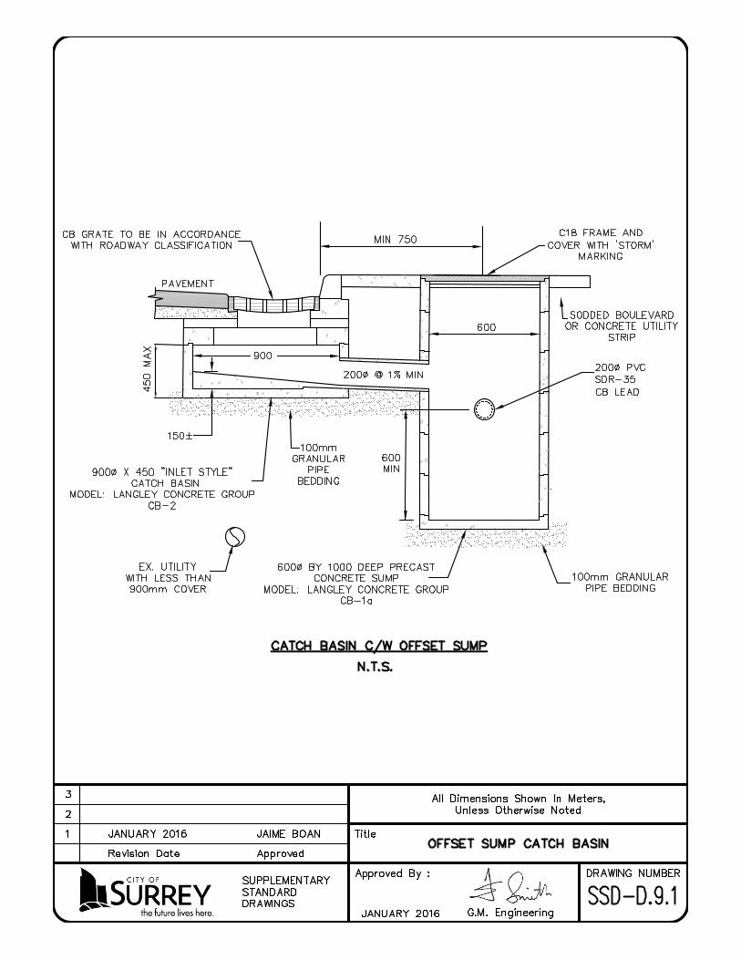


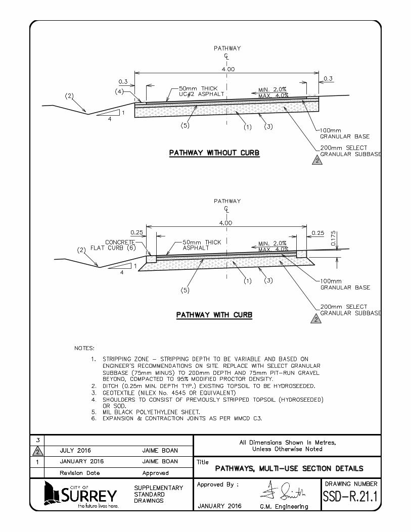


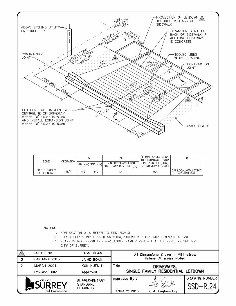
θ
θ

θ
θ


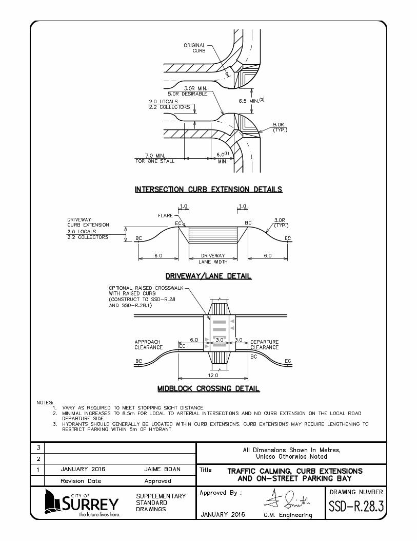


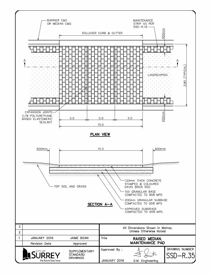

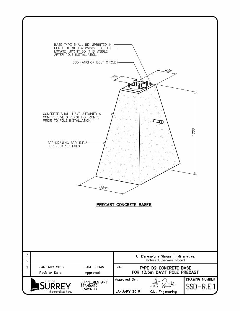


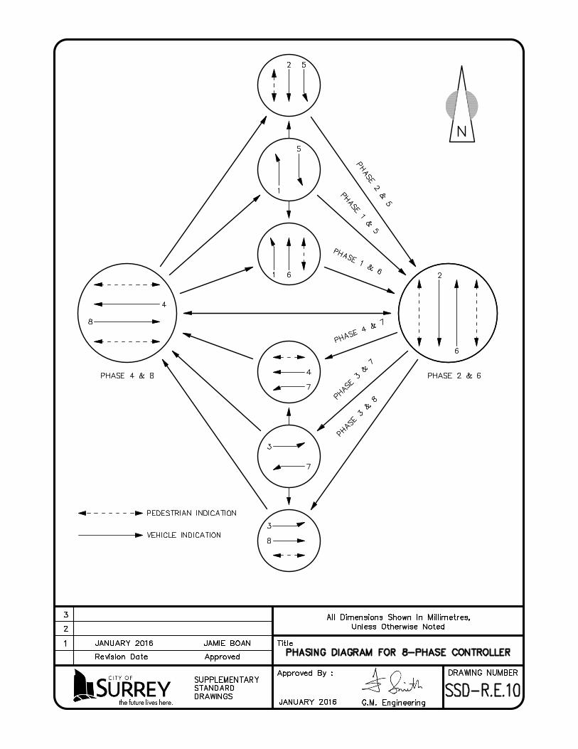


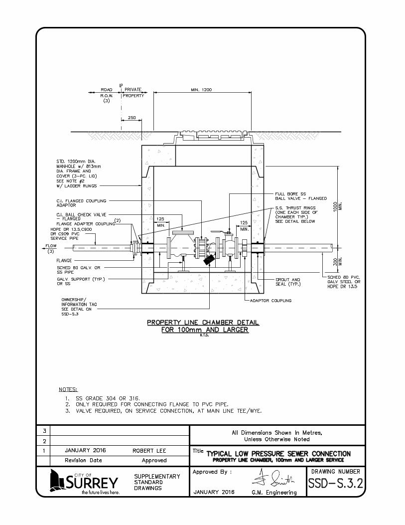


·
·