![2010_BA 9269[1]_Reading 1](https://static.fdocuments.net/doc/165x107/577d367f1a28ab3a6b9340e9/2010ba-92691reading-1.jpg)
Supplemental Information for Current Amendment USA/9269/B ...
13
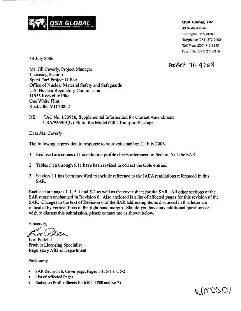
M1 QSA GLOBALf± QSA Global, Inc. 40 North Avenue Burlington, MA 01803 Telephone: (781) 272-2001 Toll Free: (800) 815-1383 Facsimile: (781) 273-2216 14 July 2006 Ms. Jill Caverly, Project Manager Licensing Section Spent Fuel Project Office Office of Nuclear Material Safety and Safeguards U.S. Nuclear Regulatory Commission 11555 Rockville Pike One White Flint Rockville, MD 20852 RE: TAC No. L23950, Supplemental Information for Current Amendment USA/9269/B(U)-96 for the Model 650L Transport Package Dear Ms. Caverly: The following is provided in response to your voicemail on 11 July 2006. 1. Enclosed are copies of the radiation profile sheets referenced in Section 5 of the SAR. 2. Tables 5.1 a through 5.1 c have been revised to correct the table entries. 3. Section 1.1 has been modified to include reference to the IAEA regulations referenced in this SAR. Enclosed are pages 1-1, 5-1 and 5-2 as well as the cover sheet for the SAR. All other sections of the SAR remain unchanged in Revision 6. Also enclosed is a list of affected pages for this revision of the SAR. Changes to the text of Revision 6 of the SAR addressing items discussed in this letter are indicated by vertical lines in the right hand margin. Should you have any additional questions or wish to discuss this submission, please contact me as shown below. Sincerely, dý;_ 62/11eAý Lori Podolak Product Licensing Specialist Regulatory Affairs Department Enclosures: " SAR Revision 6, Cover page, Pages 1-1, 5-1 and 5-2 " List of Affected Pages " Radiation Profile Sheets for 650L TP80 and Se-75 01
Transcript of Supplemental Information for Current Amendment USA/9269/B ...
M1QSA GLOBALf± QSA Global, Inc.
40 North Avenue
Burlington, MA 01803
Telephone: (781) 272-2001
Toll Free: (800) 815-1383
Facsimile: (781) 273-2216
14 July 2006
Ms. Jill Caverly, Project Manager
Licensing SectionSpent Fuel Project OfficeOffice of Nuclear Material Safety and SafeguardsU.S. Nuclear Regulatory Commission11555 Rockville PikeOne White FlintRockville, MD 20852
RE: TAC No. L23950, Supplemental Information for Current AmendmentUSA/9269/B(U)-96 for the Model 650L Transport Package
Dear Ms. Caverly:
The following is provided in response to your voicemail on 11 July 2006.
1. Enclosed are copies of the radiation profile sheets referenced in Section 5 of the SAR.
2. Tables 5.1 a through 5.1 c have been revised to correct the table entries.
3. Section 1.1 has been modified to include reference to the IAEA regulations referenced in thisSAR.
Enclosed are pages 1-1, 5-1 and 5-2 as well as the cover sheet for the SAR. All other sections of theSAR remain unchanged in Revision 6. Also enclosed is a list of affected pages for this revision of theSAR. Changes to the text of Revision 6 of the SAR addressing items discussed in this letter areindicated by vertical lines in the right hand margin. Should you have any additional questions orwish to discuss this submission, please contact me as shown below.
Sincerely,
dý;_ 62/11eAýLori PodolakProduct Licensing SpecialistRegulatory Affairs Department
Enclosures:
" SAR Revision 6, Cover page, Pages 1-1, 5-1 and 5-2" List of Affected Pages" Radiation Profile Sheets for 650L TP80 and Se-75
01
Safety Analysis Report for the Model 650L Transport Package
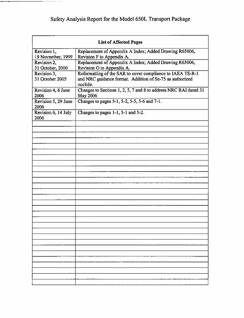
List of Affected Pages
Revision 1, Replacement of Appendix A Index; Added Drawing R65006,19 November, 1999 Revision F to Appendix A.Revision 2, Replacement of Appendix A Index; Added Drawing R65006,31 October, 2000 Revision G to Appendix A.Revision 3, Reformatting of the SAR to cover compliance to IAEA TS-R-131 October 2005 and NRC guidance format. Addition of Se-75 as authorized
nuclide.Revision 4, 6 June Changes to Sections 1, 2, 5, 7 and 8 to address NRC RAI dated 312006 May 2006Revision 5, 29 June Changes to pages 5-1, 5-2, 5-5, 5-6 and 7-1.2006Revision 6, 14 July Changes to pages 1-1, 5-1 and 5-2.2006
+
1*
+
+
+
+
+
+
Safety Analysis Report
QSA Global Inc.
Model 650LType B(U) - 96
Transport Package
14 July 2006
Revision 6
Safety Analysis Report for the Model 650L Transport Package
QSA Global Inc. 14 July 2006 - Revision 6Burlington, Massachusetts Page 1-1
Section 1 - GENERAL INFORMATION
1.1 Introduction
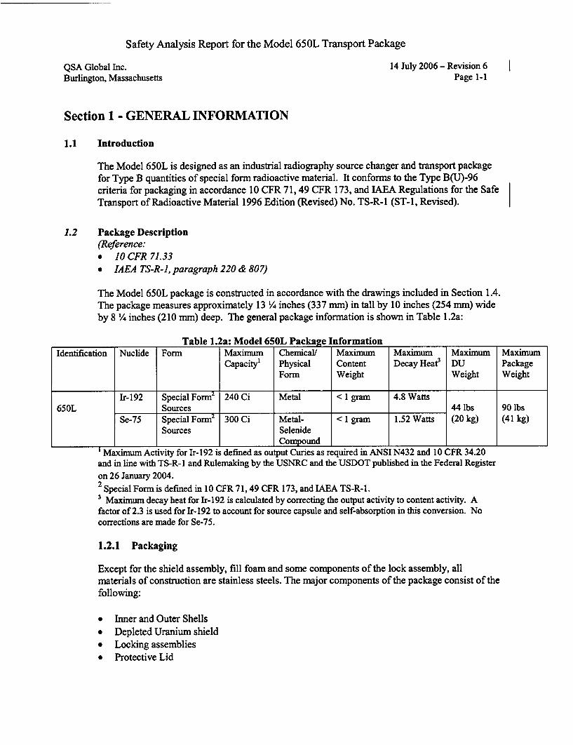
The Model 650L is designed as an industrial radiography source changer and transport package
for Type B quantities of special form radioactive material. It conforms to the Type B(U)-96
criteria for packaging in accordance 10 CFR 71, 49 CFR 173, and IAEA Regulations for the Safe
Transport of Radioactive Material 1996 Edition (Revised) No. TS-R-1 (ST-i, Revised).
1.2 Package Description(Reference:* 10 CFR 71.33
* IAEA TS-R-1, paragraph 220 & 807)
The Model 650L package is constructed in accordance with the drawings included in Section 1.4.The package measures approximately 13 ¼ inches (337 mm) in tall by 10 inches (254 mm) wideby 8 ¼ inches (210 umm) deep. The general package information is shown in Table 1.2a:
Table 1.2a: Model 650L Package InformationIdentification Nuclide Form Maximum Chemical! Maximum Maximum Maximum Maximum
Capacity' Physical Content Decay Heat3 DU PackageForm Weight Weight Weight
Ir-192 Special Form2 240 Ci Metal < 1 gram 4.8 Watts650L Sources 44 lbs 90 lbs
Se-75 Special Form2 300 Ci Metal- < 1 gram 1.52 Watts (20 kg) (41 kg)Sources Selenide
Compound'Maximum Activity for Ir-192 is defined as output Curies as required in ANSI N432 and 10 CFR 34.20and in line with TS-R-1 and Rulemaking by the USNRC and the USDOT published in the Federal Register
on 26 January 2004.2 Special Form is defined in 10 CFR 71, 49 CFR 173, and IAEA TS-R-1.3 Maximum decay heat for Ir-192 is calculated by correcting the output activity to content activity. Afactor of 2.3 is used for Ir-192 to account for source capsule and self-absorption in this conversion. Nocorrections are made for Se-75.
1.2.1 Packaging
Except for the shield assembly, fill foam and some components of the lock assembly, allmaterials of construction are stainless steels. The major components of the package consist of the
following:
* Inner and Outer Shells
* Depleted Uranium shield* Locking assemblies* Protective Lid
Safety Analysis Report for the Model 650L Transport Package
QSA Global Inc. 14 July 2006 - Revision 6Burlington, Massachusetts Page 5-1
Section 5 - SHIELDING EVALUATION
5.1 Description of Shielding Design(Reference:* USNRC, 10 CFR 71.31• IAEA TS-R-1, paragraph 701 and 702)
5.1.1 Design Features
The principal shielding in the Model 650L transport package is the depleted uranium shieldassembly. In some cases additional supplemental lead shielding is added to the shield assemblyas described in the drawings included in Section 1.4.
5.1.2 Summary Table of Maximum Radiation Levels
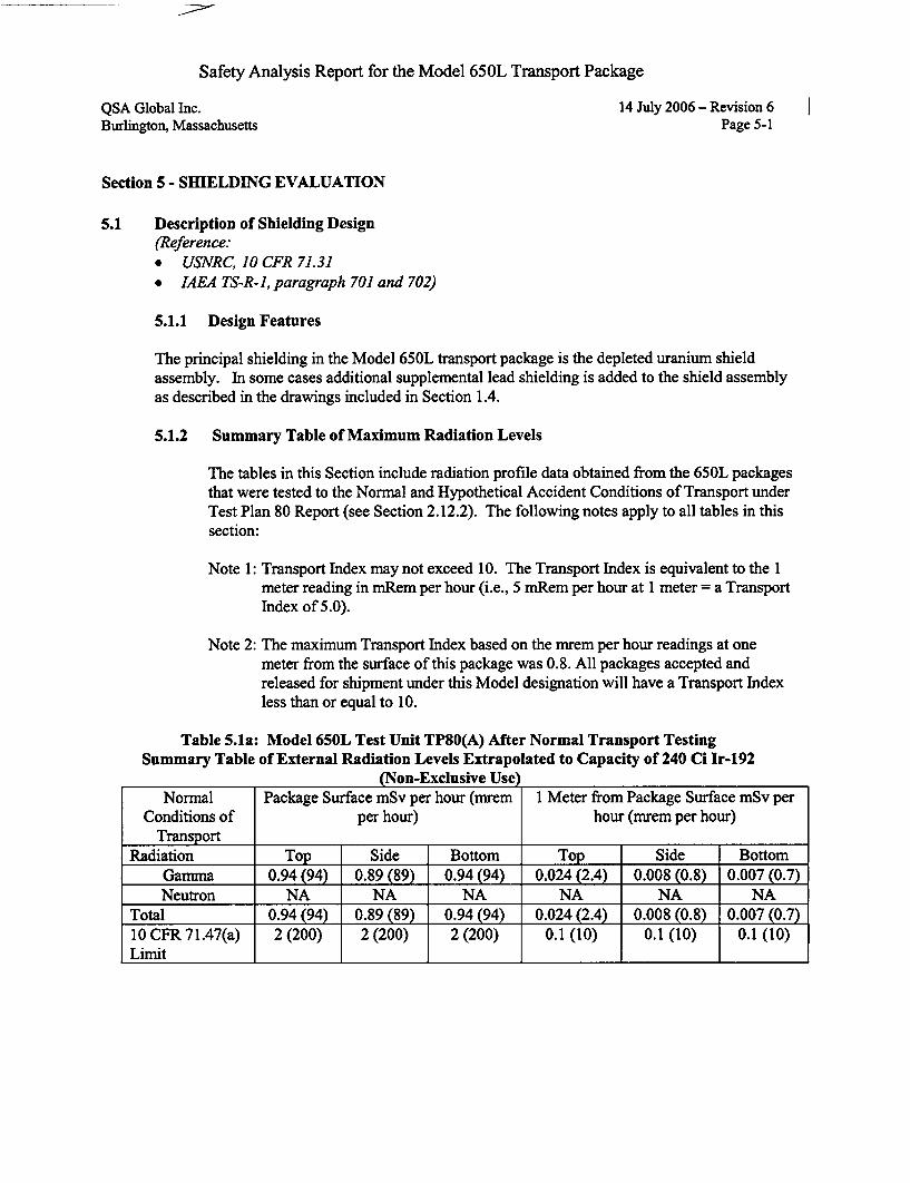
The tables in this Section include radiation profile data obtained from the 650L packagesthat were tested to the Normal and Hypothetical Accident Conditions of Transport underTest Plan 80 Report (see Section 2.12.2). The following notes apply to all tables in thissection:
Note 1: Transport Index may not exceed 10. The Transport Index is equivalent to the 1meter reading in mRem per hour (i.e., 5 mRem per hour at 1 meter = a TransportIndex of 5.0).
Note 2: The maximum Transport Index based on the mrem per hour readings at onemeter from the surface of this package was 0.8. All packages accepted andreleased for shipment under this Model designation will have a Transport Indexless than or equal to 10.
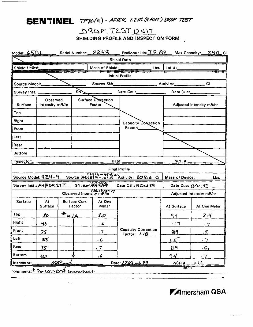
Table 5.1a: Model 650L Test Unit TP80(A) After Normal Transport TestingSummary Table of External Radiation Levels Extrapolated to Capacity of 240 Ci Ir-192
(Non-Exclusive Use)Normal Package Surface mSv per hour (mrem 1 Meter from Package Surface mSv per
Conditions of per hour) hour (mrem per hour)Transport
Radiation Top Side Bottom Top Side BottomGamma 0.94 (94) 0.89 (89) 0.94 (94) 0.024(2.4) 0.008 (0.8) 0.007 (0.7)Neutron NA NA NA NA NA NA
Total 0.94 (94) 0.89 (89) 0.94 (94) 0.024(2.4) 0.008 (0.8) 0.007 (0.7)10 CFR 71.47(a) 2(200) 2(200) 2(200) 0.1(10) 0.1(10) 0.1(10)Limit I I
Safety Analysis Report for the Model 650L Transport Package
QSA Global Inc.Burlington, Massachusetts
14 July 2006 - Revision 6Page 5-2
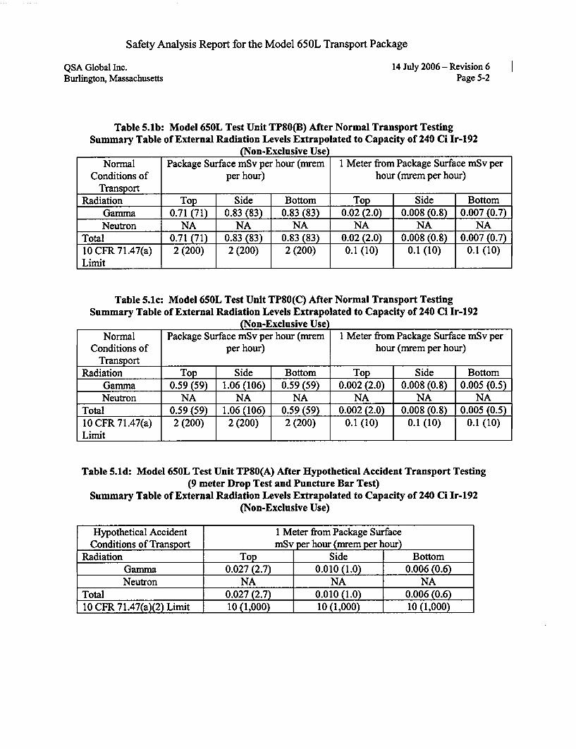
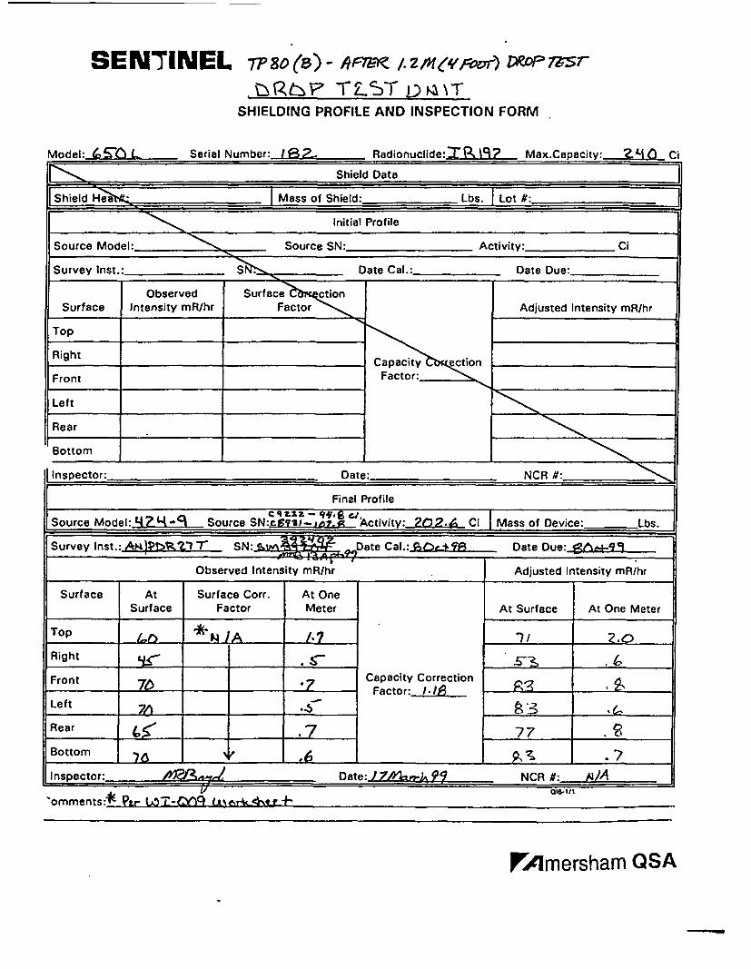
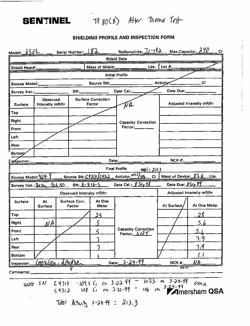
Table 5.1b: Model 650L Test Unit TP80(B) After Normal Transport TestingSummary Table of External Radiation Levels Extrapolated to Capacity of 240 Ci Ir-192
(Non-Exclusive Use)Normal Package Surface mSv per hour (mrem 1 Meter from Package Surface mSv per
Conditions of per hour) hour (mrem per hour)Transport
Radiation Top Side Bottom Top Side BottomGamma 0.71 (71) 0.83 (83) 0.83 (83) 0.02 (2.0) 0.008 (0.8) 0.007 (0.7)Neutron NA NA NA NA NA NA
Total 0.71 (71) 0.83 (83) 0.83 (83) 0.02 (2.0) 0.008 (0.8) 0.007 (0.7)10 CFR 71.47(a) 2(200) 2(200) 2(200) 0.1(10) 0.1(10) 0.1(10)Limit I
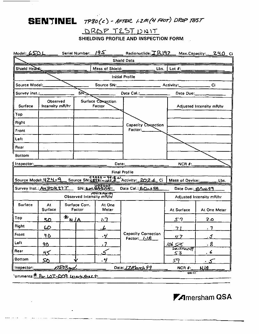
Table 5.1c: Model 650L Test Unit TP80(C) After Normal Transport TestingSummary Table of External Radiation Levels Extrapolated to Capacity of 240 Ci Ir-192
(Non-Exclusive Use)Normal Package Surface mSv per hour (mrem 1 Meter from Package Surface mSv per
Conditions of per hour) hour (mrem per hour)Transport
Radiation Top Side Bottom Top Side BottomGamma 0.59 (59) 1.06 (106) 0.59 (59) 0.002 (2.0) 0.008 (0.8) 0.005 (0.5)Neutron NA NA NA NA NA NA
Total 0.59 (59) 1.06 (106) 0.59 (59) 0.002 (2.0) 0.008 (0.8) 0.005 (0.5)10 CFR 71.47(a) 2 (200) 2 (200) 2 (200) 0.1 (10) 0.1 (10) 0.1 (10)Limit
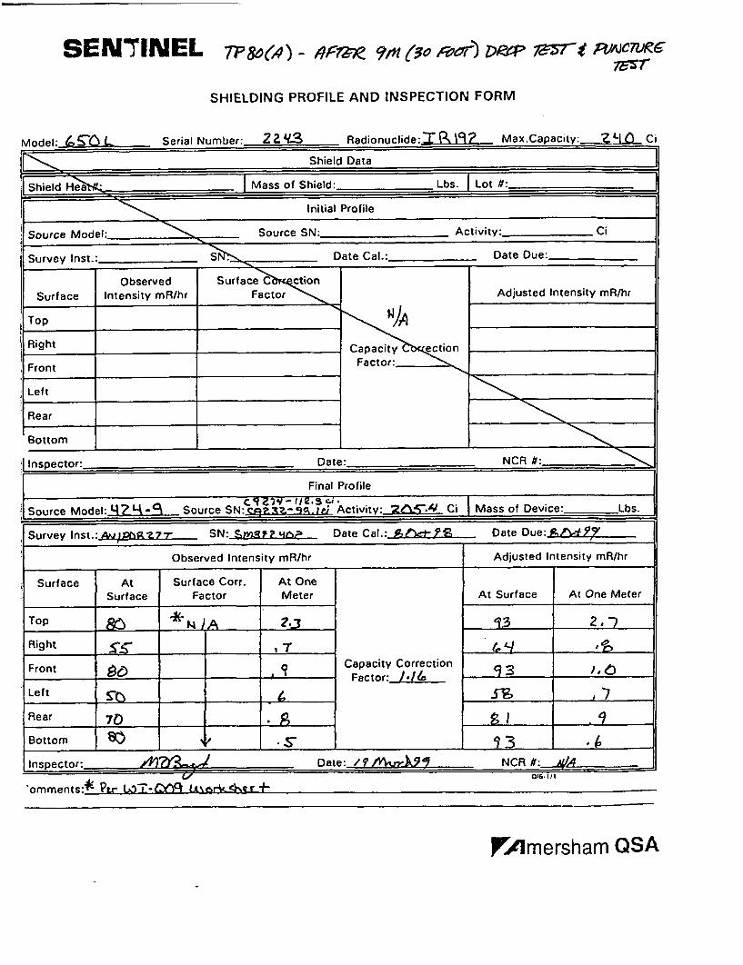
Table 5.1d: Model 650L Test Unit TP80(A) After Hypothetical Accident Transport Testing(9 meter Drop Test and Puncture Bar Test)
Summary Table of External Radiation Levels Extrapolated to Capacity of 240 Ci Ir-192(Non-Exclusive Use)
Hypothetical Accident 1 Meter from Package SurfaceConditions of Transport mSv per hour (mrem per hour)
Radiation Top Side BottomGamma 0.027 (2.7) 0.010 (1.0) 0.006 (0.6)Neutron NA NA NA
Total 0.027 (2.7) 0.010 (1.0) 0.006 (0.6)10 CFR 71.47(a)(2) Limit 10 (1,000) 10 (1,000) 10 (1,000)
SENTINEL Tp7'?go()- AF&-C/.z)C /% Z6 r) MP 7Z-Z-
,tý "-L,'F TLST QD NTSHIELDING PROFILE AND INSPECTION FORM
Model:. LSerial Number: 22. LV ..S Radionuclide:.=I,_ 2.._. Max.Capacity: '.ZHD Ci
Shield Data
Shield H-a Mass of Shield: Lbs. I Lot #:
Initial Profile
Source Model: Source SN: Activity: Ci
Survey Inst.:__ Date Cal.: Date Due:
SObservedIntensity mR/hr
!
Surface CtionFactorSurface
Top
Right
Front
Left
Rear
Adjusted Intensity mR/hr
Capacity ctionFactor:
Bottom
Insoector: Date: NCR N:
Final Profile
Cqourc -- dt:t,_ C, tSource Model:~ .._•-•: Source SN: tivi.v.ct2±Ey: 6 Ci I Mass of Device: Lbs.
Survey Inst.: Ai4,3Pt2P,?." -r SN: su Z; Date Cal.: h V•,.-i• Date Due:._6&03
Observed Intensity mR/nr Adjusted Intensity mR/hr
Surface At Surface Corr. At One
Surface Factor Meter At Surface At One Meter
Top 86 * N2AZ0 LI 2,1/
Right .6 j Ll "7 -
Front 7S-__ "7 Capacity CorrectionFactor: I./-i
Left t'_ _ ,
Rear , 7 ____.__.
Bottom C> 14 7
Inspector: "lag• Date: 7,10u-l 92 NCR #:, ?tiA
omments:*-hr w,-OT-wcfY rk-,cAtr016-1/1
FAmersham QSA
SENTINEL
SHIELDING PROFILE AND INSPECTION FORM
Model:. ! .•as() Serial Number:.2, 13 - Radionuclide:.,L..RJ91.Q Z.. Max.Capacity:_..L Ci
Shield Data
Shield Heaen . Mass of Shield: Lbs. I Lot #:
Initial Profile
Source Model:- Source SN: Activity: Ci
Survey Inst.: Date Cal.: Date Due:
Observed Surface ctionSurface Intensity mR/hr Factor Adjusted Intensity mR/hr
Top
Right _____________________Capacity ection
Front Factor:
Left
Rear
Bottom
Inspector: Date:_ NCR #:
Final Profile
Source Model:2 Z_1O•-3. Source SN:eggSU-. 1 I.'t Activity:._.ý,- Ci Mass of Device: - Lbs.
Survey Inst.: .m)!Pt>,k?_l -r SN 4-v^ Date Cal.:. ? Date Due:
Observed Intensity mR/hr Adjusted Intensity mR/hr
Surface At Surface Corr. At One
Surface Factor Meter At Surface At One Meter
Top L,• 'k ,, ' • ,
Right .- '
Front Capacity Correctiont76 7 Factor: -1,1
Left 7*, J___"- __
Rear C", 7 77 .
Bottom 76 -? 6 S -7
Inspector:_ Date: I /4-,-zzo 9? NCR #: R -/A
omments:* Plr LZOT-=9 c LI%6r1A-%tr-_+-
rAmersham QSA
SENTINEL 77pon (e ) - 4Fm /. z~n &i r-oor) Daop Tms
i~ tl,~'F LST L)D TSHIELDING PROFILE AND INSPECTION FORM
Model: ~ L Serial Number: Radionuclide:TR 19? Mac.Caoacitv: 2L4f~ (1
Shield Data
[Shield Hea Mass of Shield: Lbs. I Lot #:_ _ _
I Initial Profile
Source Model: Source SN: Activity: Ci
Survey Inst.: S Date Cal.: Date Due:
Observed Surface C ction
Surface Intensity mR/hr Factor Adjusted Intensity mR/hr
Top
Right Capacity ection
Front Factor"
Left
Rear
Bottom
Inspector: Date: NCR #:_ _ _ _
Final Profile ]Source Model:_ .- . Source SNcv-- ,.2tvA: Ci Mass of Device: Lbs.
Survey Inst.: A•• %7'b.T" SN: % 4A Date Cal.: V,. ÷+f _ Date Due: .•,4q=91
Observed Intensity mR/hr Adjusted Intensity mR/hr
Surface At Surface Corr. At OneSurface Factor Meter At Surface At One Meter
Top S% N JA .--?
Right .0, " 7Ronht (Capacity Correction
Front 4 ("Factor: I,/J AlZ7 .4,
Left-/ a
Rear low,
Bottom •• • c -
Inspector: i•_ v•/i Date: I 7/A4Jz= 92 NCR #:. W
omments:* P't- L4T-)9 LPtrgif_, 1./
rAmersham QSA
SENTINEL 7rg6C1)- va~e zr ()o xivar) ze ro-7r rAC7U
SHIELDING PROFILE AND INSPECTION FORM
.. I,. 4 C"\ I crI-l Nuimhpbr- 2 2'LS Radionuclide: TR•?9 Max.Capacity: -. Z 1 Ci
Shield Data
Shield Hea Mass of Shield: Lbs. [ Lot #:
Initial Profile
Source Model: Source SN: Activity: Ci
Survey Inst.: S Date Cal.: Date Due:
Observed Surface C ctionSurface Intensity mR/hr Factor Adjusted Intensity mR/hr
Top ')A
Right Capacity ectionFctor:
Front F c.
Left
Rear
Bottom
[Inspector: Date: NCR #:
[ Final Profile
&A ... U7.. -,A LIq..r•> n,,i .- : Ar5jtivitu "•,7;', . Ci I Mass of Device: Lbs.:!
Survey Inst.: Aq bpt.7"r SN: Ai r ..His. Date Cal.: Date Due: &,14,92!
Observed Intensity mR/hr Adjusted Intensity mR/hr
Surface At Surface Corr. At OneSurface Factor Meter At Surface At One Meter
Top -' N)A ?. 21-7
Right ___._ , , is
Front Capacity CorrectionFactor:..L . --- 1" --
Left _____ _ _
Rear 70 •9__ ___,
Bottom 33• _-_ __ __• __
Inspector: J ?".• Date: 1/?& rWJ5 NCR #: ,AV
o m m e n ts :4 6 P uu L % , - t -6 . -
VAmersham QSA
SENTINEL -re o ( 0 A4+ Theid f/eý
SHIELDING PROFILE AND INSPECTION FORM
" A .I t. iL ~orinI Mmtmh~r~ I ~ Rndionu~Iid~ T!i -1 a?~ Max.Caoacitv: dLy0 Ci
Shield Data
Shield Heat#:__ Mass of Shield: Lbs. I Lot #:
Initial Profile
Source Model: Source SN: Activi . Ci
Survey Inst.: SN: Date Cal.: Date Due:
Observed Surface CorrectionSurface Intensity mR/hr Factor Adjusted Intensity mR/hr
Top
Right __Capacity Correction
Front Factor:
Left
Rear
Botto e
0pector: Date: NCR #:
Final Profile "tI• A: o73,3
Source Model:t10L- .. Source SN: C Activity: bo7/jdG Ci Mass of Device: _k. . Lbs.
Survey Inst.: 3V(6• fez. Lk . SN: 9- Date Cal.: f Sep/ fI Date Due: io4E, . ....
Observed Intensity mR/hr Adjusted Intensity mR/hr
Surface At Surface Corr. At OneSurface Factor Meter At Surface At One Meter
Top
Right
Front Capacity CorrectionFactor: JIt 0 "
Left
Rear
Bottom /_ _ _ _ (.i
, Inspector: • 'k•(Af7d' T Date: ..-L;_q- NCR #:on -o 016-1es
Comments:
C q31 ;-(CC.,l
c,, 3-•:--qAl- Io7?,b f 3.•-,?V-f 6,M,C 3- 2. q- 'Tq
- -• 3 rAmersham QSA
TAI bvtA -- 213,3
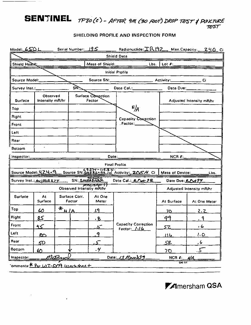
SENI7NEL 7P YO (e- AF7W '?M9 6(30 ,O r) DROP 73ý-r- e PLAC 7M6.7Vý7-
SHIELDING PROFILE AND INSPECTION FORM
Model: 5'0 L Serial Number: 19.5 Radionuclide:%Ra.. Max.Capacity, .M'f Ci
Shield Data
Shield H _ i Mass of Shield: Lbs. I Lot W:
Initial Profile
Source Model: Source SN: _ Activity: Ci
Survey Inst.: S Date Cal.: Date Due:
ObservedIntensity mR/hr
Surface •C ctionFactorSurface Adjusted Intensity mR/hr
Top
Right
Front
Left
Rear
Capacity ectionFactor:
E~EIII~Bottom
Inspector: Date: NCR N:
Final Profile
..--.. Source Mode Z- Source SN: 1 Activity:- 2A. Ci Mass of Device: Lbs.
Survey Inst.: AwA Z-r SN:_. Date Cal.:- _?e_,_P Date Due: .&.•^492/7IV46 WVS~ 1 2
Observed Intensity mR/hr Adjusted Intensity mR/hr
Surface At Surface Corr. At OneSurface Factor Meter At Surface At One Meter
Top N /A 320
Right _"-q '
Front ..• Capacity Correction
Left ___,
Rear , .s-•' ,
Bottom ,D, NCR #: _ ___
Inspector:_ JJ.~I Date: /ff~4~NCR f:..$4...
"omments:*E Pi- WT-0y L& % tgr -0's.','
!'Amersham QSA
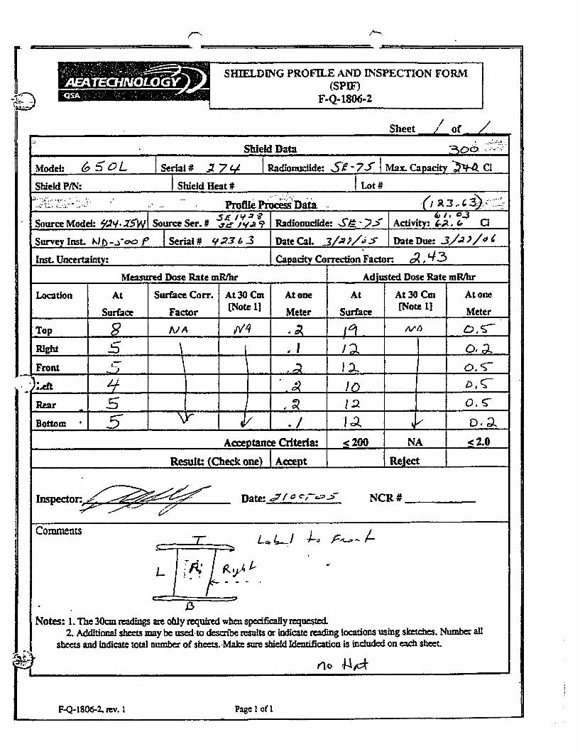
YV#SHIELDING PROFULE AND 04SPECTION FORMýýPr ,(spIF)M F.Q-1806-2
Sheet // of /
Shield Data
Model: 6 " Serial # - 7 / Radionuclide: S;F 7_ " Max. Capacity Z CI
Shield P/N: Shield Heat # Lot #
" Profile Pr sData -i. . --).
Source Model: W'Y/.Z5W Source Ser. # r-- ya 9 Radionuclide: S•- -25 I Activity: tA, 0 i
Survey Inst. Nb-.oe. Serial# '1.•36-3 DateCal. 3 1.,JP . S DatefDue: _3,.-?,ýl "
Inst. Uncertainty: Capayorrection Factor. '• R,43Measured Dose Rate mR/hr Adjusted Dose Rate mR/hr
Location At Surface Corr. At 30 Cm Atone At At 30 Cm Atone
Surface Factor (Note 11 Meter Surface [Note 1] Meter
Top 2 A/A bvq "i . /V 6'_
Front . -
LeAft A _
Rea 5 -_ _, j.2 0_/
Bottom •a_ . /__ _ D,_ a
Acceptance Criteria: < 200 NA < 2.0
Result: (Check one) Accept Reject _ _
Inspectr. 4•II Date: ,71f c~-;---:; NCR #______
Comnments L... - ,---
Notes: I. The 30cm readings are ohly required when specifically requested.2. Additional shees may be used to descnbe results or indicate reading locations using sixthe. Number all
sheets and indicate total number of sheet..-Maim sure shield Identification is included on each sheet.
n~o .t•,=o
F-Q- 1806-2. rev. I Page I of IF-Q- 1806-2, rev. I Page 1 oft