Supplement to the WSAA Sewerage Code of Australia - Barwon Water to the... · Introduction . Barwon...
22
Supplementary information to the WSAA Sewerage Code of Australia Melbourne retail water agencies edition Version 1.0 WSA 02-2002-2.3 For land development
Transcript of Supplement to the WSAA Sewerage Code of Australia - Barwon Water to the... · Introduction . Barwon...
Supplementary information to the WSAA Sewerage Code of Australia Melbourne retail water agencies edition Version 1.0 WSA 02-2002-2.3 For land development
Table of contents Part 1: Planning and design .............................................................................................................................. 5
2. System planning .......................................................................................................................................... 5
2.1 Sewerage system philosophy and definition ......................................................................................... 5
3. Flow estimation ............................................................................................................................................ 5
3.2. Design flow estimation method ........................................................................................................... 5
4. Detail design ............................................................................................................................................... 5
5. Property connection ................................................................................................................................... 7
5.2. Limitations of connections to sewers ................................................................................................... 7
5.4 Maximum depth of property connections ............................................................................................ 7
5.7. Y- Property connections ...................................................................................................................... 7
5.8. Length of property connection sewers ................................................................................................ 8
5.10. Retaining walls .................................................................................................................................... 8
6. Maintenance structures .............................................................................................................................. 8
6.1 Types of maintenance structures .......................................................................................................... 8
6.3 Spacing of maintenance structures ....................................................................................................... 8
6.4 Special consideration for location of maintenance structures ............................................................. 8
6.7 Maintenance Shafts (MS) ...................................................................................................................... 9
7. Ancillary structures ...................................................................................................................................... 9
7.3. Water seals and gas check maintenance holes (MH) ........................................................................... 9
7.6. Near horizontal boreholes ................................................................................................................... 9
8. Structural design ........................................................................................................................................ 10
8.8. PIpe cover .......................................................................................................................................... 10
8.10. Bulkheads and trenchstops .............................................................................................................. 10
9. Design review and drawings ...................................................................................................................... 10
9.2 Design drawings ................................................................................................................................ 10
9.3 Drafting standards ............................................................................................................................. 10
Part 2: Products and materials ........................................................................................................................ 14
Part 3: Construction ........................................................................................................................................ 15
12 Quality ........................................................................................................................................................ 15
14 Products and materials ............................................................................................................................... 15
18 Maintenance Holes (MH)........................................................................................................................15
22.6 Deflection (ovality) testing of flexible sewers ................................................................................... 16
22.7 CCTV inspection ............................................................................................................................... 16
24 Connection to existing sewers................................................................................................................. 16
26 Work as constructed details .................................................................................................................... 16
Part 4: Standard drawings ............................................................................................................................... 17
NOTE: THE CLAUSE AND SECTION NUMBERS MATCH THOSE THAT ARE USED IN THE MELBOURNE RETAIL WATER AGENCIES VERSION OF THE WSAA SEWER RETICULATION CODE (WSA 02-2002-2.3)
Supporting documentation – Sewerage Code Introduction Barwon Water’s design and constructions requirements for sewer mains required for the provision of services to subdivisions and other land development works is the Water Services Association of Australia Sewerage Code of Australia WSA 02-2002-2.3 Retail Water Agencies Edition Version 1 with the exceptions listed in this supplement. General This supplementary documentation describes Barwon Water’s specific requirements for sewerage works additional to those detailed in the WSAA Sewerage Code of Australia WSA-02-2002-2.3 - Melbourne Retail Water Agencies Edition - Version 1. The Supplementary section of the Water Reticulation Code contains:
• Table of contents to the supplementary Documentation • Description of Barwon Water requirements where required or different to the WSAA Code
Operation The clause numbering of this supplementary document matches the WSAA Code. Innovative solutions WSAA Sewerage Code of Australia and this supporting documentation provide ‘deemed-to-comply’ solutions for the creation of all water agency sewerage assets. Alternative solutions, practices, equipment and methodologies will continue to evolve and offer opportunities to improve the creation of these assets. Barwon Water encourages use of any innovation that offers enhanced productivity and serviceability, but Barwon Water input should be sought before any new system is designed. Responsibilities Designers and constructors are responsible for their respective aspects of the design and construction process. It is the designer/constructor’s responsibility to justify any variation from the requirements set out in the Sewerage Code of Australia (including the attached Barwon Water conditions) and/or the Barwon Water Construction Drawings - plus any specific directions given by Barwon Water for a particular project. The designer/constructor is to obtain Barwon Water endorsement for any variation.
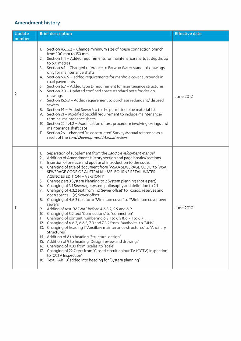
Amendment history Update number
Brief description Effective date
2
1. Section 4.6.5.2 – Change minimum size of house connection branch
from 100 mm to 150 mm 2. Section 5.4 – Added requirements for maintenance shafts at depths up
to 6.0 metres 3. Section 6.1 – Changed reference to Barwon Water standard drawings
only for maintenance shafts 4. Section 6.6.9 – added requirements for manhole cover surrounds in
road pavements 5. Section 6.7 – Added type D requirement for maintenance structures 6. Section 9.3 – Updated confined space standard note for design
drawings 7. Section 15.5.3 – Added requirement to purchase redundant/ disused
sewers 8. Section 14 – Added SewerPro to the permitted pipe material list 9. Section 21 – Modified backfill requirement to include maintenance/
terminal maintenance shafts 10. Section 22.4.4.2 – Modification of test procedure involving o-rings and
maintenance shaft caps 11. Section 26 – changed ‘as constructed’ Survey Manual reference as a
result of the Land Development Manual review
June 2012
1
1. Separation of supplement from the Land Development Manual 2. Addition of Amendment History section and page breaks/sections 3. Insertion of preface and update of introduction to the code. 4. Changing of title of document from ‘WSAA SEWERAGE CODE’ to ‘WSA
SEWERAGE CODE OF AUSTRALIA - MELBOURNE RETAIL WATER AGENCIES EDITION – VERSION 1’
5. Change part 3 System Planning to 2 System planning (not a part) 6. Changing of 3.1 Sewerage system philosophy and definition to 2.1 7. Changing of 4.3.2 text from ’(c) Sewer offset’ to ’Roads, reserves and
open spaces – (c) Sewer offset’ 8. Changing of 4.6.3 text form ’Minimum cover’ to “Minimum cover over
sewers’ 9. Adding of text “MRWA” before 4.6.5.2, 5.9 and 6.9 10. Changing of 5.2 text ’Connections’ to ’connection’ 11. Changing of content numbering 6.3.1 to 6.3 & 6.7.1 to 6.7 12. Changing of 6.6.2, 6.6.5, 7.3 and 7.3.2 from ’Manholes’ to ’MHs’ 13. Changing of heading 7 ’Ancillary maintenance structures’ to ’Ancillary
Structures’ 14. Addition of 8 to heading ’Structural design’ 15. Addition of 9 to heading ’Design review and drawings’ 16. Changing of 9.3.1 from ’scales’ to ’scale’ 17. Changing of 22.7 text from ‘Closed circuit colour TV (CCTV) Inspection’
to ’CCTV Inspection’ 18. Text ’PART 3’ added into heading for ‘System planning’
June 2010
5
Part 1: Planning and design
2. System planning
2.1 Sewerage system philosophy and definition
2.1.4.2 Sewage pumping stations (SPS’s)
Barwon Water does not support the ’other options…. e.g. vacuum sewerage and pressure sewerage systems’., Therefore, these types of systems may not be approved except in exceptional circumstances.
3. Flow estimation
3.2. Design flow estimation method
3.2.2 Traditional design flow estimation method
Sewer is designed for peak wet weather flows at two thirds full capacity.
Average dry weather flow 200 l/h/d Average peak wet weather flow 800 l/h/d Number of persons per tenement 3.5 Multi-tenement development (residential) 1 unit = 0.65 House Maximum flow 150mm 2/3 cap. at P.W.W.F.
225mm " 300mm " Calculations based on Kutter's formula, n = 0.013. (Equivalent to Mannings formula with ‘n’ = 0.014)
4. Detail design
4.2.5 Easements
Easements are to be in accordance with the Land Tenure Guidelines set out in section 3.2.3 (policy section) of Barwon Water’s Land Development Manual.
4.3.2 Roads, reserves and Open Space - c) Sewer offset
Minimum offset of a sewer main within the front boundary of any lot to be 2.0 metres.
4.3.6. Dead ends
Addition to clause. All sewer stubs for future connections shall be designed at the correct grade for future sewers.
4.3.7 Horizontal curves in sewer.
Pipe curvature may only be achieved by cumulative deflection at pipe joints. Design shall specify pipe proposed to be used. Manufacturer’s recommended maximum joint deflection for those pipes shall be provided with the design.
4.5.4. Minimum pipe size for maintenance purposes.
Table 4.3 in code not to be used. Refer to table shown in 4.5.5 below.
6
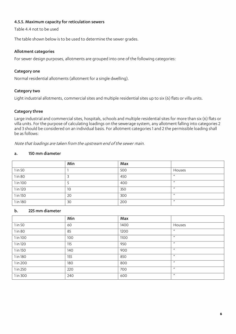
4.5.5. Maximum capacity for reticulation sewers
Table 4.4 not to be used The table shown below is to be used to determine the sewer grades.
Allotment categories
For sewer design purposes, allotments are grouped into one of the following categories:
Category one
Normal residential allotments (allotment for a single dwelling).
Category two
Light industrial allotments, commercial sites and multiple residential sites up to six (6) flats or villa units.
Category three
Large industrial and commercial sites, hospitals, schools and multiple residential sites for more than six (6) flats or villa units. For the purpose of calculating loadings on the sewerage system, any allotment falling into categories 2 and 3 should be considered on an individual basis. For allotment categories 1 and 2 the permissible loading shall be as follows: Note that loadings are taken from the upstream end of the sewer main. a. 150 mm diameter
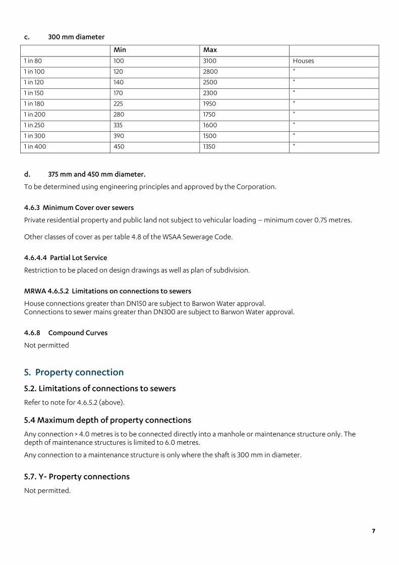
b. 225 mm diameter
Min Max
1 in 50 60 1400 Houses
1 in 80 85 1200 “
1 in 100 100 1100 “
1 in 120 115 950 “
1 in 150 140 900 “
1 in 180 155 850 “
1 in 200 180 800 “
1 in 250 220 700 “
1 in 300 240 600 “
Min Max
1 in 50 1 500 Houses
1 in 80 3 450 “
1 in 100 5 400 “
1 in 120 10 350 “
1 in 150 20 300 “
1 in 180 30 200 “
7
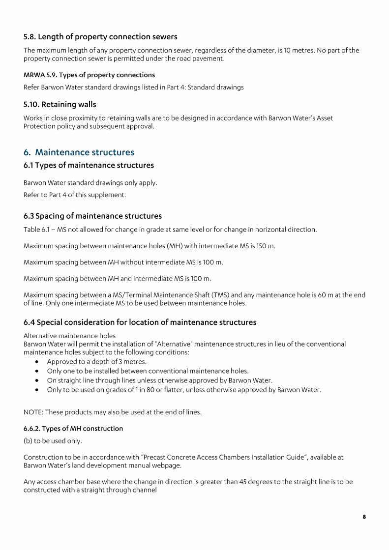
c. 300 mm diameter
Min Max
1 in 80 100 3100 Houses
1 in 100 120 2800 "
1 in 120 140 2500 "
1 in 150 170 2300 "
1 in 180 225 1950 "
1 in 200 280 1750 "
1 in 250 335 1600 "
1 in 300 390 1500 "
1 in 400 450 1350 "
d. 375 mm and 450 mm diameter.
To be determined using engineering principles and approved by the Corporation.
4.6.3 Minimum Cover over sewers
Private residential property and public land not subject to vehicular loading – minimum cover 0.75 metres. Other classes of cover as per table 4.8 of the WSAA Sewerage Code.
4.6.4.4 Partial Lot Service
Restriction to be placed on design drawings as well as plan of subdivision.
MRWA 4.6.5.2 Limitations on connections to sewers
House connections greater than DN150 are subject to Barwon Water approval. Connections to sewer mains greater than DN300 are subject to Barwon Water approval.
4.6.8 Compound Curves
Not permitted
5. Property connection
5.2. Limitations of connections to sewers
Refer to note for 4.6.5.2 (above). 5.4 Maximum depth of property connections
Any connection > 4.0 metres is to be connected directly into a manhole or maintenance structure only. The depth of maintenance structures is limited to 6.0 metres.
Any connection to a maintenance structure is only where the shaft is 300 mm in diameter.
5.7. Y- Property connections
Not permitted.
8
5.8. Length of property connection sewers
The maximum length of any property connection sewer, regardless of the diameter, is 10 metres. No part of the property connection sewer is permitted under the road pavement. MRWA 5.9. Types of property connections
Refer Barwon Water standard drawings listed in Part 4: Standard drawings 5.10. Retaining walls
Works in close proximity to retaining walls are to be designed in accordance with Barwon Water’s Asset Protection policy and subsequent approval.
6. Maintenance structures 6.1 Types of maintenance structures
Barwon Water standard drawings only apply.
Refer to Part 4 of this supplement.
6.3 Spacing of maintenance structures
Table 6.1 – MS not allowed for change in grade at same level or for change in horizontal direction. Maximum spacing between maintenance holes (MH) with intermediate MS is 150 m. Maximum spacing between MH without intermediate MS is 100 m. Maximum spacing between MH and intermediate MS is 100 m. Maximum spacing between a MS/Terminal Maintenance Shaft (TMS) and any maintenance hole is 60 m at the end of line. Only one intermediate MS to be used between maintenance holes.
6.4 Special consideration for location of maintenance structures
Alternative maintenance holes Barwon Water will permit the installation of "Alternative" maintenance structures in lieu of the conventional maintenance holes subject to the following conditions:
• Approved to a depth of 3 metres. • Only one to be installed between conventional maintenance holes. • On straight line through lines unless otherwise approved by Barwon Water. • Only to be used on grades of 1 in 80 or flatter, unless otherwise approved by Barwon Water.
NOTE: These products may also be used at the end of lines. 6.6.2. Types of MH construction
(b) to be used only. Construction to be in accordance with “Precast Concrete Access Chambers Installation Guide”, available at Barwon Water’s land development manual webpage. Any access chamber base where the change in direction is greater than 45 degrees to the straight line is to be constructed with a straight through channel
9
6.6.5. Diameters of MH
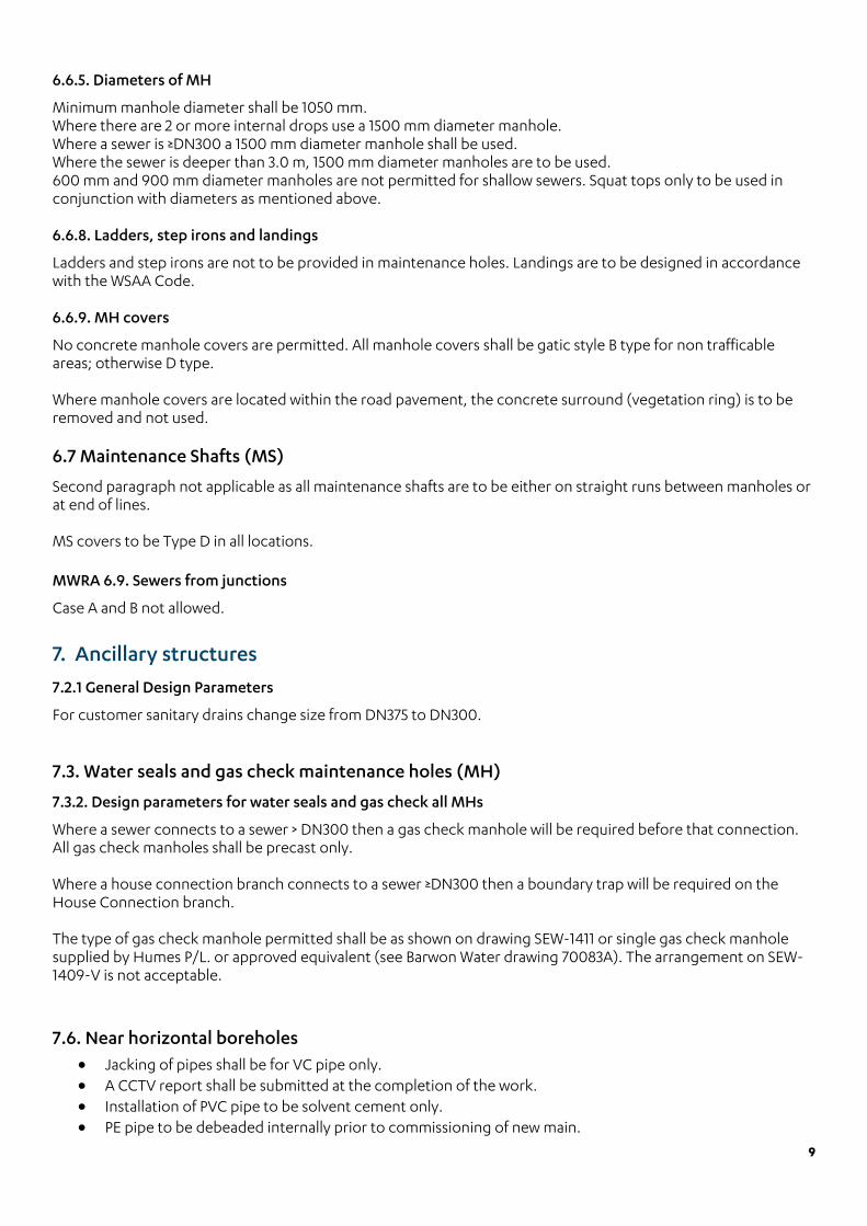
Minimum manhole diameter shall be 1050 mm. Where there are 2 or more internal drops use a 1500 mm diameter manhole. Where a sewer is ≥DN300 a 1500 mm diameter manhole shall be used. Where the sewer is deeper than 3.0 m, 1500 mm diameter manholes are to be used. 600 mm and 900 mm diameter manholes are not permitted for shallow sewers. Squat tops only to be used in conjunction with diameters as mentioned above. 6.6.8. Ladders, step irons and landings
Ladders and step irons are not to be provided in maintenance holes. Landings are to be designed in accordance with the WSAA Code. 6.6.9. MH covers
No concrete manhole covers are permitted. All manhole covers shall be gatic style B type for non trafficable areas; otherwise D type. Where manhole covers are located within the road pavement, the concrete surround (vegetation ring) is to be removed and not used. 6.7 Maintenance Shafts (MS)
Second paragraph not applicable as all maintenance shafts are to be either on straight runs between manholes or at end of lines. MS covers to be Type D in all locations. MWRA 6.9. Sewers from junctions
Case A and B not allowed.
7. Ancillary structures
7.2.1 General Design Parameters
For customer sanitary drains change size from DN375 to DN300. 7.3. Water seals and gas check maintenance holes (MH)
7.3.2. Design parameters for water seals and gas check all MHs
Where a sewer connects to a sewer > DN300 then a gas check manhole will be required before that connection. All gas check manholes shall be precast only. Where a house connection branch connects to a sewer ≥DN300 then a boundary trap will be required on the House Connection branch. The type of gas check manhole permitted shall be as shown on drawing SEW-1411 or single gas check manhole supplied by Humes P/L. or approved equivalent (see Barwon Water drawing 70083A). The arrangement on SEW-1409-V is not acceptable. 7.6. Near horizontal boreholes
• Jacking of pipes shall be for VC pipe only. • A CCTV report shall be submitted at the completion of the work. • Installation of PVC pipe to be solvent cement only. • PE pipe to be debeaded internally prior to commissioning of new main.

10
8. Structural design
8.8. Pipe cover
Drawing 1201v shall be used with minimum cover of 750mm to sewer. 8.10. Bulkheads and trenchstops
Concrete bulkheads shall be used where the grade of the sewer is equal to or steeper than 1 in 10. The grade of the pipe shall be equal to the longitudinal spacing of the concrete bulkheads - e.g. 1 in 8 grade gives a concrete bulkhead spacing of 8 metres. Where the grade is steeper than 1 in 3.5, concrete bulkheads will be required on the same basis with continuous concrete encasing of the sewer. Where the sewer is designed at a grade steeper than a 1 in 2, special design requirements may be imposed. 9. Design review and drawings
9.2 Design drawings
(t) Any other relevant information
• all allotments to be serviced • street names • Allotment and/or Street numbers • Extent of work. • Location of any existing other services • Obstructions (re trees, structures etc). • Symbols showing location of valves fire plugs and reducers etc. • Pipe size and material • Easements • All storm water drains with details of size • North point • Scale • Drawing number • Drawing revision number • One copy of each drawing is to be submitted along with road construction drawings, for checking and
subsequent acceptance.
9.3 Drafting standards The following tables shall be used instead of the MRWA standards. Figure 9.1 below displays the legend, title block and other standard notes to be displayed on the design. H G A B C D E F
Figure 9.1 Layout sheet for designs
11
A)
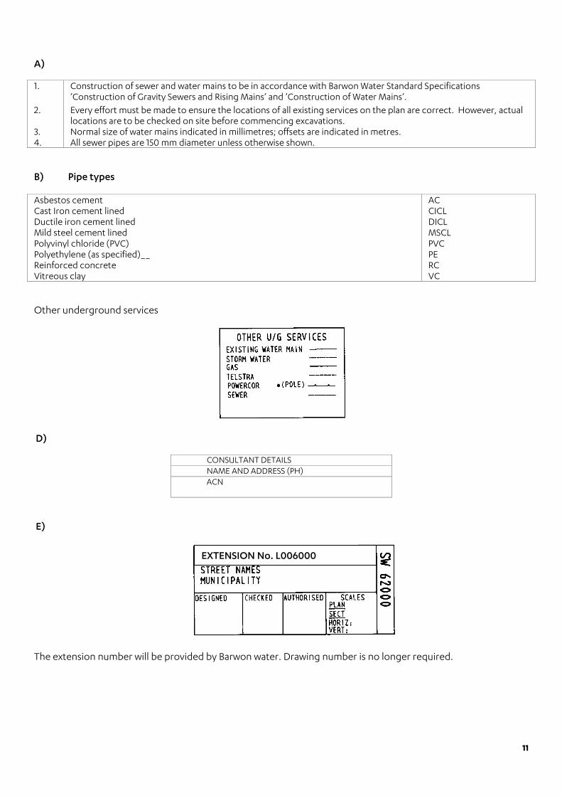
1. Construction of sewer and water mains to be in accordance with Barwon Water Standard Specifications ’Construction of Gravity Sewers and Rising Mains’ and ’Construction of Water Mains’.
2. Every effort must be made to ensure the locations of all existing services on the plan are correct. However, actual locations are to be checked on site before commencing excavations.
3. Normal size of water mains indicated in millimetres; offsets are indicated in metres. 4. All sewer pipes are 150 mm diameter unless otherwise shown.
B) Pipe types Asbestos cement AC Cast Iron cement lined CICL Ductile iron cement lined DICL Mild steel cement lined MSCL Polyvinyl chloride (PVC) PVC Polyethylene (as specified)__ PE Reinforced concrete RC Vitreous clay VC
Other underground services
D)
CONSULTANT DETAILS NAME AND ADDRESS (PH) ACN
E)
The extension number will be provided by Barwon water. Drawing number is no longer required.
EXTENSION No. L006000
12
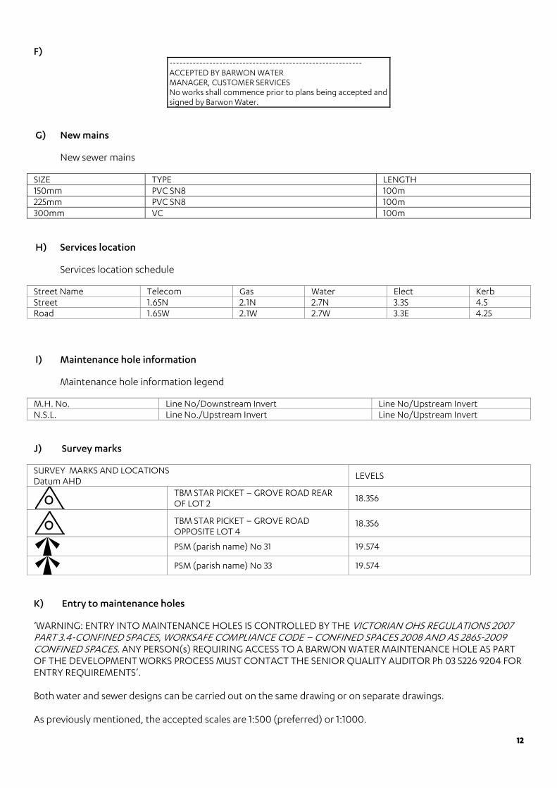
F) ---------------------------------------------------------- ACCEPTED BY BARWON WATER MANAGER, CUSTOMER SERVICES No works shall commence prior to plans being accepted and signed by Barwon Water.
G) New mains
New sewer mains
SIZE TYPE LENGTH 150mm PVC SN8 100m 225mm PVC SN8 100m 300mm VC 100m
H) Services location
Services location schedule
Street Name Telecom Gas Water Elect Kerb Street 1.65N 2.1N 2.7N 3.3S 4.5 Road 1.65W 2.1W 2.7W 3.3E 4.25
I) Maintenance hole information
Maintenance hole information legend
M.H. No. Line No/Downstream Invert Line No/Upstream Invert N.S.L. Line No./Upstream Invert Line No/Upstream Invert
J) Survey marks
SURVEY MARKS AND LOCATIONS Datum AHD
LEVELS
TBM STAR PICKET – GROVE ROAD REAR OF LOT 2
18.356
TBM STAR PICKET – GROVE ROAD OPPOSITE LOT 4
18.356
PSM (parish name) No 31 19.574
PSM (parish name) No 33 19.574
K) Entry to maintenance holes
‘WARNING: ENTRY INTO MAINTENANCE HOLES IS CONTROLLED BY THE VICTORIAN OHS REGULATIONS 2007 PART 3.4-CONFINED SPACES, WORKSAFE COMPLIANCE CODE – CONFINED SPACES 2008 AND AS 2865-2009 CONFINED SPACES. ANY PERSON(s) REQUIRING ACCESS TO A BARWON WATER MAINTENANCE HOLE AS PART OF THE DEVELOPMENT WORKS PROCESS MUST CONTACT THE SENIOR QUALITY AUDITOR Ph 03 5226 9204 FOR ENTRY REQUIREMENTS’. Both water and sewer designs can be carried out on the same drawing or on separate drawings. As previously mentioned, the accepted scales are 1:500 (preferred) or 1:1000.
13
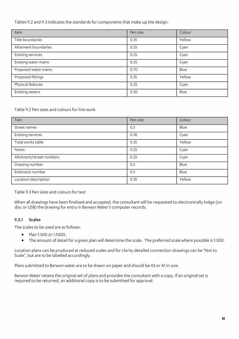
Tables 9.2 and 9.3 indicates the standards for components that make up the design. Item Pen size Colour
Title boundaries 0.35 Yellow
Allotment boundaries 0.25 Cyan
Existing services 0.25 Cyan
Existing water mains 0.25 Cyan
Proposed water mains 0.70 Blue
Proposed fittings 0.35 Yellow
Physical features 0.25 Cyan
Existing sewers 0.50 Blue
Table 9.2 Pen sizes and colours for line work Text Pen size Colour
Street names 0.5 Blue
Existing services 0.18 Cyan
Total works table 0.35 Yellow
Notes 0.25 Cyan
Allotment/street numbers 0.25 Cyan
Drawing number 0.5 Blue
Extension number 0.5 Blue
Location description 0.35 Yellow
Table 9.3 Pen sizes and colours for text When all drawings have been finalised and accepted, the consultant will be requested to electronically lodge (on disc or USB) the drawing for entry in Barwon Water's computer records.
9.3.1 Scales
The scales to be used are as follows:
• Plan 1:500 or 1:1000. • The amount of detail for a given plan will determine the scale. The preferred scale where possible is 1:500.
Location plans can be produced at reduced scales and for clarity detailed connection drawings can be "Not to Scale", but are to be labelled accordingly. Plans submitted to Barwon water are to be drawn on paper and should be A3 or A1 in size. Barwon Water retains the original set of plans and provides the consultant with a copy. If an original set is required to be returned, an additional copy is to be submitted for approval.

14
Part 2: Products and materials All materials used must be ’approved’ by Barwon Water. Further information on approved products is available by contacting Barwon Water. All materials used in Barwon Water’s system must have WSAA appraisal. Note: Not all WSAA appraised materials are approved for use in Barwon Water’s system.
15
Part 3: Construction
12 Quality
In addition, it is recommended that clauses 2.3 and 4 of Barwon Water’s Land Development Manual (policy document) are referred to. 13.5.3. Disused / redundant sewers
Where a sewer is no longer required, it shall be:
• Purchased by the land owner, and: o removed if less than 1.5 metres deep o grouted if equal to or greater than 1.5 metres deep.
14 Products and materials
Barwon Water’s approved product list is available on its website, under the business tab, as follows
• 150/225 mm PVC sewer approved to a maximum depth of 5.0 metres. • SewerPro permitted up to sizes DN300 mm and a maximum depth of 6.0 metres. • Any sewer DN300 mm and above to be VC, unless equivalent approved by Barwon Water. • Any sewer greater than 5.0 m deep to be VC, unless equivalent approved by Barwon Water.
17.2.2 Methods of deflection
Pipe curvature may only be achieved by cumulative deflection at pipe joints. Design shall specify the pipe that is proposed to be used. Manufacturer’s recommended maximum joint deflection for those pipes shall be provided with the design.
17.2.4 Vertical curves
Only manufactured inspection bends are to be used for internal drop structures within manholes. The cutting of an opening on standard 90 degree bends is not acceptable.
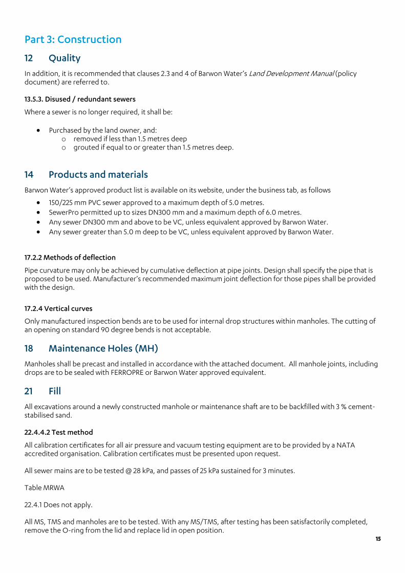
18 Maintenance Holes (MH)
Manholes shall be precast and installed in accordance with the attached document. All manhole joints, including drops are to be sealed with FERROPRE or Barwon Water approved equivalent.
21 Fill
All excavations around a newly constructed manhole or maintenance shaft are to be backfilled with 3 % cement-stabilised sand. 22.4.4.2 Test method
All calibration certificates for all air pressure and vacuum testing equipment are to be provided by a NATA accredited organisation. Calibration certificates must be presented upon request. All sewer mains are to be tested @ 28 kPa, and passes of 25 kPa sustained for 3 minutes. Table MRWA 22.4.1 Does not apply. All MS, TMS and manholes are to be tested. With any MS/TMS, after testing has been satisfactorily completed, remove the O-ring from the lid and replace lid in open position.
16
MH, MS and TMS test commences at 35 kPa, and passes if 28 kPa sustained for three minutes. Table 22.6 ’Minimum test times for concrete manholes’ does not apply. All test plugs and any other plug required to isolate a Barwon Water sewer main is to be inflatable type or any other type approved by Barwon Water. Any test plug is to be tommed and also secured at the surface. For further details on this requirement and for a copy of Barwon Water’s procedure for installation of plugs, please contact Development Services.
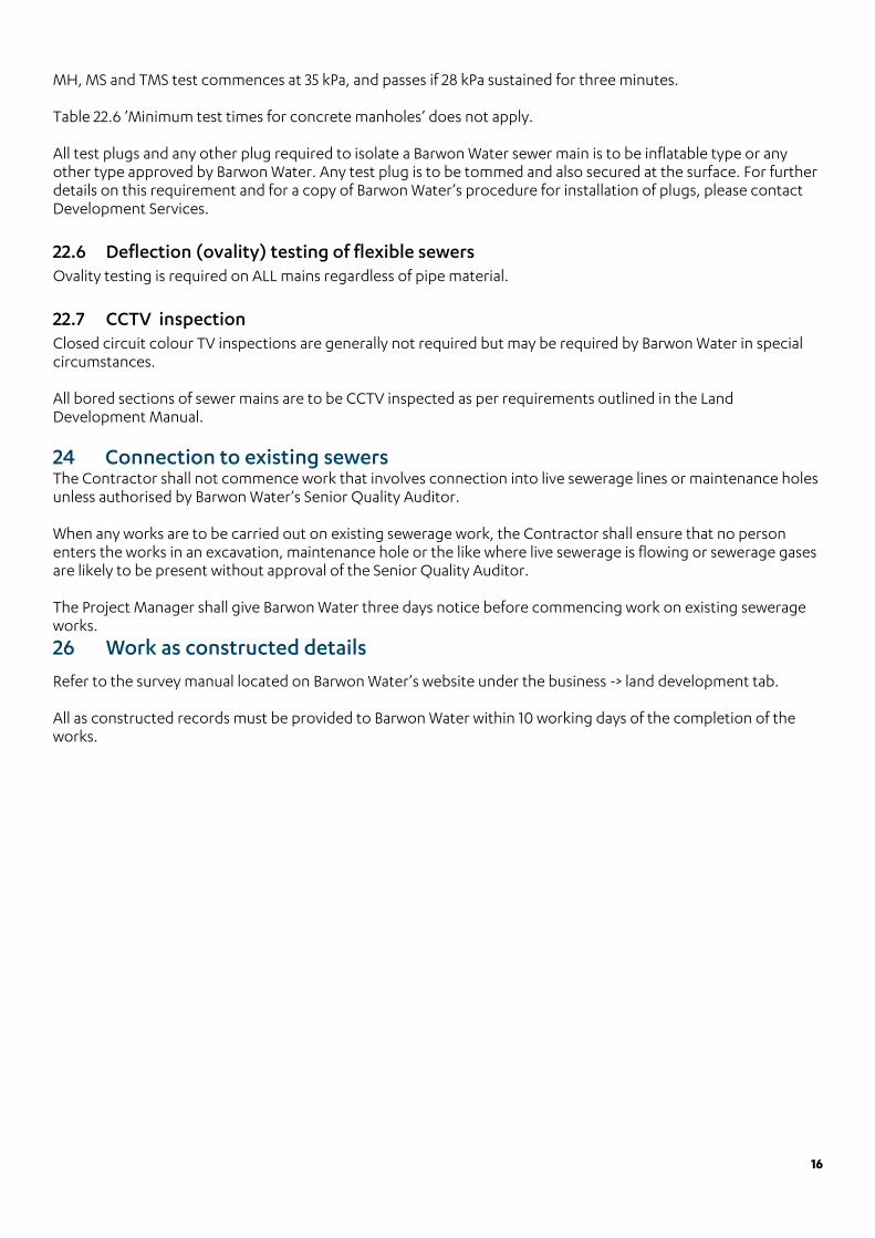
22.6 Deflection (ovality) testing of flexible sewers Ovality testing is required on ALL mains regardless of pipe material.
22.7 CCTV inspection Closed circuit colour TV inspections are generally not required but may be required by Barwon Water in special circumstances. All bored sections of sewer mains are to be CCTV inspected as per requirements outlined in the Land Development Manual.
24 Connection to existing sewers The Contractor shall not commence work that involves connection into live sewerage lines or maintenance holes unless authorised by Barwon Water’s Senior Quality Auditor. When any works are to be carried out on existing sewerage work, the Contractor shall ensure that no person enters the works in an excavation, maintenance hole or the like where live sewerage is flowing or sewerage gases are likely to be present without approval of the Senior Quality Auditor. The Project Manager shall give Barwon Water three days notice before commencing work on existing sewerage works.
26 Work as constructed details
Refer to the survey manual located on Barwon Water’s website under the business -> land development tab. All as constructed records must be provided to Barwon Water within 10 working days of the completion of the works.

17
Part 4: Standard drawings
Drawing number Title/ Comments
70083A Maintenance hole chamber detail Single gascheck manhole only applicable
70095 House connection branch details Type Spec. A, MS, TMS, applicable
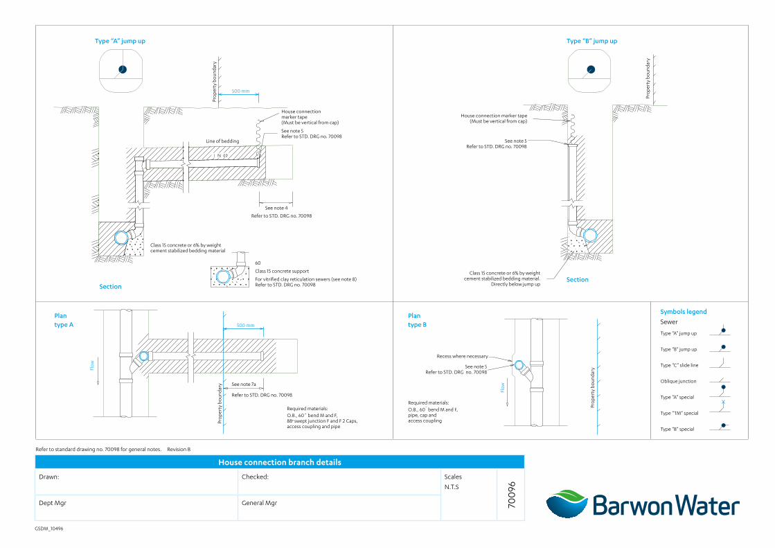
70096 House connection branch details Type A & B
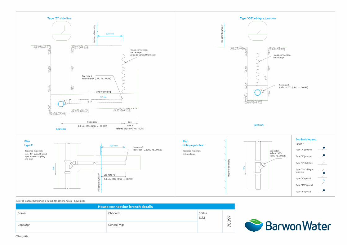
70097 House connection branch details Type C & OB
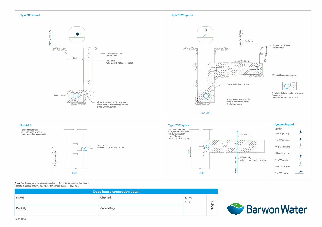
70116 House connection branch details Deep HC Details – Type B & Spec. TM
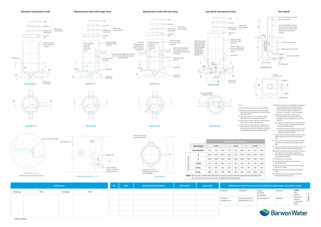
Maintenance hole chamber and vent details for waste water reticulation mains
PDMS No.: Designed: Drawn: 05/10/04 B. Macauley
Checked: Scales: PlanSectionHorizontalVerticalScale for A1 Sheet
700
83 -
A
Contract/ Quotation No:
Drawing discipline:MW sheet no. 1 of 1
Senior Engineer: Manager:
References No. Date Amendment description Revised by Approved
Drawing Title Drawing Title
Dimensions in millimetres
Vent height 6000 9000 12000
Vent diameter 150 225 300 150 225 300 150 225 300
Sym
bols
as
sho
wn
A 1000 1000 1300 1100 1100 1300 1200 1200 1300
B 1000 1000 1300 1250 1250 1300 1750 1750 1750
C (dia) 150 225 300 150 225 300 150 225 300
D min. 150 150 150 150 150 150 150 150 150
E min. 400 450 450 600 620 620 800 800 820
Note: Vents to be coated internally with an epoxy coal tar enamel and painted externally with zinc rich primer and two coats of an approved finishing paint.
GSDM_10496
Notes
1. All concrete to be class 25 to A.S. 3600 Standard
2. Maintenance hole to be centrally placed around intersection point of wastewater centrelines unless otherwise specified.
3. UPVC pipes to be S.E.H, in accordance with A.S. 1260 UPVC pipes for wastewater applications.
4. Joints in vertical UPVC drop pipes to be pushed fit. (No solvent or rubber rings to be used)
5. UPVC drop pipe clamps shall be provided at each UPVC socket at a maximum spacing of 1 metre. No clamps are required for UPVC pipe drops less than 1 metre between invert levels. (Refer to detail)
6. a) Covers and surround type shall be in accordance with long sections or as directed by (Barwon Water). Generally Heavy Gatic type kerb and covers shall be provided in roadways and driveways - Gatic type “D” covers elsewhere.
b) Maintenance hole within road reserves/footpaths shall be constructed with at least two make up rings to facilitate future raising or lowering.
c) i. Inspection chamber covers are to be graded to suit natural surface or footpath/road levels as directed by (Barwon Water).
ii. To achieve the desired slope surround is to be seated on appropriately shaped epoxy to the satisfaction of (Barwon Water)
7. Unless otherwise directed by Barwon Water, covers shall be located directly above the downstream pipes.
8. In lieu of 100 to 100 UPVC drop bend, 100 UPVC 88 deg. Bend with capped rear access bend, may be used.
9. Inspection chamber drops for wastewater mains of 300 mm and above will be detailed separately.
10. Where future extensions from inspection chambers are designated on the drawings, appropriate channel(s) and capped pipes(s) will be provided as directed by Barwon Water.
11. All dimensions in millimeters
12. See installation guide for precast concrete maintenance hole.
13. Squat top can only be used in maintenance holes, less than 1.5 m deep
14. Taper top only to be used as directed by Barwon Water.
15. Maintenance holes to be tested as per Barwon Water developer works process.
Joint detail (not to scale)
(Converter slab to make ring to surround) Detail drop pipe clamp (not to scale) Standard drawing
As per manufacturers detail
UPVC drop pipe60
nom.
2 holes 40 MAX. deep to suit M10 S.S masonry anchors
Galvanised M.S or P.V.C. coated drop pipe clamp for precast manholes
M10 bolt and lock nut (supplied with clamp)
24 mm MIN
75
585 mm x 480 mm precast concrete baffle with A5 1304 F 82 mesh central
Cover CoverCover
CoverM.S vent made from 5 mm plate
Mastic seal all round
5 mm TH steel sleeve I.D to suit D.D of Vent sleeve to be coated externally and internally as vent except part in contact with concrete.
100 mm cover all round
Weld cage out of F 82 mesh
V.C pipe to manhole
Flexible jointC x 90 V.C bend
1 in 10
C
B12
00
D m
in.
E m
in.
Leav
e o
utsi
de o
f sl
eeve
unc
oat
ed
Surround SurroundSurround
Surround
Make up ring (as required)
Make up ring (as required)
Make up ring (as required)
Make up ring (as required)
Converter slab
Converter slab
Converter slab
Converter slab
Shaft starter
C E
D F J
C E
D F J
Section D-D
Standard maintenance hole Maintenance hole with single drop Maintenance hole with two drop Gas check maintenance hole Vent detail
Section F-F Section J-J Section B-B
Plan
KK
Section C-C Section E-E Section H-H Section A-A
1100 I.D concrete shafts with rubber ring joints
1100 I.D concrete shafts with rubber ring joints
1100 I.D concrete shafts with rubber ring jointsUPVC drop bend
225 to 150 150 to 150 100 to 100 (F+F)
UPVC drop bend 225 to 150 150 to 150 100 to 100 (F+F)
Hole core drilled in precast component and
filled around pipe epoxy mortar
UPVC pipe clamp, see note 5.
UPVC pipe clamp, see note 5.
Shaft starterShaft starter
Shaft starter
90 deg. M-F UPVC bend
90 deg. M-F UPVC bend
600 long V.C or UPVC pipe20
0
Flow
130
R150 R150
R400
3 mm Clearance
100 130
50
75
100
min
“d”
50
1 in 9
1 in 9 1 in 91 in 9 1 in 9
150
100
50
Spigot and socket adaptor for V.C pipes or 600 mm short UPVC pipe directly
out of drop bend
50
150
50 100
600 long V.C. or UPVC pipe
Refer note 6 and joint detail
Refer note 6 and joint detail
Refer note 6 and joint detail
Refer note 6 and joint detail
1 in 9 1 in 9
1 in 9 1 in 9
150
100
50
H H
Spigot and socket adaptor for V.C pipes or 600 mm short UPVC pipe directly out of drop bend.
540 mm x 400 mm precast concrete cover with A5 1304 F82 mesh central (neoprene gasket placed under cover) hot-dip galvanised r10 handle welded to mash
B B
Cover slab and baffle omitted for clarity
A
100 mm cover all round
F 82 Mesh
A
1100 I.D concrete shafts with rubber ring joints
50
Flexible joint
Section K-K
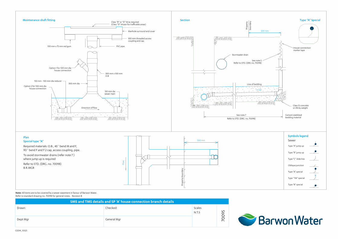
SMS and TMS details and SP ‘A’ house connection branch details
Drawn: Checked: Scales
N.T.S
700
95Dept Mgr General Mgr
GSDM_10525
Maintenance shaft fitting Section Type “A” Special
PlanSpecial type “A”
Required materials: O.B., 45˚ bend M and F, 90˚ bend F and F 2 cap, access coupling, pipe.
To avoid stormwater drains (refer note 7 ) where jump up is required
Refer to STD. (DRG. no. 70098) B.R.MGR
Type “A” jump up
Type “B” jump up
Type “C” slide line
Oblique junction
Type “A” special
Type “TM” special
Type “B” special
Pro
pert
y
boun
dary
Pro
pert
y bo
unda
ry
Symbols legend
Sewer
Note: All items are to be covered by a sewer easement in favour of Barwon Water. Refer to standard drawing no. 70098 for general notes. Revision B
500 mm
500 mm
Flo
w
100 mm x 75 mm red gum
Option 1 for 100 mm dia house connection
Option 2 for 100 mm dia house connection
150 mm - 100 mm dia reducer300 mm dia
300 mm x 100 mm O.B
PVC pipe
300 mm threaded access coupling and cap
Stormwater drain
Line of bedding
See note 5Refer to STD. (DRG no. 70098)
See note 7
Refer to STD. (DRG. no. 70098)
Class 15 concrete or 6% by weight
Cement stabilized bedding material
House connection marker tape
Manhole surround and cover
Class “B” or “D” lid as required(Class “D” shown for trafficable areas)
150 mm dia sewer main
Direction of flow
1 in 60
House connection branch details
Drawn: Checked: Scales
N.T.S
700
96Dept Mgr General Mgr
GSDM_10496
Type “A” jump up Type “B” jump up
SectionSection
Plan type A
Plan type B
500 mm
500 mm
See note 7a
Refer to STD. DRG no. 70098
Required materials: O.B., 60˚ bend M and F, 88 swept junction F and F 2 Caps, access coupling and pipe
Required materials:O.B., 60˚ bend M and F, pipe, cap and access coupling
House connection marker tape (Must be vertical from cap)
Refer to STD. DRG no. 70098
60
Class 15 concrete support
For vitrified clay reticulation sewers (see note 8) Refer to STD. DRG no. 70098
See note 5 Refer to STD. DRG no. 70098
House connection marker tape (Must be vertical from cap)
Class 15 concrete or 6% by weight cement stabilized bedding material.
Directly below jump up
Type “A” jump up
Type “B” jump up
Type “C” slide line
Oblique junction
Type “A” special
Type “TM” special
Type “B” special
Recess where necessary
Class 15 concrete or 6% by weight cement stabilized bedding material
Line of bedding
See note 4 Pr
ope
rty
boun
dary
Pro
pert
y bo
unda
ry
Pro
pert
y bo
unda
ry
Flo
w
Flo
w
Pro
pert
y bo
unda
ry
See note 5 Refer to STD. DRG no. 70098
See note 5 Refer to STD. DRG no. 70098
Symbols legend
Sewer
Refer to standard drawing no. 70098 for general notes. Revision B
House connection branch details
Drawn: Checked: Scales
N.T.S
700
97Dept Mgr General Mgr
GSDM_10496
Type “C” slide line Type “OB” oblique junction
SectionSection
Plan type C
Plan oblique junction
500 mm
500 mm
Required materials:O.B., 45˚ M and F bend, pipe, access coupling and pipe
Required materials:O.B. and cap
See note 5 Refer to STD (DRG. no. 70098)
House connection marker tape (Must be vertical from cap)
Refer to STD. (DRG no. 70098)
Type “A” jump up
Type “B” jump up
Type “C” slide line
Type “OB” oblique junction
Type “A” special
Type “TM” special
Type “B” special
See note 5 Refer to STD. (DRG. no. 70098)
1 in 60
Line of bedding
See
note 4
See note 7
Refer to STD. (DRG. no. 70098)
See note 7a
Refer to STD. (DRG. no. 70098)
See note 5 Refer to STD. (DRG no. 70098)
Pro
pert
y bo
unda
ry
Pro
pert
y bo
unda
ry
Pro
pert
y bo
unda
ry
Pro
pert
y bo
unda
ry
Flo
w
Flo
w
Symbols legend
Sewer
Refer to standard drawing no. 70098 for general notes Revision B
See note 5 Refer to STD (DRG. no. 70098)
House connection marker tape
Deep house connection detail
Drawn: Checked: Scales
N.T.S
7011
6Dept Mgr General Mgr
GSDM_10496
Type “B” special
Special B
Type “TM” special
Type “TM” special
Section
PlanPlan
500 mm
Line of bedding
See attached DRG. 70116
House connection marker tape
House connection marker tape
For vitrified clay reticulation sewers (See note 8) Refer to STD. (DRG no. 70098)
60 class 15 concrete support
See note 5 Refer to STD. (DRG No. 70098)
Pro
pert
y bo
unda
ry
Pro
pert
y bo
unda
ry
Pro
pert
y bo
unda
ry
Flo
w
700
mm
Class 15 concrete or 6% by weight cement stabilized bedding material. Directly below jump up
Side support
Trench
Type “A” jump up
Type “B” jump up
Type “C” slide line
Oblique junction
Type “A” special
Type “TM” special
Type “B” special
Symbols legend
Sewer
Note: Any house connection branches below 3 m to be constructed as shown Refer to standard drawing no. 70098 for general notes. Revision B
Bedding
Overlay
See note 5Refer to STD. (DRG no. 70098)
Required materials:O.B., 60˚ bend M and F, pipe, cap and access coupling
Required materials:O.B., 60˚ bend M and F, 88˚ swept junction F and F 2 caps, access coupling and pipe.
Pro
pert
y bo
unda
ry
See note 7a
Refer to STD. (DRG no. 70098)
500 mm
Class 15 concrete or 6% by weight cement stabilized bedding material