Superstrut Metal Framing System - The Reynolds Company · PDF fileSuperstrut channel and...
116
Superstrut ® Metal Framing System In this section... Superstrut ® Metal Framing System Overview ................................................................... B-106–B-109 Channels ................................................................... B-110–B-111 Threaded Products and Hardware .............................. B-112–B-117 Fittings and Brackets ................................................. B-118–B-125 Concrete Inserts ........................................................ B-126–B-127 Beam Clamps ............................................................ B-128–B-135 Pipe Straps, Conduit Clamps and Hangers ................. B-136–B-182 Surface Raceway and Lighting Systems..................... B-183–B-187 Slotted Angle Metal Framing ...................................... B-188–B-189 Special Metals and Finishes ....................................... B-190–B-198 Technical Information ................................................ B-199–B-220
Transcript of Superstrut Metal Framing System - The Reynolds Company · PDF fileSuperstrut channel and...

Superstrut ® Metal Framing System
In this section...
Superstrut® Metal Framing System
Overview ................................................................... B-106–B-109
Channels ................................................................... B-110–B-111
Threaded Products and Hardware.............................. B-112–B-117
Fittings and Brackets ................................................. B-118–B-125
Concrete Inserts ........................................................ B-126–B-127
Beam Clamps ............................................................ B-128–B-135
Pipe Straps, Conduit Clamps and Hangers ................. B-136–B-182
Surface Raceway and Lighting Systems..................... B-183–B-187
Slotted Angle Metal Framing...................................... B-188–B-189
Special Metals and Finishes....................................... B-190–B-198
Technical Information ................................................ B-199–B-220

www.tnb.comUnited States
Tel: 901.252.8000800.816.7809
Fax: 901.252.1354
Technical Services
Tel: 888.862.3289B-106
Met
al F
ram
ing
& C
able
Tra
y —
Sup
erst
rut®
Met
al F
ram
ing
Syst
em
Overview
Thomas & Betts is proud to introduce the new and improvedTrivalent GoldGalv® finish. GoldGalv® finish is a combinationof .5 mils electro-plated zinc and a gold Trivalent Chromium finish.
New Trivalent GoldGalv® Finish Is RoHS Compliant
Gold Trivalent Chromium Finish — The new GoldGalv® finish features a Trivalent Chromium formulation that provides all the features and protection of Hexavalent Chromium (CR VI) without the use of this chemical compound. Hexavalent Chromium is restricted by some standards such as the European Union directive on the restriction of the use of certain hazardous substances in electrical and electronic equipment (RoHS).
RoHS Compliant — One great feature for the new Trivalent Chromium formulation is RoHS compliance. Because Hexavalent Chromium is a substance that is restricted by RoHS, moving away from a Hexavalent formulation to the new Trivalent formulation will make the performance of GoldGalv® coating available to customers affected by RoHS and other standards like RoHS around the world.
Trivalent GoldGalv® Finish Is OSHA Safe — The Hexavalent formulation of the GoldGalv® finish is safe with regard to the revised 2006 OSHA standard. This new Trivalent formulation of the GoldGalv® finish does not contain any Hexavalent Chromium and therefore does not fall under the scope of the OSHA standard at all. As a result, the new Trivalent GoldGalv® finish, just like the Hexavalent GoldGalv® finish, is OSHA compliant.
ASTM B633 Specification — The improved GoldGalv® finish is applied in compliance with ASTM B633 coating, the same standard as used previously. This standard outlines electro-deposited coatings of zinc on steel.

United States
Tel: 901.252.8000800.816.7809
Fax: 901.252.1354
Technical Services
Tel: 888.862.3289www.tnb.com
B-107
Overview
GoldGalv ®
The standard GoldGalv® finish is made up of a multi-step zinc electrogalvanizing process. The Trivalent Chromium finish is applied over the zinc, producing a chemically bonded non-porous barrier for protection from moisture and air. The .5 mil electro-plated zinc and gold Trivalent Chromium finish provides all of the features and protection of Hexavalent Chromium without the use of the chemical.
Formed HotRolled Steel
Electro-PlatedZinc Coating
Yellow Trivalent Conversion Coat
Finishes
Sa
lt S
pra
y H
ou
rs
Metal Framing Channel FinishCorrosion-Resistant Testing, ASTM B117
IndustryEnamelGreen
EpoxyGreen
IndustryPre-Galvanized
G90
EG-SilverGalv®
TrivalentGoldGalv®
1100
1000
900
800
700
600
500
400
300
200
100
0
Tank 1
Tank 9
Tank 2
Tank 10
Tank 3
Tank 11
Tank 4
Tank 12
Tank 5 Tank 6 Tank 7 Tank 8
“Soak Degreasing” “Electro Cleaner” “Rinse” “Sulfuric Acid Bath”
Chemical solution removes bulk of oil and grease buildup.
The metal isnegatively chargedto remove minute surface particles.
Live, clear water rinse.
Prepares the metal by etching the surface for the
zinc application.
“Rinse” “Zinc Tank” “Rinse” “Rinse”
Live, clear water rinse.
Electrically applies the zinc metal
coating.
Chemically treated rinse water.
Live, clear water rinse.
“Rinse” “Chromium Dip” “Rinse” “Dryer”
Live, clear water rinse.
A yellow trivalent conversion coat
is applied tothe zinc.
Live, clear water rinse.
Hot air is forced around strut
until dry.
Metal Fram
ing & Cable Tray —
Superstrut® M
etal Framing System
www.tnb.comUnited States
Tel: 901.252.8000800.816.7809
Fax: 901.252.1354
Technical Services
Tel: 888.862.3289B-108
Met
al F
ram
ing
& C
able
Tra
y —
Sup
erst
rut®
Met
al F
ram
ing
Syst
em
Overview
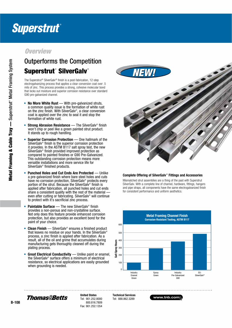
No More White Rust — With pre-galvanized struts,a common quality issue is the formation of white ruston the zinc finish. With SilverGalv®, a clear conversion coat is applied over the zinc to seal it and stop the formation of white rust.
Strong Abrasion Resistance — The SilverGalv® finish won’t chip or peel like a green painted strut product.It stands up to rough handling.
Superior Corrosion Protection — One hallmark of the SilverGalv® finish is the superior corrosion protection it provides. In the ASTM B117 salt spray test, the new SilverGalv® finish provided improved protection as compared to painted finishes or G90 Pre-Galvanized.This outstanding corrosion protection means more versatile installations and more service life forSilverGalv® finished products.
Punched Holes and Cut Ends Are Protected — Unlike a pre-galvanized finish where bare steel holes and cuts have no corrosion protection, SilverGalv® protects every portion of the strut. Because the SilverGalv® finish is applied after fabrication, all punched holes and cut ends share a consistent quality with the rest of the material — even after cutting or fabricating. SilverGalv® will continue to protect with it’s sacrificial zinc process.
Paintable Surface — The new SilverGalv® finish provides a non-porous and non-crystalline surface. Not only does this feature provide enhanced corrosion protection, but also provides an excellent bond for the paint of your choice.
Clean Finish — SilverGalv® ensures a finished product that leaves no residue on your hands. In the SilverGalv®
process, a zinc finish is applied after fabrication. As a result, all of the oil and grime that accumulates during manufacturing gets thoroughly cleaned off during the plating process.
Great Electrical Conductivity — Unlike paint or enamel, the SilverGalv® surface offers a minimum of electrical resistance, so electrical applications are easily grounded when grounding is needed.
Complete Offering of SilverGalv® Fittings and Accessories
Mismatched strut assemblies are a thing of the past with Superstrut SilverGalv. With a complete line of channel, hardware, fittings, hangersand pipe straps, all components have the same electrogalvanized finishfor consistent performance and uniform aesthetics.
Superstrut® SilverGalv®
Outperforms the Competition
Sa
lt S
pra
y H
ou
rs
Metal Framing Channel FinishCorrosion-Resistant Testing, ASTM B117
IndustryEnamelGreen
EpoxyGreen
IndustryPre-Galvanized
G90
EG-SilverGalv®
600
500
400
300
200
100
0
The Superstrut® SilverGalv® finish is a post-fabrication, 12-step electrogalvanizing process that applies a clear conversion coat over .5 mils of zinc. This process provides a strong, cohesive molecular bondthat locks out moisture and superior corrosion resistance over standard G90 pre-galvanized channel.
NEW!NEW!
United States
Tel: 901.252.8000800.816.7809
Fax: 901.252.1354
Technical Services
Tel: 888.862.3289www.tnb.com
B-109
Metal Fram
ing & Cable Tray —
Superstrut® M
etal Framing System
Overview
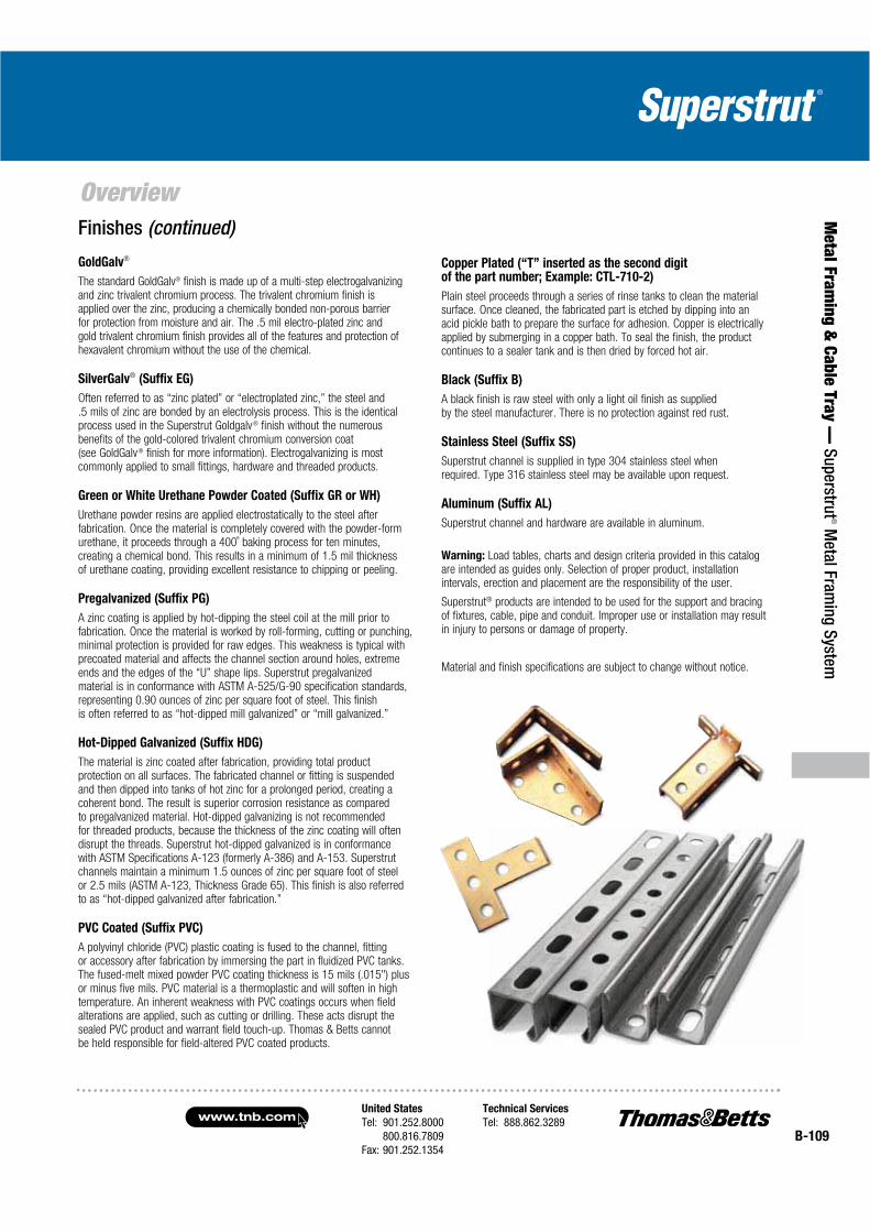
Copper Plated (“T” inserted as the second digit of the part number; Example: CTL-710-2)
Plain steel proceeds through a series of rinse tanks to clean the material surface. Once cleaned, the fabricated part is etched by dipping into an acid pickle bath to prepare the surface for adhesion. Copper is electrically applied by submerging in a copper bath. To seal the finish, the product continues to a sealer tank and is then dried by forced hot air.
Black (Suffix B)
A black finish is raw steel with only a light oil finish as supplied by the steel manufacturer. There is no protection against red rust.
Stainless Steel (Suffix SS)
Superstrut channel is supplied in type 304 stainless steel when required. Type 316 stainless steel may be available upon request.
Aluminum (Suffix AL)
Superstrut channel and hardware are available in aluminum.
Warning: Load tables, charts and design criteria provided in this catalogare intended as guides only. Selection of proper product, installation intervals, erection and placement are the responsibility of the user.
Superstrut® products are intended to be used for the support and bracing of fixtures, cable, pipe and conduit. Improper use or installation may result in injury to persons or damage of property.
Material and finish specifications are subject to change without notice.
GoldGalv®
The standard GoldGalv® finish is made up of a multi-step electrogalvanizing and zinc trivalent chromium process. The trivalent chromium finish is applied over the zinc, producing a chemically bonded non-porous barrier for protection from moisture and air. The .5 mil electro-plated zinc and gold trivalent chromium finish provides all of the features and protection of hexavalent chromium without the use of the chemical.
SilverGalv® (Suffix EG)
Often referred to as “zinc plated” or “electroplated zinc,” the steel and .5 mils of zinc are bonded by an electrolysis process. This is the identical process used in the Superstrut Goldgalv® finish without the numerous benefits of the gold-colored trivalent chromium conversion coat(see GoldGalv® finish for more information). Electrogalvanizing is most commonly applied to small fittings, hardware and threaded products.
Green or White Urethane Powder Coated (Suffix GR or WH)
Urethane powder resins are applied electrostatically to the steel after fabrication. Once the material is completely covered with the powder-form urethane, it proceeds through a 400˚ baking process for ten minutes, creating a chemical bond. This results in a minimum of 1.5 mil thickness of urethane coating, providing excellent resistance to chipping or peeling.
Pregalvanized (Suffix PG)
A zinc coating is applied by hot-dipping the steel coil at the mill prior to fabrication. Once the material is worked by roll-forming, cutting or punching, minimal protection is provided for raw edges. This weakness is typical with precoated material and affects the channel section around holes, extreme ends and the edges of the “U” shape lips. Superstrut pregalvanized material is in conformance with ASTM A-525/G-90 specification standards, representing 0.90 ounces of zinc per square foot of steel. This finishis often referred to as “hot-dipped mill galvanized” or “mill galvanized.”
Hot-Dipped Galvanized (Suffix HDG)
The material is zinc coated after fabrication, providing total product protection on all surfaces. The fabricated channel or fitting is suspended and then dipped into tanks of hot zinc for a prolonged period, creating a coherent bond. The result is superior corrosion resistance as compared to pregalvanized material. Hot-dipped galvanizing is not recommended for threaded products, because the thickness of the zinc coating will often disrupt the threads. Superstrut hot-dipped galvanized is in conformance with ASTM Specifications A-123 (formerly A-386) and A-153. Superstrut channels maintain a minimum 1.5 ounces of zinc per square foot of steel or 2.5 mils (ASTM A-123, Thickness Grade 65). This finish is also referred to as “hot-dipped galvanized after fabrication.”
PVC Coated (Suffix PVC)
A polyvinyl chloride (PVC) plastic coating is fused to the channel, fitting or accessory after fabrication by immersing the part in fluidized PVC tanks. The fused-melt mixed powder PVC coating thickness is 15 mils (.015") plus or minus five mils. PVC material is a thermoplastic and will soften in high temperature. An inherent weakness with PVC coatings occurs when field alterations are applied, such as cutting or drilling. These acts disrupt the sealed PVC product and warrant field touch-up. Thomas & Betts cannot be held responsible for field-altered PVC coated products.
Finishes (continued)

www.tnb.comUnited States
Tel: 901.252.8000800.816.7809
Fax: 901.252.1354
Technical Services
Tel: 888.862.3289B-110
Met
al F
ram
ing
& C
able
Tra
y —
Sup
erst
rut®
Met
al F
ram
ing
Syst
em
Channels
Material
Channels are cold formed from hot-rolled pickled and oiled strip steel.
Material Thickness
All Series 1200 12 gauge material
All Series 1400 14 gauge material
Standard Lengths
Standard lengths for channel are 10 ft. and 20 ft.
Standard length tolerance ± 1⁄8".
Shorter lengths are available at a small cutting charge.
GoldGalv® hardware finish is standard for all Superstrut products. This is a multi-process finish of electro-plated zinc, followed by gold colored trivalent chromium to give excellent corrosion resistance and superior paint base. See pages B-106–B-107 for a complete description of the GoldGalv® hardware finish. GoldGalv® hardware will be furnished if no other finish is specified.
Standard Channels
B-1200
Channel available in Solid, Half Slot, Punched and Slotted configurations.
Wt./Ft. 1.28 lbs.
A-1200
Channel available in Solid, Half Slot, Punched,Slotted and Knockout configurations.
Wt./Ft. 1.90 lbs.
15⁄8
15⁄8
7⁄89⁄32
3⁄8
1 5⁄87⁄8
9⁄32
13⁄16
E-1200
Channel available in Solid, Half Slot and Punched configurations.
Wt./Ft. 2.47 lbs.
1 5⁄87⁄8
9⁄32
12
ga
2 7⁄16
H-1200
Channel available in Solid, Half Slot and Punched configurations.
Wt./Ft. 3.05 lbs.
1 5⁄87⁄8
9⁄32
12
ga
3 1⁄4
1 5⁄87⁄8
9⁄32
1 3⁄8
12
ga
C-1200
Channel available in Solid, Half Slot and Punched configurations.
Wt./Ft. 1.70 lbs.
1 5⁄87⁄8
9⁄32
13⁄16
B-1400
Channel available in Solid, Half Slot, Punchedand Slotted configurations.
Wt./Ft. 0.90 lbs.
1 5⁄87⁄8
9⁄32
1 5⁄8
A-1400
Channel available in Solid, Half Slot, Punched, Slotted and Knockout configurations.
Wt./Ft. 1.40 lbs.
United States
Tel: 901.252.8000800.816.7809
Fax: 901.252.1354
Technical Services
Tel: 888.862.3289www.tnb.com
B-111
Metal Fram
ing & Cable Tray —
Superstrut® M
etal Framing System
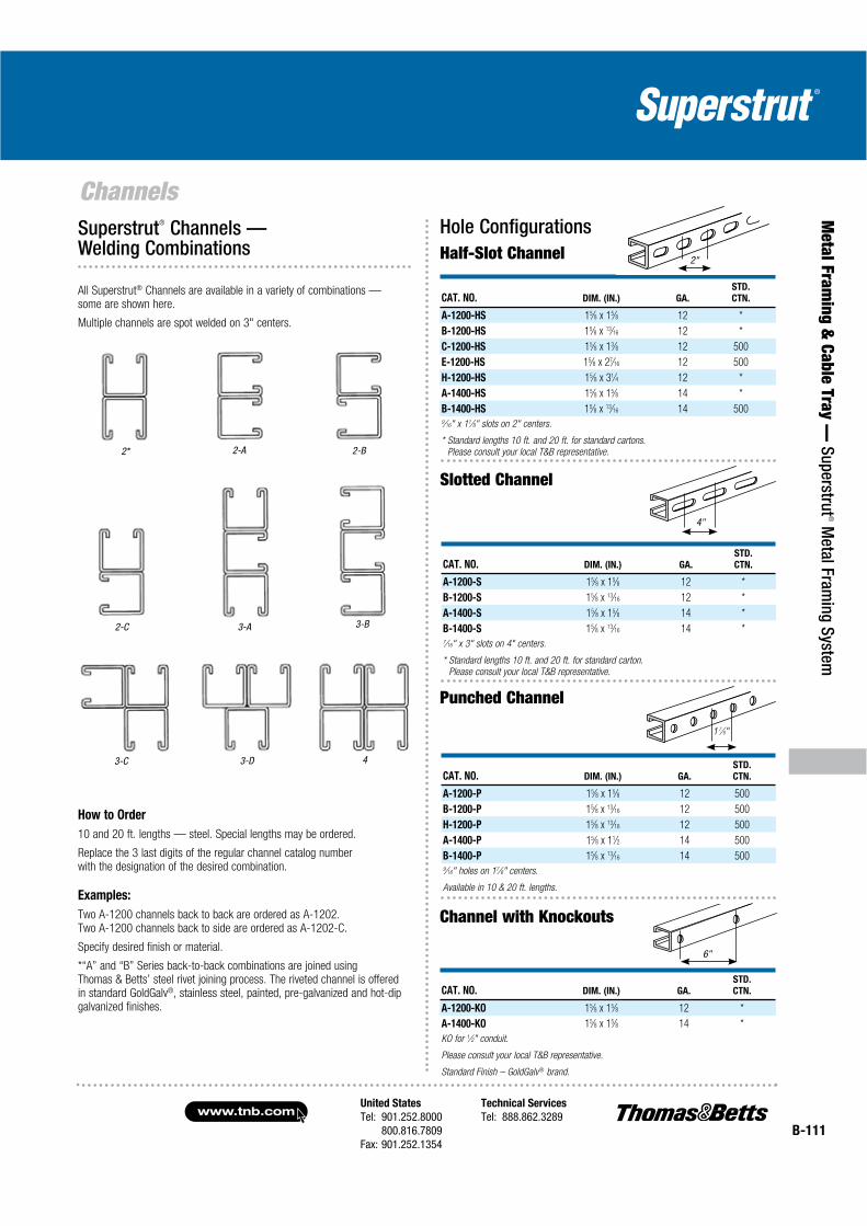
ChannelsSuperstrut® Channels — Welding Combinations
All Superstrut® Channels are available in a variety of combinations — some are shown here.
Multiple channels are spot welded on 3" centers.
2* 2-A 2-B
2-C
3-D3-C
3-A 3-B
4
How to Order
10 and 20 ft. lengths — steel. Special lengths may be ordered.
Replace the 3 last digits of the regular channel catalog number with the designation of the desired combination.
Examples:
Two A-1200 channels back to back are ordered as A-1202. Two A-1200 channels back to side are ordered as A-1202-C.
Specify desired finish or material.
*“A” and “B” Series back-to-back combinations are joined usingThomas & Betts’ steel rivet joining process. The riveted channel is offered in standard GoldGalv®, stainless steel, painted, pre-galvanized and hot-dip galvanized finishes.
CAT. NO. DIM. (IN.) GA.
STD.
CTN.
A-1200-HS 15⁄8 x 15⁄8 12 *
B-1200-HS 15⁄8 x 13⁄16 12 *
C-1200-HS 15⁄8 x 13⁄8 12 500
E-1200-HS 15⁄8 x 27⁄16 12 500
H-1200-HS 15⁄8 x 31⁄4 12 *
A-1400-HS 15⁄8 x 15⁄8 14 *
B-1400-HS 15⁄8 x 13⁄16 14 5009⁄16" x 11⁄8" slots on 2" centers.
* Standard lengths 10 ft. and 20 ft. for standard cartons.
Please consult your local T&B representative.
Hole Configurations
2"Half-Slot Channel
CAT. NO. DIM. (IN.) GA.
STD.
CTN.
A-1200-S 15⁄8 x 15⁄8 12 *
B-1200-S 15⁄8 x 13⁄16 12 *
A-1400-S 15⁄8 x 15⁄8 14 *
B-1400-S 15⁄8 x 13⁄16 14 *7⁄16" x 3" slots on 4" centers.
* Standard lengths 10 ft. and 20 ft. for standard carton.
Please consult your local T&B representative.
4"
Slotted Channel
CAT. NO. DIM. (IN.) GA.
STD.
CTN.
A-1200-P 15⁄8 x 15⁄8 12 500
B-1200-P 15⁄8 x 13⁄16 12 500
H-1200-P 15⁄8 x 13⁄16 12 500
A-1400-P 15⁄8 x 11⁄2 14 500
B-1400-P 15⁄8 x 13⁄16 14 5009⁄16" holes on 17⁄8" centers.
Available in 10 & 20 ft. lengths.
1 7⁄8"
Punched Channel
CAT. NO. DIM. (IN.) GA.
STD.
CTN.
A-1200-KO 15⁄8 x 15⁄8 12 *
A-1400-KO 15⁄8 x 15⁄8 14 *
KO for 1⁄2" conduit.
Please consult your local T&B representative.
Standard Finish – GoldGalv® brand.
6"
Channel with Knockouts
www.tnb.comUnited States
Tel: 901.252.8000800.816.7809
Fax: 901.252.1354
Technical Services
Tel: 888.862.3289B-112
Met
al F
ram
ing
& C
able
Tra
y —
Sup
erst
rut®
Met
al F
ram
ing
Syst
em
Threaded Products and Hardware
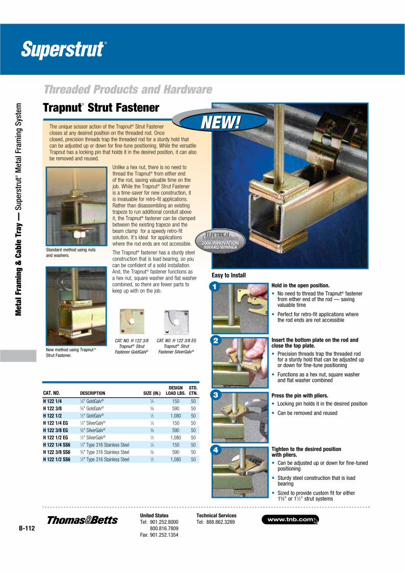
The unique scissor action of the Trapnut® Strut Fastener closes at any desired position on the threaded rod. Once closed, precision threads trap the threaded rod for a sturdy hold that can be adjusted up or down for fine-tune positioning. While the versatile Trapnut has a locking pin that holds it in the desired position, it can also be removed and reused.
Unlike a hex nut, there is no need to thread the Trapnut® from either end of the rod, saving valuable time on the job. While the Trapnut® Strut Fastener is a time-saver for new construction, it is invaluable for retro-fit applications. Rather than disassembling an existing trapeze to run additional conduit above it, the Trapnut® fastener can be clamped between the existing trapeze and the beam clamp for a speedy retro-fit solution. It’s ideal for applications where the rod ends are not accessible.
The Trapnut® fastener has a sturdy steel construction that is load bearing, so you can be confident of a solid installation. And, the Trapnut® fastener functions as a hex nut, square washer and flat washer combined, so there are fewer parts to keep up with on the job.
Trapnut® Strut Fastener
CAT. NO. DESCRIPTION SIZE (IN.)
DESIGN
LOAD LBS.
STD.
CTN.
H 122 1/4 1⁄4" GoldGalv® 1⁄4 150 50
H 122 3/8 3⁄8" GoldGalv® 3⁄8 590 50
H 122 1/2 1⁄2" GoldGalv® 1⁄2 1,080 50
H 122 1/4 EG 1⁄4" SilverGalv® 1⁄4 150 50
H 122 3/8 EG 3⁄8" SilverGalv® 3⁄8 590 50
H 122 1/2 EG 1⁄2" SilverGalv® 1⁄2 1,080 50
H 122 1/4 SS6 1⁄4" Type 316 Stainless Steel 1⁄4 150 50
H 122 3/8 SS6 3⁄8" Type 316 Stainless Steel 3⁄8 590 50
H 122 1/2 SS6 1⁄2" Type 316 Stainless Steel 1⁄2 1,080 50
Hold in the open position.
No need to thread the Trapnut® fastener from either end of the rod — saving valuable time
Perfect for retro-fit applications where the rod ends are not accessible
Press the pin with pliers.
Locking pin holds it in the desired position
Can be removed and reused
Insert the bottom plate on the rod and close the top plate.
Precision threads trap the threaded rod for a sturdy hold that can be adjusted up or down for fine-tune positioning
Functions as a hex nut, square washer and flat washer combined
Tighten to the desired position with pliers.
Can be adjusted up or down for fine-tuned positioning
Sturdy steel construction that is load bearing
Sized to provide custom fit for either 15⁄8" or 11⁄2" strut systems
1
Easy to Install
2
3
4
Standard method using nuts and washers.
New method using Trapnut ®
Strut Fastener.
CAT. NO. H 122 3/8Trapnut ® Strut
Fastener GoldGalv®
CAT. NO. H 122 3/8 EGTrapnut ® Strut
Fastener SilverGalv ®
NEW!NEW!

United States
Tel: 901.252.8000800.816.7809
Fax: 901.252.1354
Technical Services
Tel: 888.862.3289www.tnb.com
B-113
Metal Fram
ing & Cable Tray —
Superstrut® M
etal Framing System
Threaded Products and Hardware
AB-241L
CAT. NO.BOLT
SIZE (IN.)
STD.
CTN.
AB-241-1/4 1⁄4 100
AB-241-5/16 5⁄16 100
AB-241-3/8 3⁄8 100
AB-241-1/2 1⁄2 100
AB-241-5/8 5⁄8 100
AB-241-3/4 3⁄4 50
Located Square WasherSquare Washer
AB-241
Handle Retrofit Trapeze Applications with Ease!
Trap-Eze™ ConnectorThe innovative Trap-Eze™ Connector changes a time-consuming retrofit trapeze application into a streamlined process. Using a Trapnut® Strut Fastener, the new Trap-Eze™ Connector can be easily installed above or to the side of an existing assembly, eliminating the need to disassemble and reassemble the trapeze. It is designed for use with shorter strut lengths that can vary in length by as much as an inch, so the strut can be rough cut versus labor-intense precision cuts.
Easily installs above or to the side of an existing assembly, eliminating the need to disassemble and reassemble the trapeze
Connectors can be reused upon disassembly of a trapeze
Designed for either 3⁄8" and 1⁄2" threaded rod
Designed for use with the innovative Trapnut® Strut Fastener, which can take up to 43% less time than standard nuts and washers on retrofit trapeze applications
View window provides safety zone for strut length
CAT. NO. DESCRIPTION STD. CTN.
For Superstrut ® or other 15⁄8" Strut
AB221 Trap-Eze™ End Connector GoldGalv® 20
AB222 Trap-Eze™ Mid Connector GoldGalv® 10
AB221EG Trap-Eze™ End Connector SilverGalv® 20
AB222EG Trap-Eze™ Mid Connector SilverGalv® 10
For 11⁄2" Kindorf Channels
B998 Trap-Eze™ End Connector Galv-Krom® 20
B999 Trap-Eze™ Mid Connector Galv-Krom® 10
B998EG Trap-Eze™ End Connector SilverGalv® 20
B999EG Trap-Eze™ Mid Connector SilverGalv® 10
CAT. NO.BOLT
SIZE (IN.)
STD.
CTN.
AB-241L-1/4 1⁄4 100
AB-241L-5/16 5⁄16 100
AB-241L-3/8 3⁄8 100
AB-241L-1/2 1⁄2 100
AB-241L-5/8 5⁄8 100
View window provides strut length safety zone for rough cuts versus precision cuts.
Unique safety slot maintains bracket position on threaded rod
and prevents disengagement of the trapeze system.
Easily installs above existing trapeze.
Can be used to extend existing trapeze. Designed for use with
the innovative Trapnut ®
Strut Fastener.
www.tnb.comUnited States
Tel: 901.252.8000800.816.7809
Fax: 901.252.1354
Technical Services
Tel: 888.862.3289B-114
Met
al F
ram
ing
& C
able
Tra
y —
Sup
erst
rut®
Met
al F
ram
ing
Syst
em
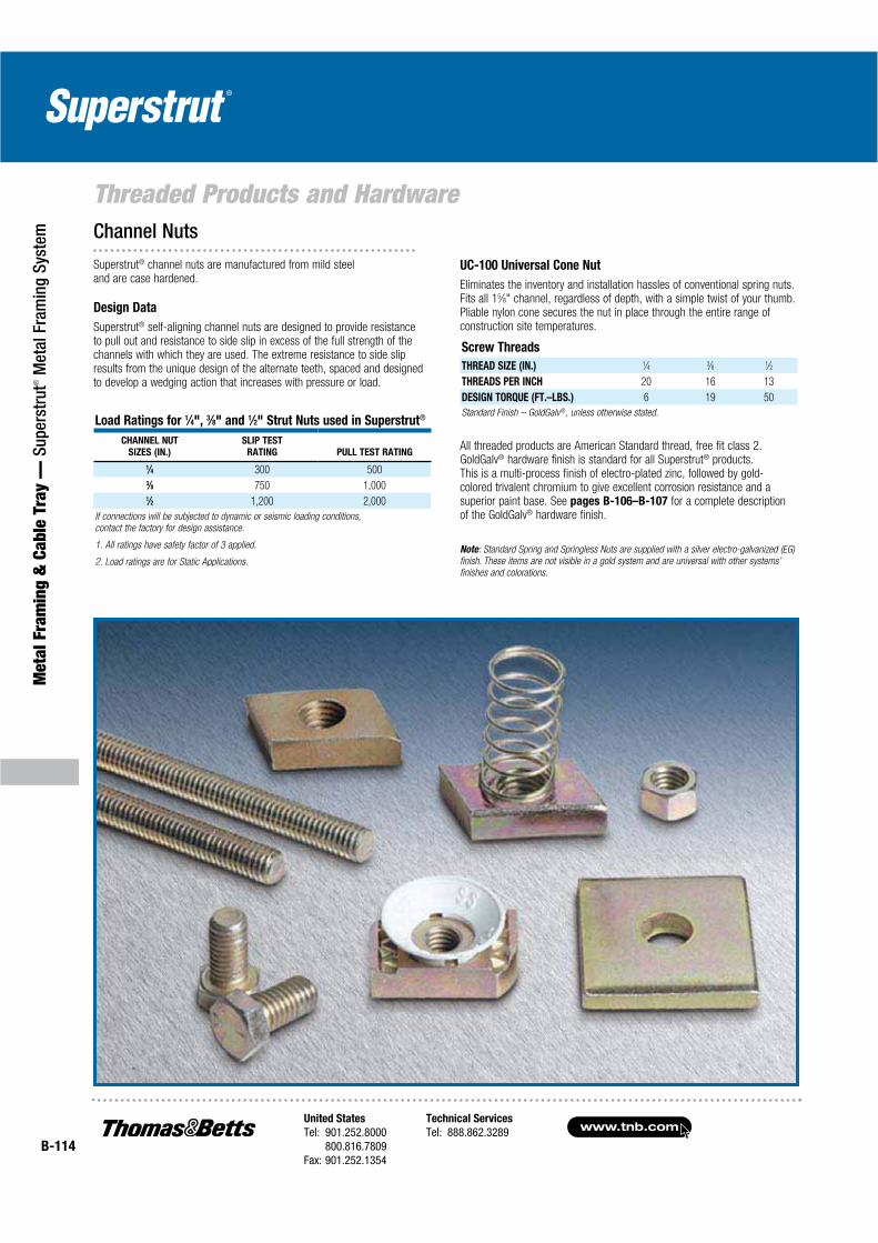
Threaded Products and HardwareChannel Nuts
UC-100 Universal Cone Nut
Eliminates the inventory and installation hassles of conventional spring nuts. Fits all 15⁄8" channel, regardless of depth, with a simple twist of your thumb. Pliable nylon cone secures the nut in place through the entire range of construction site temperatures.
Screw Threads
THREAD SIZE (IN.) 1⁄4 3⁄8 1⁄2
THREADS PER INCH 20 16 13
DESIGN TORQUE (FT.–LBS.) 6 19 50
Standard Finish – GoldGalv®, unless otherwise stated.
All threaded products are American Standard thread, free fit class 2. GoldGalv® hardware finish is standard for all Superstrut® products. This is a multi-process finish of electro-plated zinc, followed by gold-colored trivalent chromium to give excellent corrosion resistance and a superior paint base. See pages B-106–B-107 for a complete description of the GoldGalv® hardware finish.
Note: Standard Spring and Springless Nuts are supplied with a silver electro-galvanized (EG)
finish. These items are not visible in a gold system and are universal with other systems’
finishes and colorations.
Superstrut® channel nuts are manufactured from mild steel and are case hardened.
Design Data
Superstrut® self-aligning channel nuts are designed to provide resistance to pull out and resistance to side slip in excess of the full strength of the channels with which they are used. The extreme resistance to side slip results from the unique design of the alternate teeth, spaced and designed to develop a wedging action that increases with pressure or load.
Load Ratings for 1⁄4", 3⁄8" and 1⁄2" Strut Nuts used in Superstrut®
CHANNEL NUT
SIZES (IN.)
SLIP TEST
RATING PULL TEST RATING
1⁄4 300 5003⁄8 750 1,0001⁄2 1,200 2,000
If connections will be subjected to dynamic or seismic loading conditions,
contact the factory for design assistance.
1. All ratings have safety factor of 3 applied.
2. Load ratings are for Static Applications.
United States
Tel: 901.252.8000800.816.7809
Fax: 901.252.1354
Technical Services
Tel: 888.862.3289www.tnb.com
B-115
Metal Fram
ing & Cable Tray —
Superstrut® M
etal Framing System
Threaded Products and Hardware
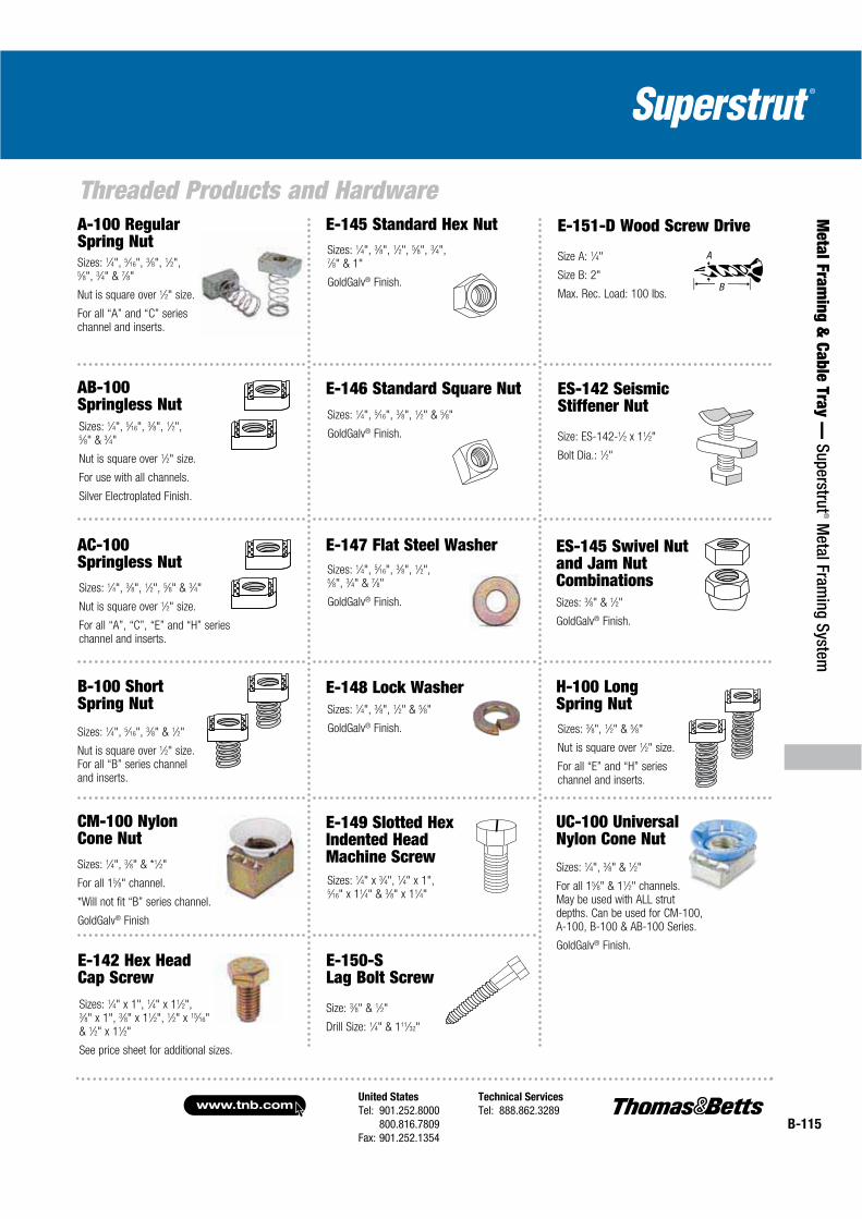
Sizes: 1⁄4", 3⁄8" & *1⁄2"
For all 15⁄8" channel.
*Will not fit “B” series channel.
GoldGalv® Finish
CM-100 Nylon Cone Nut
Sizes: 1⁄4", 5⁄16", 3⁄8" & 1⁄2"
Nut is square over 1⁄2" size. For all “B” series channel and inserts.
B-100 Short Spring Nut
Sizes: 1⁄4", 3⁄8", 1⁄2", 5⁄8" & 3⁄4"
Nut is square over 1⁄2" size.
For all “A”, “C”, “E” and “H” series channel and inserts.
AC-100Springless Nut
Sizes: 1⁄4", 5⁄16", 3⁄8", 1⁄2",5⁄8", 3⁄4" & 7⁄8"
Nut is square over 1⁄2" size.
For all “A” and “C” series channel and inserts.
A-100 Regular Spring Nut
Sizes: 1⁄4", 5⁄16", 3⁄8", 1⁄2",5⁄8" & 3⁄4"
Nut is square over 1⁄2" size.
For use with all channels.
Silver Electroplated Finish.
AB-100Springless Nut
Sizes: 1⁄4", 5⁄16", 3⁄8", 1⁄2" & 5⁄8"
GoldGalv® Finish.
E-146 Standard Square Nut
Sizes: 1⁄4", 5⁄16", 3⁄8", 1⁄2",5⁄8", 3⁄4" & 7⁄8"
GoldGalv® Finish.
E-147 Flat Steel Washer
Sizes: 1⁄4", 3⁄8", 1⁄2", 5⁄8", 3⁄4",7⁄8" & 1"
GoldGalv® Finish.
E-145 Standard Hex Nut
Sizes: 1⁄4", 3⁄8", 1⁄2" & 5⁄8"
GoldGalv® Finish.
E-148 Lock Washer
E-142 Hex Head Cap Screw Sizes: 1⁄4" x 1", 1⁄4" x 11⁄2",3⁄8" x 1", 3⁄8" x 11⁄2", 1⁄2" x 15⁄16"& 1⁄2" x 11⁄2"
See price sheet for additional sizes.
E-149 Slotted Hex Indented Head Machine ScrewSizes: 1⁄4" x 3⁄4", 1⁄4" x 1", 5⁄16" x 11⁄4" & 3⁄8" x 11⁄4"
Sizes: 3⁄8", 1⁄2" & 5⁄8"
Nut is square over 1⁄2" size.
For all “E” and “H” series channel and inserts.
H-100 Long Spring Nut
Sizes: 3⁄8" & 1⁄2"
GoldGalv® Finish.
ES-145 Swivel Nut and Jam Nut Combinations
E-150-SLag Bolt Screw
Size: 3⁄8" & 1⁄2"
Drill Size: 1⁄4" & 111⁄32"
ES-142 Seismic Stiffener Nut
Size: ES-142-1⁄2 x 11⁄2"
Bolt Dia.: 1⁄2"
E-151-D Wood Screw Drive
Size A: 1⁄4"
Size B: 2"
Max. Rec. Load: 100 lbs.
A
B
UC-100 Universal Nylon Cone Nut
Sizes: 1⁄4", 3⁄8" & 1⁄2"
For all 15⁄8" & 11⁄2" channels. May be used with ALL strut depths. Can be used for CM-100, A-100, B-100 & AB-100 Series.
GoldGalv® Finish.
www.tnb.comUnited States
Tel: 901.252.8000800.816.7809
Fax: 901.252.1354
Technical Services
Tel: 888.862.3289B-116
Met
al F
ram
ing
& C
able
Tra
y —
Sup
erst
rut®
Met
al F
ram
ing
Syst
em
Threaded Products and Hardware
CAT. NO.A
(IN.)
B
(IN.)
DESIGN
LOAD LBS.
STD.
CTN.
E120 3/8 13⁄8 3⁄8 1,000 25
E120 1/2 11⁄2 1⁄2 1,800 25
E-120 E-122
E-130 E-131
A
B
A
B
A
A
B
Standard Finish – GoldGalv ®, unless otherwise stated.
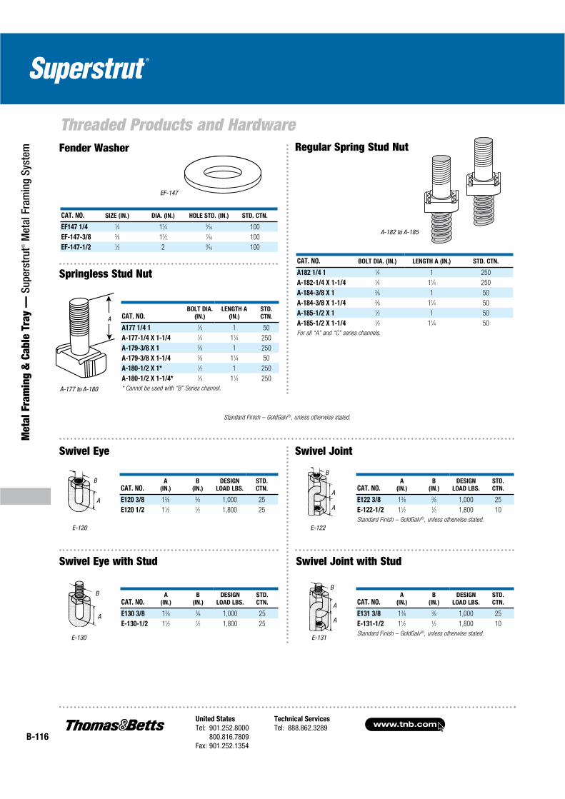
CAT. NO. SIZE (IN.) DIA. (IN.) HOLE STD. (IN.) STD. CTN.
EF147 1/4 1⁄4 11⁄4 5⁄16 100
EF-147-3/8 3⁄8 11⁄2 7⁄16 100
EF-147-1/2 1⁄2 2 9⁄16 100
EF-147
A-182 to A-185
A-177 to A-180
A
Swivel Eye
Swivel Eye with Stud
Swivel Joint
Swivel Joint with Stud
B
A
A
Fender Washer
CAT. NO.BOLT DIA.
(IN.)
LENGTH A
(IN.)
STD.
CTN.
A177 1/4 1 1⁄4 1 50
A-177-1/4 X 1-1/4 1⁄4 11⁄4 250
A-179-3/8 X 1 3⁄8 1 250
A-179-3/8 X 1-1/4 3⁄8 11⁄4 50
A-180-1/2 X 1* 1⁄2 1 250
A-180-1/2 X 1-1/4* 1⁄2 11⁄4 250
* Cannot be used with “B” Series channel.
Springless Stud NutCAT. NO. BOLT DIA. (IN.) LENGTH A (IN.) STD. CTN.
A182 1/4 1 1⁄4 1 250
A-182-1/4 X 1-1/4 1⁄4 11⁄4 250
A-184-3/8 X 1 3⁄8 1 50
A-184-3/8 X 1-1/4 3⁄8 11⁄4 50
A-185-1/2 X 1 1⁄2 1 50
A-185-1/2 X 1-1/4 1⁄2 11⁄4 50
For all “A” and “C” series channels.
Regular Spring Stud Nut
CAT. NO.A
(IN.)
B
(IN.)
DESIGN
LOAD LBS.
STD.
CTN.
E130 3/8 13⁄8 3⁄8 1,000 25
E-130-1/2 11⁄2 1⁄2 1,800 25
CAT. NO.A
(IN.)
B
(IN.)
DESIGN
LOAD LBS.
STD.
CTN.
E131 3/8 13⁄8 3⁄8 1,000 25
E-131-1/2 11⁄2 1⁄2 1,800 10
Standard Finish – GoldGalv®, unless otherwise stated.
CAT. NO.A
(IN.)
B
(IN.)
DESIGN
LOAD LBS.
STD.
CTN.
E122 3/8 13⁄8 3⁄8 1,000 25
E-122-1/2 11⁄2 1⁄2 1,800 10
Standard Finish – GoldGalv®, unless otherwise stated.

United States
Tel: 901.252.8000800.816.7809
Fax: 901.252.1354
Technical Services
Tel: 888.862.3289www.tnb.com
B-117
Metal Fram
ing & Cable Tray —
Superstrut® M
etal Framing System
Threaded Products and Hardware
CAT. NO. ROD SIZE (IN.)
STANDARD
ROD LENGTHS STD. CTN.
E-151-3/8 3⁄8 4, 6, 8, 10, 12 100
E-151-1/2 1⁄2 4, 6, 8, 10 100
CAT. NO.ROD SIZE
(IN.)
A
(IN.)
STD.
CTN.
H119-1/4 1⁄4 7⁄8 50
H119-5/16 5⁄167⁄8 50
H119-3/8 3⁄8 11⁄8 50
H119-1/2 1⁄2 11⁄4 50
H119-5/8 5⁄8 21⁄8 50
H119-3/4 3⁄4 21⁄4 50
H119-7/8 7⁄8 21⁄2 50
H119-1 1 21⁄4 50
Standard Finish – GoldGalv ®,
unless otherwise stated.
A
A
CAT. NO. CONDUIT SIZE (IN.) MAX. FLANGE THICKNESS (IN.) DIM. A (IN.) STD. CTN.
U-571 1⁄2 1 13⁄4 25
U-571 3⁄4 3⁄4 13⁄4 25
U-571 1 1⁄2 13⁄4 25
U-572 3⁄4 11⁄2 21⁄2 25
U-572 1 11⁄4 21⁄2 25
U-572 11⁄4 1 21⁄2 25
U-572 11⁄2 5⁄8 21⁄2 25
Standard Finish – GoldGalv® brand.
For attaching 1⁄2" thru 11⁄2" conduit to beam, channel, angle or column.
Secures conduit to the support parallel or at right angles to it.
5⁄16" set screw, 12 ga. material.U-571, U-572
A
E-151 — Coach Screw Rod
Standard Rod Coupling
Reducing Rod Coupling
CAT. NO.ROD SIZE
(IN.)
A
(IN.)
STD.
CTN.
H119-1/4X3/8 1⁄4–3⁄8 11⁄2 50
H119-3/8X1/2 3⁄8–1⁄2 11⁄4 50
H119-1/2X5/8 1⁄2–5⁄8 11⁄4 50
H119-5/8X3/4 5⁄8–3⁄4 11⁄2 50
H119-3/4X7/8 3⁄4–7⁄8 13⁄4 50
Standard Finish – GoldGalv ®,
unless otherwise stated.
U-571, U-572 Conduit Clamp
CAT. NO. SIZE
WT./LBS.
PER 100 PCS.
H104 1/4X6 73
H104 1/4X10 1⁄4"–20 124
H104 1/4X12 148
H104 3/8X6 172
H104 3/8X10 3⁄8"–16 293
H104 3/8X12 348
H104 1/2X6 313
H104 1/2X10 1⁄2"–13 530
H104 1/2X12 648
H104 5/8X6 510
H104 5/8X10 5⁄8"–11 850
H104 5/8X12 1,020
Suffix indicates rod size and length.
H104 Hanger Rod,Continuous Thread —GoldGalv®
CAT. NO. SIZE
WT./LBS.
PER 100 PCS.
H104 1/4X6-EG 73
H104 1/4X10-EG 1⁄4"–20 124
H104 1/4X12-EG 148
H104 3/8X6-EG 172
H104 3/8X10-EG 3⁄8"–16 293
H104 3/8X12-EG 348
H104 1/2X6-EG 313
H104 1/2X10-EG 1⁄2"–13 530
H104 1/2X12-EG 648
H104 5/8X6-EG 510
H104 5/8X10-EG 5⁄8"–11 850
H104 5/8X12-EG 1,020
Suffix indicates rod size and length.
H104-EG Hanger Rod, Continuous Thread — SilverGalv®
H-104 Series Rod
www.tnb.comUnited States
Tel: 901.252.8000800.816.7809
Fax: 901.252.1354
Technical Services
Tel: 888.862.3289B-118
Met
al F
ram
ing
& C
able
Tra
y —
Sup
erst
rut®
Met
al F
ram
ing
Syst
em
Fittings and Brackets
13⁄16
7⁄89⁄16
5⁄81⁄4
...........................Standard Dimensions........................
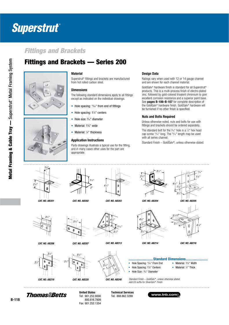
Fittings and Brackets — Series 200
Material
Superstrut® fittings and brackets are manufactured from hot rolled carbon steel.
Dimensions
The following standard dimensions apply to all fittings except as indicated on the individual drawings.
13⁄16
7⁄8
9⁄16
5⁄8
1⁄4
Application Instructions
Parts drawings illustrate a typical use for the fitting, and in many cases other uses for the part are appropriate.
Design Data
Ratings vary when used with 12 or 14 gauge channel and are shown for each channel material.
GoldGalv® hardware finish is standard for all Superstrut®
products. This is a multi-process finish of electro-plated zinc, followed by gold-colored trivalent chromium to give excellent corrosion resistance and a superior paint base. See pages B-106–B-107 for complete description of the GoldGalv® hardware finish. GoldGalv® hardware will be furnished if no other finish is specified.
Nuts and Bolts Required
Unless otherwise noted, nuts and bolts for use with fittings and brackets should be ordered separately.
The standard bolt for the 9⁄16" hole is a 1⁄2" hex head cap screw 15⁄16" long. The 15⁄16" length may be used with all series channel.
Standard Finish – GoldGalv®, unless otherwise stated.
17⁄16"
31⁄2"
41⁄8"
CAT. NO. AB214
41⁄8"
31⁄2"
31⁄2"
CAT. NO. AB216
Standard Finish – GoldGalv ®, unless otherwise stated.
Add EG suffix for SilverGalv ® Finish
41⁄8"
17⁄16"
31⁄2"
31⁄2"
21⁄4"
CAT. NO. AB204
CAT. NO. AB213
CAT. NO. AB205
13⁄16"
17⁄8"
41⁄8"17⁄16"
31⁄2"
CAT. NO. AB201
2"
17⁄8"
CAT. NO. AB202
CAT. NO. AB206 CAT. NO. AB207
31⁄2"
53⁄8"
3 1⁄2"
3 1⁄2"
CAT. NO. AB219
5 3⁄8"
3 1⁄2"
CAT. NO. AB220 CAT. NO. AB240
7"
3 5⁄8"
CAT. NO. AB203
41⁄8"
15⁄8"
21⁄4"

United States
Tel: 901.252.8000800.816.7809
Fax: 901.252.1354
Technical Services
Tel: 888.862.3289www.tnb.com
B-119
Metal Fram
ing & Cable Tray —
Superstrut® M
etal Framing System
Fittings and Brackets
CAT. NO. A (IN.) STD. CTN.
AB252 1 3 7⁄8 10
AB252 2 5 7⁄8 10
AB252 3 7 7⁄8 10
AB252 4 9 7⁄8 10
CAT. NO. AB274
A
17⁄8"
CAT. NO. AB252CAT. NO. AB-242
For use with either 3⁄8"or 1⁄2" hanger rod
3 1⁄2"
41⁄8"
17⁄16"
3 1⁄2"
CAT. NO. AB254 R
17⁄16"
41⁄8"
CAT. NO. AB254 L
CAT. NO. AB284 R
3 1⁄2"
41⁄8"
5 3⁄8"
CAT. NO. AB284 L
5 3⁄8"
41⁄8"
3 1⁄2"
CAT. NO. AB299
2"
2"
CAT. NO. X201
2 1⁄2"
2 1⁄2"4 7⁄8"
17⁄8"
CAT. NO. X299
11⁄2"
15⁄16"
15⁄8"2 5⁄8"
CAT. NO. X289
4 1⁄8"
31⁄2"13⁄8"
11⁄2”
CAT. NO. N205
3 7⁄8"
1"
11⁄16"33⁄4"
CAT. NO. X204
Slot size is 9⁄16" x 11⁄2"
6 3⁄8"
17⁄8"
4"
3 3⁄4"
3 1⁄2"
5 3⁄8"
CAT. NO. N-219
31⁄2"
15⁄8"
21⁄4"
3 1⁄2"
17⁄8"
2"
CAT. NO. AB260 R
17⁄8"
2"3 1⁄2"
CAT. NO. AB260 L
CAT. NO. AB253
5 3⁄8"
5 3⁄8"
3 1⁄2"
3 1⁄2"
CAT. NO. AB257
5 3⁄8"
31⁄2"
CAT. NO. AB261
5 3⁄8"
5 3⁄8"
CAT. NO. AB263
5 3⁄8"
5 3⁄8"
CAT. NO. AB265
5 3⁄8"
31⁄2"
7 1⁄4"
9 1⁄8"
CAT. NO. X208
5 3⁄8"
13⁄16
7⁄89⁄16
5⁄81⁄4
...........................Standard Dimensions............................
Standard Finish – GoldGalv ®, unless otherwise stated.
Add EG suffix for SilverGalv ® Finish
CAT. NO. AB255
CAT. NO. X207

www.tnb.comUnited States
Tel: 901.252.8000800.816.7809
Fax: 901.252.1354
Technical Services
Tel: 888.862.3289B-120
Met
al F
ram
ing
& C
able
Tra
y —
Sup
erst
rut®
Met
al F
ram
ing
Syst
em
Fittings and Brackets
Hole Spacing: 13⁄16" From End
Hole Spacing: 17⁄8" Centers
Hole Size: 1" Diameter
Material: 15⁄8" Width
Material: 1⁄4" Thick
Standard Finish – GoldGalv ®, unless otherwise stated.
Add EG suffix for SilverGalv ® Finish
Z Shape Fittings
CAT. NO. B209
For attaching “B” series channel.CAT. NO. C209
For attaching “C” series channel.
13⁄8"
2 1⁄8"
11⁄16"
CAT. NO. A209
For attaching “A” series channel.
11⁄16"
2 1⁄8"
15⁄8"
2 1⁄8"
11⁄16"
13⁄16"
CAT. NO. EZ209
For attaching “E” series channel.
17⁄8"
2 7⁄16"
CAT. NO. CZ209
For attaching “A” back to back.
17⁄8"
31⁄4"............. Standard Dimensions .............
CAT. NO. A217 CAT. NO. A218 CAT. NO. AW204
121⁄32"15⁄8"
3 3⁄4"3 7⁄8"
121⁄32"15⁄8"
3 7⁄8"
2"17⁄8"
5 7⁄8"
13⁄4"17⁄8"
CAT. NO. AW205 L
CAT. NO. AW205-R CAT. NO. AW214
17⁄8"
3 7⁄8"
1 3⁄4"
1 7⁄8"
CAT. NO. AW219 CAT. NO. AW220
3 7⁄8"
15⁄8" 121⁄32"
9 5⁄32"
15⁄8" 121⁄32"
2"
17⁄8"
5 13⁄32"
Wing Shape Fittings
Hole Spacing: 13⁄16" From End
Hole Spacing: 17⁄8" Centers
Hole Size: 1" Diameter
Material: 15⁄8" Width
Material: 1⁄4" Thick
Standard Finish – GoldGalv ®, unless otherwise stated.
Add EG suffix for SilverGalv ® Finish
............. Standard Dimensions .............
CAT. NO. AW224
15⁄8" 121⁄32"
3 7⁄8"
CAT. NO. AW226 CAT. NO. AW228
121⁄32"15⁄8"
3 7⁄8"
3 3⁄4"
9 5⁄32"
1 21⁄32"1 5⁄8"
2"
5 13⁄32"17⁄8"5 7⁄16"

United States
Tel: 901.252.8000800.816.7809
Fax: 901.252.1354
Technical Services
Tel: 888.862.3289www.tnb.com
B-121
Metal Fram
ing & Cable Tray —
Superstrut® M
etal Framing System
Fittings and BracketsU Shape Fittings
CAT. NO. A208
Does not include strut nut or bolts. For “A” series channel.
CAT. NO. A210
For attaching “A” series channelCAT. NO. A211
For attaching “A” series channel.
7 1⁄4"
15⁄8"
5 3⁄8"5 3⁄8"
3 1⁄4"
CAT. NO. A212
3 9⁄32"1 5⁄8"
7"
CAT. NO. C210
For attaching “C” series channel.CAT. NO. E210
For attaching “E” series channel.
2 7⁄16"
5 3⁄8"
121⁄32"
5 3⁄8"
CAT. NO. AB245 CAT. NO. AB-288
3 9⁄32"
17⁄8"
121⁄32"
11⁄16"
1"
121⁄32"
1⁄4"
10 ga.
11⁄2"2 1⁄2"
3⁄4"-16UNF
Thread
CAT. NO. A-213
111⁄32"
3⁄32"13⁄8"
4 1⁄2"7⁄8"
CAT. NO. B210
5 3⁄8"
1 21⁄32"
3⁄16"
13⁄8"
4 7⁄8"
5 3⁄8"
1 21⁄32"
121⁄32"
1 5⁄8"
Hole Spacing: 13⁄16" From End
Hole Spacing: 17⁄8" Centers
Hole Size: 1" Diameter
Material: 15⁄8" Width
Material: 1⁄4" Thick
Standard Finish – GoldGalv ®,
unless otherwise stated.
Add EG suffix for SilverGalv ® Finish
Standard Dimensions
CAT. NO. AB227
11⁄16"
3"45˚
2 5⁄16"
15⁄8"
B
15⁄8"
A
CAT. NO.A
(IN.)
B
(IN.)
STD.
CTN.
AB239 1 713⁄16 81⁄2 15
AB-239-2 133⁄4 17 10
AB-239-3 193⁄4 251⁄2 10
Standard Finish – GoldGalv ®, unless otherwise stated.
Add EG suffix for SilverGalv ® FinishCAT. NO. AB-239
21⁄2"
45˚31⁄2"
CAT. NO. AB225
Angular Fittings
CAT. NO. AN211

www.tnb.comUnited States
Tel: 901.252.8000800.816.7809
Fax: 901.252.1354
Technical Services
Tel: 888.862.3289B-122
Met
al F
ram
ing
& C
able
Tra
y —
Sup
erst
rut®
Met
al F
ram
ing
Syst
em
Fittings and BracketsPost Bases
CAT. NO. AP-232
CAT. NO. AP-232SQ
31⁄2"
111⁄16"15⁄8"
4 Holes3⁄4" Dia.
111⁄16"
6"
41⁄4" 41⁄4"
6"
31⁄2"
4 Holes3⁄4" Dia.
6"6"
41⁄4"
3 1⁄2"
4 Holes3⁄4" Dia.
3 5⁄16"
41⁄4"
CAT. NO. AP-232FL CAT. NO. AP-235FL
CAT. NO. AP-231
CAT. NO. AP-231SQ CAT. NO. AP-234SQ
CAT. NO. AP-234FL
CAT. NO. AW-239
CAT. NO. AP-235SQCAT. NO. AP-206
5"
31⁄2"4 Holes7⁄16" Dia.
5⁄8"
Standard Finish – GoldGalv ®, unless otherwise stated.
Add EG suffix for SilverGalv ® Finish
2 Holes3⁄4" Dia.
8" 6 1⁄2"
3 1⁄8"
15⁄8"
15⁄8"
3 3⁄8"
41⁄2"
15⁄8"
111⁄16"
15⁄8"
6"41⁄2"
4 Holes3⁄4" Dia.
6"
4 1⁄2"
15⁄8"
111⁄16"
15⁄8"
6"
4 1⁄2"
4 Holes3⁄4" Dia.
6"
2 Holes3⁄4" Dia.
3"
61⁄2"
3 1⁄2"
111⁄16"15⁄8"
8"
CAT. NO. AP-231FL
3"
61⁄2"
15⁄8"
111⁄16"15⁄8"
8"
2 Holes3⁄4" Dia.
8"6 1⁄2"
3 1⁄8"
3 1⁄2"
15⁄8"
3 3⁄8"2 Holes3⁄4" Dia.
CAT. NO. AP-234
4 Holes3⁄4" Dia.
41⁄2"6"
41⁄2"
15⁄8"
15⁄8"
3 3⁄8"
6"
15⁄8"
15⁄8"
115⁄16"
3 3⁄8"
31⁄8"
3⁄4" Dia.
15⁄8"
15⁄8"
3 3⁄8"4 Holes3⁄4" Dia.
41⁄2"6"
4 1⁄2" 6"
CAT. NO. AP-235
6”
3 1⁄4"
6" 4 Holes3⁄4" Dia.
3 1⁄2"
6"
15⁄8"
United States
Tel: 901.252.8000800.816.7809
Fax: 901.252.1354
Technical Services
Tel: 888.862.3289www.tnb.com
B-123
Metal Fram
ing & Cable Tray —
Superstrut® M
etal Framing System
Fittings and Brackets
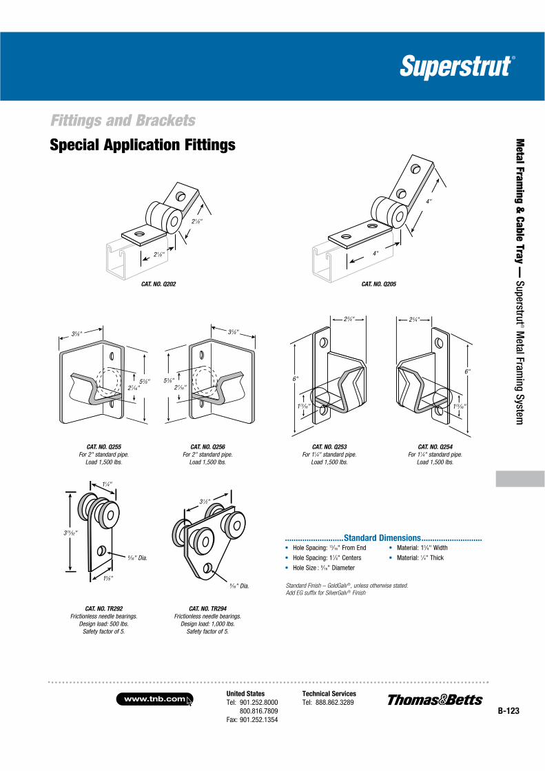
CAT. NO. Q254
For 11⁄4" standard pipe. Load 1,500 lbs.
CAT. NO. TR294
Frictionless needle bearings.Design load: 1,000 lbs.
Safety factor of 5.
CAT. NO. TR292
Frictionless needle bearings.Design load: 500 lbs.
Safety factor of 5.
CAT. NO. Q253
For 11⁄4" standard pipe.Load 1,500 lbs.
2 3⁄4"
6"
113⁄16"
3 5⁄8"
5 3⁄8"2 7⁄16"
35⁄8"
27⁄16"53⁄8"
CAT. NO. Q202
2 1⁄8"
2 1⁄8"
2 3⁄4"
6"
113⁄16"
CAT. NO. Q256
For 2" standard pipe.Load 1,500 lbs.
CAT. NO. Q255
For 2" standard pipe.Load 1,500 lbs.
Special Application Fittings
15⁄8"
9⁄16" Dia.
315⁄32"
11⁄4"
13⁄16
7⁄8
9⁄16
5⁄8
1⁄4
...........................Standard Dimensions............................
Standard Finish – GoldGalv ®, unless otherwise stated.
Add EG suffix for SilverGalv ® Finish
9⁄16" Dia.
3 1⁄2"
CAT. NO. Q205
4"
4"
www.tnb.comUnited States
Tel: 901.252.8000800.816.7809
Fax: 901.252.1354
Technical Services
Tel: 888.862.3289B-124
Met
al F
ram
ing
& C
able
Tra
y —
Sup
erst
rut®
Met
al F
ram
ing
Syst
em
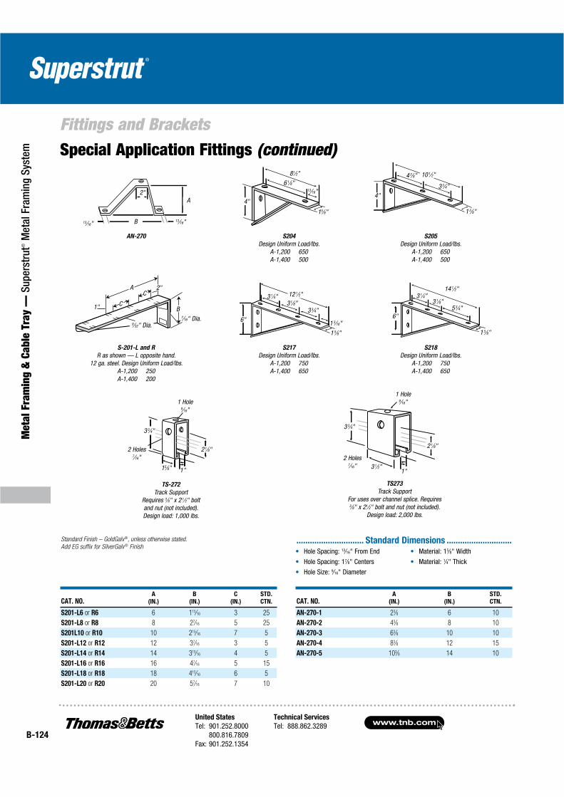
Fittings and Brackets
S-201-L and R
R as shown — L opposite hand. 12 ga. steel. Design Uniform Load/lbs.
A-1,200 250 A-1,400 200
TS-272
Track SupportRequires 3⁄8" x 2 1⁄2" boltand nut (not included).Design load: 1,000 lbs.
TS273
Track SupportFor uses over channel splice. Requires 3⁄8" x 21⁄2" bolt and nut (not included).
Design load: 2,000 lbs.
2 1⁄8"
1"3 1⁄2"
3 3⁄4"3 3⁄4"
15⁄8" 1"
2 1⁄8"
1 Hole9⁄16"
1 Hole9⁄16"
2 Holes7⁄16" 2 Holes
7⁄16"
6 1⁄8"81⁄2"
15⁄8"
13⁄16"
4"
S205
Design Uniform Load/lbs.A-1,200 650 A-1,400 500
1 5⁄8"
3 3⁄4"
4 3⁄8"
4"
10 1⁄2"
S204
Design Uniform Load/lbs.A-1,200 650 A-1,400 500
S218
Design Uniform Load/lbs.A-1,200 750 A-1,400 650
S217
Design Uniform Load/lbs.A-1,200 750 A-1,400 650
1 5⁄8"
6"
3 1⁄4"3 1⁄8"
14 1⁄2"
5 3⁄4"
1 3⁄16"6"
3 1⁄4"31⁄8"
3 3⁄4"
1 5⁄8"
12 1⁄2"
.............................. Standard Dimensions .............................Hole Spacing: 13⁄16" From End
Hole Spacing: 17⁄8" Centers
Hole Size: 9⁄16" Diameter
Material: 15⁄8" Width
Material: 1⁄4" Thick
CAT. NO.A
(IN.)
B
(IN.)
STD.
CTN.
AN-270-1 23⁄8 6 10
AN-270-2 43⁄8 8 10
AN-270-3 63⁄8 10 10
AN-270-4 83⁄8 12 15
AN-270-5 103⁄8 14 10
CAT. NO.A
(IN.)
B
(IN.)
C
(IN.)
STD.
CTN.
S201-L6 or R6 6 115⁄16 3 25
S201-L8 or R8 8 27⁄16 5 25
S201L10 or R10 10 215⁄16 7 5
S201-L12 or R12 12 37⁄16 3 5
S201-L14 or R14 14 315⁄16 4 5
S201-L16 or R16 16 47⁄16 5 15
S201-L18 or R18 18 415⁄16 6 5
S201-L20 or R20 20 57⁄16 7 10
Standard Finish – GoldGalv®, unless otherwise stated.
Add EG suffix for SilverGalv ® Finish
AN-270
13⁄16" 13⁄16"
A2"
B
Special Application Fittings (continued)
1"
9⁄32" Dia.7⁄16" Dia.
2"AC
BC
United States
Tel: 901.252.8000800.816.7809
Fax: 901.252.1354
Technical Services
Tel: 888.862.3289www.tnb.com
B-125
Metal Fram
ing & Cable Tray —
Superstrut® M
etal Framing System
Fittings and Brackets
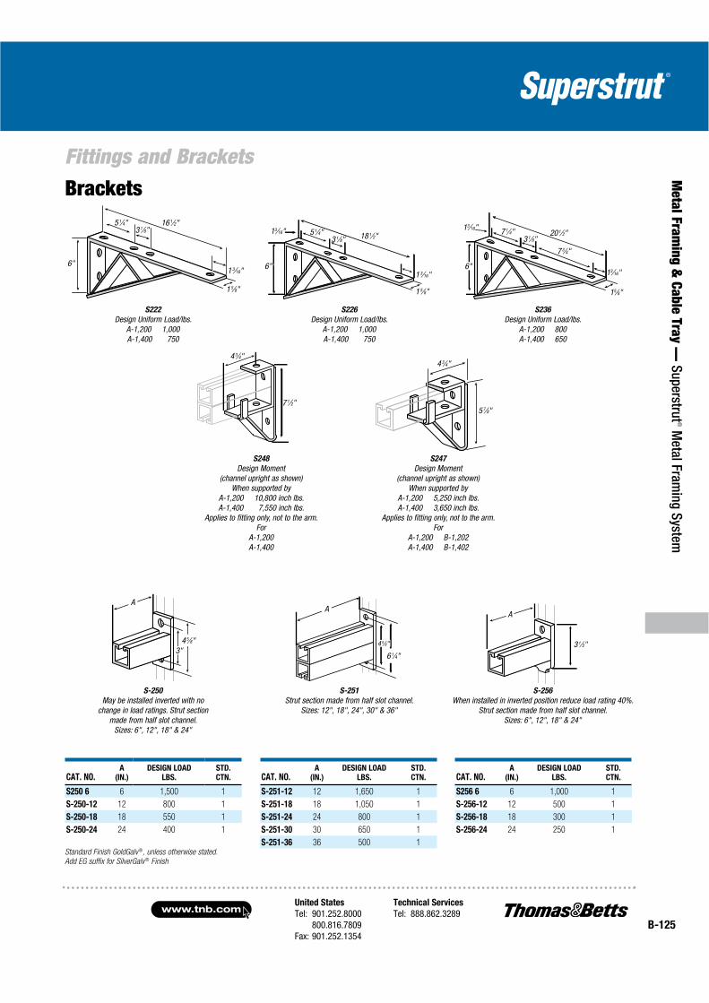
6"
16 1⁄2"5 1⁄4"3 1⁄8"
1 3⁄16"
1 5⁄8"
S236
Design Uniform Load/lbs.A-1,200 800 A-1,400 650
15⁄8"
13⁄16"
20 1⁄2"3 1⁄8"
7 1⁄4"13⁄16"
7 3⁄4"
S248
Design Moment(channel upright as shown)
When supported byA-1,200 10,800 inch lbs. A-1,400 7,550 inch lbs.
Applies to fitting only, not to the arm.For
A-1,200A-1,400
S-250
May be installed inverted with no change in load ratings. Strut section
made from half slot channel.Sizes: 6", 12", 18" & 24"
CAT. NO.A
(IN.)
DESIGN LOAD
LBS.
STD.
CTN.
S250 6 6 1,500 1
S-250-12 12 800 1
S-250-18 18 550 1
S-250-24 24 400 1
4 3⁄4"
7 1⁄2"
4 5⁄8"3"
A
4 3⁄4"
5 7⁄8"
S-256
When installed in inverted position reduce load rating 40%. Strut section made from half slot channel.
Sizes: 6", 12", 18" & 24"
S-251
Strut section made from half slot channel. Sizes: 12", 18", 24", 30" & 36"
3 1⁄2"
A
Standard Finish GoldGalv ®, unless otherwise stated.
Add EG suffix for SilverGalv ® Finish
S222
Design Uniform Load/lbs.A-1,200 1,000 A-1,400 750
4 5⁄8"
A
6 1⁄4"
Brackets
1 5⁄8"
18 1⁄2"3 1⁄8"5 1⁄4"13⁄16"
6" 1 3⁄16"
S226
Design Uniform Load/lbs.A-1,200 1,000 A-1,400 750
S247
Design Moment(channel upright as shown)
When supported byA-1,200 5,250 inch lbs. A-1,400 3,650 inch lbs.
Applies to fitting only, not to the arm.For
A-1,200 B-1,202A-1,400 B-1,402
CAT. NO.A
(IN.)
DESIGN LOAD
LBS.
STD.
CTN.
S-251-12 12 1,650 1
S-251-18 18 1,050 1
S-251-24 24 800 1
S-251-30 30 650 1
S-251-36 36 500 1
CAT. NO.A
(IN.)
DESIGN LOAD
LBS.
STD.
CTN.
S256 6 6 1,000 1
S-256-12 12 500 1
S-256-18 18 300 1
S-256-24 24 250 1
6"

www.tnb.comUnited States
Tel: 901.252.8000800.816.7809
Fax: 901.252.1354
Technical Services
Tel: 888.862.3289B-126
Met
al F
ram
ing
& C
able
Tra
y —
Sup
erst
rut®
Met
al F
ram
ing
Syst
em
Concrete Inserts
C-302
C-804
B-302
B804
4"
4"
C-302
15⁄8"13⁄8"
2 1⁄2"
13⁄16"
11⁄8"
B-302
15⁄8"
115⁄16"11⁄8"
13⁄16"
13⁄16"
Standard lengths 10 ft. and 20 ft. length tolerance 3⁄16". Assemblies available in any length from 12" to 20 ft. Consult factory.
Insert with end caps and foam filler strip installed.
Material:
B-302 and C-302 Insert Channel — 12 ga. steel. B-804 and C-804 End Caps — 12 ga. steel.Superstrut® continuous insert channel is cold formed from 12 gauge hot-rolled strip steel in two basic sizes as follows:
CAT. NO. B-302
15⁄8" x 13⁄16" dim. 7⁄8" slot
CAT. NO. C-302
15⁄8" x 13⁄8" dim. 7⁄8" slot
Finishes
Product is available in GoldGalv® pre-galvanized (PG), hot-dipped galvanized (HDG) and stainless steel (SS). Contact your T&B Sales team for delivery and pricing.
Standard lengths are 10 ft. and 20 ft. Product is supplied with foam filler and end caps to prevent seepage of concrete into channel.
Application
For casting into concrete walls, floors or ceilings to provide attachment anywhere along the continuous slot.
Design Data
Load ratings as shown have a safety factor of 3 in 3,000 lb. hard rock concrete. Where “good” concrete does not exist, the load ratings shall not apply.
GoldGalv® hardware finish is standard for all Superstrut® products. This is a multi-process finish of electro-plated zinc, followed by gold-colored trivalent chromium to give excellent corrosion resistance and a superior paint base. See pages B-106–B-107 for a complete description of the GoldGalv®
hardware finish. GoldGalv® hardware will be furnished if no other finishis specified.
Standard Finish – GoldGalv ®, unless otherwise stated.
Design Load lbs.
2,000 lbs. per foot in 3,000 lbs. hard rock concrete with a safety factor of 2.
CAT. NO. DESCRIPTION
B-302* Insert channel 12 ga. steel — 13⁄16" depth
C-302* Insert channel 12 ga. steel — 13⁄8" depth
B804 End cap in B Series Concrete Insert
C-804 End cap in C Series Concrete Insert
*Add suffix -10 for 10' lengths and -20 for 20' lengths
NOTE: B-302 and C-302 are furnished with:
A. Concrete safe tape applied to interior of channel to cover holes.
B. Styrene insert between tape and 7⁄8" continuous opening.
C. Two end caps on either side of strut to prevent concrete seepage.
Concrete Inserts (Series 300/400)
United States
Tel: 901.252.8000800.816.7809
Fax: 901.252.1354
Technical Services
Tel: 888.862.3289www.tnb.com
B-127
Metal Fram
ing & Cable Tray —
Superstrut® M
etal Framing System
Concrete Inserts
CAT. NO.FOR
CHANNEL
X
(IN.) MATERIAL
STD.
CTN.
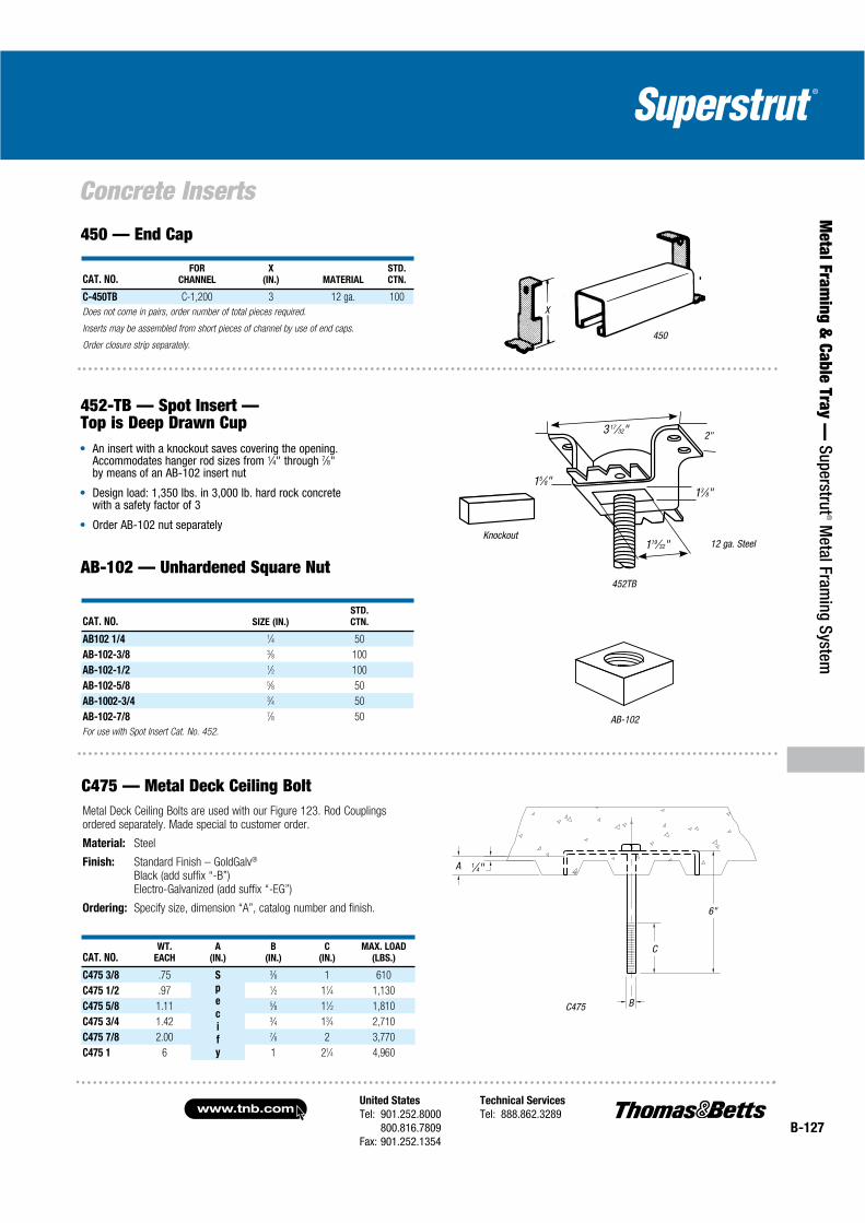
C-450TB C-1,200 3 12 ga. 100
Does not come in pairs, order number of total pieces required.
Inserts may be assembled from short pieces of channel by use of end caps.
Order closure strip separately.
450 — End Cap
452-TB — Spot Insert — Top is Deep Drawn Cup
An insert with a knockout saves covering the opening.Accommodates hanger rod sizes from 1⁄4" through 7⁄8"by means of an AB-102 insert nut
Design load: 1,350 lbs. in 3,000 lb. hard rock concrete with a safety factor of 3
Order AB-102 nut separately
CAT. NO. SIZE (IN.)
STD.
CTN.
AB102 1/4 1⁄4 50
AB-102-3/8 3⁄8 100
AB-102-1/2 1⁄2 100
AB-102-5/8 5⁄8 50
AB-1002-3/4 3⁄4 50
AB-102-7/8 7⁄8 50
For use with Spot Insert Cat. No. 452.
AB-102 — Unhardened Square Nut
C475 — Metal Deck Ceiling BoltMetal Deck Ceiling Bolts are used with our Figure 123. Rod Couplings ordered separately. Made special to customer order.
Material: Steel
Finish: Standard Finish – GoldGalv®
Black (add suffix “-B”)Electro-Galvanized (add suffix “-EG”)
Ordering: Specify size, dimension “A”, catalog number and finish.
CAT. NO.WT.
EACH
A
(IN.)
B
(IN.)
C
(IN.)
MAX. LOAD
(LBS.)
C475 3/8 .75 S
p
e
c
i
f
y
3⁄8 1 610
C475 1/2 .97 1⁄2 11⁄4 1,130
C475 5/8 1.11 5⁄8 11⁄2 1,810
C475 3/4 1.42 3⁄4 13⁄4 2,710
C475 7/8 2.00 7⁄8 2 3,770
C475 1 6 1 21⁄4 4,960
450
x
452TB
AB-102
Knockout
13⁄8"
2"3 17⁄32"
15⁄8"
119⁄32" 12 ga. Steel
C475
6"
B
A 1⁄4"
C
X
www.tnb.comUnited States
Tel: 901.252.8000800.816.7809
Fax: 901.252.1354
Technical Services
Tel: 888.862.3289B-128
Met
al F
ram
ing
& C
able
Tra
y —
Sup
erst
rut®
Met
al F
ram
ing
Syst
em
Beam Clamps
Materials
Most products are manufactured from hot-rolled carbon steel bars or hot-rolled strip steel. Pipe rollers are cast iron. Products which are copper placed carry the letter “T” in the prefix.
Design Loads
Where design loads are indicated, they provide for a safety factor of 3 in conformance with the “AMERICAN STANDARD CODE FOR PRESSURE PIPING.”
GoldGalv® hardware finish is standard for all Superstrut® products. This is a multi-processfinish of electro-plated zinc, followed by gold-colored trivalent chromium to give excellentcorrosion resistance and a superior paint base. See pages B-106–B-107 for a completedescription of the GoldGalv® hardware finish. GoldGalv® hardware will be furnished ifno other finish is specified.
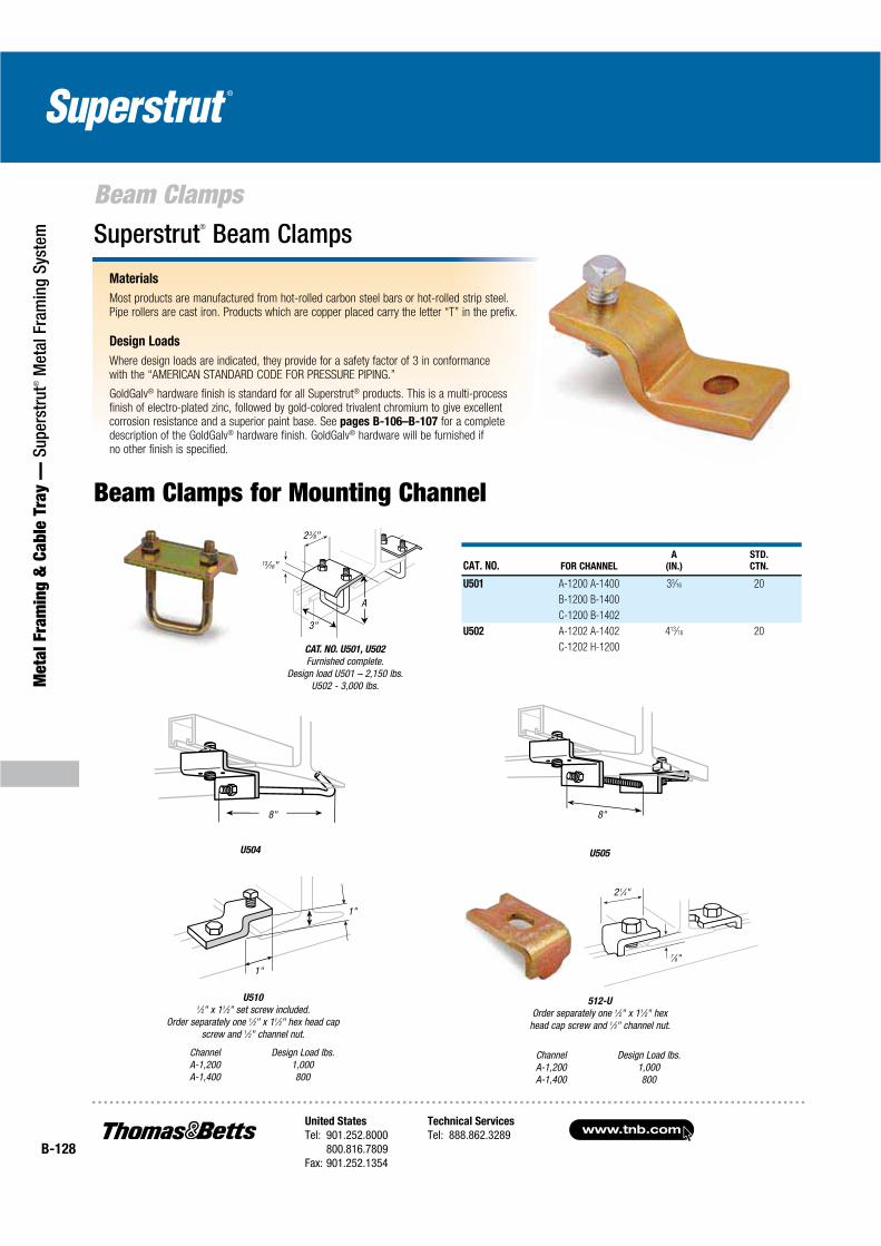
Superstrut® Beam Clamps
Beam Clamps for Mounting Channel
CAT. NO. FOR CHANNEL
A
(IN.)
STD.
CTN.
U501 A-1200 A-1400 33⁄16 20
B-1200 B-1400
C-1200 B-1402
U502 A-1202 A-1402 413⁄16 20
C-1202 H-1200
8"
U505
CAT. NO. U501, U502
Furnished complete.Design load U501 – 2,150 lbs.
U502 - 3,000 lbs.
U504
8"
3"
23⁄8"
A
13⁄16"
1"
1"
U5101⁄2" x 11⁄2" set screw included.
Order separately one 1⁄2" x 11⁄2" hex head capscrew and 1⁄2" channel nut.
ChannelA-1,200A-1,400
Design Load lbs.1,000800
7⁄8"
2 1⁄4"
512-U
Order separately one 1⁄2" x 11⁄2" hexhead cap screw and 1⁄2" channel nut.
ChannelA-1,200A-1,400
Design Load lbs.1,000800
United States
Tel: 901.252.8000800.816.7809
Fax: 901.252.1354
Technical Services
Tel: 888.862.3289www.tnb.com
B-129
Metal Fram
ing & Cable Tray —
Superstrut® M
etal Framing System
Beam Clamps
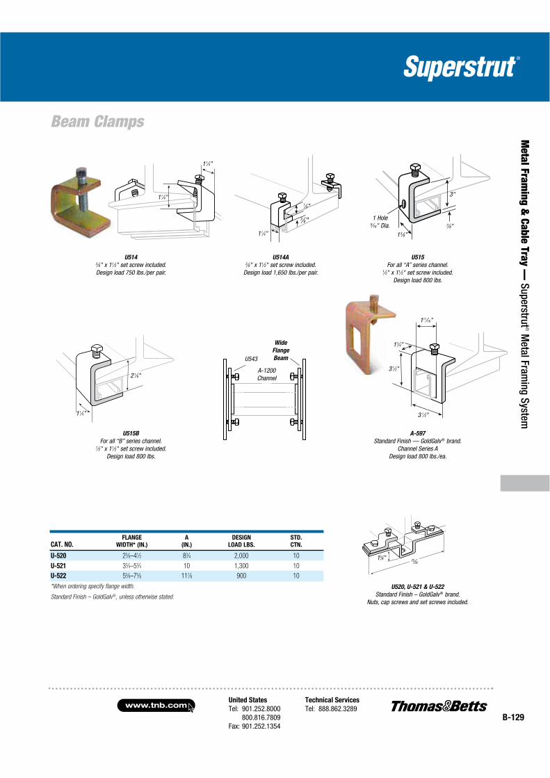
U5143⁄8" x 11⁄2" set screw included.Design load 750 lbs./per pair.
11⁄4"
11⁄4"
U514A3⁄8" x 11⁄2" set screw included.
Design load 1,650 lbs./per pair.
3⁄8"
7⁄8"
11⁄4"
U515
For all “A” series channel.1⁄2" x 11⁄2" set screw included.
Design load 800 lbs.
15⁄8"
3⁄8"1 Hole
9⁄16" Dia.
3"
U515B
For all “B” series channel.1⁄2" x 11⁄2" set screw included.
Design load 800 lbs.
11⁄4"
2 1⁄8"
Wide
Flange
Beam
A-1200Channel
U543
A-597
Standard Finish — GoldGalv ® brand.Channel Series A
Design load 800 lbs./ea.
CAT. NO.FLANGE
WIDTH* (IN.)
A
(IN.)
DESIGN
LOAD LBS.
STD.
CTN.
U-520 23⁄8–41⁄2 83⁄4 2,000 10
U-521 33⁄4–53⁄4 10 1,300 10
U-522 55⁄8–75⁄8 117⁄8 900 10
*When ordering specify flange width.
Standard Finish – GoldGalv®, unless otherwise stated.
U520, U-521 & U-522
Standard Finish – GoldGalv ® brand.Nuts, cap screws and set screws included.
25⁄3215⁄8"
13⁄4"
3 1⁄2"
3 1⁄2"
111⁄16"
www.tnb.comUnited States
Tel: 901.252.8000800.816.7809
Fax: 901.252.1354
Technical Services
Tel: 888.862.3289B-130
Met
al F
ram
ing
& C
able
Tra
y —
Sup
erst
rut®
Met
al F
ram
ing
Syst
em
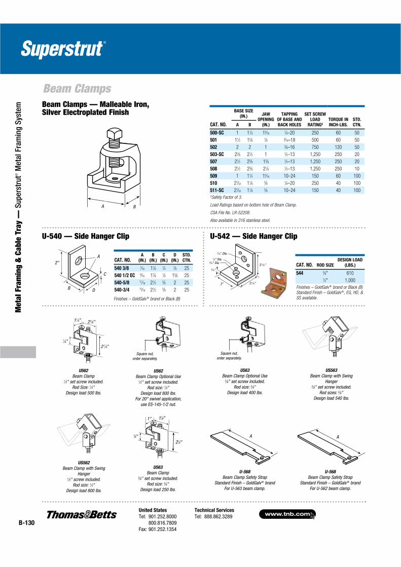
Beam Clamps Beam Clamps — Malleable Iron, Silver Electroplated Finish
CAT. NO.
BASE SIZE
(IN.) JAW
OPENING
(IN.)
TAPPING
OF BASE AND
BACK HOLES
SET SCREW
LOAD
RATING‡
TORQUE IN
INCH-LBS.
STD.
CTN.A B
500-SC 1 11⁄4 15⁄161⁄4–20 250 60 50
501 11⁄2 15⁄8 7⁄8 5⁄16–18 500 60 50
502 2 2 1 3⁄8–16 750 120 50
503-SC 25⁄8 21⁄2 1 1⁄2–13 1,250 250 20
507 21⁄2 23⁄8 13⁄8 1⁄2–13 1,250 250 20
508 21⁄2 23⁄8 21⁄8 1⁄2–13 1,250 250 10
509 1 11⁄4 15⁄16 10–24 150 60 100
510 27⁄32 11⁄8 5⁄8 1⁄4–20 250 40 100
511-SC 27⁄32 11⁄8 5⁄8 10–24 150 40 100‡Safety Factor of 3.
Load Ratings based on bottom hole of Beam Clamp.
CSA File No. LR-52208.
Also available in 316 stainless steel.
CAT. NO.A
(IN.)
B
(IN.)
C
(IN.)
D
(IN.)
STD.
CTN.
540 3/8 7⁄16 17⁄8 1⁄4 7⁄8 25
540 1/2 EC 9⁄16 17⁄8 1⁄4 15⁄8 25
540-5/8 11⁄16 21⁄2 3⁄8 2 25
540-3/4 13⁄16 21⁄2 3⁄8 2 25
Finishes – GoldGalv ® brand or Black (B)
7⁄16" Dia.1⁄4" Dia.
9⁄16" Dia. 2 1⁄16"
2 1⁄16"2"
3⁄16"
2"A
C
DB
U562
Beam Clamp Optional Use 1⁄2" set screw included.
Rod size: 1⁄2"Design load 800 lbs.
For 20° swivel application, use ES-145-1/2 nut.
U562
Beam Clamp1⁄2" set screw included.
Rod Size: 1⁄2"Design load 500 lbs.
7⁄8"2 7⁄8"
2 5⁄8"11⁄4"
US562
Beam Clamp with Swing Hanger
1⁄2" screw included.Rod size: 1⁄2"
Design load 800 lbs.
US563
Beam Clamp with Swing Hanger
3⁄8" set screw included. Rod sizes: 3⁄8"
Design load 540 lbs.
U563
Beam Clamp3⁄8" set screw included.
Rod size: 3⁄8"Design load 250 lbs.
21⁄4"
3⁄4"
17⁄8"1"
U563
Beam Clamp Optional Use 3⁄8" set screw included.
Rod size: 3⁄8"Design load 400 lbs.
A
U-568
Beam Clamp Safety StrapStandard Finish – GoldGalv ® brand
For U-562 beam clamp.
U-568
Beam Clamp Safety StrapStandard Finish – GoldGalv ® brand
For U-563 beam clamp.
A
A B
U-540 — Side Hanger Clip U-542 — Side Hanger Clip
CAT. NO. ROD SIZE
DESIGN LOAD
(LBS.)
544 3⁄8" 6101⁄2" 1,000
Finishes – GoldGalv ® brand or Black (B)
Standard Finish – GoldGalv ®, EG, HD, &
SS available.
Square nut, order separately.
Square nut, order separately.
United States
Tel: 901.252.8000800.816.7809
Fax: 901.252.1354
Technical Services
Tel: 888.862.3289www.tnb.com
B-131
Metal Fram
ing & Cable Tray —
Superstrut® M
etal Framing System
Beam Clamps
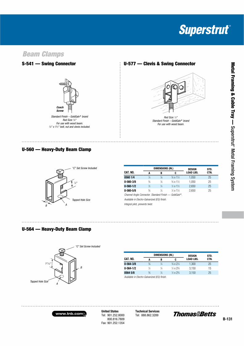
Standard Finish – GoldGalv ® brand Rod Size: 3⁄8"
For use with wood beam. 3⁄8" x 13⁄4" bolt, nut and clevis included.
Coach
Screw
Rod Size: 1⁄2"Standard Finish – GoldGalv ® brand
For use with wood beam.
“C” Set Screw Included
Tapped Hole Size
AB
7⁄8"
CAT. NO.
DIMENSIONS (IN.) DESIGN
LOAD LBS.
STD.
CTN.A B C
U560 1/4 1⁄4 1⁄8 3⁄8 x 11⁄2 1,050 25
U-560-3/8 3⁄8 1⁄8 3⁄8 x 11⁄2 1,050 25
U-560-1/2 1⁄2 1⁄4 1⁄2 x 11⁄2 2,650 25
U-560-5/8 5⁄8 1⁄4 1⁄2 x 11⁄2 2,650 25
Channel Angle Connector. Standard Finish — GoldGalv ®.
Available in Electro-Galvanized (EG) finish.
Integral pilot, prevents twist.
U-560 — Heavy-Duty Beam Clamp
“C” Set Screw Included
Tapped Hole Size
B
A
1 21⁄32"
CAT. NO.
DIMENSIONS (IN.) DESIGN
LOAD LBS.
STD.
CTN.A B C
U-564-3/8 3⁄8 1⁄4 3⁄8 x 21⁄4 1,300 25
U-564-1/2 1⁄2 1⁄4 1⁄2 x 23⁄4 3,150 15
U564 5/8 5⁄8 1⁄4 1⁄2 x 23⁄4 3,150 25
Available in Electro-Galvanized (EG) finish.
U-564 — Heavy-Duty Beam Clamp
S-541 — Swing Connector U-577 — Clevis & Swing Connector

www.tnb.comUnited States
Tel: 901.252.8000800.816.7809
Fax: 901.252.1354
Technical Services
Tel: 888.862.3289B-132
Met
al F
ram
ing
& C
able
Tra
y —
Sup
erst
rut®
Met
al F
ram
ing
Syst
em
Beam Clamps
For use with E-231 and E-232 clamps when hanger rod is not in straight through position.
A
Clamps to I-beams, channels, angles and column
Two sizes are available, one for 3⁄8" and the other for 1⁄2" hanger rod
Each takes flanges up to .8" thickness
E-233 — Anchor Clip
CAT. NO.ROD
SIZE (IN.)
MAX. BEAM WIDTH
“A” (IN.)
FOR USE
WITH
WT.
LBS./C
E-233-3/8-6 3⁄8 6 E-231-3/8 or 20
E-233-3/8-10 3⁄8 10 E-232-3/8 33
E-233-1/2-6 1⁄2 6 E-231-1/2 or 26
E-233-1/2-10 1⁄2 10 E-232-1/2 37
Anchor Clips should be used when clamps are subject to excessive vibration. To obtain
the correct size clips, add 1 inch to the flange width. If length required is not standard,
order next largest standard length.
GoldGalv ® finish.
CAT. NO.
DIMENSIONS (IN.) WT.
LBS./CA B C
3⁄8" or 1⁄2" Rod
*E-231-3/8 21⁄2 1 7⁄8 31
**E-231-1/2 3 19⁄3215⁄16 53
Assembly requires two H-116-C (3⁄8") or two H-116-D (1⁄2") square nuts to attach hanger rod.
1⁄2" steel.
* Load rating of 500 lbs. with a safety factor of 3.
** Load rating of 800 lbs. with a safety factor of 3.
Standard Finish – GoldGalv ®, unless otherwise stated.
A
B
C
E-231 — Structural Steel Clamp
CAT. NO.DIAMETER
FOR ROD (IN.)
DIMENSIONS (IN.) WT.
LBS./CA B C
3⁄8" or 1⁄2" Rod
*E-232-3/8 3⁄8 9⁄167⁄16 1 48
**E-232-1/2 1⁄2 7⁄8 29⁄64 15⁄8 76
* Load rating of 400 lbs. with a safety factor of 3.
** Load rating of 550 lbs. with a safety factor of 3.
GoldGalv ® finish.
E-231 clamp with swing connector
Affords a convenient method of attaching to angled beams A
B
C
E-232 — Clamp with Swing Connector
United States
Tel: 901.252.8000800.816.7809
Fax: 901.252.1354
Technical Services
Tel: 888.862.3289www.tnb.com
B-133
Metal Fram
ing & Cable Tray —
Superstrut® M
etal Framing System
Beam Clamps
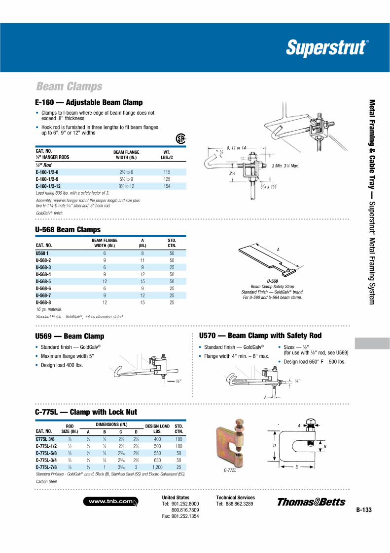
CAT. NO.1⁄2" HANGER RODS
BEAM FLANGE
WIDTH (IN.)
WT.
LBS./C
1⁄2" Rod
E-160-1/2-6 21⁄2 to 6 115
E-160-1/2-9 51⁄2 to 9 125
E-160-1/2-12 81⁄2 to 12 154
Load rating 800 lbs. with a safety factor of 3.
Assembly requires hanger rod of the proper length and size plus
two H-114-D nuts 3⁄16" steel and 1⁄2" hook rod.
GoldGalv ® finish.
Clamps to I-beam where edge of beam flange does not exceed .8" thickness
Hook rod is furnished in three lengths to fit beam flanges up to 6", 9" or 12" widths
8, 11 or 141⁄2
2 1⁄8
3⁄16 x 11⁄2
3 Min. 3 5⁄8 Max.
E-160 — Adjustable Beam Clamp
CAT. NO.BEAM FLANGE
WIDTH (IN.)
A
(IN.)
STD.
CTN.
U568 1 6 8 50
U-568-2 9 11 50
U-568-3 6 9 25
U-568-4 9 12 50
U-568-5 12 15 50
U-568-6 6 9 25
U-568-7 9 12 25
U-568-8 12 15 25
16 ga. material.
Standard Finish – GoldGalv ®, unless otherwise stated.
U-568 Beam Clamps
A
U-568
Beam Clamp Safety StrapStandard Finish — GoldGalv ® brand. For U-560 and U-564 beam clamp.
U569 — Beam ClampStandard finish — GoldGalv®
Maximum flange width 5"
Design load 400 lbs.
U570 — Beam Clamp with Safety Rod
3⁄8" 3⁄8"
A
CAT. NO.ROD
SIZE (IN.)
DIMENSIONS (IN.) DESIGN LOAD
LBS.
STD.
CTN.A B C D
C775L 3/8 3⁄8 3⁄8 3⁄4 23⁄8 23⁄8 400 100
C-775L-1/2 1⁄2 3⁄8 3⁄4 23⁄8 23⁄8 500 100
C-775L-5/8 5⁄8 1⁄2 3⁄4 25⁄16 23⁄8 550 50
C-775L-3/4 3⁄4 5⁄8 3⁄4 25⁄16 23⁄8 630 50
C-775L-7/8 7⁄8 3⁄4 1 35⁄16 3 1,200 25
Standard Finishes - GoldGalv® brand, Black (B), Stainless Steel (SS) and Electro-Galvanized (EG).
Carbon Steel.
C-775L
A
B
C
D
C-775L — Clamp with Lock Nut
Standard finish — GoldGalv®
Flange width 4" min. – 8" max.
Sizes — 1⁄2"(for use with 3⁄8" rod, see U569)
Design load 650° F – 500 lbs.

www.tnb.comUnited States
Tel: 901.252.8000800.816.7809
Fax: 901.252.1354
Technical Services
Tel: 888.862.3289B-134
Met
al F
ram
ing
& C
able
Tra
y —
Sup
erst
rut®
Met
al F
ram
ing
Syst
em
Beam Clamps
M-777 — Steel Top Beam Clamp
C-777 — Steel Top Beam Clamp & C-778 — Steel Wide JawTop Beam Clamp
M-775L — Clamp with Lock Nut
M-778 — Steel Wide Jaw Top Clamp
CAT. NO.ROD SIZE
A (IN.) B (IN.) C (IN.)
DESIGN
LOAD LBS.
STD.
CTN.
M-775L-3/8 3⁄8 3⁄4 13⁄4 400 100
M-775L-1/2 1⁄2 3⁄4 13⁄4 400 100
M-775L-5/8 5⁄8 3⁄4 2 440 50
M-775L-3/4 3⁄4 3⁄4 2 500 50
Available in Electro-Galvanized (EG) or Black (B).M-775L
B C
A
ROD SIZE A (IN.) DESIGN LOAD LBS.
3⁄8 3501⁄2 4705⁄8 5503⁄4 7007⁄8 1,000
3⁄4"
A
11⁄4"
A
C-777, C-788
AB
C
D
E
CAT. NO.ROD SIZE
A (IN.)
PIPE
SIZE
DIMENSIONS (IN.)DESIGN
LOAD LBS.
STD.
CTN.B C D E F
C777 3/8 3⁄8 1⁄2–4 13⁄163⁄4 1 7⁄16 1 900 100
C-777-1/2 1⁄2 5–8 11⁄2 3⁄4 1 9⁄16 11⁄4 2,430 50
C-778-3/8 3⁄8 1⁄2–4 13⁄16 11⁄4 1 7⁄16 1 900 100
C-778-1/2 1⁄2 5–8 11⁄2 11⁄4 1 9⁄16 11⁄4 2,430 50
Standard Finish – GoldGalv®, Black (B) and Electro-Galvanized (EG).
Top Beam C-Clamp
Rod Size: 3⁄8", 1⁄2", 5⁄8" and 3⁄4"
Available in Electro-Galvanized (EG) or Black (B) Malleable Iron
Provides clamping under roof installations with bar joisttype construction
Order by Cat. No. and rod sizeM-778
M-777
Junior Top Beam C-Clamp
Standard finish is Gold-Galv®
Available in Electro-Galvanized (EG) or Black (B) Malleable Iron
Provides clamping under roof installations with bar joist construction (max. joist thickness 5⁄8")
Order by Cat. No., rod size
ROD SIZE A (IN.) DESIGN LOAD LBS.
3⁄8 4001⁄2 5005⁄8 8503⁄4 900

United States
Tel: 901.252.8000800.816.7809
Fax: 901.252.1354
Technical Services
Tel: 888.862.3289www.tnb.com
B-135
Metal Fram
ing & Cable Tray —
Superstrut® M
etal Framing System
Beam Clamps
EC Clamp — Malleable Iron
For mounting pipe or conduit vertically across the beam
CAT. NO.& SIZE
DIMENSIONS (IN.)
STD.
CTN.
CAT. NO.& SIZE
DIMENSIONS (IN.)
STD.
CTN.
O.D. OF
CONDUIT
OR PIPE
NOM.
CONDUIT
PIPE SIZE
O.D. OF
CONDUIT
OR PIPE
NOM.
CONDUIT
PIPE SIZE
RCS-1/2 .840 1⁄2 50 EC-1/2 .840 1⁄2 50
RCS-3/4 1.050 3⁄4 50 EC-3/4 1.050 3⁄4 50
RCS-1 1.315 1 50 EC-1 1.315 1 25
RCS-1-1/4 1.660 11⁄4 50 EC-1-1/4 1.660 11⁄4 25
RCS-1-1/2 1.900 11⁄2 50 EC-1-1/2 1.900 11⁄2 25
RCS-2 2.375 2 50 EC-2 2.375 2 25
RC-3/8 .675 3⁄8 50 EC-2-1/2 2.875 21⁄2 10
RC-1/2 .840 1⁄2 50 EC-3 3.500 3 10
RC-3/4 1.050 3⁄4 50 PC-3/8 .675 3⁄8 50
RC-1 1.315 1 50 PC 1/2 .840 1⁄2 50
RC-1-1/4 1.660 11⁄4 50 PC-3/4 1.050 3⁄4 50
RC-1-1/2 1.900 11⁄2 50 PC-1 1.315 1 50
RC-2-SC 2.375 2 50 PC-1-1/4 1.660 11⁄4 25
RC-2-1/2 2.875 21⁄2 25 PC-1-1/2 1.900 11⁄2 25
RC-3 3.500 3 25 PC-2 2.375 2 25
RC-3-1/2 4.000 31⁄2 25 PC-2-1/2 2.875 21⁄2 25
RC-4-SC 4.500 4 20 PC-3 3.500 3 10
PC-3-1/2 4.00 31⁄2 10
PC-4 4.500 4 10
Pipe Supports
RC Clamp — Malleable Iron
RCS Clamp — Steel
For mounting pipe or conduit at right angles to the beam
PC Clamp —Malleable Iron
For mounting pipe or conduit parallel to the beam
CONDUIT SIZE MAX. BEAM C-247 FLANGE C-248 THICKNESS C-249
1⁄2 5⁄8 13⁄4 7⁄16
3⁄4 11⁄2
1 1⁄2 11⁄4
11⁄4 1
11⁄2 5⁄8
Dim. A 21⁄4 2 9⁄16 31⁄4
Dim. B 13⁄8 13⁄4 21⁄2
Dim. C 23⁄4 3 4
Dim. D 9⁄169⁄16
5⁄8
Per Carton 100 50 50
Wt. in lbs./C 33 36 59
Standard Finish – GoldGalv ®, unless otherwise stated.
A
B
C
D
1⁄8
A versatile clamp for attaching conduit to any type of beam, channel, angle or column
Designed to hold the conduit snug against the support with conduit either parallel or at right angle to it
The case-hardened set screw bites into the structural memberfor maximum security 1⁄8" steel
C-247, C-248 & C-249 — Steel Conduit Clamps
Three types of pipe clamps are available to provide right angle, vertical and parallel attachment to a beam. Types RC, EC and PC are malleable iron clamps with an edge that grips the structural member for maximum holding power when tightened.
Type RCS clamps are all steel, providing two bearing surfaces for strong attachment for mounting pipe or conduit at right angles to the beam.
All parts are electrogalvanized, including the threads. The clamps are designed for clamping to a wide variety of beam thicknesses and tapers. Can be installed using only a wrench.
Use SS316 suffix for 316 Stainless Steel
Use HDG suffix for hot-dip galvanized
Use SS316 suffix for 316 Stainless Steel
Use HDG suffix for hot-dip galvanized
Use SS316 suffix for 316 Stainless Steel
Use HDG suffix for hot-dip galvanized

www.tnb.comUnited States
Tel: 901.252.8000800.816.7809
Fax: 901.252.1354
Technical Services
Tel: 888.862.3289B-136
Met
al F
ram
ing
& C
able
Tra
y —
Sup
erst
rut®
Met
al F
ram
ing
Syst
em
Pipe Straps, Conduit Clamps and Hangers
GoldGalv® Outperforms Copper Plated
In a test conforming to ASTM G-87-84, also known as the Kesternich Test, Superstrut’s GoldGalv® electrogalvanized zinc trivalent chromium finish achieved superior corrosion resistance in comparison to copper plated.
Performed and certified by an independent testing laboratory, the stringent Kesternich test is equivalent to an acid rain environment. The test procedure exposes subject material to condensed moisture containing harsh sulfur dioxide (S02) which accelerates the aging process. During the series of test time cycles, the material is thoroughly inspected for signs and progression of damaging red rust.
The first test series conducted included various light-duty adjustable clevis hangers assembled to copper tubing. The GoldGalv® finish exhibited five times the red rust resistance as compared to copper plated.
The second test series was performed on various O.D. pipe straps attached to copper tubing and continuous slot channel. GoldGalv® achieved greater red dust resistance by seven times over copper plating.
Once tests were completed, all copper tubes were split open and inspected for signs of electrolysis. The copper tubes showed minimal deterioration as a result of the test and no indication of electrolysis occurrence when attached to material with GoldGalv® finish.
GoldGalv® hardware finish is standard for all Superstrut® products. This is a multi-process finish of electro-plated zinc, followed by gold-colorized trivalent chromium to give excellent corrosion resistance and a superior paint base. See pages B-106–B-107 for a complete description of the GoldGalv® hardware finish. GoldGalv® hardware will be furnished if no other finish is specified.
Materials
Most products are manufactured from hot-rolled carbon steel bars or hot-rolled strip steel. Pipe rollers are cast iron. Products which are copper plated carry the letter “T” in the prefix.
Design Loads
Where design loads are indicated, they provide for a safety factor of 3 in conformance with the “AMERICAN STANDARD CODE FOR PRESSURE PIPING.”
Hanger Design
Pipe hangers are of advanced design and afford a new and better way of ordinary use.
Standard Dimensions
The following, except where noted, apply to all beam clamp fittings.
Hole Size: 9⁄16" diameter
Material: 15⁄8" wide
Material: 1⁄4" thick
Excellent Corrosion Resistance and a Superior Paint Base
ASTM G-87-84 Corrosion Test Results
FINISH
INITIAL
RED RUST
50%
RED RUST
100%
RED RUST
Test Series I: Light-Duty Adjustable Clevis Hanger
GoldGalv® 120 hours 216 hours *Never obtained
Copper Plated 24 hours 48 hours 72 hours
Test Series II: O.D. Pipe Straps
GoldGalv® 168 hours 192 hours 240 hours
Copper plated 24 hours 48 hours 168 hours
*Test series ended after 360 hours.
Standard Finish – GoldGalv ®, unless otherwise stated.
United States
Tel: 901.252.8000800.816.7809
Fax: 901.252.1354
Technical Services
Tel: 888.862.3289www.tnb.com
B-137
Metal Fram
ing & Cable Tray —
Superstrut® M
etal Framing System
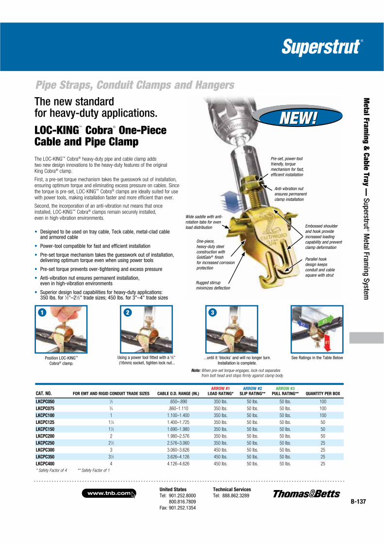
Pipe Straps, Conduit Clamps and HangersThe new standard for heavy-duty applications.
LOC-KING™ Cobra® One-Piece Cable and Pipe ClampThe LOC-KING™ Cobra® heavy-duty pipe and cable clamp adds two new design innovations to the heavy-duty features of the original King Cobra® clamp.
First, a pre-set torque mechanism takes the guesswork out of installation, ensuring optimum torque and eliminating excess pressure on cables. Since the torque is pre-set, LOC-KING™ Cobra® clamps are ideally suited for use with power tools, making installation faster and more efficient than ever.
Second, the incorporation of an anti-vibration nut means that once installed, LOC-KING™ Cobra® clamps remain securely installed,even in high-vibration environments.
Designed to be used on tray cable, Teck cable, metal-clad cable and armored cable
Power-tool compatible for fast and efficient installation
Pre-set torque mechanism takes the guesswork out of installation, delivering optimum torque even when using power tools
Pre-set torque prevents over-tightening and excess pressure
Anti-vibration nut ensures permanent installation, even in high-vibration environments
Superior design load capabilities for heavy-duty applications:350 lbs. for 1⁄2"–21⁄2" trade sizes; 450 lbs. for 3"–4" trade sizes
Position LOC-KING™
Cobra® clamp.Using a power tool fitted with a 5⁄8" (16mm) socket, tighten lock nut...
See Ratings in the Table Below...until it ‘blocks’ and will no longer turn. Installation is complete.
Note: When pre-set torque engages, lock-nut separates
from bolt head and stops firmly against clamp body.
321
CAT. NO. FOR EMT AND RIGID CONDUIT TRADE SIZES CABLE O.D. RANGE (IN.)
ARROW #1
LOAD RATING*
ARROW #2
SLIP RATING**
ARROW #3
PULL RATING** QUANTITY PER BOX
LKCPC050 1⁄2 .650–.890 350 lbs. 50 lbs. 50 lbs. 100
LKCPC075 3⁄4 .860–1.110 350 lbs. 50 lbs. 50 lbs. 100
LKCPC100 1 1.100–1.400 350 lbs. 50 lbs. 50 lbs. 100
LKCPC125 11⁄4 1.400–1.725 350 lbs. 50 lbs. 50 lbs. 50
LKCPC150 11⁄2 1.690–1.980 350 lbs. 50 lbs. 50 lbs. 50
LKCPC200 2 1.980–2.576 350 lbs. 50 lbs. 50 lbs. 50
LKCPC250 21⁄2 2.576–3.060 350 lbs. 50 lbs. 50 lbs. 25
LKCPC300 3 3.060–3.626 450 lbs. 50 lbs. 50 lbs. 25
LKCPC350 31⁄2 3.626–4.126 450 lbs. 50 lbs. 50 lbs. 25
LKCPC400 4 4.126–4.626 450 lbs. 50 lbs. 50 lbs. 25
* Safety Factor of 4 ** Safety Factor of 1
Pre-set, power-tool friendly, torque mechanism for fast, efficient installation
Anti-vibration nut ensures permanent clamp installation
Wide saddle with anti-rotation tabs for even load distribution
One-piece, heavy-duty steel construction with GoldGalv® finish for increased corrosion protection
Rugged stirrup minimizes deflection
Embossed shoulder and hook provide increased loading capability and prevent clamp deformation
Parallel hook design keeps conduit and cable square with strut
NEW!NEW!
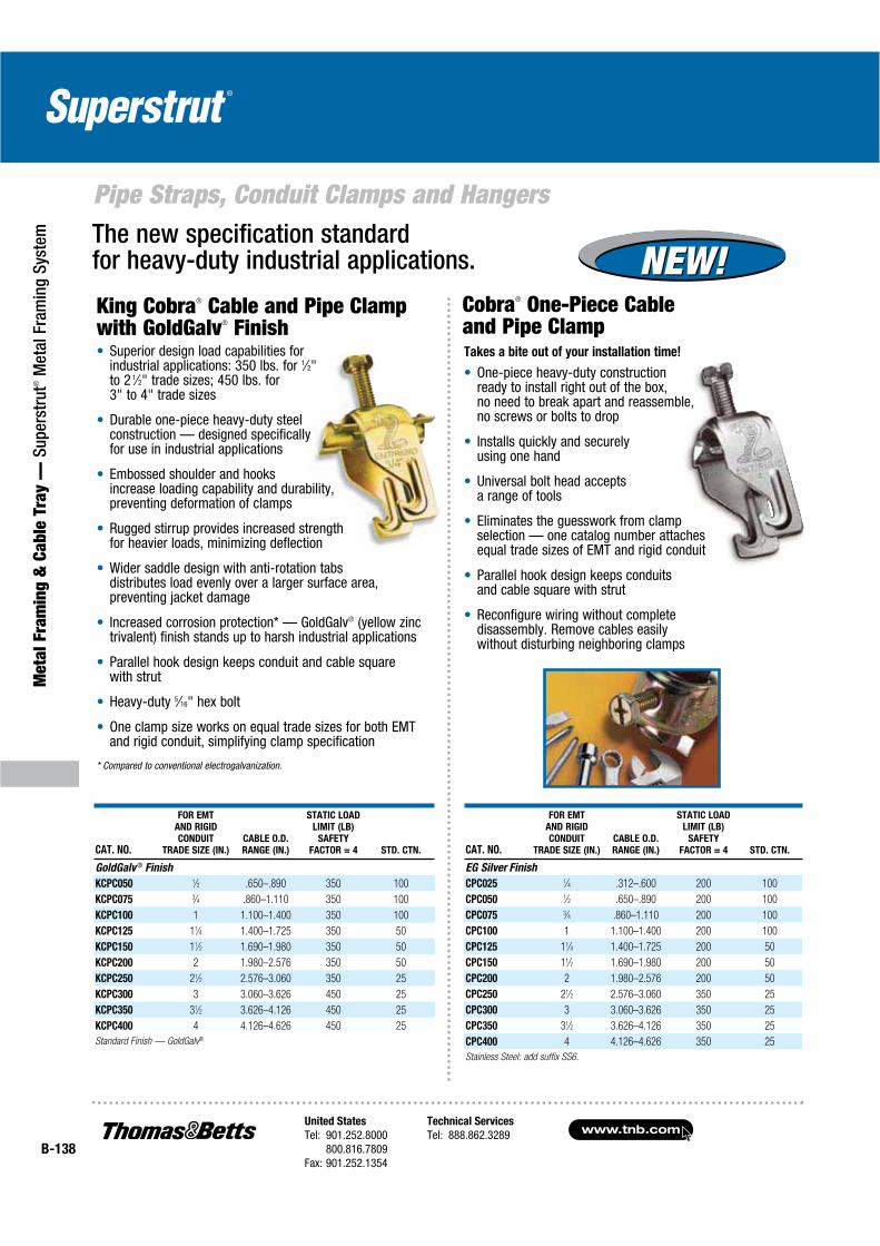
www.tnb.comUnited States
Tel: 901.252.8000800.816.7809
Fax: 901.252.1354
Technical Services
Tel: 888.862.3289B-138
Pipe Straps, Conduit Clamps and Hangers
Met
al F
ram
ing
& C
able
Tra
y —
Sup
erst
rut®
Met
al F
ram
ing
Syst
em
NEW!NEW!
CAT. NO.
FOR EMT
AND RIGID
CONDUIT
TRADE SIZE (IN.)
CABLE O.D.
RANGE (IN.)
STATIC LOAD
LIMIT (LB)
SAFETY
FACTOR = 4 STD. CTN.
EG Silver Finish
CPC025 1⁄4 .312–.600 200 100
CPC050 1⁄2 .650–.890 200 100
CPC075 3⁄4 .860–1.110 200 100
CPC100 1 1.100–1.400 200 100
CPC125 11⁄4 1.400–1.725 200 50
CPC150 11⁄2 1.690–1.980 200 50
CPC200 2 1.980–2.576 200 50
CPC250 21⁄2 2.576–3.060 350 25
CPC300 3 3.060–3.626 350 25
CPC350 31⁄2 3.626–4.126 350 25
CPC400 4 4.126–4.626 350 25
Stainless Steel: add suffix SS6.
CAT. NO.
FOR EMT
AND RIGID
CONDUIT
TRADE SIZE (IN.)
CABLE O.D.
RANGE (IN.)
STATIC LOAD
LIMIT (LB)
SAFETY
FACTOR = 4 STD. CTN.
GoldGalv ® Finish
KCPC050 1⁄2 .650–.890 350 100
KCPC075 3⁄4 .860–1.110 350 100
KCPC100 1 1.100–1.400 350 100
KCPC125 11⁄4 1.400–1.725 350 50
KCPC150 11⁄2 1.690–1.980 350 50
KCPC200 2 1.980–2.576 350 50
KCPC250 21⁄2 2.576–3.060 350 25
KCPC300 3 3.060–3.626 450 25
KCPC350 31⁄2 3.626–4.126 450 25
KCPC400 4 4.126–4.626 450 25
Standard Finish — GoldGalv®
Takes a bite out of your installation time!
One-piece heavy-duty construction ready to install right out of the box, no need to break apart and reassemble, no screws or bolts to drop
Installs quickly and securely using one hand
Universal bolt head accepts a range of tools
Eliminates the guesswork from clamp selection — one catalog number attaches equal trade sizes of EMT and rigid conduit
Parallel hook design keeps conduits and cable square with strut
Reconfigure wiring without complete disassembly. Remove cables easily without disturbing neighboring clamps
Cobra® One-Piece Cableand Pipe Clamp
The new specification standard for heavy-duty industrial applications.
King Cobra® Cable and Pipe Clamp with GoldGalv® Finish
Superior design load capabilities for industrial applications: 350 lbs. for 1⁄2"to 2 1⁄2" trade sizes; 450 lbs. for 3" to 4" trade sizes
Durable one-piece heavy-duty steel construction — designed specifically for use in industrial applications
Embossed shoulder and hooks increase loading capability and durability, preventing deformation of clamps
Rugged stirrup provides increased strength for heavier loads, minimizing deflection
Wider saddle design with anti-rotation tabsdistributes load evenly over a larger surface area, preventing jacket damage
Increased corrosion protection* — GoldGalv® (yellow zinc trivalent) finish stands up to harsh industrial applications
Parallel hook design keeps conduit and cable squarewith strut
Heavy-duty 5⁄16" hex bolt
One clamp size works on equal trade sizes for both EMT and rigid conduit, simplifying clamp specification
* Compared to conventional electrogalvanization.

United States
Tel: 901.252.8000800.816.7809
Fax: 901.252.1354
Technical Services
Tel: 888.862.3289www.tnb.com
B-139
Pipe Straps, Conduit Clamps and Hangers
Metal Fram
ing & Cable Tray —
Superstrut® M
etal Framing System
Pre-assembled for easy handling and sorting.
Superstrut® Pipe Straps
Design Loads
Superstrut® Pipe Straps are designed to be twist inserted anywhere along the slot side of the channel. Pipes can be placed as closely as pipe couplings permit.
Some unique features of the straps include:
Bolt head is combination slot and hex headfor flexibility of attachment
Square nut is captivated on the shoulder for easy one-handed tightening
Straps are interchangeable with 11⁄2" strut for broader application
Straps are shipped assembled so countingand sorting are easier
Pipe or conduit sizes are shown on the strapfor easy identification
All Superstrut® Straps are preassembled for easy handling and sorting
CAT. NO.EMT
SIZE (IN.)
O.D.
SIZE (IN.)
STEEL STRAP
THICKNESS
DESIGN LOAD
(LBS.)
STD.
CTN.
700 3/8-STR 3⁄8 .577 14 ga. 750 100
700-1/2-STR 1⁄2 .706 14 ga. 750 100
700-3/4-STR 3⁄4 .922 14 ga. 750 100
700-1-STR 1 1.163 14 ga. 750 100
700-1-1/4-STR 11⁄4 1.510 14 ga. 750 50
700-1-1/2-STR 11⁄2 1.740 12 ga. 800 50
700-2-STR 2 2.197 12 ga. 800 50
Standard Finish – GoldGalv®
700 — Superstrut® Straps for EMT
CAT. NO.TUBING O.D.
(IN.)
STEEL STRAP
THICKNESS
DESIGN LOAD
(LBS.)
STD.
CTN
701-1/4 1⁄4 14 ga. 750 100
701-3/8 3⁄8 14 ga. 750 100
701-1/2-STR 1⁄2 14 ga. 750 100
701-5/8 5⁄8 14 ga. 750 100
701-3/4 3⁄4 14 ga. 750 100
701-7/8 7⁄8 14 ga. 750 100
701-1-STR 1 14 ga. 750 50
701-1-1/8 11⁄8 14 ga. 1,000 100
701-1-1/4 11⁄4 14 ga. 1,000 25
701-1-3/8 13⁄8 14 ga. 1,000 100
701-1-1/2 11⁄2 14 ga. 1,000 25
701-1-5/8 15⁄8 14 ga. 1,000 100
701-1-3/4 13⁄4 12 ga. 1,000 25
701-1-7/8 17⁄8 12 ga. 1,000 50
701-2 2 12 ga. 1,000 50
701-2-1/8 21⁄8 12 ga. 1,300 50
701-2-1/4 21⁄4 12 ga. 1,300 25
701-2-3/8 23⁄8 12 ga. 1,300 25
701-2-1/2 21⁄2 12 ga. 1,300 25
701-2-5/8 25⁄8 12 ga. 1,300 50
(continued on following page)
701 — Superstrut® Straps for O.D. Tubing
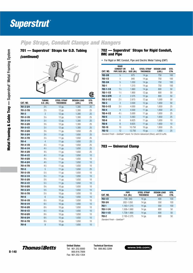
www.tnb.comUnited States
Tel: 901.252.8000800.816.7809
Fax: 901.252.1354
Technical Services
Tel: 888.862.3289B-140
Pipe Straps, Conduit Clamps and Hangers
Met
al F
ram
ing
& C
able
Tra
y —
Sup
erst
rut®
Met
al F
ram
ing
Syst
em
CAT. NO.TUBING
O.D. (IN.)
STEEL STRAP
THICKNESS
DESIGN LOAD
(LBS.)
STD.
CTN
701-2-3/4 23⁄4 12 ga. 1,300 25
701-2-7/8 27⁄8 12 ga. 1,300 25
701-3 3 12 ga. 1,300 25
701-3-1/8 31⁄8 12 ga. 1,300 25
701-3-1/4 31⁄4 12 ga. 1,300 25
701-3-3/8 33⁄8 12 ga. 1,300 25
701-3-1/2 31⁄2 12 ga. 1,300 25
701-3-5/8 35⁄8 11 ga. 1,650 25
701-3-3/4 33⁄4 11 ga. 1,650 25
701-3-7/8 37⁄8 11 ga. 1,650 25
701-4 4 11 ga. 1,650 25
701-4-1/8 41⁄8 11 ga. 1,650 25
701-4-1/4 41⁄4 11 ga. 1,650 25
701-4-3/8 43⁄8 11 ga. 1,650 25
701-4-1/2 41⁄2 11 ga. 1,650 10
701-4-5/8 45⁄8 11 ga. 1,650 10
701-4-3/4 43⁄4 11 ga. 1,650 10
701-4-7/8 47⁄8 11 ga. 1,650 10
701-5 5 11 ga. 1,650 25
701-5-1/8 51⁄8 11 ga. 1,650 10
701-5-1/4 51⁄4 11 ga. 1,650 10
701-5-3/8 53⁄8 11 ga. 1,650 10
701-5-1/2 51⁄2 11 ga. 1,650 10
701-5-5/8 55⁄8 10 ga. 1,650 10
701-5-3/4 53⁄4 10 ga. 1,650 10
701-5-7/8 57⁄8 10 ga. 1,650 10
701-6 6 10 ga. 1,650 10
701-6-1/8 61⁄8 10 ga. 1,650 10
701-6-1/4 61⁄4 10 ga. 1,650 10
701-6-3/8 63⁄8 10 ga. 1,650 10
701-6-1/2 61⁄2 10 ga. 1,650 10
701-6-5/8 65⁄8 10 ga. 1,650 10
701-6-3/4 63⁄4 10 ga. 1,650 10
701-6-7/8 67⁄8 10 ga. 1,650 10
701-8 8 10 ga. 1,650 10
701 — Superstrut® Straps for O.D. Tubing
(continued)
CAT. NO.
RIGID
CONDUIT OR
PIPE SIZE (IN.)
O.D.
SIZE (IN.)
STEEL STRAP
THICKNESS
DESIGN LOAD
(LBS.)
STD.
CTN.
702-3/8 3⁄8 .675 14 ga. 750 100
702-1/2 1⁄2 .840 14 ga. 750 100
702-3/4 3⁄4 1.050 14 ga. 750 100
702-1 1 1.315 14 ga. 750 100
702-1-1/4 11⁄4 1.660 14 ga. 800 50
702-1-1/2 11⁄2 1.900 12 ga. 800 50
702-2-STR 2 2.375 12 ga. 800 50
702-2-1/2 21⁄2 2.875 12 ga. 1,000 50
702-3 3 3.500 12 ga. 1,650 50
702-3-1/2 31⁄2 4.000 11 ga. 1,650 25
702-4 4 4.500 11 ga. 1,650 25
702-4-1/2 41⁄2 5.000 11 ga. 1,650 25
702-5 5 5.563 11 ga. 1,650 25
702-6 6 6.625 11 ga. 1,650 10
702-8 8 8.625 11 ga. 1,650 10
702-10 10 10.750 10 ga. 1,650 25
702-12 12 12.750 10 ga. 1,650 25
Standard Finish – GoldGalv ® brand. For Electro-Galvanized (Silver), add EG suffix.
For Rigid or IMC Conduit, Pipe and Electric Metal Tubing (EMT)
702 — Superstrut® Straps for Rigid Conduit, IMC and Pipe
CAT. NO.PIPE
O.D. (IN.)
STEEL STRAP
THICKNESS
DESIGN LOAD
(LBS.)
STD.
CTN.
703-1/2 .706–.840 16 ga. 400 100
703-3/4 .932–1.050 14 ga. 550 100
703 1 1.163–1.315 14 ga. 550 100
703-1-1/4 1.508–1.660 14 ga. 800 50
703-1-1/2 1.738–1.900 14 ga. 800 50
703-2 2.195–2.375 14 ga. 800 50
Standard Finish – GoldGalv ®
703 — Universal Clamp

United States
Tel: 901.252.8000800.816.7809
Fax: 901.252.1354
Technical Services
Tel: 888.862.3289www.tnb.com
B-141
Pipe Straps, Conduit Clamps and Hangers
Metal Fram
ing & Cable Tray —
Superstrut® M
etal Framing System
Angled for easy tightening!
Universal Series — for EMT, IMC, Rigidand Standard Pipe
CAT. NO. SIZE (IN.)
STRAP
THICKNESS
DESIGN LOAD
(LBS.)
INSTALL TORQUE
(IN. LBS.)
STD.
CTN.
GoldGalv ® Finish
C 109 1/2 1⁄2 14 ga. 400 40 100
C 109 3/4 3⁄4 14 ga. 500 40 100
C 109 1 1 14 ga. 500 40 100
C 109 1 1/4 11⁄4 14 ga. 500 40 100
C 109 1 1/2 11⁄2 12 ga. 800 60 50
C 109 2 2 12 ga. 800 60 50
C 109 2 1/2 21⁄2 12 ga. 800 60 50
C 109 3 3 12 ga. 800 60 50
C 109 3 1/2 31⁄2 11 ga. 1,200 60 25
C 109 4 4 11 ga. 1,200 60 25
SilverGalv ® Finish
C 109 1/2 EG 1⁄2 14 ga. 400 40 100
C 109 3/4 EG 3⁄4 14 ga. 500 40 100
C 109 1 EG 1 14 ga. 500 40 100
C 109 1 1/4 EG 11⁄4 14 ga. 500 40 100
C 109 1 1/2 EG 11⁄2 12 ga. 800 60 50
C 109 2 EG 2 12 ga. 800 60 50
C 109 2 1/2 EG 21⁄2 12 ga. 800 60 50
C 109 3 EG 3 12 ga. 800 60 50
C 109 3 1/2 EG 31⁄2 11 ga. 1,200 60 25
C 109 4 EG 4 11 ga. 1,200 60 25
Rigid Series — for Rigid Conduit and Standard Pipe
CAT. NO. SIZE (IN.)
STRAP
THICKNESS
DESIGN
LOAD (LBS.)
INSTALL TORQUE
(IN. LBS.)
STD.
CTN.
GoldGalv ® Finish
C 109R 1/2 1⁄2 14 ga. 600 40 100
C 109R 3/4 3⁄4 14 ga. 600 40 100
C 109R 1 1 14 ga. 600 40 100
C 109R 1 1/4 11⁄4 14 ga. 600 40 100
C 109R 1 1/2 11⁄2 12 ga. 800 60 50
C 109R 2 2 12 ga. 800 60 50
C 109 2 1/2 21⁄2 12 ga. 800 60 50
C 109 3 3 12 ga. 800 60 50
C 109 3 1/2 31⁄2 11 ga. 1,200 60 25
C 109 4 4 11 ga. 1,200 60 25
SilverGalv ® Finish
C 109R 1/2 EG 1⁄2 14 ga. 600 40 100
C 109R 3/4 EG 3⁄4 14 ga. 600 40 100
C 109R 1 EG 1 14 ga. 600 40 100
C 109R 1 1/4 EG 11⁄4 14 ga. 600 40 100
C 109R 1 1/2 EG 11⁄2 12 ga. 800 60 50
C 109R 2 EG 2 12 ga. 800 60 50
C 109 2 1/2 EG 21⁄2 12 ga. 800 60 50
C 109 3 EG 3 12 ga. 800 60 50
C 109 3 1/2 EG 31⁄2 11 ga. 1,200 60 25
C 109 4 EG 4 11 ga. 1,200 60 25
Hex head size 3⁄8" for 1⁄2" to 11⁄4" sizes, 1⁄2" for 11⁄2" to 4" sizes.
Material: Stamped Steel.
Pipe sizes 21⁄2" to 4" utilize the same clamps for the Rigid Series and the Universal Series.
Angler® Pipe and Conduit Clamp

www.tnb.comUnited States
Tel: 901.252.8000800.816.7809
Fax: 901.252.1354
Technical Services
Tel: 888.862.3289B-142
Pipe Straps, Conduit Clamps and Hangers
Met
al F
ram
ing
& C
able
Tra
y —
Sup
erst
rut®
Met
al F
ram
ing
Syst
em
A-716
P-716
P-716 — Pipe SeriesAssembly consisting of GoldGalv® finish steel clamp with bolt/locknut and cushion
Secure pipes, tubes and hoses for fluid conductors
Installation is easy and requires no more time than a simple pipe clamp installation
Cushion absorbs the shocks and associated vibrations from fluid surges in tubes, pipes and hoses
Can handle temperatures from -40° F to 300° F
Cushioned Clamp assemblies are available individually bagged
®
O.D. TUBING SIZES STANDARD PIPE SIZES
STD.
CTN.
ASSEMBLY
CAT. NO.
TUBE
O.D. (IN.)ASSEMBLY
CAT. NO.
NOMINAL
PIPE SIZE (IN.)
A-716-1/4 1⁄4 P-716-1/4 1⁄4 25
A-716-3/8 3⁄8 P-716-3/8 3⁄8 25
A-716-1/2 1⁄2 P-716-1/2 1⁄2 25
A-716-5/8 5⁄8 P-716-3/4 3⁄4 25
A-716-3/4 3⁄4 P-716-1 1 25
A-716-7/8 7⁄8 P-716-1-1/4 11⁄4 25
A-716-1 1 P-716-1-1/2 11⁄2 10
A-716-1-1/8 11⁄8 P-716-2 2 10
A-716-1-1/4 11⁄4 P716-2-1/2 21⁄2 10
A-716-1-3/8 13⁄8 P-716-3 3 10
A-716-1-1/2 11⁄2 P-716-3-1/2 31⁄2 10
A-716-1-5/8 15⁄8 P-716-4 4 10
A-716-1-3/4 13⁄4 — — 10
A-716-1-7/8 17⁄8 — — 10
A-716-2 2 — — 10
A-716-2-1/8 21⁄8 — — 10
A-716-2-3/8 23⁄8 — — 10
A-716-2-5/8 25⁄8 — — 10
A-716-3-1/8 31⁄8 — — 10
A716-4-1/8 41⁄8 — — 10
Standard Finishes – GoldGalv ® brand. Available in Stainless Steel — use SS suffix. (i.e)
A-716-1SS, Electro-Galvanized (Silver) — use EG suffix.
(i.e) A-716-1EG
ASSEMBLY
CAT. NO.COPPER AND STEEL
TUBING O.D. (IN.)
COPPER
WATER PIPE
(NOM.) (IN.)
NOMINAL
PIPE
SIZE (IN.)
STD.
CTN.
U716 1/4 1⁄4 — — 25
U-716-3/8 3⁄8 1⁄4 — 25
U-716-1/2 1⁄2 3⁄8 1⁄4 25
U-716-5/8 5⁄8 1⁄2 3⁄8 25
U-716-3/4 3⁄4 5⁄8 — 25
U-716-7/8 7⁄8 3⁄4 1⁄2 25
U-716-1 1 — — 25
U-716-1-1/8 11⁄8 1 — 25
U-716-1-1/4 11⁄4 — — 10
U-716-1-3/8 13⁄8 11⁄4 — 10
U-716-1-1/2 11⁄2 — — 10
U-716-1-5/8 15⁄8 11⁄2 — 10
U-716-1-3/4 13⁄4 — — 10
U-716-1-7/8 17⁄8 — 11⁄2 10
U-716-2 2 — — 10
U-716-2-1/8 21⁄8 — — 10
U-716-2-3/8 23⁄8 — — 10
U-717-3/4 — — 3⁄4 25
U-717-1 — — 1 10
U-717-1-1/4 — — 11⁄4 10
Standard Finish – GoldGalv ®
Guides, protects and uniformly spaces line runs. Low-cost, time-saving method of attaching tubing and hose to equipment
Cushion is built to withstand the effects of most oils, chemical and industrial cleaning compounds, in temperatures from -50° F to 275° F. Interlock edge ensures cushion remains in place
Clamp available in steel with the GoldGalv® hardware finish
Attached with two standard fasteners to any flat surface, this clamp eliminates the use of special channels, providing a savings in both space requirements and cost
Cushioned clamps reduce vibration, shock and noise in fluid systems andeliminate electrolysis
U-716U-717
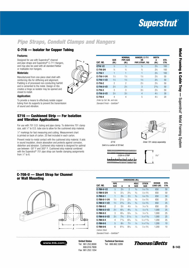
United States
Tel: 901.252.8000800.816.7809
Fax: 901.252.1354
Technical Services
Tel: 888.862.3289www.tnb.com
B-143
Pipe Straps, Conduit Clamps and Hangers
Metal Fram
ing & Cable Tray —
Superstrut® M
etal Framing System
CAT. NO.SIZE
(IN.)
NOMINAL
PIPE SIZE
(IN.)
HANGER, C-711
OR
PIPE STRAP, 702
WIDTH
A
(IN.)
STD.
CTN.
C716 1/2 1⁄2 1⁄2 3⁄4 23⁄8 100
C-716-3/4 3⁄4 3⁄4 3⁄4 23⁄8 100
C-716-1 1 1 1 23⁄8 100
C-716-1-1/4 11⁄4 11⁄4 11⁄4 23⁄8 50
C-716-1-1/2 11⁄2 11⁄2 11⁄2 23⁄8 50
C-716-2 2 2 21⁄2 23⁄8 50
C-716-2-1/2 21⁄2 21⁄2 3 215⁄32 50
C-716-3 3 3 31⁄2 23⁄8 50
C-716-3-1/2 31⁄2 31⁄2 4 41⁄4 30
C-716-4 4 4 5 41⁄4 20
Order by Cat. No. and size.
Standard Finish – GoldGalv ®
AA
Features:
Designed for use with Superstrut® channel and pipe straps and Superstrut® C-711 Hangers, and may also be used with all standard flatbar or malleable iron hangers.
Materials:
Manufactured from one-piece steel shell with reinforcing ribs for stiffening and alignment. Padding is of processed non-conducting hairfelt and is cemented to the metal. Design of ribs creates a hinge so isolator may be opened and closed to install.
Application:
To provide a means to effectively isolate copper tubing from its supports to prevent the transmission of sound and vibration.
Order 701 clamp separately.S716Sold in a carton of 20 feet.
15⁄8"
For use with 701 O.D. tubing and pipe clamp. To determine 701 clamp size, add 1⁄4" to O.D. tube size to allow for the cushioned strip material.
1⁄4" markings for fast measuring and cutting. Measurement chart is printed on back of carton. 20 feet included in each carton.
Prevent metal-to-metal contact with the cushioned strip material. It aids in sound insulation, shock absorption and protects against corrosion, distortion and abrasion. Cushioned strip material is designed for optimal use between -30° F and 300° F. Cushioned strip material combined with the Superstrut® 701 pipe strap can handle clamping assignments from 1⁄4" to 6. CUSH-A-STRIP
A
B
CAT. NO.
DIMENSIONS (IN.)
DESIGN
LOAD LBS.
STD.
CTN.PIPE
SIZE A B
HOLE
SIZE
STOCK
SIZE
C-708-U-1/2 1⁄2 27⁄8 2 9⁄321⁄8 x 15⁄8 650 50
C-708-U-3/4 3⁄4 31⁄16 23⁄169⁄32
1⁄8 x 15⁄8 650 50
C-708-U-1 1 33⁄8 21⁄2 9⁄321⁄8 x 15⁄8 650 50
C-708-U-1-1/4 11⁄4 311⁄16 23⁄169⁄32
1⁄8 x 15⁄8 650 25
C-708-U-1-1/2 11⁄2 315⁄16 31⁄169⁄32
1⁄8 x 15⁄8 650 25
C-708-U-2 2 53⁄4 41⁄8 7⁄161⁄4 x 15⁄8 650 25
C-708-U-2-1/2 21⁄2 63⁄16 49⁄167⁄16
1⁄4 x 15⁄8 1,000 25
C-708-U-3 3 63⁄16 53⁄167⁄16
1⁄4 x 15⁄8 1,000 25
C-708-U-3-1/2 31⁄2 75⁄16 511⁄167⁄16
1⁄4 x 115⁄32 1,000 25
C-708-U-4 4 713⁄16 63⁄167⁄16
1⁄4 x 115⁄32 1,200 25
C-708-U-5 5 87⁄8 71⁄4 7⁄161⁄4 x 115⁄32 1,200 10
C-708-U-6 6 915⁄16 85⁄167⁄16
1⁄4 x 15⁄8 1,200 10
Carbon Steel.
Standard Finish – GoldGalv ®
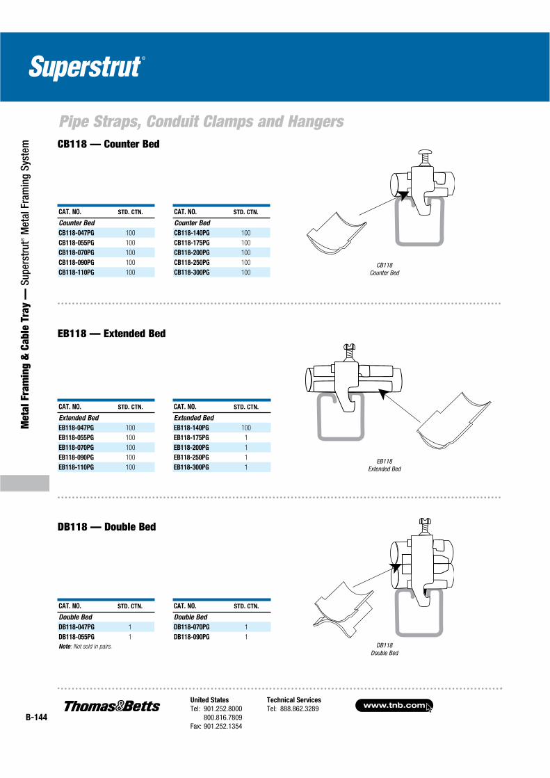
www.tnb.comUnited States
Tel: 901.252.8000800.816.7809
Fax: 901.252.1354
Technical Services
Tel: 888.862.3289B-144
Pipe Straps, Conduit Clamps and Hangers
Met
al F
ram
ing
& C
able
Tra
y —
Sup
erst
rut®
Met
al F
ram
ing
Syst
em
CB118Counter Bed
EB118Extended Bed
DB118Double Bed
CB118 — Counter Bed
EB118 — Extended Bed
DB118 — Double Bed
CAT. NO. STD. CTN. CAT. NO. STD. CTN.
Counter Bed Counter Bed
CB118-047PG 100 CB118-140PG 100
CB118-055PG 100 CB118-175PG 100
CB118-070PG 100 CB118-200PG 100
CB118-090PG 100 CB118-250PG 100
CB118-110PG 100 CB118-300PG 100
CAT. NO. STD. CTN. CAT. NO. STD. CTN.
Extended Bed Extended Bed
EB118-047PG 100 EB118-140PG 100
EB118-055PG 100 EB118-175PG 1
EB118-070PG 100 EB118-200PG 1
EB118-090PG 100 EB118-250PG 1
EB118-110PG 100 EB118-300PG 1
CAT. NO. STD. CTN. CAT. NO. STD. CTN.
Double Bed Double Bed
DB118-047PG 1 DB118-070PG 1
DB118-055PG 1 DB118-090PG 1
Note: Not sold in pairs.

United States
Tel: 901.252.8000800.816.7809
Fax: 901.252.1354
Technical Services
Tel: 888.862.3289www.tnb.com
B-145
Pipe Straps, Conduit Clamps and Hangers
Metal Fram
ing & Cable Tray —
Superstrut® M
etal Framing System
HoleSize
A
C-755 — TPE Cable Clamps
Hole Size
C-755
A
C-755 — Porcelain Cable Clamps
CAT. NO. HOLE SIZE (IN.)
A
(IN.)
STD.
CTN.
C-755-1A 3⁄8 19⁄16 10
C-755-1B 1⁄2 19⁄16 10
C-755-1C 5⁄8 19⁄16 10
C-755-2 3⁄4 25⁄32 10
C-755-2A 7⁄8 25⁄32 10
C-755-2B 1 25⁄32 10
C-755-2C 11⁄8 25⁄32 10
C-755-3 11⁄4 25⁄8 10
C-755-3A 13⁄8 25⁄8 10
C-755-3B 11⁄2 25⁄8 10
C-755-3C 15⁄8 25⁄8 10
C-755-4 13⁄4 35⁄8 10
C-755-4A 17⁄8 35⁄8 10
C-755-4B 2 35⁄8 10
C-755-4C 21⁄8 35⁄8 10
C-755-5 21⁄4 41⁄4 10
C-755-5A 23⁄8 41⁄4 10
C-755-5B 21⁄2 41⁄4 10
C-755-5C 25⁄8 41⁄4 10
C-755-6 25⁄8 45⁄8 10
C-755-6A 27⁄8 45⁄8 10
C-755-6B 3 45⁄8 10
C-755-6C 31⁄8 45⁄8 10
C-755-7 31⁄4 513⁄16 10
C-755-7A 33⁄8 513⁄16 10
C-755-7B 31⁄2 513⁄16 10
C-755-7C 35⁄8 513⁄16 10
C-755-8 35⁄8 67⁄8 5
C-755-8A 37⁄8 67⁄8 5
C-755-8B 4 67⁄8 5
C-755-8C 41⁄8 67⁄8 5
C-755-8D 41⁄4 67⁄8 5
C-755-8E 43⁄8 67⁄8 5
C-755-8F 41⁄2 67⁄8 5
Finish – GoldGalv ® brand with bronze hardware.
Also fits 11⁄2" wide channel.
CAT. NO.HOLE SIZE
(IN.)
A
(IN.) CAT. NO.HOLE SIZE
(IN.)
A
(IN.)
C755 1ATP 3⁄8 1.36 C-755-5B-TP 21⁄2 3.36
C-755-1B-TP 1⁄2 1.36 C-755-5C-TP 25⁄8 3.36
C-755-1C-TP 5⁄8 1.36 C-755-6-TP 23⁄4 3.86
C-755-2-TP 3⁄4 1.86 C-755-6A-TP 27⁄8 3.86
C-755-2A-TP 7⁄8 1.86 C-755-6B-TP 3 3.86
C-755-2B-TP 1 1.86 C-755-6C-TP 31⁄8 3.86
C-755-2C-TP 11⁄8 1.86 C-755-7-TP 31⁄4 4.36
C-755-3-TP 11⁄4 2.36 C-755-7A-TP 33⁄8 4.36
C-755-3A-TP 13⁄8 2.36 C-755-7B-TP 31⁄2 4.36
C-755-3B-TP 11⁄2 2.36 C-755-7C-TP 35⁄8 4.36
C-755-3C-TP 15⁄8 2.36 C-755-8-TP 33⁄4 4.86
C-755-4-TP 13⁄4 2.86 C-755-8A-TP 37⁄8 4.86
C-755-4A-TP 17⁄8 2.86 C-755-8B-TP 4 4.86
C-755-4B-TP 2 2.86 C-755-8C-TP 41⁄8 4.86
C-755-4C-TP 21⁄8 2.86 C-755-8D-TP 41⁄4 5.24
C-755-5-TP 21⁄4 3.36 C-755-8E-TP 43⁄8 5.24
C-755-5A-TP 23⁄8 3.36 C-755-8F-TP 41⁄2 5.24
Non-breakable TPE material
Exceptional chemical resistance
Dielectric strength of 640 volts per mil
Stainless Steel Clamps Type 304 or 316
Electro-Galvanized Steel Clamps with Everdur Nut and Bolt
Flame-retardant TPE insulator
Excellent UV resistance
An easy-to-use one-piece insulator made from Sarlink 4339D, a flame-retardant, high hardness grade TPE polymer that is UL Listed. The tapered flange of the insulator ensures complete isolation and protection of the cable. Options include a Stainless Steel Clamp and hardware or an Electro-Galvanized Clamp with Everdur nut and bolt.
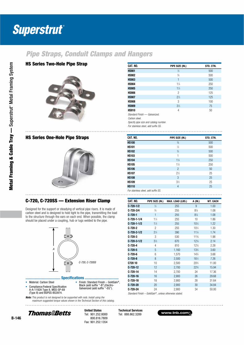
www.tnb.comUnited States
Tel: 901.252.8000800.816.7809
Fax: 901.252.1354
Technical Services
Tel: 888.862.3289B-146
Pipe Straps, Conduit Clamps and Hangers
Met
al F
ram
ing
& C
able
Tra
y —
Sup
erst
rut®
Met
al F
ram
ing
Syst
em
CAT. NO. PIPE SIZE (IN.) STD. CTN.
HS100 3⁄8 500
HS101 1⁄2 500
HS102 3⁄4 500
HS103 1 500
HS104 11⁄4 250
HS105 11⁄2 250
HS106 2 50
HS107 21⁄2 25
HS108 3 25
HS109 31⁄2 25
HS110 4 25
For stainless steel, add suffix SS.
CAT. NO. PIPE SIZE (IN.) STD. CTN.
HS901 1⁄2 500
HS902 3⁄4 500
HS903 1 500
HS904 11⁄4 250
HS905 11⁄2 250
HS906 2 125
HS907 21⁄2 125
HS908 3 100
HS909 31⁄2 75
HS910 4 50
Standard Finish — Galvanized.
Carbon steel.
Specify pipe size and catalog number.
For stainless steel, add suffix SS.
HS Series Two-Hole Pipe Strap
HS Series One-Hole Pipe Straps
Designed for the support or steadying of vertical pipe risers. It is made of carbon steel and is designed to hold tight to the pipe, transmitting the load to the structure through the ears on each end. When possible, the clamp should be placed under a coupling, hub or lugs welded to the pipe.
C-720, C-720SS — Extension Riser Clamp
C-720, C-720SS
A
CAT. NO. PIPE SIZE (IN.) MAX. LOAD (LBS.) A (IN.) WT. EACH
C-720-1/2 1⁄2 255 9 1.00
C-720-3/4 3⁄4 255 87⁄8 1.08
C-720-1 1 255 87⁄8 1.08
C-720-1-1/4 11⁄4 255 10 1.86
C-720-1-1/2 11⁄2 255 101⁄4 1.22
C-720-2 2 255 101⁄4 1.30
C-720-2-1/2 21⁄2 390 111⁄4 1.74
C-720-3 3 530 113⁄8 1.98
C-720-3-1/2 31⁄2 670 127⁄8 2.14
C-720-4 4 810 127⁄8 2.28
C-720-5 5 1,160 133⁄4 3.60
C-720-6 6 1,570 143⁄4 3.68
C-720-8 8 2,500 181⁄2 7.26
C720 10 10 2,500 203⁄4 11.00
C-720-12 12 2,700 223⁄4 15.94
C-720-14 14 2,700 24 17.36
C-720-16 16 2,900 26 29.68
C-720-18 18 2,900 28 31.64
C-720-20 20 2,900 30 34.84
C-720-24 24 2,900 34 50.00
Standard Finish – GoldGalv®, unless otherwise stated.
Material: Carbon Steel
Compliance:Federal Specification A-A-1192A Type 8, MSS-SP-69(Type 8) and BSPSS-BS3974.
Finish: Standard Finish – GoldGalv®,Black (add suffix “-B”),Electro-Galvanized (add suffix “-EG”).
.................................... Specifications ...................................
Note: This product is not designed to be supported with rods. Install using the
maximum suggested torque values shown in the Technical Section of this catalog.
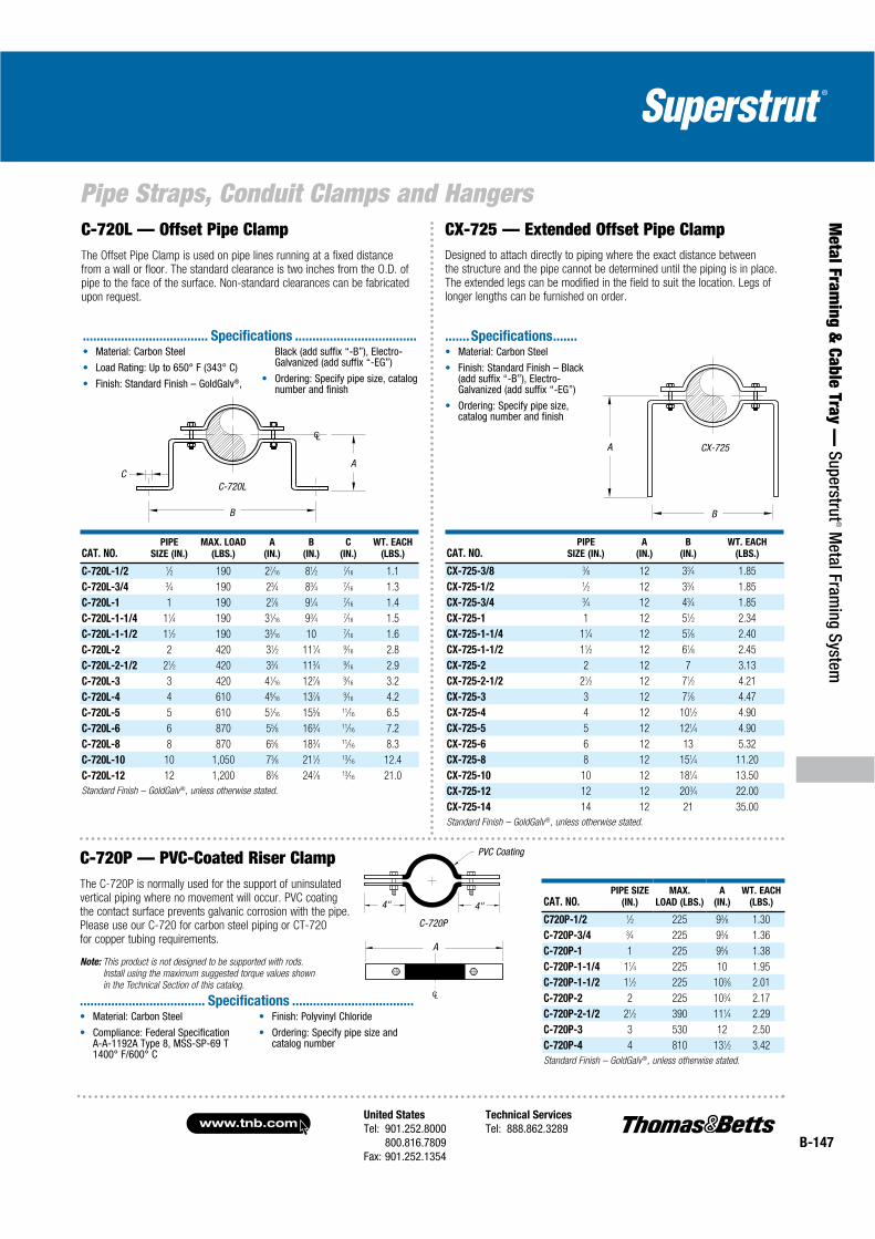
United States
Tel: 901.252.8000800.816.7809
Fax: 901.252.1354
Technical Services
Tel: 888.862.3289www.tnb.com
B-147
Pipe Straps, Conduit Clamps and Hangers
Metal Fram
ing & Cable Tray —
Superstrut® M
etal Framing System
A
B
C-720L — Offset Pipe ClampThe Offset Pipe Clamp is used on pipe lines running at a fixed distance from a wall or floor. The standard clearance is two inches from the O.D. of pipe to the face of the surface. Non-standard clearances can be fabricated upon request.
CAT. NO.PIPE
SIZE (IN.)
MAX. LOAD
(LBS.)
A
(IN.)
B
(IN.)
C
(IN.)
WT. EACH
(LBS.)
C-720L-1/2 1⁄2 190 27⁄16 81⁄2 7⁄16 1.1
C-720L-3/4 3⁄4 190 23⁄4 83⁄4 7⁄16 1.3
C-720L-1 1 190 27⁄8 91⁄4 7⁄16 1.4
C-720L-1-1/4 11⁄4 190 31⁄16 93⁄4 7⁄16 1.5
C-720L-1-1/2 11⁄2 190 33⁄16 10 7⁄16 1.6
C-720L-2 2 420 31⁄2 111⁄4 9⁄16 2.8
C-720L-2-1/2 21⁄2 420 33⁄4 113⁄4 9⁄16 2.9
C-720L-3 3 420 41⁄16 127⁄8 9⁄16 3.2
C-720L-4 4 610 49⁄16 137⁄8 9⁄16 4.2
C-720L-5 5 610 51⁄16 155⁄8 11⁄16 6.5
C-720L-6 6 870 55⁄8 163⁄4 11⁄16 7.2
C-720L-8 8 870 65⁄8 183⁄4 11⁄16 8.3
C-720L-10 10 1,050 73⁄8 211⁄2 13⁄16 12.4
C-720L-12 12 1,200 83⁄8 247⁄8 13⁄16 21.0
Standard Finish – GoldGalv®, unless otherwise stated.
C-720L
A
B
C
CAT. NO.PIPE
SIZE (IN.)
A
(IN.)
B
(IN.)
WT. EACH
(LBS.)
CX-725-3/8 3⁄8 12 33⁄4 1.85
CX-725-1/2 1⁄2 12 33⁄4 1.85
CX-725-3/4 3⁄4 12 43⁄4 1.85
CX-725-1 1 12 51⁄2 2.34
CX-725-1-1/4 11⁄4 12 57⁄8 2.40
CX-725-1-1/2 11⁄2 12 61⁄8 2.45
CX-725-2 2 12 7 3.13
CX-725-2-1/2 21⁄2 12 71⁄2 4.21
CX-725-3 3 12 77⁄8 4.47
CX-725-4 4 12 101⁄2 4.90
CX-725-5 5 12 121⁄4 4.90
CX-725-6 6 12 13 5.32
CX-725-8 8 12 151⁄4 11.20
CX-725-10 10 12 181⁄4 13.50
CX-725-12 12 12 203⁄4 22.00
CX-725-14 14 12 21 35.00
Standard Finish – GoldGalv®, unless otherwise stated.
CX-725
CX-725 — Extended Offset Pipe Clamp
C-720P — PVC-Coated Riser ClampThe C-720P is normally used for the support of uninsulated vertical piping where no movement will occur. PVC coating the contact surface prevents galvanic corrosion with the pipe. Please use our C-720 for carbon steel piping or CT-720 for copper tubing requirements.
Note: This product is not designed to be supported with rods.
Install using the maximum suggested torque values shown
in the Technical Section of this catalog.
CAT. NO.PIPE SIZE
(IN.)
MAX.
LOAD (LBS.)
A
(IN.)
WT. EACH
(LBS.)
C720P-1/2 1⁄2 225 93⁄8 1.30
C-720P-3/4 3⁄4 225 93⁄8 1.36
C-720P-1 1 225 95⁄8 1.38
C-720P-1-1/4 11⁄4 225 10 1.95
C-720P-1-1/2 11⁄2 225 103⁄8 2.01
C-720P-2 2 225 103⁄4 2.17
C-720P-2-1/2 21⁄2 390 111⁄4 2.29
C-720P-3 3 530 12 2.50
C-720P-4 4 810 131⁄2 3.42
Standard Finish – GoldGalv®, unless otherwise stated.
C-720P
PVC Coating
4"4"
A
Material: Carbon Steel
Load Rating: Up to 650° F (343° C)
Finish: Standard Finish – GoldGalv®,
Black (add suffix “-B”), Electro-Galvanized (add suffix “-EG”)
Ordering: Specify pipe size, catalog number and finish
.................................... Specifications ...................................Material: Carbon Steel
Finish: Standard Finish – Black(add suffix “-B”), Electro-Galvanized (add suffix “-EG”)
Ordering: Specify pipe size,catalog number and finish
.......Specifications.......
Material: Carbon Steel
Compliance: Federal Specification A-A-1192A Type 8, MSS-SP-69 T 1400° F/600° C
Finish: Polyvinyl Chloride
Ordering: Specify pipe size and catalog number
.................................... Specifications ...................................
Designed to attach directly to piping where the exact distance between the structure and the pipe cannot be determined until the piping is in place. The extended legs can be modified in the field to suit the location. Legs of longer lengths can be furnished on order.
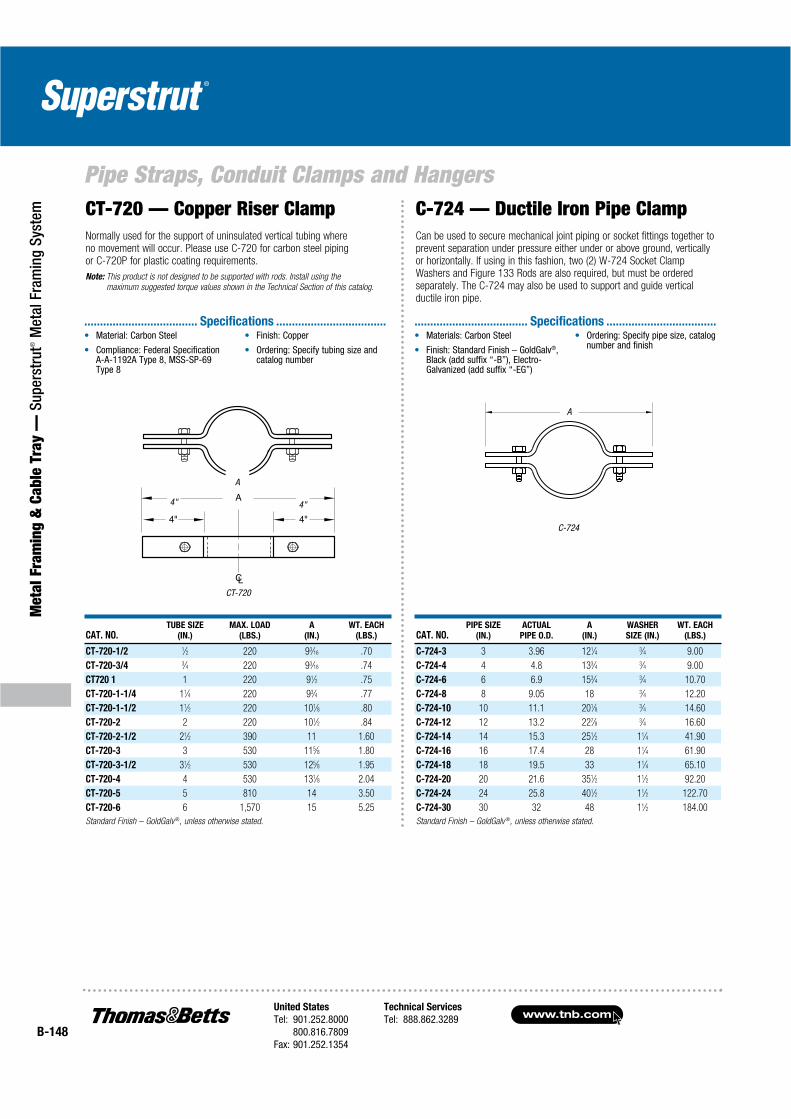
www.tnb.comUnited States
Tel: 901.252.8000800.816.7809
Fax: 901.252.1354
Technical Services
Tel: 888.862.3289B-148
Pipe Straps, Conduit Clamps and Hangers
Met
al F
ram
ing
& C
able
Tra
y —
Sup
erst
rut®
Met
al F
ram
ing
Syst
em
CT-720
CT-720 — Copper Riser ClampNormally used for the support of uninsulated vertical tubing where no movement will occur. Please use C-720 for carbon steel piping or C-720P for plastic coating requirements.
Note: This product is not designed to be supported with rods. Install using the
maximum suggested torque values shown in the Technical Section of this catalog.
C-724 — Ductile Iron Pipe ClampCan be used to secure mechanical joint piping or socket fittings together to prevent separation under pressure either under or above ground, vertically or horizontally. If using in this fashion, two (2) W-724 Socket Clamp Washers and Figure 133 Rods are also required, but must be ordered separately. The C-724 may also be used to support and guide vertical ductile iron pipe.
C-724
A
4" 4"
A
CAT. NO.TUBE SIZE
(IN.)
MAX. LOAD
(LBS.)
A
(IN.)
WT. EACH
(LBS.)
CT-720-1/2 1⁄2 220 93⁄16 .70
CT-720-3/4 3⁄4 220 93⁄16 .74
CT720 1 1 220 91⁄2 .75
CT-720-1-1/4 11⁄4 220 93⁄4 .77
CT-720-1-1/2 11⁄2 220 101⁄8 .80
CT-720-2 2 220 101⁄2 .84
CT-720-2-1/2 21⁄2 390 11 1.60
CT-720-3 3 530 115⁄8 1.80
CT-720-3-1/2 31⁄2 530 125⁄8 1.95
CT-720-4 4 530 131⁄8 2.04
CT-720-5 5 810 14 3.50
CT-720-6 6 1,570 15 5.25
Standard Finish – GoldGalv ®, unless otherwise stated.
CAT. NO.PIPE SIZE
(IN.)
ACTUAL
PIPE O.D.
A
(IN.)
WASHER
SIZE (IN.)
WT. EACH
(LBS.)
C-724-3 3 3.96 121⁄4 3⁄4 9.00
C-724-4 4 4.8 133⁄4 3⁄4 9.00
C-724-6 6 6.9 153⁄4 3⁄4 10.70
C-724-8 8 9.05 18 3⁄4 12.20
C-724-10 10 11.1 201⁄8 3⁄4 14.60
C-724-12 12 13.2 227⁄8 3⁄4 16.60
C-724-14 14 15.3 251⁄2 11⁄4 41.90
C-724-16 16 17.4 28 11⁄4 61.90
C-724-18 18 19.5 33 11⁄4 65.10
C-724-20 20 21.6 351⁄2 11⁄2 92.20
C-724-24 24 25.8 401⁄2 11⁄2 122.70
C-724-30 30 32 48 11⁄2 184.00
Standard Finish – GoldGalv ®, unless otherwise stated.
Materials: Carbon Steel
Finish: Standard Finish – GoldGalv®,Black (add suffix “-B”), Electro-Galvanized (add suffix “-EG”)
Ordering: Specify pipe size, catalog number and finish
.................................... Specifications ...................................Material: Carbon Steel
Compliance: Federal Specification A-A-1192A Type 8, MSS-SP-69 Type 8
Finish: Copper
Ordering: Specify tubing size andcatalog number
.................................... Specifications ...................................

United States
Tel: 901.252.8000800.816.7809
Fax: 901.252.1354
Technical Services
Tel: 888.862.3289www.tnb.com
B-149
Pipe Straps, Conduit Clamps and Hangers
Metal Fram
ing & Cable Tray —
Superstrut® M
etal Framing System
CAT. NO. PIPE SIZE (IN.)
MAXIMUM LOAD
C (IN.)
ROD TAKE OUT
D (IN.) E (IN.) F (IN.)
WT. EACH
(LBS.)650° F/343° C 750° F/343° C
C725 1/2 1⁄2 500 445 3⁄8 11⁄8 15⁄8 3⁄8 .31
C-725-3/4 3⁄4 500 445 3⁄8 11⁄4 13⁄4 3⁄8 .35
C-725-1 1 500 445 3⁄8 13⁄8 17⁄8 3⁄8 .39
C-725-1-1/4 11⁄4 500 445 3⁄8 15⁄8 21⁄8 3⁄8 .40
C-725-1-1/2 11⁄2 800 715 3⁄8 13⁄4 21⁄4 3⁄8 .45
C-725-2 2 1,040 930 1⁄2 21⁄8 25⁄8 1⁄2 1.23
C-725-2-1/2 21⁄2 1,040 930 5⁄8 25⁄8 31⁄8 1⁄2 1.33
C-725-3 3 1,040 930 5⁄8 3 31⁄2 1⁄2 1.53
C-725-4 4 1,040 930 3⁄4 35⁄8 43⁄8 1⁄2 2.20
C-725-5 5 1,040 930 3⁄4 41⁄4 5 1⁄2 2.39
C-725-6 6 1,615 1,440 7⁄8 51⁄4 61⁄4 3⁄4 5.87
C-725-8 8 1,615 1,440 1 63⁄8 73⁄8 3⁄4 6.95
C-725-10 10 2,490 2,220 1 75⁄8 83⁄4 7⁄8 14.39
C-725-12 12 2,490 2,220 11⁄8 83⁄4 101⁄4 7⁄8 16.73
C-725-14 14 2,490 2,220 11⁄8 91⁄4 105⁄8 7⁄8 21.26
C-725-16 16 2,490 2,220 11⁄8 101⁄4 115⁄8 7⁄8 23.39
C-725-18 18 3,060 2,730 11⁄4 115⁄8 13 1 32.96
C-725-20 20 3,060 2,730 13⁄8 123⁄4 141⁄8 11⁄8 36.74
C-725-24 24 3,060 2,730 11⁄2 151⁄4 167⁄8 11⁄8 52.96
C-725-30 30 3,500 3,360 2 181⁄2 203⁄4 11⁄2 103.50
Standard Finish – GoldGalv ®, unless otherwise stated.
C-725 — Two-Bolt Pipe ClampDesigned to suspend cold or hot pipe lines where little or no insulation is required. The C-725 is usually used with an E-120-A Weldless Eyenut or E-157 Welded Eyerod. See Figure 298 heavy-duty Two-Bolt Clamp when higher loads are required. We will also design to meet special requirements such as special pipe sizes.
Rated Loads are for up to 750° F (399° C).
C-726
F C
D
D
E
E
C
Material: Carbon Steel
Compliance: Federal Specification A-A-1192A Type 4, MSS-SP-69 Type 4 and BSPSS-BS3974
Finish: Standard Finish – GoldGalv®,Black (add suffix “-B”), Electro-Galvanized (add suffix “-EG”)
Ordering: Specify catalog number, finish and pipe size. Also, include any special requirements for C-725
.................................... Specifications ...................................

www.tnb.comUnited States
Tel: 901.252.8000800.816.7809
Fax: 901.252.1354
Technical Services
Tel: 888.862.3289B-150
Pipe Straps, Conduit Clamps and Hangers
Met
al F
ram
ing
& C
able
Tra
y —
Sup
erst
rut®
Met
al F
ram
ing
Syst
em
CAT. NO. PIPE SIZE (IN.)
MAXIMUM LOAD
B (IN.) C (IN.) D (IN.)
TAKE OUT E
(IN.) F (IN.) H (IN.)
WT. EACH
(LBS.)650° F/343° C 750° F/399° C
C-726-1/2 1⁄2 950 845 1 5⁄8 27⁄8 21⁄4 3⁄8 15⁄8 .61
C-726-3/4 3⁄4 950 845 11⁄8 5⁄8 31⁄4 21⁄2 3⁄8 13⁄4 .66
C-726-1 1 950 845 11⁄2 5⁄8 33⁄4 21⁄2 3⁄8 21⁄4 .69
C-726-1/4 11⁄4 950 845 11⁄2 3⁄4 35⁄8 27⁄8 3⁄8 21⁄4 .75
C-726-1-3/4 13⁄4 1,545 1,380 13⁄4 1 47⁄8 41⁄4 5⁄8 21⁄2 2.14
C-726-2 2 1,545 1,380 21⁄4 11⁄4 57⁄8 51⁄4 5⁄8 23⁄4 2.43
C-726-2-3/4 23⁄4 1,545 1,380 21⁄4 11⁄4 61⁄4 53⁄8 5⁄8 3 2.92
C-726-3 3 1,545 1,380 23⁄4 11⁄4 65⁄8 6 5⁄8 31⁄2 3.19
C-726-4 4 2,500 2,230 33⁄8 1 75⁄8 61⁄2 3⁄4 41⁄2 7.12
C-726-5 5 2,500 2,230 4 11⁄4 81⁄4 7 3⁄4 51⁄4 7.96
C-726-6 6 2,865 2,555 43⁄4 11⁄4 95⁄8 81⁄4 7⁄8 61⁄4 11.85
C-726-8 8 2,865 2,555 53⁄4 11⁄4 105⁄8 91⁄4 7⁄8 71⁄4 13.59
C-726-10 10 3,240 2,890 67⁄8 11⁄4 12 101⁄2 1 81⁄4 21.33
C-726-12 12 3,240 2,890 83⁄8 11⁄2 13 111⁄2 1 97⁄8 23.65
C-726-14 14 4,300 3,835 91⁄4 2 143⁄8 123⁄4 11⁄4 103⁄4 38.78
C-726-16 16 4,300 3,835 10 2 155⁄8 14 11⁄4 113⁄4 42.89
C-726-18 18 4,300 3,835 115⁄8 2 163⁄4 151⁄4 11⁄4 131⁄4 46.35
C-726-20 20 4,500 4,015 123⁄8 2 171⁄2 157⁄8 13⁄8 14 58.67
C-726-24 24 5,490 4,900 143⁄4 2 197⁄8 177⁄8 11⁄2 163⁄8 89.32
C-726-30 30 7,500 6,690 181⁄2 11⁄2 263⁄8 233⁄8 11⁄2 21 140.89
C-726-36 36 1,0500 9,360 221⁄2 3 321⁄4 283⁄4 13⁄4 26 246.44
Standard Finish – GoldGalv ® unless otherwise stated.
C-726 — Three-Bolt Pipe ClampDesigned for hot-insulated pipe lines up to 750° F. The spacer on the top inner bolt provides uniform space for the connecting eyerod or weldless eyenut. We will also design to meet special requirements such as special pipe sizes.
Rated Loads are for up to 750° F (399° C).
C-726
FC
E
B
D
H
®
.................................... Specifications ...................................

United States
Tel: 901.252.8000800.816.7809
Fax: 901.252.1354
Technical Services
Tel: 888.862.3289www.tnb.com
B-151
Pipe Straps, Conduit Clamps and Hangers
Metal Fram
ing & Cable Tray —
Superstrut® M
etal Framing System
CAT. NO.PIPE SIZE
(IN.)
MAXIMUM LOAD B
(IN.)
C
(IN.)
D
(IN.)
TAKE OUT E
(IN.)
F
(IN.)
H
(IN.) (LBS.)950° F/510° C 1000° F/538° C 1050° F/566° C
A-726-3/4 3⁄4 870 600 440 11⁄8 5⁄8 3 21⁄2 3⁄8 15⁄8 1.09
A-726-1 1 870 600 440 11⁄4 5⁄8 31⁄8 25⁄8 3⁄8 13⁄4 1.14
A-726-1-1/4 11⁄4 870 600 440 11⁄2 3⁄4 33⁄4 27⁄8 3⁄8 21⁄4 1.23
A-726-1-1/2 11⁄2 1,400 1,000 700 13⁄4 1 47⁄8 41⁄8 5⁄8 23⁄8 2.48
A-726-2 2 1,400 1,000 700 21⁄8 1 57⁄8 51⁄8 5⁄8 23⁄4 2.70
A-726-2-1/2 21⁄2 1,400 1,000 700 21⁄4 1 61⁄8 53⁄8 5⁄8 3 2.76
A-726-3 3 1,400 1,000 700 23⁄4 1 63⁄4 6 5⁄8 31⁄2 3.19
A-726-4 4 2,300 1,600 1,100 33⁄8 1 75⁄8 61⁄2 3⁄4 41⁄2 7.30
A-726-5 5 2,300 1,600 1,100 4 11⁄8 81⁄8 7 3⁄4 51⁄8 7.96
A-726-6 6 2,600 1,800 1,300 43⁄4 11⁄4 10 85⁄8 7⁄8 61⁄8 12.26
A-726-8 8 2,600 1,800 1,300 53⁄4 11⁄4 11 95⁄8 7⁄8 71⁄8 14.04
A-726-10 10 3,000 2,100 1,500 67⁄8 11⁄4 12 101⁄2 1 81⁄4 21.33
A-726-12 12 3,000 2,100 1,500 83⁄8 11⁄2 131⁄8 115⁄8 1 97⁄8 24.00
A-726-14 14 3,900 2,800 2,000 91⁄8 2 141⁄8 123⁄4 11⁄4 103⁄4 38.78
A-726-16 16 3,900 2,800 2,000 10 2 151⁄8 14 11⁄4 113⁄4 43.13
A-726-18 18 39 2,800 2,000 115⁄8 2 163⁄4 151⁄8 11⁄4 131⁄4 47.78
A-726-20 20 5,000 3,200 2,000 123⁄8 2 171⁄2 157⁄8 11⁄8 14 58.67
A-726-24 24 5,500 3,500 2,700 143⁄4 11⁄2 197⁄8 177⁄8 11⁄2 163⁄8 90.82
Standard Finish – GoldGalv®, unless otherwise stated.
Pipe Clamps — A-726, Alloy Three-Bolt Pipe Clamp
A-726
CF
E
B
D
H
Designed for hot-insulated pipelines. The spacer on the top inner bolt provides uniform space for the connecting eyerod or weldless eyenut.
Temperature range: above 750° F (399° C) to 1050° F (566° C).
CAT. NO.PIPE
SIZE (IN.)
MAX.
LOAD (LBS.)
A
(IN.)
B
(IN.)
C
(IN.)
ROD TAKE
OUT E (IN.)
WT. EACH
(LBS.)
C-710-1/2 1⁄2 610 3⁄8 23⁄4 31⁄8 17⁄8 .27
C-710-3/4 3⁄4 610 3⁄8 21⁄8 23⁄4 11⁄2 .29
C-710-1 1 610 3⁄8 3 33⁄4 21⁄4 .33
C-710-1-1/4 11⁄4 610 3⁄8 31⁄8 4 21⁄4 .36
C-710-1-1/2 11⁄2 610 3⁄8 31⁄4 41⁄4 23⁄8 .42
C-710-2 2 610 3⁄8 33⁄8 45⁄8 31⁄8 .52
C-710-2-1/2 21⁄2 1,130 1⁄2 41⁄8 55⁄8 31⁄8 .61
C-710-3 3 1,130 1⁄2 5 63⁄4 41⁄8 .90
C-710-3-1/2 31⁄2 1,130 1⁄2 41⁄2 65⁄8 35⁄8 .99
C-710-4 4 1,430 5⁄8 53⁄8 73⁄4 43⁄8 1.40
C-710-5 5 1,430 5⁄8 6 87⁄8 5 2.10
C-710-6 6 1,940 3⁄4 7 101⁄2 57⁄8 3.00
Standard Finish – GoldGalv®, unless otherwise stated.
Pipe Hangers — C-710, C-710F, C-710P, C-710SSDesigned to support non-insulated, stationary lines from above, allowing for approximately 1" to 11⁄2"of vertical adjustment after the pipe is in place. The lower nut (not furnished) adjusts the pipe line to the proper elevation, the top nut (not furnished) prevents loosening due to vibration and must be tightened securely to assure proper hanger performance.
Rated Loads are for up to 650° F (343° C) for carbon steel. Maximum PVC temperature is 140° F (60° C).
CAT. NO.PIPE
SIZE (IN.)
MAX.
LOAD (LBS.)
A
(IN.)
B
(IN.)
C
(IN.)
ROD TAKE
OUT E (IN.)
WT. EACH
(LBS.)
C-710-7 7 2,000 3⁄4 75⁄8 113⁄4 61⁄2 5.42
C-710-8 8 2,000 3⁄4 81⁄2 123⁄4 63⁄4 5.25
C-710-10 10 3,600 7⁄8 10 153⁄8 81⁄4 9.10
C-710-12 12 3,800 7⁄8 111⁄8 171⁄2 91⁄4 11.75
C-710-14 14 4,200 1 121⁄2 191⁄2 105⁄8 14.25
C-710-16 16 4,800 1 15 23 131⁄8 20.75
C-710-18 18 4,800 11⁄4 153⁄4 243⁄4 133⁄4 23.00
C-710-20 20 4,800 11⁄4 173⁄8 273⁄8 151⁄4 41.50
C-710-24 24 4,800 11⁄4 195⁄8 315⁄8 171⁄2 50.00
C-710-30 30 6,000 11⁄4 243⁄4 403⁄4 213⁄4 68.08
C-710-36 36 9,500 11⁄2 327⁄8 507⁄8 30 68.68
Standard Finish – GoldGalv®, unless otherwise stated.
C-710
A
B
C
E
®
.................................... Specifications ...................................
®
.................................... Specifications ...................................
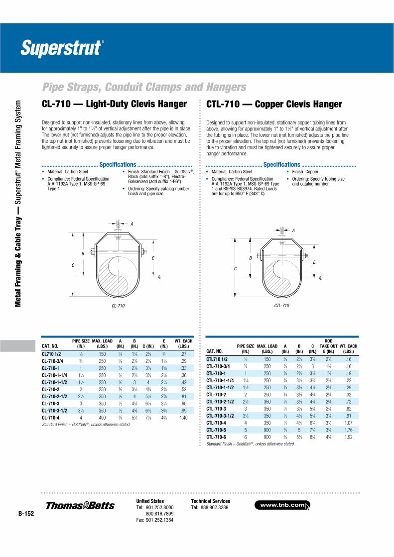
www.tnb.comUnited States
Tel: 901.252.8000800.816.7809
Fax: 901.252.1354
Technical Services
Tel: 888.862.3289B-152
Pipe Straps, Conduit Clamps and Hangers
Met
al F
ram
ing
& C
able
Tra
y —
Sup
erst
rut®
Met
al F
ram
ing
Syst
em
CAT. NO.PIPE SIZE
(IN.)
MAX. LOAD
(LBS.)
A
(IN.)
B
(IN.) C (IN.)
E
(IN.)
WT. EACH
(LBS.)
CL710 1/2 1⁄2 150 3⁄8 17⁄8 23⁄8 3⁄4 .27
CL-710-3/4 3⁄4 250 3⁄8 23⁄8 27⁄8 11⁄2 .29
CL-710-1 1 250 3⁄8 23⁄8 37⁄8 15⁄8 .33
CL-710-1-1/4 11⁄4 250 3⁄8 27⁄8 33⁄4 21⁄8 .36
CL-710-1-1/2 11⁄2 250 3⁄8 3 4 21⁄4 .42
CL-710-2 2 250 3⁄8 31⁄2 43⁄4 23⁄4 .52
CL-710-2-1/2 21⁄2 350 1⁄2 4 51⁄2 27⁄8 .81
CL-710-3 3 350 1⁄2 41⁄4 61⁄8 31⁄4 .90
CL-710-3-1/2 31⁄2 350 1⁄2 43⁄8 61⁄2 33⁄8 .99
CL-710-4 4 400 5⁄8 51⁄2 77⁄8 43⁄8 1.40
Standard Finish – GoldGalv®, unless otherwise stated.
CL-710
A
B
C
E
CL-710 — Light-Duty Clevis Hanger
Designed to support non-insulated, stationary lines from above, allowing for approximately 1" to 11⁄2" of vertical adjustment after the pipe is in place. The lower nut (not furnished) adjusts the pipe line to the proper elevation, the top nut (not furnished) prevents loosening due to vibration and must be tightened securely to assure proper hanger performance.
CAT. NO.PIPE SIZE
(IN.)
MAX. LOAD
(LBS.)
A
(IN.)
B
(IN.)
C
(IN.)
ROD
TAKE OUT
E (IN.)
WT. EACH
(LBS.)
CTL710 1/2 1⁄2 150 3⁄8 27⁄8 31⁄8 21⁄4 .16
CTL-710-3/4 3⁄4 250 3⁄8 25⁄8 3 17⁄8 .16
CTL-710-1 1 250 3⁄8 25⁄8 31⁄8 17⁄8 .19
CTL-710-1-1/4 11⁄4 250 3⁄8 31⁄8 33⁄4 23⁄8 .22
CTL-710-1-1/2 11⁄2 250 3⁄8 33⁄8 41⁄8 25⁄8 .29
CTL-710-2 2 250 3⁄8 33⁄8 43⁄8 25⁄8 .32
CTL-710-2-1/2 21⁄2 350 1⁄2 35⁄8 47⁄8 25⁄8 .72
CTL-710-3 3 350 1⁄2 37⁄8 53⁄8 27⁄8 .82
CTL-710-3-1/2 31⁄2 350 1⁄2 41⁄8 57⁄8 31⁄8 .91
CTL-710-4 4 350 1⁄2 41⁄2 61⁄4 31⁄2 1.07
CTL-710-5 5 900 5⁄8 5 73⁄4 37⁄8 1.76
CTL-710-6 6 900 5⁄8 53⁄4 87⁄8 45⁄8 1.92
Standard Finish – GoldGalv®, unless otherwise stated.
CTL-710
CTL-710 — Copper Clevis Hanger
Designed to support non-insulated, stationary copper tubing lines from above, allowing for approximately 1" to 11⁄2" of vertical adjustment after the tubing is in place. The lower nut (not furnished) adjusts the pipe line to the proper elevation. The top nut (not furnished) prevents loosening due to vibration and must be tightened securely to assure proper hanger performance.
A
B
CE
®
.................................... Specifications ................................... .................................... Specifications ...................................
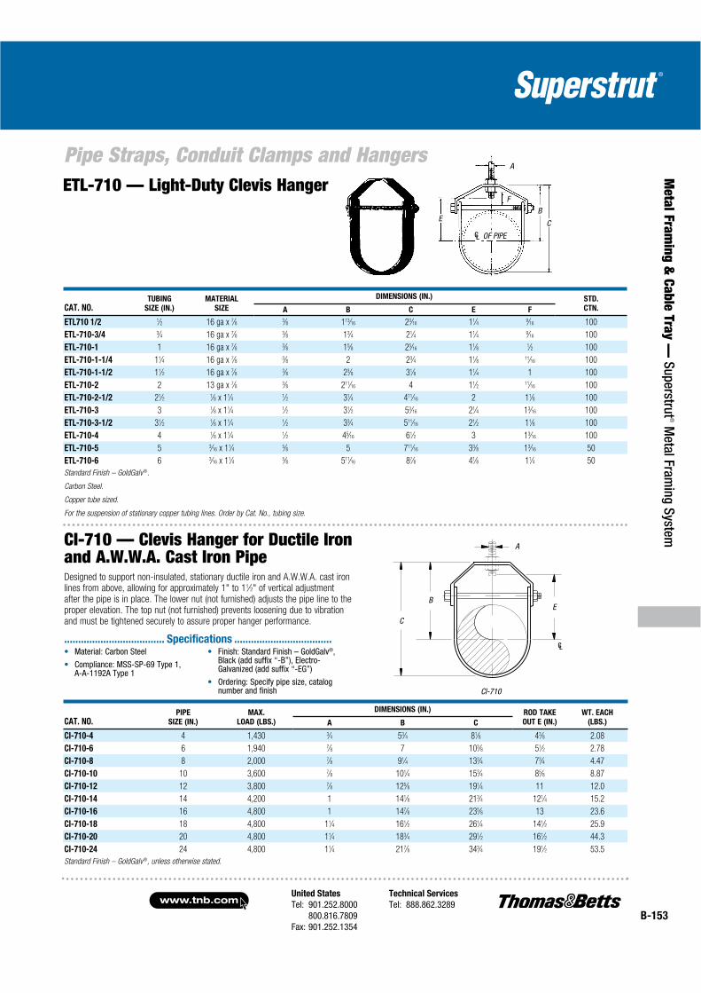
United States
Tel: 901.252.8000800.816.7809
Fax: 901.252.1354
Technical Services
Tel: 888.862.3289www.tnb.com
B-153
Pipe Straps, Conduit Clamps and Hangers
Metal Fram
ing & Cable Tray —
Superstrut® M
etal Framing System
ETL-710 — Light-Duty Clevis Hanger
CAT. NO.TUBING
SIZE (IN.)
MATERIAL
SIZE
DIMENSIONS (IN.) STD.
CTN.A B C E F
ETL710 1/2 1⁄2 16 ga x 7⁄8 3⁄8 113⁄16 23⁄16 11⁄4 9⁄16 100
ETL-710-3/4 3⁄4 16 ga x 7⁄8 3⁄8 13⁄4 21⁄4 11⁄4 9⁄16 100
ETL-710-1 1 16 ga x 7⁄8 3⁄8 15⁄8 25⁄16 11⁄8 1⁄2 100
ETL-710-1-1/4 11⁄4 16 ga x 7⁄8 3⁄8 2 23⁄4 11⁄8 11⁄16 100
ETL-710-1-1/2 11⁄2 16 ga x 7⁄8 3⁄8 23⁄8 31⁄8 11⁄4 1 100
ETL-710-2 2 13 ga x 7⁄8 3⁄8 211⁄16 4 11⁄2 11⁄16 100
ETL-710-2-1/2 21⁄2 1⁄8 x 11⁄4 1⁄2 31⁄4 411⁄16 2 11⁄8 100
ETL-710-3 3 1⁄8 x 11⁄4 1⁄2 31⁄2 53⁄16 21⁄4 13⁄16 100
ETL-710-3-1/2 31⁄2 1⁄8 x 11⁄4 1⁄2 33⁄4 511⁄16 21⁄2 11⁄8 100
ETL-710-4 4 1⁄8 x 11⁄4 1⁄2 45⁄16 61⁄2 3 13⁄16 100
ETL-710-5 5 3⁄16 x 11⁄4 5⁄8 5 711⁄16 33⁄8 13⁄16 50
ETL-710-6 6 3⁄16 x 11⁄4 5⁄8 511⁄16 87⁄8 41⁄8 11⁄4 50
Standard Finish – GoldGalv®.
Carbon Steel.
Copper tube sized.
For the suspension of stationary copper tubing lines. Order by Cat. No., tubing size.
CE
FB
A
OF PIPECL
CAT. NO.PIPE
SIZE (IN.)
MAX.
LOAD (LBS.)
DIMENSIONS (IN.) ROD TAKE
OUT E (IN.)
WT. EACH
(LBS.)A B C
CI-710-4 4 1,430 3⁄4 53⁄4 81⁄8 43⁄8 2.08
CI-710-6 6 1,940 7⁄8 7 103⁄8 51⁄2 2.78
CI-710-8 8 2,000 7⁄8 91⁄4 133⁄4 73⁄4 4.47
CI-710-10 10 3,600 7⁄8 101⁄4 153⁄4 85⁄8 8.87
CI-710-12 12 3,800 7⁄8 125⁄8 191⁄4 11 12.0
CI-710-14 14 4,200 1 141⁄8 213⁄4 121⁄4 15.2
CI-710-16 16 4,800 1 147⁄8 235⁄8 13 23.6
CI-710-18 18 4,800 11⁄4 161⁄2 261⁄4 141⁄2 25.9
CI-710-20 20 4,800 11⁄4 183⁄4 291⁄2 161⁄2 44.3
CI-710-24 24 4,800 11⁄4 217⁄8 343⁄4 191⁄2 53.5
Standard Finish – GoldGalv®, unless otherwise stated.
CI-710
C
B
A
E
CL
CI-710 — Clevis Hanger for Ductile Ironand A.W.W.A. Cast Iron PipeDesigned to support non-insulated, stationary ductile iron and A.W.W.A. cast iron lines from above, allowing for approximately 1" to 11⁄2" of vertical adjustment after the pipe is in place. The lower nut (not furnished) adjusts the pipe line to the proper elevation. The top nut (not furnished) prevents loosening due to vibration and must be tightened securely to assure proper hanger performance.
®
.................................... Specifications ...................................
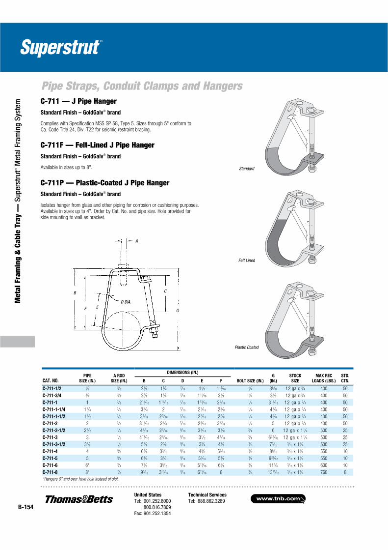
www.tnb.comUnited States
Tel: 901.252.8000800.816.7809
Fax: 901.252.1354
Technical Services
Tel: 888.862.3289B-154
Pipe Straps, Conduit Clamps and Hangers
Met
al F
ram
ing
& C
able
Tra
y —
Sup
erst
rut®
Met
al F
ram
ing
Syst
em
A
G
CB
F E D DIA.
CAT. NO.PIPE
SIZE (IN.)
A ROD
SIZE (IN.)
DIMENSIONS (IN.)
BOLT SIZE (IN.)
G
(IN.)
STOCK
SIZE
MAX REC
LOADS (LBS.)
STD.
CTN.B C D E F
C-711-1/2 1⁄2 3⁄8 25⁄8 13⁄4 7⁄16 11⁄2 115⁄161⁄4 35⁄32 12 ga x 3⁄4 400 50
C-711-3/4 3⁄4 3⁄8 27⁄8 17⁄8 7⁄16 111⁄16 21⁄8 1⁄4 31⁄2 12 ga x 3⁄4 400 50
C-711-1 1 3⁄ 8 2 15⁄ 16 1 15⁄ 167⁄ 16 1 13⁄ 16 2 5⁄ 16
1⁄ 4 3 11⁄ 16 12 ga x 3⁄ 4 400 50
C-711-1-1/4 1 1⁄ 43⁄ 8 3 1⁄ 4 2 7⁄ 16 2 1⁄ 16 2 5⁄ 8
1⁄ 4 4 1⁄ 8 12 ga x 3⁄ 4 400 50
C-711-1-1/2 1 1⁄ 23⁄ 8 3 9⁄ 16 2 3⁄ 16
7⁄ 16 2 7⁄ 16 2 7⁄ 81⁄ 4 4 5⁄ 8 12 ga x 3⁄ 4 400 50
C-711-2 2 3⁄ 8 3 11⁄ 16 2 1⁄ 87⁄ 16 2 9⁄ 16 3 1⁄ 16
1⁄ 4 5 12 ga x 3⁄ 4 400 50
C-711-2-1/2 2 1⁄ 21⁄ 2 4 7⁄ 16 2 7⁄ 16
9⁄ 16 3 3⁄ 16 3 5⁄ 83⁄ 8 6 12 ga x 1 1⁄ 4 500 25
C-711-3 3 1⁄ 2 4 13⁄ 16 2 9⁄ 169⁄ 16 3 1⁄ 2 4 1⁄ 16
3⁄ 8 6 21⁄ 32 12 ga x 1 1⁄ 4 500 25
C-711-3-1/2 31⁄2 1⁄2 51⁄8 25⁄8 9⁄16 33⁄4 43⁄8 3⁄8 75⁄163⁄16 x 11⁄4 500 25
C-711-4 4 5⁄8 61⁄8 33⁄169⁄16 45⁄8 53⁄16
3⁄8 89⁄163⁄16 x 11⁄4 550 10
C-711-5 5 5⁄8 63⁄4 31⁄4 9⁄16 51⁄16 53⁄8 3⁄8 923⁄323⁄16 x 11⁄4 550 10
C-711-6 6* 3⁄4 73⁄4 39⁄169⁄16 513⁄16 65⁄8 3⁄8 111⁄4 3⁄16 x 13⁄4 600 10
C-711-8 8* 7⁄8 93⁄16 315⁄169⁄16 615⁄16 8 3⁄8 1311⁄16
3⁄16 x 13⁄4 760 8
*Hangers 6" and over have hole instead of slot.
Felt Lined
Standard
Plastic Coated
C-711 — J Pipe HangerStandard Finish – GoldGalv® brand
Complies with Specification MSS SP 58, Type 5. Sizes through 5" conform toCa. Code Title 24, Div. T22 for seismic restraint bracing.
C-711F — Felt-Lined J Pipe HangerStandard Finish – GoldGalv® brand
Available in sizes up to 8".
C-711P — Plastic-Coated J Pipe HangerStandard Finish – GoldGalv® brand
Isolates hanger from glass and other piping for corrosion or cushioning purposes.Available in sizes up to 4". Order by Cat. No. and pipe size. Hole provided forside mounting to wall as bracket.
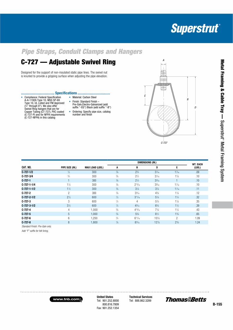
United States
Tel: 901.252.8000800.816.7809
Fax: 901.252.1354
Technical Services
Tel: 888.862.3289www.tnb.com
B-155
Pipe Straps, Conduit Clamps and Hangers
Metal Fram
ing & Cable Tray —
Superstrut® M
etal Framing System
C-727 — Adjustable Swivel RingDesigned for the support of non-insulated static pipe lines. The swivel nut is knurled to provide a gripping surface when adjusting the pipe elevation.
CAT. NO. PIPE SIZE (IN.) MAX LOAD (LBS.)
DIMENSIONS (IN.)WT. EACH
(LBS.)A B D E
C-727-1/2 1⁄2 300 3⁄8 23⁄4 31⁄16 17⁄16 .09
C-727-3/4 3⁄4 300 3⁄8 21⁄2 31⁄16 11⁄8 .10
C-727-1 1 300 3⁄8 21⁄2 33⁄16 1 .10
C-727-1-1/4 11⁄4 300 3⁄8 213⁄16 39⁄16 11⁄16 .10
C-727-1-1/2 11⁄2 300 3⁄8 31⁄8 37⁄8 11⁄16 .11
C-727-2 2 300 3⁄8 35⁄16 43⁄8 11⁄8 .12
C-727-2-1/2 21⁄2 600 1⁄2 311⁄16 51⁄8 11⁄4 .32
C-727-3 3 600 1⁄2 4 57⁄8 11⁄8 .35
C-727-3-1/2 31⁄2 600 1⁄2 45⁄16 65⁄8 11⁄2 .39
C-727-4 4 1,000 5⁄8 415⁄16 71⁄8 11⁄4 .43
C-727-5 5 1,000 5⁄8 55⁄8 81⁄2 13⁄8 .65
C-727-6 6 1,250 3⁄4 611⁄16 101⁄8 2 1.09
C-727-8 8 1,800 7⁄8 8 5⁄16 12 7⁄8 2 5⁄8 1.24
Standard Finish: Pre-Galv only.
Add “F” suffix for felt lining.
C-727
E
A
B
D(3⁄4
.................................... Specifications ...................................

www.tnb.comUnited States
Tel: 901.252.8000800.816.7809
Fax: 901.252.1354
Technical Services
Tel: 888.862.3289B-156
Pipe Straps, Conduit Clamps and Hangers
Met
al F
ram
ing
& C
able
Tra
y —
Sup
erst
rut®
Met
al F
ram
ing
Syst
em C-727-P — PVC-Coated Adjustable Swivel Ring
Designed for the support of non-insulated static pipe lines and to protect the pipe from coming into direct contact with the hanger by having the contact surface PVC coated. The swivel nut is knurled to provide a gripping surface when adjusting the pipe elevation.
CAT. NO.PIPE
SIZE (IN.)
MAX. LOAD
(LBS.)
DIMENSIONS (IN.) WT.
EACH (LBS.)A B D E
C727P 1/2 1⁄2 300 3⁄8 23⁄4 31⁄16 17⁄16 .11
C-727-P-3/4 3⁄4 300 3⁄8 21⁄2 31⁄16 11⁄8 .13
C-727-P-1 1 300 3⁄8 21⁄2 33⁄16 1 .13
C-727-P-1-1/4 11⁄4 300 3⁄8 213⁄16 39⁄16 11⁄16 .15
C-727-P-1-1/2 11⁄2 300 3⁄8 31⁄8 37⁄8 11⁄16 .17
C-727-P-2 2 300 3⁄8 35⁄16 43⁄8 11⁄8 .18
C-727-P-2-1/2 21⁄2 600 1⁄2 311⁄16 51⁄8 11⁄4 .34
C-727-P-3 3 600 1⁄2 4 57⁄8 11⁄8 .39
C-727-P-3-1/2 31⁄2 600 1⁄2 45⁄16 65⁄8 11⁄2 .42
C-727-P-4 4 1,000 5⁄8 415⁄16 71⁄8 11⁄4 .48
C-727-P-5 5 1,000 5⁄8 55⁄8 81⁄2 13⁄8 .69
C-727-P-6 6 1,250 3⁄4 611⁄16 101⁄8 2 1.13
C-727-P-8 8 1,800 7⁄8 85⁄16 127⁄8 25⁄8 1.29
Standard Finish – GoldGalv®, unless otherwise stated.
C-727-P
A
EB
D
C-727-NFPA — NFPA Swivel Ring
Designed for the support of non-insulated static pipe lines. The swivel nut is knurled to provide a gripping surface when adjusting the tubing elevation and is tapped to the reduced rod standards of NFPA.
CAT. NO.PIPE
SIZE (IN.)
MAX. LOAD
(LBS.)
DIMENSIONS (IN.) WT.
EACH (LBS.)A B D E
C-727-NFPA-1/2 1⁄2 300 3⁄8 23⁄4 31⁄16 17⁄16 .09
C-727-NFPA-3/4 3⁄4 300 3⁄8 21⁄2 31⁄16 11⁄8 .10
C-727-NFPA-1 1 300 3⁄8 21⁄2 33⁄16 1 .10
C-727-NFPA-1-1/4 11⁄4 300 3⁄8 213⁄16 39⁄16 11⁄16 .10
C-727-NFPA-1-1/2 11⁄2 300 3⁄8 31⁄8 37⁄8 11⁄16 .11
C-727-NFPA-2 2 300 3⁄8 35⁄16 43⁄8 11⁄8 .12
C-727-NFPA-2-1/2 21⁄2 525 3⁄8 311⁄16 5 11⁄4 .25
C-727-NFPA-3 3 525 3⁄8 33⁄4 59⁄16 11⁄8 .30
C-727-NFPA-3-1/2 31⁄2 525 3⁄8 45⁄16 65⁄16 11⁄2 .33
C-727-NFPA-4 4 650 3⁄8 41⁄2 7 15⁄8 .41
C-727-NFPA-5 5 1,000 1⁄2 55⁄8 83⁄8 21⁄4 .58
C-727-NFPA-6 6 1,000 1⁄2 61⁄2 913⁄16 27⁄16 .92
C-727-NFPA-8 8 1,000 1⁄2 715⁄16 121⁄4 25⁄8 1.16
Standard Finish – GoldGalv®, unless otherwise stated.
C-727-P
A
EB
D
Compliance: Federal Specification A-A-1192A Type 10, MSS SP-69 Type 10, UL Listed and FM Approved (3⁄4" through 8")
We also offer Swivel Ring hangers that are for Copper Tubing (CT-727) and for NFPA requirements (C-727-NFPA) in this catalog. Operating temperature should not exceed 140° F/60° C
Material: Carbon Steel
Finish: Standard Finish – GoldGalv®,Black (add suffix “-B”), Electro-Galvanized (add suffix “-EG”)
Ordering: Specify pipe size and catalog number
.................................... Specifications ...................................Compliance: Federal Specification A-A-1192A Type 10, MSS SP-69 Type 10, UL Listed and FM Approved (3⁄4" through 8") and NFPA standards
We also offer Swivel Ring hangers that are for standard commercial pipe (C-727), copper tubing (CT-727) and PVC coated (C-727-P) inthis catalog
Material: Carbon Steel
Finish: Standard Finish – GoldGalv®,Black (add suffix “-B”), Electro-Galvanized (add suffix “-EG”)
Ordering: Specify pipe size, catalog number and finish
.................................... Specifications ...................................

United States
Tel: 901.252.8000800.816.7809
Fax: 901.252.1354
Technical Services
Tel: 888.862.3289www.tnb.com
B-157
Pipe Straps, Conduit Clamps and Hangers
Metal Fram
ing & Cable Tray —
Superstrut® M
etal Framing System
CT-727 — Copper Tubing Swivel Ring
Designed for the support of non-insulated static copper tubing lines.The swivel nut is knurled to provide a gripping surface when adjusting the tubing elevation.
CAT. NO.PIPE
SIZE (IN.)
MAX.
LOAD (LBS.)
DIMENSIONS (IN.) WT. EACH
(LBS.)A B D E
CT727 1/2 1⁄2 300 3⁄8 23⁄8 31⁄4 111⁄16 .11
CT-727-3/4 3⁄4 300 3⁄8 23⁄8 31⁄8 13⁄8 .11
CT-727-1 1 300 3⁄8 21⁄2 31⁄8 1 .11
CT-727-1-1/4 11⁄4 300 3⁄8 23⁄4 31⁄4 15⁄16 .13
CT-727-1-1/2 11⁄2 300 3⁄8 215⁄16 35⁄8 11⁄8 .13
CT-727-2 2 300 3⁄8 35⁄16 41⁄8 11⁄16 .15
CT-727-2-1/2 21⁄2 525 3⁄8 4 45⁄8 11⁄8 .16
CT-727-3 3 525 1⁄2 49⁄16 59⁄16 15⁄16 .32
CT-727-3-1/2 31⁄2 525 1⁄2 49⁄16 57⁄8 11⁄8 .35
CT-727-4 4 650 1⁄2 59⁄16 61⁄2 13⁄16 .38
CT-727-5 5 1,000 1⁄2 61⁄4 83⁄8 15⁄8 .58
CT-727-6 6 1,000 1⁄2 73⁄16 913⁄16 21⁄4 .92
Standard Finish – GoldGalv® unless otherwise stated.
CAT. NO.TUBING
SIZE (IN.)
ROD
SIZE (IN.)
DIMENSIONS (IN.) STOCK
SIZE
MAX REC.
LOAD (LBS.)
STD.
CTN.A B C
ET727 1/2 1⁄2 3⁄8 31⁄8 23⁄4 11⁄2 16 ga x 5⁄8 400 100
ET-727-3/4 3⁄4 3⁄8 31⁄8 25⁄8 11⁄4 16 ga x 5⁄8 400 100
ET-727-1 1 3⁄8 31⁄8 21⁄2 1 16 ga x 5⁄8 400 100
ET-727-1-1/4 11⁄4 3⁄8 31⁄4 21⁄2 1 16 ga x 5⁄8 400 100
ET-727-1-1/2 11⁄2 3⁄8 37⁄8 3 11⁄4 16 ga x 5⁄8 400 100
ET-727-2 2 3⁄8 41⁄2 33⁄8 11⁄2 16 ga x 5⁄8 400 100
ET-727-2-1/2 21⁄2 3⁄8* 51⁄2 43⁄8 2 14 ga x 13⁄16 600 100
ET-727-3 3 1⁄2 63⁄8 43⁄4 2 14 ga x 13⁄16 600 100
ET-727-3-1/2 31⁄2 1⁄2 63⁄8 41⁄2 11⁄2 14 ga x 13⁄16 600 50
ET-727-4 4 1⁄2* 73⁄8 51⁄4 2 14 ga x 11⁄4 1,250 100
ET-727-5 5 5⁄8 83⁄8 53⁄4 2 12 ga x 11⁄4 1,250 25
ET-727-6 6 5⁄8 91⁄2 63⁄8 11⁄8 12 ga x 11⁄4 1,250 25
2 1⁄2" CT filled with water weighs less than 2" IP filled with water, 4" CT less than 3 1⁄2" IP with water.
2 1⁄2" CT available with 1⁄2" thread and 4" CT available with 5⁄8" thread for Government Specs.
Standard Finish – GoldGalv®, unless otherwise stated.
ET-727 Copper Sized Adjustable Ring
Standard Finish – GoldGalv® barrier for separation of dissimilar metals.Available in sizes 1⁄2" through 2". Sized for Copper Tubing.
CT-727
A
EB
D
Compliance: Federal Specification A-A-1192A Type 10, MSS SP-69 Type 10. We also offer Swivel Ring hangers that are for carbon steel pipe (C-727), PVC coated (C-727-P) and for NFPA requirements (C-727-NFPA) in this catalog
Material: Carbon Steel
Finish: Copper
Ordering: Specify copper tubing size
.................................... Specifications ...................................

www.tnb.comUnited States
Tel: 901.252.8000800.816.7809
Fax: 901.252.1354
Technical Services
Tel: 888.862.3289B-158
Pipe Straps, Conduit Clamps and Hangers
Met
al F
ram
ing
& C
able
Tra
y —
Sup
erst
rut®
Met
al F
ram
ing
Syst
em
M-718
CAT. NO.PIPE SIZE
(IN.)
MAX LOAD
(LBS.)
PIPE SIZE
A (IN.)
ROD SIZE
A (IN.) B (IN.) WT. EACH (LBS.)
M-718-3/8 3⁄8 180 1⁄4 3⁄8 13⁄16 .16
M-718-1/2 1⁄2 180 1⁄4 3⁄8 7⁄8 .17
M-718-3/4 3⁄4 180 1⁄4 3⁄8 1 .20
M-718-1 1 180 1⁄4 3⁄8 11⁄8 .21
M-718-1-1/4 11⁄4 180 1⁄4 3⁄8 17⁄16 .29
M-718-1-1/2 11⁄2 180 1⁄4 3⁄8 15⁄16 .31
M-718-2 2 180 1⁄4 3⁄8 111⁄16 .35
M-718-2-1/2 21⁄2 480 1⁄2 1⁄2 21⁄8 .57
M-718-3 3 480 1⁄2 1⁄2 27⁄16 .72
M-718-4 4 480 1⁄2 1⁄2 31⁄5 1.16
Standard Finish – EG (silver).
M-718, M-718-B — Extension Ring Hanger
M-718 — (Rod Tapped – Electro-Galvanized)M-718-B — (Rod Tapped – Plain Finish)
This split ring hanger is designed for the support of non-insulated stationary pipe lines.Also available in a two-screw design. The MT-742-R Ceiling Plate is normally used withthis product. A
B
CAT. NO. TUBE SIZE (IN.)
MAX LOAD
(LBS.)
ROD SIZE A
(IN.) B (IN.) WT. EACH (LBS.)
MT718-1/4 1⁄4 180 3⁄8 1⁄2 .10
MT-718-3/8 3⁄8 180 3⁄8 1⁄2 .12
MT-718-1/2 1⁄2 180 3⁄8 3⁄4 .13
MT-718-5/8 5⁄8 180 3⁄8 3⁄4 .14
MT-718-3/4 3⁄4 180 3⁄8 7⁄8 .15
MT-718-1 1 180 3⁄8 1 .16
MT-718-1-1/4 11⁄4 180 3⁄8 11⁄4 .19
MT-718-1-1/2 11⁄2 180 3⁄8 11⁄4 .22
MT-718-2 2 180 3⁄8 11⁄2 .27
MT-718-2-1/2 21⁄2 480 1⁄2 2 .72
MT-718-3 3 480 1⁄2 21⁄4 1.07
Standard Finish – GoldGalv®, unless otherwise stated.
MT-718
MT-718 — Copper Extension Ring Hanger
This split ring hanger is designed for the support of non-insulated copper tubing lines.The MT-718 is furnished tapped for bolt thread and is used with the MT-742-R CeilingPlate. Also available in a two-bolt design.
A
B
Material: Malleable Iron.
Finish: Standard Finish – EG (silver), Black (add suffix “-B”), Electro-Galvanized (add suffix “-EG”)
Compliance: Federal Specification A-A-1192A Type 12, MSS-SP-69 Type 12
Ordering: Specify pipe size and catalog number.
.................................... Specifications ...................................
Material: Malleable Iron
Finish: Copper
For Electro-Galvanizing pleasesee M-718.
Compliance: Federal Specification A-A-1192A Type 12, MSS-SP-69 Type 12
Ordering: Specify tube size and catalog number.
.................................... Specifications ...................................

United States
Tel: 901.252.8000800.816.7809
Fax: 901.252.1354
Technical Services
Tel: 888.862.3289www.tnb.com
B-159
Pipe Straps, Conduit Clamps and Hangers
Metal Fram
ing & Cable Tray —
Superstrut® M
etal Framing System
Seismic Bracing
(Consult Superstrut® Seismic Hanger bulletin for additional information.)
15⁄8"
2 3⁄8"
11⁄16" Dia.
41⁄2"
15⁄8"
1⁄4"
2 Holes9⁄16" Dia.
CAT. NO. C749N 5/8
Seismic Brace1,650 lb. load safety factor of 3
15⁄8"
2 3⁄8"
41⁄2"
1⁄4"
15⁄8"
CAT. NO. PIPE SIZE (IN.) ROD SIZE (IN.) ADJUSTMENT (IN.) BOLT CENTERS (IN.) STOCK SIZE (IN.) BOLT SIZE (IN.) DESIGN LOAD (LBS.) STD. CTN.
S720 3/4 3⁄4 3⁄8 15⁄8 41⁄2 3⁄16 x 11⁄4 1⁄2–11⁄4 550 10
S-720-1 1 3⁄8 11⁄2 41⁄2 3⁄16 x 11⁄4 1⁄2–11⁄4 550 10
S-720-1-1/4 11⁄4 3⁄8 13⁄8 5 3⁄16 x 11⁄4 1⁄2–11⁄4 550 10
S-720-1-1/2 11⁄2 3⁄8 11⁄2 41⁄2 3⁄16 x 11⁄4 1⁄2–11⁄4 550 10
S-720-2 2 3⁄8 11⁄2 5 1⁄4 x 11⁄4 1⁄2–11⁄4 700 10
S-720-2-1/2 21⁄2 1⁄2 21⁄8 53⁄8 1⁄4 x 11⁄4 1⁄2–11⁄4 700 10
S-720-3 3 1⁄2 21⁄4 61⁄4 1⁄4 x 11⁄4 1⁄2–11⁄4 1,100 10
S-720-3-1/2 31⁄2 1⁄2 21⁄4 63⁄4 1⁄4 x 11⁄4 1⁄2–11⁄4 1,100 10
S-720-4 4 1⁄2 21⁄4 71⁄4 1⁄4 x 11⁄4 1⁄2–11⁄4 1,300 10
S-720-5 5 5⁄8 21⁄4 81⁄2 1⁄4 x 11⁄2 5⁄8–11⁄2 1,600 10
S-720-6 6 5⁄8 21⁄4 91⁄2 1⁄4 x 11⁄2 5⁄8–11⁄2 1,600 5
S-720-8 8 3⁄4 21⁄8 111⁄2 1⁄4 x 2 3⁄4–2 2,000 5
Standard Finish – GoldGalv ®, unless otherwise stated.
15⁄16"
All braces have plastisol coating on the flat member.Plastisol insulates against vibration noise transmissionand eliminates rattle at the connection points.
Standard Finish – GoldGalv® brand. Approved for seismic applications.
CAT. NO. C749N 7/8
Seismic Brace1,650 lb. load safety factor of 3
CAT. NO. ES-142
Size: 1⁄2" x 11⁄4" Bolt Size: 1⁄2"Seismic bracing rod stiffener connector
S-720 — Adjustable Pipe Hanger
2 Holes9⁄16" Dia.
2"
13⁄16"Dia.
1⁄4"
3 11⁄16"
15⁄8"
41⁄4"
CAT. NO. C-749-N-1-1/8
Seismic Brace1,650 lb. load safety factor of 3
2 Holes9⁄16" Dia.
13⁄4"
41⁄2"
15⁄8"
1⁄4"
2 Holes9⁄16" Dia.
15⁄8"
CAT. NO. C749N
Seismic Brace1,500 lb. load safety factor of 3
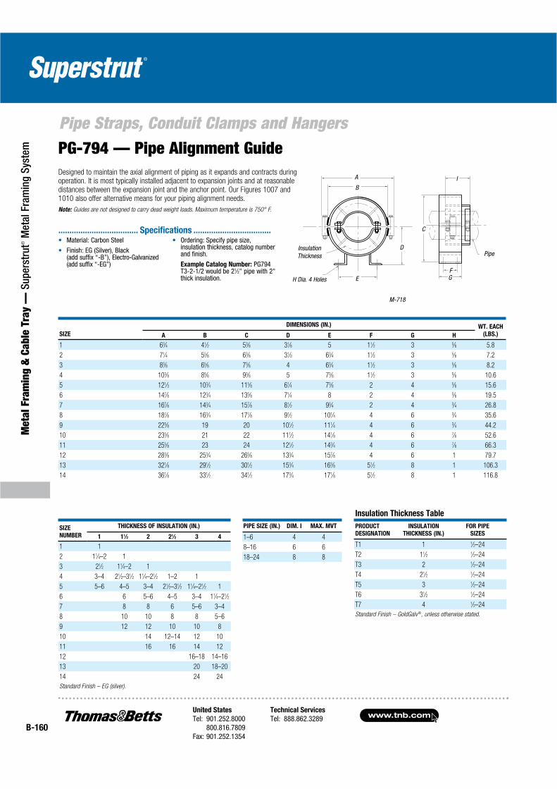
www.tnb.comUnited States
Tel: 901.252.8000800.816.7809
Fax: 901.252.1354
Technical Services
Tel: 888.862.3289B-160
Pipe Straps, Conduit Clamps and Hangers
Met
al F
ram
ing
& C
able
Tra
y —
Sup
erst
rut®
Met
al F
ram
ing
Syst
em PG-794 — Pipe Alignment GuideDesigned to maintain the axial alignment of piping as it expands and contracts during operation. It is most typically installed adjacent to expansion joints and at reasonable distances between the expansion joint and the anchor point. Our Figures 1007 and 1010 also offer alternative means for your piping alignment needs.
Note: Guides are not designed to carry dead weight loads. Maximum temperature is 750° F.
M-718
A
E
InsulationThickness
H Dia. 4 Holes
B
D
C
FG
I
Pipe
SIZE
DIMENSIONS (IN.) WT. EACH
(LBS.)A B C D E F G H
1 63⁄4 41⁄2 53⁄8 31⁄8 5 11⁄2 3 5⁄8 5.8
2 71⁄4 55⁄8 63⁄8 31⁄2 63⁄4 11⁄2 3 5⁄8 7.2
3 83⁄8 65⁄8 73⁄8 4 63⁄4 11⁄2 3 5⁄8 8.2
4 103⁄8 85⁄8 93⁄8 5 73⁄8 11⁄2 3 5⁄8 10.6
5 121⁄3 103⁄4 115⁄8 61⁄4 73⁄8 2 4 5⁄8 15.6
6 147⁄8 123⁄4 135⁄8 71⁄4 8 2 4 5⁄8 19.5
7 167⁄8 143⁄4 157⁄8 81⁄2 93⁄4 2 4 3⁄4 26.8
8 187⁄8 163⁄4 177⁄8 91⁄2 101⁄4 4 6 3⁄4 35.6
9 225⁄8 19 20 101⁄2 111⁄4 4 6 3⁄4 44.2
10 235⁄8 21 22 111⁄2 141⁄8 4 6 7⁄8 52.6
11 255⁄8 23 24 121⁄2 143⁄4 4 6 7⁄8 66.3
12 283⁄8 253⁄4 265⁄8 133⁄4 157⁄8 4 6 1 79.7
13 321⁄8 291⁄2 301⁄2 153⁄4 163⁄8 51⁄2 8 1 106.3
14 361⁄8 331⁄2 341⁄2 173⁄4 171⁄8 51⁄2 8 1 116.8
SIZE
NUMBER
THICKNESS OF INSULATION (IN.)
1 11⁄2 2 21⁄2 3 4
1 1
2 11⁄4–2 1
3 21⁄2 11⁄4–2 1
4 3–4 21⁄2–31⁄2 11⁄4–21⁄2 1–2 1
5 5–6 4–5 3–4 21⁄2–31⁄2 11⁄4–21⁄2 1
6 6 5–6 4–5 3–4 11⁄4–21⁄2
7 8 8 6 5–6 3–4
8 10 10 8 8 5–6
9 12 12 10 10 8
10 14 12–14 12 10
11 16 16 14 12
12 16–18 14–16
13 20 18–20
14 24 24
Standard Finish – EG (silver).
PIPE SIZE (IN.) DIM. I MAX. MVT
1–6 4 4
8–16 6 6
18–24 8 8
Insulation Thickness Table
PRODUCT
DESIGNATION
INSULATION
THICKNESS (IN.)
FOR PIPE
SIZES
T1 1 1⁄2–24
T2 11⁄2 1⁄2–24
T3 2 1⁄2–24
T4 21⁄2 1⁄2–24
T5 3 1⁄2–24
T6 31⁄2 1⁄2–24
T7 4 1⁄2–24
Standard Finish – GoldGalv®, unless otherwise stated.
Material: Carbon Steel
Finish: EG (Silver), Black (add suffix “-B”), Electro-Galvanized (add suffix “-EG”)
Ordering: Specify pipe size, insulation thickness, catalog number and finish.
Example Catalog Number: PG794 T3-2-1/2 would be 21⁄2" pipe with 2" thick insulation.
.................................... Specifications ...................................
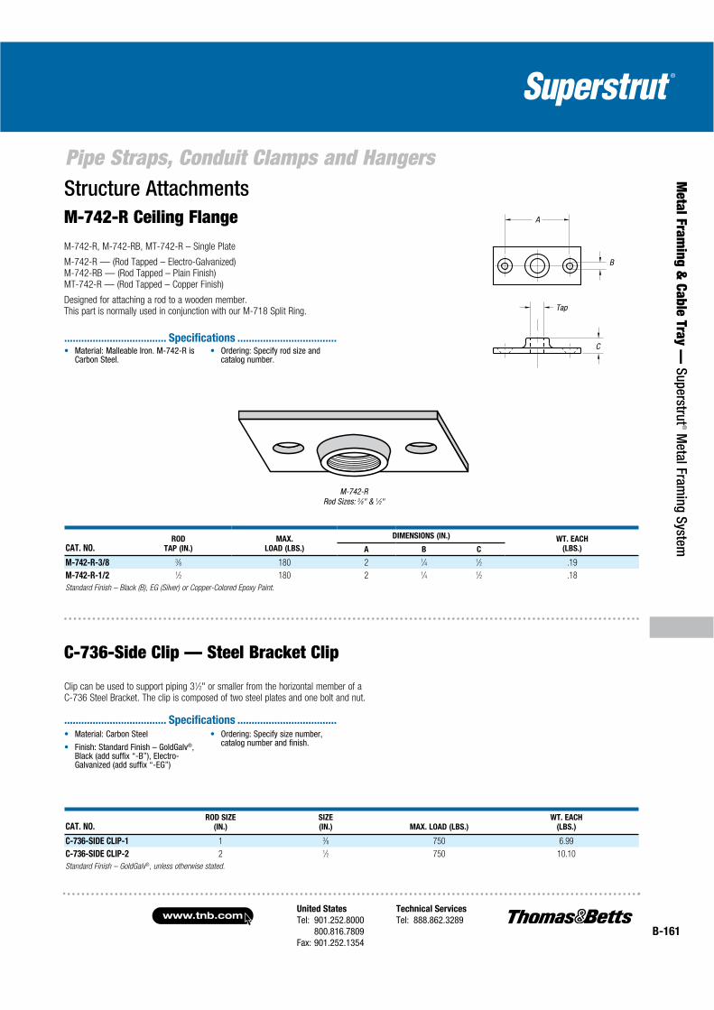
United States
Tel: 901.252.8000800.816.7809
Fax: 901.252.1354
Technical Services
Tel: 888.862.3289www.tnb.com
B-161
Pipe Straps, Conduit Clamps and Hangers
Metal Fram
ing & Cable Tray —
Superstrut® M
etal Framing System
A
B
C
Tap
CAT. NO.ROD
TAP (IN.)
MAX.
LOAD (LBS.)
DIMENSIONS (IN.) WT. EACH
(LBS.)A B C
M-742-R-3/8 3⁄8 180 2 1⁄4 1⁄2 .19
M-742-R-1/2 1⁄2 180 2 1⁄4 1⁄2 .18
Standard Finish – Black (B), EG (Silver) or Copper-Colored Epoxy Paint.
Structure AttachmentsM-742-R Ceiling Flange
M-742-R, M-742-RB, MT-742-R – Single Plate
M-742-R — (Rod Tapped – Electro-Galvanized)M-742-RB — (Rod Tapped – Plain Finish)MT-742-R — (Rod Tapped – Copper Finish)
Designed for attaching a rod to a wooden member.This part is normally used in conjunction with our M-718 Split Ring.
M-742-RRod Sizes: 3⁄8" & 1⁄2"
C-736-Side Clip — Steel Bracket Clip
Clip can be used to support piping 31⁄2" or smaller from the horizontal member of aC-736 Steel Bracket. The clip is composed of two steel plates and one bolt and nut.
CAT. NO.ROD SIZE
(IN.)
SIZE
(IN.) MAX. LOAD (LBS.)
WT. EACH
(LBS.)
C-736-SIDE CLIP-1 1 3⁄8 750 6.99
C-736-SIDE CLIP-2 2 1⁄2 750 10.10
Standard Finish – GoldGalv®, unless otherwise stated.
Material: Malleable Iron. M-742-R isCarbon Steel.
Ordering: Specify rod size and catalog number.
.................................... Specifications ...................................
Material: Carbon Steel
Finish: Standard Finish – GoldGalv®,Black (add suffix “-B”), Electro-Galvanized (add suffix “-EG”)
Ordering: Specify size number, catalog number and finish.
.................................... Specifications ...................................
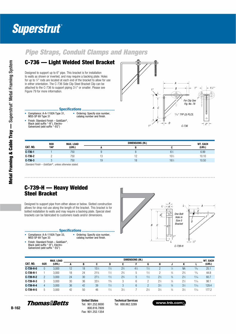
www.tnb.comUnited States
Tel: 901.252.8000800.816.7809
Fax: 901.252.1354
Technical Services
Tel: 888.862.3289B-162
Pipe Straps, Conduit Clamps and Hangers
Met
al F
ram
ing
& C
able
Tra
y —
Sup
erst
rut®
Met
al F
ram
ing
Syst
em C-736 — Light Welded Steel Bracket
Designed to support up to 6" pipe. This bracket is for installation to walls as shown or inverted, and may require a backing plate. Holes for up to 3⁄4" rods are located at each end of the bracket to allow for use in either orientation. The C-736 Side Clip Steel Bracket Clip can be attached to the C-736 to support piping 31⁄2" or smaller. Please see Figure 79 for more information.
C-736
A
B 1" 11⁄4"
2"D
13⁄16" TYP (3) PLCS.
For Clip See Fig. No. 78
CA
1"
1"
CAT. NO.ROD
TAP
MAX. LOAD
(LBS.)
DIMENSIONS (IN.) WT. EACH
(LBS.)A B C
C-736-1 1 750 9 8 61⁄2 6.99
C-736-2 2 750 13 12 101⁄2 10.10
C-736-3 3 750 19 18 161⁄2 10.50
Standard Finish – GoldGalv®, unless otherwise stated.
C-739-H — Heavy WeldedSteel Bracket
Designed to support pipe from either above or below. Slotted constructionallows for drop rod use along the length of the bracket. This bracket is forbolted installation to walls and may require a backing plate. Special steelbrackets can be fabricated to customers loads and/or dimensions.
C-739-H
CAT. NO. SIZE
MAX. LOAD
(LBS.)
DIMENSIONS (IN.) WT. EACH
(LBS.)A B C D E F G H J K L
C-739-H-0 0 3,000 12 18 151⁄4 11⁄2 23⁄4 41⁄2 11⁄2 2 1⁄4 NA 13⁄16 25.1
C-739-H-1 1 3,000 18 24 213⁄8 11⁄2 23⁄4 5 11⁄2 2 3⁄8 23⁄4 13⁄16 44.8
C-739-H-2 2 3,000 24 30 271⁄2 11⁄2 23⁄4 5 11⁄2 21⁄2 3⁄8 21⁄2 11⁄16 60.7
C-739-H-3 3 3,000 30 36 331⁄4 15⁄8 3 6 2 21⁄2 3⁄8 21⁄2 11⁄16 98.1
C-739-H-4 4 3,000 36 42 39 11⁄2 3 6 2 31⁄2 3⁄8 31⁄2 11⁄16 129.4
C-739-H-5 5 3,000 42 50 46 11⁄2 31⁄2 7 21⁄2 31⁄2 3⁄8 31⁄2 11⁄16 177.2
L
L A
E
J
B C
1"
G
H
FKL
L
D
One Bolt Hole in Size 0
Bracket
1⁄2"
Compliance: A-A-1192A Type 31, MSS-SP 69 Type 31
Finish: Standard Finish – GoldGalv®,Black (add suffix “-B”), Electro-Galvanized (add suffix “-EG”)
Ordering: Specify size number, catalog number and finish.
.................................... Specifications ...................................
Compliance: A-A-1192A Type 33, MSS-SP 69 Type 33
Finish: Standard Finish – GoldGalv®,Black (add suffix “-B”), Electro-Galvanized (add suffix “-EG”)
Ordering: Specify size number, catalog number and finish.
.................................... Specifications ...................................

United States
Tel: 901.252.8000800.816.7809
Fax: 901.252.1354
Technical Services
Tel: 888.862.3289www.tnb.com
B-163
Pipe Straps, Conduit Clamps and Hangers
Metal Fram
ing & Cable Tray —
Superstrut® M
etal Framing System
3"
7⁄8"
7⁄16" Dia.
11⁄2"
PG-795 — Pipe Block
Standard Finish — Black (B).
Pipe AttachmentsH-115, H-115SS — Standard U-Bolt
Our standard U-Bolts are recommended for use as supports or guides for piping. They are supplied with four hex nuts. The H-115SS is recommended for support of stainless steel piping. Please specify the grade of stainless steel you require when ordering. Load Ratings shown are for Carbon Steel. PVC coating should not exceed 140° F/60° C.
H-115
A B
C
E
D
H-115-1/2
CAT. NO.
PIPE
SIZE
(IN.)
MAX. LOAD (LBS.)MAX. SIDE
LOAD (LBS.)
650° F/343° C
WT.
EACH
(LBS.)
650° F/
343° C
750° F/
399° C
DIMENSIONS (IN.)
A B C D E
H-115-1/2 1⁄2 485 435 63 1⁄4 13⁄8 11⁄8 23⁄4 21⁄8 .11
H-115-3/4 3⁄4 485 435 63 1⁄4 11⁄8 13⁄8 23⁄4 21⁄8 .12
H-115-1 1 485 435 63 1⁄4 13⁄8 15⁄8 23⁄4 21⁄8 .12
H-115-1/2 1⁄2 1,200 1,070 316 3⁄8 13⁄8 11⁄4 23⁄4 21⁄8 .16
H-115-3/4 3⁄4 1,200 1,070 240 3⁄8 11⁄8 11⁄2 23⁄4 21⁄8 .16
H-115-1 1 1,200 1,070 186 3⁄8 13⁄8 13⁄4 23⁄4 21⁄8 .19
H-115-1-1/4 11⁄4 1,220 1,090 194 3⁄8 13⁄4 21⁄8 27⁄8 21⁄8 .28
H-115-1-1/2 11⁄2 1,220 1,090 194 3⁄8 2 23⁄8 3 21⁄2 .30
H-115-2 2 1,220 1,090 194 3⁄8 21⁄2 27⁄8 31⁄4 21⁄2 .33
H-115-2-1/2 21⁄2 2,260 2,020 184 1⁄2 3 31⁄2 33⁄4 3 .70
H-115-3 3 2,260 2,020 184 1⁄2 35⁄8 41⁄8 4 3 .78
H-115-3-1/2 31⁄2 2,260 2,020 184 1⁄2 41⁄8 45⁄8 41⁄2 3 .84
H-115-4 4 2,260 2,020 184 1⁄2 45⁄8 51⁄8 41⁄2 3 .90
Materials: Carbon Steel,Stainless Steel
Compliance: Federal Specification A-A-1192A Type 24, MSS-SP 69 Type 24, and BSPSS-BS3974
Finish: Standard Finish – GoldGalv®,Black (add suffix “-B”), Electro-Galvanized (add suffix “-EG”), SS (add suffix SS), SS6 = 316
Side loads are given for the H-115 for a maximum temperature of 650° F/343° C.
When the loading condition requires the simultaneous application of a normal load and side load, the following interaction equation must be used to determine if the H-115 can be used.
(Actual Load / Maximum Design Load) + (Actual Side Load/Maximum Side Load). The result of this equation cannot exceed the value of 1.0 if the H-115 is to be used.
Ordering: Specify pipe size, catalog number and finish.
.................................... Specifications ...................................

www.tnb.comUnited States
Tel: 901.252.8000800.816.7809
Fax: 901.252.1354
Technical Services
Tel: 888.862.3289B-164
Pipe Straps, Conduit Clamps and Hangers
Met
al F
ram
ing
& C
able
Tra
y —
Sup
erst
rut®
Met
al F
ram
ing
Syst
em Beam AttachmentsM-750 — Side Beam BracketDesigned for bolt connections.
CAT. NO.
MAX LOAD (LBS.)WITH
BOLT TO
STEEL
DIMENSIONS (IN.) WT.
EACH
(LBS.)
ROD SIZE
(IN.)
WITH LAG
SCREW C D F G
M-750-3/8 3⁄8 390 610 5⁄8 17⁄167⁄16
7⁄8 .26
M-750-1/2 1⁄2 640 1,130 3⁄4 17⁄8 9⁄16 13⁄16 .54
M-750-5/8 5⁄8 760 1,810 7⁄8 21⁄8 3⁄4 17⁄16 .94
CAT. NO. SIZE (IN.)
MAX LOAD
(LBS.)
DIMENSIONS (IN.) WT.
EACH
(LBS.)A B C
M-762-3/8 3⁄8 rod 250 23⁄8 3⁄4 3⁄4 .13
M-762-1/2 1⁄2 rod 480 23⁄4 3⁄4 3⁄4 .25
M-762-1/4 1⁄4 pipe 250 23⁄4 3⁄4 3⁄4 .25
M-762
M-762 — Side Beam ConnectorDesigned for use on buildings of wood construction. They can be secured to the side of beams or joists by means of our Figure 166 Drive Screws (ordered separately).
A
B
C
G
C
D
F
F
M-750
CAT. NO. ROD SIZE A (IN.) HOLE SIZE (IN.)
DIMENSIONS (IN.)
STOCK
SIZE (IN.)
DESIGN
LOAD
(LBS.)
STD.
CTN.B C D E F
C-747-3/8B 3⁄8B 7⁄16 23⁄4 37⁄8 47⁄8 7⁄16 21⁄8 1⁄4 x 11⁄4 610 50
C-747-1/2B 1⁄2B 9⁄16 31⁄8 43⁄4 6 9⁄16 25⁄163⁄8 x 11⁄2 1,130 50
C-747-5/8B 5⁄8B 11⁄16 31⁄8 43⁄4 6 9⁄16 23⁄163⁄8 x 11⁄2 1,810 50
C-747-3/4B 3⁄4B 13⁄16 311⁄16 61⁄4 73⁄4 11⁄16 29⁄161⁄2 x 2 2,710 50
C-747-7/8B 7⁄8B 15⁄16 33⁄4 63⁄8 81⁄4 13⁄16 21⁄2 1⁄2 x 2 3,770 50
Standard Finish — Black (B).
Order by Cat. No., rod size.
A
FEB
C
DC-747 — Adjustable Beam AttachmentFor attachment to timber with coach screws or to the bottom of beams with bolts.
C-747
®
....................................Specifications....................................
®
....................................Specifications....................................

United States
Tel: 901.252.8000800.816.7809
Fax: 901.252.1354
Technical Services
Tel: 888.862.3289www.tnb.com
B-165
Pipe Straps, Conduit Clamps and Hangers
Metal Fram
ing & Cable Tray —
Superstrut® M
etal Framing System
CAT. NO. ROD SIZE (IN.)
MAX LOAD (LBS.)
650° F/343° C B (IN.)
WT. EACH
(LBS.)
F-112-3/8 3⁄8 610 71⁄8 .30
F-112-1/2 1⁄2 1,130 71⁄2 .60
F-112-5/8 5⁄8 1,810 77⁄8 1.00
F-112-3/4 3⁄4 2,710 81⁄4 1.20
F-112-7/8 7⁄8 3,370 85⁄8 1.90
F-112-1 1 4,960 9 2.50
F-112-1-1/4 11⁄4 8,000 91⁄8 3.80
F-112-1-1/2 11⁄2 11,630 93⁄4 5.70
F-112-1-3/4 13⁄4 15,700 103⁄8 8.20
F-112-2 2 20,700 11 14.20
F-112-2-1/4 21⁄4 27,200 127⁄8 27.00
F-112-2-1/2 21⁄2 33,500 131⁄2 33.00
Standard Finish – GoldGalv®, unless otherwise stated.
Rods and Rod Attachments
F-112 — Turnbuckle
Used to connect right- and left-hand threaded rods together and provide for adjustment.
CAT. NO.ROD SIZE
(IN.)
MAX LOAD
(LBS.)
DIMENSIONS (IN.)WT. EACH
(LBS.)B C G H
M-129-3/8 3⁄8 610 11⁄4 21⁄8 1⁄2 1⁄2 .20
M-129-1/2 1⁄2 1,130 13⁄8 23⁄8 5⁄8 1⁄2 .40
M-129-5/8 5⁄8 1,810 11⁄2 21⁄2 5⁄8 1⁄2 .44
M-129-3/4 3⁄4 2,710 13⁄4 27⁄8 5⁄8 1⁄2 .65
M-129-7/8 7⁄8 2,950 17⁄8 3 3⁄4 9⁄16 .78
Standard Finish – GoldGalv®, unless otherwise stated.
M-129 — Extension Piece
Designed for attaching rods to the M-732-EXT Clamp and similar types of attachments.
M-129
C
B
H
A
F-112
A
B 6"3" Rod
Take Out
®
....................................Specifications....................................
®
....................................Specifications....................................

www.tnb.comUnited States
Tel: 901.252.8000800.816.7809
Fax: 901.252.1354
Technical Services
Tel: 888.862.3289B-166
Pipe Straps, Conduit Clamps and Hangers
Met
al F
ram
ing
& C
able
Tra
y —
Sup
erst
rut®
Met
al F
ram
ing
Syst
em
Recommended for attachment to the bottom of beams when little or no pipe movement is expected. C-780 W/HWB is recommended for attachment to the bottom of beams, when pipe movement is expected. A bolt and nut or pin is supplied. A pin with cotters is normally supplied for rod sizes over 1".
C-780
H
E
S
C
E1
R
S
C
Rod Size A
Structure Attachments
C-780 W/OB, C-780 W/HWB — Welded Beam Attachment
CAT. NO.
ROD
SIZE
(IN.)
MAX. LOAD (LBS.)
650° F/
343° C
BOLT OR
PIN SIZE (IN.)
C
(IN.)
ROD TAKEOUT
C-780 W/OB
E (IN.)
ROD TAKEOUT
C-780 W/HWB
E1 (IN.)
H
(IN.)
R
(IN.)
S
(IN.)
WT. EACH (LBS.)
C-780 W/OB
W/O B&N
C-780 W/HWB
W B&N
C-780-3/8 3⁄8 610 1⁄2 27⁄8 17⁄8 2 9⁄167⁄8 11⁄4 .96 1.20
C-780-1/2 1⁄2 1,130 5⁄8 27⁄8 13⁄4 2 11⁄167⁄8 11⁄4 .96 1.20
C-780-5/8 5⁄8 1,810 3⁄4 27⁄8 13⁄4 2 13⁄167⁄8 11⁄4 .96 1.60
C-780-3/4 3⁄4 2,710 7⁄8 31⁄8 11⁄8 2 115⁄16 11⁄8 21⁄8 1.90 2.80
C-780-7/8 7⁄8 3,770 1 41⁄4 25⁄8 3 11⁄8 11⁄4 21⁄8 2.50 3.90
C-780-1 1 4,960 11⁄8 41⁄2 3 31⁄2 11⁄4 11⁄2 27⁄8 4.30 6.30
C-780-1-1/4 11⁄4 8,000 13⁄8 5 2 3 11⁄2 2 3 8.10 10.20
C-780-1-1/2 11⁄2 11,600 15⁄8 51⁄2 21⁄2 4 13⁄4 21⁄2 3 15.60 19.00
C-780-1-3/4 13⁄4 15,700 17⁄8 73⁄4 23⁄4 5 2 23⁄4 33⁄4 18.70 24.20
C-780-2 2 20,700 21⁄4 81⁄4 N/A 5 23⁄8 31⁄4 33⁄4 — 30.60
C-780-2-1/4 21⁄4 27,200 21⁄2 93⁄4 N/A 61⁄4 25⁄8 31⁄2 33⁄4 — 36.80
C-780-2-1/2 21⁄2 33,500 21⁄2 93⁄4 N/A 61⁄4 27⁄8 33⁄4 33⁄4 — 39.70
C-780-2-3/4 23⁄4 41,580 3 93⁄4 N/A 53⁄4 31⁄8 4 33⁄4 — 39.70
C-780-3 3 50,580 31⁄4 101⁄4 N/A 61⁄4 33⁄8 4 33⁄4 — 49.00
C-780-3-1/4 31⁄4 71,280 31⁄2 111⁄2 N/A 7 35⁄8 41⁄2 41⁄4 — 67.60
C-780-3-1/2 31⁄2 71,280 33⁄4 12 N/A 71⁄2 37⁄8 41⁄2 41⁄4 — 79.30
Compliance: Federal Specification A-A-1192A Type 22, MSS SP-69 Type 22 and BSPSS-BS3974
Material: Carbon Steel
Finish: Standard Finish – GoldGalv®,Black (add suffix “-B”), Electro-Galvanized (add suffix “-EG”)
Ordering: Specify catalog number, rod size and finish.
.................................... Specifications ...................................
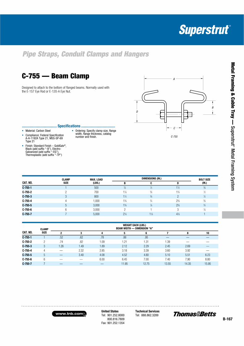
United States
Tel: 901.252.8000800.816.7809
Fax: 901.252.1354
Technical Services
Tel: 888.862.3289www.tnb.com
B-167
Pipe Straps, Conduit Clamps and Hangers
Metal Fram
ing & Cable Tray —
Superstrut® M
etal Framing System
C-755 — Beam Clamp
C-755
A
B
C
D
CAT. NO.CLAMP
SIZE
MAX. LOAD
(LBS.)
DIMENSIONS (IN.) BOLT SIZE
(IN.)B C D
C-755-1 1 500 7⁄8 1⁄2 11⁄2 3⁄8
C-755-2 2 700 11⁄8 5⁄8 13⁄4 1⁄2
C-755-3 3 800 11⁄4 5⁄8 2 1⁄2
C-755-4 4 1,000 13⁄8 3⁄4 23⁄8 5⁄8
C-755-5 5 3,000 15⁄8 7⁄8 25⁄8 3⁄4
C-755-6 6 3,000 2 1 3 7⁄8
C-755-7 7 5,000 21⁄8 11⁄8 41⁄8 1
CAT. NO.CLAMP
SIZE
WEIGHT EACH (LBS.)
BEAM WIDTH — DIMENSION “A”
2 3 4 5 6 7 8 10
C-755-1 1 .52 .62 .78 .88 .95 — — —
C-755-2 2 .74 .82 1.09 1.21 1.31 1.39 — —
C-755-3 3 1.26 1.49 1.89 2.12 2.29 2.45 2.69 —
C-755-4 4 — 2.32 2.85 3.18 3.39 3.60 3.92 —
C-755-5 5 — 3.40 4.08 4.52 4.80 5.10 5.51 6.23
C-755-6 6 — — 6.00 6.45 7.00 7.40 7.90 8.80
C-755-7 7 — — — 11.95 12.75 13.55 14.35 15.95
Designed to attach to the bottom of flanged beams. Normally used with the E-157 Eye Rod or E-120-A Eye Nut.
Material: Carbon Steel
Compliance: Federal Specification A-A-1192A Type 21, MSS-SP-69 Type 21
Finish: Standard Finish – GoldGalv®,Black (add suffix “-B”), Electro-Galvanized (add suffix “-EG”), Thermoplastic (add suffix “-TP”)
Ordering: Specify clamp size, flange width, flange thickness, catalog number and finish.
.................................... Specifications ...................................

www.tnb.comUnited States
Tel: 901.252.8000800.816.7809
Fax: 901.252.1354
Technical Services
Tel: 888.862.3289B-168
Pipe Straps, Conduit Clamps and Hangers
Met
al F
ram
ing
& C
able
Tra
y —
Sup
erst
rut®
Met
al F
ram
ing
Syst
em M-732-H — Steel Beam Clamp with Weldless Eyenut
M-732-H
A
E
BeamFlangeWidth
CAT. NO.CLAMP
SIZE
MAX.
LOAD
(LBS.)
MAX.
ROD SIZE
A (IN.)
BEAM
WIDTH
BODY
SIZE
(IN.)
MAX.
FLANGE
THICKNESS (IN.)
WT.
EACH
(LBS.)
M-732-H-1 1 2,710 3⁄4 3–8 25⁄32 .6 5.5
M-732-H-2 2 4,960 1 3–8 25⁄32 .6 5.5
M-732-H-3 3 4,960 1 4–11 27⁄32 .6 9.0
M-732-H-4 4 4,960 1 4–12 29⁄32 1.03 29.0
M-732-H-5 5 4,960 1 11–15 1⁄64 1.03 33.3
M-732-H-6 6 11,500 11⁄2 4–12 29⁄32 1.03 29.0
M-732-H-7 7 11,500 11⁄2 11–15 1⁄64 1.03 33.3
M-732-H-8 8 11,500 2 4–12 29⁄32 1.03 29.0
CAT. NO.CLAMP
SIZE
BODY SIZE
(IN.)
DIMENSIONS (IN.)
3 4 5 6 7 8 9 10 11 12 13 14 15
M-732-H-1 1 25⁄32 53⁄16 51⁄8 5 413⁄16 43⁄8 315⁄16 — — — — — — —
M-732-H-2 2 25⁄32 53⁄16 51⁄8 5 413⁄16 43⁄8 315⁄16 — — — — — — —
M-732-H-3 3 27⁄32 — 81⁄4 81⁄8 81⁄8 77⁄8 77⁄8 73⁄8 7 61⁄2 — — — —
M-732-H-4 4 27⁄32 — 85⁄8 85⁄8 81⁄2 83⁄8 81⁄8 77⁄8 75⁄8 7 67⁄8 — — —
M-732-H-5 5 1⁄64 — — — — — — — — 91⁄2 91⁄4 87⁄8 83⁄8 77⁄8
M-732-H-6 6 3⁄8 — 85⁄8 85⁄8 81⁄2 83⁄8 81⁄8 77⁄8 75⁄8 7 67⁄8 — — —
M-732-H-7 7 1⁄64 — — — — — — — — 97⁄8 91⁄2 91⁄8 87⁄8 81⁄8
M-732-H-8 8 3⁄8 — 115⁄8 111⁄2 111⁄2 113⁄8 111⁄8 107⁄8 107⁄8 101⁄2 10 — — —
The M-732-H beam clamp with eyenut is used for support where some movement is expected and welding to the structure is prohibited. The clamping effect is produced by the “ice-tong” action of the arms and is locked in place by the through bolt located just under the beam flange.
®
.................................... Specifications ...................................
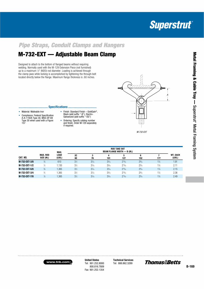
United States
Tel: 901.252.8000800.816.7809
Fax: 901.252.1354
Technical Services
Tel: 888.862.3289www.tnb.com
B-169
Pipe Straps, Conduit Clamps and Hangers
Metal Fram
ing & Cable Tray —
Superstrut® M
etal Framing System
M-732-EXT — Adjustable Beam ClampDesigned to attach to the bottom of flanged beams without requiring welding. Normally used with the M-129 Extension Piece (not furnished) up to a maximum 7⁄8" (M20) rod diameter. Loading is achieved through the clamp jaws while locking is accomplished by tightening the through-bolt located directly below the flange. Maximum flange thickness is .60 inches.
M-732-EXT
A
CAT. NO.MAX. ROD
SIZE (IN.)
MAX.
LOAD
(LBS.)
ROD TAKE OUT
BEAM FLANGE WIDTH — B (IN.)
WT. EACH
(LBS.)2C
60
3
76
4
101
5
127
6
152
7
177
M-732-EXT-3/8 3⁄8 610 31⁄2 37⁄16 35⁄16 215⁄16 29⁄16 17⁄8 1.91
M-732-EXT-1/2 1⁄2 1,130 31⁄2 37⁄16 35⁄16 215⁄16 29⁄16 17⁄8 2.11
M-732-EXT-5/8 5⁄8 1,365 31⁄2 37⁄16 35⁄16 215⁄16 29⁄16 17⁄8 2.15
M-732-EXT-3/4 3⁄4 1,365 31⁄2 37⁄16 35⁄16 215⁄16 29⁄16 17⁄8 2.36
M-732-EXT-7/8 7⁄8 1,365 31⁄2 37⁄16 35⁄16 215⁄16 29⁄16 17⁄8 2.49
®
.................................... Specifications ...................................
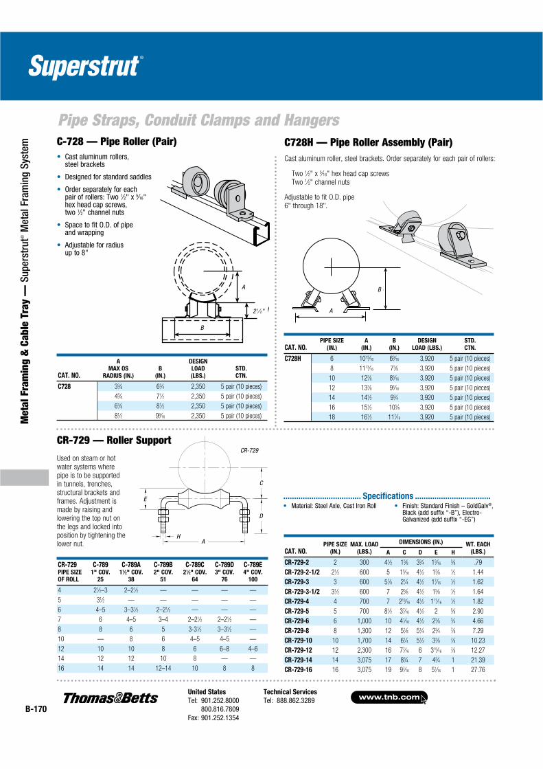
www.tnb.comUnited States
Tel: 901.252.8000800.816.7809
Fax: 901.252.1354
Technical Services
Tel: 888.862.3289B-170
Pipe Straps, Conduit Clamps and Hangers
Met
al F
ram
ing
& C
able
Tra
y —
Sup
erst
rut®
Met
al F
ram
ing
Syst
em
B
A
C-728 — Pipe Roller (Pair) Cast aluminum rollers, steel brackets
Designed for standard saddles
Order separately for each pair of rollers: Two 1⁄2" x 5⁄16"hex head cap screws,two 1⁄2" channel nuts
Space to fit O.D. of pipe and wrapping
Adjustable for radius up to 8"
CAT. NO.
A
MAX OS
RADIUS (IN.)
B
(IN.)
DESIGN
LOAD
(LBS.)
STD.
CTN.
C728 33⁄8 63⁄4 2,350 5 pair (10 pieces)
45⁄8 71⁄2 2,350 5 pair (10 pieces)
63⁄8 81⁄2 2,350 5 pair (10 pieces)
81⁄2 99⁄16 2,350 5 pair (10 pieces)
C728H — Pipe Roller Assembly (Pair)Cast aluminum roller, steel brackets. Order separately for each pair of rollers:
Two 1⁄2" x 5⁄16" hex head cap screwsTwo 1⁄2" channel nuts
Adjustable to fit O.D. pipe 6" through 18".
CAT. NO.PIPE SIZE
(IN.)
A
(IN.)
B
(IN.)
DESIGN
LOAD (LBS.)
STD.
CTN.
C728H 6 1013⁄16 69⁄16 3,920 5 pair (10 pieces)
8 1113⁄16 73⁄8 3,920 5 pair (10 pieces)
10 127⁄8 85⁄16 3,920 5 pair (10 pieces)
12 137⁄8 93⁄16 3,920 5 pair (10 pieces)
14 141⁄2 93⁄4 3,920 5 pair (10 pieces)
16 151⁄2 105⁄8 3,920 5 pair (10 pieces)
18 161⁄2 117⁄16 3,920 5 pair (10 pieces)
B
A
2-1⁄2”21⁄ 2"
CR-729 — Roller Support
CR-729PIPE SIZE
OF ROLL
C-7891" COV.
25
C-789A11⁄2" COV.
38
C-789B2" COV.
51
C-789C21⁄2" COV.
64
C-789D3" COV.
76
C-789E4" COV.
100
4 21⁄2–3 2–21⁄2 — — — —
5 31⁄2 — — — — —
6 4–5 3–31⁄2 2–21⁄2 — — —
7 6 4–5 3–4 2–21⁄2 2–21⁄2 —
8 8 6 5 3-31⁄2 3–31⁄2 —
10 — 8 6 4–5 4–5 —
12 10 10 8 6 6–8 4–6
14 12 12 10 8 — —
16 14 14 12–14 10 8 8
CR-729
AH
E
C
D
Used on steam or hot water systems where pipe is to be supported in tunnels, trenches, structural brackets and frames. Adjustment is made by raising and lowering the top nut on the legs and locked into position by tightening the lower nut.
CAT. NO.PIPE SIZE
(IN.)
MAX. LOAD
(LBS.)
DIMENSIONS (IN.) WT. EACH
(LBS.)A C D E H
CR-729-2 2 300 41⁄2 15⁄8 33⁄4 13⁄163⁄8 .79
CR-729-2-1/2 21⁄2 600 5 15⁄16 41⁄2 13⁄8 1⁄2 1.44
CR-729-3 3 600 57⁄8 21⁄4 41⁄2 17⁄161⁄2 1.62
CR-729-3-1/2 31⁄2 600 7 25⁄8 41⁄2 15⁄8 1⁄2 1.64
CR-729-4 4 700 7 213⁄16 41⁄2 111⁄161⁄2 1.82
CR-729-5 5 700 81⁄2 37⁄16 41⁄2 2 5⁄8 2.90
CR-729-6 6 1,000 10 41⁄16 41⁄2 23⁄8 3⁄4 4.66
CR-729-8 8 1,300 12 51⁄8 51⁄4 23⁄4 7⁄8 7.29
CR-729-10 10 1,700 14 61⁄4 51⁄2 33⁄8 7⁄8 10.23
CR-729-12 12 2,300 16 77⁄16 6 315⁄167⁄8 12.27
CR-729-14 14 3,075 17 83⁄4 7 43⁄4 1 21.39
CR-729-16 16 3,075 19 97⁄16 8 51⁄16 1 27.76
Material: Steel Axle, Cast Iron Roll Finish: Standard Finish – GoldGalv®,Black (add suffix “-B”), Electro-Galvanized (add suffix “-EG”)
.................................... Specifications ...................................
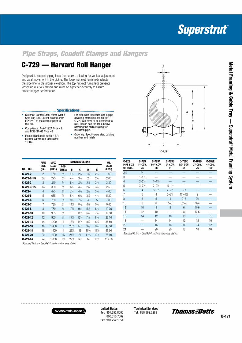
United States
Tel: 901.252.8000800.816.7809
Fax: 901.252.1354
Technical Services
Tel: 888.862.3289www.tnb.com
B-171
Pipe Straps, Conduit Clamps and Hangers
Metal Fram
ing & Cable Tray —
Superstrut® M
etal Framing System
C-729 — Harvard Roll HangerDesigned to support piping lines from above, allowing for vertical adjustment and axial movement in the piping. The lower nut (not furnished) adjusts the pipe line to the proper elevation. The top nut (not furnished) preventsloosening due to vibration and must be tightened securely to assureproper hanger performance.
C-729
A
EB
D
C
LC
CAT. NO.
PIPE
SIZE
(IN.)
MAX.
LOAD
(LBS.)
DIMENSIONS (IN.) WT.
EACH
(LBS.)ROD
SIZE A B C D E
C-729-2 2 150 1⁄2 41⁄4 23⁄4 15⁄8 25⁄8 1.60
C-729-2-1/2 21⁄2 225 1⁄2 47⁄8 31⁄4 2 27⁄8 2.00
C-729-3 3 310 1⁄2 61⁄4 37⁄8 21⁄4 31⁄8 2.30
C-729-3-1/2 31⁄2 390 1⁄2 67⁄8 41⁄2 25⁄8 31⁄2 2.50
C-729-4 4 475 5⁄8 71⁄2 47⁄8 27⁄8 35⁄8 4.00
C-729-5 5 685 5⁄8 83⁄8 63⁄8 31⁄2 41⁄2 5.30
C-729-6 6 780 3⁄4 97⁄8 75⁄8 4 5 7.00
C-729-7 7 780 3⁄4 111⁄8 81⁄2 43⁄4 51⁄4 9.40
C-729-8 8 780 7⁄8 125⁄8 91⁄2 51⁄8 61⁄8 12.30
C-729-10 10 965 7⁄8 15 111⁄4 61⁄4 71⁄4 19.30
C-729-12 12 965 7⁄8 171⁄8 131⁄2 71⁄2 83⁄8 23.10
C-729-14 14 1,200 1 183⁄8 145⁄8 83⁄8 83⁄4 35.50
C-729-16 16 1,400 1 201⁄2 171⁄4 91⁄2 93⁄4 46.50
C-729-18 18 1,400 1 231⁄8 19 101⁄2 111⁄2 57.00
C-729-20 20 1,600 11⁄4 241⁄2 21 115⁄8 121⁄4 75.90
C-729-24 24 1,800 11⁄2 297⁄8 243⁄4 14 153⁄4 119.30
Standard Finish – GoldGalv®, unless otherwise stated.
C-729PIPE SIZE
OF ROLL
C-7891" COV.
25
C-789A11⁄2" COV.
38
C-789B2" COV.
51
C-789C21⁄2" COV.
64
C-789D3" COV.
76
C-789E4" COV.
100
21⁄2 3⁄4 — — — — —
3 1–11⁄2 — — — — —
4 2–21⁄2 1–11⁄2 — — — —
5 3–31⁄2 2–21⁄2 3⁄4–11⁄2 — — —
6 4 3–31⁄2 2–21⁄2 3⁄4–1 — —
7 5 4 3–31⁄2 11⁄4–11⁄2 2 —
8 6 5 4 2–3 21⁄2 —
10 8 6 5–6 31⁄2–5 3–4 —
12 10 8 8 6 5–6 —
14 12 10 — 8 5–6 —
16 14 12 10 10 8 8
18 — 14 14 12 12 10
20 — 16 16 14 14 12
24 — 20 20 18 18 16
Standard Finish – GoldGalv®, unless otherwise stated.
Material: Carbon Steel frame with a Cast Iron Roll. Do not exceed 450° F/232° C at the contact point tothe roll.
Compliance: A-A-1192A Type 43 and MSS-SP-69 Type 43
Finish: Black (add suffix “-B”), Electro-Galvanized (add suffix “-HDG”)
For pipe with insulation and a pipe covering protection saddle the C-729 will have to be oversized to suit. Please see the table below showing the correct sizing for insulated pipe.
Ordering: Specify pipe size, catalog number and finish.
.................................... Specifications ...................................
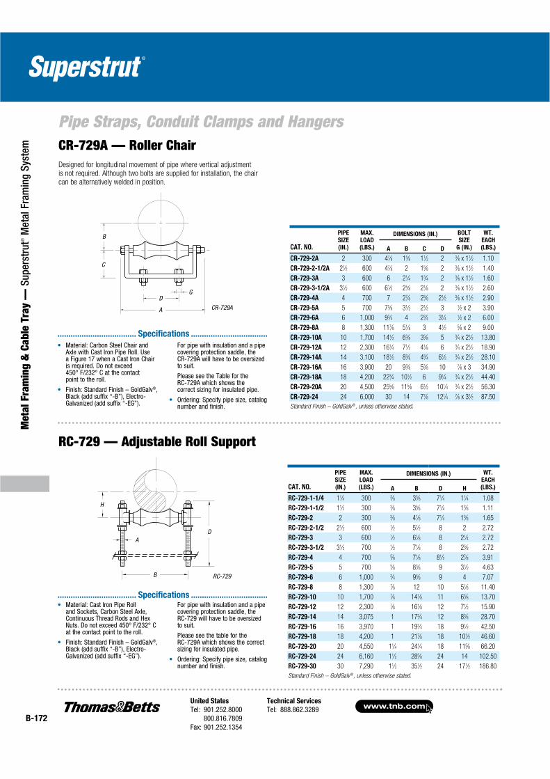
www.tnb.comUnited States
Tel: 901.252.8000800.816.7809
Fax: 901.252.1354
Technical Services
Tel: 888.862.3289B-172
Pipe Straps, Conduit Clamps and Hangers
Met
al F
ram
ing
& C
able
Tra
y —
Sup
erst
rut®
Met
al F
ram
ing
Syst
em
RC-729 — Adjustable Roll Support
CR-729A — Roller ChairDesigned for longitudinal movement of pipe where vertical adjustment is not required. Although two bolts are supplied for installation, the chair can be alternatively welded in position.
A
B
D
H
RC-729
A
D
B
C
G
CR-729A
CAT. NO.
PIPE
SIZE
(IN.)
MAX.
LOAD
(LBS.)
DIMENSIONS (IN.) BOLT
SIZE
G (IN.)
WT.
EACH
(LBS.)A B C D
CR-729-2A 2 300 47⁄8 15⁄8 11⁄2 2 3⁄8 x 11⁄2 1.10
CR-729-2-1/2A 21⁄2 600 47⁄8 2 15⁄8 2 3⁄8 x 11⁄2 1.40
CR-729-3A 3 600 6 21⁄4 13⁄4 2 3⁄8 x 11⁄2 1.60
CR-729-3-1/2A 31⁄2 600 61⁄2 25⁄8 21⁄8 2 3⁄8 x 11⁄2 2.60
CR-729-4A 4 700 7 27⁄8 23⁄8 21⁄2 3⁄8 x 11⁄2 2.90
CR-729-5A 5 700 75⁄8 31⁄2 21⁄2 3 1⁄2 x 2 3.90
CR-729-6A 6 1,000 93⁄4 4 23⁄4 31⁄4 1⁄2 x 2 6.00
CR-729-8A 8 1,300 117⁄8 51⁄8 3 41⁄2 5⁄8 x 2 9.00
CR-729-10A 10 1,700 141⁄2 63⁄8 35⁄8 5 3⁄4 x 21⁄2 13.80
CR-729-12A 12 2,300 161⁄4 71⁄2 41⁄8 6 3⁄4 x 21⁄2 18.90
CR-729-14A 14 3,100 181⁄2 83⁄8 43⁄4 61⁄2 3⁄4 x 21⁄2 28.10
CR-729-16A 16 3,900 20 93⁄8 53⁄8 10 7⁄8 x 3 34.90
CR-729-18A 18 4,200 223⁄4 101⁄2 6 91⁄4 3⁄4 x 21⁄2 44.40
CR-729-20A 20 4,500 255⁄8 115⁄8 61⁄2 101⁄4 3⁄4 x 21⁄2 56.30
CR-729-24 24 6,000 30 14 77⁄8 121⁄4 7⁄8 x 31⁄2 87.50
Standard Finish – GoldGalv®, unless otherwise stated.
CAT. NO.
PIPE
SIZE
(IN.)
MAX.
LOAD
(LBS.)
DIMENSIONS (IN.) WT.
EACH
(LBS.)A B D H
RC-729-1-1/4 11⁄4 300 3⁄8 33⁄8 71⁄4 11⁄4 1.08
RC-729-1-1/2 11⁄2 300 3⁄8 35⁄8 71⁄4 13⁄8 1.11
RC-729-2 2 300 3⁄8 41⁄8 71⁄4 15⁄8 1.65
RC-729-2-1/2 21⁄2 600 1⁄2 51⁄2 8 2 2.72
RC-729-3 3 600 1⁄2 61⁄8 8 21⁄4 2.72
RC-729-3-1/2 31⁄2 700 1⁄2 71⁄8 8 25⁄8 2.72
RC-729-4 4 700 5⁄8 71⁄8 81⁄2 27⁄8 3.91
RC-729-5 5 700 5⁄8 83⁄8 9 31⁄2 4.63
RC-729-6 6 1,000 3⁄4 95⁄8 9 4 7.07
RC-729-8 8 1,300 7⁄8 12 10 51⁄8 11.40
RC-729-10 10 1,700 7⁄8 141⁄8 11 63⁄8 13.70
RC-729-12 12 2,300 7⁄8 161⁄8 12 71⁄2 15.90
RC-729-14 14 3,075 1 173⁄4 12 83⁄8 28.70
RC-729-16 16 3,970 1 193⁄4 18 91⁄2 42.50
RC-729-18 18 4,200 1 217⁄8 18 101⁄2 46.60
RC-729-20 20 4,550 11⁄4 241⁄4 18 115⁄8 66.20
RC-729-24 24 6,160 11⁄2 285⁄8 24 14 102.50
RC-729-30 30 7,290 11⁄2 351⁄2 24 171⁄2 186.80
Standard Finish – GoldGalv®, unless otherwise stated.
Material: Carbon Steel Chair and Axle with Cast Iron Pipe Roll. Use a Figure 17 when a Cast Iron Chair is required. Do not exceed 450° F/232° C at the contact point to the roll.
Finish: Standard Finish – GoldGalv®,Black (add suffix “-B”), Electro-Galvanized (add suffix “-EG”).
For pipe with insulation and a pipe covering protection saddle, the CR-729A will have to be oversizedto suit.
Please see the Table for the RC-729A which shows the correct sizing for insulated pipe.
Ordering: Specify pipe size, catalog number and finish.
.................................... Specifications ...................................
Material: Cast Iron Pipe Roll and Sockets, Carbon Steel Axle, Continuous Thread Rods and Hex Nuts. Do not exceed 450° F/232° C at the contact point to the roll.
Finish: Standard Finish – GoldGalv®,Black (add suffix “-B”), Electro-Galvanized (add suffix “-EG”).
For pipe with insulation and a pipe covering protection saddle, the RC-729 will have to be oversizedto suit.
Please see the table for the RC-729A which shows the correct sizing for insulated pipe.
Ordering: Specify pipe size, catalog number and finish.
.................................... Specifications ...................................
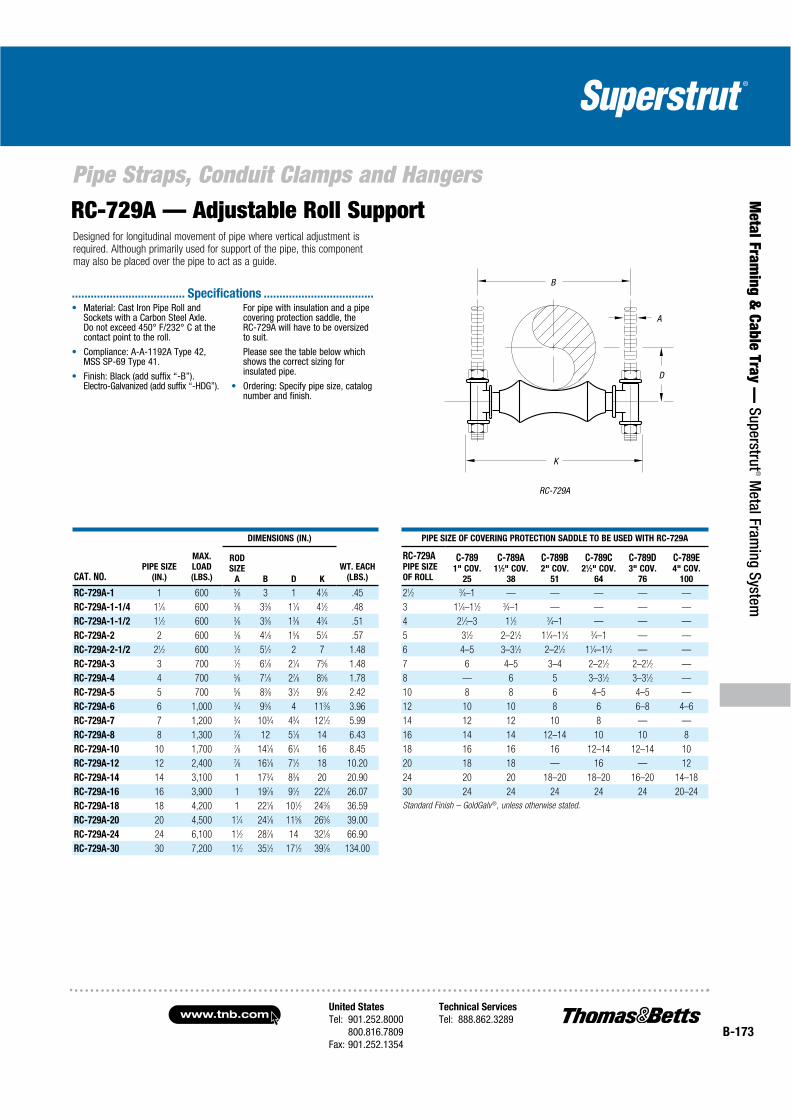
United States
Tel: 901.252.8000800.816.7809
Fax: 901.252.1354
Technical Services
Tel: 888.862.3289www.tnb.com
B-173
Pipe Straps, Conduit Clamps and Hangers
Metal Fram
ing & Cable Tray —
Superstrut® M
etal Framing System
RC-729A
B
A
D
K
RC-729A — Adjustable Roll SupportDesigned for longitudinal movement of pipe where vertical adjustment is required. Although primarily used for support of the pipe, this component may also be placed over the pipe to act as a guide.
Material: Cast Iron Pipe Roll and Sockets with a Carbon Steel Axle. Do not exceed 450° F/232° C at the contact point to the roll.
Compliance: A-A-1192A Type 42, MSS SP-69 Type 41.
Finish: Black (add suffix “-B”). Electro-Galvanized (add suffix “-HDG”).
For pipe with insulation and a pipe covering protection saddle, the RC-729A will have to be oversizedto suit.
Please see the table below which shows the correct sizing for insulated pipe.
Ordering: Specify pipe size, catalog number and finish.
.................................... Specifications ...................................
CAT. NO.PIPE SIZE
(IN.)
MAX.
LOAD
(LBS.)
DIMENSIONS (IN.)
WT. EACH
(LBS.)
PIPE SIZE OF COVERING PROTECTION SADDLE TO BE USED WITH RC-729A
ROD
SIZE
A B D K
RC-729APIPE SIZE
OF ROLL
C-7891" COV.
25
C-789A11⁄2" COV.
38
C-789B2" COV.
51
C-789C21⁄2" COV.
64
C-789D3" COV.
76
C-789E4" COV.
100
RC-729A-1 1 600 3⁄8 3 1 41⁄8 .45 21⁄2 3⁄4–1 — — — — —
RC-729A-1-1/4 11⁄4 600 3⁄8 33⁄8 11⁄4 41⁄2 .48 3 11⁄4–11⁄2 3⁄4–1 — — — —
RC-729A-1-1/2 11⁄2 600 3⁄8 35⁄8 13⁄8 43⁄4 .51 4 21⁄2–3 11⁄2 3⁄4–1 — — —
RC-729A-2 2 600 3⁄8 41⁄8 15⁄8 51⁄4 .57 5 31⁄2 2–21⁄2 11⁄4–11⁄2 3⁄4–1 — —
RC-729A-2-1/2 21⁄2 600 1⁄2 51⁄2 2 7 1.48 6 4–5 3–31⁄2 2–21⁄2 11⁄4–11⁄2 — —
RC-729A-3 3 700 1⁄2 61⁄8 21⁄4 75⁄8 1.48 7 6 4–5 3–4 2–21⁄2 2–21⁄2 —
RC-729A-4 4 700 5⁄8 71⁄8 27⁄8 85⁄8 1.78 8 — 6 5 3–31⁄2 3–31⁄2 —
RC-729A-5 5 700 5⁄8 83⁄8 31⁄2 97⁄8 2.42 10 8 8 6 4–5 4–5 —
RC-729A-6 6 1,000 3⁄4 95⁄8 4 113⁄8 3.96 12 10 10 8 6 6–8 4–6
RC-729A-7 7 1,200 3⁄4 103⁄4 43⁄4 121⁄2 5.99 14 12 12 10 8 — —
RC-729A-8 8 1,300 7⁄8 12 51⁄8 14 6.43 16 14 14 12–14 10 10 8
RC-729A-10 10 1,700 7⁄8 141⁄8 61⁄4 16 8.45 18 16 16 16 12–14 12–14 10
RC-729A-12 12 2,400 7⁄8 161⁄8 71⁄2 18 10.20 20 18 18 — 16 — 12
RC-729A-14 14 3,100 1 173⁄4 83⁄8 20 20.90 24 20 20 18–20 18–20 16–20 14–18
RC-729A-16 16 3,900 1 197⁄8 91⁄2 221⁄8 26.07 30 24 24 24 24 24 20–24
RC-729A-18 18 4,200 1 221⁄8 101⁄2 243⁄8 36.59 Standard Finish – GoldGalv ®, unless otherwise stated.
RC-729A-20 20 4,500 11⁄4 241⁄8 115⁄8 265⁄8 39.00
RC-729A-24 24 6,100 11⁄2 287⁄8 14 321⁄8 66.90
RC-729A-30 30 7,200 11⁄2 351⁄2 171⁄2 397⁄8 134.00
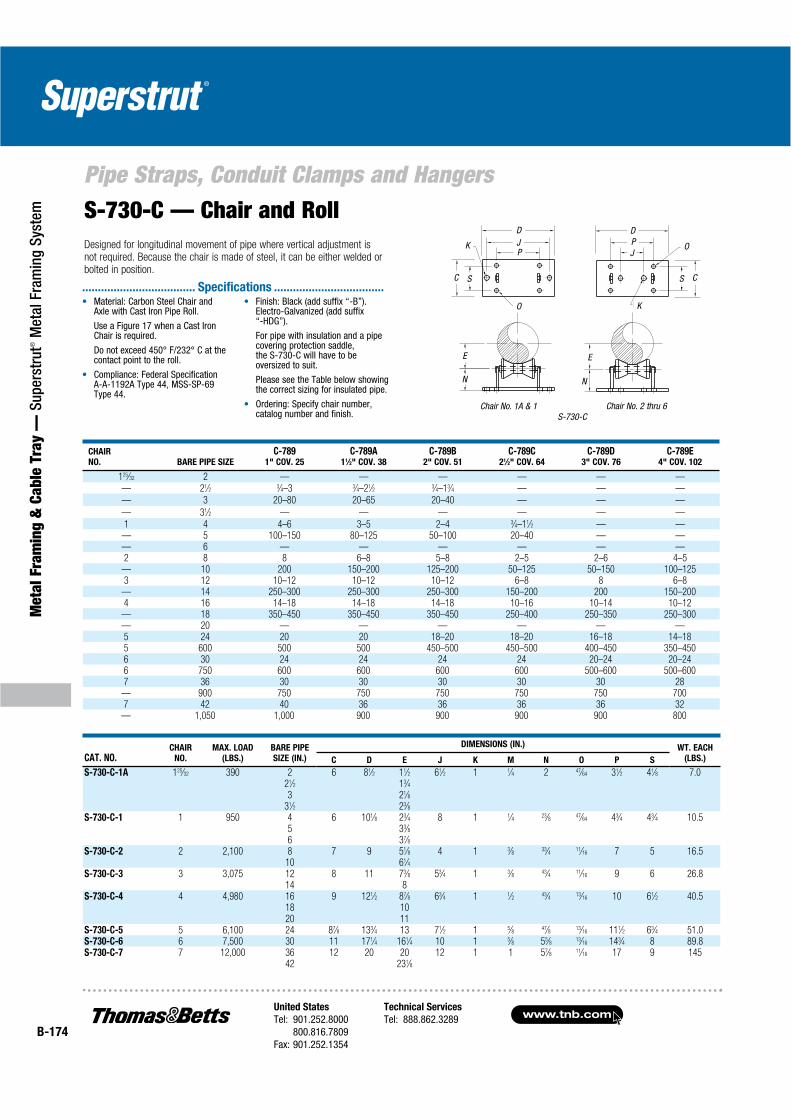
www.tnb.comUnited States
Tel: 901.252.8000800.816.7809
Fax: 901.252.1354
Technical Services
Tel: 888.862.3289B-174
Pipe Straps, Conduit Clamps and Hangers
Met
al F
ram
ing
& C
able
Tra
y —
Sup
erst
rut®
Met
al F
ram
ing
Syst
em
CHAIR
NO. BARE PIPE SIZE
C-7891" COV. 25
C-789A11⁄2" COV. 38
C-789B2" COV. 51
C-789C21⁄2" COV. 64
C-789D3" COV. 76
C-789E4" COV. 102
125⁄32 2 — — — — — —— 21⁄2 3⁄4–3 3⁄4–21⁄2 3⁄4–13⁄4 — — —
— 3 20–80 20–65 20–40 — — —
— 31⁄2 — — — — — —
1 4 4–6 3–5 2–4 3⁄4–11⁄2 — —— 5 100–150 80–125 50–100 20–40 — —— 6 — — — — — —2 8 8 6–8 5–8 2–5 2–6 4–5
— 10 200 150–200 125–200 50–125 50–150 100–1253 12 10–12 10–12 10–12 6–8 8 6–8
— 14 250–300 250–300 250–300 150–200 200 150–2004 16 14–18 14–18 14–18 10–16 10–14 10–12
— 18 350–450 350–450 350–450 250–400 250–350 250–300— 20 — — — — — —5 24 20 20 18–20 18–20 16–18 14–185 600 500 500 450–500 450–500 400–450 350–4506 30 24 24 24 24 20–24 20–246 750 600 600 600 600 500–600 500–6007 36 30 30 30 30 30 28
— 900 750 750 750 750 750 7007 42 40 36 36 36 36 32
— 1,050 1,000 900 900 900 900 800
Material: Carbon Steel Chair and Axle with Cast Iron Pipe Roll.
Use a Figure 17 when a Cast Iron Chair is required.
Do not exceed 450° F/232° C at the contact point to the roll.
Compliance: Federal Specification A-A-1192A Type 44, MSS-SP-69 Type 44.
Finish: Black (add suffix “-B”). Electro-Galvanized (add suffix “-HDG”).
For pipe with insulation and a pipe covering protection saddle, the S-730-C will have to be oversized to suit.
Please see the Table below showing the correct sizing for insulated pipe.
Ordering: Specify chair number, catalog number and finish.
.................................... Specifications ...................................
CAT. NO.CHAIR
NO.
MAX. LOAD
(LBS.)
BARE PIPE
SIZE (IN.)
DIMENSIONS (IN.) WT. EACH
(LBS.)C D E J K M N O P S
S-730-C-1A 125⁄32 390 2 6 81⁄2 11⁄2 61⁄2 1 1⁄4 2 47⁄64 31⁄2 41⁄8 7.021⁄2 13⁄43 21⁄8
31⁄2 23⁄8S-730-C-1 1 950 4 6 101⁄8 23⁄4 8 1 1⁄4 23⁄8 47⁄64 43⁄4 43⁄4 10.5
5 33⁄86 37⁄8
S-730-C-2 2 2,100 8 7 9 51⁄8 4 1 3⁄8 33⁄4 11⁄16 7 5 16.510 61⁄4
S-730-C-3 3 3,075 12 8 11 73⁄8 53⁄4 1 3⁄8 43⁄4 11⁄16 9 6 26.814 8
S-730-C-4 4 4,980 16 9 121⁄2 87⁄8 63⁄4 1 1⁄2 43⁄4 13⁄16 10 61⁄2 40.518 1020 11
S-730-C-5 5 6,100 24 87⁄8 133⁄4 13 71⁄2 1 5⁄8 47⁄8 13⁄16 111⁄2 63⁄4 51.0S-730-C-6 6 7,500 30 11 171⁄4 161⁄4 10 1 5⁄8 55⁄8 13⁄16 143⁄4 8 89.8S-730-C-7 7 12,000 36 12 20 20 12 1 1 57⁄8 11⁄16 17 9 145
42 231⁄8
C S
K
DJP
K
D
JP
CS
O
O
E E
N N
Chair No. 1A & 1 Chair No. 2 thru 6S-730-C
S-730-C — Chair and RollDesigned for longitudinal movement of pipe where vertical adjustment is not required. Because the chair is made of steel, it can be either welded or bolted in position.

United States
Tel: 901.252.8000800.816.7809
Fax: 901.252.1354
Technical Services
Tel: 888.862.3289www.tnb.com
B-175
Pipe Straps, Conduit Clamps and Hangers
Metal Fram
ing & Cable Tray —
Superstrut® M
etal Framing System
C-786 — Adjustable Pipe SupportUsed for support of piping from below without welding to the pipe, and consists of a steel saddle, nipple and pipe reducer. It connects to a threaded pipe standard and base.
Rated loads are for up to 650° F (343° C).
C-786
A
D
E
B
CL
Materials: Reducer is Cast Iron, Pipe saddle and nipple are carbon steel.
Compliance: Federal Specification A-A-1192A Type 39, MSS-SP-69 Type 39.
Finish: Standard Finish – GoldGalv®,Black (add suffix “-B”), Electro-Galvanized (add suffix “-EG”).
Ordering: Specify pipe size, catalog number and finish.
.................................... Specifications ...................................
CAT. NO.PIPE SIZE
(IN.)
MAX. LOAD
(LBS.)
DIMENSIONS (IN.)
WT. EACH
(LBS.)A B D
MIN.
E
MAX.
E
C-786-1-1/2 11⁄2 5,000 21⁄2 11⁄4 11⁄2 8 13 4.75
C-786-2 2 5,000 21⁄2 11⁄2 11⁄2 8 13 4.80
C-786-2-1/2 21⁄2 5,000 21⁄2 17⁄8 11⁄2 8 13 4.90
C-786-3 3 5,000 21⁄2 21⁄8 11⁄2 81⁄4 131⁄4 5.00
C-786-4 4 7,000 3 25⁄8 21⁄2 91⁄8 141⁄8 9.30
C-786-5 5 7,000 3 31⁄4 21⁄2 95⁄8 145⁄8 9.65
C-786-6 6 7,000 3 37⁄8 21⁄2 101⁄4 151⁄4 11.70
C-786-8 8 7,000 3 47⁄8 21⁄2 111⁄4 161⁄4 12.90
C-786-10 10 7,000 3 57⁄8 21⁄2 123⁄8 173⁄8 14.10
C-786-12 12 7,000 3 67⁄8 21⁄2 133⁄8 183⁄8 15.30
C-786-14 14 7,000 4 71⁄2 3 151⁄2 201⁄2 21.70
C-786-16 16 7,000 4 85⁄8 3 165⁄8 215⁄8 25.40
C-786-18 18 7,000 6 95⁄8 4 191⁄8 241⁄8 39.30
C-786-20 20 7,000 6 105⁄8 4 201⁄8 251⁄8 44.90
C-786-24 24 10,000 6 123⁄4 4 221⁄4 271⁄4 54.30
C-786-30 30 10,000 6 153⁄4 4 251⁄4 301⁄4 62.40
C-786-36 36 10,000 6 183⁄4 4 281⁄4 331⁄4 70.20
Standard Finish – GoldGalv ®, unless otherwise stated.
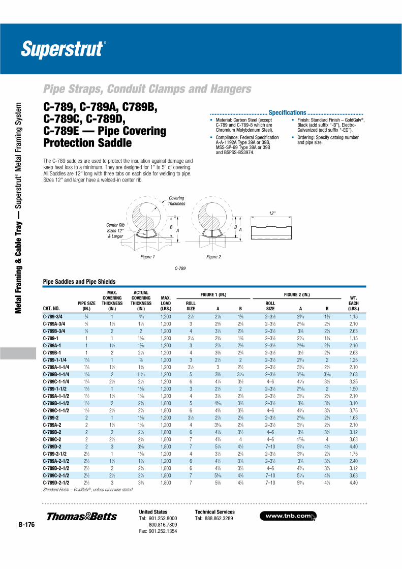
www.tnb.comUnited States
Tel: 901.252.8000800.816.7809
Fax: 901.252.1354
Technical Services
Tel: 888.862.3289B-176
Pipe Straps, Conduit Clamps and Hangers
Met
al F
ram
ing
& C
able
Tra
y —
Sup
erst
rut®
Met
al F
ram
ing
Syst
em
C-789
12"
ABA
B
Figure 2Figure 1
CoveringThickness
Center Rib Sizes 12" & Larger
C-789, C-789A, C789B, C-789C, C-789D, C-789E — Pipe Covering Protection SaddleThe C-789 saddles are used to protect the insulation against damage and keep heat loss to a minimum. They are designed for 1" to 5" of covering. All Saddles are 12" long with three tabs on each side for welding to pipe. Sizes 12" and larger have a welded-in center rib.
Material: Carbon Steel (except C-789 and C-789-8 which are Chromium Molybdenum Steel).
Compliance: Federal Specification A-A-1192A Type 39A or 39B, MSS-SP-69 Type 39A or 39B and BSPSS-BS3974.
Finish: Standard Finish – GoldGalv®,Black (add suffix “-B”), Electro-Galvanized (add suffix “-EG”).
Ordering: Specify catalog number and pipe size.
.................................... Specifications ...................................
Pipe Saddles and Pipe Shields
CAT. NO.PIPE SIZE
(IN.)
MAX.
COVERING
THICKNESS
(IN.)
ACTUAL
COVERING
THICKNESS
(IN.)
MAX.
LOAD
(LBS.)
FIGURE 1 (IN.) FIGURE 2 (IN.)WT.
EACH
(LBS.)
ROLL
SIZE A B
ROLL
SIZE A B
C-789-3/4 3⁄4 1 15⁄16 1,200 21⁄2 21⁄8 15⁄8 2–31⁄2 25⁄16 15⁄8 1.15
C-789A-3/4 3⁄4 11⁄2 11⁄2 1,200 3 25⁄8 21⁄8 2–31⁄2 211⁄16 21⁄4 2.10
C-789B-3/4 3⁄4 2 2 1,200 4 31⁄4 25⁄8 2–31⁄2 33⁄8 25⁄8 2.63
C-789-1 1 1 11⁄16 1,200 21⁄4 23⁄4 13⁄4 2–31⁄2 27⁄16 13⁄4 1.15
C-789A-1 1 11⁄2 19⁄16 1,200 3 27⁄8 23⁄8 2–31⁄2 215⁄16 23⁄8 2.10
C-789B-1 1 2 21⁄8 1,200 4 33⁄8 23⁄4 2–31⁄2 31⁄2 23⁄4 2.63
C-789-1-1/4 11⁄4 1 7⁄8 1,200 3 21⁄2 2 2–31⁄2 29⁄16 2 1.25
C-789A-1-1/4 11⁄4 11⁄2 15⁄8 1,200 31⁄2 3 21⁄2 2–31⁄2 33⁄16 21⁄2 2.10
C-789B-1-1/4 11⁄4 2 115⁄16 1,200 5 35⁄8 31⁄16 2–31⁄2 311⁄16 31⁄16 2.63
C-789C-1-1/4 11⁄4 21⁄2 21⁄2 1,200 6 41⁄4 31⁄2 4–6 41⁄16 31⁄2 3.25
C-789-1-1/2 11⁄2 1 11⁄16 1,200 3 21⁄2 2 2–31⁄2 211⁄16 2 1.50
C-789A-1-1/2 11⁄2 11⁄2 19⁄16 1,200 4 31⁄8 25⁄8 2–31⁄2 35⁄16 25⁄8 2.10
C-789B-1-1/2 11⁄2 2 23⁄8 1,800 5 49⁄16 33⁄8 2–31⁄2 33⁄4 33⁄8 3.10
C-789C-1-1/2 11⁄2 21⁄2 27⁄8 1,800 6 45⁄8 37⁄8 4–6 43⁄16 37⁄8 3.75
C-789-2 2 1 11⁄16 1,200 31⁄2 27⁄8 23⁄8 2–31⁄2 215⁄16 23⁄8 1.63
C-789A-2 2 11⁄2 19⁄16 1,200 4 39⁄16 25⁄8 2–31⁄2 35⁄16 25⁄8 2.10
C-789B-2 2 2 21⁄8 1,800 6 41⁄4 31⁄2 4–6 37⁄8 31⁄2 3.12
C-789C-2 2 21⁄2 25⁄8 1,800 7 43⁄4 4 4–6 413⁄16 4 3.63
C-789D-2 2 3 31⁄16 1,800 7 51⁄4 41⁄2 7–10 55⁄16 41⁄2 4.40
C-789-2-1/2 21⁄2 1 11⁄16 1,200 4 31⁄2 27⁄8 2–31⁄2 39⁄16 27⁄8 1.75
C-789A-2-1/2 21⁄2 11⁄2 17⁄8 1,200 6 41⁄2 33⁄8 2–31⁄2 33⁄4 33⁄8 2.40
C-789B-2-1/2 21⁄2 2 23⁄8 1,800 6 45⁄8 37⁄8 4–6 43⁄16 37⁄8 3.12
C-789C-2-1/2 21⁄2 21⁄2 27⁄8 1,800 7 59⁄16 43⁄8 7–10 51⁄16 43⁄8 3.63
C-789D-2-1/2 21⁄2 3 33⁄8 1,800 7 55⁄8 47⁄8 7–10 59⁄16 47⁄8 4.40
Standard Finish – GoldGalv ®, unless otherwise stated.

United States
Tel: 901.252.8000800.816.7809
Fax: 901.252.1354
Technical Services
Tel: 888.862.3289www.tnb.com
B-177
Pipe Straps, Conduit Clamps and Hangers
Metal Fram
ing & Cable Tray —
Superstrut® M
etal Framing System
Pipe Saddles and Pipe Shields (Continued)
CAT. NO.
PIPE
SIZE
(IN.)
MAX.
COVERING
THICKNESS
(IN.)
ACTUAL
COVERING
THICKNESS
(IN.)
MAX.
LOAD
(LBS.)
FIGURE 1 (IN.) FIGURE 2 (IN.) WT.
EACH
(LBS.)ROLL SIZE A B ROLL SIZE A B
C-789-3 3 1 11⁄16 1,200 4 31⁄2 27⁄8 2–31⁄2 39⁄16 27⁄8 1.75
C-789A-3 3 11⁄2 19⁄16 1,800 6 41⁄2 33⁄4 4–6 41⁄16 33⁄4 2.75
C-789B-3 3 2 21⁄16 1,800 7 43⁄4 4 4–6 49⁄16 4 3.50
C-789C-3 3 21⁄2 29⁄16 1,800 8 53⁄8 45⁄8 7–10 53⁄8 45⁄8 3.93
C-789D-3 3 3 31⁄16 1,800 8 57⁄8 5 7–10 6 5 4.40
C-789-4 4 1 11⁄16 5,000 6 41⁄4 31⁄2 4–6 4 31⁄2 2.13
C-789A-4 4 11⁄2 19⁄16 5,000 7 43⁄4 4 4–6 41⁄16 4 3.00
C-789B-4 4 2 21⁄16 5,000 7 53⁄8 45⁄8 4–6 51⁄8 45⁄8 3.50
C-789C-4 4 21⁄2 29⁄16 5,000 10 6 51⁄8 7–10 57⁄8 51⁄8 3.93
C-789D-4 4 3 31⁄8 5,000 10 65⁄8 53⁄4 7–10 63⁄8 53⁄4 5.00
C-789E-4 4 4 41⁄8 5,000 12 73⁄4 61⁄2 7–10 79⁄16 61⁄2 6.30
C-789-4 4 4 41⁄16 5,000 12 73⁄4 61⁄2 7–10 75⁄8 61⁄2 14.45
C-789-4 4 51⁄2 511⁄16 5,000 16 95⁄8 81⁄4 16 91⁄2 81⁄4 26.40
C-789-5 5 1 11⁄16 1,800 6 47⁄8 41⁄8 4–6 4 41⁄8 2.38
C-789A-5 5 11⁄2 19⁄16 1,800 7 51⁄2 43⁄4 4–6 53⁄16 43⁄4 3.00
C-789B-5 5 2 21⁄16 1,800 8 6 51⁄4 7–10 6 51⁄4 3.62
C-789C-5 5 21⁄2 29⁄16 1,800 10 65⁄8 53⁄4 7–10 67⁄16 53⁄4 4.06
C-789D-5 5 3 31⁄16 1,800 10 71⁄8 61⁄4 7–10 75⁄32 61⁄4 5.00
C-789E-5 5 4 41⁄4 1,800 12 81⁄4 7 7–10 83⁄32 7 6.30
C-789-5 5 4 43⁄16 5,000 12 83⁄8 71⁄8 7–10 81⁄4 71⁄8 14.95
C-789-5 5 51⁄2 511⁄16 5,000 18 103⁄16 83⁄4 18 103⁄4 83⁄4 27.40
C-789-6 6 1 1 1,800 7 53⁄8 45⁄8 4–6 51⁄8 45⁄8 3.85
C-789A-6 6 11⁄2 11⁄2 1,800 8 57⁄8 5 7–10 63⁄16 5 4.75
C-789B-6 6 2 21⁄16 1,800 10 63⁄8 51⁄2 7–10 61⁄2 51⁄2 6.28
C-789C-6 6 21⁄2 29⁄16 1,800 12 7 6 12–15 75⁄8 6 7.09
C-789D-6 6 3 31⁄16 1,800 12 73⁄4 61⁄2 7–10 71⁄2 61⁄2 8.10
C-789E-6 6 4 43⁄16 1,800 12 87⁄8 75⁄8 12–15 813⁄16 75⁄8 10.15
C-789-6 6 4 41⁄8 7,200 12 87⁄8 77⁄8 12–15 87⁄8 77⁄8 16.00
C-789-6 6 51⁄2 55⁄8 7,200 18 119⁄16 10 18 111⁄2 10 27.50
C-789-8 8 1 11⁄16 1,800 10 7 6 7–10 69⁄16 6 5.05
C-789A-8 8 11⁄2 19⁄16 1,800 10 7 6 7–10 73⁄16 6 5.25
C-789B-8 8 2 21⁄16 1,800 12 71⁄2 61⁄2 7–10 711⁄16 61⁄2 7.00
C-789C-8 8 21⁄2 211⁄16 1,800 14 81⁄4 7 12–15 811⁄16 7 7.55
C-789D-8 8 3 33⁄16 1,800 12 87⁄8 75⁄8 12–15 827⁄32 75⁄8 9.90
C-789E-8 8 4 43⁄16 1,800 16 10 83⁄4 12–15 913⁄16 83⁄4 10.13
C-789-8 8 4 43⁄16 7,200 16 10 83⁄4 12–15 97⁄8 83⁄4 16.90
C-789-8 8 51⁄2 59⁄16 7,200 20 1113⁄16 101⁄4 20 113⁄4 101⁄4 34.10
C-789-10 10 1 1 1,800 10 81⁄4 71⁄4 7–10 69⁄16 71⁄4 5.05
C-789A-10 10 11⁄2 15⁄8 1,800 10 81⁄4 71⁄4 7–10 73⁄16 71⁄4 5.25
C-789B-10 10 2 21⁄16 1,800 12 91⁄8 77⁄8 7–10 711⁄16 77⁄8 7.0
C-789C-10 10 21⁄2 21⁄8 1,800 16 95⁄8 81⁄8 16–20 911⁄16 81⁄8 8.75
C-789D-10 10 3 31⁄8 5,000 16 101⁄8 87⁄8 16–20 103⁄8 87⁄8 10.70
C-789E-10 10 4 41⁄8 5,000 18 111⁄8 93⁄4 16–20 111⁄16 93⁄4 13.88
C-789-10 10 4 41⁄16 7,200 18 111⁄8 93⁄4 16–20 111⁄8 93⁄4 17.50
C-789-10 10 51⁄2 59⁄16 7,200 20 131⁄8 111⁄4 20 125⁄8 111⁄4 36.60
C-789-12 12 1 11⁄8 2,500 14 93⁄8 81⁄8 12–15 91⁄4 81⁄8 7.30
C-789A-12 12 11⁄2 15⁄8 5,000 14 93⁄8 81⁄8 12–15 97⁄8 81⁄8 7.35
C-789B-12 12 2 21⁄8 5,000 16 10 85⁄8 16–20 915⁄16 85⁄8 9.20
C-789C-12 12 21⁄2 21⁄8 5,000 18 101⁄2 91⁄8 16–20 109⁄16 91⁄8 10.04
C-789D-12 12 3 31⁄8 5,000 18 111⁄4 93⁄4 16–20 111⁄8 93⁄4 11.00
C-789E-12 12 4 41⁄8 5,000 20 121⁄4 103⁄4 16–20 121⁄16 103⁄4 14.45
C-789-12 12 4 41⁄8 11,000 20 121⁄4 103⁄4 16–20 121⁄8 103⁄4 28.00
C-789-12 12 51⁄2 59⁄16 11,000 24 141⁄4 123⁄8 24 133⁄4 123⁄8 36.60
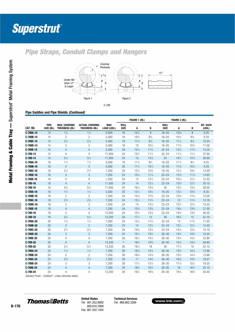
www.tnb.comUnited States
Tel: 901.252.8000800.816.7809
Fax: 901.252.1354
Technical Services
Tel: 888.862.3289B-178
Pipe Straps, Conduit Clamps and Hangers
Met
al F
ram
ing
& C
able
Tra
y —
Sup
erst
rut®
Met
al F
ram
ing
Syst
em
Pipe Saddles and Pipe Shields (Continued)
CAT. NO.PIPE
SIZE (IN.)
MAX. COVERING
THICKNESS (IN.)
ACTUAL COVERING
THICKNESS (IN.)
MAX
LOAD (LBS.)
FIGURE 1 (IN.) FIGURE 2 (IN.)
WT. EACH
(LBS.)
ROLL
SIZE A B
ROLL
SIZE A B
C-789A-14 14 11⁄2 11⁄2 5,000 16 101⁄4 9 16–20 103⁄8 9 8.25
C-789B-14 14 2 2 5,000 18 103⁄4 93⁄8 16–20 103⁄4 93⁄8 9.20
C-789C-14 14 21⁄2 21⁄8 5,000 18 113⁄8 97⁄8 16–20 111⁄4 97⁄8 10.04
C-789D-14 14 3 3 5,000 18 12 101⁄2 16–20 113⁄4 101⁄2 11.00
C-789E-14 14 4 4 5,000 24 131⁄4 113⁄4 22–24 123⁄8 113⁄4 15.50
C-789-14 14 4 4 11,000 24 123⁄4 111⁄4 22–24 117⁄8 111⁄4 27.60
C-789-14 14 51⁄2 51⁄2 11,000 24 15 131⁄8 24 141⁄2 131⁄8 36.60
C-789A-16 16 11⁄2 11⁄2 5,000 18 111⁄8 93⁄4 16–20 111⁄4 93⁄4 8.25
C-789B-16 16 2 2 5,000 20 113⁄4 101⁄4 16–20 115⁄8 101⁄4 9.20
C-789C-16 16 21⁄2 21⁄2 7,200 20 121⁄4 103⁄4 16–20 121⁄4 103⁄4 13.69
C-789D-16 16 3 3 7,200 24 127⁄8 111⁄8 22–24 127⁄8 111⁄8 14.65
C-789E-16 16 4 4 7,200 24 14 121⁄4 22–24 139⁄16 121⁄4 15.50
C-789-16 16 4 4 11,000 24 14 121⁄4 22–24 135⁄8 121⁄4 30.10
C-789-16 16 51⁄2 51⁄2 11,000 30 161⁄5 137⁄8 30 153⁄4 137⁄8 39.00
C-789A-18 18 11⁄2 11⁄2 5,000 20 121⁄4 103⁄4 16–20 121⁄4 103⁄4 9.35
C-789B-18 18 2 2 7,200 24 131⁄8 115⁄8 22–24 123⁄8 115⁄8 12.00
C-789C-18 18 21⁄2 21⁄2 7,200 24 131⁄2 113⁄4 22–24 13 113⁄4 14.19
C-789D-18 18 3 3 7,200 24 14 121⁄4 22–24 131⁄2 121⁄4 15.25
C-789E-18 18 4 4 7,200 24 153⁄8 135⁄8 22–24 145⁄8 135⁄8 21.00
C-789-18 18 4 4 13,200 24 151⁄8 133⁄8 22–24 143⁄8 133⁄8 40.30
C-789-18 18 51⁄2 51⁄2 13,200 30 171⁄3 15 30 167⁄8 15 52.10
C-789A-20 20 11⁄2 11⁄2 7,200 24 131⁄2 113⁄4 22–24 13 113⁄4 11.05
C-789B-20 20 2 2 7,200 24 14 121⁄4 22–24 131⁄2 121⁄4 12.40
C-789C-20 20 21⁄2 21⁄2 7,200 24 145⁄8 127⁄8 22–24 141⁄8 127⁄8 14.19
C-789D-20 20 3 3 7,200 24 151⁄4 133⁄4 26–30 147⁄8 133⁄4 15.25
C-789E-20 20 4 4 7,200 30 161⁄2 141⁄4 26–30 153⁄4 141⁄4 22.80
C-789-20 20 4 4 13,200 7 165⁄8 143⁄8 26–30 157⁄8 143⁄8 44.80
C-789-20 20 51⁄2 51⁄2 13,200 30 181⁄3 16 30 177⁄8 16 52.10
C-789A-24 24 11⁄2 11⁄2 7,200 30 163⁄8 141⁄8 26–30 153⁄4 141⁄8 12.90
C-789B-24 24 2 2 7,200 30 163⁄8 141⁄8 26–30 153⁄4 141⁄8 13.90
C-789C-24 24 21⁄2 21⁄2 7,200 30 17 143⁄4 26–30 165⁄8 143⁄4 18.07
C-789D-24 24 3 3 7,200 30 171⁄2 151⁄4 26–30 171⁄8 151⁄4 19.35
C-789E-24 24 4 4 7,200 30 183⁄4 161⁄2 26–30 18 161⁄2 23.10
C-789-24 24 4 4 13,200 30 187⁄8 165⁄8 26–30 181⁄8 165⁄8 45.40
Standard Finish – GoldGalv®, unless otherwise stated.
C-789
12"
AB
AB
Figure 2Figure 1
CoveringThickness
Center Rib Sizes 12" & Larger
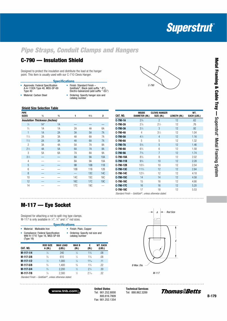
United States
Tel: 901.252.8000800.816.7809
Fax: 901.252.1354
Technical Services
Tel: 888.862.3289www.tnb.com
B-179
Pipe Straps, Conduit Clamps and Hangers
Metal Fram
ing & Cable Tray —
Superstrut® M
etal Framing System
Shield Size Selection Table
PIPE
SIZES 1⁄2 3⁄4 1 11⁄2 2 CAT. NO.INSIDE
DIAMETER (IN.)
CLEVIS HANGER
SIZE (IN.) LENGTH (IN.)
WT.
EACH (LBS.)
Insulation Thickness (Inches) C-790-1A 23⁄8 2 12 .621⁄2 1A* 1A — — — C-790-2A 27⁄8 21⁄2 12 .763⁄4 1A 1A 2A 4A 6A C-790-3A 31⁄2 3 12 .92
1 1A 2A 3A 5A 7A C-790-4A 4 31⁄2 12 1.04
11⁄4 2A 3A 4A 6A 7A C-790-5A 41⁄2 4 12 1.16
11⁄2 2A 3A 4A 6A 7A C-790-6A 5 5 12 1.32
2 3A 4A 5A 7A 8A C-790-7A 55⁄8 5 12 1.46
21⁄2 4A 5A 6A 7A 8A C-790-8A 65⁄8 6 12 1.58
3 5A 6A 7A 8A 9A C-790-9A 75⁄8 7 12 1.74
31⁄2 — — 8A 9A 10A C-790-10A 85⁄8 8 12 2.02
4 — — 8A 9A 10A C-790-11B 95⁄8 10 12 2.28
5 — — 9B 10B 11B C-790-12B 103⁄4 10 12 2.54
6 — — 10B 11B 12B C-790-13C 113⁄4 12 12 2.84
8 — — — 13C 14C C-790-14C 123⁄4 12 12 4.18
10 — — 14C 15C 16C C-790-15C 14 14 12 4.58
12 — — 16C 17C 19C C-790-16C 15 16 12 4.90
14 — — 17C 19C — C-790-17C 16 16 12 5.20
C-790-18C 17 18 12 5.53
Standard Finish – GoldGalv®, unless otherwise stated.
CAT. NO.ROD SIZE
A (IN.)
MAX LOAD
(LBS.)
MAX B
(IN.)
E
(IN.)
WT. EACH
(LBS.)
M-117-1/4 1⁄4 240 1⁄4 13⁄8 .08
M-117-3/8 3⁄8 610 1⁄4 13⁄8 .08
M-117-1/2 1⁄2 1,000 1⁄4 19⁄16 .11
M-117-5/8 5⁄8 1,400 3⁄8 13⁄4 .22
M-117-3/4 3⁄4 2,200 1⁄2 21⁄4 .30
M-117-7/8 7⁄8 2,300 1⁄2 2 7⁄16 .32
Standard Finish – GoldGalv®, unless otherwise stated.
M-117
C-790
A
E
Rod Size
B Max. Dia.
C-790 — Insulation Shield
Designed to protect the insulation and distribute the load at the hanger point. This item is usually used with our C-710 Clevis Hanger.
®
....................................Specifications....................................
M-117 — Eye Socket
Designed for attaching a rod to split ring type clamps. M-117 is only available in 1⁄4", 3⁄8" and 1⁄2" rod sizes.
....................................Specifications....................................

www.tnb.comUnited States
Tel: 901.252.8000800.816.7809
Fax: 901.252.1354
Technical Services
Tel: 888.862.3289B-180
Pipe Straps, Conduit Clamps and Hangers
Met
al F
ram
ing
& C
able
Tra
y —
Sup
erst
rut®
Met
al F
ram
ing
Syst
em Rods and Rod Attachments
Shield Size Selection Table Sizes of CL-710 or C-710 Clevis
CAT. NO.PIPE
SIZES D F 1 1D 2
PIPE
SIZES 1⁄2 3⁄4 1 11⁄2 2
Insulation Thickness (Inches) For Use with Shields Outside of Insulation. Insulation Thickness (Inches)
C-790-1/2 1⁄2 1A* 1A — — — 1⁄2 2 2 — — —
C-790-3/4 3⁄4 1A 1A 2A 4A 6A 3⁄4 2 2 21⁄2 31⁄2 5
C-790-1 1 1A 2A 3A 5A 7A 1 2 21⁄2 3 4 5
C-790-1-1/4 11⁄4 2A 3A 4A 6A 7A 11⁄4 21⁄2 3 3 5 5
C-790-1-1/2 11⁄2 2A 3A 4A 6A 7A 11⁄2 21⁄2 3 31⁄2 5 5
C-790-2 2 3A 4A 5A 7A 8A 2 3 31⁄2 4 5 6
C-790-2-1/2 21⁄2 4A 5A 6A 7A 8A 21⁄2 31⁄2 4 5 5 6
C-790-3 3 5A 6A 7A 8A 9A 3 4 5 5 6 8
C-790-3-1/2 31⁄2 — — 8A 9A 10A 31⁄2 — — 6 8 8
C-790-4 4 — — 8A 9A 10A 4 — — 6 8 8
C-790-5 5 — — 9B 10B 11B 5 — — 8 8 10
C-790-6 6 — — 10B 11B 12B 6 — — 8 10 10
C-790-8 8 — — — 13C 14C 8 — — — 12 12
C-790-10 10 — — 14C 15C 16C 10 — — 12 — —
C-790-12 12 — — 16C 17C 18C
C-790-14 14 — — 17C 18C —
*For Unarco foam, specify X1A
E-151 — Lag Rod
Designed for a vertical rod connection to wood.
CAT. NO.
ROD
SIZE
(IN.)
MAX
LOAD
(LBS.)
MIN. LENGTH (IN.)
WT. EACH (LBS.)
LENGTH — DIMENSION L
MACHINE
B
COACH
C
4
114
6
152
8
203
10
254
12
356
E-151-3/8 3⁄8 390 21⁄2 2 .12 .19 .25 .31 .37
E-151-1/2 1⁄2 640 21⁄2 2 .22 .34 .44 .56 .67
E-151-5/8 5⁄8 750 21⁄2 21⁄2 .35 .53 .70 .87 .59
Standard Finish – GoldGalv®, unless otherwise stated
E-151
A
B C
L
®
.................................... Specifications ...................................

United States
Tel: 901.252.8000800.816.7809
Fax: 901.252.1354
Technical Services
Tel: 888.862.3289www.tnb.com
B-181
Pipe Straps, Conduit Clamps and Hangers
Metal Fram
ing & Cable Tray —
Superstrut® M
etal Framing System
E-157 — Machine Thread Eye RodWelded Eyerods are designed to permit swing in the attachment component due to pipe movement.
E-157
A (IN.) 3⁄8 1⁄2 5⁄8 3⁄4 7⁄8 1 11⁄4 11⁄2 13⁄4 2 21⁄4 21⁄2
B (IN.) 3⁄4 7⁄8 1 11⁄8 11⁄4 13/8 15⁄8 17⁄8 21⁄2 23⁄4 3 31⁄4
Thread
Length D (IN.)
3 3 3 3 4 4 4 6 6 6 6 6
Load at (LBS.)
650° F/343° C
610 1,130 1,810 2,710 3,770 4,960 8,000 11,630 15,700 20,700 27,200 33,500
Load at (LBS.)
750° F/399° C
540 1,010 1,610 2,420 3,360 4,420 7,140 10,370 14,000 18,460 24,260 29,880
Standard Finish – GoldGalv®, unless otherwise stated
AB
D
Specify
1/
®
.................................... Specifications ...................................
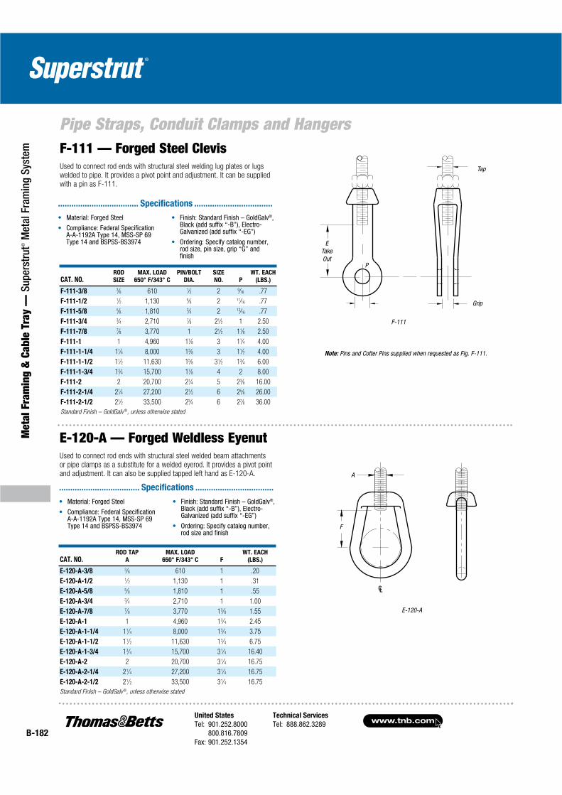
www.tnb.comUnited States
Tel: 901.252.8000800.816.7809
Fax: 901.252.1354
Technical Services
Tel: 888.862.3289B-182
Met
al F
ram
ing
& C
able
Tra
y —
Sup
erst
rut®
Met
al F
ram
ing
Syst
em
Pipe Straps, Conduit Clamps and HangersF-111 — Forged Steel ClevisUsed to connect rod ends with structural steel welding lug plates or lugs welded to pipe. It provides a pivot point and adjustment. It can be supplied with a pin as F-111.
®
.................................... Specifications ...................................
CAT. NO.ROD
SIZE
MAX. LOAD
650° F/343° C
PIN/BOLT
DIA.
SIZE
NO. P
WT. EACH
(LBS.)
F-111-3/8 3⁄8 610 1⁄2 2 9⁄16 .77
F-111-1/2 1⁄2 1,130 5⁄8 2 11⁄16 .77
F-111-5/8 5⁄8 1,810 3⁄4 2 13⁄16 .77
F-111-3/4 3⁄4 2,710 7⁄8 21⁄2 1 2.50
F-111-7/8 7⁄8 3,770 1 21⁄2 11⁄8 2.50
F-111-1 1 4,960 11⁄8 3 11⁄4 4.00
F-111-1-1/4 11⁄4 8,000 13⁄8 3 11⁄2 4.00
F-111-1-1/2 11⁄2 11,630 15⁄8 31⁄2 13⁄4 6.00
F-111-1-3/4 13⁄4 15,700 17⁄8 4 2 8.00
F-111-2 2 20,700 21⁄4 5 23⁄8 16.00
F-111-2-1/4 21⁄4 27,200 21⁄2 6 25⁄8 26.00
F-111-2-1/2 21⁄2 33,500 23⁄4 6 27⁄8 36.00
Standard Finish – GoldGalv ®, unless otherwise stated
E-120-A
F-111
P
Grip
Note: Pins and Cotter Pins supplied when requested as Fig. F-111.
Tap
ETakeOut
A
F
CAT. NO.ROD TAP
A
MAX. LOAD
650° F/343° C F
WT. EACH
(LBS.)
E-120-A-3/8 3⁄8 610 1 .20
E-120-A-1/2 1⁄2 1,130 1 .31
E-120-A-5/8 5⁄8 1,810 1 .55
E-120-A-3/4 3⁄4 2,710 1 1.00
E-120-A-7/8 7⁄8 3,770 13⁄8 1.55
E-120-A-1 1 4,960 13⁄4 2.45
E-120-A-1-1/4 11⁄4 8,000 13⁄4 3.75
E-120-A-1-1/2 11⁄2 11,630 13⁄4 6.75
E-120-A-1-3/4 13⁄4 15,700 31⁄4 16.40
E-120-A-2 2 20,700 31⁄4 16.75
E-120-A-2-1/4 21⁄4 27,200 31⁄4 16.75
E-120-A-2-1/2 21⁄2 33,500 31⁄4 16.75
Standard Finish – GoldGalv®, unless otherwise stated
CL
E-120-A — Forged Weldless EyenutUsed to connect rod ends with structural steel welded beam attachments or pipe clamps as a substitute for a welded eyerod. It provides a pivot point and adjustment. It can also be supplied tapped left hand as E-120-A.
®
.................................... Specifications ...................................
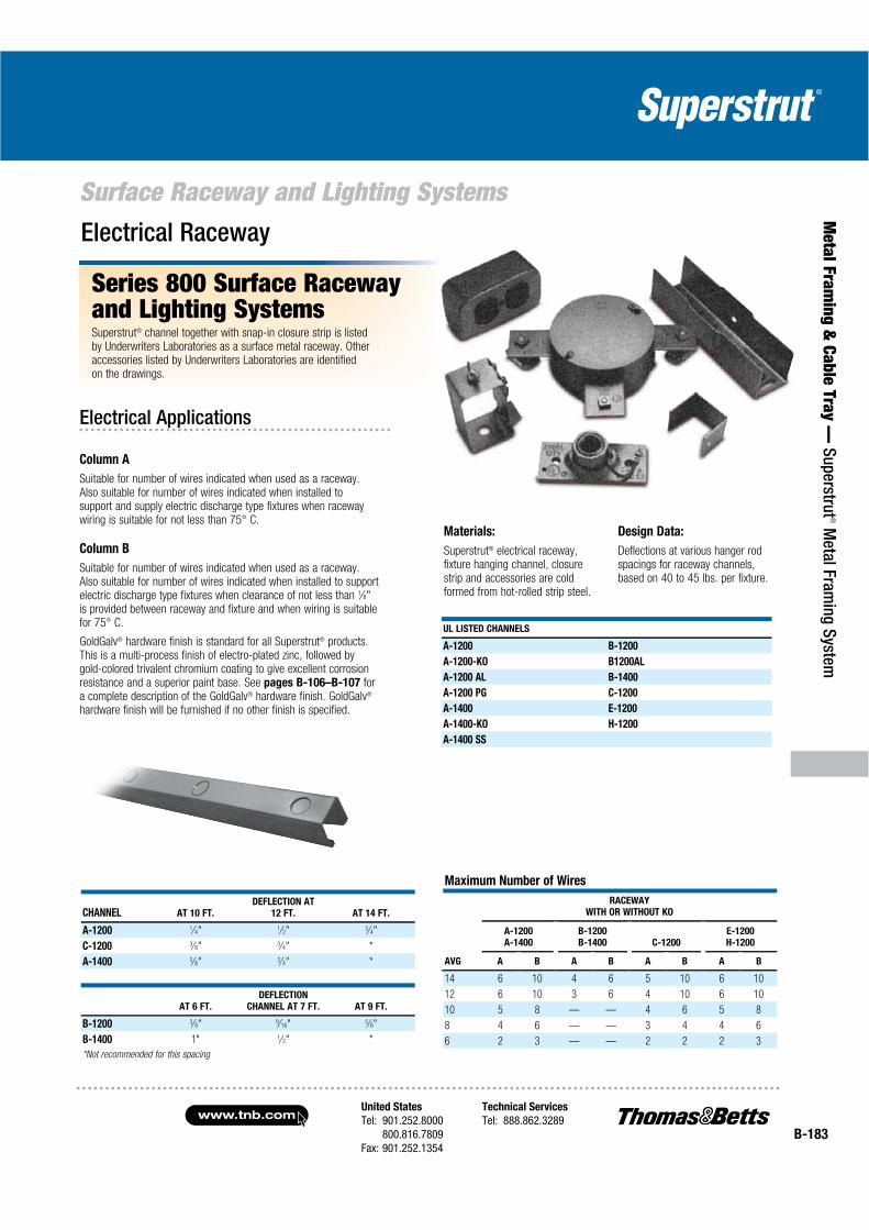
United States
Tel: 901.252.8000800.816.7809
Fax: 901.252.1354
Technical Services
Tel: 888.862.3289www.tnb.com
B-183
Metal Fram
ing & Cable Tray —
Superstrut® M
etal Framing System
Surface Raceway and Lighting Systems
CHANNEL AT 10 FT.
DEFLECTION AT
12 FT. AT 14 FT.
A-1200 1⁄4" 1⁄2" 3⁄4"
C-1200 3⁄8" 3⁄4" *
A-1400 3⁄8" 3⁄4" *
AT 6 FT.
DEFLECTION
CHANNEL AT 7 FT. AT 9 FT.
B-1200 3⁄8" 9⁄16" 5⁄8"
B-1400 1" 1⁄2" *
*Not recommended for this spacing
Maximum Number of Wires
RACEWAY
WITH OR WITHOUT KO
A-1200
A-1400
B-1200
B-1400 C-1200
E-1200
H-1200
AVG A B A B A B A B
14 6 10 4 6 5 10 6 10
12 6 10 3 6 4 10 6 10
10 5 8 — — 4 6 5 8
8 4 6 — — 3 4 4 6
6 2 3 — — 2 2 2 3
UL LISTED CHANNELS
A-1200 B-1200
A-1200-KO B1200AL
A-1200 AL B-1400
A-1200 PG C-1200
A-1400 E-1200
A-1400-KO H-1200
A-1400 SS
Materials:
Superstrut® electrical raceway, fixture hanging channel, closure strip and accessories are cold formed from hot-rolled strip steel.
Design Data:
Deflections at various hanger rod spacings for raceway channels, based on 40 to 45 lbs. per fixture.
Series 800 Surface Raceway and Lighting SystemsSuperstrut® channel together with snap-in closure strip is listed by Underwriters Laboratories as a surface metal raceway. Other accessories listed by Underwriters Laboratories are identified on the drawings.
Electrical Raceway
Electrical Applications
Column A
Suitable for number of wires indicated when used as a raceway. Also suitable for number of wires indicated when installed to support and supply electric discharge type fixtures when raceway wiring is suitable for not less than 75° C.
Column B
Suitable for number of wires indicated when used as a raceway. Also suitable for number of wires indicated when installed to support electric discharge type fixtures when clearance of not less than 1⁄8"is provided between raceway and fixture and when wiring is suitable for 75° C.
GoldGalv® hardware finish is standard for all Superstrut® products. This is a multi-process finish of electro-plated zinc, followed by gold-colored trivalent chromium coating to give excellent corrosion resistance and a superior paint base. See pages B-106–B-107 for a complete description of the GoldGalv® hardware finish. GoldGalv®
hardware finish will be furnished if no other finish is specified.

www.tnb.comUnited States
Tel: 901.252.8000800.816.7809
Fax: 901.252.1354
Technical Services
Tel: 888.862.3289B-184
Met
al F
ram
ing
& C
able
Tra
y —
Sup
erst
rut®
Met
al F
ram
ing
Syst
em
Surface Raceway and Lighting SystemsElectrical Applications (continued)
A-853Page B-186
AB-803Page B-187
AB-885Page B-187
AB-866Page B-187
811Page B-186
804Page B-186
Standard Finish – GoldGalv® brand
822Page B-186
AB-888Page B-187
805Page B-186
A-853Page B-186
H104Page B-117
A-854Page B-186
AB-844Page B-187
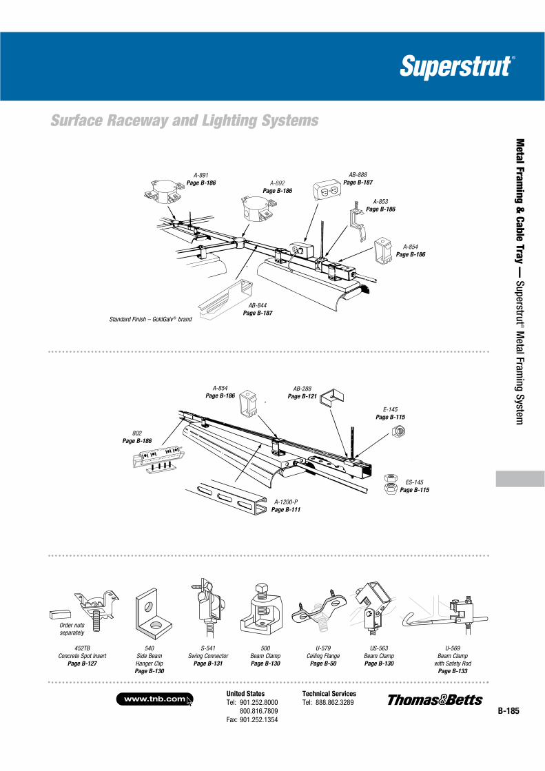
United States
Tel: 901.252.8000800.816.7809
Fax: 901.252.1354
Technical Services
Tel: 888.862.3289www.tnb.com
B-185
Metal Fram
ing & Cable Tray —
Superstrut® M
etal Framing System
Surface Raceway and Lighting Systems
Standard Finish – GoldGalv ® brand
A-891Page B-186
AB-844Page B-187
A-892
Page B-186
AB-888Page B-187
A-853Page B-186
A-854Page B-186
A-854Page B-186
ES-145Page B-115
802Page B-186
A-1200-PPage B-111
AB-288Page B-121
E-145Page B-115
452TBConcrete Spot Insert
Page B-127
Order nuts separately
S-541Swing Connector
Page B-131
500Beam ClampPage B-130
US-563Beam ClampPage B-130
U-569Beam Clamp
with Safety RodPage B-133
U-579Ceiling Flange
Page B-50
540Side Beam Hanger ClipPage B-130
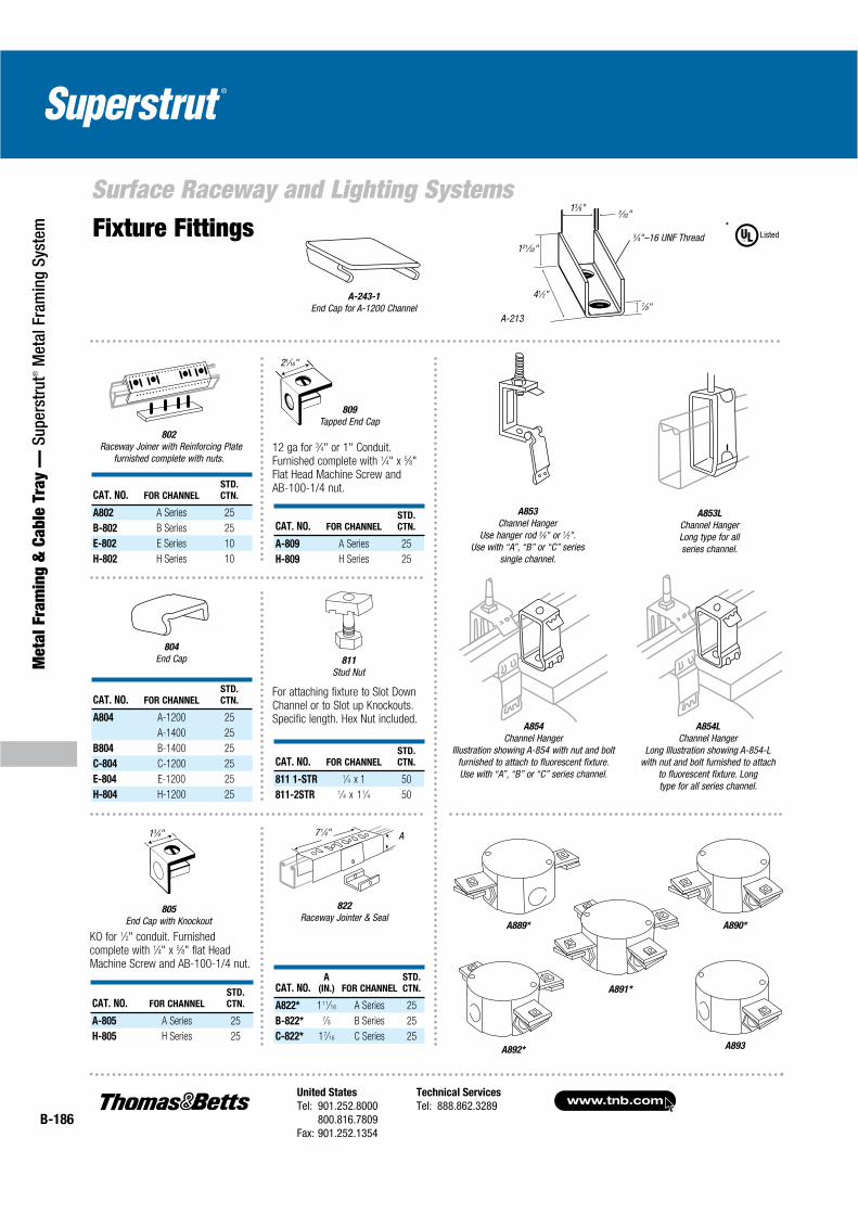
www.tnb.comUnited States
Tel: 901.252.8000800.816.7809
Fax: 901.252.1354
Technical Services
Tel: 888.862.3289B-186
Met
al F
ram
ing
& C
able
Tra
y —
Sup
erst
rut®
Met
al F
ram
ing
Syst
em
Surface Raceway and Lighting Systems
804
End Cap
805
End Cap with Knockout
811
Stud Nut
KO for 1⁄2" conduit. Furnished complete with 1⁄4" x 5⁄8" flat Head Machine Screw and AB-100-1/4 nut.
For attaching fixture to Slot Down Channel or to Slot up Knockouts. Specific length. Hex Nut included.
12 ga for 3⁄4" or 1" Conduit. Furnished complete with 1⁄4" x 5⁄8"Flat Head Machine Screw andAB-100-1/4 nut.
CAT. NO. FOR CHANNEL
STD.
CTN.
A802 A Series 25
B-802 B Series 25
E-802 E Series 10
H-802 H Series 10
802
Raceway Joiner with Reinforcing Plate furnished complete with nuts.
A-243-1
End Cap for A-1200 Channel
Fixture Fittings
809
Tapped End Cap
822
Raceway Jointer & Seal
71⁄4" A
A-213
A889* A890*
A891*
Listed*
3⁄4"–16 UNF Thread121⁄32"
3⁄32"13⁄8"
41⁄2"7⁄8"
A854L
Channel HangerLong Illustration showing A-854-L
with nut and bolt furnished to attach to fluorescent fixture. Longtype for all series channel.
CAT. NO. A
(IN.) FOR CHANNEL
STD.
CTN.
A822* 111⁄16 A Series 25
B-822* 7⁄8 B Series 25
C-822* 17⁄16 C Series 25
A853
Channel HangerUse hanger rod 3⁄8" or 1⁄2".
Use with “A”, “B” or “C” seriessingle channel.
A853L
Channel HangerLong type for all series channel.
A892* A893
A854
Channel HangerIllustration showing A-854 with nut and bolt
furnished to attach to fluorescent fixture. Use with “A”, “B” or “C” series channel.
21⁄16"
13⁄4"
CAT. NO. FOR CHANNEL
STD.
CTN.
A-809 A Series 25
H-809 H Series 25
CAT. NO. FOR CHANNEL
STD.
CTN.
A804 A-1200 25
A-1400 25
B804 B-1400 25
C-804 C-1200 25
E-804 E-1200 25
H-804 H-1200 25
CAT. NO. FOR CHANNEL
STD.
CTN.
811 1-STR 1⁄4 x 1 50
811-2STR 1⁄4 x 11⁄4 50
CAT. NO. FOR CHANNEL
STD.
CTN.
A-805 A Series 25
H-805 H Series 25
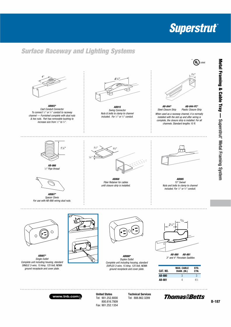
United States
Tel: 901.252.8000800.816.7809
Fax: 901.252.1354
Technical Services
Tel: 888.862.3289www.tnb.com
B-187
Metal Fram
ing & Cable Tray —
Superstrut® M
etal Framing System
Surface Raceway and Lighting Systems
CAT. NO.MAX. CABLE
DIAM. (IN.)
STD.
CTN.
AB-880 3 3
AB-881 4 41⁄2
AB-880 AB-881
3" and 4" Porcelain Saddles
2 1⁄4"
25⁄32
AB803*
Cast Conduit ConnectorTo connect 1⁄2" or 3⁄4" conduit to raceway
channel — Furnished complete with stud nuts& hex nuts. Part has removable bushing to
increase size from 1⁄2" to 3⁄4".
AB815
Swing Connector Nuts & bolts to clamp to channelincluded. For 1⁄2" or 3⁄4" conduit.
4 3⁄4"
AB-844*
Steel Closure StripAB-844-PC*
Plastic Closure Strip
15⁄8"
AB888*
Duplex OutletComplete unit including housing, standard DUPLEX 3-wire, 15 Amp, 125 Volt, NEMA
ground receptacle and cover plate.
AB887*
Single Outlet Complete unit including housing, standard SINGLE 3-wire, 15 Amp, 125 Volt, NEMA
ground receptacle and cover plate.
1⁄32"
13⁄8"11⁄2"
AB-8661⁄2" Pipe thread
AB868
Fiber Retainer for cablesuntil closure strip is installed.
AB867*
Spacer ClevisFor use with AB-866 wiring stud nuts.
AB885
15° SwivelNuts and bolts to clamp to channel
included. For 1⁄2" or 3⁄4" conduit.
4"
When used as a raceway channel, it is normally installed with the slot up and after wiring is
complete, the closure strip is installed. For all channels. Standard lengths 10 ft.
Listed*
1 1⁄8"
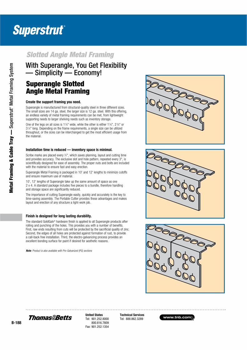
www.tnb.comUnited States
Tel: 901.252.8000800.816.7809
Fax: 901.252.1354
Technical Services
Tel: 888.862.3289B-188
Met
al F
ram
ing
& C
able
Tra
y —
Sup
erst
rut®
Met
al F
ram
ing
Syst
em
Slotted Angle Metal Framing
Superangle Slotted Angle Metal Framing
With Superangle, You Get Flexibility — Simplicity — Economy!
Create the support framing you need.
Superangle is manufactured from structural-quality steel in three different sizes. The small sizes are 14 ga. steel, the larger size is 12 ga. steel. With this offering, an endless variety of metal framing requirements can be met, from lightweight supporting needs to larger shelving needs such as inventory storage.
One of the legs on all sizes is 1 5⁄8" wide, while the other is either 1 5⁄8", 2 3⁄8" or 3 1⁄8" long. Depending on the frame requirements, a single size can be utilized throughout, or the sizes can be interchanged to get the most efficient usage from the material.
Installation time is reduced — inventory space is minimal.
Scribe marks are placed every 3⁄4", which saves planning, layout and cutting time and provides accuracy. The exclusive slot and hole pattern, repeated every 3", is scientifically designed for ease of assembly. The proper nuts and bolts are included with the material to ensure fast and easy erection.
Superangle Metal Framing is packaged in 10' and 12' lengths to minimize cutoffs and ensure maximum use of material.
10', 12' lengths of Superangle take up the same amount of space as one 2 x 4. A standard package includes five pieces to a bundle, therefore handling and storage space are significantly reduced.
The importance of cutting Superangle easily, quickly and accurately is the key to time-saving assembly. The Portable Cutter provides these advantages and makes layout and erection of any structure a light-work job.
Finish is designed for long lasting durability.
The standard GoldGalv® hardware finish is applied to all Superangle products after rolling and punching of the holes. This provides you with a number of benefits. First, raw ends resulting from cuts will be protected by the sacrificial quality of zinc. Second, the edges of all holes are protected against formation of rust, to provide a call-back free installation. Third, the electro-galvanizing process provides an excellent bonding surface for paint if desired for aesthetic reasons.
Note: Product is also available with Pre-Galvanized (PG) sections
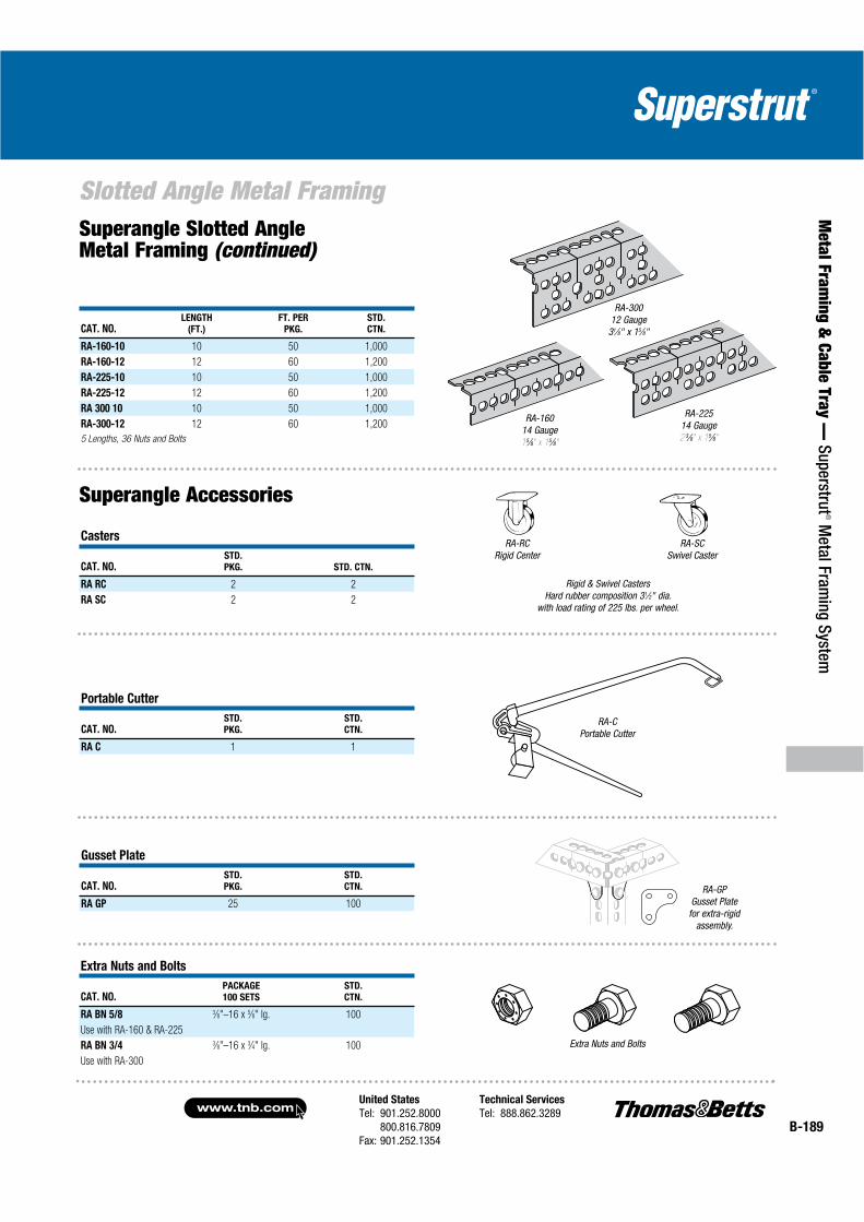
United States
Tel: 901.252.8000800.816.7809
Fax: 901.252.1354
Technical Services
Tel: 888.862.3289www.tnb.com
B-189
Metal Fram
ing & Cable Tray —
Superstrut® M
etal Framing System
Slotted Angle Metal Framing
CAT. NO.LENGTH
(FT.)
FT. PER
PKG.
STD.
CTN.
RA-160-10 10 50 1,000
RA-160-12 12 60 1,200
RA-225-10 10 50 1,000
RA-225-12 12 60 1,200
RA 300 10 10 50 1,000
RA-300-12 12 60 1,200
5 Lengths, 36 Nuts and Bolts
RA-16014 Gauge15⁄8" x 15⁄8"
RA-22514 Gauge2 3⁄8" x 15⁄8"
RA-30012 Gauge
31⁄8" x 15⁄8"
Superangle Slotted Angle Metal Framing (continued)
Superangle Accessories
Casters
CAT. NO.STD.
PKG. STD. CTN.
RA RC 2 2
RA SC 2 2
RA-CPortable Cutter
Portable Cutter
CAT. NO.STD.
PKG.
STD.
CTN.
RA C 1 1
RA-GPGusset Platefor extra-rigid
assembly.
Gusset Plate
CAT. NO.STD.
PKG.
STD.
CTN.
RA GP 25 100
Extra Nuts and Bolts
CAT. NO.PACKAGE
100 SETS
STD.
CTN.
RA BN 5/8 3⁄8"–16 x 5⁄8" lg. 100
Use with RA-160 & RA-225
RA BN 3/4 3⁄8"–16 x 3⁄4" lg. 100
Use with RA-300
Extra Nuts and Bolts
RA-RCRigid Center
RA-SCSwivel Caster
Rigid & Swivel CastersHard rubber composition 31⁄2" dia.
with load rating of 225 lbs. per wheel.
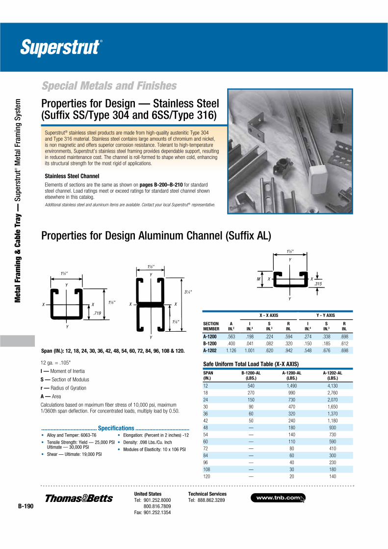
www.tnb.comUnited States
Tel: 901.252.8000800.816.7809
Fax: 901.252.1354
Technical Services
Tel: 888.862.3289B-190
Met
al F
ram
ing
& C
able
Tra
y —
Sup
erst
rut®
Met
al F
ram
ing
Syst
em
Special Metals and Finishes
Superstrut® stainless steel products are made from high-quality austenitic Type 304 and Type 316 material. Stainless steel contains large amounts of chromium and nickel, is non magnetic and offers superior corrosion resistance. Tolerant to high-temperature environments, Superstrut’s stainless steel framing provides dependable support, resultingin reduced maintenance cost. The channel is roll-formed to shape when cold, enhancingits structural strength for the most rigid of applications.
Stainless Steel Channel
Elements of sections are the same as shown on pages B-200–B-210 for standardsteel channel. Load ratings meet or exceed ratings for standard steel channel shown elsewhere in this catalog.
Additional stainless steel and aluminum items are available. Contact your local Superstrut® representative.
Properties for Design — Stainless Steel (Suffix SS/Type 304 and 6SS/Type 316)
Properties for Design Aluminum Channel (Suffix AL)
12 ga. = .105"
I — Moment of Inertia
S — Section of Modulus
r — Radius of Gyration
A — Area
Calculations based on maximum fiber stress of 10,000 psi, maximum 1/360th span deflection. For concentrated loads, multiply load by 0.50.
Y
Y
X X.315
M
15⁄8"
Y
Y
X X
15⁄8"
.719
15⁄8"
Y
Y
X X
31⁄4"
15⁄8"
15⁄8"
Span (IN.): 12, 18, 24, 30, 36, 42, 48, 54, 60, 72, 84, 96, 108 & 120.
SECTION
MEMBER
A
IN.2
X - X AXIS Y - Y AXIS
I
IN.4
S
IN.3
R
IN.
I
IN.4
S
IN.3
R
IN.
A-1200 .563 .198 .224 .594 .274 .338 .698
B-1200 .400 .041 .082 .320 .150 .185 .612
A-1202 1.126 1.001 .620 .942 .548 .676 .698
Safe Uniform Total Load Table (X-X AXIS)
SPAN
(IN.)
B-1200-AL
(LBS.)
A-1200-AL
(LBS.)
A-1202-AL
(LBS.)
12 540 1,490 4,130
18 270 990 2,760
24 150 730 2,070
30 90 470 1,650
36 60 320 1,370
42 50 240 1,180
48 — 180 930
54 — 140 730
60 — 110 590
72 — 80 410
84 — 60 300
96 — 40 230
108 — 30 180
120 — 20 140
Alloy and Temper: 6063-T6
Tensile Strength: Yield — 25,000 PSI Ultimate — 30,000 PSI
Shear — Ultimate: 19,000 PSI
Elongation: (Percent in 2 inches) -12
Density: .098 Lbs./Cu. Inch
Modules of Elasticity: 10 x 106 PSI
.................................... Specifications ...................................

United States
Tel: 901.252.8000800.816.7809
Fax: 901.252.1354
Technical Services
Tel: 888.862.3289www.tnb.com
B-191
Metal Fram
ing & Cable Tray —
Superstrut® M
etal Framing System
Special Metals and FinishesAluminum Products (AL Suffix)
7⁄8"
A-1200-HS_AL
Slots 2" on center.Slot size 9⁄16" x 11⁄8"
15⁄8"7⁄8"
15⁄8"
A Series
A-1200_AL
15⁄8" deep channel and combination
15⁄8"
12 ga.
B-1202_AL
15⁄8"
21⁄2"
17⁄8"
47⁄8"
X201_AL
702_AL
Rigid Conduit Pipe Strap
21⁄4"
15⁄8"
AB201_AL
15⁄8"
12 ga.31⁄4"
A-1202-C_ALA-1202_AL
15⁄8"7⁄8"
13⁄16"
B Series
B-1200_AL

B-192
Special Metals and Finishes
www.tnb.comUnited States
Tel: 901.252.8000800.816.7809
Fax: 901.252.1354
Technical Services
Tel: 888.862.3289
Met
al F
ram
ing
& C
able
Tra
y —
Sup
erst
rut®
Met
al F
ram
ing
Syst
em Stainless Steel ProductsAvailable in:
Type 304 Stainless Steel — SS Suffix
Type 316 Stainless Steel — SS6 Suffix
AB-241 Square Washer
CAT. NO.ROD
SIZE (IN.)
STD.
CTN.
AB-241-1/4 1⁄4 100
AB-241-3/8 3⁄8 100
AB-241-1/2 1⁄2 100
A-1200-HS_SS
A-1200_HS_T316SS
7⁄8"
A-1200_SS
A-1200_T316SS
15⁄8"
15⁄8"
7⁄8"
A Series
A-1202_SS
A-1202-T316SS
A-1202-HS_SS
A-1202-HS_T316SSB-1400-HS_SS
B-1400-HS_T316SS
7⁄8"
15⁄8"7⁄8"
13⁄16"
B Series
12 gaugeB-1200_SS
B-1200_T316SS
14 gaugeB-1400_SS
B-1400_T316SS
E-145
Standard Hex NutE-142
Hex Head Cap ScrewA-100
Regular Spring NutB-100
Short Spring NutAB-100
Springless Nut
E-147
Flat Steel WasherEF-147
Fender Washer
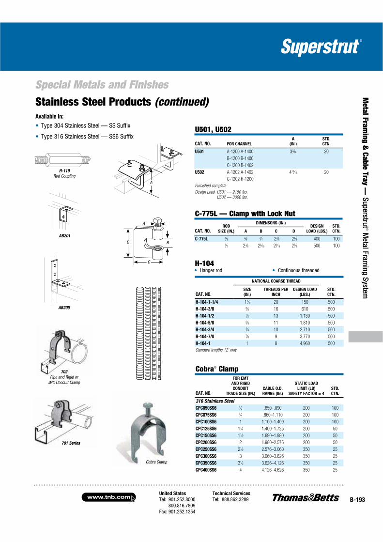
United States
Tel: 901.252.8000800.816.7809
Fax: 901.252.1354
Technical Services
Tel: 888.862.3289www.tnb.comB-193
Special Metals and Finishes
Metal Fram
ing & Cable Tray —
Superstrut® M
etal Framing System
U501, U502
CAT. NO. FOR CHANNEL
A
(IN.)
STD.
CTN.
U501 A-1200 A-1400 33⁄16 20
B-1200 B-1400
C-1200 B-1402
U502 A-1202 A-1402 413⁄16 20
C-1202 H-1200
Furnished complete
Design Load U501 — 2150 lbs.
U502 — 3000 lbs.
C-775L — Clamp with Lock Nut
CAT. NO.ROD
SIZE (IN.)
DIMENSONS (IN.)DESIGN
LOAD (LBS.)
STD.
CTN.A B C D
C-775L 3⁄8 3⁄8 3⁄4 23⁄8 23⁄8 400 1001⁄2 23⁄8 25⁄16 25⁄16 23⁄8 500 100
CAT. NO.
NATIONAL COARSE THREAD
STD.
CTN.
SIZE
(IN.)
THREADS PER
INCH
DESIGN LOAD
(LBS.)
H-104-1-1/4 11⁄4 20 150 500
H-104-3/8 3⁄8 16 610 500
H-104-1/2 1⁄2 13 1,130 500
H-104-5/8 5⁄8 11 1,810 500
H-104-3/4 3⁄4 10 2,710 500
H-104-7/8 7⁄8 9 3,770 500
H-104-1 1 8 4,960 500
Standard lengths 12' only
Hanger rod Continuous threadedH-104
Cobra® Clamp
CAT. NO.
FOR EMT
AND RIGID
CONDUIT
TRADE SIZE (IN.)
CABLE O.D.
RANGE (IN.)
STATIC LOAD
LIMIT (LB)
SAFETY FACTOR = 4
STD.
CTN.
316 Stainless Steel
CPC050SS6 1⁄2 .650–.890 200 100
CPC075SS6 3⁄4 .860–1.110 200 100
CPC100SS6 1 1.100–1.400 200 100
CPC125SS6 11⁄4 1.400–1.725 200 50
CPC150SS6 11⁄2 1.690–1.980 200 50
CPC200SS6 2 1.980–2.576 200 50
CPC250SS6 21⁄2 2.576–3.060 350 25
CPC300SS6 3 3.060–3.626 350 25
CPC350SS6 31⁄2 3.626–4.126 350 25
CPC400SS6 4 4.126–4.626 350 25
AB201
701 Series
702
Pipe and Rigid orIMC Conduit Clamp
H-119
Rod Coupling
AB205
A
A
B
C
D
Cobra Clamp
Stainless Steel Products (continued)Available in:
Type 304 Stainless Steel — SS Suffix
Type 316 Stainless Steel — SS6 Suffix
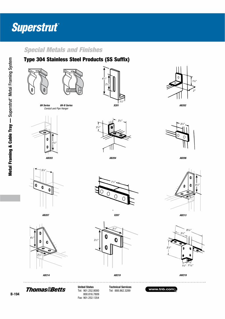
www.tnb.comUnited States
Tel: 901.252.8000800.816.7809
Fax: 901.252.1354
Technical Services
Tel: 888.862.3289B-194
Special Metals and Finishes
Met
al F
ram
ing
& C
able
Tra
y —
Sup
erst
rut®
Met
al F
ram
ing
Syst
em Type 304 Stainless Steel Products (SS Suffix)
6H Series 6H-B Series
Conduit and Pipe Hanger
AB204
X207
AB219 AW219
AB213
X201
AB214
AB207
2"
53⁄8"
95⁄32"
37⁄8"
15⁄8" 121⁄32"
15⁄8"
21⁄4"35⁄8"
35⁄8"
71⁄4"
33⁄4"
AB206
21⁄2"
17⁄8"
41⁄8"
41⁄8"
31⁄2"
41⁄8"3 1⁄2"
3 1⁄2"
31⁄2"
47⁄8"
AB203
AB202
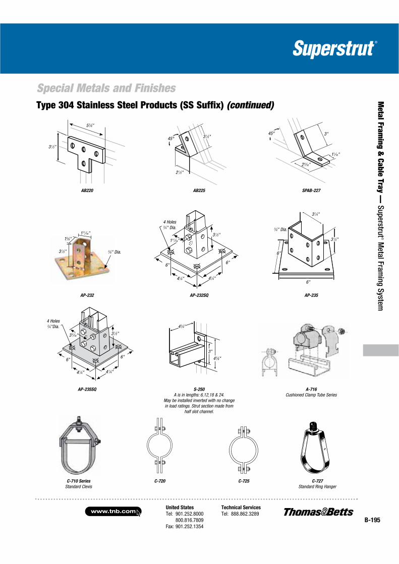
United States
Tel: 901.252.8000800.816.7809
Fax: 901.252.1354
Technical Services
Tel: 888.862.3289www.tnb.com
B-195
Special Metals and Finishes
Metal Fram
ing & Cable Tray —
Superstrut® M
etal Framing System
Type 304 Stainless Steel Products (SS Suffix) (continued)
AP-235
C-727
Standard Ring HangerC-725C-720C-710 Series
Standard Clevis
AP-232
S-250
A is in lengths: 6,12,18 & 24.May be installed inverted with no changein load ratings. Strut section made from
half slot channel.
55⁄8"
45°45°
21⁄2"
31⁄2" 3"
25⁄16"
11⁄16"
41⁄4" 41⁄4"
6"6"
31⁄2"111⁄16"
4 Holes 3⁄4" Dia.
31⁄4"
3⁄4" Dia.
31⁄2"
6"
6"
4 Holes 3⁄4"Dia.
31⁄2"
6"
41⁄4"
43⁄4"
3"
3 5⁄16"
45⁄8"
AB225AB220 SPAB-227
AP-232SQ
A-716
Cushioned Clamp Tube SeriesAP-235SQ
41⁄4"
6"
15⁄8"111⁄16"
31⁄2" 3⁄4" Dia.
31⁄2"
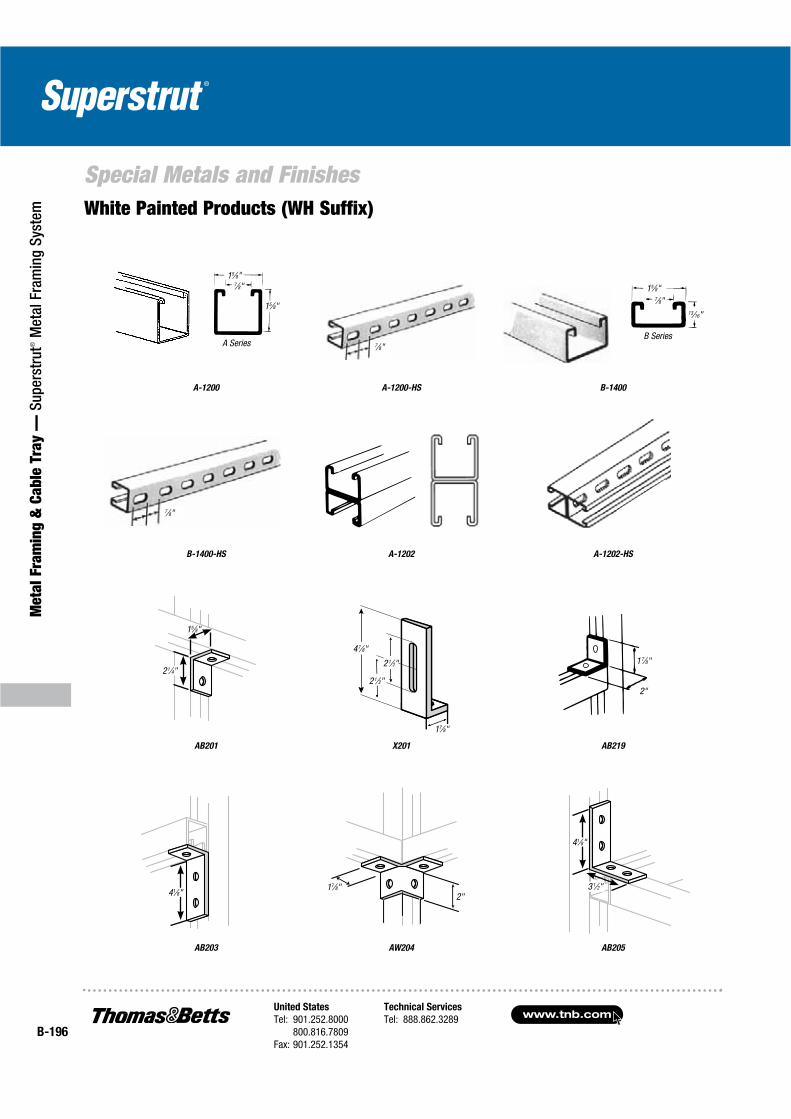
www.tnb.comUnited States
Tel: 901.252.8000800.816.7809
Fax: 901.252.1354
Technical Services
Tel: 888.862.3289B-196
Special Metals and Finishes
Met
al F
ram
ing
& C
able
Tra
y —
Sup
erst
rut®
Met
al F
ram
ing
Syst
em
7⁄8"
15⁄8"
15⁄8"
7⁄8"
A Series
7⁄8"
21⁄2"
21⁄2"
47⁄8"
17⁄8"
2"
17⁄8"
2"17⁄8"
15⁄8"7⁄8"
13⁄16"
B Series
41⁄8"
41⁄8"
31⁄2"
21⁄4"
15⁄8"
White Painted Products (WH Suffix)
AB205AW204
B-1400A-1200 A-1200-HS
X201 AB219AB201
AB203
A-1202-HSB-1400-HS A-1202
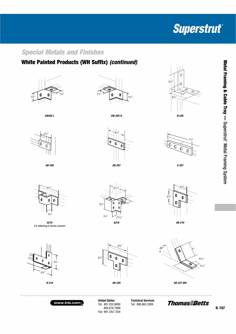
United States
Tel: 901.252.8000800.816.7809
Fax: 901.252.1354
Technical Services
Tel: 888.862.3289www.tnb.com
B-197
Special Metals and Finishes
Metal Fram
ing & Cable Tray —
Superstrut® M
etal Framing System
White Painted Products (WH Suffix) (continued)
AW205 L
A210
For attaching A Series channel
N-219
13⁄4"17⁄8"
5 3⁄8"
15⁄8"
31⁄2"
53⁄8"
31⁄2"
AW-205-R
A218
AB-220
17⁄8"13⁄4"
5 7⁄16"
121⁄32"15⁄8"
3 7⁄8"
53⁄8"
31⁄2"
5 3⁄8"
AB-219
AB-227-WH
7 1⁄4"
45°
11⁄16"
25⁄16"
3"
3 3⁄4"11⁄16"
37⁄8"
1"
31⁄2"
31⁄2"
N-205
AB-206 AB-207 X-207
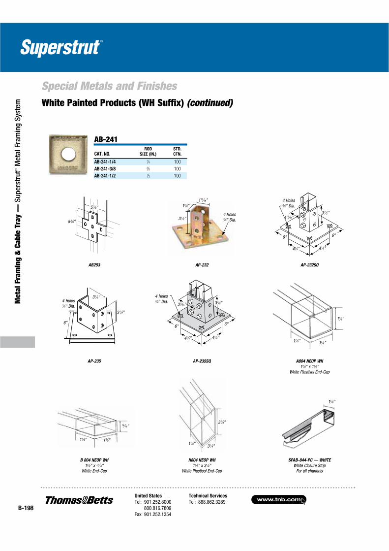
www.tnb.comUnited States
Tel: 901.252.8000800.816.7809
Fax: 901.252.1354
Technical Services
Tel: 888.862.3289B-198
Met
al F
ram
ing
& C
able
Tra
y —
Sup
erst
rut®
Met
al F
ram
ing
Syst
em
Special Metals and Finishes
AB-241
CAT. NO.ROD
SIZE (IN.)
STD.
CTN.
AB-241-1/4 1⁄4 100
AB-241-3/8 3⁄8 100
AB-241-1/2 1⁄2 100
White Painted Products (WH Suffix) (continued)
31⁄4"
31⁄4"11⁄4"
15⁄8"
B 804 NEOP WH
15⁄8" x 13⁄16"White End-Cap
11⁄4" 15⁄8"
13⁄16"
AP-235
3 1⁄4"4 Holes 3⁄4" Dia.
3 1⁄2"
6"
AP-235SQ
SPAB-844-PC — WHITE
White Closure StripFor all channels
AP-232SQAB253
3 1⁄2"
41⁄4" 41⁄4"
6" 6"
4 Holes 3⁄4" Dia.
111⁄16"
41⁄4" 41⁄4"
6" 6"
4 Holes 3⁄4" Dia. 3 5⁄8"3 5⁄16"
11⁄4" 15⁄8"
15⁄8"
5 3⁄8"
5 3⁄8"
A804 NEOP WH
15⁄8" x 15⁄8"White Plastisol End-Cap
H804 NEOP WH
15⁄8" x 31⁄4"White Plastisol End-Cap
AP-232
15⁄8"111⁄16"
3 1⁄2"4 Holes 3⁄4" Dia.

United States
Tel: 901.252.8000800.816.7809
Fax: 901.252.1354
Technical Services
Tel: 888.862.3289www.tnb.com
B-199
Metal Fram
ing & Cable Tray —
Superstrut® M
etal Framing System
Technical Information
Single Channels Double Channels
W
Y Y
Y
Y
ZZH
H
W
X X
X X
Nominal Thickness (IN.)
12 ga. = .105 I — Moment of Inertia
14 ga. = .075 S — Section of Modulus
16 ga. = .060 r — Radius of Gyration
Z — Nominal Axis
A — Area
Design Data — Metal Framing Channel
Elements of Sections
Table 1 — Properties for Design: Single Channel
CAT. NO.H
IN.
W
IN.
A
IN.2
I
IN.4
S
IN.3
R
IN.
X-X AXIS
Z
IN.
I
IN.4
S
IN.3
Y-Y AXIS
R
IN.
A-1200 1.625 1.625 .557 .192 .212 .587 .719 .237 .292 .652
B-1200 .813 1.625 .381 .031 .063 .283 .331 .137 .168 .600
C-1200 1.375 1.625 .500 .121 .155 .492 .595 .205 .252 .640
E-1200 2.438 1.625 .726 .529 .399 .853 1.112 .335 .413 .679
H-1200 3.250 1.625 .897 1.100 .635 1.107 1.507 .436 .536 .697
A-1400 1.625 1.625 .401 .134 .146 .577 .707 .184 .226 .677
B-1400 .813 1.625 .280 .024 .051 .295 .338 .103 .127 .607
Table 1 — Properties for Design: Double Channel
CAT. NO.H
IN.
W
IN.
A
IN.2
I
IN.4
S
IN.3
R
IN.
X-X AXIS
Z
IN.
I
IN.4
S
IN.3
Y-Y AXIS
R
IN.
A-1202 3.250 1.625 1.114 .948 .583 .992 1.625 .474 .584 .652
B-1202 1.626 1.625 .762 .147 .181 .439 .813 .274 .337 .600
C-1202 2.750 1.625 1.000 .595 .433 .772 1.375 .409 .504 .640
E-1202 4.876 1.625 1.450 2.854 1.171 1.402 2.438 .672 .827 .680
H-1202 6.500 1.625 1.794 6.273 1.930 1.870 3.250 .871 1.072 .697
A-1402 3.250 1.625 .801 .668 .411 .913 1.625 .367 .452 .677
B-1402 1.626 1.625 .560 .112 .138 .447 .813 .206 .254 .607
If connections will be subjected to dynamic or seismic loading conditions, contact Thomas & Betts Technical Services for design assistance.
Table 2 — Load Ratings for 1⁄2" Strut Nuts used in Superstrut® Channel
CHANNEL
NO.
SLIP
RESISTANCE
(LBS.)
PULL-OUT STRENGTH
(LBS.)
A-1200 1,500 2,000
C-1200 1,500 2,000
B-1200 1,400 1,400
A-1400 1,000 1,400
B-1400 1,000 1,400
Safety Factor of 3
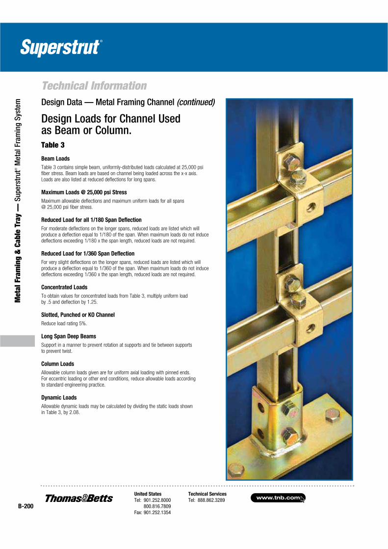
www.tnb.comUnited States
Tel: 901.252.8000800.816.7809
Fax: 901.252.1354
Technical Services
Tel: 888.862.3289B-200
Met
al F
ram
ing
& C
able
Tra
y —
Sup
erst
rut®
Met
al F
ram
ing
Syst
em
Technical InformationDesign Data — Metal Framing Channel (continued)
Design Loads for Channel Used as Beam or Column.Table 3
Beam Loads
Table 3 contains simple beam, uniformly-distributed loads calculated at 25,000 psi fiber stress. Beam loads are based on channel being loaded across the x-x axis. Loads are also listed at reduced deflections for long spans.
Maximum Loads @ 25,000 psi Stress
Maximum allowable deflections and maximum uniform loads for all spans @ 25,000 psi fiber stress.
Reduced Load for all 1/180 Span Deflection
For moderate deflections on the longer spans, reduced loads are listed which will produce a deflection equal to 1/180 of the span. When maximum loads do not induce deflections exceeding 1/180 x the span length, reduced loads are not required.
Reduced Load for 1/360 Span Deflection
For very slight deflections on the longer spans, reduced loads are listed which will produce a deflection equal to 1/360 of the span. When maximum loads do not induce deflections exceeding 1/360 x the span length, reduced loads are not required.
Concentrated Loads
To obtain values for concentrated loads from Table 3, multiply uniform load by .5 and deflection by 1.25.
Slotted, Punched or KO Channel
Reduce load rating 5%.
Long Span Deep Beams
Support in a manner to prevent rotation at supports and tie between supports to prevent twist.
Column Loads
Allowable column loads given are for uniform axial loading with pinned ends. For eccentric loading or other end conditions, reduce allowable loads according to standard engineering practice.
Dynamic Loads
Allowable dynamic loads may be calculated by dividing the static loads shown in Table 3, by 2.08.
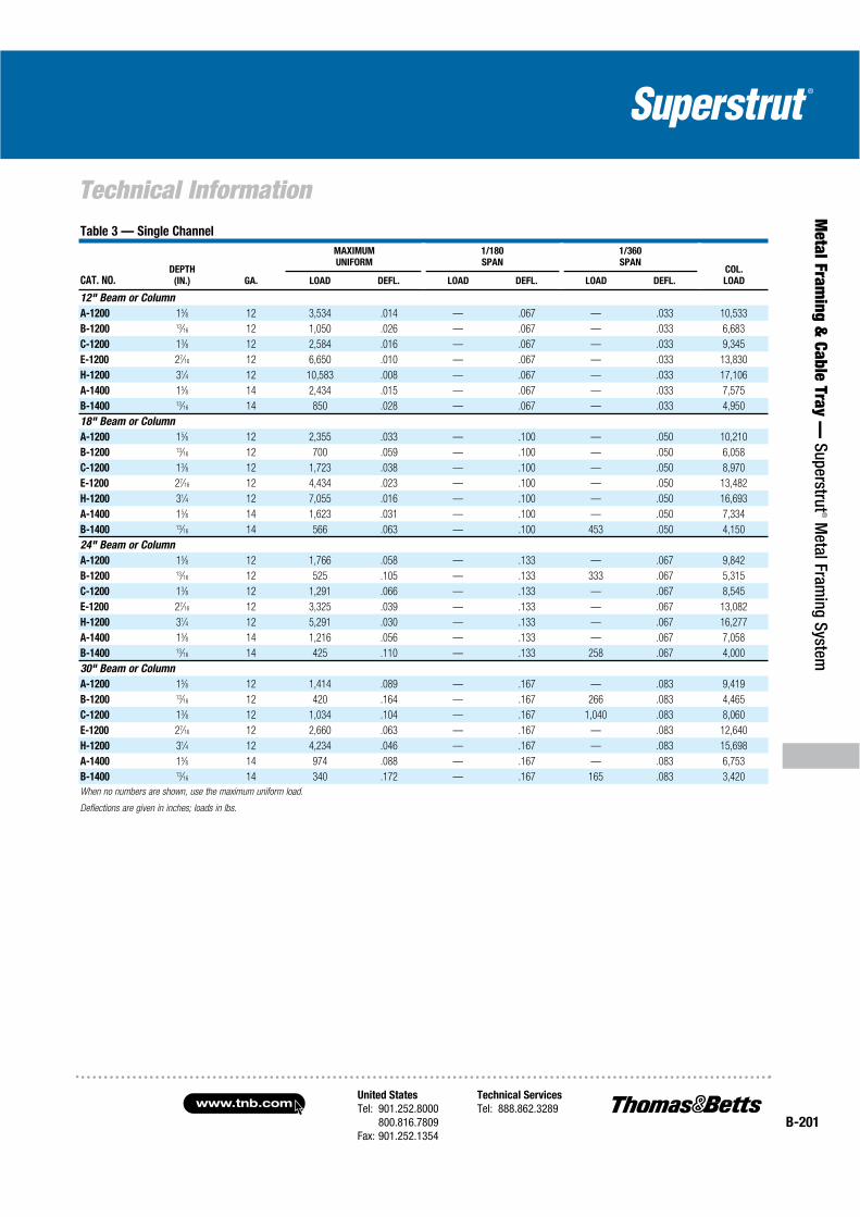
United States
Tel: 901.252.8000800.816.7809
Fax: 901.252.1354
Technical Services
Tel: 888.862.3289www.tnb.com
B-201
Metal Fram
ing & Cable Tray —
Superstrut® M
etal Framing System
Technical InformationTable 3 — Single Channel
CAT. NO.DEPTH
(IN.) GA.
MAXIMUM
UNIFORM
1/180
SPAN
1/360
SPANCOL.
LOADLOAD DEFL. LOAD DEFL. LOAD DEFL.
12" Beam or Column
A-1200 15⁄8 12 3,534 .014 — .067 — .033 10,533
B-1200 13⁄16 12 1,050 .026 — .067 — .033 6,683
C-1200 13⁄8 12 2,584 .016 — .067 — .033 9,345
E-1200 27⁄16 12 6,650 .010 — .067 — .033 13,830
H-1200 31⁄4 12 10,583 .008 — .067 — .033 17,106
A-1400 15⁄8 14 2,434 .015 — .067 — .033 7,575
B-1400 13⁄16 14 850 .028 — .067 — .033 4,950
18" Beam or Column
A-1200 15⁄8 12 2,355 .033 — .100 — .050 10,210
B-1200 13⁄16 12 700 .059 — .100 — .050 6,058
C-1200 13⁄8 12 1,723 .038 — .100 — .050 8,970
E-1200 27⁄16 12 4,434 .023 — .100 — .050 13,482
H-1200 31⁄4 12 7,055 .016 — .100 — .050 16,693
A-1400 15⁄8 14 1,623 .031 — .100 — .050 7,334
B-1400 13⁄16 14 566 .063 — .100 453 .050 4,150
24" Beam or Column
A-1200 15⁄8 12 1,766 .058 — .133 — .067 9,842
B-1200 13⁄16 12 525 .105 — .133 333 .067 5,315
C-1200 13⁄8 12 1,291 .066 — .133 — .067 8,545
E-1200 27⁄16 12 3,325 .039 — .133 — .067 13,082
H-1200 31⁄4 12 5,291 .030 — .133 — .067 16,277
A-1400 15⁄8 14 1,216 .056 — .133 — .067 7,058
B-1400 13⁄16 14 425 .110 — .133 258 .067 4,000
30" Beam or Column
A-1200 15⁄8 12 1,414 .089 — .167 — .083 9,419
B-1200 13⁄16 12 420 .164 — .167 266 .083 4,465
C-1200 13⁄8 12 1,034 .104 — .167 1,040 .083 8,060
E-1200 27⁄16 12 2,660 .063 — .167 — .083 12,640
H-1200 31⁄4 12 4,234 .046 — .167 — .083 15,698
A-1400 15⁄8 14 974 .088 — .167 — .083 6,753
B-1400 13⁄16 14 340 .172 — .167 165 .083 3,420
When no numbers are shown, use the maximum uniform load.
Deflections are given in inches; loads in lbs.
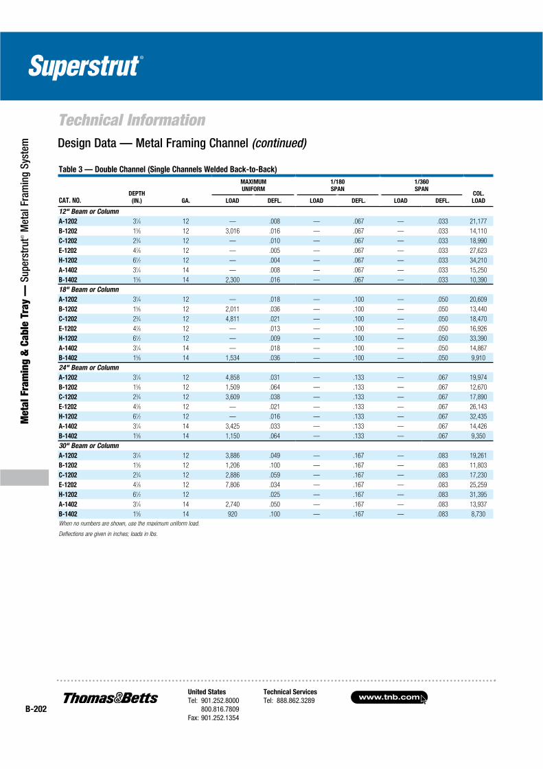
www.tnb.comUnited States
Tel: 901.252.8000800.816.7809
Fax: 901.252.1354
Technical Services
Tel: 888.862.3289B-202
Technical Information
Met
al F
ram
ing
& C
able
Tra
y —
Sup
erst
rut®
Met
al F
ram
ing
Syst
em
Table 3 — Double Channel (Single Channels Welded Back-to-Back)
CAT. NO.DEPTH
(IN.) GA.
MAXIMUM
UNIFORM
1/180
SPAN
1/360
SPANCOL.
LOADLOAD DEFL. LOAD DEFL. LOAD DEFL.
12" Beam or Column
A-1202 31⁄4 12 — .008 — .067 — .033 21,177
B-1202 15⁄8 12 3,016 .016 — .067 — .033 14,110
C-1202 23⁄4 12 — .010 — .067 — .033 18,990
E-1202 47⁄8 12 — .005 — .067 — .033 27,623
H-1202 61⁄2 12 — .004 — .067 — .033 34,210
A-1402 31⁄4 14 — .008 — .067 — .033 15,250
B-1402 15⁄8 14 2,300 .016 — .067 — .033 10,390
18" Beam or Column
A-1202 31⁄4 12 — .018 — .100 — .050 20,609
B-1202 15⁄8 12 2,011 .036 — .100 — .050 13,440
C-1202 23⁄4 12 4,811 .021 — .100 — .050 18,470
E-1202 47⁄8 12 — .013 — .100 — .050 16,926
H-1202 61⁄2 12 — .009 — .100 — .050 33,390
A-1402 31⁄4 14 — .018 — .100 — .050 14,867
B-1402 15⁄8 14 1,534 .036 — .100 — .050 9,910
24" Beam or Column
A-1202 31⁄4 12 4,858 .031 — .133 — .067 19,974
B-1202 15⁄8 12 1,509 .064 — .133 — .067 12,670
C-1202 23⁄4 12 3,609 .038 — .133 — .067 17,890
E-1202 47⁄8 12 — .021 — .133 — .067 26,143
H-1202 61⁄2 12 — .016 — .133 — .067 32,435
A-1402 31⁄4 14 3,425 .033 — .133 — .067 14,426
B-1402 15⁄8 14 1,150 .064 — .133 — .067 9,350
30" Beam or Column
A-1202 31⁄4 12 3,886 .049 — .167 — .083 19,261
B-1202 15⁄8 12 1,206 .100 — .167 — .083 11,803
C-1202 23⁄4 12 2,886 .059 — .167 — .083 17,230
E-1202 47⁄8 12 7,806 .034 — .167 — .083 25,259
H-1202 61⁄2 12 .025 — .167 — .083 31,395
A-1402 31⁄4 14 2,740 .050 — .167 — .083 13,937
B-1402 15⁄8 14 920 .100 — .167 — .083 8,730
When no numbers are shown, use the maximum uniform load.
Deflections are given in inches; loads in lbs.
Design Data — Metal Framing Channel (continued)

United States
Tel: 901.252.8000800.816.7809
Fax: 901.252.1354
Technical Services
Tel: 888.862.3289www.tnb.com
B-203
Technical Information
Metal Fram
ing & Cable Tray —
Superstrut® M
etal Framing System
Table 3 — Single Channel
CAT. NO.DEPTH
(IN.) GA.
MAXIMUM
UNIFORM
1/180
SPAN
1/360
SPANCOL.
LOADLOAD DEFL. LOAD DEFL. LOAD DEFL.
A-1200 15⁄8 12 1,178 .129 — .200 917 .100 8,962
B-1200 13⁄16 12 350 .236 — .200 148 .100 3,498
C-1200 13⁄8 12 861 .149 — .200 578 .100 7,525
E-1200 27⁄16 12 2,216 .088 — .200 — .100 12,160
H-1200 31⁄4 12 3,528 .068 — .200 — .100 15,132
A-1400 15⁄8 14 811 .126 — .200 640 .100 6,416
B-1400 13⁄16 14 284 .248 — .200 115 .100 2,755
42" Beam or Column
A-1200 15⁄8 12 1,010 .175 — .233 674 .117 8,466
B-1200 13⁄16 12 300 .323 217 .233 109 .117 2,579
C-1200 13⁄8 12 738 .203 — .233 425 .117 6,945
E-1200 27⁄16 12 1,900 .120 — .233 — .117 11,698
H-1200 31⁄4 12 3,024 .091 — .233 — .117 14,514
A-1400 15⁄8 14 695 .160 — .233 470 .117 6,051
B-1400 13⁄16 14 243 .336 168 .233 84 .117 2,060
48" Beam or Column
A-1200 15⁄8 12 884 .228 — .267 516 .133 7,943
B-1200 13⁄16 12 263 .420 167 .267 83 .133 1,981
C-1200 13⁄8 12 646 .265 — .267 325 .133 6,325
E-1200 27⁄16 12 1,663 .156 — .267 — .133 11,092
H-1200 31⁄4 12 2,646 .120 — .267 — .133 13,850
A-1400 15⁄8 14 609 .120 — .267 360 .133 5,658
B-1400 13⁄16 14 213 .440 129 .267 64 .133 1,580
54" Beam or Column
A-1200 15⁄8 12 785 .289 — .300 408 .150 7,369
B-1200 13⁄16 12 234 .533 132 .300 66 .150 1,555
C-1200 13⁄8 12 574 .335 — .300 257 .150 5,650
E-1200 27⁄16 12 1,478 .198 — .300 1,123 .150 10,505
H-1200 31⁄4 12 2,351 .151 — .300 — .150 13,150
A-1400 15⁄8 14 541 .286 — .300 284 .150 5,241
B-1400 13⁄16 14 189 .556 102 .300 51 .150 1,250
When no numbers are shown, use the maximum uniform load.
Deflections are given in inches; loads in lbs.

www.tnb.comUnited States
Tel: 901.252.8000800.816.7809
Fax: 901.252.1354
Technical Services
Tel: 888.862.3289B-204
Technical Information
Met
al F
ram
ing
& C
able
Tra
y —
Sup
erst
rut®
Met
al F
ram
ing
Syst
em
Table 3 — Double Channel (Single Channels Welded Back-to-Back)
CAT. NO.DEPTH
(IN.) GA.
MAXIMUM
UNIFORM
1/180
SPAN
1/360
SPANCOL.
LOADLOAD DEFL. LOAD DEFL. LOAD DEFL.
36" Beam or Column
A-1202 31⁄4 12 3,239 .071 — .200 — .100 18,470
B-1202 15⁄8 12 1,005 .144 — .200 702 .100 10,840
C-1202 23⁄4 12 2,400 .085 — .200 — .100 16,500
E-1202 47⁄8 12 6,505 .048 — .200 — .100 24,316
H-1202 61⁄2 12 .036 — .200 — .100 30,265
A-1402 31⁄4 14 2,284 .071 — .200 — .100 13,416
B-1402 15⁄8 14 766 .144 — .200 535 .100 8,050
42" Beam or Column
A-1202 31⁄4 12 2,776 .098 — .233 — .117 17,635
B-1202 15⁄8 12 863 .195 — .233 516 .117 9,790
C-1202 23⁄4 12 2,063 .115 — .233 — .117 15,730
E-1202 47⁄8 12 5,576 .065 — .233 — .117 23,272
H-1202 61⁄2 12 9,190 .049 — .233 — .117 29,025
A-1402 31⁄4 14 1,958 .225 — .233 — .117 12,832
B-1402 15⁄8 14 658 .195 — .233 393 .117 7,300
48" Beam or Column
A-1202 31⁄4 12 2,429 .128 — .267 — .133 16,730
B-1202 15⁄8 12 754 .255 — .267 395 .133 8,640
C-1202 23⁄4 12 1,804 .151 — .267 — .133 14,890
E-1202 47⁄8 12 4,879 .085 — .267 — .133 22,170
H-1202 61⁄2 12 8,041 .064 — .267 — .133 27,700
A-1402 31⁄4 14 1,713 .128 — .267 — .133 12,223
B-1402 15⁄8 14 575 .255 — .267 301 .133 6,480
54" Beam or Column
A-1202 31⁄4 12 2,159 .161 — .300 — .150 15,763
B-1202 15⁄8 12 670 .323 — .300 312 .150 7,405
C-1202 23⁄4 12 1,604 .190 — .300 1,263 .150 13,990
E-1202 47⁄8 12 4,338 .108 — .300 — .150 20,980
H-1202 61⁄2 12 7,149 .081 — .300 — .150 16,280
A-1402 31⁄4 14 1,523 .161 — .300 — .150 11,566
B-1402 15⁄8 14 511 .323 — .300 238 .150 5,580
When no numbers are shown, use the maximum uniform load.
Deflections are given in inches; loads in lbs.
Design Data — Metal Framing Channel (continued)
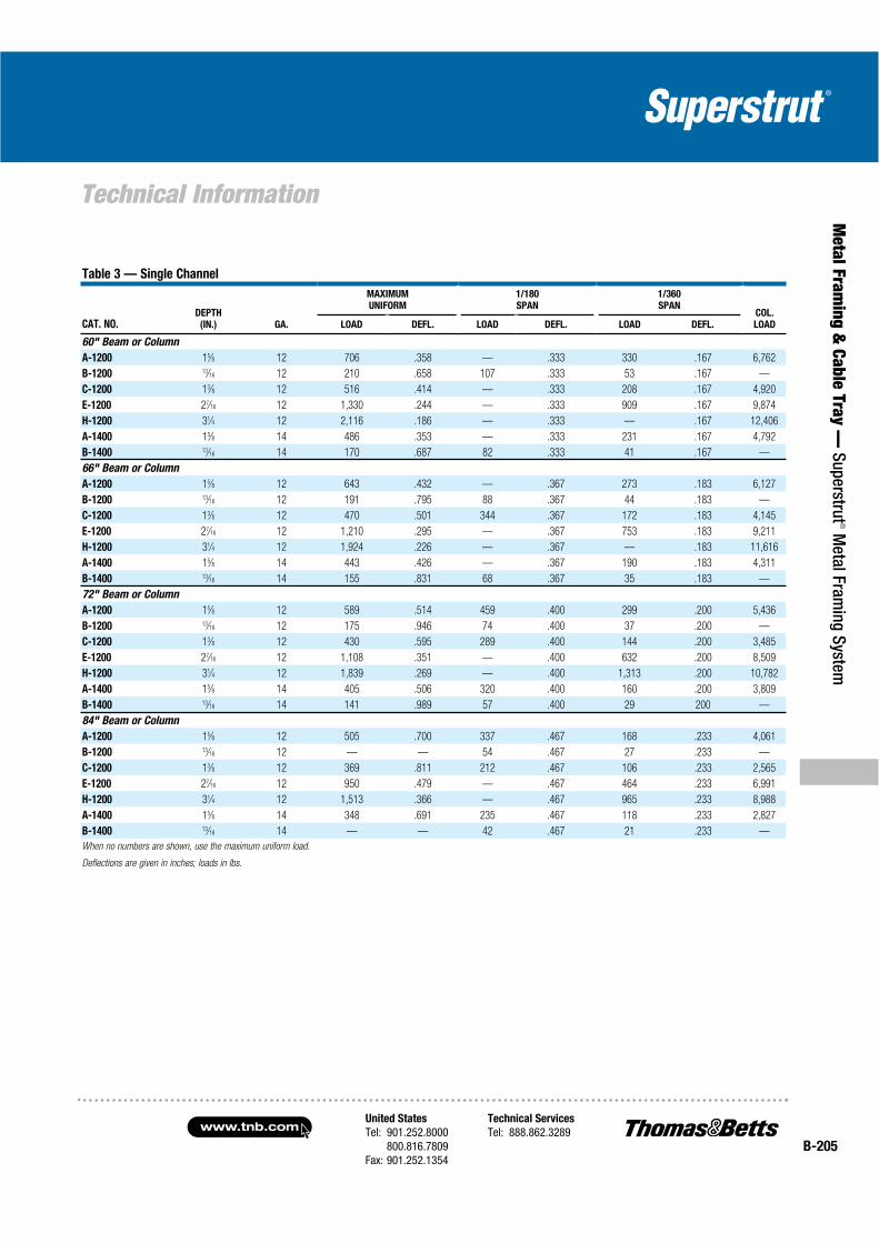
United States
Tel: 901.252.8000800.816.7809
Fax: 901.252.1354
Technical Services
Tel: 888.862.3289www.tnb.com
B-205
Technical Information
Metal Fram
ing & Cable Tray —
Superstrut® M
etal Framing System
Table 3 — Single Channel
CAT. NO.DEPTH
(IN.) GA.
MAXIMUM
UNIFORM
1/180
SPAN
1/360
SPANCOL.
LOADLOAD DEFL. LOAD DEFL. LOAD DEFL.
60" Beam or Column
A-1200 15⁄8 12 706 .358 — .333 330 .167 6,762
B-1200 13⁄16 12 210 .658 107 .333 53 .167 —
C-1200 13⁄8 12 516 .414 — .333 208 .167 4,920
E-1200 27⁄16 12 1,330 .244 — .333 909 .167 9,874
H-1200 31⁄4 12 2,116 .186 — .333 — .167 12,406
A-1400 15⁄8 14 486 .353 — .333 231 .167 4,792
B-1400 13⁄16 14 170 .687 82 .333 41 .167 —
66" Beam or Column
A-1200 15⁄8 12 643 .432 — .367 273 .183 6,127
B-1200 13⁄16 12 191 .795 88 .367 44 .183 —
C-1200 13⁄8 12 470 .501 344 .367 172 .183 4,145
E-1200 27⁄16 12 1,210 .295 — .367 753 .183 9,211
H-1200 31⁄4 12 1,924 .226 — .367 — .183 11,616
A-1400 15⁄8 14 443 .426 — .367 190 .183 4,311
B-1400 13⁄16 14 155 .831 68 .367 35 .183 —
72" Beam or Column
A-1200 15⁄8 12 589 .514 459 .400 299 .200 5,436
B-1200 13⁄16 12 175 .946 74 .400 37 .200 —
C-1200 13⁄8 12 430 .595 289 .400 144 .200 3,485
E-1200 27⁄16 12 1,108 .351 — .400 632 .200 8,509
H-1200 31⁄4 12 1,839 .269 — .400 1,313 .200 10,782
A-1400 15⁄8 14 405 .506 320 .400 160 .200 3,809
B-1400 13⁄16 14 141 .989 57 .400 29 200 —
84" Beam or Column
A-1200 15⁄8 12 505 .700 337 .467 168 .233 4,061
B-1200 13⁄16 12 — — 54 .467 27 .233 —
C-1200 13⁄8 12 369 .811 212 .467 106 .233 2,565
E-1200 27⁄16 12 950 .479 — .467 464 .233 6,991
H-1200 31⁄4 12 1,513 .366 — .467 965 .233 8,988
A-1400 15⁄8 14 348 .691 235 .467 118 .233 2,827
B-1400 13⁄16 14 — — 42 .467 21 .233 —
When no numbers are shown, use the maximum uniform load.
Deflections are given in inches; loads in lbs.

www.tnb.comUnited States
Tel: 901.252.8000800.816.7809
Fax: 901.252.1354
Technical Services
Tel: 888.862.3289B-206
Technical Information
Met
al F
ram
ing
& C
able
Tra
y —
Sup
erst
rut®
Met
al F
ram
ing
Syst
em
Table 3 — Double Channel (Single Channels Welded Back-to-Back)
CAT. NO.DEPTH
(IN.) GA.
MAXIMUM
UNIFORM
1/180
SPAN
1/360
SPANCOL.
LOADLOAD DEFL. LOAD DEFL. LOAD DEFL.
60" Beam or Column
A-1202 31⁄4 12 1,944 .199 — .333 — .167 14,738
B-1202 15⁄8 12 604 .398 — .333 253 .167 6,100
C-1202 23⁄4 12 1,444 .235 — .333 1,023 .167 13,050
E-1202 47⁄8 12 3,904 .133 — .333 — .167 19,734
H-1202 61⁄2 12 6,434 .100 — .333 — .167 24,810
A-1402 31⁄4 14 1,370 .199 — .333 — .167 10,878
B-1402 15⁄8 14 460 .399 — .333 193 .167 4,640
66" Beam or Column
A-1202 31⁄4 12 1,766 .240 — .367 1,347 .183 13,646
B-1202 15⁄8 12 549 .481 418 .367 209 .183 5,055
C-1202 23⁄4 12 1,313 .285 — .367 846 .183 12,030
E-1202 47⁄8 12 3,549 .180 — .367 — .183 18,415
H-1202 61⁄2 12 5,849 .120 — .367 — .183 23,230
A-1402 31⁄4 14 1,245 .241 — .367 949 .183 10,133
B-1402 15⁄8 14 419 .483 318 .367 159 .183 3,840
72" Beam or Column
A-1202 31⁄4 12 1,620 .286 — .400 1,132 .200 12,500
B-1202 15⁄8 12 503 .574 351 .400 176 .200 4,230
C-1202 23⁄4 12 1,203 .339 — .400 710 .200 10,980
E-1202 47⁄8 12 3,253 .191 — .400 — .200 17,023
H-1202 61⁄2 12 5,361 .143 — .400 — .200 21,560
A-1402 31⁄4 14 1,141 .286 — .400 798 .200 9,340
B-1402 15⁄8 14 384 .574 267 .400 134 .200 3,220
84" Beam or Column
A-1202 31⁄4 12 1,388 .390 — .467 832 .233 9,992
B-1202 15⁄8 12 431 .780 258 .467 129 .233 3,100
C-1202 23⁄4 12 1,031 .461 — .467 522 .233 8,670
E-1202 47⁄8 12 2,788 .260 — .467 — .233 13,993
H-1202 61⁄2 12 4,595 .195 — .467 — .233 17,975
A-1402 31⁄4 14 979 .390 — .467 586 .233 7,682
B-1402 15⁄8 14 329 .781 197 .467 98 .233 2,370
When no numbers are shown, use the maximum uniform load.
Deflections are given in inches; loads in lbs.
Design Data — Metal Framing Channel (continued)

United States
Tel: 901.252.8000800.816.7809
Fax: 901.252.1354
Technical Services
Tel: 888.862.3289www.tnb.com
B-207
Technical Information
Metal Fram
ing & Cable Tray —
Superstrut® M
etal Framing System
Table 3 — Single Channel
CAT. NO.DEPTH
(IN.) GA.
MAXIMUM
UNIFORM
1/180
SPAN
1/360
SPANCOL.
LOADLOAD DEFL. LOAD DEFL. LOAD DEFL.
96" Beam or Column
A-1200 15⁄8 12 441 .914 258 .533 129 .267 3,108
B-1200 13⁄16 12 — — 42 .533 21 .267 —
C-1200 13⁄8 12 323 1.059 163 .533 81 .267 1,960
E-1200 27⁄16 12 831 .730 — .533 355 .267 5,423
H-1200 31⁄4 12 1,323 .478 — .533 739 .267 7,059
A-1400 15⁄8 14 304 .903 180 .533 90 .267 2,615
B-1400 13⁄16 14 — — 32 .533 16 .267 —
108" Beam or Column
A-1200 15⁄8 12 393 1.156 204 .600 102 .300 2,456
B-1200 13⁄16 12 — — 33 .600 16 .300 —
C-1200 13⁄8 12 288 1.350 128 .600 64 .300 —
E-1200 27⁄16 12 739 .790 561 .600 281 .300 4,291
H-1200 31⁄4 12 1,176 .605 — .600 584 .300 5,579
A-1400 15⁄8 14 270 1.141 142 .600 71 .300 1,708
B-1400 13⁄16 14 — — 25 .600 13 .300 —
120" Beam or Column
A-1200 15⁄8 12 354 1.425 165 .667 83 .333 —
B-1200 13⁄16 12 — — 27 .667 13 .333 —
C-1200 13⁄8 12 259 1.663 104 .667 52 .333 —
E-1200 27⁄16 12 665 .976 455 .667 227 .333 3,478
H-1200 31⁄4 12 1,059 .746 — .667 473 .333 4,521
A-1400 15⁄8 14 244 1.413 114 .667 57 .333 —
B-1400 13⁄16 14 — — 21 .667 10 .333 —
144" Beam or Column
A-1200 15⁄8 12 — — 115 .800 57 .400 —
C-1200 13⁄8 12 — — 72 .800 36 .400 —
E-1200 27⁄16 12 554 1.400 315 .800 158 .400 —
H-1200 31⁄4 12 883 1.075 657 .800 328 .400 —
A-1400 15⁄8 14 — — 80 .800 40 .400 —
When no numbers are shown, use the maximum uniform load.
Deflections are given in inches; loads in lbs.
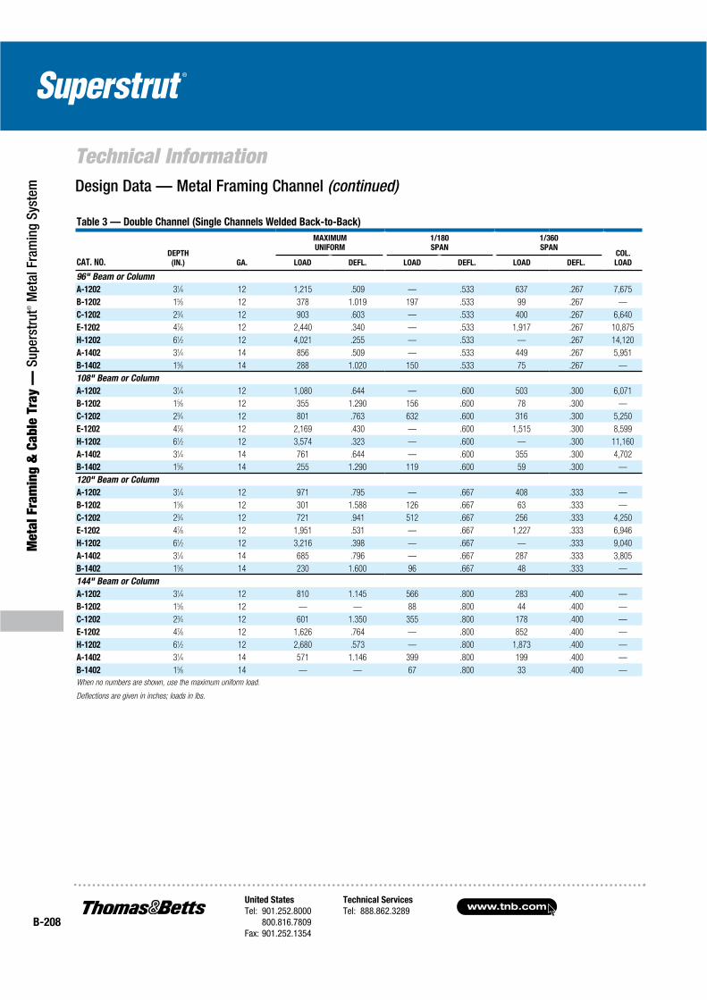
www.tnb.comUnited States
Tel: 901.252.8000800.816.7809
Fax: 901.252.1354
Technical Services
Tel: 888.862.3289B-208
Technical Information
Met
al F
ram
ing
& C
able
Tra
y —
Sup
erst
rut®
Met
al F
ram
ing
Syst
em
Table 3 — Double Channel (Single Channels Welded Back-to-Back)
CAT. NO.DEPTH
(IN.) GA.
MAXIMUM
UNIFORM
1/180
SPAN
1/360
SPANCOL.
LOADLOAD DEFL. LOAD DEFL. LOAD DEFL.
96" Beam or Column
A-1202 31⁄4 12 1,215 .509 — .533 637 .267 7,675
B-1202 15⁄8 12 378 1.019 197 .533 99 .267 —
C-1202 23⁄4 12 903 .603 — .533 400 .267 6,640
E-1202 47⁄8 12 2,440 .340 — .533 1,917 .267 10,875
H-1202 61⁄2 12 4,021 .255 — .533 — .267 14,120
A-1402 31⁄4 14 856 .509 — .533 449 .267 5,951
B-1402 15⁄8 14 288 1.020 150 .533 75 .267 —
108" Beam or Column
A-1202 31⁄4 12 1,080 .644 — .600 503 .300 6,071
B-1202 15⁄8 12 355 1.290 156 .600 78 .300 —
C-1202 23⁄4 12 801 .763 632 .600 316 .300 5,250
E-1202 47⁄8 12 2,169 .430 — .600 1,515 .300 8,599
H-1202 61⁄2 12 3,574 .323 — .600 — .300 11,160
A-1402 31⁄4 14 761 .644 — .600 355 .300 4,702
B-1402 15⁄8 14 255 1.290 119 .600 59 .300 —
120" Beam or Column
A-1202 31⁄4 12 971 .795 — .667 408 .333 —
B-1202 15⁄8 12 301 1.588 126 .667 63 .333 —
C-1202 23⁄4 12 721 .941 512 .667 256 .333 4,250
E-1202 47⁄8 12 1,951 .531 — .667 1,227 .333 6,946
H-1202 61⁄2 12 3,216 .398 — .667 — .333 9,040
A-1402 31⁄4 14 685 .796 — .667 287 .333 3,805
B-1402 15⁄8 14 230 1.600 96 .667 48 .333 —
144" Beam or Column
A-1202 31⁄4 12 810 1.145 566 .800 283 .400 —
B-1202 15⁄8 12 — — 88 .800 44 .400 —
C-1202 23⁄4 12 601 1.350 355 .800 178 .400 —
E-1202 47⁄8 12 1,626 .764 — .800 852 .400 —
H-1202 61⁄2 12 2,680 .573 — .800 1,873 .400 —
A-1402 31⁄4 14 571 1.146 399 .800 199 .400 —
B-1402 15⁄8 14 — — 67 .800 33 .400 —
When no numbers are shown, use the maximum uniform load.
Deflections are given in inches; loads in lbs.
Design Data — Metal Framing Channel (continued)
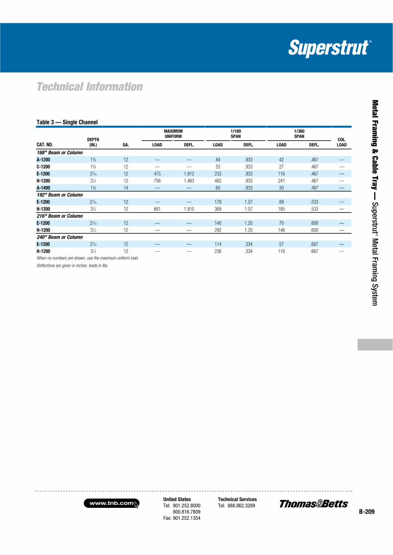
United States
Tel: 901.252.8000800.816.7809
Fax: 901.252.1354
Technical Services
Tel: 888.862.3289www.tnb.com
B-209
Technical Information
Metal Fram
ing & Cable Tray —
Superstrut® M
etal Framing System
Table 3 — Single Channel
CAT. NO.DEPTH
(IN.) GA.
MAXIMUM
UNIFORM
1/180
SPAN
1/360
SPANCOL.
LOADLOAD DEFL. LOAD DEFL. LOAD DEFL.
168" Beam or Column
A-1200 15⁄8 12 — — 84 .933 42 .467 —
C-1200 13⁄8 12 — — 53 .933 27 .467 —
E-1200 27⁄16 12 475 1.912 233 .933 116 .467 —
H-1200 31⁄4 12 756 1.463 482 .933 241 .467 —
A-1400 15⁄8 14 — — 60 .933 30 .467 —
192" Beam or Column
E-1200 27⁄16 12 — — 178 1.07 89 .533 —
H-1200 31⁄4 12 661 1.910 369 1.07 185 .533 —
216" Beam or Column
E-1200 27⁄16 12 — — 140 1.20 70 .600 —
H-1200 31⁄4 12 — — 292 1.20 146 .600 —
240" Beam or Column
E-1200 27⁄16 12 — — 114 .334 57 .667 —
H-1200 31⁄4 12 — — 236 .334 118 .667 —
When no numbers are shown, use the maximum uniform load.
Deflections are given in inches; loads in lbs.
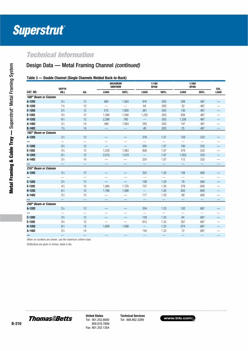
www.tnb.comUnited States
Tel: 901.252.8000800.816.7809
Fax: 901.252.1354
Technical Services
Tel: 888.862.3289B-210
Technical Information
Met
al F
ram
ing
& C
able
Tra
y —
Sup
erst
rut®
Met
al F
ram
ing
Syst
em
Table 3 — Double Channel (Single Channels Welded Back-to-Back)
CAT. NO.DEPTH
(IN.) GA.
MAXIMUM
UNIFORM
1/180
SPAN
1/360
SPANCOL.
LOADLOAD DEFL. LOAD DEFL. LOAD DEFL.
168" Beam or Column
A-1202 31⁄4 12 694 1.563 916 .933 208 .467 —
B-1202 15⁄8 12 — — 64 .933 32 .467 —
C-1202 23⁄4 12 515 1.850 261 .933 130 .467 —
E-1202 47⁄8 12 1,394 1.040 1,255 .933 626 .467 —
H-1202 61⁄2 12 2,298 .780 — .933 1,326 .467 —
A-1402 31⁄4 14 489 1.563 293 .933 147 .467 —
B-1402 15⁄8 14 — — 49 .933 25 .467 —
192" Beam or Column
A-1202 31⁄4 12 — — 318 1.07 159 .533 —
— — — — — — — — — —
C-1202 23⁄4 12 — — 200 1.07 100 .533 —
E-1202 47⁄8 12 1,220 1.363 958 1.07 479 .533 —
H-1202 61⁄2 12 2,010 1.019 — 1.07 1,053 .533 —
A-1402 31⁄4 14 — — 224 1.07 112 .533 —
— — — — — — — — — —
216" Beam or Column
A-1202 31⁄4 12 — — 252 1.20 126 .600 —
— — — — — — — — — —
C-1202 23⁄4 12 — — 158 1.20 79 .600 —
E-1202 47⁄8 12 1,084 1.725 757 1.20 379 .600 —
H-1202 61⁄2 12 1,788 1.288 — 1.20 832 .600 —
A-1402 31⁄4 14 — — 177 1.20 89 .600 —
— — — — — — — — — —
240" Beam or Column
A-1202 31⁄4 12 — — 204 1.33 102 .667 —
— — — — — — — — — —
C-1202 23⁄4 12 — — 128 1.33 64 .667 —
E-1202 47⁄8 12 — — 613 1.33 307 .667 —
H-1202 61⁄2 12 1,609 1.588 — 1.33 674 .667 —
A-1402 31⁄4 14 144 1.33 72 .667 —
— — — — — — — — — —
When no numbers are shown, use the maximum uniform load.
Deflections are given in inches; loads in lbs.
Design Data — Metal Framing Channel (continued)
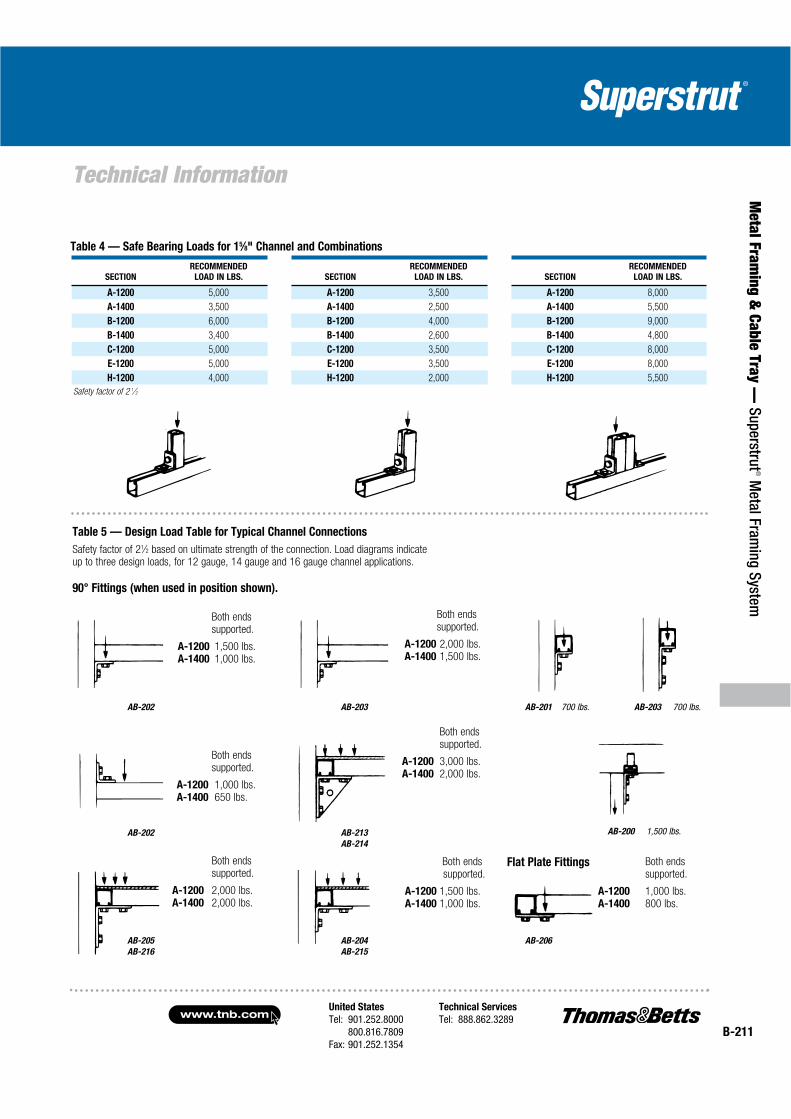
United States
Tel: 901.252.8000800.816.7809
Fax: 901.252.1354
Technical Services
Tel: 888.862.3289www.tnb.com
B-211
Technical Information
Metal Fram
ing & Cable Tray —
Superstrut® M
etal Framing System
Both ends supported.
A-1200 1,500 lbs.A-1400 1,000 lbs.
Both endssupported.
A-1200 3,000 lbs.A-1400 2,000 lbs.
Both endssupported.
A-1200 2,000 lbs.A-1400 1,500 lbs.
Both ends supported.
A-1200 2,000 lbs.A-1400 2,000 lbs.
Both endssupported.
A-1200 1,000 lbs.A-1400 650 lbs.
Both ends supported.
A-1200 1,500 lbs.A-1400 1,000 lbs.
Both ends supported.
A-1200 1,000 lbs.A-1400 800 lbs.
AB-202 AB-203
AB-200 1,500 lbs.
AB-203 700 lbs.AB-201 700 lbs.
AB-213
AB-214
AB-202
Flat Plate Fittings
SECTION
RECOMMENDED
LOAD IN LBS. SECTION
RECOMMENDED
LOAD IN LBS. SECTION
RECOMMENDED
LOAD IN LBS.
A-1200 5,000 A-1200 3,500 A-1200 8,000
A-1400 3,500 A-1400 2,500 A-1400 5,500
B-1200 6,000 B-1200 4,000 B-1200 9,000
B-1400 3,400 B-1400 2,600 B-1400 4,800
C-1200 5,000 C-1200 3,500 C-1200 8,000
E-1200 5,000 E-1200 3,500 E-1200 8,000
H-1200 4,000 H-1200 2,000 H-1200 5,500
Safety factor of 2 1⁄2
Table 4 — Safe Bearing Loads for 15⁄8" Channel and Combinations
Table 5 — Design Load Table for Typical Channel Connections
Safety factor of 21⁄2 based on ultimate strength of the connection. Load diagrams indicate up to three design loads, for 12 gauge, 14 gauge and 16 gauge channel applications.
90° Fittings (when used in position shown).
AB-206AB-205
AB-216
AB-204
AB-215

www.tnb.comUnited States
Tel: 901.252.8000800.816.7809
Fax: 901.252.1354
Technical Services
Tel: 888.862.3289B-212
Technical Information
Met
al F
ram
ing
& C
able
Tra
y —
Sup
erst
rut®
Met
al F
ram
ing
Syst
em Design Applications
Cantilever Beams
Simple Beams
Beams Fixed on One End, Supported at Other
Beams Fixed at Both Ends

United States
Tel: 901.252.8000800.816.7809
Fax: 901.252.1354
Technical Services
Tel: 888.862.3289www.tnb.com
B-213
Technical Information
Metal Fram
ing & Cable Tray —
Superstrut® M
etal Framing System
Load tables on pages B-200–B-210 for A, B, C, E and H series channel are for single span beams supported at the ends. These can be used in the majority of cases. There are times when it is necessary to know what happens with other loading and support conditions. Some common arrangements are shown in Table 6. Simply multiply the loads from the Design Load Tables times the factors given in Table 6. Examples shown on page B-214.
Table 6 — Conversion Factors for Beams with Various Static Loading Conditions
LOAD AND SUPPORT CONDITION
LOAD
FACTOR
DEFLECTION
FACTOR
1. Simple Beam — Uniform Load 1.00 1.00
2. Simple Beam — Concentrated Load at Center .50 1.25
3. Simple Beam — Two Equal Concentrated Loads at 1⁄4 Points 1.00 1.10
4. Beam Fixed at Both Ends — Uniform Load 1.50 .30
5. Beam Fixed at Both Ends — Concentrated Load at Center 1.00 .40
6. Cantilever Beam — Uniform Load .25 2.40
7. Cantilever Beam — Concentrated Load at End .12 3.20
8. Continuous Beam — Two Equal Spans — Uniform Load on One Span 1.30 .92
9. Continuous Beam — Two Equal Spans 1.00 .42
10. Continuous Beam — Two Equal Spans — Concentrated Load at Center of One Span .62 .71
11. Continuous Beam — Two Equal Spans — Concentrated Load at Center of Both Spans .67 .48
Span Span
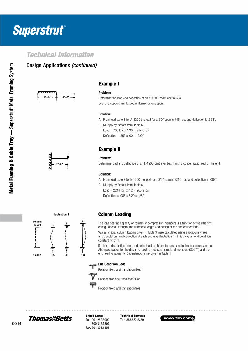
www.tnb.comUnited States
Tel: 901.252.8000800.816.7809
Fax: 901.252.1354
Technical Services
Tel: 888.862.3289B-214
Technical Information
Met
al F
ram
ing
& C
able
Tra
y —
Sup
erst
rut®
Met
al F
ram
ing
Syst
em Design Applications (continued)
Column Loading
The load bearing capacity of column or compression members is a function of the inherent configurational strength, the unbraced length and design of the end connections.
Values of axial column loading given in Table 3 were calculated using a rotationally free and translation fixed correction at each end (see illustration I). This gives an end condition constant (K) of 1.
If other end conditions are used, axial loading should be calculated using procedures in the AISI specification for the design of cold formed steel structural members (SG671) and the engineering values for Superstrut channel given in Table 1.
End Condition Code
Rotation fixed and translation fixed
Rotation free and translation fixed
Rotation fixed and translation free
Example I
Problem:
Determine the load and deflection of an A-1200 beam continuous
over one support and loaded uniformly on one span.
Solution:
A. From load table 3 for A-1200 the load for a 5'0" span is 706 lbs. and deflection is .358".
B. Multiply by factors from Table 6.
Load = 706 lbs. x 1.30 = 917.8 lbs.
Deflection = .358 x .92 = .329"
Example Ii
Problem:
Determine load and deflection of an E-1200 cantilever beam with a concentrated load on the end.
Solution:
A. From load table 3 for E-1200 the load for a 3'0" span is 2216 lbs. and deflection is .088".
B. Multiply by factors from Table 6.
Load = 2216 lbs. x .12 = 265.9 lbs.
Deflection = .088 x 3.20 = .282"
5"–0" 5"–0"
3"–0"
.65 .80 1.0K Value
Column
Height
Illustration 1
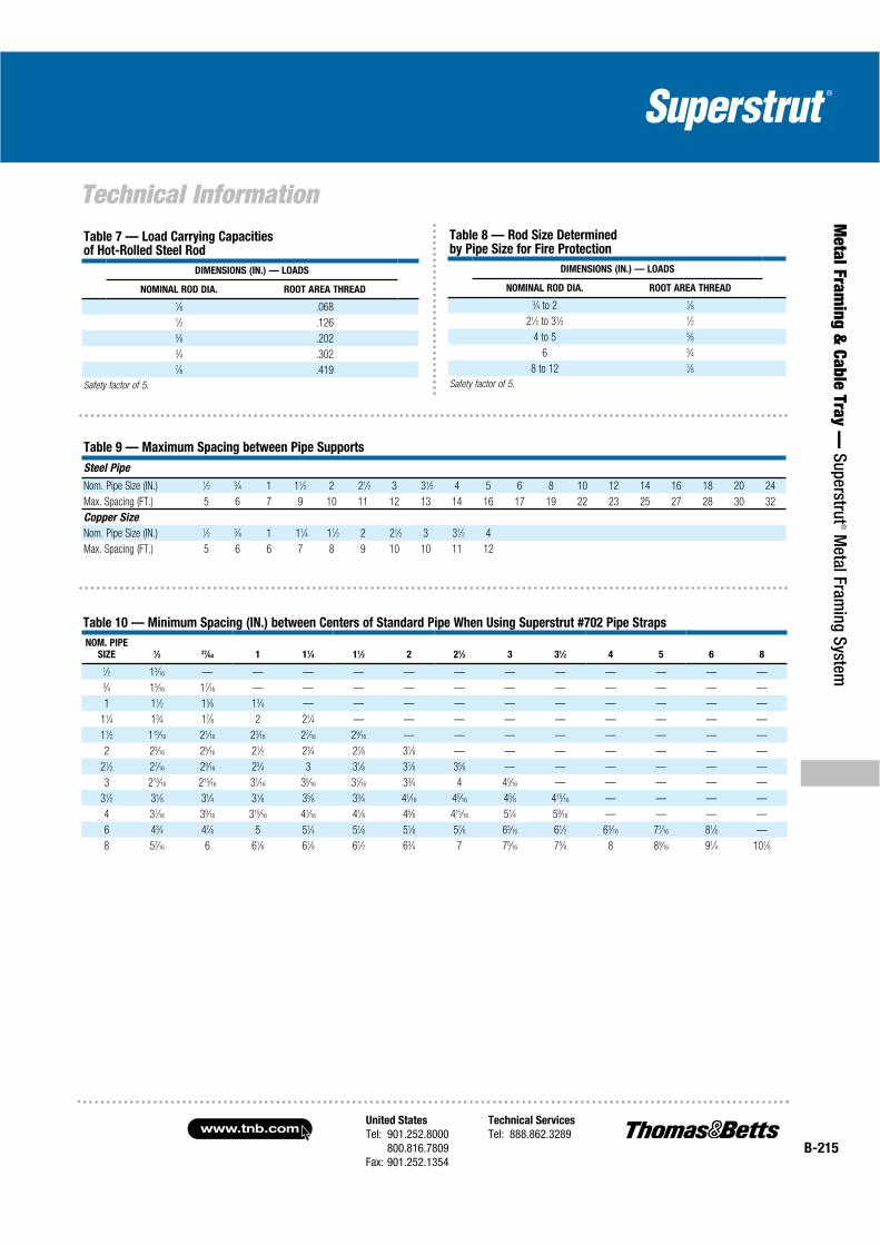
United States
Tel: 901.252.8000800.816.7809
Fax: 901.252.1354
Technical Services
Tel: 888.862.3289www.tnb.com
B-215
Technical Information
Metal Fram
ing & Cable Tray —
Superstrut® M
etal Framing System
Table 9 — Maximum Spacing between Pipe Supports
Steel Pipe
Nom. Pipe Size (IN.) 1⁄2 3⁄4 1 11⁄2 2 21⁄2 3 31⁄2 4 5 6 8 10 12 14 16 18 20 24
Max. Spacing (FT.) 5 6 7 9 10 11 12 13 14 16 17 19 22 23 25 27 28 30 32
Copper Size
Nom. Pipe Size (IN.) 1⁄2 3⁄4 1 11⁄4 11⁄2 2 21⁄2 3 31⁄2 4
Max. Spacing (FT.) 5 6 6 7 8 9 10 10 11 12
Table 10 — Minimum Spacing (IN.) between Centers of Standard Pipe When Using Superstrut #702 Pipe Straps
NOM. PIPE
SIZE 1⁄2 37⁄64 1 11⁄4 11⁄2 2 21⁄2 3 31⁄2 4 5 6 8
1⁄2 13⁄16 — — — — — — — — — — — —3⁄4 15⁄16 17⁄16 — — — — — — — — — — —
1 11⁄2 15⁄8 13⁄4 — — — — — — — — — —
11⁄4 13⁄4 17⁄8 2 21⁄4 — — — — — — — — —
11⁄2 115⁄16 21⁄16 23⁄16 27⁄16 29⁄16 — — — — — — — —
2 23⁄16 25⁄16 21⁄2 23⁄4 27⁄8 31⁄8 — — — — — — —
21⁄2 27⁄16 29⁄16 23⁄4 3 31⁄8 31⁄8 35⁄8 — — — — — —
3 213⁄16 215⁄16 31⁄16 35⁄16 37⁄16 33⁄4 4 45⁄16 — — — — —
31⁄2 31⁄8 31⁄4 31⁄8 35⁄8 33⁄4 41⁄16 45⁄16 45⁄8 415⁄16 — — — —
4 37⁄16 39⁄16 315⁄16 41⁄16 41⁄8 45⁄8 415⁄16 51⁄4 59⁄16 — — — —
6 43⁄4 47⁄8 5 51⁄4 51⁄8 51⁄8 57⁄8 63⁄16 61⁄2 63⁄16 77⁄16 81⁄8 —
8 57⁄16 6 61⁄8 61⁄8 61⁄2 63⁄4 7 75⁄16 75⁄8 8 89⁄16 91⁄4 101⁄8
Table 7 — Load Carrying Capacities of Hot-Rolled Steel Rod
DIMENSIONS (IN.) — LOADS
NOMINAL ROD DIA. ROOT AREA THREAD
1⁄8 .0681⁄2 .1265⁄8 .2023⁄4 .3027⁄8 .419
Safety factor of 5.
Table 8 — Rod Size Determined by Pipe Size for Fire Protection
DIMENSIONS (IN.) — LOADS
NOMINAL ROD DIA. ROOT AREA THREAD
3⁄4 to 2 1⁄8
21⁄2 to 31⁄2 1⁄2
4 to 5 5⁄8
6 3⁄4
8 to 12 7⁄8
Safety factor of 5.

www.tnb.comUnited States
Tel: 901.252.8000800.816.7809
Fax: 901.252.1354
Technical Services
Tel: 888.862.3289B-216
Technical Information
Met
al F
ram
ing
& C
able
Tra
y —
Sup
erst
rut®
Met
al F
ram
ing
Syst
em Design Applications (continued)
Table 11 — Standard Dimensions and Weights of Piping Materials and Conduit
MECHANICAL (SCHEDULE 40)
NOMINAL
STD. PIPE
SIZE
(IN.)
PIPE
O.D.
(IN.)
COUPLING
O.D.
(IN.)
1⁄2 .84 1.063⁄4 1.05 1.31
1 1.32 1.58
11⁄4 1.66 1.90
11⁄2 1.90 2.20
2 2.38 2.75
21⁄2 2.88 3.25
3 3.50 4.00
31⁄2 4.00 4.63
4 4.50 5.00
5 5.56 6.30
6 6.63 7.39
8 8.63 9.23
10 10.75 —
12 12.75 —
14 14.00 —
16 16.00 —
18 18.00 —
20 20.00 —
22 22.00 —
24 24.00 —
26 26.00 —
28 28.00 —
30 30.00 —
NOMINAL
CONDUIT
SIZE
(IN.)
ELECTRICAL CONDUIT
RIGID STEEL
CONDUIT
O.D.
(IN.)
THIN WALL (EMT)
CONDUIT
O.D.
(IN.)
1⁄2 .84 .713⁄4 1.05 .92
1 1.32 1.16
11⁄4 1.66 1.51
2 2.38 2.20
21⁄2 2.88 2.88
3 3.50 3.50
4 4.50 4.50
* Includes weight of heaviest conductor combination

United States
Tel: 901.252.8000800.816.7809
Fax: 901.252.1354
Technical Services
Tel: 888.862.3289www.tnb.com
B-217
Technical Information
Metal Fram
ing & Cable Tray —
Superstrut® M
etal Framing System
Table 12 — Extra Strong Pipe (Schedule 80)
A.S.A. B36.10 SCHEDULE
NOS. AND NOMINAL
WALL THICKNESS
DESIGNATIONS
NOMINAL
PIPE
SIZE
(IN.)
OUTSIDE
DIAMETER
(IN.)
WALL
THICKNESS
(IN.)
INSIDE
DIAMETER
(IN.)
EXTRA STRONG
PIPE AND
SCHEDULE 80 PIPE
(THROUGH 8")
3⁄8 .675 .126 .4231⁄2 .840 .147 .5463⁄4 1.050 .154 .742
1 1.315 .179 .957
11⁄4 1.660 .191 1.278
11⁄2 1.900 .200 1.500
2 2.375 .218 1.939
21⁄2 2.875 .276 2.323
3 3.500 .300 2.900
31⁄2 4.000 .318 3.364
4 4.500 .337 3.826
5 5.563 .375 4.813
6 6.625 .432 5.761
8 8.625 .500 7.625
10 10.750 .500 9.750
EXTRA STRONG PIPE
(10" THROUGH 24" OD)
12 12.750 .500 11.750
14 OD 14.000 .500 13.000
16 OD 16.000 .500 15.000
18 OD 18.000 .500 17.000
20 OD 20.000 .500 19.000
24 OD 24.000 .500 23.000
10 10.750 .593 9.564
SCHEDULE 80 PIPE
(10" THROUGH 24" OD)
12 12.750 .687 11.376
14 OD 14.000 .750 12.500
16 OD 16.000 .842 14.314
18 OD 18.000 .937 16.126
20 OD 20.000 1.031 17.938
24 OD 24.000 1.218 21.564
Table 13 — Pipe Covering Weights Thickness (Intended as Guide Only) and Weight of Calcium Silicate Covering
NOMINAL
PIPE
SIZE
260°
THICK.
(IN.)
360°
THICK.
(IN.)
440°
THICK.
(IN.)
525°
THICK.
(IN.)
600°
THICK.
(IN.)
700°
THICK.
(IN.)
800°
THICK.
(IN.)
1 1 1 1 1 11⁄2 11⁄2 11⁄2
11⁄4 1 1 1 1 11⁄2 11⁄2 2
11⁄2 1 1 1 1 11⁄2 11⁄2 2
2 1 1 1 11⁄2 11⁄2 2 2
21⁄2 1 1 1 11⁄2 11⁄2 2 21⁄2
3 1 1 1 11⁄2 11⁄2 2 21⁄2
31⁄2 1 1 11⁄2 11⁄2 2 2 21⁄2
4 1 1 11⁄2 11⁄2 2 2 21⁄2
5 1 1 11⁄2 11⁄2 2 2 21⁄2
6 11⁄2 11⁄2 11⁄2 11⁄2 2 2 21⁄2
8 11⁄2 11⁄2 11⁄2 11⁄2 2 2 21⁄2

www.tnb.comUnited States
Tel: 901.252.8000800.816.7809
Fax: 901.252.1354
Technical Services
Tel: 888.862.3289B-218
Technical Information
Met
al F
ram
ing
& C
able
Tra
y —
Sup
erst
rut®
Met
al F
ram
ing
Syst
em Design Applications (continued)
Table 14 — Column Loading for Rack Construction
COLUM
HEIGHT CAT. NO.
ALLOWABLE LOAD IN LBS. PER UPRIGHT
NUMBER OF SHELVES PER UPRIGHT
2 3 4 5 6 7 8 9 10
6' A-1200 2,237 1,925 1,650 1,437 1,290 — — — —
A-1202 4,170 3,580 3,100 2,730 2,450 — — — —
B-1400 800 820 790 700 630 — — — —
B-1402 1,930 1,700 1,500 1,300 1,190 — — — —
7' A-1200 2,150 1,850 1,630 1,425 1,280 1,150 — — —
A-1202 4,000 3,525 3,000 2,700 2,430 2,200 — — —
B-1400 650 790 760 685 615 550 — — —
B-1402 1,800 1,650 1,450 1,300 1,180 750 — — —
8' A-1200 2,000 1,820 1,600 1,400 1,250 1,150 1,050 — —
A-1202 3,900 3,475 3,000 2,700 2,400 2,185 2,000 — —
B-1400 580 750 730 660 610 540 510 — —
B-1402 1,650 1,610 1,450 1,300 1,160 940 970 — —
9' A-1200 1,950 1,780 1,575 1,400 1,250 1,130 1,030 950 —
A-1202 3,800 3,400 3,020 2,675 2,400 2,180 1,975 1,800 —
B-1400 — 600 665 600 580 540 500 475 —
B-1402 1,500 1,500 1,430 1,275 1,160 1,000 900 800 —
10' A-1200 1,870 1,700 1,500 1,300 1,200 1,100 1,000 900 800
A-1202 3,600 3,300 3,000 2,650 2,350 2,000 1,975 1,800 1,650
B-1400 — 550 650 625 580 535 490 450 425
B-1402 1,450 1,480 1,400 1,250 1,140 1,040 960 885 825
(pagesB-200–B-210)
Column height, equal shelf spacing
Typical general storage rack for use with plywood or other decking

United States
Tel: 901.252.8000800.816.7809
Fax: 901.252.1354
Technical Services
Tel: 888.862.3289www.tnb.com
B-219
Technical Information
Metal Fram
ing & Cable Tray —
Superstrut® M
etal Framing System
F-112
Forged Steel TurnbuckleSizes 3⁄8" through 11⁄2" rod
Federal Type 13
SP69 Type 13
C-755 T/C-757 T
Center I-Beam ClampFederal Type 21
SP69 Type 21
452
Steel Concrete InsertFederal Type 19
SP69 Type 18
CL-710
Light-Duty Clevis HangerSizes 1⁄2" through 4"
Federal Type 12
F-111
Forged Steel ClevisSizes 3⁄8" through 11⁄2" rod
Federal Type 14
SP69 Type 13
C-711
“J” Pipe HangerSizes 1⁄2" through 8" pipe
SP69 Type 5
M-777
Junior Top Beam C-ClampSizes 3⁄8" through 1⁄2" rod
SP69 Type 18
M-778
Top Beam C-ClampSizes 3⁄8" through 3⁄4" rod
SP69 Type 19
E-120-A
Forged Steel Weldless Eye Nut Sizes 3⁄8" through 11⁄2" rod
Federal Type 17
SP69 Type 17
M-718/MT-718
MI Split Pipe Ring w/wo turnbuckle adj.
Sizes 1⁄2" through 8" IPS1⁄2" through 4" tube
Federal Type 11
SP69 Type 12
M-775-L/C-775-L
MI or Steel C-ClampSizes 3⁄8" through 7⁄8"
Federal Type 23
SP69 Type 23
M-117
MI Socket only forS Split Ring Hanger
Sizes 3⁄8" through 7⁄8" RodFederal Type 16
SP69 Type 16
C-727/CT-727
Adj. Swivel Ring HangerSizes 1⁄2" through 8" IPS
1⁄2" through 4" tubeFederal Type 10
SP69 Type 10
H-115
U-BoltSizes 1⁄2" through 24" IPS
Federal Type 24
SP69 Type 24
C-710
Adj. Steel ClevisSizes 3⁄4" through 20" IPS
Federal Type 1
SP69 Type 1
CF-710
Adj. Steel Band HangerSizes 1⁄2" through 8"
IPS 3⁄4" through 4" tubeFederal Type 7
C-725
Steel Pipe ClampSizes 11⁄2" through 24" IPS
Federal Type 4
SP69 Type 4
C-720/CT-720
Extension Pipe or Riser ClampSizes 3⁄4" through 20"
IPS 1⁄2" through 6" tubeFederal Type 8
SP69 Type 8
C-726
Steel Double Bolt Pipe ClampSizes 11⁄2" through 24" IPS
Federal Type 3
SP69 Type 3
Federal Specifications (WW-H-171)/ Manufacturers Society Specifications (MSS SP69)
C-780
Welded attachment as shown or inverted less bolt
Federal Type 22
SP69 Type 22
A RodSize
“B”Max. Dia.
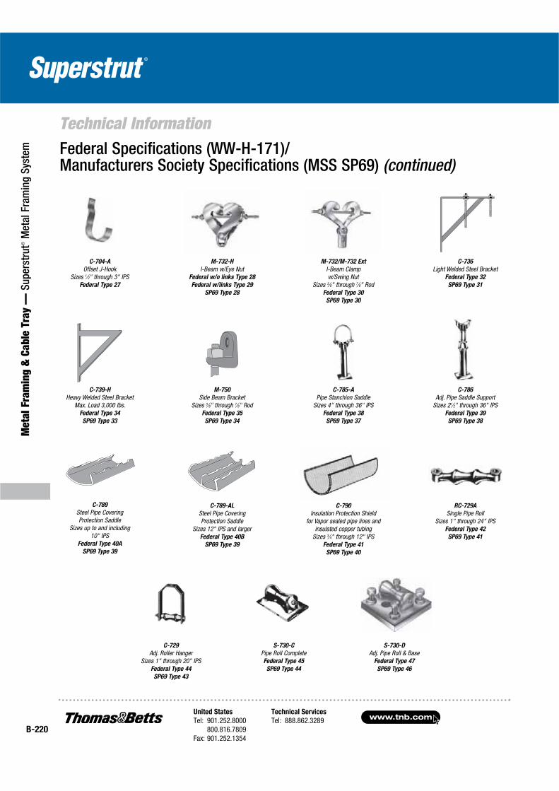
www.tnb.comUnited States
Tel: 901.252.8000800.816.7809
Fax: 901.252.1354
Technical Services
Tel: 888.862.3289B-220
Technical Information
Met
al F
ram
ing
& C
able
Tra
y —
Sup
erst
rut®
Met
al F
ram
ing
Syst
em Federal Specifications (WW-H-171)/Manufacturers Society Specifications (MSS SP69) (continued)
C-739-H
Heavy Welded Steel BracketMax. Load 3,000 lbs.
Federal Type 34
SP69 Type 33
C-736
Light Welded Steel BracketFederal Type 32
SP69 Type 31
M-732/M-732 Ext
I-Beam Clamp w/Swing Nut
Sizes 3⁄8" through 7⁄8" RodFederal Type 30
SP69 Type 30
M-732-H
I-Beam w/Eye NutFederal w/o links Type 28
Federal w/links Type 29
SP69 Type 28
C-704-A
Offset J-HookSizes 1⁄2" through 3" IPS
Federal Type 27
C-789
Steel Pipe Covering Protection Saddle
Sizes up to and including10" IPS
Federal Type 40A
SP69 Type 39
C-786
Adj. Pipe Saddle SupportSizes 21⁄2" through 36" IPS
Federal Type 39
SP69 Type 38
C-785-A
Pipe Stanchion SaddleSizes 4" through 36" IPS
Federal Type 38
SP69 Type 37
M-750
Side Beam BracketSizes 3⁄8" through 7⁄8" Rod
Federal Type 35
SP69 Type 34
S-730-C
Pipe Roll CompleteFederal Type 45
SP69 Type 44
C-729
Adj. Roller HangerSizes 1" through 20" IPS
Federal Type 44
SP69 Type 43
RC-729A
Single Pipe RollSizes 1" through 24" IPS
Federal Type 42
SP69 Type 41
C-790
Insulation Protection Shieldfor Vapor sealed pipe lines and
insulated copper tubingSizes 3⁄4" through 12" IPS
Federal Type 41
SP69 Type 40
C-789-AL
Steel Pipe Covering Protection Saddle
Sizes 12" IPS and largerFederal Type 40B
SP69 Type 39
S-730-D
Adj. Pipe Roll & BaseFederal Type 47
SP69 Type 46