SuperStack Switch Management Guide - Accueil -...
248
http://www.3com.com/ Part No. DUA1695-0BAA05 Published August 2000 SuperStack ® Switch Management Guide For units in the SuperStack Switch 1100/3300 and 610/630 Family Management Software Version 2.60
Transcript of SuperStack Switch Management Guide - Accueil -...
SuperStack® Switch Management Guide
http://www.3com.com/
Part No. DUA1695-0BAA05Published August 2000
For units in the SuperStack Switch 1100/3300 and 610/630 FamilyManagement Software Version 2.60
3Com Corporation5400 Bayfront Plaza Santa Clara, California 95052-8145
Copyright © 2000, 3Com Technologies. All rights reserved. No part of this documentation may be reproduced in any form or by any means or used to make any derivative work (such as translation, transformation, or adaptation) without written permission from 3Com Technologies.
3Com Technologies reserves the right to revise this documentation and to make changes in content from time to time without obligation on the part of 3Com Technologies to provide notification of such revision or change.
3Com Technologies provides this documentation without warranty, term, or condition of any kind, either implied or expressed, including, but not limited to, the implied warranties, terms or conditions of merchantability, satisfactory quality, and fitness for a particular purpose. 3Com may make improvements or changes in the product(s) and/or the program(s) described in this documentation at any time.
If there is any software on removable media described in this documentation, it is furnished under a license agreement included with the product as a separate document, in the hard copy documentation, or on the removable media in a directory file named LICENSE.TXT or !LICENSE.TXT. If you are unable to locate a copy, please contact 3Com and a copy will be provided to you.
UNITED STATES GOVERNMENT LEGEND
If you are a United States government agency, then this documentation and the software described herein are provided to you subject to the following:
All technical data and computer software are commercial in nature and developed solely at private expense. Software is delivered as “Commercial Computer Software” as defined in DFARS 252.227-7014 (June 1995) or as a “commercial item” as defined in FAR 2.101(a) and as such is provided with only such rights as are provided in 3Com’s standard commercial license for the Software. Technical data is provided with limited rights only as provided in DFAR 252.227-7015 (Nov 1995) or FAR 52.227-14 (June 1987), whichever is applicable. You agree not to remove or deface any portion of any legend provided on any licensed program or documentation contained in, or delivered to you in conjunction with, this User Guide.
Unless otherwise indicated, 3Com registered trademarks are registered in the United States and may or may not be registered in other countries.
3Com, SuperStack, and Transcend are registered trademarks of 3Com Corporation. The 3Com logo,CoreBuilder are trademarks of 3Com Corporation.
Intel and Pentium are registered trademarks of Intel Corporation. Microsoft, MS-DOS, Windows, and Windows NT are registered trademarks of Microsoft Corporation. Novell and NetWare are registered trademarks of Novell, Inc. UNIX is a registered trademark in the United States and other countries, licensed exclusively through X/Open Company, Ltd.
All other company and product names may be trademarks of the respective companies with which they are associated.
ENVIRONMENTAL STATEMENT
It is the policy of 3Com Corporation to be environmentally-friendly in all operations. To uphold our policy, we are committed to:
Establishing environmental performance standards that comply with national legislation and regulations.
Conserving energy, materials and natural resources in all operations.
Reducing the waste generated by all operations. Ensuring that all waste conforms to recognized environmental standards. Maximizing the recyclable and reusable content of all products.
Ensuring that all products can be recycled, reused and disposed of safely.
Ensuring that all products are labelled according to recognized environmental standards.
Improving our environmental record on a continual basis.
End of Life Statement
3Com processes allow for the recovery, reclamation and safe disposal of all end-of-life electronic components.
Regulated Materials Statement
3Com products do not contain any hazardous or ozone-depleting material.
Environmental Statement about the Documentation
The documentation for this product is printed on paper that comes from sustainable, managed forests; it is fully biodegradable and recyclable, and is completely chlorine-free. The varnish is environmentally-friendly, and the inks are vegetable-based with a low heavy-metal content.
CONTENTS
ABOUT THIS GUIDE
Conventions 13Related Documentation 15Year 2000 Compliance 15Documentation Comments 16Product Registration 16
I Getting Started with Management
1 SUPERSTACK SWITCH MANAGEMENT SOFTWARE
What is Management Software? 20Summary of Software Features 20Software Features Explained 21
Stack Management 21Forwarding Modes 21Duplex Modes 22Flow Control 23Traffic Prioritization 23PACE 24Security 24Resilient Links 25Port Trunks 25Broadcast Storm Control 26Virtual LANs 26FastIP 26Multicast Filtering 27Spanning Tree Protocol 27RMON 27Roving Analysis 28Management 28
Default Settings 29
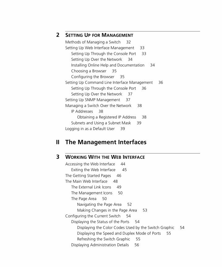
2 SETTING UP FOR MANAGEMENT
Methods of Managing a Switch 32Setting Up Web Interface Management 33
Setting Up Through the Console Port 33Setting Up Over the Network 34Installing Online Help and Documentation 34Choosing a Browser 35Configuring the Browser 35
Setting Up Command Line Interface Management 36Setting Up Through the Console Port 36Setting Up Over the Network 37
Setting Up SNMP Management 37Managing a Switch Over the Network 38
IP Addresses 38Obtaining a Registered IP Address 38
Subnets and Using a Subnet Mask 39Logging in as a Default User 39
II The Management Interfaces
3 WORKING WITH THE WEB INTERFACE
Accessing the Web Interface 44Exiting the Web Interface 45
The Getting Started Pages 46The Main Web Interface 48
The External Link Icons 49The Management Icons 50The Page Area 50
Navigating the Page Area 52Making Changes in the Page Area 53
Configuring the Current Switch 54Displaying the Status of the Ports 54
Displaying the Color Codes Used by the Switch Graphic 54Displaying the Speed and Duplex Mode of Ports 55Refreshing the Switch Graphic 55
Displaying Administration Details 56
Setting Up IP Information 58Configuring a Port 59Configuring the Console Port 66
Changing the Management Settings for the Stack 67Specifying a Descriptive Name 67Changing Your Password 68Specifying a Physical Location 69Accessing the Getting Started Pages 69Specifying the Location of the Online Help and Documentation 70Specifying Contact Details 71
Configuring the Stack 71Configuring the Switch Database 72
What is the Switch Database? 72Displaying the Switch Database 73Inserting Permanent Entries 74Deleting Entries 75
Configuring the Advanced Stack Settings 76Setting Up Resilient Links 79
What are Resilient Links? 79Displaying Resilient Link Pairs 80Creating a Resilient Link Pair 80Deleting a Resilient Link Pair 81Swapping the Active Port of a Resilient Link Pair 81
Setting Up Port Trunks 81What are Port Trunks? 82Displaying the Ports that Belong to Each Port Trunk 82Placing Ports in a Port Trunk 82
Configuring VLANs 83What are VLANs? 84Defining VLAN Information 84Editing VLAN Information 84Deleting VLAN Information 85Displaying the Ports that Belong to Each VLAN 85Placing Ports in Single VLANs 85Placing Ports in Multiple VLANs Using VLT Tagging 85Placing Ports in Multiple VLANs Using 802.1Q Tagging 85
Setting Up Roving Analysis Ports 86What is Roving Analysis? 87
Defining Monitor Ports and Analysis Ports 87Enabling the Roving Analysis System 88
Resetting All the Units in the Stack 88What Happens During a Reset? 88
Initializing All the Units in the Stack 88What Happens During an Initialization? 88
Upgrading Management Software 89Displaying Statistics for the Current Switch 91
Displaying Unit Statistics 91Interpreting the Statistics 92
Displaying Port Statistics 92Interpreting the Statistics 94
4 WORKING WITH THE COMMAND LINE INTERFACE
Accessing the Interface 96Exiting the Interface 96How Many Users Can Access the Interface? 97
About the Interface Menus 97Entering Commands 99Displaying Menus 100Obtaining Help 100
A Quick Guide to the Commands 101Displaying and Changing Bridging/VLANs Information 105
Setting the Bridge Address Aging Time 105Displaying Bridge Information 105Enabling and Disabling IGMP Snooping 107Enabling and Disabling Router Port Auto-Discovery 108Manually Identifying a Router Port 108Displaying all Router Ports 108Removing a Router Port 109Adding a Statically Configured Address to a Switch Database 110Finding a MAC Address 110Displaying MAC Addresses for a Port 111Removing MAC Addresses from a Port 111Displaying Port Information 111Setting the Spanning Tree Path Cost 112Enabling and Disabling Spanning Tree Fast Start 112
Displaying Port Summary Information 113Enabling and Disabling VLT Tagging on a Port 114Setting the Bridge Spanning Tree Forward Delay 114Setting the Bridge Spanning Tree Hello Timer 115Setting the Bridge Spanning Tree Maximum Age 115Setting the Spanning Tree Bridge Priority 115Enabling and Disabling Spanning Tree on a Bridge 116Adding a Port to a VLAN 116Creating a VLAN 116Deleting a VLAN 117Displaying Detailed VLAN Information 117Modifying a VLAN 118Removing a Port from a VLAN 119Displaying Summary VLAN Information 119
Displaying and Changing Port Information 120Enabling and Disabling Ports 120Specifying the Speed and Duplex Mode 121Enabling and Disabling Auto-negotiation 121Enabling and Disabling Flow Control 123Displaying Port Statistics 123
Packet Size Analysis 126Displaying Port Summary Information 126
Displaying and Changing System Feature Information 127Setting up a Roving Analysis Port 127Displaying the Roving Analysis Port Information 127Removing a Roving Analysis Port 128Starting Data Monitoring 128Stopping Data Monitoring 129Enabling and Disabling Broadcast Storm Control 129Setting Up a Resilient Link 130Displaying Resilient Link Information 131Removing a Resilient Link 131Swapping over Active Links 131Adding a Port to a Trunk 132Displaying Detailed Trunk Information 132Removing a Port from a Trunk 133Displaying Summary Trunk Information 133
Displaying and Changing IP-related Information 133

Specifying IP and SLIP Information 134Displaying IP and SLIP Information 135Enabling and Disabling BOOTP 135Pinging Other Devices 136Resetting the IP Configuration 137
Displaying and Changing SNMP-related Information 137Specifying SNMP Community Strings 137Specifying Trap Destination Details 138Displaying Trap Destination Details 138Modifying Trap Destination Details 139Removing Trap Destination Details 139Performing an SNMP GET Command 139Performing an SNMP GETNEXT Command 140Performing an SNMP SET Command 140
Displaying and Changing Stack Information 141Moving the Focus of the Command Line Interface 142
Returning the Focus to the Previous Switch Unit 142Specifying Stack Administration Details 142Displaying Switch Administration Details 143Displaying Stack Summary Information 145Configuring Intelligent Modules 146
Setting Module Configuration 146Displaying Module Configuration 146Enabling and Disabling the Module Interface 146
Changing Your Password 147Specifying User Details 147Displaying User Details 148Modifying User Details 148Removing User Details 149Displaying Access Rights 149Modifying Access Rights 150Enabling and Disabling Remote Access 151Resetting All the Units in the Stack 151
What Happens During a Reset? 152Initializing All the Units in the Stack 152
What Happens During an Initialization? 152Upgrading Management Software 153
III Management Reference
5 PORT TRUNKSWhat are Port Trunks? 158Port Trunks and Your Switch 158Placing Ports in a Port Trunk 159Port Trunk Example 160
6 VIRTUAL LANS (VLANS)What are VLANs? 164Benefits of VLANs 164VLANs and Your Switch 165
The Default VLAN 165Defining New VLANs 166Untagged and Tagged VLANs 166Placing a Port in a Single VLAN 166Placing a Port in Multiple VLANs 166
802.1Q Tagging 166VLT Tagging 167
Using IEEE 802.1Q Learning 167Forwarding Traffic Containing Unknown 802.1Q Tags 168Connecting VLANs to Other VLANs 170Connecting to VLANs on Legacy Switch Units 170
VLAN Configuration for Beginners 171Simple Example: Using Untagged Connections 171Simple Example: Untagged Connections with Hubs 172Simple Example: 802.1Q Tagged Connections 174
VLAN Configuration - Advanced Examples 177Using 802.1Q Tagged Connections and 802.1Q Learning 177Connecting to a Legacy Network 178
7 FASTIPWhat is FastIP? 182How FastIP Works 182An Example 183FastIP and the Switch Database 186Enabling FastIP 187
8 MULTICAST FILTERING
What is a Multicast? 190What is Multicast Filtering? 190Multicast Filtering and Your Switch 191
IEEE 802.1p Multicast Filtering 191Enabling 802.1p Multicast Learning 191
IGMP Multicast Filtering 192Enabling IGMP Multicast Learning 192
Manual Filtering 192
9 SPANNING TREE PROTOCOL
What is STP? 194How STP Works 196
STP Requirements 196STP Calculation 197STP Configuration 197STP Reconfiguration 197An Example 198STP Configurations 199
Using STP on a Network with Multiple VLANs 201Connecting to STP Systems on Legacy Switch Units 202Enabling STP 202
10 RMONWhat is RMON? 204
The RMON Groups 204Statistics 204History 204Alarms 204Hosts 205Hosts Top N 205Matrix 205Events 205
Benefits of RMON 206RMON and Your Switch 207
The Alarm Events 208
The Default Alarm Settings 208The Audit Log 209
IV Problem Solving
11 PROBLEM SOLVING
Solving Web Interface Problems 214Solving Command Line Interface Problems 216Solving SNMP Management Software Problems 218Solving Serial Web Utility Problems 219Solving Management Software Upgrade Utility Problems 220Solving Other Problems 221
V Appendices and Index
A SERIAL WEB UTILITY
Introduction 227Installing the Serial Web Utility 227Using the Serial Web Utility 229
B MANAGEMENT SOFTWARE UPGRADE UTILITY
Using the Upgrade Utility 231
GLOSSARY
INDEX


ABOUT THIS GUIDE
This guide provides all the information you need to manage units in the SuperStack® II and Superstack 3 Switch 1100/3300 and 610/630 family with management software version 2.60.
The guide is intended for use by network administrators who are responsible for installing and setting up network equipment; consequently, it assumes a basic working knowledge of LANs (Local Area Networks).
Throughout this guide, the term stack refers to a number of Switch units that are managed as a single unit. However, a stack can contain a single Switch. In the case of the 610/630 family, stackability is not supported.
If the information in the release notes that are shipped with your product differs from the information in this guide, follow the instructions in the release notes.
Conventions Table 1 and Table 2 list conventions that are used throughout this guide.
Table 1 Notice Icons
Icon Notice Type Description
Information note Information that describes important features or instructions
Caution Information that alerts you to potential loss of data or potential damage to an application, system, or device
Warning Information that alerts you to potential personal injury
14 ABOUT THIS GUIDE
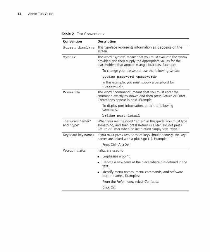
Table 2 Text Conventions
Convention Description
Screen displays This typeface represents information as it appears on the screen.
Syntax The word “syntax” means that you must evaluate the syntax provided and then supply the appropriate values for the placeholders that appear in angle brackets. Example:
To change your password, use the following syntax:
system password <password>
In this example, you must supply a password for <password>.
Commands The word “command” means that you must enter the command exactly as shown and then press Return or Enter. Commands appear in bold. Example:
To display port information, enter the following command:
bridge port detail
The words “enter” and “type”
When you see the word “enter” in this guide, you must type something, and then press Return or Enter. Do not press Return or Enter when an instruction simply says “type.”
Keyboard key names If you must press two or more keys simultaneously, the key names are linked with a plus sign (+). Example:
Press Ctrl+Alt+Del
Words in italics Italics are used to:
� Emphasize a point.
� Denote a new term at the place where it is defined in the text.
� Identify menu names, menu commands, and software button names. Examples:
From the Help menu, select Contents.
Click OK.
Related Documentation 15
Related Documentation
In addition to this guide, each document set in the Switch 1100/3300 and 610/630 family includes the following:
� User Guide
This guide contains all the hardware and installation information for the Switch.
� Quick Reference Guide
This guide contains a quick summary of the hardware and software information for the Switch
� Quick Installation Guide
This guide contains a summary of the package contents, and a quick summary of the installation information for the Switch.
� Release Notes
These notes provide information about the current software release, including new features, modifications, and known problems.
� SuperStack Switch Help
This help provides information about the web interface software of the Switch. It is supplied on the SuperStack Switch Family CD-ROM.
� SuperStack Switch README File
This file provides information about the current software release, including new features, modifications, and known problems.
In addition, there are other publications you may find useful:
� Documentation accompanying the Expansion Modules.
� Documentation accompanying the Transceiver Modules.
� Documentation accompanying the Advanced Redundant Power System.
Year 2000 Compliance
For information on Year 2000 compliance and 3Com products, visit the 3Com Year 2000 Web page:
http://www.3com.com/products/yr2000.html
16 ABOUT THIS GUIDE
Documentation Comments
Your suggestions are very important to us. They will help make our documentation more useful to you. Please e-mail comments about this document to 3Com at:
Please include the following information when commenting:
� Document title
� Document part number (on the title page)
� Page number (if appropriate)
Example:
� SuperStack Switch Management Guide
� Part Number DUA1695-0BAA04
� Page 21
Product Registration
You can now register your SuperStack Switch on the 3Com web site to receive up-to-date information on your product:
http://support.3com.com/warrantyregistration/register.pl

I
GETTING STARTED WITH MANAGEMENTChapter 1 SuperStack Switch Management Software
Chapter 2 Setting Up for Management

1
SUPERSTACK SWITCH MANAGEMENT SOFTWAREThis chapter contains introductory information about the SuperStack® Switch management software and how it can be used in your network. It covers the following topics:
� What is Management Software?
� Summary of Software Features
� Software Features Explained
� Default Settings
20 CHAPTER 1: SUPERSTACK SWITCH MANAGEMENT SOFTWARE
What is Management Software?
Your Switch contains software that allows you to change and monitor the way it works. This management software is not required to get the Switch working, but if you do use it, you may improve the efficiency of the Switch and therefore improve the overall performance of your network.
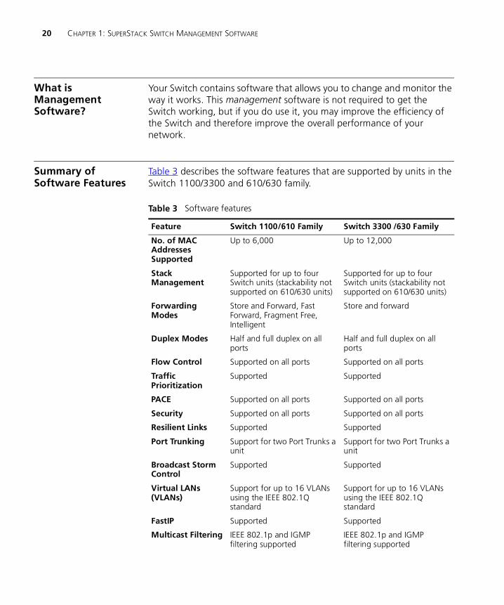
Summary of Software Features
Table 3 describes the software features that are supported by units in the Switch 1100/3300 and 610/630 family.
Table 3 Software features
Feature Switch 1100/610 Family Switch 3300 /630 Family
No. of MAC Addresses Supported
Up to 6,000 Up to 12,000
Stack Management
Supported for up to four Switch units (stackability not supported on 610/630 units)
Supported for up to four Switch units (stackability not supported on 610/630 units)
Forwarding Modes
Store and Forward, Fast Forward, Fragment Free, Intelligent
Store and forward
Duplex Modes Half and full duplex on all ports
Half and full duplex on all ports
Flow Control Supported on all ports Supported on all ports
Traffic Prioritization
Supported Supported
PACE Supported on all ports Supported on all ports
Security Supported on all ports Supported on all ports
Resilient Links Supported Supported
Port Trunking Support for two Port Trunks a unit
Support for two Port Trunks a unit
Broadcast Storm Control
Supported Supported
Virtual LANs (VLANs)
Support for up to 16 VLANs using the IEEE 802.1Q standard
Support for up to 16 VLANs using the IEEE 802.1Q standard
FastIP Supported Supported
Multicast Filtering IEEE 802.1p and IGMP filtering supported
IEEE 802.1p and IGMP filtering supported

Software Features Explained 21
Software Features Explained
Stack Management Units in the Switch 1100/3300 family can be interconnected so that they form a stack, that is, a group of devices that are managed as a single device.
Stackability is not supported by the Switch 610/630 units.
You can interconnect these Switch units together in two ways:
� The matrix port on the rear of each Switch allows you to connect two Switch units back-to-back. For this you need a Matrix Cable (part number 3C16965).
� The Expansion Module slot at the rear of each Switch allows you to install a Matrix Module (part number 3C16960). The Matrix Module provides four ports and allows you to interconnect up to four units using Matrix Cables.
For information about stacking Switch units, refer to Chapter 2 of the relevant Switch User Guide.
Forwarding Modes Units in the Switch 3300/630 family support Store and Forward packet forwarding mode. In this mode, received packets are buffered entirely before they are forwarded, which ensures that only good packets are forwarded to their destination.
Spanning Tree Protocol
Supported Supported
RMON Seven groups supported: Statistics, History, Alarms, Hosts, Hosts Top N, Matrix, Events
Seven groups supported: Statistics, History, Alarms, Hosts, Hosts Top N, Matrix, Events
Roving Analysis Supported Supported
Management Web interface, command line interface, and SNMP supported
Web interface, command line interface, and SNMP supported
Table 3 Software features
Feature Switch 1100/610 Family Switch 3300 /630 Family
22 CHAPTER 1: SUPERSTACK SWITCH MANAGEMENT SOFTWARE
Units in the Switch 1100/610 family support three forwarding modes in addition to Store and Forward:
� Fast Forward — Packets are forwarded as soon as the destination address is received and processed. With Fast Forward, packets take less time to be forwarded, but all error packets are propagated onto the network because no time is allowed for checking.
� Fragment Free — Packets are forwarded when at least 512 bits of the packet is received, which ensures that collision fragments are not propagated through the network. With Fragment Free, packets take less time to be forwarded, but all error packets except fragments are propagated.
� Intelligent — The Switch monitors the amount of error traffic on the network and changes the forwarding mode accordingly. If the Switch detects less than 20 errors a second, the forwarding mode is set to Fast Forward. If the Switch detects 20 or more errors a second, the forwarding mode is set to Store and Forward until the number of errors a second returns to zero.
For information about setting the forwarding mode for units in the Switch 1100/610 family, see “Configuring the Advanced Stack Settings” on page 76.
Duplex Modes All the ports on your Switch can be set to one of two duplex modes:
� Half duplex — Allows packets to be transmitted and received, but not simultaneously. This is the default Ethernet duplex mode.
� Full duplex — Allows packets to be transmitted and received simultaneously and, in effect, doubles the potential throughput of a link. In addition, full duplex supports 100BASE-FX cable runs of up to 2km (6562ft).
To communicate effectively, both ends of a link must use the same duplex mode. If the link uses an auto-negotiating connection, this is done automatically. If the link uses a connection that is not auto-negotiating, both ends must be set to half duplex or full duplex manually.
For more information about setting the duplex mode of a port, see “Configuring a Port” on page 59.
Software Features Explained 23
Flow Control All the ports on your Switch support flow control, which is a congestion control mechanism. Congestion is caused by one or more devices sending traffic to an already overloaded port on the Switch. Flow control prevents packet loss and inhibits the devices from generating more packets until the period of congestion ends.
Flow control is implemented in two ways:
� IEEE 802.3x standard for ports operating in full duplex.
� Intelligent Flow Management (IFM), a 3Com proprietary method of flow control, for ports operating in half duplex. IFM should only be enabled if the port is connected to another switch, or an endstation. If the port is connected to a repeated segment with local traffic, IFM should be disabled.
For information about enabling flow control on a port, see “Configuring a Port” on page 59.
Traffic Prioritization Your Switch supports IEEE 802.1p traffic prioritization, which allows data that has been assigned a high priority to be forwarded through the Switch without being obstructed by other data. The system works by using the multiple traffic queues that are present in the hardware of the Switch — high priority traffic is forwarded on a different queue from other traffic, and it is always given preference over the other traffic.
Traffic prioritization can be useful for critical applications that require a high Class of Service (CoS) from the network. This could include:
� Financial applications — Accounts departments that need immediate access to large files and spreadsheets at the end of the month.
� CAD/CAM design applications — Design departments that need priority connections to server farms and other devices for transferring large files.
� Converged network applications — Organizations with a converged network (that is, a network that uses the same infrastructure for voice data and traditional data) that require high quality voice data transmission at all times.
24 CHAPTER 1: SUPERSTACK SWITCH MANAGEMENT SOFTWARE
If you use IEEE 802.1p traffic prioritization, we recommend that all relevant ports on your Switch are placed in one or more Virtual LANs (VLANs) using 802.1Q tagging. For a brief explanation of VLANs, see “Virtual LANs” on page 26. For a detailed explanation of VLANs and 802.1Q tagging, see “Virtual LANs (VLANs)” on page 163.
PACE Your Switch supports PACE (Priority Access Control Enabled) which is a 3Com proprietary feature that allows multimedia traffic to move across a network effectively.
PACE provides two main features:
� Implicit Class of Service — This feature gives priority to traffic from multimedia applications, and provides the same functionality as IEEE 802.1p traffic prioritization (see “Traffic Prioritization” on page 23).
� Interactive Access — When two-way multimedia traffic passes over an Ethernet or Fast Ethernet network, interference can occur because access to the bandwidth is unequally allocated to traffic in one direction. The Interactive Access feature allocates the available bandwidth equally in both directions, therefore increasing the quality of the multimedia traffic.
For information about enabling PACE on an individual port, see “Configuring a Port” on page 59. For information about enabling PACE on a whole Switch or stack, see “Configuring the Advanced Stack Settings” on page 76.
Security Each port on your Switch can use a security feature that guards against unauthorized users connecting devices to your network. When security is enabled on a port, it enters Single Address Learning Mode. In this mode, the Switch:
� Removes all the MAC (Ethernet) addresses stored for the port in the Switch Database. For more information about the Switch Database, see “What is the Switch Database?” on page 72.
� Learns the address of the first packet it receives on the port.
� Defines the address as a permanent entry.
Once the first address is learned:
� The port is disabled if a different address is seen on the port.
Software Features Explained 25
� No other address can be learned until security is disabled or the address is manually removed from the database.
� The address cannot be learned on another port until security is disabled or the address is manually removed from the database.
For more information about enabling security on a port, see “Configuring a Port” on page 59.
Resilient Links The resilient link feature of the Switch enables you to protect critical links and prevent network downtime should those links fail. Setting up resilience ensures that if a main communication link fails, a standby duplicate link immediately and automatically takes over the task of the main link. Each main and standby link pair is referred to as a resilient link pair.
Resilient links are a simple method of creating redundancy that provides you with an instant reaction to link failure. Resilient links are quick to set up, you have full control over their configuration, and the port at the other end of the resilient link does not have to support any resilience feature.
For more information about resilient links, see “Setting Up Resilient Links” on page 79.
Port Trunks Your Switch supports port trunks — connections that allow devices to communicate using up to four links in parallel. Port trunks provide two benefits:
� They can potentially double, triple or quadruple the bandwidth of a connection.
� They can provide redundancy — if one link is broken, the other links share the traffic for that link.
For more information about port trunks, see “Port Trunks” on page 157.
26 CHAPTER 1: SUPERSTACK SWITCH MANAGEMENT SOFTWARE
Broadcast StormControl
Your Switch supports Broadcast Storm Control, a system that automatically creates an alarm for each port to monitor the level of broadcast traffic on that port. If the broadcast traffic level rises to 2976 frames per second, the broadcast traffic on the port is blocked until the broadcast traffic level drops to 1488 frames per second. This system prevents the overwhelming broadcast traffic that can result from network equipment which is faulty or configured incorrectly.
For more information about enabling Broadcast Storm Control, see “Configuring the Advanced Stack Settings” on page 76.
Virtual LANs Your Switch provides supports for up to 16 Virtual LANs (VLANs). A VLAN is a flexible group of devices that can be located anywhere in a network, but they communicate as if they are on the same physical segment. With VLANs, you can segment your network without being restricted by physical connections — a drawback of traditional network design. As an example, with VLANs you can segment your network according to:
� Departmental groups — For example, you can have one VLAN for the Marketing department, another for the Finance department, and another for the Development department.
� Hierarchical groups — For example, you can have one VLAN for directors, another for managers, and another for general staff.
� Usage groups — For example, you can have one VLAN for users of e-mail, and another for users of multimedia.
For more information, see “Virtual LANs (VLANs)” on page 163.
FastIP Your Switch supports FastIP, a system that reduces the load on routing devices when VLANs are implemented on your network.
Devices within different VLANs can only communicate using a routing device; if there is a large amount of inter-VLAN traffic, the router can become overloaded and network performance can be affected. FastIP allows your endstations and Switch units to find secure short-cuts for inter-VLAN traffic that bypass the routing device altogether.
For more information about FastIP, see “FastIP” on page 181.
Software Features Explained 27
Multicast Filtering Your Switch supports two multicast filtering systems:
� IEEE 802.1p, which uses the GARP Multicast Registration Protocol (GMRP)
� IGMP (Internet Group Management Protocol)
These systems allow the Switch to forward multicast traffic to the endstations that are interested rather than broadcasting the traffic to the whole network.
For more information, see “Multicast Filtering” on page 189.
Spanning TreeProtocol
Your Switch supports the Spanning Tree Protocol (STP), a bridge-based system that makes your network more resilient to link failure and also provides a protection from loops — one of the major causes of broadcast storms.
STP allows you to implement parallel paths for network traffic and uses a loop-detection process to:
� Discover the efficiency of each path.
� Enable the most efficient path (that is, the one that has the highest bandwidth).
� Disable the less efficient paths.
� Enable one of the less efficient paths if the most efficient path fails.
For information about STP, see “Spanning Tree Protocol” on page 193. For information about enabling STP, see “Configuring the Advanced Stack Settings” on page 76.
RMON Your Switch supports RMON (Remote Monitoring), a system that allows you to monitor LANs remotely. The Switch contains RMON probe software that continually collects statistics about the LAN segments connected to the Switch. If you have a management workstation with an RMON management application, the Switch can transfer these statistics to your workstation on request or when a pre-defined threshold is crossed.
For more information, see “RMON” on page 203.
28 CHAPTER 1: SUPERSTACK SWITCH MANAGEMENT SOFTWARE
Roving Analysis Your Switch supports roving analysis, a system that allows you to attach a network analyzer to one port and use it to monitor the traffic of other ports on the Switch. The system works by enabling you to define an analysis port (the port that is connected to the analyzer), and a monitor port (the port that is to be monitored). Once the pair are defined, and you enable the system, the Switch takes all the traffic going in and out of the monitor port and copies it to the analysis port.
Roving analysis is used when you need the functions of a network analyzer, but do not want to change the physical characteristics of the monitored segment by attaching an analyzer to that segment.
For information about setting up roving analysis ports, see “Setting Up Roving Analysis Ports” on page 86.
Management Your Switch can be managed using three methods:
� Web interface management — The Switch has an internal set of web pages that allow you to manage it using any Java-enabled Web browser. You can access the web interface using:
� A management workstation connected over the network
� A management workstation connected to the console port of the Switch, running the Serial Line Internet Protocol (SLIP)
� Command line interface management — The Switch has a command line interface that allows you to perform limited management. You can access the command line interface using:
� A terminal or terminal emulator connected over the network using Telnet
� A terminal or terminal emulator connected to the console port of the Switch
� SNMP management — You can manage the Switch using any network management application running the Simple Network Management Protocol (SNMP), such 3Com Transcend® Enterprise Manager software.
For information about setting up your Switch for management, see “Setting Up for Management” on page 31.
Default Settings 29
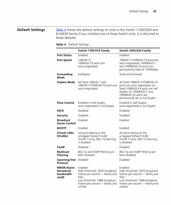
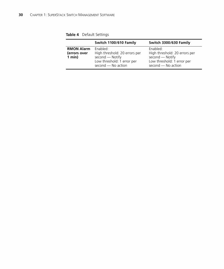
Default Settings Table 4 shows the default settings of units in the Switch 1100/3300 and 610/630 family. If you initialize one of these Switch units, it is returned to these defaults.
Table 4 Default Settings
Switch 1100/610 Family Switch 3300/630 Family
Port Status Enabled Enabled
Port Speed 10BASE-T/100BASE-TX ports are auto-negotiated.
10BASE-T/100BASE-TX ports are auto-negotiated; 1000BASE-T and 1000BASE-SX ports are permanently fixed at 1000Mbps
Forwarding Mode
Intelligent Store-and-forward
Duplex Mode All fixed 10BASE-T and 10BASE-T/100BASE-TX ports are auto-negotiated.
All fixed 10BASE-T/100BASE-TX ports are auto-negotiated; all fixed 100BASE-FX ports are half duplex; all 1000BASE-T and !000BASE-SX ports are permanently set to full duplex.
Flow Control Enabled in half duplex, auto-negotiated in full duplex
Enabled in half duplex, auto-negotiated in full duplex
PACE Disabled Disabled
Security Disabled Disabled
Broadcast Storm Control
Enabled Enabled
BOOTP Enabled Enabled
Virtual LANs (VLANs)
All ports belong to the untagged Default VLAN (VLAN 1) only; 802.1Q learning is disabled
All ports belong to the untagged Default VLAN (VLAN 1) only; 802.1Q learning is disabled
FastIP Disabled Disabled
Multicast Filtering
802.1p and IGMP filtering are both disabled
802.1p and IGMP filtering are both disabled
Spanning Tree Protocol
Disabled Disabled
RMON Alarm(broadcast bandwidth used)
Enabled: High threshold: 2976 broadcast frames per second — Notify and filterLow threshold: 1488 broadcast frames per second — Notify and unfilter
Enabled:High threshold: 2976 broadcast frames per second — Notify and filterLow threshold: 1488 broadcast frames per second — Notify and unfilter
30 CHAPTER 1: SUPERSTACK SWITCH MANAGEMENT SOFTWARE
RMON Alarm(errors over 1 min)
Enabled:High threshold: 20 errors per second — NotifyLow threshold: 1 error per second — No action
Enabled:High threshold: 20 errors per second — NotifyLow threshold: 1 error per second — No action
Table 4 Default Settings
Switch 1100/610 Family Switch 3300/630 Family
2
SETTING UP FOR MANAGEMENTThis chapter explains the various ways of managing a Switch, and details the steps required before you can configure a Switch to suit the needs of your network. It covers the following topics:
� Methods of Managing a Switch
� Setting Up Web Interface Management
� Setting Up Command Line Interface Management
� Setting Up SNMP Management
� Managing a Switch Over the Network
� Logging in as a Default User
32 CHAPTER 2: SETTING UP FOR MANAGEMENT
Methods of Managing a Switch
You can manage a Switch using one of the following methods:
� Web interface management — Each Switch has an internal set of web pages that allow you to manage the Switch using a Java®-enabled Web browser.
� Command line interface management — Each Switch has a command line interface that allows you to manage the Switch.
� SNMP management — You can manage a Switch using any Network Manager running the Simple Network Management Protocol (SNMP), such as 3Com Transcend® Enterprise Manager software.
For maximum manageability, we recommend that you use 3Com Transcend Enterprise Manager software.
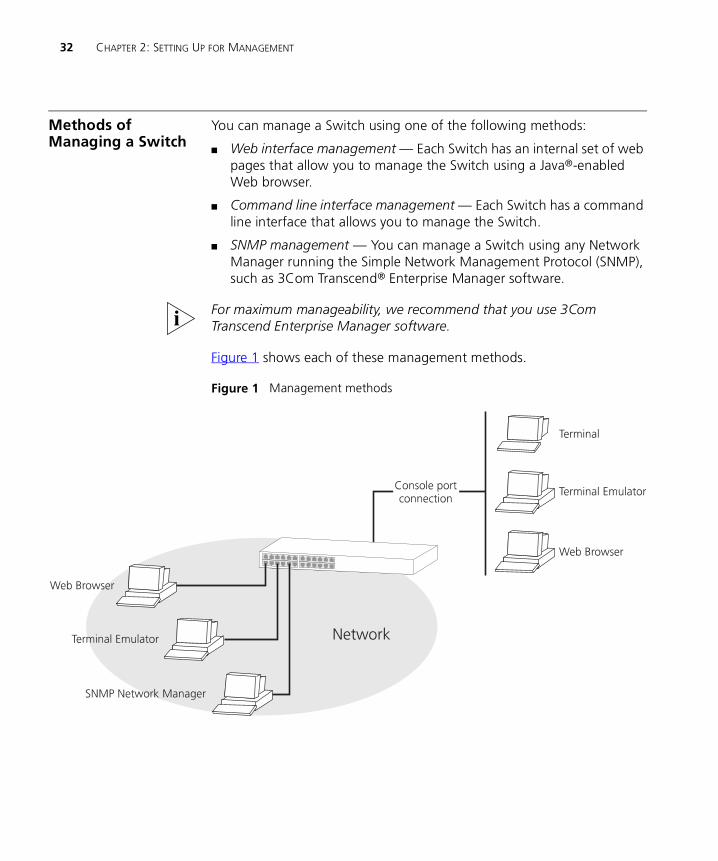
Figure 1 shows each of these management methods.
Figure 1 Management methods
Setting Up Web Interface Management 33
Setting Up Web Interface Management
You can access the web interface using:
� A management workstation connected to the console port of a Switch, running the Serial Line Internet Protocol (SLIP).
� A management workstation connected to a Switch over an IP network.
While multiple users can access the web interface at any one time, too many users may result in a slow response time for the web pages and the error message “document contains no data”. We therefore recommend that you allow only three users access to the interface at any one time.
Setting Up Throughthe Console Port
To manage a Switch using the web interface through the consoleport:
1 You must connect the management workstation to the console port directly using a standard null modem cable. The console port of the Switch has a male 9-pin d-type connector. You can find a pin-out diagram for the cable in your Switch User Guide.
To connect the cable:
a Attach the female connector on the cable to the male connector on the console port of the Switch.
b Tighten the retaining screws on the cable to prevent it from being loosened.
c Connect the other end of the cable to your management workstation.
2 The management workstation must be running the Serial Line Interface Protocol (SLIP), and the SLIP parameters (address and subnet mask) of the Switch need to be configured correctly. To do this, you must install, configure and run the Serial Web Utility described in “Serial Web Utility” on page 227.
3 Install the online help and online documentation for the web interface, if required. For more information, see “Installing Online Help and Documentation” on page 34.
4 Access the web interface using the correct user name and password. Default user names and passwords are described in “Logging in as a Default User” on page 39.
34 CHAPTER 2: SETTING UP FOR MANAGEMENT
Setting Up Over theNetwork
To manage a Switch using the web interface over an IP network:
1 You must set up the Switch with IP information. To do this:
a Access the web interface of the Switch through the console port. See “Setting Up Through the Console Port” on page 33.
b Use the Getting Started pages or IP Setup page to enter suitable IP information for the Switch.
For more information about IP, see “Managing a Switch Over the Network” on page 38. For more information about the Getting Started pages, see “The Getting Started Pages” on page 46. For more information about the IP Setup page, see “Setting Up IP Information” on page 58.
2 You must have an IP stack correctly installed on your management workstation. You can check this by trying to browse the World Wide Web; if you can browse, an IP stack is installed.
3 Your management workstation must be connected to the Switch using a port that is in VLAN 1 (the Default VLAN). By default, all ports on the Switch are in VLAN 1. For more information about VLANs, see “Virtual LANs (VLANs)” on page 163.
Installing Online Helpand Documentation
The CD-ROM supplied with your Switch contains online help and online documentation that can be used with the web interface:
� The online help system provides information for units in the Switch family, and is in HTML (HyperText Markup Language) format.
� The online documentation comprises:
� This Management Guide
� User Guides of all units in the Switch family
All the online documentation is in HTML and PDF (Portable Document Format).
To set up the online help and documentation:
1 Decide where the files are to be stored:
� On a local drive of your management workstation (recommended)
� On the CD-ROM, inserted into the CD-ROM drive of your management workstation
� On a network server
Setting Up Web Interface Management 35
� On the CD-ROM, inserted into the CD-ROM drive of a networked CD-ROM server
� On a Web server
If several users are using the web interface, we recommend that you copy the files onto a server, or insert the CD-ROM into a networked CD-ROM server.
2 If the files are to be accessed from the CD-ROM, insert the CD-ROM into the relevant CD-ROM drive.
3 If the files are to be accessed from a local drive or server, copy the files from the CD-ROM to the relevant directory:
� The help files are stored in the /help directory on the CD-ROM. The help files are accessed using the index.htm file.
� The documentation files are stored in the /docs directory on the CD-ROM. All versions of the documentation are accessed using the index.htm file.
We recommend that you copy the /help and the /docs directory as a whole to maintain the structure of the files.
CAUTION: When entering file paths and URLs, ensure that you use / characters rather than \ characters to define drives and directories. The web interface only understands UNIX file path conventions.
Choosing a Browser To display the web interface correctly, you must use a Web browser that supports:
� Java
� Frames
� HTML 3.2
Suitable Web browsers are:
� Netscape Navigator Version 3.xx and 4.xx
� Microsoft Internet Explorer Version 3.0 or above
Configuring theBrowser
For an optimal display of the web interface, we recommend that you configure your Web browser to use the Times 12pt or Times New Roman 12pt font by default.
36 CHAPTER 2: SETTING UP FOR MANAGEMENT
Setting Up Command Line Interface Management
You can access the command line interface using:
� A terminal or terminal emulator connected to the console port of a Switch directly, or through a modem
� A terminal or terminal emulator connected to a Switch over an IP network using Telnet
Setting Up Throughthe Console Port
To manage a Switch using the command line interface through the console port:
1 You must connect the terminal or terminal emulator to the console port correctly. If you are connecting directly to the console port, you need a standard null modem cable. If you are connecting to the console port using a modem, you need a standard modem cable. The console port of the Switch has a male 9-pin d-type connector. You can find pin-out diagrams for both cables in your Switch User Guide.
To connect the cable:
a Attach the female connector on the cable to the male connector on the console port of the Switch.
b Tighten the retaining screws on the cable to prevent it from being loosened.
c Connect the other end of the cable to your terminal, terminal emulator, or modem.
2 The terminal, terminal emulator, or modem must use the same settings as the console port:
� 8 data bits
� no parity
� 1 stop bit
To configure the settings of the terminal, terminal emulator, or modem, see the documentation that accompanies it. If the Switch containing the console port has auto-configuration enabled (default), the line speed (baud) is detected automatically. The Switch can auto-detect a maximum line speed of 19,200 baud.
3 Access the command line interface using the correct user name and password. Default user names and passwords are described in “Logging in as a Default User” on page 39.

Setting Up SNMP Management 37
Setting Up Over theNetwork
To manage a Switch using the command line interface over a network using Telnet:
1 You must set up the Switch with IP information. To do this:
a Access the command line interface of the Switch through the console port. See “Setting Up Through the Console Port” on page 36.
b Use the ip interface define command to enter suitable IP information for the Switch.
For more information about IP, see “Managing a Switch Over the Network” on page 38. For more information about the ip interface define command, see “Specifying IP and SLIP Information” on page 134.
2 If you are using a terminal emulator, you must have an IP stack correctly installed on the terminal emulator.
3 Your terminal or terminal emulator must be connected to the Switch using a port that is in VLAN 1 (the Default VLAN). By default, all ports on the Switch are in VLAN 1. For more information about VLANs, see “Virtual LANs (VLANs)” on page 163.
4 To open the Telnet session, you must specify the IP address of the Switch. Check the documentation supplied with the Telnet facility if you are unsure how to do this.
Setting Up SNMP Management
Any network management application running the Simple Network Management Protocol (SNMP) can manage a Switch if:
� The correct MIBs (Management Information Bases) are installed on the management workstation
� The management workstation is connected to the Switch using a port in VLAN 1 (the Default VLAN). By default, all ports on the Switch are in VLAN 1. For more information about VLANs, see “Virtual LANs (VLANs)” on page 163.
For information about using an SNMP network management application to manage a Switch, see the documentation supplied with the software.
To manage your Switch using an SNMP network management application, you need to specify SNMP community strings for the users defined on the Switch. You can do this using the command line interface — see “Specifying SNMP Community Strings” on page 137.
38 CHAPTER 2: SETTING UP FOR MANAGEMENT
Managing a Switch Over the Network
When managing a Switch over the network, the Switch must be correctly configured with the following IP information:
� An IP address — for more information, see “IP Addresses” on page 38.
� A subnet mask — for more information, see “Subnets and Using a Subnet Mask” on page 39.
IP Addresses If you are uncertain about what IP addresses to assign your equipment, contact your network administrator.
To operate correctly, each device on your network (for example a hub or management station) must have a unique IP address (if one is configured). IP addresses have the format n.n.n.n where n is a decimal number between 0 and 255. An example IP address is ‘192.168.100.8’.
The IP address can be split into two parts:
� The first part (‘192.168’ in the example) identifies the network on which the device resides.
� The second part (‘100.8’ in the example) identifies the device within the network.
If your network is internal to your organization only, you may use any arbitrary IP address. We suggest you use addresses in the series 192.168.100.X (where X is a number between 1 and 254) with a subnet mask 255.255.255.0. Use the default SLIP address of 192.168.101.1 with a subnet mask of 255.255.255.0.
These suggested IP addresses are part of a group of IP addresses that have been set aside specially for use “in house” only.
CAUTION: If your network has a connection to the external IP network, you must apply for a registered IP address. This system ensures that every IP address used is unique; if you do not have a registered IP address, you may be using an identical address to someone else and your network will not operate correctly.
Obtaining a Registered IP Address
InterNIC Registration Services is the organization responsible for supplying registered IP addresses. The following contact information is correct at time of publication:
Logging in as a Default User 39
World Wide Web site: http://www.internic.net
Subnets and Using aSubnet Mask
You can divide your IP network into sub-networks or subnets. Support for subnets is important because the number of bits assigned to the device part of an IP address limits the number of devices that may be addressed on any given network. For example, a Class C address is restricted to 254 devices.
If you have a small network (less than 254 devices), you may decide not to have subnets.
A subnet mask is used to divide the device part of the IP address into two further parts:
� The first part identifies the subnet number.
� The second part identifies the device on that subnet.
The bits of the subnet mask are set to 1 if the device is to treat the corresponding bit in the IP address as part of the original network number or as part of the subnet number. These bits in the mask are set to 0 if the device is to treat the bit as part of the device number.
If you are unsure about what mask to use, we suggest that you use a general mask, 255.255.255.0, which corresponds to the example address used in the previous sections.
Logging in as a Default User
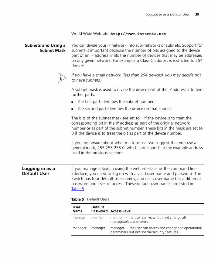
If you manage a Switch using the web interface or the command line interface, you need to log on with a valid user name and password. The Switch has four default user names, and each user name has a different password and level of access. These default user names are listed in Table 5.
Table 5 Default Users
User Name
DefaultPassword Access Level
monitor monitor monitor — the user can view, but not change all manageable parameters
manager manager manager — the user can access and change the operational parameters but not special/security features
40 CHAPTER 2: SETTING UP FOR MANAGEMENT
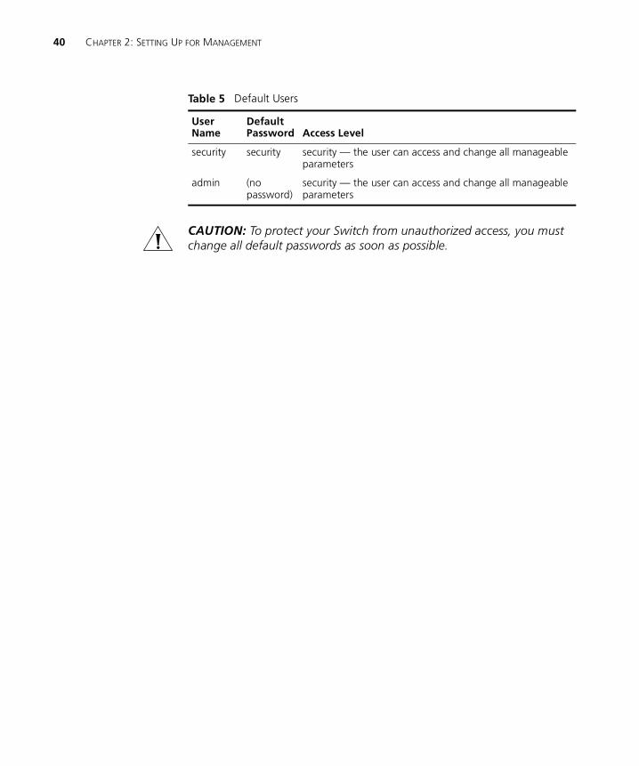
CAUTION: To protect your Switch from unauthorized access, you must change all default passwords as soon as possible.
security security security — the user can access and change all manageable parameters
admin (no password)
security — the user can access and change all manageable parameters
Table 5 Default Users
User Name
DefaultPassword Access Level

II
THE MANAGEMENT INTERFACESChapter 3 Working With the Web Interface
Chapter 4 Working With the Command Line Interface


3
WORKING WITH THE WEB INTERFACEThis chapter describes how to access and use the web interface. It covers the following topics:
� Accessing the Web Interface
� The Getting Started Pages
� The Main Web Interface
� Configuring the Current Switch
� Changing the Management Settings for the Stack
� Configuring the Stack
� Displaying Statistics for the Current Switch
Throughout this chapter, the term stack refers to a number of Switch units that are managed as a single unit. However, a stack can contain a single Switch.
44 CHAPTER 3: WORKING WITH THE WEB INTERFACE
Accessing the Web Interface
You can access the web interface through the console port or over the network.
To access the web interface through the console port, you must install, configure and run the Serial Web Utility described in “Serial Web Utility” on page 227. Note that the Serial Web Utility is only required if you want to access the web interface through the console port; it is not required for access over the network.
To access the web interface over the network, take the following steps:
1 Ensure that your network is correctly set up for management using the web interface. For more information, see “Setting Up Web Interface Management” on page 33.
2 Open your Web browser.
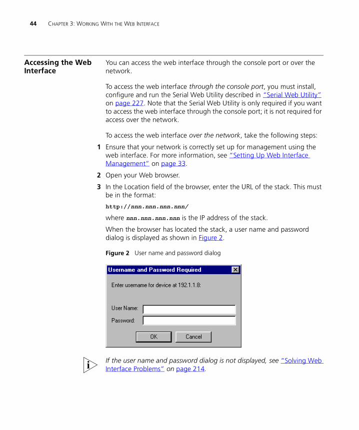
3 In the Location field of the browser, enter the URL of the stack. This must be in the format:
http://nnn.nnn.nnn.nnn/
where nnn.nnn.nnn.nnn is the IP address of the stack.
When the browser has located the stack, a user name and password dialog is displayed as shown in Figure 2.
Figure 2 User name and password dialog
If the user name and password dialog is not displayed, see “Solving Web Interface Problems” on page 214.
Accessing the Web Interface 45
4 Enter your user name and password:
� If you have been assigned a user name and password, enter those details.
� If you are accessing the web interface for the first time, enter a default user name and password to match your access requirements. The defaults are described in “Logging in as a Default User” on page 39. If you are setting up the stack for management, we suggest that you log on as admin (which has no default password).
To prevent unauthorized configuration of the stack, we recommend that you change the default passwords as soon as possible. To do this using the web interface, you need to log in as each default user and then follow the steps described in “Changing Your Password” on page 68.
If you forget your password while logged out of the web interface, see “Solving Web Interface Problems” on page 214.
Once you have entered a correct user name and password, one of two events occur:
� If you are accessing the web interface for the first time, a set of Getting Started pages are displayed. These are described in “The Getting Started Pages” on page 46.
� If you have accessed the web interface before, the main web interface is displayed. For information about the interface, see “The Main Web Interface” on page 48.
If you are unable to access the web interface, see “Solving Web Interface Problems” on page 214.
CAUTION: While multiple users can access the web interface at any one time, too many users may result in a slow response time for the web pages and the error message “document contains no data”. We therefore recommend that you allow only three users to access the interface at any one time.
While you are managing the stack, you can display other web pages using your browser, and then simply use the Back button to reload the web management pages. You do not need to re-enter your username and password.
Exiting the WebInterface
You can exit the web interface at any time; to do this, close your Web browser. For security reasons, you should always close your Web browser after a management session.
46 CHAPTER 3: WORKING WITH THE WEB INTERFACE
The Getting Started Pages
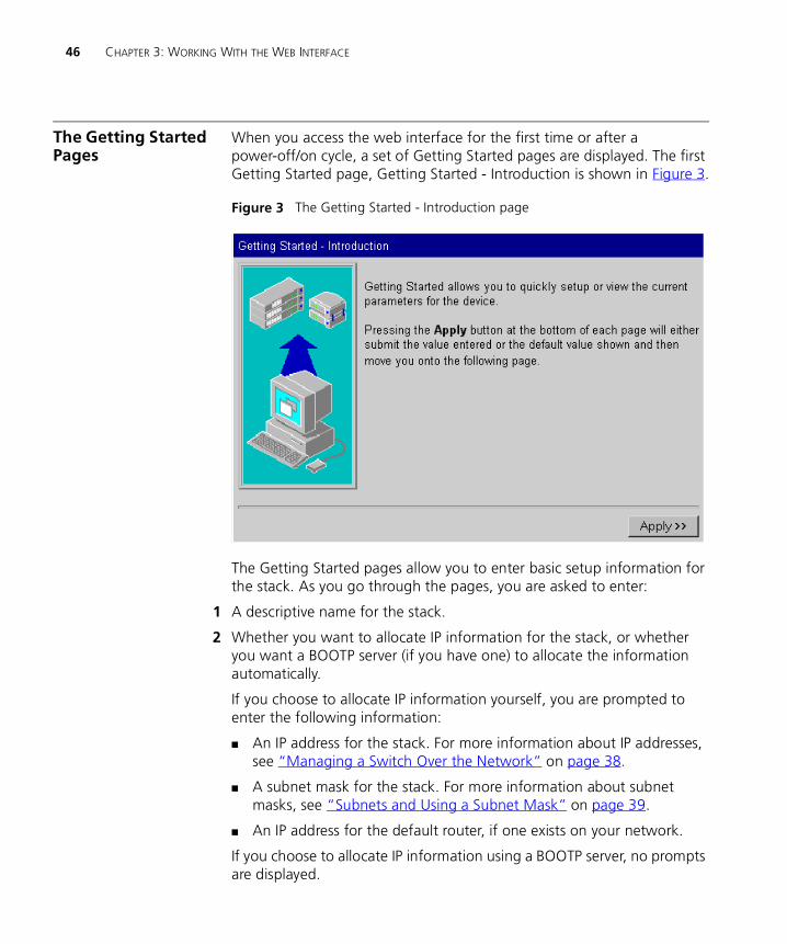
When you access the web interface for the first time or after a power-off/on cycle, a set of Getting Started pages are displayed. The first Getting Started page, Getting Started - Introduction is shown in Figure 3.
Figure 3 The Getting Started - Introduction page
The Getting Started pages allow you to enter basic setup information for the stack. As you go through the pages, you are asked to enter:
1 A descriptive name for the stack.
2 Whether you want to allocate IP information for the stack, or whether you want a BOOTP server (if you have one) to allocate the information automatically.
If you choose to allocate IP information yourself, you are prompted to enter the following information:
� An IP address for the stack. For more information about IP addresses, see “Managing a Switch Over the Network” on page 38.
� A subnet mask for the stack. For more information about subnet masks, see “Subnets and Using a Subnet Mask” on page 39.
� An IP address for the default router, if one exists on your network.
If you choose to allocate IP information using a BOOTP server, no prompts are displayed.
The Getting Started Pages 47
3 The URL or file path of the online help and online documentation for the stack.
� If the files are installed on your management workstation, on the CD-ROM, or on a network server, you must begin the file path with file://
� If the files are stored on a Web server, you must begin the URL with http://
If you do not know where the online help and online documentation is stored, see “Installing Online Help and Documentation” on page 34.
4 A new password for the current user (enter the existing password if you want to leave the password unchanged).
Once you have completed the Getting Started pages, the main web interface is displayed. For information about the interface, see “The Main Web Interface” on page 48.
The Getting Started pages are available from the main web interface at any time. For more information, see “Changing the Management Settings for the Stack” on page 67.
48 CHAPTER 3: WORKING WITH THE WEB INTERFACE
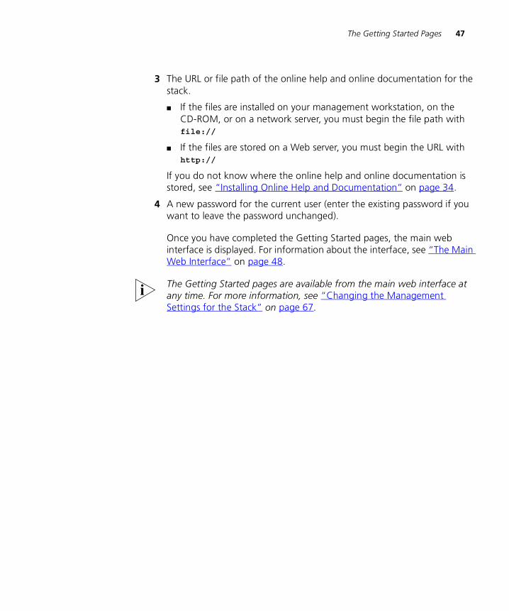
The Main Web Interface
The main web interface is made up of three areas:
� The Banner
This is always displayed at the top of the browser window. It displays the name of the current Switch in the stack, and contains several External Link icons that allow you to access information outside of the web interface. For more information about the External Links, see “The External Link Icons” on page 49.
� The Side-bar
This is always displayed down the left side of the browser window. It contains Management Icons that allow you to display web pages in the page area (below). For more information, see “The Management Icons” on page 50.
� The Page Area
This is always displayed in the center of the browser window. It contains the various web pages that allow you to manage the stack. For more information, see “The Page Area” on page 50.
Figure 4 Parts of the main web interface
The Main Web Interface 49
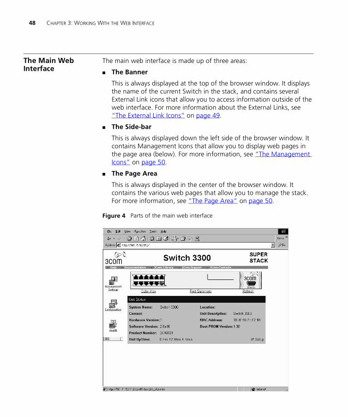
The External LinkIcons
The banner of the main web interface contains several External Link icons that allow you to access information outside of the interface; these are shown in Table 6.
Table 6 External Link icons and their actions
External Link Icon Action
If your management workstation has access to the World Wide Web, clicking the 3Com icon displays the home page of the 3Com World Wide Web site in a second browser window.
If you have set up the online help, clicking the Help icon displays the help for the web interface in a second browser window.
For information about setting up the online help, see “Installing Online Help and Documentation” on page 34.
If you have set up the online documentation, clicking the Documentation icon allows you to access the User Guides and Management Guide for the stack in a second browser window.
For information about setting up the online documentation, see “Installing Online Help and Documentation” on page 34.
If your management workstation has access to the World Wide Web, clicking the 3Com Library icon displays the Online Library of the 3Com World Wide Web site in a second browser window.
If your management workstation has access to the World Wide Web, clicking the 3Com Support icon displays support information from the 3Com World Wide Web site in a second browser window.
If your management workstation has access to the World Wide Web, clicking the 3Com Contacts icon displays contact information from the 3Com World Wide Web site in a second browser window.
50 CHAPTER 3: WORKING WITH THE WEB INTERFACE
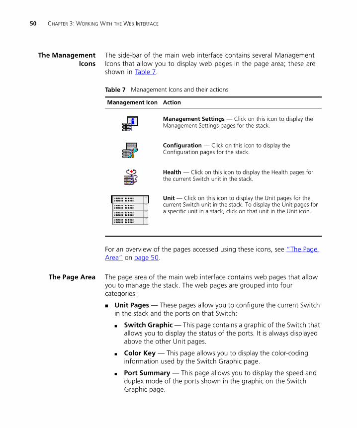
The ManagementIcons
The side-bar of the main web interface contains several Management Icons that allow you to display web pages in the page area; these are shown in Table 7.
For an overview of the pages accessed using these icons, see “The Page Area” on page 50.
The Page Area The page area of the main web interface contains web pages that allow you to manage the stack. The web pages are grouped into four categories:
� Unit Pages — These pages allow you to configure the current Switch in the stack and the ports on that Switch:
� Switch Graphic — This page contains a graphic of the Switch that allows you to display the status of the ports. It is always displayed above the other Unit pages.
� Color Key — This page allows you to display the color-coding information used by the Switch Graphic page.
� Port Summary — This page allows you to display the speed and duplex mode of the ports shown in the graphic on the Switch Graphic page.
Table 7 Management Icons and their actions
Management Icon Action
Management Settings — Click on this icon to display the Management Settings pages for the stack.
Configuration — Click on this icon to display the Configuration pages for the stack.
Health — Click on this icon to display the Health pages for the current Switch unit in the stack.
Unit — Click on this icon to display the Unit pages for the current Switch unit in the stack. To display the Unit pages for a specific unit in a stack, click on that unit in the Unit icon.
The Main Web Interface 51
� Unit Status — This page allows you to display the general administration details of the Switch.
� IP Setup — This page allows you to set up IP information for the Switch.
� Port Setup — This page allows you to configure individual ports on the Switch.
� Console Port Configuration — This page allows you to configure the console port of the Switch.
For more information, see “Configuring the Current Switch” on page 54.
� Management Settings Pages — These pages allow you to change the management settings for the stack:
� System Name — This page allows you to specify a descriptive name for the stack.
� Password Setting — This page allows you to change your password.
� Location — This page allows you to specify the physical location of the stack.
� Getting Started — This page allows you to access the Getting Started pages for the stack.
� Documentation — This page allows you to specify the location of the online help and documentation for the stack.
� Contact — This page allows you to specify the details of a person to contact about the stack.
For more information, see “Changing the Management Settings for the Stack” on page 67.
� Configuration Pages — These pages allow you to configure the stack as a whole:
� VLAN Setup — This page allows you to configure VLANs for the stack.
� Switch Database — This page allows you to configure the Switch Database of the stack.
� Software Upgrade — This page allows you to upgrade the management software of the Switch units in the stack.
52 CHAPTER 3: WORKING WITH THE WEB INTERFACE
� Roving Analysis Setup — This page allows you to set up roving analysis ports for the stack.
� Resilient Links — This page allows you to set up resilient links for the stack.
� Reset — This page allows you to reset the Switch units in the stack.
� Port Trunks Setup — This page allows you to set up port trunks for the stack.
� Initialize — This page allows you to initialize the Switch units in the stack.
� Advanced Stack Setup — This page allows you to configure the advanced settings of the stack.
For more information, see “Configuring the Stack” on page 71.
� Health Pages — These pages allow you to display statistics for the current Switch in the stack:
� Unit Graph — This page allows you to display a range of statistics for all the ports on the Switch.
� Port Graph — This page allows you to display a range of statistics for a specific port on the Switch.
For more information, see “Displaying Statistics for the Current Switch” on page 91.
Navigating the Page Area
To access the first page of each category, click on the relevant Management Icon on the side-bar; to access the remaining pages in the category, click on the underlined hotlinks that are displayed at the top of each page.
There are four exceptions to the navigation system. The Color Key page, Port Summary page, Port Setup page and Console Port Configuration page are accessed from the Switch Graphic page.
Figure 5 shows you how to access each of the web pages.
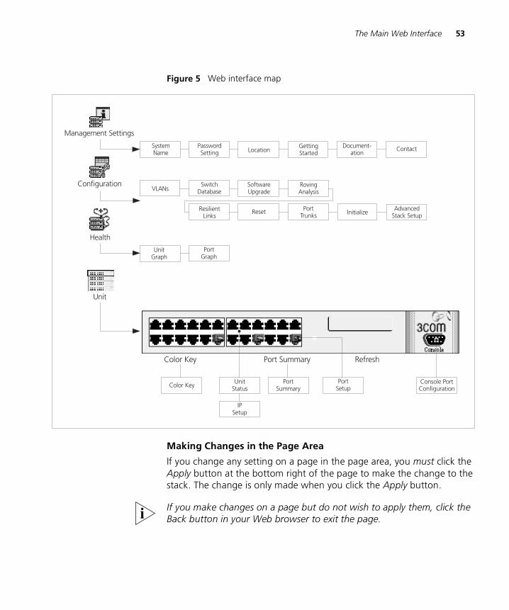
The Main Web Interface 53
Figure 5 Web interface map
Making Changes in the Page Area
If you change any setting on a page in the page area, you must click the Apply button at the bottom right of the page to make the change to the stack. The change is only made when you click the Apply button.
If you make changes on a page but do not wish to apply them, click the Back button in your Web browser to exit the page.
54 CHAPTER 3: WORKING WITH THE WEB INTERFACE
Configuring the Current Switch
You can configure the current Switch and the ports on that Switch using the Unit Pages. These pages allow you to:
� Display the status of the ports on the Switch
� Display the general administration details of the Switch
� Set up IP information for the Switch
� Configure individual ports on the Switch
� Configure the console port of the Switch
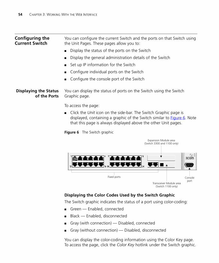
Displaying the Statusof the Ports
You can display the status of ports on the Switch using the Switch Graphic page.
To access the page:
� Click the Unit icon on the side-bar. The Switch Graphic page is displayed, containing a graphic of the Switch similar to Figure 6. Note that this page is always displayed above the other Unit pages.
Figure 6 The Switch graphic
Displaying the Color Codes Used by the Switch Graphic
The Switch graphic indicates the status of a port using color-coding:
� Green — Enabled, connected
� Black — Enabled, disconnected
� Gray (with connection) — Disabled, connected
� Gray (without connection) — Disabled, disconnected
You can display the color-coding information using the Color Key page. To access the page, click the Color Key hotlink under the Switch graphic.
Configuring the Current Switch 55
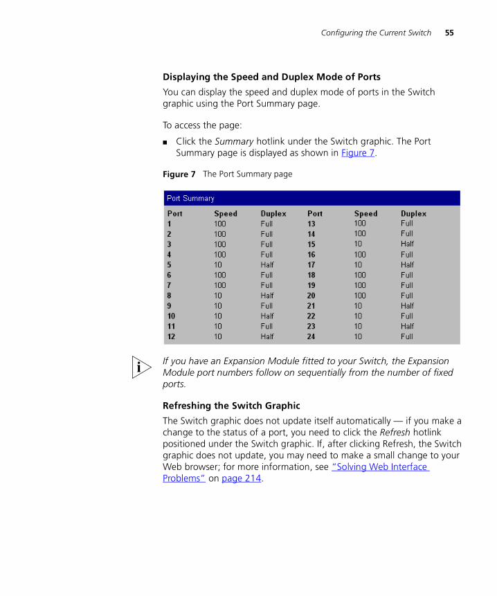
Displaying the Speed and Duplex Mode of Ports
You can display the speed and duplex mode of ports in the Switch graphic using the Port Summary page.
To access the page:
� Click the Summary hotlink under the Switch graphic. The Port Summary page is displayed as shown in Figure 7.
Figure 7 The Port Summary page
If you have an Expansion Module fitted to your Switch, the Expansion Module port numbers follow on sequentially from the number of fixed ports.
Refreshing the Switch Graphic
The Switch graphic does not update itself automatically — if you make a change to the status of a port, you need to click the Refresh hotlink positioned under the Switch graphic. If, after clicking Refresh, the Switch graphic does not update, you may need to make a small change to your Web browser; for more information, see “Solving Web Interface Problems” on page 214.
56 CHAPTER 3: WORKING WITH THE WEB INTERFACE
DisplayingAdministration
Details
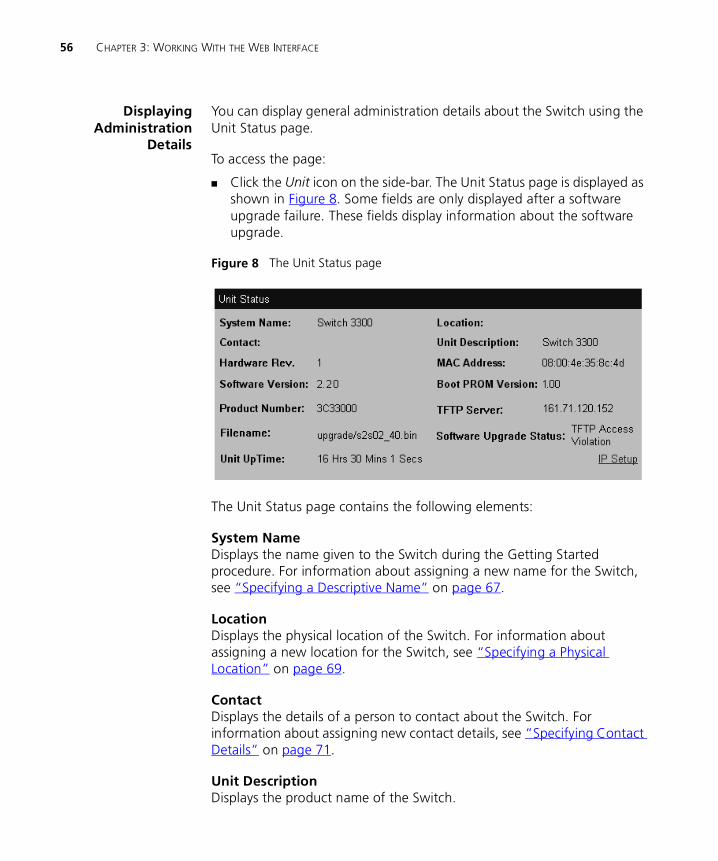
You can display general administration details about the Switch using the Unit Status page.
To access the page:
� Click the Unit icon on the side-bar. The Unit Status page is displayed as shown in Figure 8. Some fields are only displayed after a software upgrade failure. These fields display information about the software upgrade.
Figure 8 The Unit Status page
The Unit Status page contains the following elements:
System NameDisplays the name given to the Switch during the Getting Started procedure. For information about assigning a new name for the Switch, see “Specifying a Descriptive Name” on page 67.
LocationDisplays the physical location of the Switch. For information about assigning a new location for the Switch, see “Specifying a Physical Location” on page 69.
ContactDisplays the details of a person to contact about the Switch. For information about assigning new contact details, see “Specifying Contact Details” on page 71.
Unit DescriptionDisplays the product name of the Switch.
Configuring the Current Switch 57
Hardware RevDisplays the version number of the Switch hardware.
MAC AddressDisplays the MAC (Ethernet) address assigned to the Switch.
Software VersionDisplays the version number of the management software currently installed on the Switch. For information about how to upgrade the management software, see “Upgrading Management Software” on page 89.
Boot PROM VersionDisplays the version of Boot PROM software installed on the Switch.
Product NumberDisplays the 3Com product number of the unit.
TFTP Server (optionally displayed)Displays the IP address of the last TFTP server used to upgrade the unit’s management software.
Filename (optionally displayed)Displays the name of the management software file that was used during the last software upgrade attempt.
Software Upgrade Status (optionally displayed)Displays the reason for a software upgrade failure.
Unit UptimeDisplays the time that has elapsed since the Switch was last reset, initialized or powered-up.
58 CHAPTER 3: WORKING WITH THE WEB INTERFACE
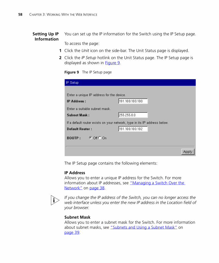
Setting Up IPInformation
You can set up the IP information for the Switch using the IP Setup page.
To access the page:
1 Click the Unit icon on the side-bar. The Unit Status page is displayed.
2 Click the IP Setup hotlink on the Unit Status page. The IP Setup page is displayed as shown in Figure 9.
Figure 9 The IP Setup page
The IP Setup page contains the following elements:
IP AddressAllows you to enter a unique IP address for the Switch. For more information about IP addresses, see “Managing a Switch Over the Network” on page 38.
If you change the IP address of the Switch, you can no longer access the web interface unless you enter the new IP address in the Location field of your browser.
Subnet MaskAllows you to enter a subnet mask for the Switch. For more information about subnet masks, see “Subnets and Using a Subnet Mask” on page 39.
Configuring the Current Switch 59
Default RouterIf your network contains one or more routers, this field allows you to enter the IP address of the default router. For more information about IP addresses, see “Managing a Switch Over the Network” on page 38.
BOOTP On / OffIf you have a BOOTP server on your network, these radio buttons allow you to specify whether the server allocates IP information for the Switch automatically.
For BOOTP to work correctly, the Switch must have the IP address 0.0.0.0. If the Switch has another IP address, you must change the address to 0.0.0.0 and then reset the Switch.
The Switch only requests IP information from the BOOTP server 12 times. If the Switch has not received the information by the 12th time, you must reset the Switch and start again.
After BOOTP is enabled, you need to power cycle the unit before BOOTP starts operating
Configuring a Port You can configure individual ports on the Switch using the Port Setup page.
To access the page:
1 Click the Unit icon on the side-bar.
2 Click the relevant port on the Switch graphic. The Port Setup page is displayed as shown in Figure 10 or Figure 11.
60 CHAPTER 3: WORKING WITH THE WEB INTERFACE
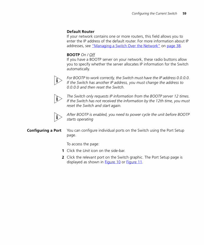
Figure 10 The Port Setup page with auto-negotiation enabled
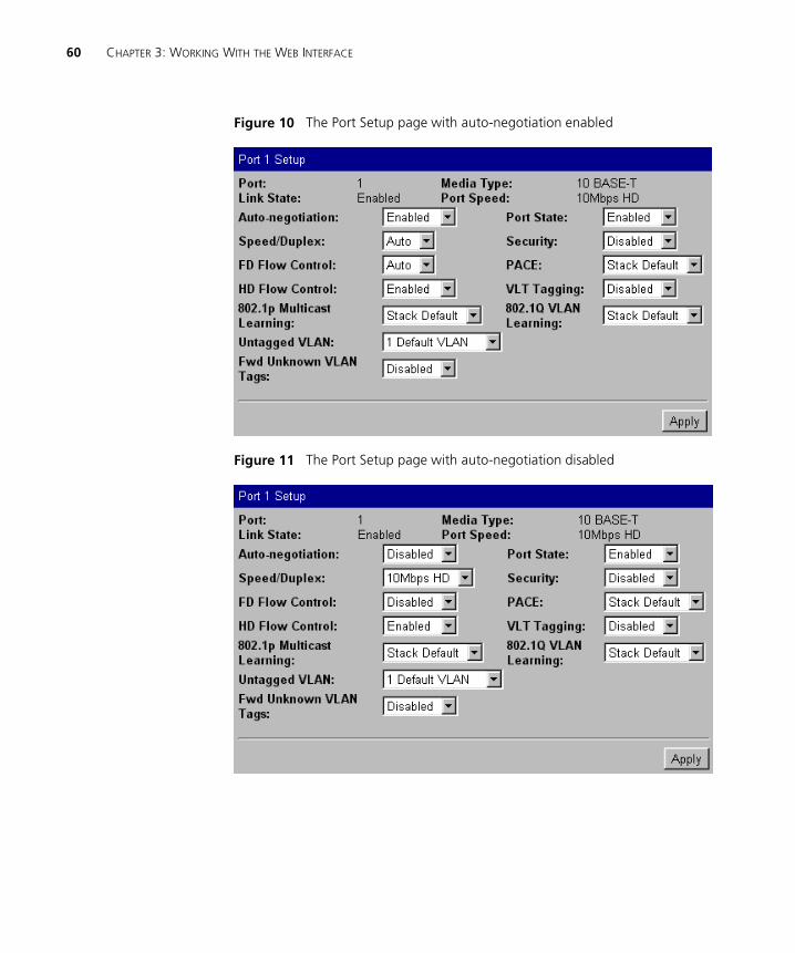
Figure 11 The Port Setup page with auto-negotiation disabled
Configuring the Current Switch 61
The Port Setup page contains the following elements:
PortDisplays the number of the selected port.
Link State Enabled / DisabledDisplays the state of the link connected to the port.
Media TypeDisplays the media type of the link connected to the port.
Port SpeedDisplays the current speed and duplex mode of the port. FC indicates that flow control is enabled.
Auto-negotiation Enabled / DisabledAllows you to specify whether auto-negotiation is enabled for twisted pair ports:
� If auto-negotiation is enabled on a 10BASE-T/100BASE-TX port, the speed and duplex mode of the link is automatically detected and set accordingly. (See the note below headed Switch 610 and Switch 1100.)
� If auto-negotiation is enabled on a 10BASE-T port, the duplex mode of the link is automatically detected and set accordingly.
� If auto-negotiation is disabled, the speed and duplex mode of the port is set using the Speed/Duplex listbox.
CAUTION: The duplex mode of a link is not detected if the port on the other end of the link is not auto-negotiating. In this case, the Switch port is set to operate in half duplex:
� If you want the link to operate in full duplex, set the Switch port to operate in full duplex using the Speed/Duplex listbox.
� If you want the link to operate in half duplex, set the port on the other end of the link to half duplex.
Fiber ports and Transceiver Module ports are not auto-negotiating. If the port is one of these ports, the Auto-negotiation listbox is set to Disabled and you cannot change it.
With auto-negotiation enabled, the Speed/Duplex listbox and Full Duplex Flow Control listbox display Auto and cannot be set manually.
62 CHAPTER 3: WORKING WITH THE WEB INTERFACE
Switch 610 and Switch 1100 only. The 10BASE-T/100BASE-TX ports on the Switch 1100 cannot auto-negotiate IEEE802.3x flow control. Follow the instructions below to enable flow control on the Switch 1100 10BASE-T/100BASETX ports.
To enable flow control on the Switch 1100 10BASE-T/100BASE-TX ports:
1 From the Port Setup page, set the Auto-Negotiation listbox to disabled.
2 Click Apply.
3 Set the FD Flow Control listbox to Enabled.
4 Configure the port to the desired speed and full duplex operation.
5 Click Apply.
Speed/Duplex 100Mbps FD / 100Mbps HD / 10Mbps FD / 10Mbps HD / AutoIf the port does not support auto-negotiation, or if auto-negotiation is disabled, this listbox allows you to:
� Specify the speed and duplex mode of 10BASE-T/100BASE-TX ports (HD indicates half duplex, FD indicates full duplex).
� Specify the duplex mode of 10BASE-T and 100BASE-FX ports.
If auto-negotiation is enabled, the listbox displays Auto and you cannot change the speed or duplex mode of the port manually.
CAUTION: To communicate without errors, both ends of a link must use the same duplex mode.
FD Flow Control Enabled / Disabled / AutoIf auto-negotiation is disabled, this listbox allows you to enable or disable the IEEE 802.3x flow control that can be used when the port is operating in full duplex. If auto-negotiation is enabled, the listbox displays Auto, and you cannot change the flow control setting for the port manually. Flow control prevents any packet loss that may occur on congested ports.
For IEEE 802.3x flow control to operate correctly, it must be enabled at both ends of the link.
Configuring the Current Switch 63
HD Flow Control Enabled / DisabledAllows you to enable or disable the Intelligent Flow Management flow control that can be used when the port is operating in half duplex. Flow control prevents any packet loss that may occur on congested ports.
The Half Duplex Flow Control listbox should be disabled if the port is connected to multiple devices using a hub. If it is enabled, local traffic between those multiple devices is inhibited.
802.1p Multicast Learning Stack Default / DisabledAllows you to specify whether the port uses IEEE 802.1p multicast filtering (GMRP) to filter and forward multicasts automatically:
� Stack Default — The port takes the 802.1p multicast learning setting from the Advanced Stack Setup page. For more information, see “Configuring the Advanced Stack Settings” on page 76.
� Disabled — The port does not use IEEE 802.1p multicast filtering. Use this setting if the device at the other end of the link does not support IEEE 802.1p.
For more information about IEEE 802.1p multicast filtering, see “Multicast Filtering” on page 189.
Untagged VLANAllows you to specify a single VLAN to which the port belongs. For more information about VLANs, see “Virtual LANs (VLANs)” on page 163.
If you want to move a port from the Default VLAN (VLAN 1) to another VLAN, that VLAN must have information defined for it. If you select a VLAN in the Untagged VLAN listbox that does not have information defined for it (that is, one that has the description Unassigned) and you then click the Apply button, the Create VLAN page is displayed allowing you to enter information for that VLAN. Once you have entered the VLAN information, the Port Setup page is re-displayed and the port is placed in the VLAN. For information about the Create VLAN page, see “Defining VLAN Information” on page 84.
If the port at the other end of the link supports VLT or 802.1Q tagging, you can specify that the port belongs to multiple VLANs. To specify that the port belongs to multiple VLANs using VLT tagging, set the VLT Tagging listbox to Enable. To specify that the port belongs to multiple VLANs using 802.1Q tagging, see “Placing a Port in Multiple VLANs” on page 166.
64 CHAPTER 3: WORKING WITH THE WEB INTERFACE
FWD Unknown VLAN Tags Enabled / Disabled / AutoAllows you to specify whether the port forwards traffic that uses unknown IEEE 802.1Q tags. If 802.1Q VLAN learning is disabled, you can specify:
� Enabled — Use this setting if the port is connected to a switch that supports IEEE 802.1Q VLANs.
� Disabled — Use this setting if the port is connected to an endstation, hub, bridge, router, or a switch that does not support IEEE 802.1Q VLANs.
If 802.1Q VLAN learning is enabled, you can specify:
� Auto — Use this setting if you want the Switch to automatically organize the forwarding of traffic containing unknown tags.
� Enabled — Use this setting if the port is connected to a switch that supports IEEE 802.1Q VLANs, and you want to override the automatic organization of traffic containing unknown tags.
For more information about forwarding VLAN traffic that uses unknown tags, see “Forwarding Traffic Containing Unknown 802.1Q Tags” on page 168.
Port State Enabled / DisabledAllows you to enable or disable the port (that is, turn the port on or off).
Security Enabled / DisabledAllows you to specify whether the port uses security to guard against unauthorized users connecting devices to your network. When security is enabled on a port, it enters Single Address Learning Mode. In this mode, the Switch:
� Removes all the MAC (Ethernet) addresses stored for the port in the Switch Database.
� Learns the address of the first packet it receives on the port.
� Defines the address as a permanent entry.
Once the first address is learned:
� The port is disabled if a different address is seen on the port.
� No other address can be learned until security is disabled or the address is manually removed from the database.
� The address cannot be learned on another port until security is disabled or the address is manually removed from the database.
Configuring the Current Switch 65
You cannot enable security on a port that is part of a resilient link, or a port that is part of a port trunk. For more information, see “Setting Up Resilient Links” on page 79 and “Port Trunks” on page 157.
PACE Stack Default / Enabled / DisabledAllows you to specify whether the port uses PACE (Priority Access Control Enabled) to support multimedia traffic:
� Stack Default — The port takes the PACE setting from the Advanced Stack Setup page. For more information, see “Configuring the Advanced Stack Settings” on page 76.
� Enabled — Use this setting if the port is connected to:
� A switch, bridge or router that does not support PACE, or has PACE disabled
� An endstation that has PACE enabled
� Disabled — Use this setting if the port is connected to:
� A hub
� A switch, bridge or router that has PACE enabled
� An endstation that does not support PACE, or has PACE disabled
VLT Tagging Enabled / DisabledAllows you specify whether the port uses VLT (Virtual LAN Trunk) tagging. By specifying that the ports at both ends of a link use VLT tagging, you can create a VLT tagged link that carries traffic for all of the VLANs defined on your Switch. For more information about VLT tagging, see “Placing a Port in Multiple VLANs” on page 166.
VLT tagging can only be used on links to legacy 3Com devices.
A port cannot use VLT tagging if:
� It uses 802.1Q tagging — for more information about 802.1Q tagging, see “Placing a Port in Multiple VLANs” on page 166.
� It is the main or standby port of a resilient link, and the other port does not use VLT tagging — for more information about resilient links, see “Setting Up Resilient Links” on page 79.
� It belongs to a port trunk — for more information about port trunks, see “Port Trunks” on page 157.
You cannot disable VLT tagging if the port is part of a resilient link pair.
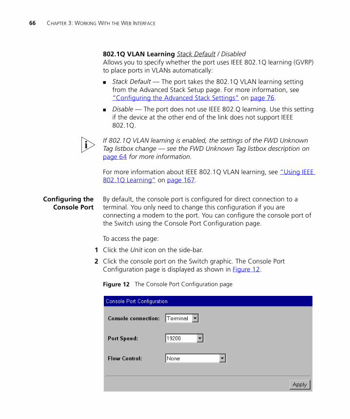
66 CHAPTER 3: WORKING WITH THE WEB INTERFACE
802.1Q VLAN Learning Stack Default / DisabledAllows you to specify whether the port uses IEEE 802.1Q learning (GVRP) to place ports in VLANs automatically:
� Stack Default — The port takes the 802.1Q VLAN learning setting from the Advanced Stack Setup page. For more information, see “Configuring the Advanced Stack Settings” on page 76.
� Disable — The port does not use IEEE 802.Q learning. Use this setting if the device at the other end of the link does not support IEEE 802.1Q.
If 802.1Q VLAN learning is enabled, the settings of the FWD Unknown Tag listbox change — see the FWD Unknown Tag listbox description on page 64 for more information.
For more information about IEEE 802.1Q VLAN learning, see “Using IEEE 802.1Q Learning” on page 167.
Configuring theConsole Port
By default, the console port is configured for direct connection to a terminal. You only need to change this configuration if you are connecting a modem to the port. You can configure the console port of the Switch using the Console Port Configuration page.
To access the page:
1 Click the Unit icon on the side-bar.
2 Click the console port on the Switch graphic. The Console Port Configuration page is displayed as shown in Figure 12.
Figure 12 The Console Port Configuration page
Changing the Management Settings for the Stack 67
The Console Port Configuration page contains the following elements:
Console connection Terminal / ModemAllows you to specify the device that you are connecting to the console port.
Port Speed AutoConfig / 1200 / 2400 / 4800 / 9600 / 19200Allows you to specify the line speed (baud) of the console port. If you select AutoConfig, the line speed of the port is automatically set to the line speed of the terminal or modem.
For the AutoConfig system to work, you need to reset the Switch.
Flow Control None / Hardware RTS/CTSAllows you to specify the serial line flow control option suitable for your terminal or modem. See the documentation accompanying your terminal or modem if you are unsure of the correct setting.
Changing the Management Settings for the Stack
You can change the management settings for the stack using the Management Settings Pages. These pages allow you to:
� Specify a descriptive name for the stack.
� Change your password.
� Specify the physical location of the stack.
� Access the Getting Started pages for the stack.
� Specify the location of the online help and documentation for the stack.
� Specify the details of a person to contact about the stack.
Specifying aDescriptive Name
You can specify a descriptive name for the stack using the System Name page.
To access the page:
1 Click the Management Settings icon on the side-bar.
2 Click the System Name hotlink. The System Name page is displayed as shown in Figure 13.

68 CHAPTER 3: WORKING WITH THE WEB INTERFACE
Figure 13 The System Name page
The Name field allows you to enter a descriptive name for the stack. The name can be up to 20 characters long.
Changing YourPassword
You can change the password for your user using the Password Setting page.
To access the page:
1 Click the Management Settings icon on the side-bar.
2 Click the Password Setting hotlink. The Password Setting page is displayed as shown in Figure 14.
Figure 14 The Password Setting page
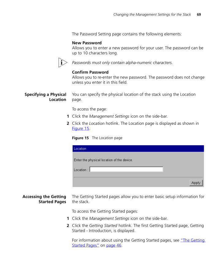
Changing the Management Settings for the Stack 69
The Password Setting page contains the following elements:
New PasswordAllows you to enter a new password for your user. The password can be up to 10 characters long.
Passwords must only contain alpha-numeric characters.
Confirm PasswordAllows you to re-enter the new password. The password does not change unless you enter it in this field.
Specifying a PhysicalLocation
You can specify the physical location of the stack using the Location page.
To access the page:
1 Click the Management Settings icon on the side-bar.
2 Click the Location hotlink. The Location page is displayed as shown in Figure 15.
Figure 15 The Location page
Accessing the GettingStarted Pages
The Getting Started pages allow you to enter basic setup information for the stack.
To access the Getting Started pages:
1 Click the Management Settings icon on the side-bar.
2 Click the Getting Started hotlink. The first Getting Started page, Getting Started - Introduction, is displayed.
For information about using the Getting Started pages, see “The Getting Started Pages” on page 46.
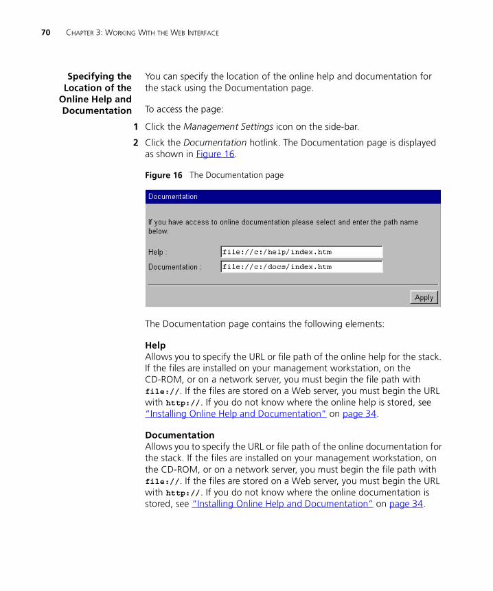
70 CHAPTER 3: WORKING WITH THE WEB INTERFACE
Specifying theLocation of the
Online Help andDocumentation
You can specify the location of the online help and documentation for the stack using the Documentation page.
To access the page:
1 Click the Management Settings icon on the side-bar.
2 Click the Documentation hotlink. The Documentation page is displayed as shown in Figure 16.
Figure 16 The Documentation page
The Documentation page contains the following elements:
HelpAllows you to specify the URL or file path of the online help for the stack. If the files are installed on your management workstation, on the CD-ROM, or on a network server, you must begin the file path with file://. If the files are stored on a Web server, you must begin the URL with http://. If you do not know where the online help is stored, see “Installing Online Help and Documentation” on page 34.
DocumentationAllows you to specify the URL or file path of the online documentation for the stack. If the files are installed on your management workstation, on the CD-ROM, or on a network server, you must begin the file path with file://. If the files are stored on a Web server, you must begin the URL with http://. If you do not know where the online documentation is stored, see “Installing Online Help and Documentation” on page 34.
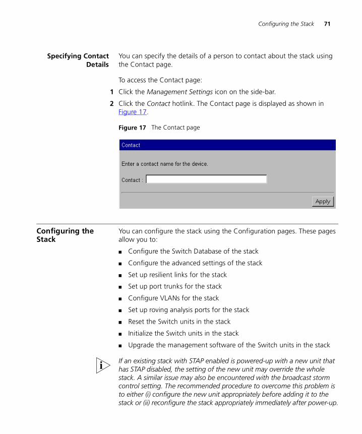
Configuring the Stack 71
Specifying ContactDetails
You can specify the details of a person to contact about the stack using the Contact page.
To access the Contact page:
1 Click the Management Settings icon on the side-bar.
2 Click the Contact hotlink. The Contact page is displayed as shown in Figure 17.
Figure 17 The Contact page
Configuring the Stack
You can configure the stack using the Configuration pages. These pages allow you to:
� Configure the Switch Database of the stack
� Configure the advanced settings of the stack
� Set up resilient links for the stack
� Set up port trunks for the stack
� Configure VLANs for the stack
� Set up roving analysis ports for the stack
� Reset the Switch units in the stack
� Initialize the Switch units in the stack
� Upgrade the management software of the Switch units in the stack
If an existing stack with STAP enabled is powered-up with a new unit that has STAP disabled, the setting of the new unit may override the whole stack. A similar issue may also be encountered with the broadcast storm control setting. The recommended procedure to overcome this problem is to either (i) configure the new unit appropriately before adding it to the stack or (ii) reconfigure the stack appropriately immediately after power-up.
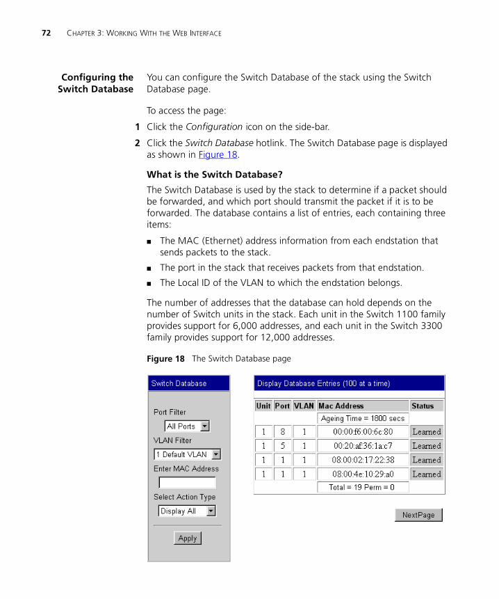
72 CHAPTER 3: WORKING WITH THE WEB INTERFACE
Configuring theSwitch Database
You can configure the Switch Database of the stack using the Switch Database page.
To access the page:
1 Click the Configuration icon on the side-bar.
2 Click the Switch Database hotlink. The Switch Database page is displayed as shown in Figure 18.
What is the Switch Database?
The Switch Database is used by the stack to determine if a packet should be forwarded, and which port should transmit the packet if it is to be forwarded. The database contains a list of entries, each containing three items:
� The MAC (Ethernet) address information from each endstation that sends packets to the stack.
� The port in the stack that receives packets from that endstation.
� The Local ID of the VLAN to which the endstation belongs.
The number of addresses that the database can hold depends on the number of Switch units in the stack. Each unit in the Switch 1100 family provides support for 6,000 addresses, and each unit in the Switch 3300 family provides support for 12,000 addresses.
Figure 18 The Switch Database page
Configuring the Stack 73
Databases entries can have three states:
� Learned — The stack has placed the entry into the Switch Database when a packet was received from an endstation:
� Learned entries are removed (aged out) from the Switch Database if the stack does not receive packets from that endstation within a certain period of time (the ageing time). This prevents the Switch Database from becoming full with obsolete entries by ensuring that when an endstation is removed from the network, its entry is also removed from the database. For information about setting the ageing time, see “Configuring the Advanced Stack Settings” on page 76.
� Learned entries are also removed from the Switch Database if the stack is reset or powered-down.
� Non-ageing learned — If the ageing time is set to 0 seconds, all learned entries in the Switch Database become non-ageing learned entries. This means that they do not age, but they are still removed from the database if the stack is reset or powered-down. For information about setting the ageing time, see “Configuring the Advanced Stack Settings” on page 76.
� Permanent — The entry has been placed into the Switch Database using the Switch Database page. Permanent entries are not removed from the Switch Database unless they are removed using the Switch Database page or the stack is initialized.
Displaying the Switch Database
The Display Database Entries table on the Switch Database page displays the Switch Database entries for the stack:
� Unit 1 / 2 / 3 / 4Displays the Switch unit in the stack that contains the port for the entry.
� PortDisplays the port for the entry.
� VLAN 1 ... 16Displays the local ID of the VLAN for the entry.
� MAC AddressDisplays the MAC (Ethernet) address for the entry.
� Status Learned / PermanentDisplays the state of the entry.
74 CHAPTER 3: WORKING WITH THE WEB INTERFACE
To display a subset of the entries for the current unit:
1 From the Port Filter listbox, select a port that has submitted the relevant entries or All Ports.
2 From the VLAN Filter listbox, select the local ID of a VLAN associated with the relevant entries.
3 In the Enter MAC Address field, enter the first few characters of the MAC (Ethernet) address for the relevant entries.
4 From the Select Action Type listbox, select Search.
5 Click the Apply button. The subset of entries is displayed.
6 If there are more than 100 entries in the table, click the Next Page button to display the next 100 entries.
7 To search for entries in the next VLAN, select Search Next from the Select Action Type listbox.
If you search for a specific MAC address, and the address is not in the database, the Display Database Entries table displays the message Not in Database.
To display the entire list of entries for all units in the stack:
1 From the Select Action Type listbox, select Display All.
2 Click the Apply button. The entire list of entries is displayed.
3 If there are more than 100 entries in the table, click the Next Page button to display the next 100 entries.
Inserting Permanent Entries
The Switch Database page allows you to insert permanent entries for the current unit into the Switch Database.
To insert a permanent entry:
1 From the Port Filter listbox, select a port for the entry.
2 From the VLAN Filter listbox, select the local ID of a VLAN for the entry.
3 In the Enter MAC Address field, enter the MAC (Ethernet) address for the entry.
4 From the Select Action Type listbox, select Insert.
5 Click the Apply button. The Display Database Entries table displays the new entry.
Configuring the Stack 75
The Display Database Entries table is not automatically updated with the new entry. To update the table:
a From the Select Action Type listbox, select Display All.
b Click the Apply button.
When inserting a permanent entry, two error messages can be displayed in the Status column of the Display Database Entries table:
� You can only insert an entry for one port at a time; if you select All Ports in the Port Filter listbox, the message Port Needed is displayed.
� If you enter a MAC address that has an invalid format, the message Bad Address is displayed.
Deleting Entries
The Switch Database page allows you to delete entries from the Switch Database.
To delete an entry:
1 In the Enter MAC Address field, enter the MAC (Ethernet) address for the entry.
2 From the Select Action Type listbox, select Delete.
3 Click the Apply button. The Display Database Entries table displays the entry with the message Deleted. If the entry contained a multicast address, and the address is still stored against other ports or VLANs, the table displays Deleted on Port.
The Display Database Entries table is not automatically updated with the deletion. To update the table:
a From the Select Action Type listbox, select Display All.
b Click the Apply button.
You cannot delete entries that have been added by the multicast filtering systems; if you try to delete one of these entries, the Display Database Entries table displays the message Cannot Delete (Multicast). For more information about multicast filtering, see “Multicast Filtering” on page 189.
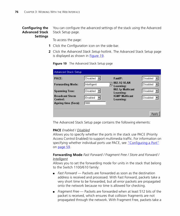
76 CHAPTER 3: WORKING WITH THE WEB INTERFACE
Configuring theAdvanced Stack
Settings
You can configure the advanced settings of the stack using the Advanced Stack Setup page.
To access the page:
1 Click the Configuration icon on the side-bar.
2 Click the Advanced Stack Setup hotlink. The Advanced Stack Setup page is displayed as shown in Figure 19.
Figure 19 The Advanced Stack Setup page
The Advanced Stack Setup page contains the following elements:
PACE Enabled / DisabledAllows you to specify whether the ports in the stack use PACE (Priority Access Control Enabled) to support multimedia traffic. For information on specifying whether individual ports use PACE, see “Configuring a Port” on page 59.
Forwarding Mode Fast Forward / Fragment Free / Store and Forward / IntelligentAllows you to set the forwarding mode for units in the stack that belong to the Switch 1100/610 family:
� Fast Forward — Packets are forwarded as soon as the destination address is received and processed. With Fast Forward, packets take a very short time to be forwarded, but all error packets are propagated onto the network because no time is allowed for checking.
� Fragment Free — Packets are forwarded when at least 512 bits of the packet is received, which ensures that collision fragments are not propagated through the network. With Fragment Free, packets take a
Configuring the Stack 77
short time to be forwarded, but all error packets except fragments are propagated.
� Store and Forward — Received packets are buffered entirely before they are forwarded, which ensures that only good packets are forwarded to their destination. With Store and Forward, packets take slightly longer to be forwarded than with Fast Forward and Fragment Free, but no errors are propagated.
� Intelligent — The stack monitors the amount of error traffic on the network and changes the forwarding mode accordingly. Normally, the stack is in Fast Forward mode. If the stack detects an error rate of greater than 20 errored frames per second, the forwarding mode is set to Store and Forward. It will return to Fast Forward mode once the error rate drops to 1 errored frame per second.
Units in the Switch 3300/630 family only support the Store and Forward forwarding mode. If the stack is set to another forwarding mode, these units use the Store and Forward forwarding mode.
Spanning Tree Enabled / DisabledAllows you to specify whether the stack uses the Spanning Tree Protocol (STP). Using STP makes your network more resilient to link failure and also provides a protection from loops — one of the major causes of broadcast storms; for more information, see “Spanning Tree Protocol” on page 193.
CAUTION: If you enable STP, the stack takes several seconds to configure itself. During this time, you cannot communicate with the stack.
You cannot enable STP if you have set up resilient links on any Switch units in your stack. For more information about resilient links, see “Setting Up Resilient Links” on page 79.
Broadcast Storm Control Enabled / DisabledAllows you to specify whether the stack uses Broadcast Storm Control. If Broadcast Storm Control is enabled, the stack automatically creates an alarm for each port to monitor the level of broadcast traffic on that port. If the broadcast traffic level rises to 2976 frames per second, the broadcast traffic on the port is blocked until the broadcast traffic level drops to 1488 frames per second.
78 CHAPTER 3: WORKING WITH THE WEB INTERFACE
Ageing Time (Secs) 0 / 60 ... 1000000Allows you to specify the ageing time (in seconds) for all learned entries in the Switch Database of the stack; the default time is 1800 seconds (30 minutes). If you specify an ageing time of 0, the ageing process is disabled and the learned entries become non-ageing learned entries. For more information about the Switch Database, see “What is the Switch Database?” on page 72.
FastIP Enabled / DisabledAllows you to specify whether the stack uses FastIP to reduce the load on routing devices when there is a large amount of inter-VLAN traffic on your network. FastIP requires your stacks to support IEEE 802.1Q learning; consequently, if you set the FastIP listbox to enabled, the 802.1Q VLAN Learning listbox is also set to enabled. For more information about FastIP, see “FastIP” on page 181.
CAUTION: If you change the setting of the FastIP listbox, the stack needs to be reset before the change comes into effect.
802.1Q VLAN Learning Enabled / DisabledAllows you to specify whether the ports in the stack use IEEE 802.1Q learning (GVRP) to place ports in VLANs automatically. For more information about IEEE 802.1Q VLAN learning, see “Using IEEE 802.1Q Learning” on page 167.
802.1p Multicast Learning Enabled / DisabledAllows you to specify whether the ports in the stack use IEEE 802.1p multicast filtering (GMRP) to filter and forward multicasts automatically. For more information about IEEE 802.1p multicast filtering, see “IEEE 802.1p Multicast Filtering” on page 191.
IGMP Multicast Learning Enabled / DisabledAllows you to specify whether the ports in the stack use IGMP multicast filtering to filter and forward multicasts automatically. For more information about IGMP multicast filtering, see “IGMP Multicast Filtering” on page 192.
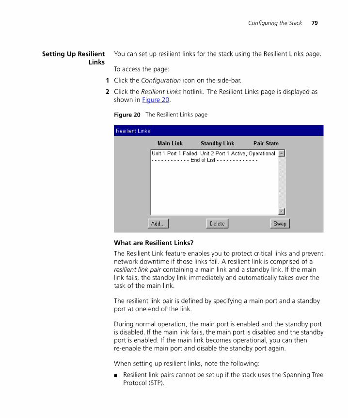
Configuring the Stack 79
Setting Up ResilientLinks
You can set up resilient links for the stack using the Resilient Links page.
To access the page:
1 Click the Configuration icon on the side-bar.
2 Click the Resilient Links hotlink. The Resilient Links page is displayed as shown in Figure 20.
Figure 20 The Resilient Links page
What are Resilient Links?
The Resilient Link feature enables you to protect critical links and prevent network downtime if those links fail. A resilient link is comprised of a resilient link pair containing a main link and a standby link. If the main link fails, the standby link immediately and automatically takes over the task of the main link.
The resilient link pair is defined by specifying a main port and a standby port at one end of the link.
During normal operation, the main port is enabled and the standby port is disabled. If the main link fails, the main port is disabled and the standby port is enabled. If the main link becomes operational, you can then re-enable the main port and disable the standby port again.
When setting up resilient links, note the following:
� Resilient link pairs cannot be set up if the stack uses the Spanning Tree Protocol (STP).
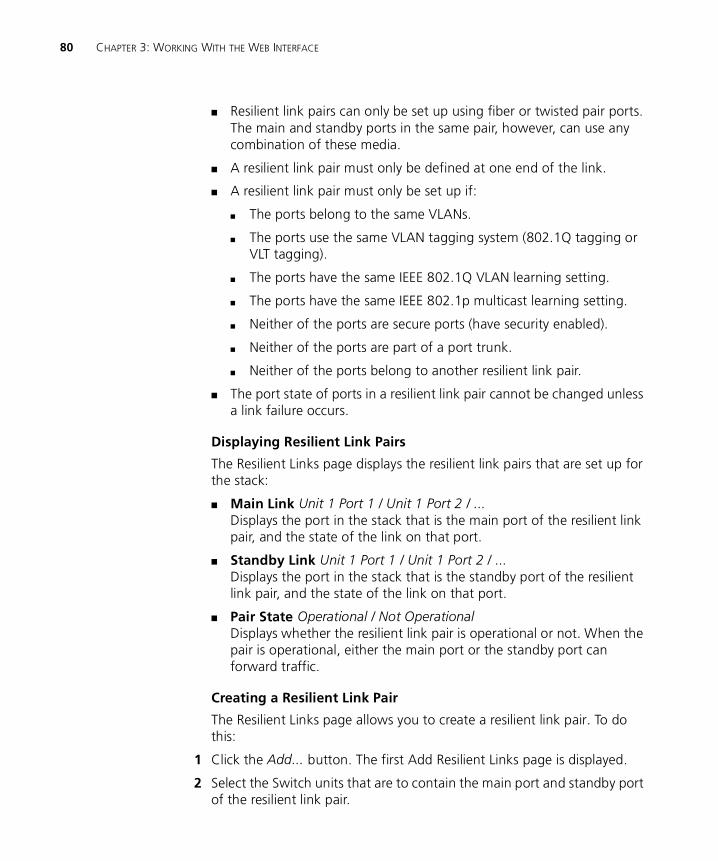
80 CHAPTER 3: WORKING WITH THE WEB INTERFACE
� Resilient link pairs can only be set up using fiber or twisted pair ports. The main and standby ports in the same pair, however, can use any combination of these media.
� A resilient link pair must only be defined at one end of the link.
� A resilient link pair must only be set up if:
� The ports belong to the same VLANs.
� The ports use the same VLAN tagging system (802.1Q tagging or VLT tagging).
� The ports have the same IEEE 802.1Q VLAN learning setting.
� The ports have the same IEEE 802.1p multicast learning setting.
� Neither of the ports are secure ports (have security enabled).
� Neither of the ports are part of a port trunk.
� Neither of the ports belong to another resilient link pair.
� The port state of ports in a resilient link pair cannot be changed unless a link failure occurs.
Displaying Resilient Link Pairs
The Resilient Links page displays the resilient link pairs that are set up for the stack:
� Main Link Unit 1 Port 1 / Unit 1 Port 2 / ...Displays the port in the stack that is the main port of the resilient link pair, and the state of the link on that port.
� Standby Link Unit 1 Port 1 / Unit 1 Port 2 / ...Displays the port in the stack that is the standby port of the resilient link pair, and the state of the link on that port.
� Pair State Operational / Not OperationalDisplays whether the resilient link pair is operational or not. When the pair is operational, either the main port or the standby port can forward traffic.
Creating a Resilient Link Pair
The Resilient Links page allows you to create a resilient link pair. To do this:
1 Click the Add... button. The first Add Resilient Links page is displayed.
2 Select the Switch units that are to contain the main port and standby port of the resilient link pair.

Configuring the Stack 81
3 Click the Next... button.
4 From the Main Link field, select the main port of the resilient link pair.
5 Click the Next... button.
6 From the Standby Link field, select the standby port of the resilient link pair.
7 Click the Next... button. The Resilient Links page is displayed showing the new resilient link pair.
Version 2.6x of the Switch Management Software which will be released towards the end of 2000 has an additional option for resilient links.
After selecting the port for the Standby Link, click the the Next... button. The Switch Mode screen is displayed. From the dropdown list select either:
� Symmetric, if currently in standby, if you wish the link to continue to operate on the standby link even after the main link is re-enabled.
� Switchback, if currently in standby, if you want the link to automatically revert to the main link once the switch detects the main link is operational.
Deleting a Resilient Link Pair
The Resilient Links page allows you to delete a resilient link pair. To do this:
1 Click the resilient link pair.
2 Click the Delete button.
Swapping the Active Port of a Resilient Link Pair
The Resilient Links page allows you to swap the active (or enabled) port of a resilient link pair. To do this:
1 Click the resilient link pair.
2 Click the Swap button.
Setting Up PortTrunks
You can set up port trunks for the stack using the Port Trunk Setup page.
To access the page:
1 Click the Configuration icon on the side-bar.
2 Click the Port Trunks hotlink. The Port Trunks Setup page is displayed as shown in Figure 21.
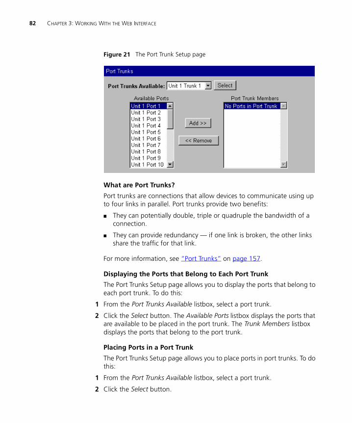
82 CHAPTER 3: WORKING WITH THE WEB INTERFACE
Figure 21 The Port Trunk Setup page
What are Port Trunks?
Port trunks are connections that allow devices to communicate using up to four links in parallel. Port trunks provide two benefits:
� They can potentially double, triple or quadruple the bandwidth of a connection.
� They can provide redundancy — if one link is broken, the other links share the traffic for that link.
For more information, see “Port Trunks” on page 157.
Displaying the Ports that Belong to Each Port Trunk
The Port Trunks Setup page allows you to display the ports that belong to each port trunk. To do this:
1 From the Port Trunks Available listbox, select a port trunk.
2 Click the Select button. The Available Ports listbox displays the ports that are available to be placed in the port trunk. The Trunk Members listbox displays the ports that belong to the port trunk.
Placing Ports in a Port Trunk
The Port Trunks Setup page allows you to place ports in port trunks. To do this:
1 From the Port Trunks Available listbox, select a port trunk.
2 Click the Select button.
Configuring the Stack 83
3 Click a port in the Available Ports listbox.
4 Click the Add >> button. The port is assigned to the port trunk, and the port is displayed in the Trunk Members listbox.
There are several conditions that need to be satisfied before a port can be placed in a port trunk. See “Port Trunks and Your Switch” on page 158.
To place a port back in the Available Ports listbox, click the port in the Trunk Members listbox and click the << Remove button. The first (primary) port cannot be placed back in the Available Ports listbox until the other ports are placed back.
Configuring VLANs You can configure VLANs for the stack using the VLAN Setup page.
To access the page:
1 Click the Configuration icon on the side-bar.
2 Click the VLANs hotlink. The VLAN Setup page is displayed as shown in Figure 22.
Figure 22 The VLAN Setup page
84 CHAPTER 3: WORKING WITH THE WEB INTERFACE
What are VLANs?
A VLAN is a flexible group of devices that can be located anywhere in a network, but they communicate as if they are on the same physical segment. With VLANs, you can segment your network without being restricted by physical connections — a drawback of traditional network design. For more information about VLANs, see “Virtual LANs (VLANs)” on page 163.
Defining VLAN Information
The VLAN Setup page allows you to define the required information about VLANs. To do this:
1 Click the Create... button. The Create VLAN page is displayed.
2 In the VLAN Name field, enter a descriptive name for the VLAN (for example, Marketing or Management). The name can be up to 32 characters long.
3 In the 802.1Q VLAN ID field, enter a unique 802.1Q ID for the VLAN. The 802.1Q ID is used to identify the VLAN if you use 802.1Q tagging across your network, and can be any number between 2 and 4094. You only need to enter an ID in the 802.1Q VLAN ID field if you intend to use 802.1Q tagging on your network.
4 In the Local ID listbox, enter a local ID for the VLAN. The local ID is used to identify the VLAN within the stack, and can be any number between 2 and 16 (VLAN 1, the Default VLAN, is already created and cannot be deleted). The Local ID corresponds to the VLAN IDs used in legacy 3Com devices.
5 Click Apply. The VLAN information is defined, and the VLAN Setup page is displayed showing the port membership for the new VLAN.
Editing VLAN Information
The VLAN Setup page allows you to edit any VLAN information. To do this:
1 From the VLANs Available listbox, select a VLAN.
2 Click the Select button.
3 Click the Edit... button. The Edit VLAN page is displayed.
4 Edit the required information.
5 Click Apply. The VLAN information is edited, and the VLAN Setup page is displayed.
You cannot edit the 802.1Q VLAN ID if ports are assigned to the VLAN.
Configuring the Stack 85
Deleting VLAN Information
The VLAN Setup page allows you to delete any VLAN information that you define in the Create VLAN page. To do this:
1 From the VLANs Available listbox, select a VLAN.
2 Click the Select button.
3 Click the Delete button. The VLAN is deleted, and the VLAN Setup page displays the port membership of the Default VLAN.
You cannot delete the information for a VLAN if ports are assigned to that VLAN.
Displaying the Ports that Belong to Each VLAN
The VLAN Setup page allows you to display the ports that belong to each VLAN. To do this:
1 From the VLANs Available listbox, select a VLAN.
2 Click the Select button. The Available Ports listbox displays the ports in the stack that are available to be placed in the VLAN. The VLAN Members listbox displays the ports in the stack that belong to the VLAN.
Placing Ports in Single VLANs
To place a port in a single VLAN, use the Untagged VLAN listbox on the Port Setup page; see “Configuring a Port” on page 59.
Placing Ports in Multiple VLANs Using VLT Tagging
To place a port in multiple VLANs using VLT tagging, use the VLT Tagging listbox on the Port Setup page; see “Configuring a Port” on page 59.
Placing Ports in Multiple VLANs Using 802.1Q Tagging
The VLAN Setup page allows you to place a port in multiple VLANs using 802.1Q tagging. To do this:
1 From the VLANs Available listbox, select a VLAN.
2 Click the Select button.
3 Click the relevant port in the Available Ports listbox.
4 Click the Add >> button. The port is assigned to the VLAN, and the port is displayed in the VLAN Members listbox.
5 To place the port in another VLAN, repeat steps 1 to 4 with that VLAN.
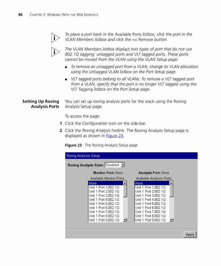
86 CHAPTER 3: WORKING WITH THE WEB INTERFACE
To place a port back in the Available Ports listbox, click the port in the VLAN Members listbox and click the << Remove button.
The VLAN Members listbox displays two types of port that do not use 802.1Q tagging: untagged ports and VLT tagged ports. These ports cannot be moved from the VLAN using the VLAN Setup page:
� To remove an untagged port from a VLAN, change its VLAN allocation using the Untagged VLAN listbox on the Port Setup page.
� VLT tagged ports belong to all VLANs. To remove a VLT tagged port from a VLAN, specify that the port is no longer VLT tagged using the VLT Tagging listbox on the Port Setup page.
Setting Up RovingAnalysis Ports
You can set up roving analysis ports for the stack using the Roving Analysis Setup page.
To access the page:
1 Click the Configuration icon on the side-bar.
2 Click the Roving Analysis hotlink. The Roving Analysis Setup page is displayed as shown in Figure 23.
Figure 23 The Roving Analysis Setup page
Configuring the Stack 87
What is Roving Analysis?
Roving analysis is a system that allows you to attach a network analyzer to one port and use it to monitor the traffic of other ports in the stack. The system works by enabling you to define an analysis port (the port that is connected to the analyzer), and a monitor port (the port that is to be monitored). Once the pair are defined, and you enable the system, the stack takes all the traffic going in and out of the monitor port and copies it to the analysis port.
Roving analysis is used when you need the functions of a network analyzer, but do not want to change the physical characteristics of the monitored segment by attaching an analyzer to that segment.
Defining Monitor Ports and Analysis Ports
The Roving Analysis Setup page allows you to define monitor ports and analysis ports.
To define a monitor port and analysis port:
1 Click a port in the Available Monitor Ports listbox to specify the monitor port.
2 Click a port in the Available Analysis Ports listbox to specify the analysis port.
3 Click Apply.
CAUTION: The analysis port should have a higher bandwidth than the monitor port. Otherwise, the roving analysis system cannot copy all the traffic effectively.
If a port belongs to a port trunk, you cannot specify that it is a monitor port or an analysis port. Consequently, it is not displayed in the Available Monitor Ports listbox or the Available Analysis Ports listbox.
An analysis port must be in the same VLANs as the monitor port it is copying. We therefore recommend that you manually place your analysis ports in all the VLANs used by the stack.
88 CHAPTER 3: WORKING WITH THE WEB INTERFACE
Enabling the Roving Analysis System
The Roving Analysis Setup page allows you to enable the roving analysis system. To do this:
1 From the Roving Analysis State listbox, select Enabled.
2 Click Apply.
Resetting All theUnits in the Stack
You can reset all the Switch units in the stack using the Reset page.
To access the page:
1 Click the Configuration icon on the side-bar.
2 Click the Reset hotlink. The Reset page is displayed.
To reset the stack, select Yes and then click Apply.
What Happens During a Reset?
Resetting the Switch units in the stack simulates a power-off/on cycle. You may want to do this if you need to:
� Remove all the Learned entries in the Switch Database (SDB).
� Reset the statistic counters of the stack.
CAUTION: Resetting the stack causes some of the traffic being transmitted over the network to be lost. It also clears all Learned entries from the Switch Database.
The stack takes about 10 seconds to reset. While the stack is resetting, you cannot communicate with it.
Initializing All theUnits in the Stack
You can initialize all the Switch units in the stack using the Initialize page.
To access the page:
1 Click the Configuration icon on the side-bar.
2 Click the Initialize hotlink. The Initialize page is displayed.
To initialize the stack, select Yes and then click Apply.
What Happens During an Initialization?
Initializing the Switch units in the stack returns them to their default (factory) settings. The only information that does not return to its default
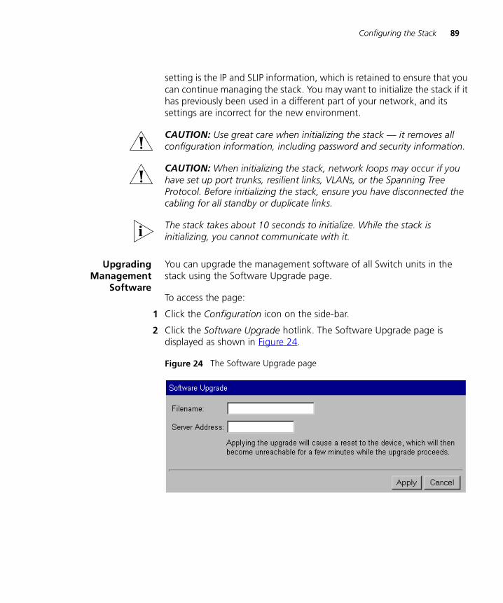
Configuring the Stack 89
setting is the IP and SLIP information, which is retained to ensure that you can continue managing the stack. You may want to initialize the stack if it has previously been used in a different part of your network, and its settings are incorrect for the new environment.
CAUTION: Use great care when initializing the stack — it removes all configuration information, including password and security information.
CAUTION: When initializing the stack, network loops may occur if you have set up port trunks, resilient links, VLANs, or the Spanning Tree Protocol. Before initializing the stack, ensure you have disconnected the cabling for all standby or duplicate links.
The stack takes about 10 seconds to initialize. While the stack is initializing, you cannot communicate with it.
UpgradingManagement
Software
You can upgrade the management software of all Switch units in the stack using the Software Upgrade page.
To access the page:
1 Click the Configuration icon on the side-bar.
2 Click the Software Upgrade hotlink. The Software Upgrade page is displayed as shown in Figure 24.
Figure 24 The Software Upgrade page
90 CHAPTER 3: WORKING WITH THE WEB INTERFACE
To upgrade the management software:
1 Copy the software upgrade file into an appropriate directory on a TFTP server. For information on using a TFTP Server, see the documentation that accompanies it.
CAUTION: You must ensure that the port connected to the TFTP server has 802.1Q VLAN learning disabled and belongs to the Default VLAN (VLAN 1). The server can only upgrade a stack if it is connected to the stack by the Default VLAN.
You can download a TFTP server called 3CServer (filename: 3cs117.zip) from the 3Com website http://www.3com.com. 3CServer can be installed and run on a Microsoft Windows® 95/98 or NT system.
2 Enter the name of the software upgrade file in the Filename field. The filename format is:
s2sxx_yy.bin
where xx_yy is the version of management software.
CAUTION: You must use the s2sxx_yy.bin format, otherwise the upgrade fails.
3 Enter the IP address of the TFTP server in the Server Address field.
4 Click the Apply button. During the upgrade, the Power/Self Test LED flashes green and the command line interface is locked. The units in the stack upgrade one at a time, and each unit takes about 5 minutes; when the upgrade is complete, the Switch units in the stack are reset.
CAUTION: During the upgrade, do not power-down or reset any Switch units in the stack.
A power interrupt during the software upgrade may cause a corrupted agent image on the switch. If this occurs then subsequent rebooting of the switch will be unsuccessful. The front panel LEDs 2 and 3 will be lit and the Power LED will flash. If this happens, the software agent must be upgraded using a serial upgrade. For more information, see Appendix A.
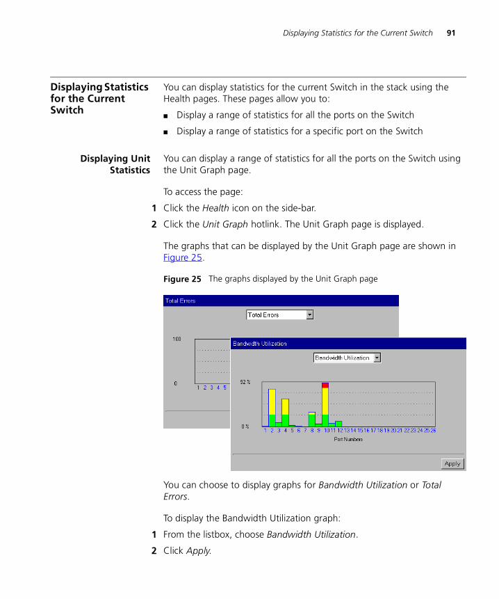
Displaying Statistics for the Current Switch 91
Displaying Statistics for the Current Switch
You can display statistics for the current Switch in the stack using the Health pages. These pages allow you to:
� Display a range of statistics for all the ports on the Switch
� Display a range of statistics for a specific port on the Switch
Displaying UnitStatistics
You can display a range of statistics for all the ports on the Switch using the Unit Graph page.
To access the page:
1 Click the Health icon on the side-bar.
2 Click the Unit Graph hotlink. The Unit Graph page is displayed.
The graphs that can be displayed by the Unit Graph page are shown in Figure 25.
Figure 25 The graphs displayed by the Unit Graph page
You can choose to display graphs for Bandwidth Utilization or Total Errors.
To display the Bandwidth Utilization graph:
1 From the listbox, choose Bandwidth Utilization.
2 Click Apply.
92 CHAPTER 3: WORKING WITH THE WEB INTERFACE
To display the Total Errors graph:
1 From the listbox, choose Total Errors.
2 Click Apply.
If you click a port on the Bandwidth Utilization or Total Errors graph, the graph for that port is displayed.
Interpreting the Statistics
� The Bandwidth Utilization graph scales automatically to display the percentage of bandwidth used on all ports of the Switch over the last 30 seconds:
� A bandwidth utilization of 0–25% (green bar on the graph) indicates that the ports are dealing with a light traffic load.
� A bandwidth utilization of 26–85% (yellow bar on the graph) indicates that the ports are dealing with a normal traffic load.
� A bandwidth utilization of 86–100% (red bar on the graph) indicates that the ports are dealing with a heavy traffic load. This could be caused by a fault in your network, or an inadequate network configuration.
� The Total Errors graph scales automatically to display the total number of packets with errors that have been seen on the ports of the Switch over the last 30 seconds.
Displaying PortStatistics
You can display a range of statistics for a specific port on the Switch using the Port Graph page.
To access the page:
1 Click the Health icon on the side-bar.
2 Click the Port Graph hotlink. The Port Graph page is displayed.
The graphs that can be displayed by the Port Graph page are shown in Figure 26.
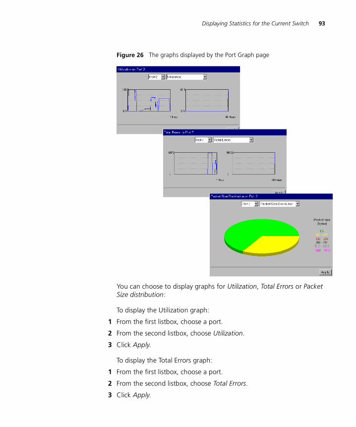
Displaying Statistics for the Current Switch 93
Figure 26 The graphs displayed by the Port Graph page
You can choose to display graphs for Utilization, Total Errors or Packet Size distribution:
To display the Utilization graph:
1 From the first listbox, choose a port.
2 From the second listbox, choose Utilization.
3 Click Apply.
To display the Total Errors graph:
1 From the first listbox, choose a port.
2 From the second listbox, choose Total Errors.
3 Click Apply.

94 CHAPTER 3: WORKING WITH THE WEB INTERFACE
To display the Packet Size Distribution graph:
1 From the first listbox, choose a port.
2 From the second listbox, choose Packet Size Distribution.
3 Click Apply.
Interpreting the Statistics
� The Utilization graph scales automatically to display the percentage of bandwidth used on the port over the last hour and last 48 hours:
� A bandwidth utilization of 0–25% indicates that the port is dealing with a light traffic load.
� A bandwidth utilization of 26–85% indicates that the port is dealing with a normal traffic load.
� A bandwidth utilization of 86–100% indicates that the port is dealing with a heavy traffic load. This could be caused by a fault in your network, or an inadequate network configuration.
� The Total Errors graph scales automatically to display the total number of packets with errors that have been seen on the port over the last hour and last 48 hours.
� The Packet Size Distribution graph displays the proportion of packets of certain sizes seen by the port over the last 30 seconds.
4
WORKING WITH THE COMMAND LINE INTERFACEThis chapter describes how to access and use the command line interface. It covers the following topics:
� Accessing the Interface
� About the Interface Menus
� A Quick Guide to the Commands
� Displaying and Changing Bridging/VLANs Information
� Displaying and Changing Port Information
� Displaying and Changing System Feature Information
� Displaying and Changing IP-related Information
� Displaying and Changing SNMP-related Information
� Displaying and Changing Stack Information
Throughout this chapter, the term stack refers to a number of Switch units that are managed as a single unit. However, a stack can contain a single Switch.
96 CHAPTER 4: WORKING WITH THE COMMAND LINE INTERFACE
Accessing the Interface
To access the command line interface, take the following steps:
1 Set up your network for command line interface management; for more information, see “Setting Up Command Line Interface Management” on page 36. The login sequence for the command line interface begins as soon as a relevant Switch in the stack detects a connection to its console port, or as soon as a Telnet session is started.
If the login sequence does not begin immediately, press the [Return] key a few times until it does begin. If the sequence still does not begin, see “Solving Command Line Interface Problems” on page 216.
2 At the login and password prompts, enter your user name and password.
� If you have been assigned a user name and password, enter those details.
� If you are accessing the command line interface for the first time, enter a default user name and password to match your access requirements. The defaults are described in “Logging in as a Default User” on page 39. If you are setting up the stack for management, we suggest that you log in as admin (which has no default password).
If you have logged on correctly, the top-level menu of the command line interface is displayed as described in “About the Interface Menus” on page 97. If you have not logged on correctly, the message Incorrect password. is displayed and the login sequence starts again.
To prevent unauthorized configuration of the stack, we recommend that you change the default passwords as soon as possible. To do this using the command line interface, you need to log in as each default user and then follow the steps described in “Changing Your Password” on page 147.
You may experience a slow CLI response if differing community strings are configured for units in a stack. You should ensure that all units in a stack are configured with matching community strings.
Exiting the Interface You can exit the command line interface at any time; to do this, enter the command logout from the top level of the command line interface. If there is a period if inactivity lasting longer than 30 minutes, you exit from the command line interface automatically. After the exit, the first key that you press returns you to the login sequence.
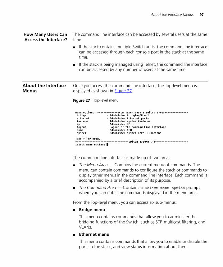
About the Interface Menus 97
How Many Users CanAccess the Interface?
The command line interface can be accessed by several users at the same time:
� If the stack contains multiple Switch units, the command line interface can be accessed through each console port in the stack at the same time.
� If the stack is being managed using Telnet, the command line interface can be accessed by any number of users at the same time.
About the Interface Menus
Once you access the command line interface, the Top-level menu is displayed as shown in Figure 27.
Figure 27 Top-level menu
The command line interface is made up of two areas:
� The Menu Area — Contains the current menu of commands. The menu can contain commands to configure the stack or commands to display other menus in the command line interface. Each command is accompanied by a brief description of its purpose.
� The Command Area — Contains a Select menu option prompt where you can enter the commands displayed in the menu area.
From the Top-level menu, you can access six sub-menus:
� Bridge menu
This menu contains commands that allow you to administer the bridging functions of the Switch, such as STP, multicast filtering, and VLANs.
� Ethernet menu
This menu contains commands that allow you to enable or disable the ports in the stack, and view status information about them.
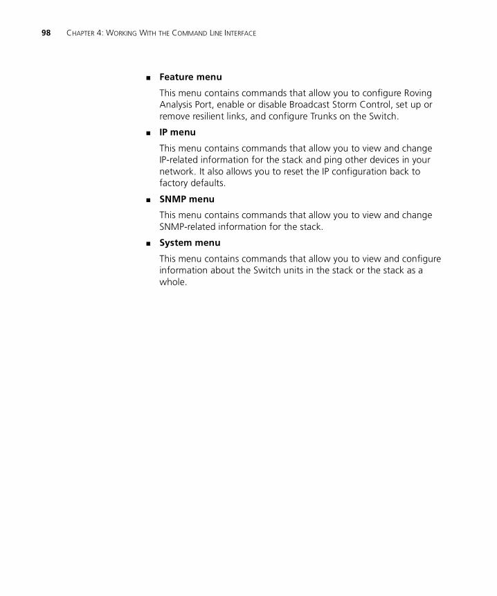
98 CHAPTER 4: WORKING WITH THE COMMAND LINE INTERFACE
� Feature menu
This menu contains commands that allow you to configure Roving Analysis Port, enable or disable Broadcast Storm Control, set up or remove resilient links, and configure Trunks on the Switch.
� IP menu
This menu contains commands that allow you to view and change IP-related information for the stack and ping other devices in your network. It also allows you to reset the IP configuration back to factory defaults.
� SNMP menu
This menu contains commands that allow you to view and change SNMP-related information for the stack.
� System menu
This menu contains commands that allow you to view and configure information about the Switch units in the stack or the stack as a whole.
About the Interface Menus 99
Figure 28 Command line interface menu structure
Entering Commands The command area of the command line interface contains a Select menu option prompt that allows you to enter the commands in the menu area
Commands are not case-sensitive.
� To enter a simple command:
At the prompt, enter the name of the command.
100 CHAPTER 4: WORKING WITH THE COMMAND LINE INTERFACE
� To enter multiple commands:
At the prompt, enter each command in succession. For example, to display the system menu and reset the Switch units in the stack, enter:
system reset
� To enter commands that require values:
Append the values to the name of the command. For example, to display the system menu and change your password, enter:
system password <password>
If you do not specify values for a command that requires them, you are prompted to enter the values. At each prompt, the default value is displayed in brackets.
� To enter abbreviated commands
At the prompt, enter enough characters to uniquely identify the commands. For example, to display the system menu and then change the password for your user, enter:
sy pa <password>
Displaying Menus There are several ways to display the menus in the command line interface menu structure:
� To display sub-menus:
At the Select menu option prompt, enter the name of the menu or menus.
� To display parent menus:
At the Select menu option prompt, enter q.
� To display the Top-level menu:
Press the [Esc] key.
Obtaining Help You can access the command line interface help system at any time by entering ? at the Select menu option prompt.
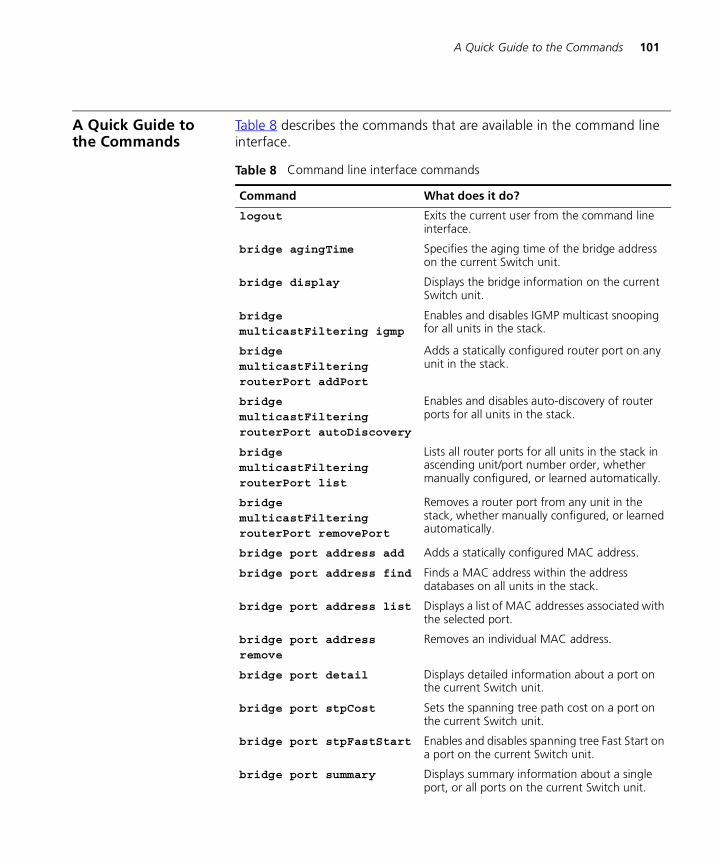
A Quick Guide to the Commands 101
A Quick Guide to the Commands
Table 8 describes the commands that are available in the command line interface.
Table 8 Command line interface commands
Command What does it do?
logout Exits the current user from the command line interface.
bridge agingTime Specifies the aging time of the bridge address on the current Switch unit.
bridge display Displays the bridge information on the current Switch unit.
bridge multicastFiltering igmp
Enables and disables IGMP multicast snooping for all units in the stack.
bridge multicastFiltering routerPort addPort
Adds a statically configured router port on any unit in the stack.
bridge multicastFiltering routerPort autoDiscovery
Enables and disables auto-discovery of router ports for all units in the stack.
bridge multicastFiltering routerPort list
Lists all router ports for all units in the stack in ascending unit/port number order, whether manually configured, or learned automatically.
bridge multicastFiltering routerPort removePort
Removes a router port from any unit in the stack, whether manually configured, or learned automatically.
bridge port address add Adds a statically configured MAC address.
bridge port address find Finds a MAC address within the address databases on all units in the stack.
bridge port address list Displays a list of MAC addresses associated with the selected port.
bridge port address remove
Removes an individual MAC address.
bridge port detail Displays detailed information about a port on the current Switch unit.
bridge port stpCost Sets the spanning tree path cost on a port on the current Switch unit.
bridge port stpFastStart Enables and disables spanning tree Fast Start on a port on the current Switch unit.
bridge port summary Displays summary information about a single port, or all ports on the current Switch unit.
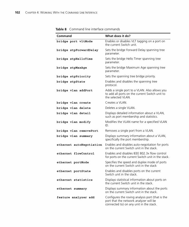
102 CHAPTER 4: WORKING WITH THE COMMAND LINE INTERFACE
bridge port vltMode Enables or disables VLT tagging on a port on the current Switch unit.
bridge stpForwardDelay Sets the bridge Forward Delay spanning tree parameter.
bridge stpHelloTime Sets the bridge Hello Timer spanning tree parameter.
bridge stpMaxAge Sets the bridge Maximum Age spanning tree parameter.
bridge stpPriority Sets the spanning tree bridge priority.
bridge stpState Enables and disables the spanning tree protocol.
bridge vlan addPort Adds a single port to a VLAN. Also allows you to add all ports on the current Switch unit to the selected VLAN.
bridge vlan create Creates a VLAN.
bridge vlan delete Deletes a single VLAN.
bridge vlan detail Displays detailed information about a VLAN, such as port membership and statistics.
bridge vlan modify Modifies the VLAN name for a specified VLAN ID.
bridge vlan removePort Removes a single port from a VLAN.
bridge vlan summary Displays summary information about a VLAN, specifically the port membership.
ethernet autoNegotiation Enables and disables auto-negotiation for ports on the current Switch unit in the stack.
ethernet flowControl Enables and disables IEEE 802.3x flow control for ports on the current Switch unit in the stack.
ethernet portMode Specifies the speed and duplex mode of ports on the current Switch unit in the stack
ethernet portState Enables and disables ports on the current Switch unit in the stack.
ethernet statistics Displays statistical information about ports on the current Switch unit in the stack.
ethernet summary Displays summary information about the ports on the current Switch unit in the stack.
feature analyzer add Configures the roving analysis port (that is the port that the network analyzer will be connected to) on any unit in the stack.
Table 8 Command line interface commands
Command What does it do?

A Quick Guide to the Commands 103
feature analyzer display Displays information about the roving analysis port configured in the stack.
feature analyzer remove Removes the designated roving analysis port from the current port.
feature analyzer start Specifies the roving analysis monitor port (that is the port from which data will be copied) and starts monitoring by the analysis port.
feature analyzer stop Disables roving analysis and removes the monitor port from the roving analysis configuration.
feature broadcastStormControl
Enables and disables Broadcast Storm Control.
feature resilience define
Creates a resilient link.
feature resilience detail
Displays summary information about all resilient links present in the stack.
feature resilience remove
Deletes a resilient link.
feature resilience swap Swaps over the “active” resilient link.
feature trunk addPort Adds a single port to a trunk.
feature trunk detail Displays detailed information about the trunks supported by the current Switch unit.
feature trunk removePort Removes a single port from a trunk on the current Switch unit.
feature trunk summary Displays summary information about all trunks.
ip interface bootp Enables and disables BOOTP for the current Switch unit in the stack.
ip interface define Specifies the IP information for the current Switch unit in the stack.
ip interface display Displays the IP information for the current Switch unit in the stack.
ip ping Allows you to ping other devices on your network.
ip initializeConfig Allows you to reset the IP configuration back to factory defaults. This command operates on the whole stack.
snmp community Specifies SNMP community strings for the stack.
Table 8 Command line interface commands
Command What does it do?
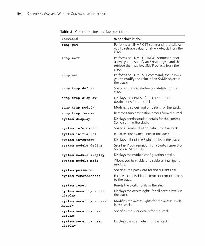
104 CHAPTER 4: WORKING WITH THE COMMAND LINE INTERFACE
snmp get Performs an SNMP GET command, that allows you to retrieve values of SNMP objects from the stack.
snmp next Performs an SNMP GETNEXT command, that allows you to specify an SNMP object and then retrieve the next few SNMP objects from the stack.
snmp set Performs an SNMP SET command, that allows you to modify the value of an SNMP object in the stack.
snmp trap define Specifies the trap destination details for the stack.
snmp trap display Displays the details of the current trap destinations for the stack.
snmp trap modify Modifies trap destination details for the stack.
snmp trap remove Removes trap destination details from the stack.
system display Displays administration details for the current Switch unit in the stack.
system information Specifies administration details for the stack.
system initialize Initializes the Switch units in the stack.
system inventory Displays a list of the Switch units in the stack.
system module define Sets the IP configuration for a Switch Layer 3 or Switch ATM module.
system module display Displays the module configuration details.
system module mode Allows you to enable or disable an intelligent module.
system password Specifies the password for the current user.
system remoteAccess Enables and disables all forms of remote access to the stack.
system reset Resets the Switch units in the stack.
system security access display
Displays the access rights for all access levels in the stack.
system security access modify
Modifies the access rights for the access levels in the stack.
system security user define
Specifies the user details for the stack.
system security user display
Displays the user details for the stack.
Table 8 Command line interface commands
Command What does it do?
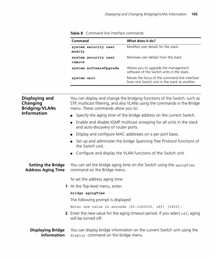
Displaying and Changing Bridging/VLANs Information 105
Displaying and Changing Bridging/VLANs Information
You can display and change the bridging functions of the Switch, such as STP, multicast filtering, and also VLANs using the commands in the Bridge menu. These commands allow you to:
� Specify the aging time of the bridge address on the current Switch.
� Enable and disable IGMP multicast snooping for all units in the stack and auto-discovery of router ports.
� Display and configure MAC addresses on a per port basis.
� Set up and administer the bridge Spanning Tree Protocol functions of the Switch unit.
� Configure and display the VLAN functions of the Switch unit.
Setting the BridgeAddress Aging Time
You can set the bridge aging time on the Switch using the agingTime command on the Bridge menu.
To set the address aging time:
1 At the Top-level menu, enter:
bridge agingTime
The following prompt is displayed:
Enter new value in seconds (60-1000000, off) [1800]:
2 Enter the new value for the aging timeout period. If you select off, aging will be turned off.
Displaying BridgeInformation
You can display bridge information on the current Switch unit using the display command on the bridge menu.
system security user modify
Modifies user details for the stack.
system security user remove
Removes user details from the stack.
system softwareUpgrade Allows you to upgrade the management software of the Switch units in the stack.
system unit Moves the focus of the command line interface from one Switch unit in the stack to another.
Table 8 Command line interface commands
Command What does it do?
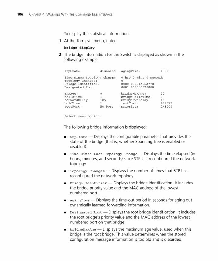
106 CHAPTER 4: WORKING WITH THE COMMAND LINE INTERFACE
To display the statistical information:
1 At the Top-level menu, enter:
bridge display
2 The bridge information for the Switch is displayed as shown in the following example.
The following bridge information is displayed:
� StpState — Displays the configurable parameter that provides the state of the bridge (that is, whether Spanning Tree is enabled or disabled).
� Time Since Last Topology Change — Displays the time elapsed (in hours, minutes, and seconds) since STP last reconfigured the network topology.
� Topology Changes — Displays the number of times that STP has reconfigured the network topology.
� Bridge Identifier — Displays the bridge identification. It includes the bridge priority value and the MAC address of the lowest numbered port.
� agingTime — Displays the time-out period in seconds for aging out dynamically learned forwarding information.
� Designated Root — Displays the root bridge identification. It includes the root bridge's priority value and the MAC address of the lowest numbered port on that bridge.
� bridgeMaxAge — Displays the maximum age value, used when this bridge is the root bridge. This value determines when the stored configuration message information is too old and is discarded.
stpState: disabled agingTime: 1800
Time since topology change: 0 hrs 0 mins 0 secondsTopology Changes: 0Bridge Identifier: 8000 08004e56d778Designated Root: 0001 000000020000
maxAge: 0 bridgeMaxAge: 20helloTime: 1 bridgeHelloTime: 2forwardDelay: 105 bridgeFwdDelay: 15holdTime: 1 rootCost: 131072rootPort: No Port priority: 0x8000
Select menu option:
Displaying and Changing Bridging/VLANs Information 107
� maxAge — Displays the maximum age in seconds at which the stored configuration message information is judged to be too old and is discarded. This value is determined by the root bridge.
� bridgeHelloTime — Displays the Hello time value, used when this bridge is the root bridge. This value is the time that elapses between the configuration messages generated by a bridge that assumes itself to be the root.
� helloTime — Displays the time that elapses between the configuration messages generated by a bridge that assumes itself to be the root.
� bridgeFwdDelay — Displays the forward delay value used when this bridge is the root bridge. This value sets the amount of time that a bridge spends in the listening and learning states.
� forwardDelay — Displays the time that a bridge spends in the "listening" and "learning" states.
� holdTime — Displays the minimum delay time in seconds between sending topology change Bridge Notification Protocol Data Units (BPDUs).
� rootCost — Displays the cost of the best path to the root from the root port of the bridge. For example, one determining factor of cost is the speed of the network interface, that is, the faster the speed, the smaller the cost.
� rootPort — Displays the port with the best path from the bridge to the root bridge. Will display a port number, or No Port.
� priority — Displays the configurable value that is appended as the most significant portion of a bridge identifier.
Enabling andDisabling IGMP
Snooping
You can enable or disable IGMP Snooping for all Switch units in the stack using the IGMP command on the Multicast Filtering menu.
To enable or disable IGMP Snooping:
1 At the Top-level menu, enter:
bridge multicastFiltering igmp
The following prompt is displayed:
Enter new value (disable, enable) [disable]:
2 Enter enable or disable.
108 CHAPTER 4: WORKING WITH THE COMMAND LINE INTERFACE
Enabling andDisabling Router Port
Auto-Discovery
You can enable or disable router port auto-discovery for all Switch units in the stack using the autoDiscovery command on the Router Port menu.
The default setting for the Switch is router port auto-discovery enabled, with no manually identified router ports. You can manually identify router ports with auto-discovery enabled.
To enable or disable router port auto-discovery:
1 At the Top-level menu, enter:
bridge multicastFiltering routerPort autoDiscovery
The following prompt is displayed:
Enter new value (enable, disable) [enable]:
2 Enter enable or disable.
Manually Identifyinga Router Port
You can manually identify router ports for all Switch units in the stack using the addPort command on the Router Port menu.
To manually define a router port:
1 At the Top-level menu, enter:
bridge multicastFiltering routerPort addPort
The following prompt is displayed:
Select unit for router port (1-4) [1]:
2 Enter the number of unit for the router port.
The following prompt is displayed:
Select router port (1-12):
3 Enter the number of the router port.
Displaying all RouterPorts
You can display a list of router ports for all Switch units in the stack using the list command on the Router Port menu.
This list displays all router ports whether manually configured, or automatically learned via auto-discovery.
To display all router ports:
1 At the Top-level menu, enter:
bridge multicastFiltering routerPort list

Displaying and Changing Bridging/VLANs Information 109
2 The router port information for all Switch units in the stack is displayed in ascending unit and port number order.
An example of the router port information is shown below:
Removing a RouterPort
You can remove a router port from any Switch unit in the stack using the removePort command on the Router Port menu. This command can remove router ports whether manually configured, or automatically learned by IGMP Snooping.
To remove a router port:
1 At the Top-level menu, enter:
bridge multicastFiltering routerPort removePort
The following prompt is displayed:
Select unit for router port (1,2,4):
The list in the prompt only includes the units in the stack that have router ports on them.
2 Enter the number of unit for the router port that you wish to remove.
The following prompt is displayed:
Select router port (3,4,all):
The list in the prompt only includes the router ports on the selected unit.
3 Enter the number of the router port that you wish to remove.
Unit Port Learning State1 3 Auto1 4 Manual2 26 Manual4 6 Auto
110 CHAPTER 4: WORKING WITH THE COMMAND LINE INTERFACE
Adding a StaticallyConfigured Address
to a Switch Database
You can add a statically configured address to a switch database using the add command on the Address menu.
To add an address to a port:
1 At the Top-level menu, enter:
bridge port address add
The following prompt is displayed:
Select bridge port(1-12):
2 Enter the number of the port that you wish to add an address to.
The following prompt is displayed:
Enter the address to be added:
3 Enter the address, which must be entered in the form of hyphen separated bytes, for example: 08-00-02-06-03-bd.
The following prompt is displayed:
Enter the VLAN ID for this address (1-4094) [1]:
4 Enter the VLAN ID for the newly assigned address.
Finding a MACAddress
You can find a MAC address within the address databases on all Switch units within the stack using the find command on the Address menu.
To find a port MAC address:
1 At the Top-level menu, enter:
bridge port address find
The following prompt is displayed:
Enter the address:
2 Enter the address that you wish to find. The address must be entered in the form of hyphen separated bytes, for example: 08-00-02-06-03-bd.
The command produces a display that shows all occurrences of the address within the stack forwarding database and indicates the unit and port number associated with it.
Displaying and Changing Bridging/VLANs Information 111
Displaying MACAddresses for a Port
You can display a list of MAC addresses associated with a selected port using the list command on the Address menu.
To display a list of MAC addresses:
1 At the Top-level menu, enter:
bridge port address list
The following prompt is displayed:
Select bridge ports (1-12, all):
2 Enter the number of the port that you wish to have its associated MAC addresses displayed, or enter all for all the ports.
The command produces a list of all MAC addresses associated with the specified port(s).
Removing MACAddresses from a Port
You can remove a MAC address associated with a selected port using the remove command on the Address menu.
To remove a MAC address:
1 At the Top-level menu, enter:
bridge port address remove
The following prompt is displayed:
Enter the address to be removed:
2 Enter the address that you wish to remove. The address must be entered in the form of hyphen separated bytes, for example: 08-00-02-06-03-bd.
The following prompt is displayed:
Enter the VLAN ID for this address (1-4094) [1]:
3 Enter the VLAN ID for the address that you wish to remove.
Displaying PortInformation
You can display information about a port on the current Switch unit using the detail command on the Port menu.
To display the port information:
1 At the Top-level menu, enter:
bridge port detail
The following prompt is displayed:
Select bridge port (1-12):
112 CHAPTER 4: WORKING WITH THE COMMAND LINE INTERFACE
2 Enter the number of a port on the Switch unit. If the port selected is working in VLT mode the display will show the port as being a member of all current VLANs with Tagging shown as vlt.
The port information for the Switch is displayed as shown in the example below.
Setting the SpanningTree Path Cost
You can set the spanning tree path cost on a port of the current Switch using the stpCost command on the Port menu.
To set the spanning tree path cost:
1 At the Top-level menu, enter:
bridge port stpCost
The following prompt is displayed:
Select bridge port (1-12):
2 Enter the number of the port.
The following prompt is displayed:
Enter new value (1-65535) [10]:
3 Enter the new value for the spanning tree path cost on the port.
Enabling andDisabling Spanning
Tree Fast Start
You can enable or disable spanning tree fast start on a port of the current Switch unit using the stpFastStart command on the Port menu.
To enable or disable spanning tree fast start:
1 At the Top-level menu, enter:
bridge port stpFastStart
The following prompt is displayed:
Select bridge ports (1-12) [1]:
Unit 2, Port 1 Detailed Information
State: Disabled fwdTransitions: 0StpCost: 19 BroadcastStormControl: Enabled
VLAN Membership
VLAN ID Local ID Vlan Name Tagging-----------------------------------------------------------1 1 Default VLAN None
Select menu option:
Displaying and Changing Bridging/VLANs Information 113
2 Enter the number of the port to be enabled or disabled.
The following prompt is displayed:
Enter new value (disable, enable) [disable]:
3 Enter enable or disable.
Displaying PortSummary
Information
You can display summary information about a port, or all ports, of the current Switch unit using the summary command on the Port menu.
To display the port summary information:
1 At the Top-level menu, enter:
bridge port summary
The following prompt is displayed:
Select bridge port (1-12, all) [all]:
2 Enter the number of a port on the Switch unit, or all.
The port summary information for the Switch is displayed as shown in the example below.
The following port summary information is displayed:
� State — Displays the parameters that provide the state of the port, the possible values are:
� Disabled - port is disabled
� Link Down - port is enabled but link is down
� Blocking - equivalent to STP blocking state
Port stpState fwdTransitions stpCost-------------------------------------------------------1 Disabled 0 192 Disabled 0 193 Disabled 0 194 Disabled 0 195 Disabled 0 196 Disabled 0 197 Disabled 0 198 Disabled 0 199 Disabled 0 1910 Disabled 0 1911 Disabled 0 1912 Disabled 0 1913 Disabled 0 19
Select menu option:
114 CHAPTER 4: WORKING WITH THE COMMAND LINE INTERFACE
� Listening - equivalent to STP listening state
� Learning - equivalent to STP learning state
� Forwarding - equivalent to STP forwarding state
� Broken - port is broken
� fwdTransitions — Displays the number of times this port has entered the forwarding state from the learning state.
� stpCost — Displays the current path cost associated with the port.
Enabling andDisabling VLT Tagging
on a Port
You can enable or disable VLT tagging on a port of the current Switch unit using the vltMode command on the Port menu.
To enable or disable VLT tagging on a port:
1 At the Top-level menu, enter:
bridge port vltMode
The following prompt is displayed:
Select bridge ports (1-12) [1]:
2 Enter the number of the port to have VLT tagging enabled or disabled.
The following prompt is displayed:
Enter new value (disable, enable) [disable]:
3 Enter enable or disable.
Setting the BridgeSpanning TreeForward Delay
You can set the bridge forward delay spanning tree parameter of the current Switch using the stpForwardDelay command on the Bridge menu.
To set the bridge spanning tree forward delay:
1 At the Top-level menu, enter:
bridge stpForwardDelay
The following prompt is displayed:
Enter new value in seconds (4-30) [15]:
2 Enter the new value for the forward delay.

Displaying and Changing Bridging/VLANs Information 115
Setting the BridgeSpanning Tree Hello
Timer
You can set the bridge hello timer spanning tree parameter of the current Switch using the stpHelloTime command on the Bridge menu.
To set the bridge spanning tree hello timer:
1 At the Top-level menu, enter:
bridge stpHelloTime
The following prompt is displayed:
Enter new value in seconds (1-10) [2]:
2 Enter the new value for the hello timer.
Setting the BridgeSpanning TreeMaximum Age
You can set the bridge maximum age spanning tree parameter of the current Switch using the stpMaxAge command on the Bridge menu.
To set the bridge spanning tree maximum age:
1 At the Top-level menu, enter:
bridge stpMaxAge
The following prompt is displayed:
Enter new value in seconds (6-40) [20]:
2 Enter the new value for the maximum age.
Setting the SpanningTree Bridge Priority
You can set the spanning tree bridge priority of the current Switch using the stpPriority command on the Bridge menu.
To set the spanning tree bridge priority:
1 At the Top-level menu, enter:
bridge stpPriority
The following prompt is displayed:
Enter new hexadecimal value (0x0-0xffff) [0x8000]:
2 Enter the new hexadecimal value for the bridge priority. (The default option indicates the current value of the stpPriority MIB item.)
116 CHAPTER 4: WORKING WITH THE COMMAND LINE INTERFACE
Enabling andDisabling Spanning
Tree on a Bridge
You can enable or disable spanning tree on a bridge of the current Switch unit using the stpState command on the Bridge menu.
To enable or disable spanning tree on a bridge:
1 At the Top-level menu, enter:
bridge stpState
The following prompt is displayed:
Enter new value (disable, enable) [disable]:
2 Enter enable or disable.
Adding a Port to aVLAN
You can add a single port to a VLAN, or add all ports on the current Switch unit to the selected VLAN using the addPort command on the VLAN menu.
To add a port to a VLAN:
1 At the Top-level menu, enter:
bridge vlan addPort
The following prompt is displayed:
Select VLAN ID (1-4094) [1]:
2 Enter the number of the VLAN ID that you wish to add a port to.
The following prompt is displayed:
Enter port (1-12, all):
3 Enter the port number to be added to the VLAN, or enter all for all ports on the current Switch unit to be added.
The following prompt is displayed:
Enter tag type (none, 802.1Q):
4 Enter the tagging information for the port added to the VLAN.
Creating a VLAN You can create a VLAN using the create command on the VLAN menu.
To create a VLAN:
1 At the Top-level menu, enter:
bridge vlan create
Displaying and Changing Bridging/VLANs Information 117
The following prompt is displayed:
Enter VLAN ID (2-4094) [3]:
2 Enter the number of the VLAN ID that you wish to create. The default option is the lowest value within the VLAN ID range not currently used in the stack.
The following prompt is displayed:
Enter Local ID (1-16) [3]:
3 Enter the local ID to be associated with the VLAN. The default option is the lowest value within the Local ID range not currently used in the stack.
The following prompt is displayed:
Enter VLAN Name [VLAN 3]:
4 Enter the name for the VLAN. The VLAN name can be a maximum of 32 characters, including spaces. The default VLAN name is VLAN x, where x is the VLAN ID.
Deleting a VLAN You can delete a VLAN using the delete command on the VLAN menu.
To delete a VLAN:
1 At the Top-level menu, enter:
bridge vlan delete
The following prompt is displayed:
Select VLAN ID (2-4094):
2 Enter the VLAN ID that you wish to delete. If the VLAN contains member ports, a warning message is displayed that asks you to confirm deletion of the VLAN.
Displaying DetailedVLAN Information
You can display detailed information about a VLAN, specifically port membership and statistics, for each Switch unit in the stack that is a member of the specified VLAN using the detail command on the VLAN menu.
To display detailed VLAN information:
1 At the Top-level menu, enter:
bridge vlan detail
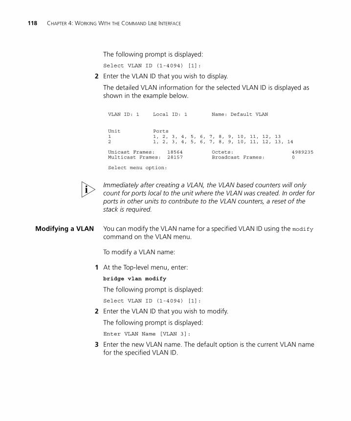
118 CHAPTER 4: WORKING WITH THE COMMAND LINE INTERFACE
The following prompt is displayed:
Select VLAN ID (1-4094) [1]:
2 Enter the VLAN ID that you wish to display.
The detailed VLAN information for the selected VLAN ID is displayed as shown in the example below.
Immediately after creating a VLAN, the VLAN based counters will only count for ports local to the unit where the VLAN was created. In order for ports in other units to contribute to the VLAN counters, a reset of the stack is required.
Modifying a VLAN You can modify the VLAN name for a specified VLAN ID using the modify command on the VLAN menu.
To modify a VLAN name:
1 At the Top-level menu, enter:
bridge vlan modify
The following prompt is displayed:
Select VLAN ID (1-4094) [1]:
2 Enter the VLAN ID that you wish to modify.
The following prompt is displayed:
Enter VLAN Name [VLAN 3]:
3 Enter the new VLAN name. The default option is the current VLAN name for the specified VLAN ID.
VLAN ID: 1 Local ID: 1 Name: Default VLAN
Unit Ports1 1, 2, 3, 4, 5, 6, 7, 8, 9, 10, 11, 12, 132 1, 2, 3, 4, 5, 6, 7, 8, 9, 10, 11, 12, 13, 14
Unicast Frames: 18564 Octets: 4989235Multicast Frames: 28157 Broadcast Frames: 0
Select menu option:
Displaying and Changing Bridging/VLANs Information 119
Removing a Port froma VLAN
You can remove a single port from a VLAN, or remove all ports on the current Switch unit from the selected VLAN using the removePort command on the VLAN menu.
To remove a port from a VLAN:
1 At the Top-level menu, enter:
bridge vlan removePort
The following prompt is displayed:
Select VLAN ID (1-4094) [1]:
2 Enter the number of the VLAN ID that you wish to remove a port from.
The following prompt is displayed:
Select port (1,5,7,all):
3 Enter the port number to be removed from the VLAN, or enter all for all ports on the current Switch unit to be removed. The choice of port numbers reflects the number of ports on the current Switch unit. An error message is displayed if there are no ports within the selected VLAN.
Displaying SummaryVLAN Information
You can display summary information about a single VLAN or all VLANs present in the stack, specifically port membership, using the summary command on the VLAN menu.
To display summary VLAN information:
1 At the Top-level menu, enter:
bridge vlan summary
The following prompt is displayed:
Select VLAN ID (1-4094, all) [1]:
2 Enter the VLAN ID that you wish to display, or enter all to display all VLANs in the current stack.
The summary VLAN information for the selected VLAN ID is displayed as shown in the example below.
VLAN ID Local ID Name1 1 Default VLAN
Select menu option:
120 CHAPTER 4: WORKING WITH THE COMMAND LINE INTERFACE
Displaying and Changing Port Information
You can display and change information about the ports on the current Switch unit in the stack using the commands on the Ethernet menu. These commands allow you to:
� Enable and disable Ethernet ports on the Switch
� Specify the speed and duplex mode of Ethernet ports on the Switch
� Enable and disable auto-negotiation for Ethernet ports on the Switch
� Enable and disable IEEE 802.3x flow control for Ethernet ports on the Switch
� Display statistical information about Ethernet ports on the Switch
� Display summary information about Ethernet ports on the Switch
To display and change information about the ports on another Switch unit in the stack, you need to select that unit using the unit command For more information, see “Moving the Focus of the Command Line Interface” on page 142.
Enabling andDisabling Ports
You can enable and disable Ethernet ports on the Switch using the portState command on the Ethernet menu.
By default, all ports on the Switch are enabled.
To enable or disable a port:
1 At the Top-level menu, enter:
ethernet portState
The following prompt is displayed:
Select Ethernet port(s) (1-24):
2 Enter the number of the port to be enabled or disabled.
The following prompt is displayed:
Enter new value (enable, disable) [enable]:
3 Enter enable or disable.
Displaying and Changing Port Information 121
Specifying the Speedand Duplex Mode
You can specify the speed and duplex mode of Ethernet ports on the Switch using the portMode command on the Ethernet menu.
To specify the speed and duplex mode of a port:
1 At the Top-level menu, enter:
ethernet portMode
The following prompt is displayed:
Select Ethernet port (1-24,all):
2 Enter the number of the port to have its speed and duplex mode specified, or enter all for all the ports.
� If the port is a 10BASE-T/100BASE-TX port, the following prompt is displayed:
Enter new value (10half,10full,100half,100full):
� If the port is a 100BASE-FX port, the following prompt is displayed:
Enter new value (100half,100full):
� If the port is a 10BASE-T port, the following prompt is displayed:
Enter new value (10half,10full):
� If you specify all, a prompt is displayed indicating all the values possible for all the ports on the Switch
3 Enter the new speed and duplex mode.
If you are specifying the speed and duplex mode of all the ports, only the ports which can support the new speed and duplex mode are changed.
CAUTION: To communicate without errors, both ends of a link must use the same duplex mode.
Port speeds and duplex modes specified using the portMode command do not take effect until auto-negotiation is disabled on the port. For more information, see “Enabling and Disabling Auto-negotiation” below.
Enabling andDisabling
Auto-negotiation
Auto-negotiation is a system that allows Switch units to automatically detect the speed and duplex mode of twisted pair links, and set the speed and duplex mode of its twisted pair ports accordingly:
� If auto-negotiation is enabled on a 10BASE-T/100BASE-TX port, the speed and duplex mode of the link is automatically detected and set accordingly.
122 CHAPTER 4: WORKING WITH THE COMMAND LINE INTERFACE
� If auto-negotiation is enabled on a 10BASE-T port, the duplex mode of the link is automatically detected and set accordingly.
CAUTION: The duplex mode of a link is not detected if the port on the other end of the link is not auto-negotiating. In this case, the Switch port is set to operate in half duplex:
� If you want the link to operate in full duplex, set the Switch port to operate in full duplex manually. For more information, see “Specifying the Speed and Duplex Mode” on page 121.
� If you want the link to operate in half duplex, set the port on the other end of the link to half duplex.
You can enable and disable auto-negotiation for Ethernet ports on the Switch using the autoNegotiation command on the Ethernet menu.
To enable or disable auto-negotiation for a port:
1 At the Top-level menu, enter:
ethernet autoNegotiation
The following prompt is displayed:
Select Ethernet port (1-24,all):
2 Enter the number of the port to have auto-negotiation enabled or disabled, or enter all for all ports.
The following prompt is displayed:
Enter new value (enable,disable) [enable]:
3 Enter enable or disable.
If you are enabling or disabling auto-negotiation for all the ports, only the ports which can support auto-negotiation are changed.
Fiber ports and Transceiver Module ports are not auto-negotiating. If the port is one of these ports, auto-negotiation cannot be enabled.
If auto-negotiation is disabled, the speed and duplex mode of the port is set using the portMode command. For more information, see “Specifying the Speed and Duplex Mode” on page 121.
Displaying and Changing Port Information 123
Enabling andDisabling Flow
Control
IEEE 802.3x flow control prevents any packet loss that may occur on congested ports that are operating in full duplex.
You can enable or disable IEEE 802.3x flow control for Ethernet ports on the Switch using the flowControl command on the Ethernet menu.
To enable or disable IEEE 802.3x flow control for a port:
1 At the Top-level menu, enter:
ethernet flowControl
The following prompt is displayed:
Select Ethernet port (1-24,all):
2 Enter the number of the port to have IEEE 802.3x flow control enabled or disabled, or enter all for all the ports.
The following prompt is displayed:
Enter new value (on,off) [off]:
3 Enter on or off.
If you are enabling or disabling IEEE 802.3x flow control for all the ports, only the ports which can support IEEE 802.3x flow control are changed.
For IEEE 802.3x flow control to operate correctly, it must be enabled at both ends of the link.
Displaying PortStatistics
You can display statistical information for a port using the statistics command on the Ethernet menu.
To display the statistical information:
1 At the Top-level menu, enter:
ethernet statistics
The following prompt is displayed:
Select Ethernet port (1-24):
2 Enter the number of a port.
The statistical information for the port is displayed as shown in Figure 29.
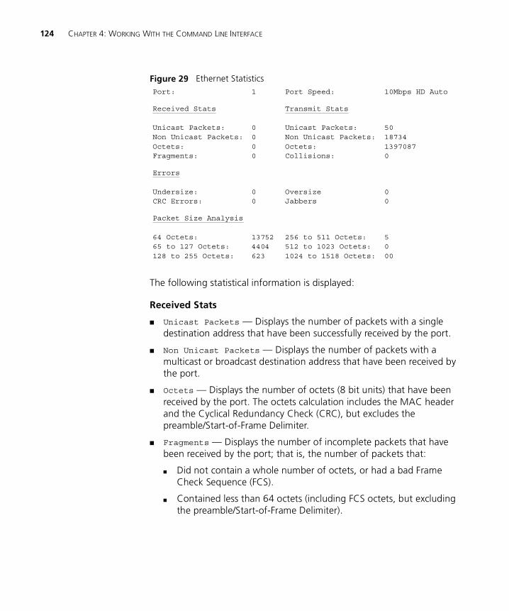
124 CHAPTER 4: WORKING WITH THE COMMAND LINE INTERFACE
Figure 29 Ethernet Statistics
The following statistical information is displayed:
Received Stats
� Unicast Packets — Displays the number of packets with a single destination address that have been successfully received by the port.
� Non Unicast Packets — Displays the number of packets with a multicast or broadcast destination address that have been received by the port.
� Octets — Displays the number of octets (8 bit units) that have been received by the port. The octets calculation includes the MAC header and the Cyclical Redundancy Check (CRC), but excludes the preamble/Start-of-Frame Delimiter.
� Fragments — Displays the number of incomplete packets that have been received by the port; that is, the number of packets that:
� Did not contain a whole number of octets, or had a bad Frame Check Sequence (FCS).
� Contained less than 64 octets (including FCS octets, but excluding the preamble/Start-of-Frame Delimiter).
Port: 1 Port Speed: 10Mbps HD Auto
Received Stats
Unicast Packets:Non Unicast Packets:Octets:Fragments:
0000
Transmit Stats
Unicast Packets:Non Unicast Packets:Octets:Collisions:
501873413970870
Errors
Undersize:CRC Errors:
00
OversizeJabbers
00
Packet Size Analysis
64 Octets:65 to 127 Octets:128 to 255 Octets:
137524404623
256 to 511 Octets:512 to 1023 Octets:1024 to 1518 Octets:
5000
Displaying and Changing Port Information 125
Transmitted Stats
� Unicast Packets — Displays the number of packets with a single destination address that have been transmitted by the port.
� Non Unicast Packets — Displays the number of packets with a multicast or broadcast destination address that have been successfully transmitted by the port.
� Octets — Displays the number of octets that have been transmitted by the port.
� Collisions — Displays an estimate of the total number of collisions that have occurred when the port was transmitting.
Errors
� Undersize — Displays the number of packets seen by the port that were smaller than the minimum size defined for IEEE 802.3 packets. Undersize packets may indicate externally generated interference causing problems on your network. Check your cabling routes, and re-route any cabling that may be affected by external sources.
� CRC Errors — Displays the number of packets seen by the port that contained a CRC error or an alignment error. A CRC error occurs if a packet of legal length has an invalid CRC but does not have a framing error. An alignment error occurs if a packet has a CRC error and does not contain a whole number of octets.
CRC and alignment errors may be caused by faults in transmitting devices. Change the Network Interface Card (NIC) of the device connected to the port. If this does not solve the problem, check your cables and connections for damage.
� Oversize — Displays the total number of packets seen by the port that exceed the maximum length defined for IEEE 802.3 packets. If you see a high number of oversize packets on your network, you need to isolate the source of these packets and examine the Network Interface Card of the device. Note that some protocols may generate oversize packets.
� Jabbers — Displays the total number of packets received on the port that were longer than 8000 octets (but including FCS octets, but excluding framing bits). Jabber is caused by faulty devices transmitting oversize packets continuously.
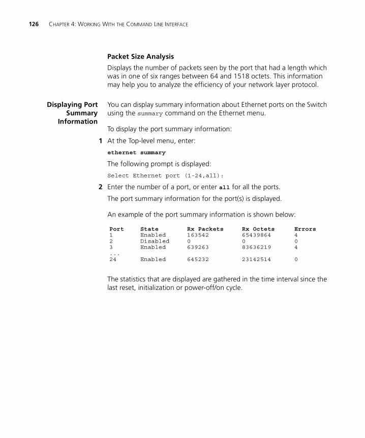
126 CHAPTER 4: WORKING WITH THE COMMAND LINE INTERFACE
Packet Size Analysis
Displays the number of packets seen by the port that had a length which was in one of six ranges between 64 and 1518 octets. This information may help you to analyze the efficiency of your network layer protocol.
Displaying PortSummary
Information
You can display summary information about Ethernet ports on the Switch using the summary command on the Ethernet menu.
To display the port summary information:
1 At the Top-level menu, enter:
ethernet summary
The following prompt is displayed:
Select Ethernet port (1-24,all):
2 Enter the number of a port, or enter all for all the ports.
The port summary information for the port(s) is displayed.
An example of the port summary information is shown below:
The statistics that are displayed are gathered in the time interval since the last reset, initialization or power-off/on cycle.
Port State Rx Packets Rx Octets Errors1 Enabled 163542 65439864 42 Disabled 0 0 03 Enabled 639263 83636219 4...24 Enabled 645232 23142514 0
Displaying and Changing System Feature Information 127
Displaying and Changing System Feature Information
You can display and change system feature information for the Switch units in the stack using the commands on the Feature menu. These commands allow you to:
� Set up Roving Port Analysis.
� Enable or disable Broadcast Storm Control.
� Set up Resilient Links.
� Set up Trunks.
Setting up a RovingAnalysis Port
You can set up the roving analysis port, that is the port that you wish to connect the network analyzer to, using the add command on the Analyzer menu.
You can not set up a port for roving analysis if it is already part of a resilient link, or a member of a trunk.
To set up a roving analysis port:
1 At the Top-level menu, enter:
feature analyzer add
The following prompt is displayed:
Select analysis unit (1-4):
2 Enter the number of the Switch unit in the stack on which you wish the roving analysis port to reside.
The following prompt is displayed:
Enter analysis port (3,6):
3 Enter the port number that you wish to be the roving analysis port. (The port selection list only includes the ports that are candidates to be the roving analysis port.)
Displaying the RovingAnalysis PortInformation
You can display information about the roving analysis port on the Switch using the display command on the Analyzer menu.
To display the port summary information:
1 At the Top-level menu, enter:
feature analyzer display
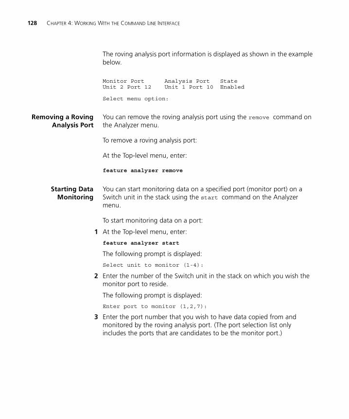
128 CHAPTER 4: WORKING WITH THE COMMAND LINE INTERFACE
The roving analysis port information is displayed as shown in the example below.
Removing a RovingAnalysis Port
You can remove the roving analysis port using the remove command on the Analyzer menu.
To remove a roving analysis port:
At the Top-level menu, enter:
feature analyzer remove
Starting DataMonitoring
You can start monitoring data on a specified port (monitor port) on a Switch unit in the stack using the start command on the Analyzer menu.
To start monitoring data on a port:
1 At the Top-level menu, enter:
feature analyzer start
The following prompt is displayed:
Select unit to monitor (1-4):
2 Enter the number of the Switch unit in the stack on which you wish the monitor port to reside.
The following prompt is displayed:
Enter port to monitor (1,2,7):
3 Enter the port number that you wish to have data copied from and monitored by the roving analysis port. (The port selection list only includes the ports that are candidates to be the monitor port.)
Monitor Port Analysis Port StateUnit 2 Port 12 Unit 1 Port 10 Enabled
Select menu option:
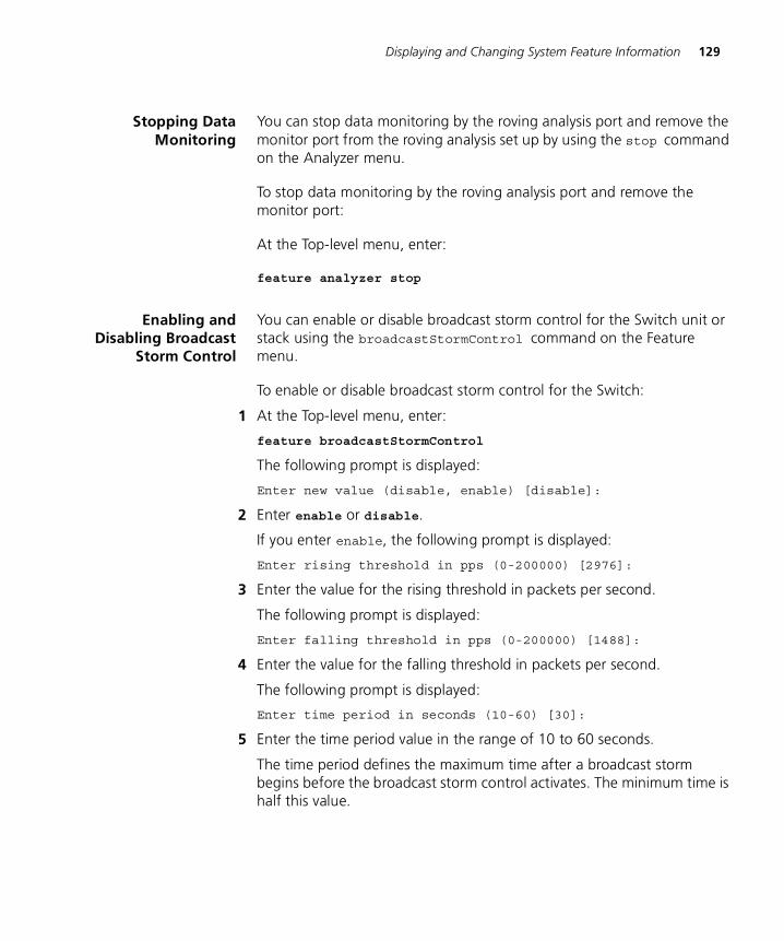
Displaying and Changing System Feature Information 129
Stopping DataMonitoring
You can stop data monitoring by the roving analysis port and remove the monitor port from the roving analysis set up by using the stop command on the Analyzer menu.
To stop data monitoring by the roving analysis port and remove the monitor port:
At the Top-level menu, enter:
feature analyzer stop
Enabling andDisabling Broadcast
Storm Control
You can enable or disable broadcast storm control for the Switch unit or stack using the broadcastStormControl command on the Feature menu.
To enable or disable broadcast storm control for the Switch:
1 At the Top-level menu, enter:
feature broadcastStormControl
The following prompt is displayed:
Enter new value (disable, enable) [disable]:
2 Enter enable or disable.
If you enter enable, the following prompt is displayed:
Enter rising threshold in pps (0-200000) [2976]:
3 Enter the value for the rising threshold in packets per second.
The following prompt is displayed:
Enter falling threshold in pps (0-200000) [1488]:
4 Enter the value for the falling threshold in packets per second.
The following prompt is displayed:
Enter time period in seconds (10-60) [30]:
5 Enter the time period value in the range of 10 to 60 seconds.
The time period defines the maximum time after a broadcast storm begins before the broadcast storm control activates. The minimum time is half this value.
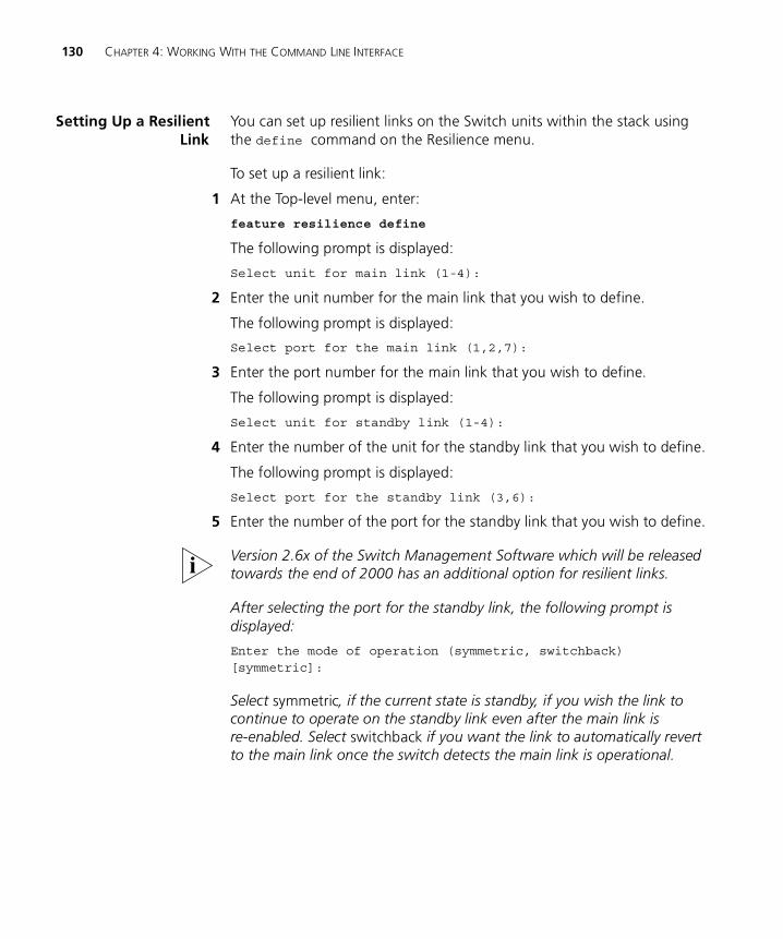
130 CHAPTER 4: WORKING WITH THE COMMAND LINE INTERFACE
Setting Up a ResilientLink
You can set up resilient links on the Switch units within the stack using the define command on the Resilience menu.
To set up a resilient link:
1 At the Top-level menu, enter:
feature resilience define
The following prompt is displayed:
Select unit for main link (1-4):
2 Enter the unit number for the main link that you wish to define.
The following prompt is displayed:
Select port for the main link (1,2,7):
3 Enter the port number for the main link that you wish to define.
The following prompt is displayed:
Select unit for standby link (1-4):
4 Enter the number of the unit for the standby link that you wish to define.
The following prompt is displayed:
Select port for the standby link (3,6):
5 Enter the number of the port for the standby link that you wish to define.
Version 2.6x of the Switch Management Software which will be released towards the end of 2000 has an additional option for resilient links.
After selecting the port for the standby link, the following prompt is displayed:
Enter the mode of operation (symmetric, switchback) [symmetric]:
Select symmetric, if the current state is standby, if you wish the link to continue to operate on the standby link even after the main link is re-enabled. Select switchback if you want the link to automatically revert to the main link once the switch detects the main link is operational.
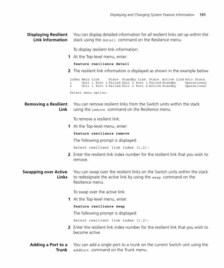
Displaying and Changing System Feature Information 131
Displaying ResilientLink Information
You can display detailed information for all resilient links set up within the stack using the detail command on the Resilience menu.
To display resilient link information:
1 At the Top-level menu, enter:
feature resilience detail
2 The resilient link information is displayed as shown in the example below.
Removing a ResilientLink
You can remove resilient links from the Switch units within the stack using the remove command on the Resilience menu.
To remove a resilient link:
1 At the Top-level menu, enter:
feature resilience remove
The following prompt is displayed:
Select resilient link index (1,2):
2 Enter the resilient link index number for the resilient link that you wish to remove.
Swapping over ActiveLinks
You can swap over the resilient links on the Switch units within the stack to redesignate the active link by using the swap command on the Resilience menu.
To swap over the active link:
1 At the Top-level menu, enter:
feature resilience swap
The following prompt is displayed:
Select resilient link index (1,2):
2 Enter the resilient link index number for the resilient link that you wish to become active.
Adding a Port to aTrunk
You can add a single port to a trunk on the current Switch unit using the addPort command on the Trunk menu.
Index Main Link State Standby Link State Active Link Pair State1 Unit 1 Port 1 Failed Unit 2 Port 1 Failed Standby Operational2 Unit 1 Port 6 Failed Unit 2 Port 6 Active Standby Operational
Select menu option:
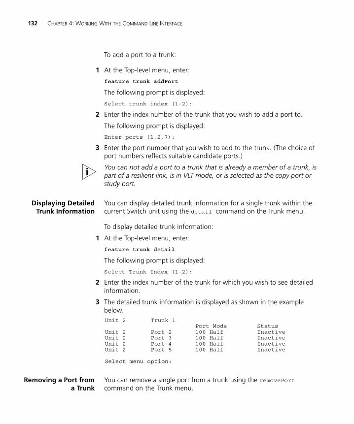
132 CHAPTER 4: WORKING WITH THE COMMAND LINE INTERFACE
To add a port to a trunk:
1 At the Top-level menu, enter:
feature trunk addPort
The following prompt is displayed:
Select trunk index (1-2):
2 Enter the index number of the trunk that you wish to add a port to.
The following prompt is displayed:
Enter ports (1,2,7):
3 Enter the port number that you wish to add to the trunk. (The choice of port numbers reflects suitable candidate ports.)
You can not add a port to a trunk that is already a member of a trunk, is part of a resilient link, is in VLT mode, or is selected as the copy port or study port.
Displaying DetailedTrunk Information
You can display detailed trunk information for a single trunk within the current Switch unit using the detail command on the Trunk menu.
To display detailed trunk information:
1 At the Top-level menu, enter:
feature trunk detail
The following prompt is displayed:
Select Trunk Index (1-2):
2 Enter the index number of the trunk for which you wish to see detailed information.
3 The detailed trunk information is displayed as shown in the example below.
Removing a Port froma Trunk
You can remove a single port from a trunk using the removePort command on the Trunk menu.
Unit 2 Trunk 1Port Mode Status
Unit 2 Port 2 100 Half InactiveUnit 2 Port 3 100 Half InactiveUnit 2 Port 4 100 Half InactiveUnit 2 Port 5 100 Half Inactive
Select menu option:
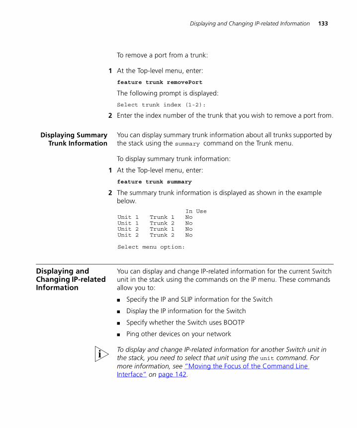
Displaying and Changing IP-related Information 133
To remove a port from a trunk:
1 At the Top-level menu, enter:
feature trunk removePort
The following prompt is displayed:
Select trunk index (1-2):
2 Enter the index number of the trunk that you wish to remove a port from.
Displaying SummaryTrunk Information
You can display summary trunk information about all trunks supported by the stack using the summary command on the Trunk menu.
To display summary trunk information:
1 At the Top-level menu, enter:
feature trunk summary
2 The summary trunk information is displayed as shown in the example below.
Displaying and Changing IP-related Information
You can display and change IP-related information for the current Switch unit in the stack using the commands on the IP menu. These commands allow you to:
� Specify the IP and SLIP information for the Switch
� Display the IP information for the Switch
� Specify whether the Switch uses BOOTP
� Ping other devices on your network
To display and change IP-related information for another Switch unit in the stack, you need to select that unit using the unit command. For more information, see “Moving the Focus of the Command Line Interface” on page 142.
In UseUnit 1 Trunk 1 NoUnit 1 Trunk 2 NoUnit 2 Trunk 1 NoUnit 2 Trunk 2 No
Select menu option:
134 CHAPTER 4: WORKING WITH THE COMMAND LINE INTERFACE
Specifying IP and SLIPInformation
You can specify IP and SLIP information for the current Switch unit in the stack using the define command on the IP/Interface menu.
To carry out this command for the first time after installing your switch, you need to connect a terminal or terminal emulator to the console port using a null modem cable. See “Setting Up Command Line Interface Management”on page 36 for more information about connecting to the console port.
To specify the IP and SLIP information:
1 At the Top-level menu, enter:
ip interface define
The following prompt is displayed, allowing you to enter an IP address for the Switch:
Enter IP address [0.0.0.0]:
For more information about IP addresses, see “IP Addresses” on page 38.
2 Enter a valid IP address.
The following prompt is displayed, allowing you to enter a subnet mask for the Switch:
Enter subnet mask [0.0.0.0]:
For more information about subnet masks, see “Subnets and Using a Subnet Mask” on page 39.
3 Enter a subnet mask, if required.
The following prompt is displayed, allowing you to enter the IP address of the default router in your network:
Enter default gateway [0.0.0.0]:
4 If your network contains a router, enter the IP address.
The following prompt is displayed:
Enter SLIP address [192.168.101.1]:
If you want to manage the stack using the web interface through the console port of the Switch, you need to set up Serial Line Interface Protocol (SLIP) information for the Switch. A SLIP address is similar to an IP address, but it is used for serial line connections to console ports. We recommend that you use the default address 192.168.101.1.
For more information, see “Serial Web Utility” on page 227.

Displaying and Changing IP-related Information 135
5 Enter a SLIP address, if required.
The following prompt is displayed:
Enter SLIP subnet mask [255.255.255.0]:
A SLIP subnet mask is an IP subnet mask that is used for serial line connections to console ports.
6 Enter a SLIP subnet mask, if required.
Displaying IP and SLIPInformation
You can display IP and SLIP information for the current Switch unit in the stack using the display command on the IP/Interface menu.
For more information about IP and SLIP, see “Managing a Switch Over the Network” on page 38.
To display the IP and SLIP information:
� At the Top-level menu, enter:
ip interface display
The IP and SLIP information for the Switch is displayed.
An example of the IP and SLIP information is shown below:
Enabling andDisabling BOOTP
If you have a BOOTP server on your network, you can use that server to allocate IP information for the Switch units in the stack automatically.
You can specify whether the Switch uses BOOTP by using the bootp command on the IP/Interface menu.
To specify that the Switch uses BOOTP:
1 At the Top-level menu, enter:
ip interface bootp
The following prompt is displayed:
Enter new value (enable, disable) [enable]:
2 Enter enable to specify that the Switch uses BOOTP, or disable to specify that it does not.
IP address 191.100.40.120Subnet mask: 255.255.0.0Default gateway: 191.100.40.121SLIP address: 191.100.40.120SLIP subnet mask 255.255.0.0
136 CHAPTER 4: WORKING WITH THE COMMAND LINE INTERFACE
In order for BOOTP to work, the IP configuration must be set to 0.0.0.0. Use the ip initializeConfig command to clear any existing IP configuration. For more information, see “Resetting the IP Configuration” on page 137.
After BOOTP is enabled, you need to power cycle the unit before BOOTP starts operating.
Pinging OtherDevices
The PING feature allows you to send out a PING request to test whether devices on an IP network are accessible and functioning correctly. This feature is useful for testing that the stack is installed and set up correctly, and that your network connections are working.
You can PING other devices on your network using the ping command on the IP menu.
To PING a device:
1 At the top-level menu, enter:
ip ping
The following prompt is displayed:
Enter destination IP address:
2 Enter the IP address of the device that you want to PING.
The stack sends a single PING request to the specified device and a message similar to the following is displayed:
Starting ping, resolution of displayed time is 10 milli-sec
If the device is accessible and functioning correctly, a message similar to the following is displayed:
response from 191.128.40.121: 3 router hops. time = 10ms
If the device is not accessible, or is not functioning correctly, a message similar to the following is displayed:
No answer from 191.128.40.121
Displaying and Changing SNMP-related Information 137
Resetting the IPConfiguration
You can reset the IP configuration information for the whole stack back to factory defaults.
To do this:
1 At the top-level menu, enter:
ip initializeConfig
The following warning is displayed:
WARNING: This change will lock out all SNMP, Telnet and Web based management access.
Do you wish to continue (yes/no) [no]:
2 Enter yes to reset the IP configuration.
Displaying and Changing SNMP-related Information
You can display and change SNMP-related information for the stack using the commands on the SNMP menu. These commands allow you to:
� Specify SNMP community strings for the stack
� Specify the trap destination details for the stack
� Display the trap destination details for the stack
� Modify trap destination details for the stack
� Remove trap destination details for the stack
� Perform an SNMP GET command on the stack
� Perform an SNMP GETNEXT command on the stack
� Perform an SNMP SET command on the stack
Specifying SNMPCommunity Strings
You can specify SNMP community strings for the users defined on the stack using the community command on the SNMP menu.
By default, all users have a community string that is identical to the user name. For example, the community string for the user monitor is monitor.
To specify the SNMP community strings:
1 At the Top-level menu, enter:
snmp community
The following prompt is displayed:
Enter new community for user ‘<user>’:
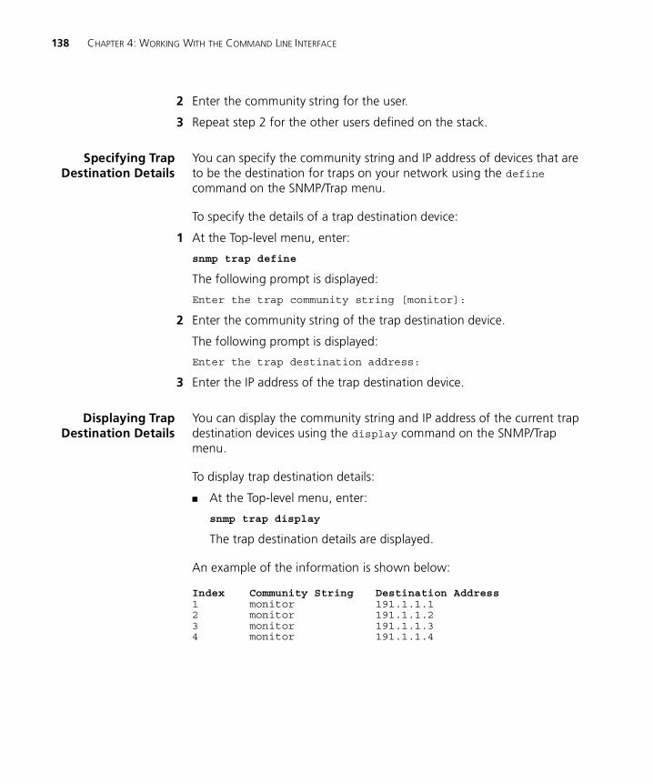
138 CHAPTER 4: WORKING WITH THE COMMAND LINE INTERFACE
2 Enter the community string for the user.
3 Repeat step 2 for the other users defined on the stack.
Specifying TrapDestination Details
You can specify the community string and IP address of devices that are to be the destination for traps on your network using the define command on the SNMP/Trap menu.
To specify the details of a trap destination device:
1 At the Top-level menu, enter:
snmp trap define
The following prompt is displayed:
Enter the trap community string [monitor]:
2 Enter the community string of the trap destination device.
The following prompt is displayed:
Enter the trap destination address:
3 Enter the IP address of the trap destination device.
Displaying TrapDestination Details
You can display the community string and IP address of the current trap destination devices using the display command on the SNMP/Trap menu.
To display trap destination details:
� At the Top-level menu, enter:
snmp trap display
The trap destination details are displayed.
An example of the information is shown below:
Index Community String Destination Address1 monitor 191.1.1.12 monitor 191.1.1.23 monitor 191.1.1.34 monitor 191.1.1.4
Displaying and Changing SNMP-related Information 139
Modifying TrapDestination Details
You can modify the community string and IP address of a current trap destination device using the modify command on the SNMP/Trap menu.
To modify trap destination details:
1 At the Top-level menu, enter:
snmp trap modify
The following prompt is displayed:
Select trap index (1,2,3):
2 Enter the index number of the trap destination device to be modified.
The following prompt is displayed:
Enter the trap community string [monitor]:
3 Enter the new community string of the trap destination device.
The following prompt is displayed:
Enter the trap destination address [<ip address>]:
4 Enter the new IP address of the trap destination device.
Removing TrapDestination Details
You can remove the details of a current trap destination device using the remove command on the SNMP/Trap menu.
To remove trap destination details:
1 At the Top-level menu, enter:
snmp trap remove
The following prompt is displayed:
Select trap index (1,2,3,all):
2 Enter the index number of the trap destination device that is to have its details removed, or enter all to remove all trap destination device details.
Performing an SNMPGET Command
An SNMP GET command allows you to retrieve values of SNMP objects from a network device. You can perform an SNMP GET command on the stack using the get command on the SNMP menu.
To perform an SNMP GET command on the stack:
1 At the Top-level menu, enter:
snmp get
The following prompt is displayed:
Enter object-identifier:
140 CHAPTER 4: WORKING WITH THE COMMAND LINE INTERFACE
2 Enter the identifier of the SNMP object.
The following prompt is displayed:
Enter type (phys,ip,gauge,cnt,num,str)[str]:
3 Enter the data type of the SNMP object.
The value of the SNMP object is displayed.
Performing an SNMPGETNEXT Command
An SNMP GET NEXT command allows you to specify an SNMP object in a network device and then retrieve information about the next few SNMP objects in the device. You can perform an SNMP GET NEXT command on the stack using the next command on the SNMP menu.
To perform an SNMP GETNEXT command on the stack:
1 At the Top-level menu, enter:
snmp next
The following prompt is displayed:
Enter object-identifier:
2 Enter the identifier of an SNMP object.
The following prompt is displayed:
Enter count:
3 Enter the number of SNMP objects after the object specified for which you want to retrieve information.
The SNMP object information is displayed.
Performing an SNMPSET Command
An SNMP SET command allows you to modify values of SNMP objects in a network device. You can perform an SNMP SET command on the stack using the set command on the SNMP menu.
CAUTION: You should not modify the values of SNMP objects unless you have considerable knowledge and experience with SNMP.
To perform an SNMP SET command on the stack:
1 At the Top-level menu, enter:
snmp set
The following prompt is displayed:
Enter object-identifier:

Displaying and Changing Stack Information 141
2 Enter the identifier of the SNMP object.
The following prompt is displayed:
Enter type (phys,ip,gauge,cnt,num,str)[str]:
3 Enter the data type of the SNMP object.
The following prompt is displayed:
Enter value:
4 Enter the new value of the SNMP object.
Displaying and Changing Stack Information
You can display and change information about the Switch units in the stack or the stack as a whole using the commands on the System menu. These commands allow you to:
� Move the focus of the command line interface from one Switch unit in the stack to another
� Specify administration details for the stack
� Display administration details for the current Switch unit in the stack
� Display summary information about the Switch units in the stack
� Change the password for the current user
� Specify, display, modify and remove user details for the stack
� Display and modify the access rights for the access levels in the stack
� Enable and disable all forms of remote access to the stack
� Reset the Switch units in the stack
� Initialize the Switch units in the stack
� Upgrade the management software of the Switch units in the stack
� Configure intelligent modules in the stack.
142 CHAPTER 4: WORKING WITH THE COMMAND LINE INTERFACE
Moving the Focus ofthe Command Line
Interface
Many commands in the command line interface perform their actions on a single Switch unit in the stack — the current Switch. You can move the focus of the command line interface from one unit in the stack to another using the unit command on the System menu.
To move the focus:
1 At the Top-level menu, enter:
system unit
The following prompt is displayed, allowing you to enter a unit number:
Select unit [1]:
2 Enter the number of the unit to be managed.
You can have up to four Switch units in a stack:
� If the stack contains one unit, that unit is unit 1.
� If the stack contains two units connected using a Matrix Cable, the unit with the lowest MAC address is unit 1 and the other unit is unit 2.
� If the stack contains a number of units connected using a Matrix Module, the unit numbers are defined by the port connections on the Module.
Returning the Focus to the Previous Switch Unit
You can return the focus of the command line interface to the previous Switch unit in the stack using the logout command on the System menu.
Specifying StackAdministration
Details
You can specify administration details (system name, contact name, and physical location) for the stack using the information command on the System menu.
To specify the administration details:
1 From the Top-level menu, enter:
system information
The following prompt is displayed:
Enter system name [<system name>]:
2 Enter a system name, or descriptive name, for the stack. The name can be up to 20 characters long.
The following prompt is displayed:
Enter system contact [<contact name>]:
Displaying and Changing Stack Information 143
3 Enter the details of a person to contact about the stack.
The following prompt is displayed:
Enter system location [<location>]:
4 Enter a physical location for the stack.
Displaying SwitchAdministration
Details
You can display the administration details for the current Switch unit in the stack using the display command on the System menu. This information may be useful for your technical support representative if you have a problem.
To display the information:
� From the Top-level menu, enter:
system display
The administration details are displayed.
An example of the details is shown below. Some fields are only displayed after a software upgrade failure and these provide information about the software upgrade.
The following read-only fields are displayed:
System NameDisplays the descriptive name, or system name, for the unit. For information about assigning a new name, see “Specifying Stack Administration Details” on page 142.
3Com SuperStack 3System Name: DevelopmentLocation: Wiring Closet, Floor 1Contact: System Administrator
Time since reset: 2 days, 3 hours, 10 minutesOperational Version: 2.20Hardware Version 1Boot Version: 1.00MAC Address: 08:00:00:00:11:11Product No. 3C33000Serial Number 7ZNR001111
TFTP Server Address 161.71.120.152Filename s2s02_50.binLast software upgrade TFTP Access Violation
144 CHAPTER 4: WORKING WITH THE COMMAND LINE INTERFACE
LocationDisplays the physical location of the unit. For information about assigning a new location, see “Specifying Stack Administration Details” on page 142.
ContactDisplays the details of a person to contact about the stack. For information about assigning new contact details, see “Specifying Stack Administration Details” on page 142.
Time Since ResetDisplays the time that has elapsed since the unit was last reset, initialized or powered-up.
Operational VersionDisplays the version number of the management software currently installed on the unit. For information about how to upgrade the management software, see “Upgrading Management Software” on page 153.
Hardware VersionDisplays the version number of the unit hardware.
Boot VersionDisplays the version of Boot PROM software installed on the unit.
MAC AddressDisplays the MAC (Ethernet) address of the unit.
Product NumberDisplays the 3Com product number of the unit.
Serial NumberDisplays the serial number of the unit.
TFTP Server (optionally displayed)Displays the IP address of the last TFTP server used to upgrade the unit’s management software.
Filename (optionally displayed)Displays the name of the management software file that was used during the last software upgrade attempt.
Software Upgrade Status (optionally displayed)Displays the reason for a software upgrade failure.
Displaying and Changing Stack Information 145
Displaying StackSummary
Information
You can display summary information about the Switch units in the stack using the inventory command on the System menu.
To display the information:
� From the Top-level menu, enter:
system inventory
The summary information is displayed.
An example of the summary information is shown below:
The following read-only fields are displayed:
PositionDisplays the number of the unit in the stack.
You can have up to four Switch units in a stack:
� If the stack contains one unit, that unit is unit 1.
� If the stack contains two units connected using a Matrix Cable, the unit with the lowest MAC address is unit 1 and the other unit is unit 2.
� If the stack contains a number of units connected using a Matrix Module, the unit numbers are defined by the port connections on the Module.
DescriptionDisplays the product name of the unit.
Unit NameDisplays the descriptive name, or system name, for the unit. For information about assigning a new name, see “Specifying a Descriptive Name” on page 67.
StateDisplays the current operating state of the unit:
� Operational — The unit is operating normally.
� Loading — A process taking place on the unit, for example a software upgrade.
Position Description Unit Name State1 Switch 1100 26 Accounts Operational2 Switch 3300 24 Development Operational3 Switch 1100 14 Accounts Loading4 Switch 3300 12 Accounts Operational
146 CHAPTER 4: WORKING WITH THE COMMAND LINE INTERFACE
ConfiguringIntelligent Modules
You can configure intelligent modules such as the Switch Layer 3 Module and the Switch ATM Expansion module.
Setting Module Configuration
You can set the IP configuration for an intelligent module using the define command on the Module menu. To set the IP configuration for the Module:
1 At the top-level menu, enter:
system module define
The following prompt is displayed:
Enter IP Address [0.0.0.0]:
2 Enter the IP address for the module.
The following prompt is displayed:
Enter subnet mask [xxx.xxx.xxx.xxx]:
3 Enter the subnet mask for the module.
The following prompt is displayed:
Enter default router [0.0.0.0]:
4 Enter the default router for the module.
The new addresses are displayed before exiting.
Displaying Module Configuration
You can display the configuration of a module using the display command on the System Module menu.
At the top-level menu, enter:
system module display
The intelligent module configuration details are displayed.
Enabling and Disabling the Module Interface
You can enable or disable the intelligent module using the mode command on the System Module menu. To do this:
1 At the top-level menu, enter:
system module mode
The following prompt is displayed:
Enter new value (enable, disable) [enable]:
2 Enter enable or disable.
Displaying and Changing Stack Information 147
Changing YourPassword
You can change the password for the current user using the password command on the System menu.
To change the password:
1 At the Top-level menu, enter:
system password
The following prompt appears, allowing you to enter the existing password:
old password
2 Enter the existing password.
The following prompt is displayed, allowing you to enter a new password for the current user:
Enter new password
3 Enter the new password.
Passwords must only contain alpha-numeric characters.
The following prompt is displayed, allowing you to re-enter the new password as conformation:
Retype password:
A message is displayed informing you that the password has been successfully changed.
Specifying UserDetails
You can specify user details for the stack using the define command on the System/Security/User menu.
To specify user details for the stack:
1 From the Top-level menu, enter:
system security user define
The following prompt is displayed:
Enter a new user name:
2 Enter a name for the new user.
The following prompt is displayed:
Enter the access level (monitor,manager,security) [security]:
3 Enter an access level for the new user.
The following prompt is displayed:
Enter the password:

148 CHAPTER 4: WORKING WITH THE COMMAND LINE INTERFACE
4 Enter a password for the new user.
The following prompt is displayed:
Re-enter the password:
5 Enter the password for the new user again.
The following prompt is displayed:
Enter the community string [<user>]:
6 Enter a community string for the new user.
Displaying UserDetails
You can display the user details for the stack using the display command on the System/Security/User menu.
To display the user details for the stack:
� From the Top-level menu, enter:
system security user display
The user details are displayed.
An example of the details is shown below:
Modifying UserDetails
You can modify user details for the stack using the modify command on the System/Security/User menu.
To modify user details for the stack:
1 From the Top-level menu, enter:
system security user modify
The following prompt is displayed:
Enter the user name:
2 Enter the name of the user to be modified.
The following prompt is displayed:
Enter the password:
Name Access Level Community Stringadmin security adminmanager manager managermonitor monitor monitorsecurity security security
Displaying and Changing Stack Information 149
3 Enter a password for the user.
The following prompt is displayed:
Re-enter the password:
4 Enter the password for the user again.
The following prompt is displayed:
Enter the community string [<user>]:
5 Enter a community string for the user.
Removing UserDetails
You can remove user details from the stack using the remove command on the System/Security/User menu.
To remove user details from the stack:
1 From the Top-level menu, enter:
system security user remove
The following prompt is displayed:
Enter the user name (<users>,all):
2 Enter the name of the user that is to have its details removed, or enter all to remove the details of all users (except default users).
Displaying AccessRights
You can display the access rights for all access levels in the stack using the display command on the System/Security/Access menu.
To display the access rights for the stack:
� From the Top-level menu, enter:
system security access display
The access rights are displayed.
An example of the access rights information is shown below:
Access Level SNMP Console Telnet Webmonitor enable enable enable enablemanager enable enable enable enablesecurity enable enable enable enable
150 CHAPTER 4: WORKING WITH THE COMMAND LINE INTERFACE
Modifying AccessRights
You can modify access rights for the access levels in the stack using the modify command on the System/Security/Access menu.
To modify the access rights for the stack:
1 From the Top-level menu, enter:
system security access modify
The following prompt is displayed:
Enter access level (monitor,manager,security):
2 Enter the access level to be modified.
The following prompt is displayed:
Enter new value for SNMP (enable,disable) [enable]:
3 Enter enable if the access level allows SNMP management, or disable if it does not.
The following prompt is displayed:
Enter new value for console (enable,disable) [enable]:
4 Enter enable if the access level allows management through a console port of the stack, or disable if it does not.
The following prompt is displayed:
Enter new value for telnet (enable,disable) [enable]:
5 Enter enable if the access level allows telnet management, or disable if it does not.
The following prompt is displayed:
Enter new value for web (enable,disable) [enable]:
6 Enter enable if the access level allows web management, or disable if it does not.

Displaying and Changing Stack Information 151
Enabling andDisabling Remote
Access
As a basic security measure, you can enable or disable remote access to the management software of the stack:
� When remote access is enabled, you can access the management software using all management methods.
� When remote access is disabled:
� Users cannot access the stack over the network using the command line interface.
� Users cannot access the stack over the network using the web interface.
� Users cannot access the Switch using an SNMP Network Manager.
� Users can only access the command line interface or web interface using a direct connection to the console port of a Switch unit in the stack.
You can enable or disable remote access to the management software of the stack using the remoteAccess command on the System menu.
To enable or disable remote access:
1 At the Top-level menu, enter:
system remoteAccess
2 The following prompt is displayed:
Enter new value (enable,disable) [enable]:
3 Enter enable or disable as required.
Resetting All theUnits in the Stack
You can reset all the Switch units in the stack using the reset command on the System menu.
To reset the units:
1 At the Top-level menu, enter:
system reset
The following prompt is displayed:
Are you sure you want to reset the system (y/n) [y]:
2 Enter y if you wish to proceed, or n if you want to stop the reset.
152 CHAPTER 4: WORKING WITH THE COMMAND LINE INTERFACE
What Happens During a Reset?
Resetting the Switch units in the stack simulates a power-off/on cycle. You may want to do this if you need to:
� Remove all the Learned entries in the Switch Database (SDB).
� Reset the statistic counters of the stack.
CAUTION: Resetting the stack causes some of the traffic being transmitted over the network to be lost. It also clears all Learned entries from the Switch Database.
The stack takes about 10 seconds to reset. While the stack is resetting, you cannot communicate with it.
Initializing All theUnits in the Stack
You can initialize all the Switch units in the stack using the initialize command on the System menu.
To initialize the units:
1 At the top-level menu, enter:
system initialize
The following prompt is displayed:
Initializes the system to factory defaults and causes a reset.Do you wish to continue (yes,no) [no]:
2 Enter y if you wish to proceed, or n if you want to stop the initialization.
What Happens During an Initialization?
Initializing the Switch units in the stack returns them to their default (factory) settings. The only information that does not return to its default setting is the IP and SLIP information, which is retained to ensure that you can continue managing the stack. You may want to initialize the stack if it has previously been used in a different part of your network, and its settings are incorrect for the new environment.
CAUTION: Use great care when initializing the stack — it removes all configuration information, including password and security information.
CAUTION: When initializing the stack, network loops may occur if you have set up port trunks, resilient links, VLANs, or the Spanning Tree
Displaying and Changing Stack Information 153
Protocol. Before initializing the stack, ensure you have disconnected the cabling for all standby or duplicate links.
The stack takes about 10 seconds to initialize. While the stack is initializing, you cannot communicate with it.
UpgradingManagement
Software
You can upgrade the management software of all Switch units in the stack using the softwareUpgrade command on the System menu.
To upgrade the management software:
1 Copy the software upgrade file into an appropriate directory on a TFTP server. For information on using a TFTP Server, see the documentation that accompanies it.
CAUTION: You must ensure that the port connected to the TFTP server has 802.1Q VLAN learning disabled and belongs to the Default VLAN (VLAN 1). The server can only upgrade a stack if it is connected to the stack by the Default VLAN.
You can download a TFTP server called 3CServer (filename: 3cs117.zip) from the 3Com website http://www.3com.com. 3CServer can be installed and run on a Microsoft Windows® 95/98 or NT system.
2 From the Top-level menu, enter:
system softwareUpgrade
The following prompt is displayed:
TFTP Server Address [0.0.0.0]:
3 Enter the IP address of the TFTP server that holds the software upgrade file. The file must be stored somewhere that is accessible to the TFTP load request. Contact your system administrator if you are unsure where to place the image file.
The following prompt is displayed:
File name []:
4 Enter the name of the software upgrade file. The filename format is:
s2sxx_yy.bin
where xx_yy is the version of management software.
CAUTION: You must use the s2sxx_yy.bin format, otherwise the upgrade fails.
154 CHAPTER 4: WORKING WITH THE COMMAND LINE INTERFACE
During the upgrade, the Power/Self Test LED flashes green and the command line interface is locked. The units in the stack upgrade one at a time, and each unit takes about 5 minutes; when the upgrade is complete, the Switch units in the stack are reset.
CAUTION: During the upgrade, do not power-down or reset any Switch units in the stack.
A power interrupt during the software ipgrade may cause a corrupted agent image on the switch. If this occurs then subsequent rebooting of the switch will be unsuccessful. The front panel LEDs 2 and 3 will be lit and the Power LED will flash. If this happens, the software agent must be upgraded using a serial upgrade. For more information, see Appendix A.

III
MANAGEMENT REFERENCEChapter 5 Port Trunks
Chapter 6 Virtual LANs (VLANs)
Chapter 7 FastIP
Chapter 8 Multicast Filtering
Chapter 9 Spanning Tree Protocol
Chapter 10 RMON


5
PORT TRUNKSPort trunks are connections that allow devices to communicate using up to four links in parallel.
This chapter explains more about port trunks and how to set them up on your network. It covers the following topics:
� What are Port Trunks?
� Port Trunks and Your Switch
� Placing Ports in a Port Trunk
� Port Trunk Example
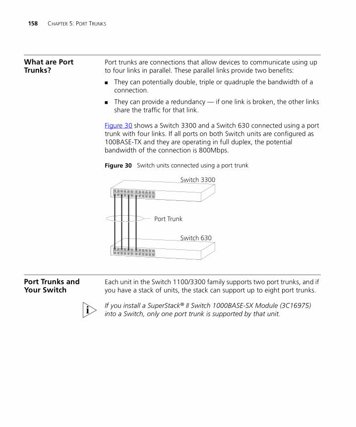
158 CHAPTER 5: PORT TRUNKS
What are Port Trunks?
Port trunks are connections that allow devices to communicate using up to four links in parallel. These parallel links provide two benefits:
� They can potentially double, triple or quadruple the bandwidth of a connection.
� They can provide a redundancy — if one link is broken, the other links share the traffic for that link.
Figure 30 shows a Switch 3300 and a Switch 630 connected using a port trunk with four links. If all ports on both Switch units are configured as 100BASE-TX and they are operating in full duplex, the potential bandwidth of the connection is 800Mbps.
Figure 30 Switch units connected using a port trunk.
Port Trunks and Your Switch
Each unit in the Switch 1100/3300 family supports two port trunks, and if you have a stack of units, the stack can support up to eight port trunks.
If you install a SuperStack® II Switch 1000BASE-SX Module (3C16975) into a Switch, only one port trunk is supported by that unit.

Placing Ports in a Port Trunk 159
When setting up a port trunk, note that:
� The ports at both ends of a connection must be configured as trunk ports.
� The trunk ports can only belong to one port trunk.
� The trunk ports must be fiber or twisted pair ports.
� The trunk ports must be from the same Switch in the stack.
� The trunk ports must have an identical configuration. Port speed is the only exception — if ports of a different speed are trunked together, the higher speed links carry the traffic. The lower speed links only carry the traffic if the higher speed links fail.
� The ports in a trunk do not support security, VLT tagging, resilient links, or roving analysis. For information about security, see “Configuring a Port” on page 59. For information about VLT tagging, see “Placing a Port in Multiple VLANs” on page 166. For information about resilient links, see “Setting Up Resilient Links” on page 79. For information about roving analysis, see “Setting Up Roving Analysis Ports” on page 86.
� Port trunks cannot have a permanent entry placed against them in the Switch Database.
When using a port trunk, note that:
� To gather statistics about a port trunk, you must add together the statistics for each port in the trunk.
� To disable a link in a port trunk, you must remove the connection and then disable both trunk ports in the link separately. If you do this, the traffic destined for that link is distributed to the other links in the port trunk. If you do not remove the connection and only disable one trunk port in the link, traffic is still forwarded to that port by the trunk port at the other end. This means that a significant amount of traffic may be lost.
� Before removing a port trunk, you must disable all the trunk ports or disconnect all the links — if you do not, a loop may be created.
Placing Ports in a Port Trunk
To place ports into a port trunk, use the Port Trunk Setup page of the web interface; for more information, see “Setting Up Port Trunks” on page 81.
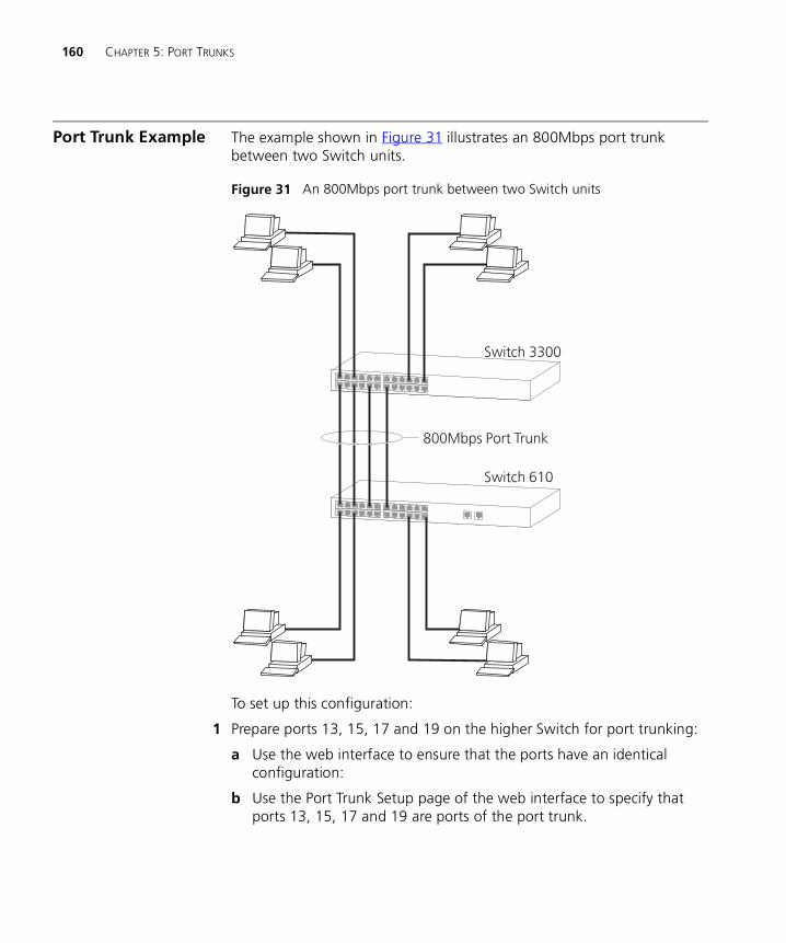
160 CHAPTER 5: PORT TRUNKS
Port Trunk Example The example shown in Figure 31 illustrates an 800Mbps port trunk between two Switch units.
Figure 31 An 800Mbps port trunk between two Switch units
To set up this configuration:
1 Prepare ports 13, 15, 17 and 19 on the higher Switch for port trunking:
a Use the web interface to ensure that the ports have an identical configuration:
b Use the Port Trunk Setup page of the web interface to specify that ports 13, 15, 17 and 19 are ports of the port trunk.

Port Trunk Example 161
2 Prepare ports 1, 3, 5 and 7 on the lower Switch for port trunking:
a Use the web interface to ensure that the ports have an identical configuration:
b Use the Port Trunk Setup page of the web interface to specify that ports 1, 3, 5 and 7 are ports of the port trunk.
3 Connect port 13 on the higher Switch to port 1 on the lower Switch.
4 Connect port 15 on the higher Switch to port 3 on the lower Switch.
5 Connect port 17 on the higher Switch to port 5 on the lower Switch.
6 Connect port 19 on the higher Switch to port 7 on the lower Switch.

162 CHAPTER 5: PORT TRUNKS
6
VIRTUAL LANS (VLANS)Setting up Virtual Local Area Networks (VLANs) on your Switch reduces the time and effort required by many network administration tasks, and increases the efficiency of your network.
This chapter explains more about the concept of VLANs and explains how they can be implemented on your Switch. It covers the following topics:
� What are VLANs?
� Benefits of VLANs
� VLANs and Your Switch
� VLAN Configuration for Beginners
164 CHAPTER 6: VIRTUAL LANS (VLANS)
What are VLANs? A VLAN is a flexible group of devices that can be located anywhere in a network, but they communicate as if they are on the same physical segment. With VLANs, you can segment your network without being restricted by physical connections — a drawback of traditional network design. As an example, with VLANs you can segment your network according to:
� Departmental groups — For example, you can have one VLAN for the Marketing department, another for the Finance department, and another for the Development department.
� Hierarchical groups — For example, you can have one VLAN for directors, another for managers, and another for general staff.
� Usage groups — For example, you can have one VLAN for users of e-mail, and another for users of multimedia.
Benefits of VLANs The main benefit of VLANs is that they provide a network segmentation system that is far more flexible than any traditional network. Using VLANs also provides you with three other benefits:
� It eases the change and movement of devices on IP networks
With traditional IP networks, network administrators spend much of their time dealing with moves and changes. If users move to a different IP subnet, the IP addresses of each endstation must be updated manually.
With a VLAN setup, if an endstation in VLAN 1 is moved to a port in another part of the network, you only need to specify that the new port forwards VLAN 1 traffic.
� It provides extra security
Devices within each VLAN can only communicate directly with devices in the same VLAN. If a device in VLAN 1 needs to communicate with devices in VLAN 2, the traffic needs to pass through a routing device or Layer 3 switch.
� It helps to control broadcast traffic
With traditional networks, congestion can be caused by broadcast traffic that is directed to all network devices whether they require it or not. VLANs increase the efficiency of your network because each VLAN can be set up to contain only those devices that need to communicate with each other.
VLANs and Your Switch 165
VLANs and Your Switch
Your Switch provides the following VLAN features:
� Support for up to 16 VLANs using the IEEE 802.1Q standard
The IEEE 802.1Q standard allows each port on your Switch to:
� Be placed in any single VLAN defined on the Switch.
� Be placed in several VLANs at the same time using 802.1Q tagging.
� Use 802.1Q learning — A system that uses the GARP VLAN Registration Protocol (GVRP) to enable the Switch to learn the VLAN requirements of the endstations attached to each port, and place the relevant ports in those VLANs automatically.
� Forward traffic for VLANs that are unknown to the Switch.
The standard requires that you define the following information about each VLAN on your Switch before the Switch can use it to forward traffic:
� VLAN Name — This is a descriptive name for the VLAN (for example, Marketing or Management).
� 802.1Q VLAN ID — This is used to identify the VLAN if you use 802.1Q tagging across your network.
� Local ID — This is used to identify the VLAN within the Switch, and corresponds to the VLAN IDs used in legacy 3Com devices.
� Support for VLT tagging
VLT (Virtual LAN Trunk) tagging is a proprietary 3Com system that allows a port to be placed in all the VLANs defined for your Switch.
The Default VLAN A new or initialized Switch contains a single VLAN, the Default VLAN. This VLAN has the following definition:
� VLAN Name — Default VLAN
� 802.1Q VLAN ID — 1
� Local ID — 1
All the ports are initially placed in this VLAN, and it is the only VLAN that allows you to access the management software of the Switch over the network.
166 CHAPTER 6: VIRTUAL LANS (VLANS)
Defining New VLANs If you want to move a port from the Default VLAN to another VLAN, you must first define information about the new VLAN on your Switch. To do this, you use the VLAN Setup page of the web interface; see “Defining VLAN Information” on page 84.
Untagged andTagged VLANs
When setting up VLANs you need to understand when to use untagged and tagged VLANs. Quite simply, if a port is in a single VLAN it can be untagged but if the port needs to be a member of multiple VLANs it must be tagged.
The IEEE 802.1Q standard defines how VLANs operate within an open packet-switched network. An 802.1Q compliant packet carries additional information that allows a switch to determine to which VLAN the port belongs. If a frame is carrying the additional data, it is known as tagged.
To carry multiple VLANs across a single physical (backbone) link, each packet must be tagged with a VLAN identifier so that the switches can identify which packets belong in which VLANs. Routers interconnect VLANs, so they must also understand 802.1Q tagging, so that they do not become bottlenecks for inter-VLAN traffic.
Placing a Port in aSingle VLAN
Once the information for a new VLAN has been defined, you can place a port in that VLAN. To do this, use the Untagged VLAN listbox on the Port Setup page of the web interface; see “Configuring a Port” on page 59.
Placing a Port inMultiple VLANs
Your Switch supports VLAN tagging, a system that allows traffic for multiple VLANs to be carried on a single link. Two methods of VLAN tagging are supported: 802.1Q tagging and VLT (Virtual LAN Trunk) tagging.
802.1Q Tagging
This method of tagging is defined in the IEEE 802.1Q standard, and allows a link to carry traffic for any of the VLANs defined on your Switch. 802.1Q tagging can only be used if the devices at both ends of a link support IEEE 802.1Q.
VLANs and Your Switch 167
To create an 802.1Q tagged link:
1 Ensure that the device at the other end of the link uses the same 802.1Q tags as your Switch.
2 Place the Switch port in the required VLANs using the VLAN Setup page of the web interface; see “Placing Ports in Multiple VLANs Using 802.1Q Tagging” on page 85.
3 Place the port at the other end of the link in the same VLANs as the port on your Switch.
You cannot create an 802.1Q tagged link with ports that already use VLT tagging (see “VLT Tagging” below).
VLT Tagging
This method of tagging is a proprietary system developed by 3Com, and allows a link to carry traffic for all the VLANs defined on your Switch. VLT tagging can only be used on links to legacy 3Com devices.
To create a VLT tagged link:
1 Specify that the port is a VLT port using the VLT listbox on the Port Setup page of the web interface; see “Configuring a Port” on page 59.
2 Specify that the port at the other end of the link is a VLT port.
You cannot create a VLT tagged link with ports that already use 802.1Q tagging.
A VLT tagged link only carries traffic for VLANs defined on your Switch. In legacy 3Com devices, a VLT tagged link carries traffic for all VLANs automatically.
Using IEEE 802.1QLearning
If an endstation supports IEEE 802.1Q, it can be configured to inform your network that it is to receive traffic for specific VLANs. If your Switch units have IEEE 802.1Q learning enabled, they can do the following:
� Automatically place the endstation in those VLANs.
� Automatically ensure that the required VLAN traffic can always reach the endstation from anywhere in the network.
IEEE 802.1Q VLAN Learning (GVRP) only works correctly in networks that have 16 or less 802.1Q VLANs.
168 CHAPTER 6: VIRTUAL LANS (VLANS)
The system works as follows:
1 The configured 802.1Q endstation sends out a packet with a known multicast address to the whole network — this packet declares that the endstation is to receive traffic for specific VLANs.
2 When the packet arrives at a port on a Switch with 802.1Q learning enabled, the Switch places the receiving port in the VLANs specified and then forwards the packet to all other ports.
3 When the packet arrives at another Switch with 802.1Q learning enabled, it also places the receiving port in the VLANs specified and forwards the packet to all other ports. In this way the VLAN information is propagated throughout the network, and the required VLAN traffic can always reach the endstation from anywhere in the network.
For information about enabling 802.1Q learning for an individual port on your Switch, see “Configuring a Port” on page 59. For information about enabling 802.1Q learning for a whole Switch or stack, see “Configuring the Advanced Stack Settings” on page 76.
For information about configuring IEEE 802.1Q functionality on an endstation, refer to the user documentation supplied with your endstation or the endstation’s Network Interface Card (NIC).
Forwarding TrafficContaining Unknown
802.1Q Tags
Your Switch supports up to 16 VLANs, however the IEEE 802.1Q standard allows up to 4,094 VLANs to be defined on a network. If your network contains endstations that support 802.1Q, the Switch may need to forward traffic that uses unknown 802.1Q tags. This traffic is automatically forwarded if your Switch has 802.1Q learning enabled, but is not if 802.1Q learning is disabled.
To specify that a port can forward traffic containing unknown tags when 802.1Q learning is disabled, see “Configuring a Port” on page 59. We recommend that you only forward unknown tags on ports connected to switch units that support IEEE 802.1Q (as shown in Figure 32).
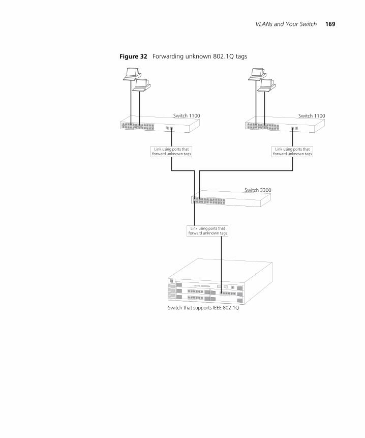
VLANs and Your Switch 169
Figure 32 Forwarding unknown 802.1Q tags

170 CHAPTER 6: VIRTUAL LANS (VLANS)
Connecting VLANs toOther VLANs
If the devices placed in a VLAN need to talk to devices in a different VLAN, each VLAN requires a connection to a routing or Layer 3 switching device. Communication between VLANs can only take place if they are all connected to a routing or Layer 3 switching device.
Connecting to VLANson Legacy Switch
Units
Your Switch supports VLANs using the IEEE 802.1Q VLAN standard, however legacy Switch units (for example, the SuperStack II Switch 1000) do not use this system. If you want to connect the VLANs on your Switch to the VLANs on legacy Switch units, note the following:
� You must define all the VLANs used by the legacy Switch units on your Switch; it only forwards traffic for legacy VLANs that are defined. When defining the VLANs, the Local ID on your Switch corresponds to the VLAN ID on the legacy Switch units.
� If your legacy Switch units use multiple VLANs, all connections between your Switch and the legacy Switch units must use VLT tagging. If your legacy Switch units use a single VLAN, the connections between your Switch and the legacy Switch units can be untagged.
� All ports on your Switch that are connected to legacy Switch units must have 802.1Q learning disabled.
� Do not define VLAN 15 on your Switch if the legacy Switch units use AutoSelect VLAN Mode.
� Do not define VLAN 16 on your Switch if the legacy Switch units use the Spanning Tree Protocol.
For examples of connecting VLANs on your Switch to VLANs on legacy Switch units, see “Connecting to a Legacy Network” on page 178.
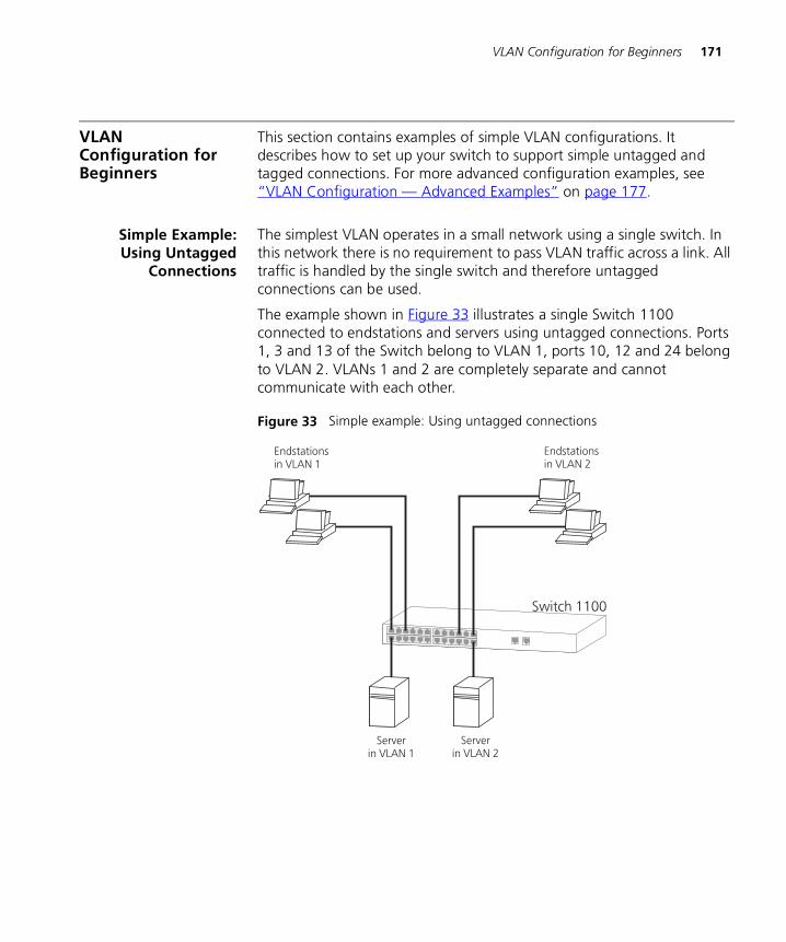
VLAN Configuration for Beginners 171
VLAN Configuration for Beginners
This section contains examples of simple VLAN configurations. It describes how to set up your switch to support simple untagged and tagged connections. For more advanced configuration examples, see “VLAN Configuration — Advanced Examples” on page 177.
Simple Example:Using Untagged
Connections
The simplest VLAN operates in a small network using a single switch. In this network there is no requirement to pass VLAN traffic across a link. All traffic is handled by the single switch and therefore untagged connections can be used.
The example shown in Figure 33 illustrates a single Switch 1100 connected to endstations and servers using untagged connections. Ports 1, 3 and 13 of the Switch belong to VLAN 1, ports 10, 12 and 24 belong to VLAN 2. VLANs 1 and 2 are completely separate and cannot communicate with each other.
Figure 33 Simple example: Using untagged connections
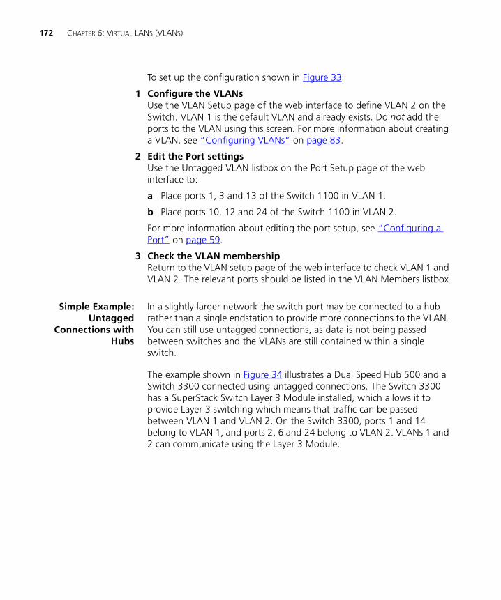
172 CHAPTER 6: VIRTUAL LANS (VLANS)
To set up the configuration shown in Figure 33:
1 Configure the VLANs Use the VLAN Setup page of the web interface to define VLAN 2 on the Switch. VLAN 1 is the default VLAN and already exists. Do not add the ports to the VLAN using this screen. For more information about creating a VLAN, see “Configuring VLANs” on page 83.
2 Edit the Port settingsUse the Untagged VLAN listbox on the Port Setup page of the web interface to:
a Place ports 1, 3 and 13 of the Switch 1100 in VLAN 1.
b Place ports 10, 12 and 24 of the Switch 1100 in VLAN 2.
For more information about editing the port setup, see “Configuring a Port” on page 59.
3 Check the VLAN membershipReturn to the VLAN setup page of the web interface to check VLAN 1 and VLAN 2. The relevant ports should be listed in the VLAN Members listbox.
Simple Example:Untagged
Connections withHubs
In a slightly larger network the switch port may be connected to a hub rather than a single endstation to provide more connections to the VLAN. You can still use untagged connections, as data is not being passed between switches and the VLANs are still contained within a single switch.
The example shown in Figure 34 illustrates a Dual Speed Hub 500 and a Switch 3300 connected using untagged connections. The Switch 3300 has a SuperStack Switch Layer 3 Module installed, which allows it to provide Layer 3 switching which means that traffic can be passed between VLAN 1 and VLAN 2. On the Switch 3300, ports 1 and 14 belong to VLAN 1, and ports 2, 6 and 24 belong to VLAN 2. VLANs 1 and 2 can communicate using the Layer 3 Module.
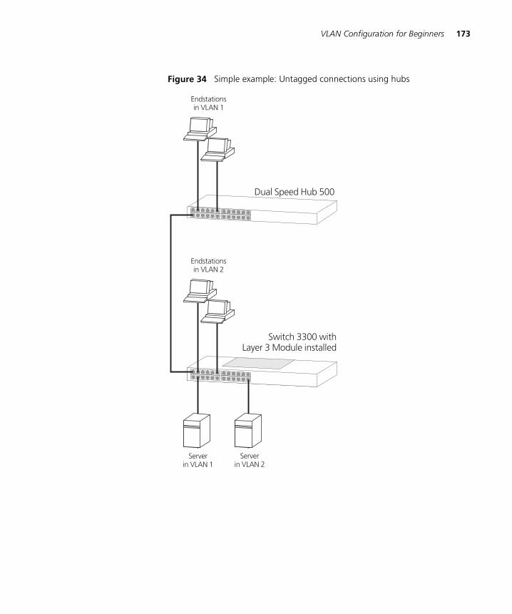
VLAN Configuration for Beginners 173
Figure 34 Simple example: Untagged connections using hubs
174 CHAPTER 6: VIRTUAL LANS (VLANS)
To set up the configuration shown in Figure 34:
1 Configure the VLANsUse the VLAN Setup page of the web interface to define VLAN 2 on the Switch 3300. VLAN 1 is the default VLAN and already exists. Do not add the ports to the VLAN using this screen. For more information about creating a VLAN, see “Configuring VLANs” on page 83
2 Edit the Port settingsUse the Untagged VLAN listbox on the Port Setup page of the web interface to:
a Place ports 1, and 14 in VLAN 1.
b Place ports 2, 6 and 24 in VLAN 2.
For more information about editing the port setup, see “Configuring a Port” on page 59.
3 Check the VLAN membershipReturn to the VLAN setup page of the web interface to check VLAN 1 and VLAN 2. The relevant ports should be listed in the VLAN Members listbox.
4 Connect VLAN 1 and VLAN 2Configure the Layer 3 Module to allow communication between VLANs 1 and 2. For more information, refer to the user documentation supplied with the Layer 3 Module.
5 Join the switch and hubConnect port 13 of the Dual Speed Hub 500 to port 1 of the Switch 3300.
Simple Example:802.1Q Tagged
Connections
In a network with more than one switch where the VLANs are distributed amongst different switches, you must use 802.1Q tagged connections so that all VLAN traffic can be passed along the link between the switches.
The example shown in Figure 35 illustrates two Switch 1100 units. Each switch has endstations in both VLAN 1 and VLAN 2 and each switch has a server for a VLAN. All endstations in VLAN 1 need to be able to connect to the server attached to Switch 1 and all endstations in VLAN 2 need to connect to the server attached to Switch 2.

VLAN Configuration for Beginners 175
Figure 35 Simple example: 802.1Q tagged connections
To set up the configuration shown in Figure 35:
1 Configure the VLANs on Switch 1Use the VLAN Setup page of the web interface to define VLAN 2. VLAN 1 is the default VLAN and already exists. Do not add the ports to the VLAN using this screen. For more information about creating a VLAN, see “Configuring VLANs” on page 83
2 Add untagged ports on Switch 1Use the Untagged VLAN listbox on the Port Setup page of the web interface to place untagged ports in the appropriate VLAN
For more information about editing the port setup, see “Configuring a Port” on page 59.
176 CHAPTER 6: VIRTUAL LANS (VLANS)
3 Add tagged port 26 on Switch 1Use the VLAN Setup page of the web interface to assign port 26 on Switch 1 to both VLANs 1 and 2 so that all VLAN traffic is passed over the link.
4 Configure the VLANs on Switch 2Use the VLAN Setup page of the web interface to define VLAN 2. VLAN 1 is the default VLAN and already exists. Do not add the ports to the VLAN using this screen. For more information about creating a VLAN, see “Configuring VLANs” on page 83
5 Add untagged ports on Switch 2Use the Untagged VLAN listbox on the Port Setup page of the web interface to place untagged ports in the appropriate VLAN
For more information about editing the port setup, see “Configuring a Port” on page 59.
6 Add tagged port 25 on Switch 2Use the VLAN Setup page of the web interface to assign port 25 on Switch 2 to both VLANs 1 and 2 so that all VLAN traffic is passed over the link.
7 Check the VLAN membership for both switchesReturn to the VLAN setup page of the web interface to check VLAN 1 and VLAN 2 for both switches. The relevant ports should be listed in the VLAN Members listbox.
8 Connect the switchesConnect port 26 on Switch 1 to port 25 on Switch 2.
The VLANs are now configured and operational and the endstations in both VLANs can communicate with their relevant servers.
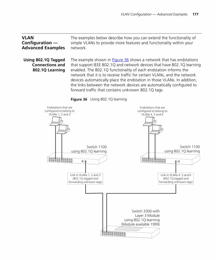
VLAN Configuration — Advanced Examples 177
VLAN Configuration — Advanced Examples
The examples below describe how you can extend the functionality of simple VLANs to provide more features and functionality within your network.
Using 802.1Q TaggedConnections and802.1Q Learning
The example shown in Figure 36 shows a network that has endstations that support IEEE 802.1Q and network devices that have 802.1Q learning enabled. The 802.1Q functionality of each endstation informs the network that it is to receive traffic for certain VLANs, and the network devices automatically place the endstation in those VLANs. In addition, the links between the network devices are automatically configured to forward traffic that contains unknown 802.1Q tags.
Figure 36 Using 802.1Q learning
178 CHAPTER 6: VIRTUAL LANS (VLANS)
To set up the configuration shown in Figure 36:
1 Configure the endstations attached to the left Switch 1100 so that they belong to VLANs 1, 2 and 3.
2 Configure the endstations attached to the right Switch 1100 so that they belong to VLANs 4, 5 and 6.
3 Enable 802.1Q learning on the left Switch 1100 using the 802.1Q VLAN Learning listbox on the Advanced Stack Setup page of the web interface.
4 Enable 802.1Q learning on the right Switch 1100 using the 802.1Q VLAN Learning listbox on the Advanced Stack Setup page of the web interface.
5 Enable 802.1Q learning on the Switch 3300 using the 802.1Q VLAN Learning listbox on the Advanced Stack Setup page of the web interface.
6 Configure the Layer 3 Module to allow communication between VLANs 1 to 6. For more information, refer to the user documentation supplied with the Layer 3 Module.
7 Connect port 26 of the left Switch 1100 to port 1 of the Switch 3300.
8 Connect port 25 of the right Switch 1100 to port 3 of the Switch 3300.
Connecting to aLegacy Network
The example shown in Figure 37 illustrates a Switch 1100 that has been connected to a legacy network using a VLT tagged link:
� The legacy network supports two VLANs (VLANs 1 and 2), and these can communicate using the connections (one per VLAN) between the Switch 3000 10/100 and the router.
� The endstations attached to the Switch 1100 use 802.1Q tagging and belong to VLANs 1 and 2. They can communicate directly with all the endstations attached to the Switch 1000 — they do not need the router because they belong to both VLANs.
To set up this configuration:
1 Configure the VLANs on the Switch 1100:
a Use the VLAN Setup page of the web interface to define VLANs 1 and 2. Note that the Local ID of the VLAN corresponds to the VLAN ID on the legacy network — therefore the Local ID of VLAN 1 must be 1, and the Local ID of VLAN 2 must be 2.
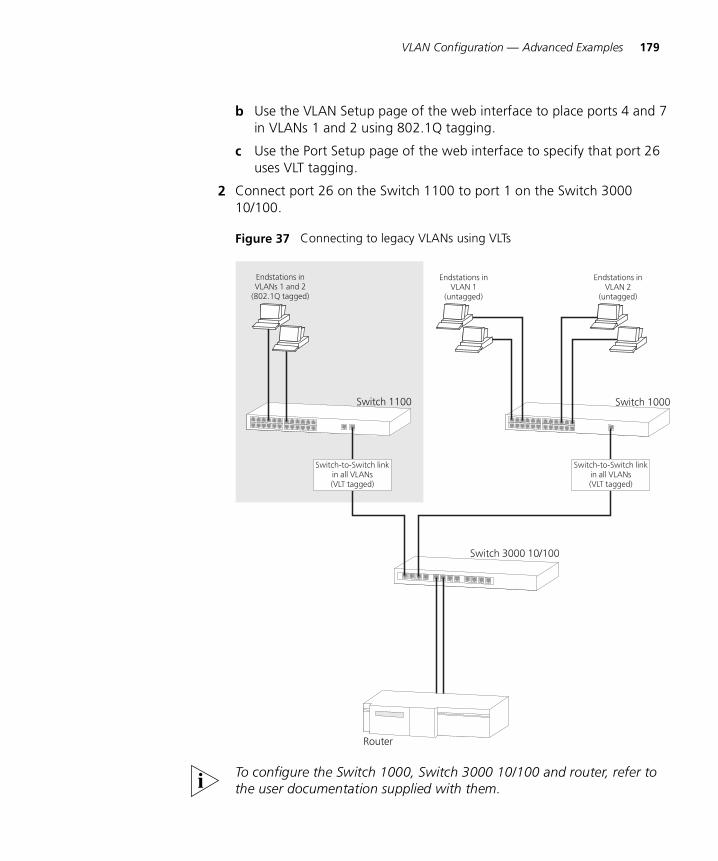
VLAN Configuration — Advanced Examples 179
b Use the VLAN Setup page of the web interface to place ports 4 and 7 in VLANs 1 and 2 using 802.1Q tagging.
c Use the Port Setup page of the web interface to specify that port 26 uses VLT tagging.
2 Connect port 26 on the Switch 1100 to port 1 on the Switch 3000 10/100.
Figure 37 Connecting to legacy VLANs using VLTs
To configure the Switch 1000, Switch 3000 10/100 and router, refer to the user documentation supplied with them.

180 CHAPTER 6: VIRTUAL LANS (VLANS)
7
FASTIPFastIP reduces the load on routing devices when VLANs are implemented on your network.
This chapter explains more about the concept of FastIP and how it is enabled on your Switch. It covers the following topics:
� What is FastIP?
� How FastIP Works
� An Example
� FastIP and the Switch Database
� Enabling FastIP

182 CHAPTER 7: FASTIP
What is FastIP? FastIP is a system that allows you to use the IEEE 802.1Q VLAN standard to reduce the load on routing devices when VLANs are implemented on your network.
Endstations within different VLANs can only communicate using a routing device; if there is a large amount of inter-VLAN traffic, the router can become overloaded and network performance can be affected. FastIP allows your endstations and Switch units to find secure short cuts for inter-VLAN traffic that bypass the routing device altogether.
When using FastIP, you must have a routing device (router or Layer 3 switch) in your network. In addition, we recommend that:
� All your Switch units have FastIP enabled. Note, however, that the FastIP system does work if:
� The Switch nearest to the routing device has FastIP enabled
� The rest of the Switch units use a shared Switch Database for all VLANs (the SuperStack II Switch 1000, Switch 3000 and Desktop Switch units use this system). For more information about shared Switch Databases, see “FastIP and the Switch Database” on page 186.
� All your endstations support FastIP. For more information, refer to the user documentation supplied with your endstations or the Network Interface Card (NIC) of your endstations.
How FastIP Works FastIP works as follows:
1 If an endstation A supports FastIP, it determines whether each data packet is being sent to a local endstation (one in the same VLAN) or a remote endstation (one in another VLAN).
2 If endstation A is about to send a data packet to a remote endstation B, it sends a special NHRP (Next Hop Resolution Protocol) packet to endstation B. This packet contains the MAC address and VLAN membership details of endstation A.
3 The NHRP packet passes through the Switch units to the routing device, and back through the Switch units to endstation B.
4 If endstation B supports FastIP, it records the MAC address and VLAN membership of endstation A.
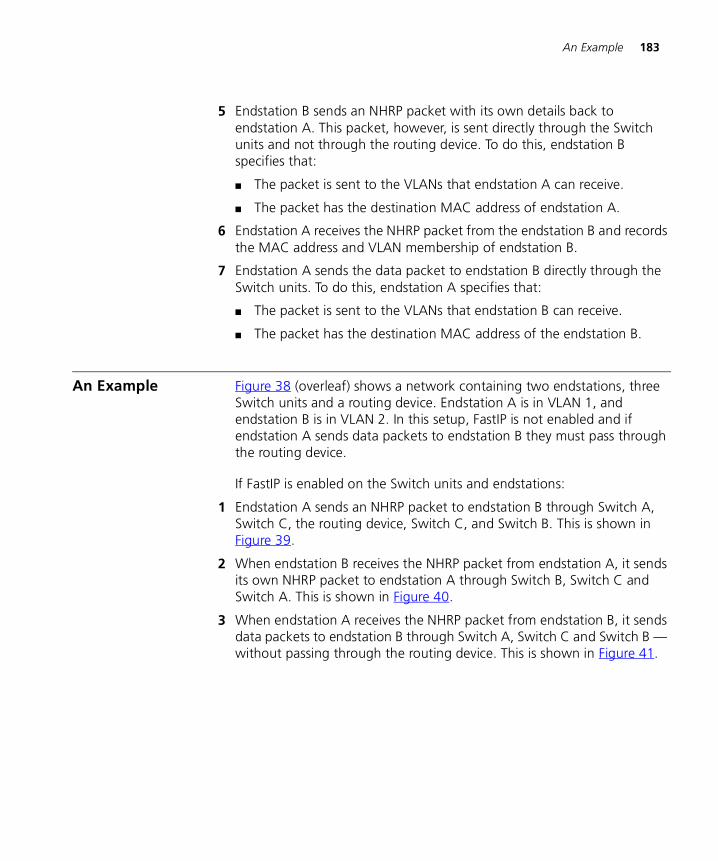
An Example 183
5 Endstation B sends an NHRP packet with its own details back to endstation A. This packet, however, is sent directly through the Switch units and not through the routing device. To do this, endstation B specifies that:
� The packet is sent to the VLANs that endstation A can receive.
� The packet has the destination MAC address of endstation A.
6 Endstation A receives the NHRP packet from the endstation B and records the MAC address and VLAN membership of endstation B.
7 Endstation A sends the data packet to endstation B directly through the Switch units. To do this, endstation A specifies that:
� The packet is sent to the VLANs that endstation B can receive.
� The packet has the destination MAC address of the endstation B.
An Example Figure 38 (overleaf) shows a network containing two endstations, three Switch units and a routing device. Endstation A is in VLAN 1, and endstation B is in VLAN 2. In this setup, FastIP is not enabled and if endstation A sends data packets to endstation B they must pass through the routing device.
If FastIP is enabled on the Switch units and endstations:
1 Endstation A sends an NHRP packet to endstation B through Switch A, Switch C, the routing device, Switch C, and Switch B. This is shown in Figure 39.
2 When endstation B receives the NHRP packet from endstation A, it sends its own NHRP packet to endstation A through Switch B, Switch C and Switch A. This is shown in Figure 40.
3 When endstation A receives the NHRP packet from endstation B, it sends data packets to endstation B through Switch A, Switch C and Switch B — without passing through the routing device. This is shown in Figure 41.
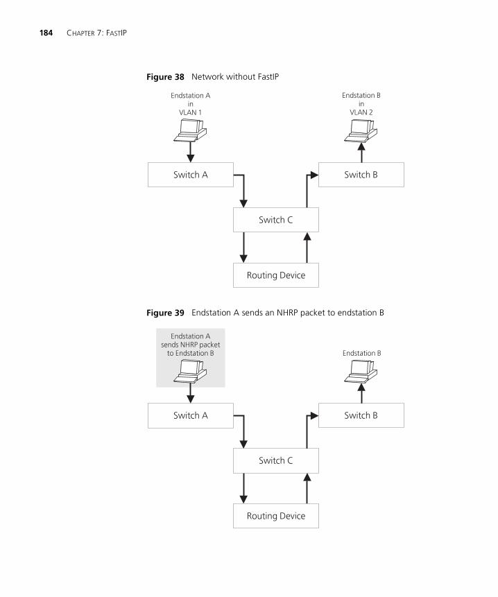
184 CHAPTER 7: FASTIP
Figure 38 Network without FastIP
Figure 39 Endstation A sends an NHRP packet to endstation B
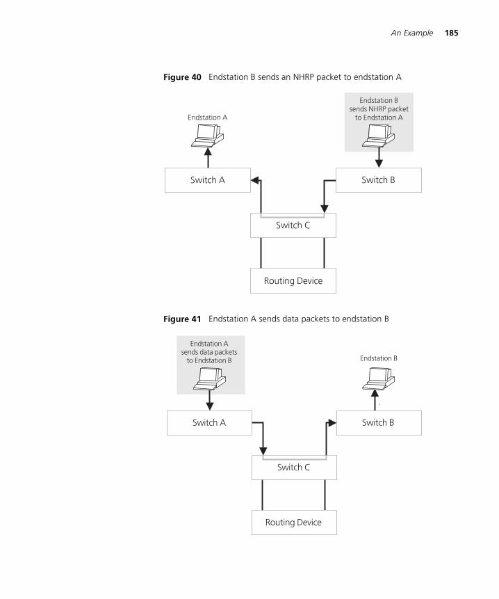
An Example 185
Figure 40 Endstation B sends an NHRP packet to endstation A
Figure 41 Endstation A sends data packets to endstation B
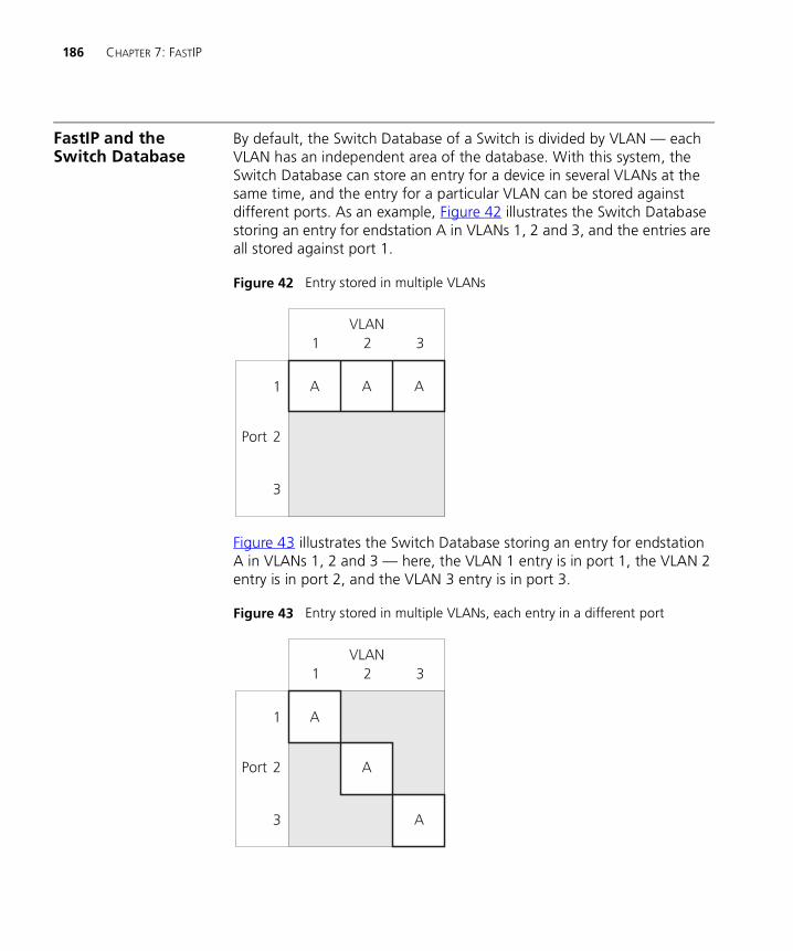
186 CHAPTER 7: FASTIP
FastIP and the Switch Database
By default, the Switch Database of a Switch is divided by VLAN — each VLAN has an independent area of the database. With this system, the Switch Database can store an entry for a device in several VLANs at the same time, and the entry for a particular VLAN can be stored against different ports. As an example, Figure 42 illustrates the Switch Database storing an entry for endstation A in VLANs 1, 2 and 3, and the entries are all stored against port 1.
Figure 42 Entry stored in multiple VLANs
Figure 43 illustrates the Switch Database storing an entry for endstation A in VLANs 1, 2 and 3 — here, the VLAN 1 entry is in port 1, the VLAN 2 entry is in port 2, and the VLAN 3 entry is in port 3.
Figure 43 Entry stored in multiple VLANs, each entry in a different port
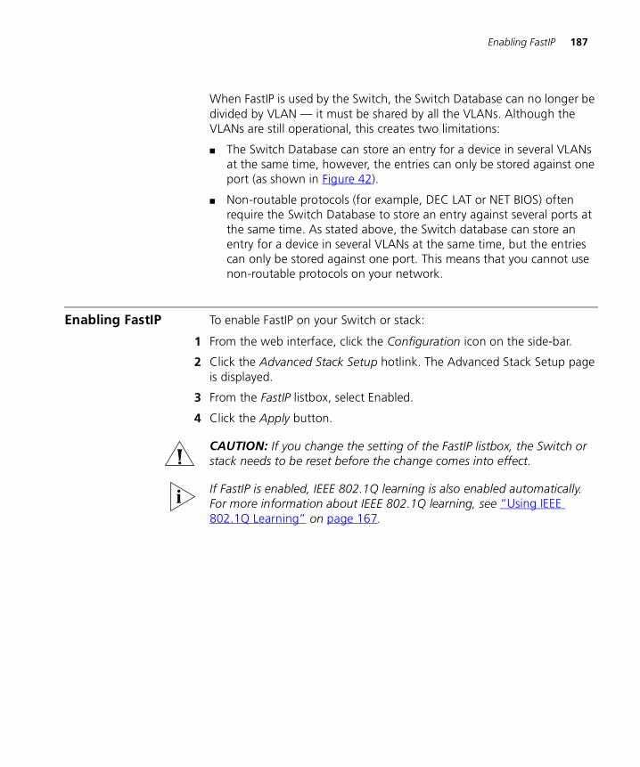
Enabling FastIP 187
When FastIP is used by the Switch, the Switch Database can no longer be divided by VLAN — it must be shared by all the VLANs. Although the VLANs are still operational, this creates two limitations:
� The Switch Database can store an entry for a device in several VLANs at the same time, however, the entries can only be stored against one port (as shown in Figure 42).
� Non-routable protocols (for example, DEC LAT or NET BIOS) often require the Switch Database to store an entry against several ports at the same time. As stated above, the Switch database can store an entry for a device in several VLANs at the same time, but the entries can only be stored against one port. This means that you cannot use non-routable protocols on your network.
Enabling FastIP To enable FastIP on your Switch or stack:
1 From the web interface, click the Configuration icon on the side-bar.
2 Click the Advanced Stack Setup hotlink. The Advanced Stack Setup page is displayed.
3 From the FastIP listbox, select Enabled.
4 Click the Apply button.
CAUTION: If you change the setting of the FastIP listbox, the Switch or stack needs to be reset before the change comes into effect.
If FastIP is enabled, IEEE 802.1Q learning is also enabled automatically. For more information about IEEE 802.1Q learning, see “Using IEEE 802.1Q Learning” on page 167.

188 CHAPTER 7: FASTIP
8
MULTICAST FILTERINGSetting up multicast filtering improves the performance of networks that carry multicast traffic.
This chapter explains multicasts, multicast filtering, and how multicast filtering can be implemented on your Switch. It covers the following topics:
� What is a Multicast?
� What is Multicast Filtering?
� Multicast Filtering and Your Switch
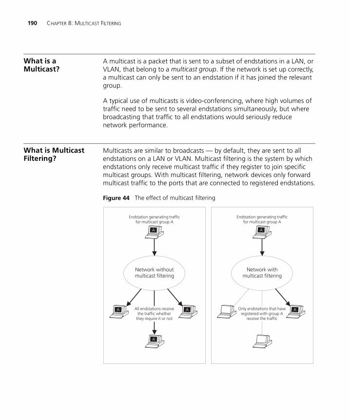
190 CHAPTER 8: MULTICAST FILTERING
What is a Multicast?
A multicast is a packet that is sent to a subset of endstations in a LAN, or VLAN, that belong to a multicast group. If the network is set up correctly, a multicast can only be sent to an endstation if it has joined the relevant group.
A typical use of multicasts is video-conferencing, where high volumes of traffic need to be sent to several endstations simultaneously, but where broadcasting that traffic to all endstations would seriously reduce network performance.
What is Multicast Filtering?
Multicasts are similar to broadcasts — by default, they are sent to all endstations on a LAN or VLAN. Multicast filtering is the system by which endstations only receive multicast traffic if they register to join specific multicast groups. With multicast filtering, network devices only forward multicast traffic to the ports that are connected to registered endstations.
Figure 44 The effect of multicast filtering
Multicast Filtering and Your Switch 191
Multicast Filtering and Your Switch
Your Switch provides automatic filtering support for two multicast systems:
� IEEE 802.1p, which uses the GARP Multicast Registration Protocol (GMRP)
� IGMP (Internet Group Management Protocol)
In addition, you can manually configure the filtering and forwarding of multicasts using Transcend® Network Management software.
IEEE 802.1p MulticastFiltering
The IEEE 802.1p standard defines a system that allows network devices to use a GARP Multicast Registration Protocol (GMRP) to register endstations with multicast groups. GMRP is protocol-independent, which means that it can be used on all LANs and VLANs that contain network devices and endstations which support IEEE 802.1p.
IEEE 802.1p multicast filtering works as follows:
1 If an 802.1p endstation wants to receive traffic for a multicast group, it sends out a join packet with a known multicast address to declare that it would like to join that group.
2 When the join packet arrives at a port on a Switch with 802.1p multicast learning enabled, the Switch specifies that the port is to forward traffic for the multicast group and then sends a similar packet to all other ports.
3 When traffic for the multicast group appears on the network, the Switch units only forward the traffic to ports that received a join packet.
Enabling 802.1p Multicast Learning
For information about enabling 802.1p multicast learning for an individual port on your Switch, see “Configuring a Port” on page 59. For information about enabling 802.1p multicast learning for a whole Switch or stack, see “Configuring the Advanced Stack Settings” on page 76.
For information about configuring IEEE 802.1p functionality on an endstation, refer to the user documentation supplied with your endstation or the endstation’s Network Interface Card (NIC).

192 CHAPTER 8: MULTICAST FILTERING
IGMP MulticastFiltering
IGMP is the system that all IP-supporting network devices use to register endstations with multicast groups. It can be used on all LANs and VLANs that contain an IP router and other network devices which support IP.
IGMP multicast filtering works as follows:
1 The IP router (or querier) periodically sends query packets to all the endstations in the LANs or VLANs that are connected to it.
If your network has more than one IP router, the one with the lowest IP address becomes the querier. If your network loses its IP router connections, the Switch unit with the lowest IP address becomes the querier — if this occurs, multicast filtering can only occur on the Default VLAN (VLAN 1).
2 When an IP endstation receives a query packet, it sends a report packet back that identifies the multicast group that the endstation would like to join.
3 When the report packet arrives at a port on a Switch with IGMP multicast learning enabled, the Switch specifies that the port is to forward traffic for the multicast group and then forwards the packet to the router.
4 When the router receives the report packet, it registers that the LAN or VLAN requires traffic for the multicast groups.
5 When the router forwards traffic for the multicast group to the LAN or VLAN, the Switch units only forward the traffic to ports that received a report packet.
Enabling IGMP Multicast Learning
For information about enabling IGMP multicast learning, see “Configuring the Advanced Stack Settings” on page 76.
For information about configuring IGMP functionality on an endstation, refer to the user documentation supplied with your endstation or the endstation’s Network Interface Card (NIC).
Manual Filtering You can manually configure your Switch to filter and forward multicasts using Transcend Enterprise Manager. This system can be used when endstations in your network do not support IEEE 802.1p or IGMP.

9
SPANNING TREE PROTOCOLUsing the Spanning Tree Protocol makes your network more resilient to link failure and also provides a protection from loops — one of the major causes of broadcast storms.
This chapter explains more about the protocol and the protocol features supported by your Switch. It covers the following topics:
� What is STP?
� How STP Works
� Using STP on a Network with Multiple VLANs
� Connecting to STP Systems on Legacy Switch Units
� Enabling STP
The protocol is a part of the 802.1D bridge specification defined by the IEEE Computer Society. To explain STP more effectively, your Switch will be defined as a bridge.

194 CHAPTER 9: SPANNING TREE PROTOCOL
What is STP? Using the Spanning Tree Protocol (STP) makes your network more resilient to link failure and also provides a protection from loops — one of the major causes of broadcast storms.
STP is a bridge-based system that allows you to implement parallel paths for network traffic and uses a loop-detection process to:
� Find and disable the less efficient paths (that is, the paths that have a lower bandwidth).
� Enable one of the less efficient paths if the most efficient path fails.
As an example, Figure 45 shows a network containing three LAN segments separated by three bridges. With this configuration, each segment can communicate with the others using two paths. Without STP, this configuration creates loops that cause the network to overload; however, STP allows you to have this configuration because it detects duplicate paths and prevents, or blocks, one of them from forwarding traffic.
Figure 46 shows the result of enabling STP on the bridges in the configuration. The STP system has decided that traffic from LAN segment 2 to LAN segment 1 can only flow through Bridges C and A.
If the link through Bridge C fails, as shown in Figure 47, the STP process reconfigures the network so that traffic from segment 2 flows through Bridge B.
Figure 45 A network configuration that creates loops
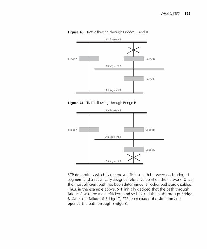
What is STP? 195
Figure 46 Traffic flowing through Bridges C and A
Figure 47 Traffic flowing through Bridge B
STP determines which is the most efficient path between each bridged segment and a specifically assigned reference point on the network. Once the most efficient path has been determined, all other paths are disabled. Thus, in the example above, STP initially decided that the path through Bridge C was the most efficient, and so blocked the path through Bridge B. After the failure of Bridge C, STP re-evaluated the situation and opened the path through Bridge B.
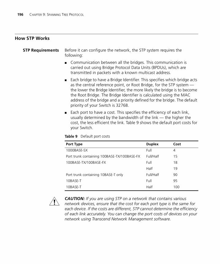
196 CHAPTER 9: SPANNING TREE PROTOCOL
How STP Works
STP Requirements Before it can configure the network, the STP system requires the following:
� Communication between all the bridges. This communication is carried out using Bridge Protocol Data Units (BPDUs), which are transmitted in packets with a known multicast address.
� Each bridge to have a Bridge Identifier. This specifies which bridge acts as the central reference point, or Root Bridge, for the STP system — the lower the Bridge Identifier, the more likely the bridge is to become the Root Bridge. The Bridge Identifier is calculated using the MAC address of the bridge and a priority defined for the bridge. The default priority of your Switch is 32768.
� Each port to have a cost. This specifies the efficiency of each link, usually determined by the bandwidth of the link — the higher the cost, the less efficient the link. Table 9 shows the default port costs for your Switch.
CAUTION: If you are using STP on a network that contains various network devices, ensure that the cost for each port type is the same for each device. If the costs are different, STP cannot determine the efficiency of each link accurately. You can change the port costs of devices on your network using Transcend Network Management software.
Table 9 Default port costs
Port Type Duplex Cost
1000BASE-SX Full 4
Port trunk containing 100BASE-TX/100BASE-FX Full/Half 15
100BASE-TX/100BASE-FX Full
Half
18
19
Port trunk containing 10BASE-T only Full/Half 90
10BASE-T Full 95
10BASE-T Half 100
How STP Works 197
STP Calculation The first stage in the STP process is the calculation stage. During this stage, each bridge on the network transmits BPDUs that allow the system to work out:
� The identity of the bridge that is to be the Root Bridge — the central reference point from which the network is configured.
� The Root Path Costs for each bridge — that is, the cost of the paths from each bridge to the Root Bridge.
� The identity of the port on each bridge that is to be the Root Port — the one that is connected to the Root Bridge using the most efficient path, that is, the one that has the lowest Root Path Cost. Note that the Root Bridge does not have a Root Port.
� The identity of the bridge that is to be the Designated Bridge of each LAN segment — the one that has the lowest Root Path Cost from that segment. Note that if several bridges have the same Root Path Cost, the one with the lowest Bridge Identifier becomes the Designated Bridge.
All traffic destined to pass in the direction of the Root Bridge flows through the Designated Bridge. The port on this bridge that connects to the segment is called the Designated Bridge Port.
STP Configuration After all the bridges on the network have agreed on the identity of the Root Bridge, and have established the other relevant parameters, each bridge is configured to forward traffic only between its Root Port and the Designated Bridge Ports for the respective network segments. All other ports are blocked, which means that they are prevented from receiving or forwarding traffic.
STP Reconfiguration Once the network topology is stable, all the bridges listen for special Hello BPDUs transmitted from the Root Bridge at regular intervals. If a bridge does not receive a Hello BPDU after a certain interval (the Max Age time), the bridge assumes that the Root Bridge, or a link between itself and the Root Bridge, has gone down. The bridge then reconfigures the network to cater for the change. If the topology of your network changes, the first bridge to detect the change sends out an SNMP trap.
CAUTION: To ensure that the bridges can communicate after a reconfiguration, all potential Designated Bridge ports and Root Ports must belong to the same VLANs. For more information about VLANs, see “Virtual LANs (VLANs)” on page 163.
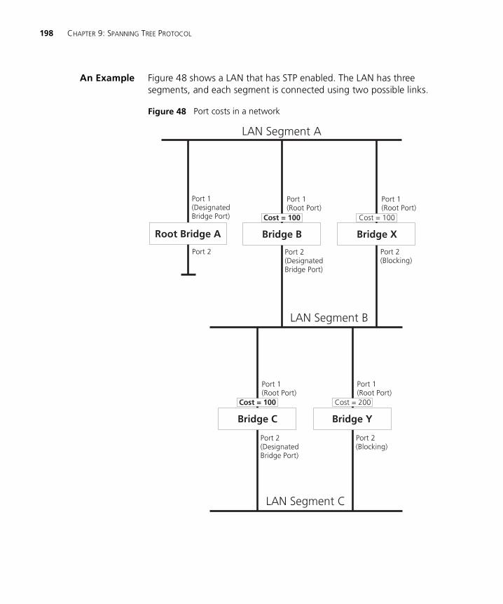
198 CHAPTER 9: SPANNING TREE PROTOCOL
An Example Figure 48 shows a LAN that has STP enabled. The LAN has three segments, and each segment is connected using two possible links.
Figure 48 Port costs in a network
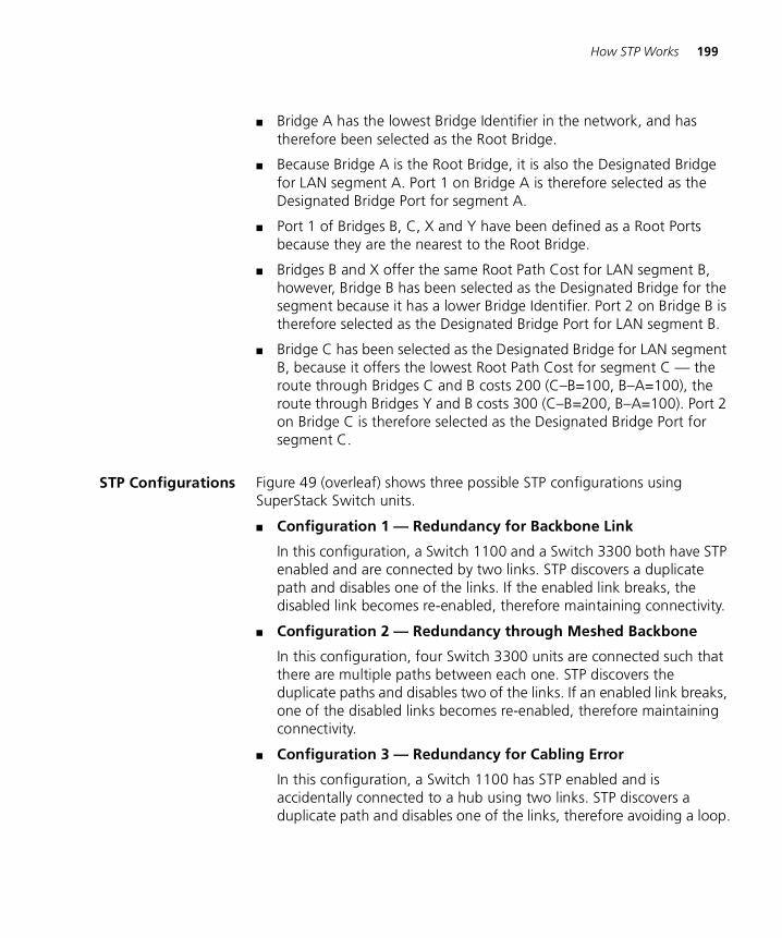
How STP Works 199
� Bridge A has the lowest Bridge Identifier in the network, and has therefore been selected as the Root Bridge.
� Because Bridge A is the Root Bridge, it is also the Designated Bridge for LAN segment A. Port 1 on Bridge A is therefore selected as the Designated Bridge Port for segment A.
� Port 1 of Bridges B, C, X and Y have been defined as a Root Ports because they are the nearest to the Root Bridge.
� Bridges B and X offer the same Root Path Cost for LAN segment B, however, Bridge B has been selected as the Designated Bridge for the segment because it has a lower Bridge Identifier. Port 2 on Bridge B is therefore selected as the Designated Bridge Port for LAN segment B.
� Bridge C has been selected as the Designated Bridge for LAN segment B, because it offers the lowest Root Path Cost for segment C — the route through Bridges C and B costs 200 (C–B=100, B–A=100), the route through Bridges Y and B costs 300 (C–B=200, B–A=100). Port 2 on Bridge C is therefore selected as the Designated Bridge Port for segment C.
STP Configurations Figure 49 (overleaf) shows three possible STP configurations using SuperStack Switch units.
� Configuration 1 — Redundancy for Backbone Link
In this configuration, a Switch 1100 and a Switch 3300 both have STP enabled and are connected by two links. STP discovers a duplicate path and disables one of the links. If the enabled link breaks, the disabled link becomes re-enabled, therefore maintaining connectivity.
� Configuration 2 — Redundancy through Meshed Backbone
In this configuration, four Switch 3300 units are connected such that there are multiple paths between each one. STP discovers the duplicate paths and disables two of the links. If an enabled link breaks, one of the disabled links becomes re-enabled, therefore maintaining connectivity.
� Configuration 3 — Redundancy for Cabling Error
In this configuration, a Switch 1100 has STP enabled and is accidentally connected to a hub using two links. STP discovers a duplicate path and disables one of the links, therefore avoiding a loop.
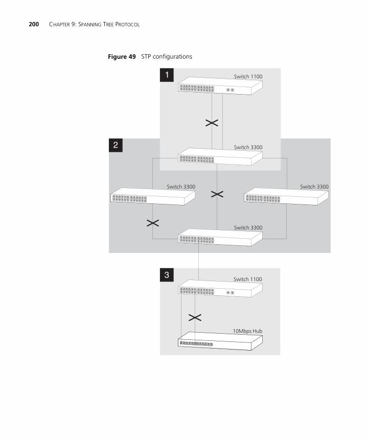
200 CHAPTER 9: SPANNING TREE PROTOCOL
Figure 49 STP configurations
Using STP on a Network with Multiple VLANs 201
Using STP on a Network with Multiple VLANs
Your Switch does not take into account VLANs when it calculates STP information — the calculations are only performed on the basis of duplicate connections. For this reason, some network configurations can result in VLANs being subdivided into a number of isolated sections by the STP system.
For example, Figure 50 shows a network containing VLANs 1 and 2. They are connected using the 802.1Q-tagged link between Switch B and Switch C. By default, this link has a path cost of 100 and is automatically blocked because the other Switch-to-Switch connections have a path cost of 36 (18+18). This means that both VLANs are now subdivided — VLAN 1 on Switch units A and B cannot communicate with VLAN 1 on Switch C, and VLAN 2 on Switch units A and C cannot communicate with VLAN 2 on Switch B.
Figure 50 A configuration that separates VLANs
To avoid any VLAN subdivision, 3Com recommend that all inter-Switch connections are made members of all available 802.1Q VLANs to ensure connectivity at all times. For example, the connections between Switches A and B, and Switches A and C should be 802.1Q tagged and carrying VLANs 1 and 2 to ensure connectivity.
For more information about VLAN Tagging, see Chapter 6, Virtual LANs (VLANs).
202 CHAPTER 9: SPANNING TREE PROTOCOL
Connecting to STP Systems on Legacy Switch Units
If you are connecting your Switch to legacy units that support STP, note the following:
� Your Switch supports one STP system; however legacy Switch units (for example, the SuperStack II Switch 1000) may support one STP system per VLAN. Consequently:
� If the legacy Switch units use a single VLAN and you connect your Switch to them using an untagged link, the STP system of your Switch and the STP system of the legacy Switch units are combined.
� If the legacy Switch units use multiple VLANs and you connect your Switch to them using a VLT tagged link, the STP system of your Switch and the STP system of the legacy Switch units are completely separate. This means that if you connect your Switch to a legacy Switch unit using multiple VLT links, a loop may created.
� Some legacy units cannot use VLAN 16 if they are using STP. If your Switch is connected to one of these units, VLAN 16 traffic is blocked on the port.
Enabling STP To enable STP on your Switch via the command line interface, see “Enabling and Disabling Spanning Tree on a Bridge” on page 116.
To enable STP on your Switch via the web management interface:
1 From the web interface, click the Configuration icon on the side-bar.
2 Click the Advanced Stack Setup hotlink. The Advanced Stack Setup page is displayed.
3 From the Spanning Tree listbox, select Enabled.
4 Click the Apply button.
You cannot enable STP if you have set up any resilient links on the Switch.
10
RMONUsing the RMON (Remote Monitoring) capabilities of a Switch allows network administrators to improve their efficiency and reduce the load on their network.
This chapter explains more about the RMON concept and the RMON features supported by the Switch. It covers the following topics:
� What is RMON?
� Benefits of RMON
� RMON and Your Switch
You can only use the RMON features of the Switch if you have an RMON management application, such as the RMON application supplied with 3Com Transcend® Enterprise Manager software.
204 CHAPTER 10: RMON
What is RMON? RMON is the common abbreviation for Remote Monitoring, a system defined by the IETF that allows you to monitor the traffic of LANs or VLANs remotely.
A typical RMON setup consists of two components:
� The RMON probe — An intelligent, remotely-controlled device or software agent that continually collects statistics about a LAN segment or VLAN, and transfers the information to a management workstation on request or when a pre-defined threshold is crossed.
� The management workstation — Communicates with the RMON probe and collects the statistics from it. The workstation does not have to be on the same network as the probe and can manage the probe by in-band or out-of-band connections.
The RMON Groups The IETF define nine groups of Ethernet RMON statistics. This section describes these groups, and details how they can be used.
Statistics
The Statistics group provides traffic and error statistics showing packets, bytes, broadcasts, multicasts and errors on a LAN segment or VLAN.
Information from the Statistics group is used to detect changes in traffic and error patterns in critical areas of your network.
History
The History group provides historical views of network performance by taking periodic samples of the counters supplied by the Statistics group.
The group is useful for analyzing the traffic patterns and trends on a LAN segment or VLAN, and for establishing the normal operating parameters of your network.
Alarms
The Alarms group provides a mechanism for setting thresholds and sampling intervals to generate events on any RMON variable.
Alarms are used to inform you of network performance problems and they can trigger automated responses through the Events group.
What is RMON? 205
Hosts
The Hosts group specifies a table of traffic and error statistics for each host (endstation) on a LAN segment or VLAN. Statistics include packets sent and received, octets sent and received, as well as broadcasts, multicasts, and error packets sent.
The group supplies a list of all hosts that have transmitted across the network. The next group, Hosts Top N, requires implementation of the Hosts group.
Hosts Top N
The Hosts Top N group extends the Hosts table by providing sorted host statistics, such as the top 20 hosts sending packets or an ordered list of all hosts according to the errors they sent over the last 24 hours.
Matrix
The Matrix group shows the amount of traffic and number of errors between pairs of devices on a LAN segment or VLAN. For each pair, the Matrix group maintains counters of the number of packets, number of octets, and error packets between the hosts.
The conversation matrix helps you to examine network statistics in more detail to discover, for example, who is talking to whom or if a particular PC is producing more errors when communicating with its file server. Combined with Hosts Top N, this allows you to view the busiest hosts and their primary conversation partners.
Events
The Events group provides you with the ability to create entries in an event log and send SNMP traps to the management workstation. Events can originate from a crossed threshold on any RMON variable. In addition to the standard five traps required by SNMP (link up, link down, warm start, cold start, and authentication failure), RMON adds two more: rising threshold and falling threshold.
Effective use of the Events group saves you time; rather than having to watch real-time graphs for important occurrences, you can depend on the Event group for notification. Through the SNMP traps, events can trigger other actions, therefore providing a way to automatically respond to certain occurrences.
206 CHAPTER 10: RMON
Benefits of RMON Using the RMON features of your Switch has three main advantages:
� It improves your efficiency
Using RMON probes allows you to remain at one workstation and collect information from widely dispersed LAN segments or VLANs. This means that the time taken to reach a problem site, set up equipment, and begin collecting information is largely eliminated.
� It allows you to manage your network in a more proactive manner
If they are configured correctly, RMON probes deliver information before problems occur. This means that you can take action before they affect users. In addition, probes record the behavior of your network, so that you can analyze the causes of problems.
� It reduces the load on the network and the management workstation
Traditional network management involves a management workstation polling network devices at regular intervals to gather statistics and identify problems or trends. As network sizes and traffic levels grow, this approach places a strain on the management workstation and also generates large amounts of traffic.
An RMON probe, however, autonomously looks at the network on behalf of the management workstation without affecting the characteristics and performance of the network. The probe reports by exception, which means that it only informs the management workstation when the network has entered an abnormal state.
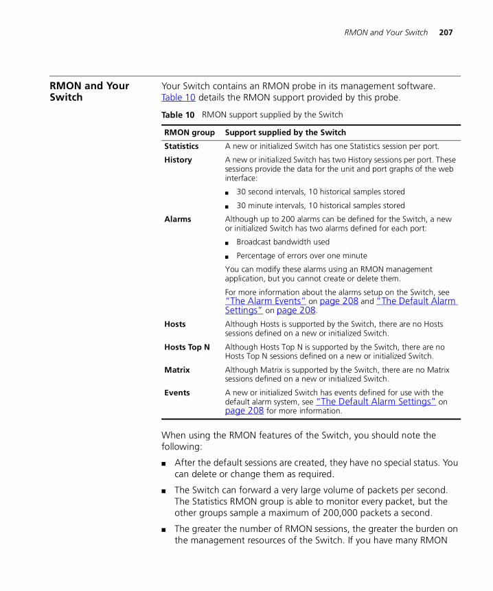
RMON and Your Switch 207
RMON and Your Switch
Your Switch contains an RMON probe in its management software. Table 10 details the RMON support provided by this probe.
When using the RMON features of the Switch, you should note the following:
� After the default sessions are created, they have no special status. You can delete or change them as required.
� The Switch can forward a very large volume of packets per second. The Statistics RMON group is able to monitor every packet, but the other groups sample a maximum of 200,000 packets a second.
� The greater the number of RMON sessions, the greater the burden on the management resources of the Switch. If you have many RMON
Table 10 RMON support supplied by the Switch
RMON group Support supplied by the Switch
Statistics A new or initialized Switch has one Statistics session per port.
History A new or initialized Switch has two History sessions per port. These sessions provide the data for the unit and port graphs of the web interface:
� 30 second intervals, 10 historical samples stored
� 30 minute intervals, 10 historical samples stored
Alarms Although up to 200 alarms can be defined for the Switch, a new or initialized Switch has two alarms defined for each port:
� Broadcast bandwidth used
� Percentage of errors over one minute
You can modify these alarms using an RMON management application, but you cannot create or delete them.
For more information about the alarms setup on the Switch, see “The Alarm Events” on page 208 and “The Default Alarm Settings” on page 208.
Hosts Although Hosts is supported by the Switch, there are no Hosts sessions defined on a new or initialized Switch.
Hosts Top N Although Hosts Top N is supported by the Switch, there are no Hosts Top N sessions defined on a new or initialized Switch.
Matrix Although Matrix is supported by the Switch, there are no Matrix sessions defined on a new or initialized Switch.
Events A new or initialized Switch has events defined for use with the default alarm system, see “The Default Alarm Settings” on page 208 for more information.
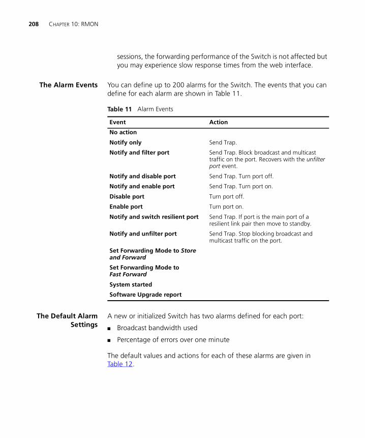
208 CHAPTER 10: RMON
sessions, the forwarding performance of the Switch is not affected but you may experience slow response times from the web interface.
The Alarm Events You can define up to 200 alarms for the Switch. The events that you can define for each alarm are shown in Table 11.
The Default AlarmSettings
A new or initialized Switch has two alarms defined for each port:
� Broadcast bandwidth used
� Percentage of errors over one minute
The default values and actions for each of these alarms are given in Table 12.
Table 11 Alarm Events
Event Action
No action
Notify only Send Trap.
Notify and filter port Send Trap. Block broadcast and multicast traffic on the port. Recovers with the unfilter port event.
Notify and disable port Send Trap. Turn port off.
Notify and enable port Send Trap. Turn port on.
Disable port Turn port off.
Enable port Turn port on.
Notify and switch resilient port Send Trap. If port is the main port of a resilient link pair then move to standby.
Notify and unfilter port Send Trap. Stop blocking broadcast and multicast traffic on the port.
Set Forwarding Mode to Store and Forward
Set Forwarding Mode toFast Forward
System started
Software Upgrade report
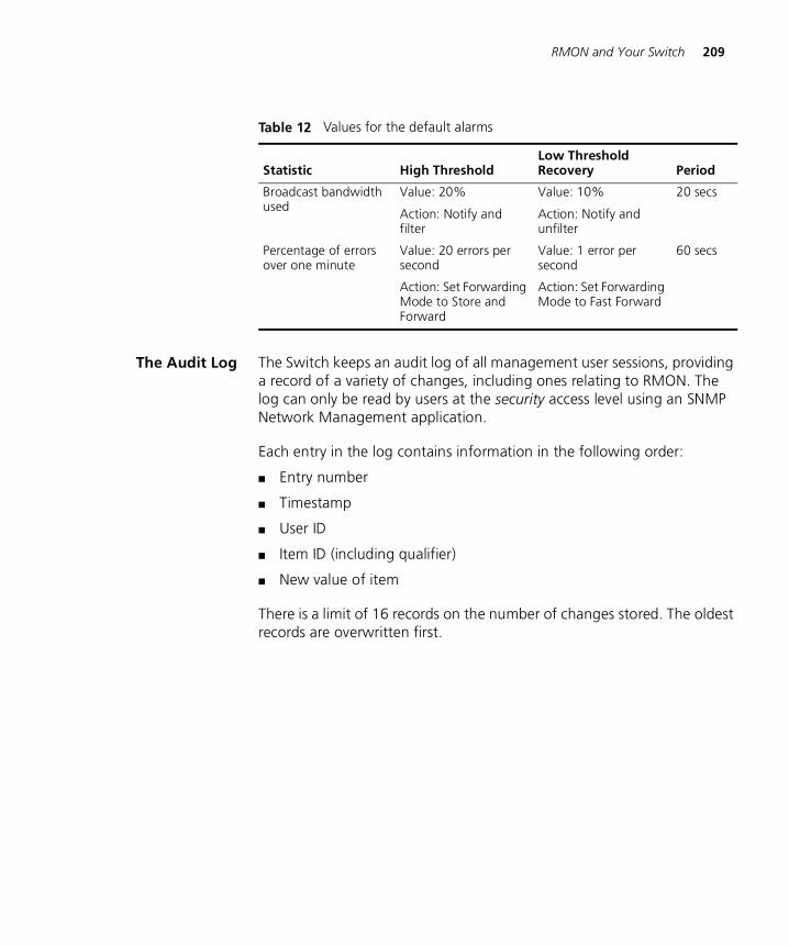
RMON and Your Switch 209
The Audit Log The Switch keeps an audit log of all management user sessions, providing a record of a variety of changes, including ones relating to RMON. The log can only be read by users at the security access level using an SNMP Network Management application.
Each entry in the log contains information in the following order:
� Entry number
� Timestamp
� User ID
� Item ID (including qualifier)
� New value of item
There is a limit of 16 records on the number of changes stored. The oldest records are overwritten first.
Table 12 Values for the default alarms
Statistic High ThresholdLow Threshold Recovery Period
Broadcast bandwidth used
Value: 20%
Action: Notify and filter
Value: 10%
Action: Notify and unfilter
20 secs
Percentage of errors over one minute
Value: 20 errors per second
Action: Set Forwarding Mode to Store and Forward
Value: 1 error per second
Action: Set Forwarding Mode to Fast Forward
60 secs

210 CHAPTER 10: RMON

IV
PROBLEM SOLVINGChapter 11 Problem Solving

11
PROBLEM SOLVINGThis chapter contains a list of known problems and suggested solutions. It covers the following topics:
� Solving Web Interface Problems
� Solving Command Line Interface Problems
� Solving SNMP Management Software Problems
� Solving Serial Web Utility Problems
� Solving Management Software Upgrade Utility Problems
� Solving Other Problems
If you have a problem that is not listed here and you cannot solve it, please contact your local technical support representative.

214 CHAPTER 11: PROBLEM SOLVING
Solving Web Interface Problems
The Web browser cannot access the Switch over the network. Check that:
� The IP information for the Switch is correctly configured. See “Setting Up IP Information” on page 58 or “Specifying IP and SLIP Information” on page 134 for more information.
� If you are managing the Switch over the network, remote access to the management software of the Switch is enabled. For more information, see “Enabling and Disabling Remote Access” on page 151.
The Web browser cannot access the Switch over a serial link from a management station running Windows® 95. You must access the Switch using the 3Com Serial Web Utility (SLIP Driver); see “Serial Web Utility” on page 227.
The Web browser can no longer access the Switch over the network. Check that:
� Remote access to the management software of the Switch has not been disabled. For more information, see “Enabling and Disabling Remote Access” on page 151.
� The port through which you are trying to access the Switch has not been disabled. For more information, see “Displaying the Status of the Ports” on page 54, or if it is enabled, check the connections and network cabling for the port.
� The port through which you are trying to manage the Switch has not been moved from the Default VLAN (VLAN 1). This is the only VLAN that can be used to access the management software of the Switch.
If there is still a problem, try accessing the Switch through a different port. If you can now access the Switch, a problem may have occurred with the original port. Contact your supplier for further advice.
Some of the web interface is not displayed in the Web browser after downloading. This is probably due to large amounts of traffic on the network. Either reload the web interface page, or click in the part of the interface that has not displayed and select the reload frame option in your Web browser.
Solving Web Interface Problems 215
The web interface takes time to respond to commands, and "Document contains no data" messages are displayed. Too many users are accessing the web interface at the same time. We recommend that you allow only three users to access the interface.
"URL not found" messages are displayed when the Help or Documentation icons are clicked. The web interface cannot access the online help or online documentation files. For more information, see “Installing Online Help and Documentation” on page 34.
"URL not found" messages are displayed when the 3Com Library, 3Com Contacts or 3Com Support icons are clicked. Your management workstation cannot access the World Wide Web. Contact your network administrator.
The units in the Unit icon are not displayed in the order that they are stacked. If you have a stack of two units connected back-to-back, the unit with the lowest MAC address is displayed at the bottom of the Unit icon. If you have a stack of up to four units connected using a Matrix Module, the order of units in the Unit icon follows the ports on the Matrix Module — the unit connected to the Unit 1 port is displayed at the bottom of the Unit icon, the unit connected to the Unit 2 port is displayed above that unit, and so on.
The Switch graphic shown on the web interface does not refresh automatically. You may need to make a small change to your Web browser so that it always downloads the latest version of a web page from the web interface. To do this for Netscape Navigator Version 3.0:
1 Start Netscape Navigator.
2 From the Options menu, select Network Preferences.
3 The Preferences dialog box appears.
4 Check the Every Time checkbox.
5 Click OK.
216 CHAPTER 11: PROBLEM SOLVING
To do this for Microsoft Internet Explorer Version 3.0:
1 Start Microsoft Internet Explorer.
2 From the View menu, select Options.
3 The Options dialog box appears.
4 Select the Advanced tab, and in the Advanced property sheet click Settings.
5 Check the Every visit to the page checkbox.
6 Click OK.
You forget your password while logged out of the web interface and cannot log in. Ask another user with Security access level to log in and initialize the Switch. This returns the Switch to its default (factory) settings, including any password information. For more information, see “Initializing All the Units in the Stack” on page 88.
In the case where no-one knows a password for a user with Security access level, the Switch needs to be sent back to your supplier so that it can be returned to 3Com.
A management software upgrade has failed, and you can no longer manage the Switch using the web interface. Try accessing the command line interface and upgrading the Switch again. If that is not possible, use the Management Software Upgrade Utility to upgrade it through the console port. For more information about the Management Software Upgrade Utility, see “Using the Upgrade Utility” on page 231.
If the Switch is stacked, separate each Switch from the stack and use the Management Software Upgrade Utility to upgrade each Switch individually.
Solving Command Line Interface Problems
The terminal or terminal emulator cannot access the Switch. Check that:
� Your terminal or terminal emulator is correctly configured to operate as a generic (TTY) terminal, or a VT100 terminal.
� You have performed the command line interface wake-up procedure by pressing [Return] a few times.
Solving Command Line Interface Problems 217
� The settings on your terminal or terminal emulator are correct:
� 8 data bits
� no parity
� 1 stop bit
The auto-configuration feature of the Switch only works with line speeds from 1200 to 19,200 baud.
� If you are managing the Switch over the network:
� Remote access to the management software of the Switch is enabled. For more information, see “Enabling and Disabling Remote Access” on page 151.
� The port through which you are trying to manage the Switch belongs to the Default VLAN (VLAN 1). This is the only VLAN that can be used to access the management software of the Switch.
If the login sequence still does not display, reset the Switch. For more information, see “Resetting All the Units in the Stack” on page 88 or page 151. If this does not work, initialize the Switch. For more information, see “Initializing All the Units in the Stack” on page 88 or page 151.
The terminal or terminal emulator can no longer access the Switch over the network. Check that:
� Remote access to the management software of the Switch has not been disabled. For more information, see “Enabling and Disabling Remote Access” on page 151.
� The port through which you are trying to access the Switch has not been disabled. For more information, see “Displaying the Status of the Ports” on page 54, or if it is enabled, check the connections and network cabling for the port.
� The port through which you are trying to manage the Switch has not been moved from the Default VLAN (VLAN 1). This is the only VLAN that can be used to access the management software of the Switch.
If there is still a problem, try accessing the stack through a different port. If you can now access the Switch, a problem may have occurred with the original port. Contact your supplier for further advice.
218 CHAPTER 11: PROBLEM SOLVING
You forget your password and cannot log in. Ask another user with Security access level to log in and initialize the Switch. This returns the Switch to its default (factory) settings, including any password information. For more information, see “Initializing All the Units in the Stack” on page 151.
In the case where no-one knows a password for a user with Security access level, the Switch needs to be sent back to your supplier so that it can be returned to 3Com.
A management software upgrade has failed, and you can no longer manage the Switch using the command line interface. Try accessing the command line interface and upgrading the Switch again. If that is not possible, use the Management Software Upgrade Utility to upgrade it through the console port. For more information about the Management Software Upgrade Utility, see “Using the Upgrade Utility” on page 231.
If the Switch is stacked, separate each Switch from the stack and use the Management Software Upgrade Utility to upgrade each Switch individually.
Solving SNMP Management Software Problems
The SNMP Network Management Software cannot access the Switch. Check that:
� The IP information for the Switch is correctly configured. See “Setting Up IP Information” on page 58 or “Specifying IP and SLIP Information” on page 134 for more information.
� The Switch was reset after the IP information was defined.
� The IP information for the Switch is correctly recorded by the Network Management software. For more information, see the documentation supplied with your Network Management software.
� The community strings defined for the Switch are the same as the ones defined in the Network Management software. See “Specifying SNMP Community Strings” on page 137 for more information.
� Remote access to the management software of the Switch is enabled. For more information, see “Enabling and Disabling Remote Access” on page 151.
Solving Serial Web Utility Problems 219
� The port through which you are trying to manage the Switch belongs to the Default VLAN (VLAN 1). This is the only VLAN that can be used to access the management software of the Switch.
Traps are not received by the SNMP Network Management software. Check that the IP information of the SNMP Network Management software is correctly recorded by the Switch.
The SNMP Network Management software can no longer access the Switch. Check that:
� Remote access to the management software of the Switch has not been disabled. For more information, see “Enabling and Disabling Remote Access” on page 151.
� The port through which you are trying to access the Switch has not been disabled. For more information, see “Displaying the Status of the Ports” on page 54, or if it is enabled, check the connections and network cabling for the port.
� The port through which you are trying to manage the Switch has not been moved from the Default VLAN (VLAN 1). This is the only VLAN that can be used to access the management software of the Switch.
If there is still a problem, try accessing the Switch through a different port. If you can now access the Switch, a problem may have occurred with the original port. Contact your supplier for further advice.
Solving Serial Web Utility Problems
You cannot connect to the web interface of the Switch.
Check that:
� The Switch is powered-up.
� You are using a proper null modem cable. Pin-outs are detailed in the User Guide of your Switch.
� The flow control and line speed (baud rate) settings are the same on the Switch and on the management workstation:
� You have not changed the line speed setting of the management workstation after the Switch has connected (the Switch only configures its line speed the first time it connects).
� You have selected the correct serial port on your management workstation.
220 CHAPTER 11: PROBLEM SOLVING
You can change some of the settings for the management workstation using the Advanced Configuration Parameters dialog box. To display this, select the Serial Web Setup program item in the Serial Web program group.
Solving Management Software Upgrade Utility Problems
An error occurs when the utility attempts to connect through the serial port of the PC. The serial port being used is not the same as the serial port specified in the upgrade command. Retry the command ensuring that you specify a value of ‘1’ or ‘2’ for the serial port.
An error occurs when the utility attempts to communicate with the Switch. There could be a number of reasons for this:
� The Switch is not being powered-up within 5 seconds of pressing [Return].
� The null modem cable is not connected to the console port of the Switch.
� The null modem cable is not connected to the serial port of the PC, or, the serial port being used is not the same as the serial port specified in the upgrade command.
� The Switch is not being powered-down and up as directed.
Retry the command ensuring that you follow all the steps.
An error occurs when the utility attempts to open the management software file for reading. There could be two reasons for this:
� The file specified in the upgrade command does not exist or is in a different directory to the one given. Check the filename and its location.
� You do not have read access for the file. Check the properties of the file using Explorer (in Windows ’95) or File Manager (in other versions of Windows).
The error message USAGE: update [-c comport] filename is displayed. You are not specifying the correct number of parameters for the upgrade command. Retry with the correct parameters.
Solving Other Problems 221
An error occurs when the utility attempts to transfer the file. There could be a number of reasons for this:
� The null modem cable has become disconnected from the Switch or the PC during the file transfer. Reconnect the cable and start again.
� Power to the Switch has been disrupted during the file transfer. Check the power connection to the Switch and start again.
� An incorrect file is being specified and transferred to the Switch. Check the filenames and start again.
Solving Other Problems
You see network problems and a Packet LED is lit continuously due to constant collisions. You are using PACE-equipped devices and PACE is enabled at both ends of the link. PACE must only be enabled at one end of the Switch–device link. Disabling PACE for a port is described in “Configuring a Port” on page 59.
You have added the Switch to an already busy network, and response times and traffic levels have increased. You may have added a group of users to one of the Switch ports via a hub, and not disabled half duplex flow control for the port. Disable half duplex flow control for all ports that are operating in half duplex and are connected to multiple devices using a hub. Disabling half duplex flow control is described in “Configuring a Port” on page 59.
You have enabled auto-negotiation for a 10BASE-T/100BASE-TX port, and you are seeing a large number of late events on the port. The port connected to the Switch is not auto-negotiating and is operating in full duplex:
� If you want the link to operate in full duplex, set the port on the Switch to operate in full duplex. For more information, see “Configuring a Port” on page 59.
� If you want the link to operate in half duplex, set the port on the other end of the link to operate in half duplex. For more information, see the documentation supplied with the remote device.
222 CHAPTER 11: PROBLEM SOLVING
You have specified that an endstation generates traffic that has a high priority, but when it passes through the network this priority information is lost. The endstation is attached to a Switch port using an untagged VLAN connection, and the Switch is removing the priority information when it is forwarded to other untagged ports. To maintain the priority information, specify that all untagged Switch ports use 802.1Q tagging.
You have placed two or more Switch units in a stack, and some ports have lost their VLAN allocations and been disabled. The Switch units had more than 16 VLANs defined between them, and these extra VLANs were removed when the units were stacked. If a port was allocated to one of these VLANs among others, it lost that particular VLAN allocation. If a port only belonged to removed VLANs, it lost all its VLAN allocations and was disabled. Re-enable the disabled ports, and place them in the remaining VLANs.
You have connected a Switch to a device using an 802.1Q tagged link, and you can no longer access the management software of the device or the devices connected to that device. You may have connected to a device that only supports 802.1Q tagged links and have not specified that VLAN 1 traffic uses 802.1Q tagging. Specify that VLAN 1 traffic is 802.1Q tagged, and try accessing the devices again.
You have connected an endstation that does not support IEEE 802.1Q to the Switch. When you specify that the Switch port belongs to an untagged VLAN, the endstation does not appear to be connected to that VLAN. The port may have been placed in the VLAN using 802.1Q tagging, and the Switch is only transmitting the VLAN traffic with 802.1Q tags. Remove the 802.1Q tagging for the port, and try again.
Your Switch should be operating as an IGMP Querier, but it is not sending query packets to the network. Check that:
� The Switch does not have the IP address 0.0.0.0. If it does, change the IP address, and re-enable IGMP Multicast Learning.
� The network is only using the Default VLAN (VLAN 1). The Switch can only act as the querier in the Default VLAN.
Solving Other Problems 223
You have attempted to upgrade several Switch units in a stack using TFTP, and one unit fails to upgrade. Take the following steps:
1 Ensure that the unit has:
� The IP address 0.0.0.0, or
� A valid IP address that is in the same subnet as the TFTP server
2 If the unit has the IP address 0.0.0.0, ensure that the stack has a valid IP address that is in the same subnet as the TFTP server.
3 Attempt the upgrade again.

224 CHAPTER 11: PROBLEM SOLVING

V
APPENDICES AND INDEXAppendix A Serial Web Utility
Appendix B Management Software Upgrade Utility

A
SERIAL WEB UTILITYIntroduction If you are using a management workstation running Microsoft Windows® 95/98 and you want to access the web interface through the console port of your Switch, you must use the 3Com Serial Web Utility (SLIP driver) on the CD-ROM supplied with the Switch. You can find the utility in the \win95\drivers\slip\ directory on the CD-ROM.
Every time you want to access the Web interface, use the Serial Web Utility to set up the connection to the Web interface; it launches your Web browser and accesses the Web interface for you using the Serial Line Interface Protocol (SLIP).
If you have any problems accessing the Web interface using the Serial Web Utility, see “Solving Serial Web Utility Problems” on page 219.
Installing the Serial Web Utility
The Serial Web Utility can be installed on to a management workstation that already has 3Com Transcend® management applications installed on it.
By default, the Serial Web Utility is installed in the following directory:C:\Program Files\3Com\3Com Serial Web
This can be changed during the installation if required.
To install the Serial Web Utility:
1 Start Windows 95/98.
If you already have an existing Transcend management application running, ensure that it is closed down.
2 Insert the CD-ROM into your CD-ROM drive.
3 Select Run from the Start menu.
228 APPENDIX A: SERIAL WEB UTILITY
4 In the Run dialog box, type drive:\Win95\Drivers\Slip\Setup (where drive is the letter of your CD-ROM drive) and click OK.
The installation program starts and checks your system configuration; enter any information that is requested.
If the setup program cannot find specific files on your management workstation, it asks you to insert your Windows ‘95 CD-ROM. If it still cannot find the files, you must obtain them directly from Microsoft. Contact Microsoft for more information.
5 When the installation program has ensured all the relevant files are installed, it asks you to select a COM port. This is the serial port on your management workstation that you want to use when connecting to the console port of the Switch.
If you click Advanced, the Advanced Configuration Parameters dialog box is displayed, showing all the settings that the Serial Web Utility uses when it is running. These default settings are already correct for connection to the Switch, so you should not need to change them:
Connection nameAllows you to enter a name for the connection.
Modem nameAllows you to enter a name for the modem connection.
PC SLIP AddressDisplays the SLIP address that is to be allocated to the management workstation. The default address is 192.168.101.2.
Device URLDisplays the URL that the Serial Web Utility uses to access the Switch, which includes the SLIP address for the Switch. For example, the default SLIP address for the Switch is 192.168.101.1 so the URL is: http://192.168.101.1/
Flow Control None / XON/XOFF / Hardware RTS/CTSAllows you to specify the serial line flow control that the management workstation uses.
Data bits, Stop bits and Parity are all fixed.
Speed 1200 / 2400 / 4800 / 9600 / 19200Allows you to specify the line speed (baud rate) that the management workstation uses.
You can change the PC SLIP Address, Device URL, Flow Control and Speed settings after the installation is complete.

Using the Serial Web Utility 229
6 When you have finished, the final installation dialog box is displayed informing you that the Serial Web Utility has been installed on your management workstation. Click Finish to close the dialog box.
7 You are asked if you want to restart Windows so that it can use the new settings you have configured. You must restart Windows before running the Serial Web Utility.
When you return to your Windows desktop, the Serial Web Utility shortcut (‘Serial Web Management’) created by the installation program is displayed. The utility also has its own program group called Serial Web under the default program group specified during the install. This contains:
� Serial Web Management — Launches the Serial Web Utility.
� Serial Web Setup — Displays the Advanced Configuration Parameters dialog box, which allows you to view and change some of the settings the Serial Web Utility uses when it is running.
� License agreement.
Using the Serial Web Utility
Every time you want to access the Web interface through a serial link, make your management connection (see “Setting Up Web Interface Management” on page 33) and use the Serial Web Utility to set up your connection:
1 Either:
� Double-click on the Serial Web Management shortcut.
� Select the Serial Web Management program item in the Serial Web program group.
2 The Serial Web Utility opens and asks you if you want to use the URL that has been set up. The URL includes the SLIP address for the Switch. For example, if the SLIP address for the Switch is 192.168.101.1, the URL is: http://192.168.101.1/
If you want to change the URL, click URL. If the URL is correct, click OK.
3 The Serial Web Utility attempts to establish a connection.
If successful, the standard Windows Dial-Up Networking dialog box is displayed, showing the various connection details. Your default Web browser is then launched with the specified URL.

230 APPENDIX A: SERIAL WEB UTILITY
The connection is complete if the password panel of the Web interface is displayed. You are now ready to manage the Switch or stack; see “Working With the Web Interface” on page 43.
B
MANAGEMENT SOFTWARE UPGRADE UTILITYThe CD-ROM supplied with your Switch includes a management software upgrade utility that can be used to upgrade the management software of the Switch. The utility should only be used if a previous upgrade has failed, and you are unable to communicate with the Switch using the web interface or command line interface. You can find the utility in the \agent\update\ directory on the CD-ROM.
If you have any problems using the management software upgrade utility, see “Solving Management Software Upgrade Utility Problems” on page 220.
Using the Upgrade Utility
The upgrade utility works from an MS-DOS prompt, and it upgrades one Switch at a time.
Upgrading a Switch may take up to 30 minutes.
To upgrade the management software of a Switch:
1 Connect the serial (COM) port of your PC to the console port of the Switch using a null modem cable.
2 Insert the CD-ROM into your CD-ROM drive.
3 If you are using Windows® 3.1, close it down so that you are at the MS-DOS prompt. If you are using Windows® 95/98, open an MS-DOS window.
4 At the MS-DOS prompt:
a Create a directory called upgrade in the root directory of your PC’s hard drive.
b Copy the contents of the \agent\update\ directory on the CD-ROM to the upgrade directory on the hard drive.
232 APPENDIX B: MANAGEMENT SOFTWARE UPGRADE UTILITY
c Copy the management software file to the upgrade directory on the hard drive.
d Change your directory to the upgrade directory on the hard drive.
5 At the MS-DOS prompt, enter the upgrade command:
update <file>
<file> is the name of the management software file. Note that the software files have the format s2sxx_yy.bin, where xx_yy is the version number.
CAUTION: You must use the s2sxx_yy.bin format, otherwise the upgrade fails.
You can also use the following parameter with the upgrade command to specify the serial (COM) port to use for the PC (COM 1) or (COM 2). The default for this is COM 1:
-c 1 or -c 2
An example of the upgrade command with this parameter is:
update -c 1 s2sxx_yy.bin
6 Power-down the Switch.
7 At your PC, press [Return].
8 Power-up the Switch immediately (within 5 seconds).
The utility transfers the management software to the Switch.
When the management software has been transferred, your PC displays the following message:
Update completed successfully.
Update another unit? (y/n)
9 If you want to upgrade the management software of another Switch, enter y (for yes), otherwise, enter n (for no).

GLOSSARY
10BASE-T The IEEE specification for 10Mbps Ethernet over Category 3, 4 or 5 twisted pair cable.
100BASE-FX The IEEE specification for 100Mbps Fast Ethernet over fiber-optic cable.
100BASE-TX The IEEE specification for 100Mbps Fast Ethernet over Category 5 twisted-pair cable.
1000BASE-T The IEEE specification for Gigabit Ethernet over Category 5 twisted-pair cable.
1000BASE-SX The IEEE specification for Gigabit Ethernet over a multimode fiber-optic cable.
ageing The automatic removal of dynamic entries from the Switch Database which have timed-out and are no longer valid.
auto-negotiation A feature on twisted pair ports that allows them to advertise their capabilities for speed, duplex and flow control. When connected to a port that also supports auto-negotiation, the link can automatically configure itself to the optimum setup.
backbone The part of a network used as a primary path for transporting traffic between network segments.
bandwidth The information capacity, measured in bits per second, that a channel can transmit. The bandwidth of Ethernet is 10Mbps, the bandwidth of Fast Ethernet is 100Mbps.
baud The signalling rate of a line, that is, the number of transitions (voltage or frequency changes) made per second. Also known as line speed.
BOOTP The BOOTP protocol allows you to automatically map an IP address to a given MAC address each time a device is started. In addition, the protocol can assign the subnet mask and default gateway to a device.
234 GLOSSARY
bridge A device that interconnects two LANs of a different type to form a single logical network that comprises of two network segments.
Bridges learn which endstations are on which network segment by examining the source addresses of packets. They then use this information to forward packets based on their destination address. This process is known as filtering.
broadcast A packet sent to all devices on a network.
broadcast storm Multiple simultaneous broadcasts that typically absorb all the available network bandwidth and can cause a network to fail. Broadcast storms can be due to faulty network devices.
collision A term used to describe two colliding packets in an Ethernet network. Collisions are a part of normal Ethernet operation, but a sudden prolonged increase in the number of collisions can indicate a problem with a device, particularly if it is not accompanied by a general increase in traffic.
CSMA/CD Carrier-sense Multiple Access with Collision Detection. The protocol defined in Ethernet and IEEE 802.3 standards in which devices transmit only after finding a data channel clear for a period of time. When two devices transmit simultaneously, a collision occurs and the colliding devices delay their retransmissions for a random length of time.
endstation A computer, printer or server that is connected to a network.
Ethernet A LAN specification developed jointly by Xerox, Intel and Digital Equipment Corporation. Ethernet networks use CSMA/CD to transmit packets at a rate of 10Mbps over a variety of cables.
Ethernet address See MAC address.
Fast Ethernet An Ethernet system that is designed to operate at 100Mbps.
FastIP A system that uses GVRP to reduce the load on routing devices in networks that have large amounts of inter-VLAN traffic.
forwarding The process of sending a packet toward its destination using a networking device.
235
filtering The process of screening a packet for certain characteristics, such as source address, destination address, or protocol. Filtering is used to determine whether traffic is to be forwarded, and can also prevent unauthorized access to a network or network devices.
flow control A congestion control mechanism. Congestion is caused by devices sending traffic to already overloaded port on a Switch. Flow control prevents packet loss and inhibits devices from generating more traffic until the period of congestion ends.
full duplex A system that allows packets to be transmitted and received at the same time and, in effect, doubles the potential throughput of a link.
GARP Generic Attribute Registration Protocol. A system outlined by the IEEE 802.1D standard that allows endstations in a network to register that they would like to receive traffic with certain attributes.
GMRP GARP Multicast Registration Protocol. A specific use of GARP that allows endstations to register that they would like to receive traffic from certain multicast groups.
GVRP GARP VLAN Registration Protocol. A specific use of GARP that allows endstations to register that they would like to receive traffic for certain VLANs.
half duplex A system that allows packets to transmitted and received, but not at the same time. Contrast with full duplex.
hub A device that regenerates LAN traffic so that the transmission distance of that signal can be extended. Hubs are similar to repeaters, in that they connect LANs of the same type; however they connect more LANs than a repeater and are generally more sophisticated.
IEEE Institute of Electrical and Electronics Engineers. This American organization was founded in 1963 and sets standards for computers and communications.
IEEE 802.1D A standard that defines the behavior of bridges in an Ethernet network.
IEEE 802.1p A standard that defines GMRP and traffic prioritization.
IEEE 802.1Q A standard that defines VLAN tagging and GVRP.
IEEE 802.3x A standard that defines a system of flow control for ports that operate in full duplex.
236 GLOSSARY
IETF Internet Engineering Task Force. An organization responsible for providing engineering solutions for TCP/IP networks. In the network management area, this group is responsible for the development of the SNMP protocol.
IFM See Intelligent Flow Management.
IGMP Internet Group Management Protocol. An IP-based multicast filtering system that allows endstations to register that they would like to receive traffic from certain multicast groups.
Intelligent FlowManagement
Intelligent Flow Management. A means of holding packets back at the transmit port of the connected endstation. Prevents packet loss at a congested switch port. Also known as IFM.
Intelligent SwitchingMode
A packet forwarding mode, where the Switch monitors the amount of error traffic on the network and changes the method of packet forwarding accordingly.
IP Internet Protocol. IP is a layer 3 network protocol that is the standard for sending data through a network. IP is part of the TCP/IP set of protocols that describe the routing of packets to addressed devices.
IPX Internetwork Packet Exchange. IPX is a layer 3 and 4 network protocol designed for networks that use Novell® Netware®.
IP address Internet Protocol address. A unique identifier for a device attached to a network using TCP/IP. The address is written as four octets separated with periods (full-stops), and is made up of a network section, an optional subnet section and a host section.
LAN Local Area Network. A network of endstations (such as PCs, printers, servers) and network devices (hubs and switches) that cover a relatively small geographic area (usually not larger than a floor or building). LANs are characterized by high transmission speeds over short distances (up to 1000m).
latency The delay between the time a device receives a packet and the time the packet is forwarded out of the destination port.
line speed See baud.
237
loop An event that occurs when two network devices are connected by more than one path, thereby causing packets to repeatedly cycle around the network and not reach their destination.
MAC Media Access Control. A protocol specified by the IEEE for determining which devices have access to a network at any one time.
MAC address Media Access Control address; also called hardware or physical address. A layer 2 address associated with a particular network device. Most devices that connect to a LAN have a MAC address assigned to them as they are used to identify other devices in a network. MAC addresses are 6 bytes long.
main port The port in a resilient link that carries data traffic in normal operating conditions.
MDI Medium Dependent Interface. An Ethernet port connection where the transmitter of one device is connected to the receiver of another device.
MDI-X Medium Dependent Interface Cross-over. An Ethernet port connection where the internal transmit and receive lines are crossed.
MIB Management Information Base. A collection of information about the management characteristics and parameters of a networking device. MIBs are used by the Simple Network Management Protocol (SNMP) to gather information about the devices on a network. The Switch contains its own internal MIB.
multicast A packet sent to a specific group of endstations on a network.
multicast filtering A system that allows a network device to only forward multicast traffic to an endstation if it has registered that it would like to receive that traffic.
NIC Network Interface Card. A circuit board installed in an endstation that allows it to be connected to a network.
PACE Priority Access Control Enabled. 3Com technology that allows Switch units to control the latency and jitter associated with transmitting multimedia traffic over Ethernet and Fast Ethernet.
port trunk A connection that allows devices to communicate using up to four links in parallel.
238 GLOSSARY
POST Power On Self Test. An internal test that a Switch carries out when it is powered-up.
protocol A set of rules for communication between devices on a network. The rules dictate format, timing, sequencing and error control.
repeater A simple device that regenerates LAN traffic so that the transmission distance of that signal can be extended. Repeaters are used to connect two LANs of the same network type.
resilient link A pair of ports that can be configured so that one takes over data transmission should the other fail. See also main port and standby port.
RMON IETF Remote Monitoring MIB. A MIB that allows you to remotely monitor LANs by addressing up to nine different groups of information.
router A device that provides WAN links between geographically separate networks.
roving analysis A system that allows you to copy the traffic from one port on a Switch to another port on the Switch. Roving analysis is used when you want to monitor the physical characteristics of a LAN segment without changing the characteristics by attaching a monitoring device.
RPS Redundant Power System. A device that provides a backup source of power when connected to a Switch.
segment A section of a LAN that is connected to the rest of the network using a switch or bridge.
server A computer in a network that is shared by multiple endstations. Servers provide endstations with access to shared network services such as computer files and printer queues.
SLIP Serial Line Internet Protocol. A protocol that allows IP to run over a serial line (console port) connection.
SNMP Simple Network Management Protocol. The current IETF standard protocol for managing devices on an TCP/IP network.
Spanning TreeProtocol (STP)
A bridge-based system for providing fault tolerance on networks. STP works by allowing you to implement parallel paths for network traffic, and ensure that redundant paths are disabled when the main paths are operational and enabled if the main paths fail.
239
stack A group of network devices that are integrated to form a single logical device.
standby port The port in a resilient link that takes over data transmission if the main port in the link fails.
STP See Spanning Tree Protocol (STP).
switch A device that interconnects several LANs to form a single logical LAN that comprises of several LAN segments. Switches are similar to bridges, in that they connect LANs of a different type; however they connect more LANs than a bridge and are generally more sophisticated.
Switch Database A database that is stored by a switch to determine if a packet should be forwarded, and which port should forward the packet if it is to be forwarded.
TCP/IP Transmission Control Protocol/Internet Protocol. This is the name for two of the most well-known protocols developed for the interconnection of networks. Originally a UNIX standard, TCP/IP is now supported on almost all platforms, and is the protocol of the Internet.
TCP relates to the content of the data travelling through a network — ensuring that the information sent arrives in one piece when it reaches its destination. IP relates to the address of the endstation to which data is being sent, as well as the address of the destination network.
Telnet A TCP/IP application protocol that provides a virtual terminal service, letting a user log into another computer system and access a device as if the user were connected directly to the device.
TFTP Trivial File Transfer Protocol. Allows you to transfer files (such as software upgrades) from a remote device using the local management capabilities of the Switch.
traffic prioritization A system which allows data that has been assigned a high priority to be forwarded through a switch without being obstructed by other data.
Transcend® The 3Com umbrella management system used to manage all of 3Com’s networking solutions.
unicast A packet sent to a single endstation on a network.
VLAN Virtual LAN. A group of location- and topology-independent devices that communicate as if they are on the same physical LAN.
240 GLOSSARY
VLAN tagging A system that allows traffic for multiple VLANs to be carried on a single link.
VLT Virtual LAN Trunk. A Switch-to-Switch link that carries traffic for all the VLANs on each Switch.
WAN Wide Area Network. A communications network that covers a wide area. A WAN can cover a large geographic area, and may contain several LANs within it.
INDEX
Symbols? command 100
Numbers3Com Contacts icon 493Com icon 493Com Library icon 493Com Support icon 493Com World Wide Web site, accessing 49802.1p Multicast Learning listbox (Advanced Stack
Setup page) 78802.1p Multicast Learning listbox (Port Setup
page) 63802.1Q tagging 166802.1Q tags, forwarding traffic that contains
unknown 168802.1Q VLAN ID field (Create VLAN page) 84802.1Q VLAN Learning listbox (Advanced Stack
Setup page) 78802.1Q VLAN Learning listbox (Port Setup page) 66
Aaccess levels of default users 39access rights, displaying 149access rights, modifying 150add command (Bridge/Port/Address menu) 110add command (Feature/Analyzer menu) 127addPort command
(Bridge/MulticastFiltering/RouterPort menu) 108addPort command (Bridge/VLAN menu) 116addPort command (Feature/Trunk menu) 132addresses
IP 38administration details, specifying 142Advanced Stack Setup page 76Ageing Time listbox (Advanced Stack Setup
page) 78ageing time, definition 73agent software upgrade utility 231agent software, upgrading 89, 231agingTime command (Bridge menu) 105
alarm events 208alarm settings, default 208Alarms (RMON group) 204, 207analysis ports, defining 87Apply button 53audit log 209autoDiscovery command
(Bridge/MulticastFiltering/RouterPort menu) 108autoDiscovery, enabling and disabling 108autoNegotiation command (Ethernet menu) 122Auto-negotiation listbox (Port Setup page) 61Available Analysis Ports listbox (Roving Analysis
Setup page) 87Available Monitor Ports listbox (Roving Analysis
Setup page) 87Available Ports listbox (Port Trunk Setup page) 82Available Ports listbox (VLAN Setup page) 85
Bbanner of the web interface 48Boot PROM Version field (Unit Status page) 57Boot Version field (System/Display menu) 144bootp command (IP/Interface menu) 135BOOTP radio buttons (IP Setup page) 59BOOTP server, using 46, 135BPDUs. See Bridge Protocol Data Unitsbridge aging time,setting 105Bridge Identifier 196bridge information
displaying and changing 105bridge information, displaying for the current Switch
Unit 105Bridge menu 97Bridge Protocol Data Units 196Broadcast Storm Control 26Broadcast Storm Control listbox (Advanced Stack
Setup page) 77broadcast storm control, enabling and
disabling 129broadcastStormControl command (Feature
menu) 129browsers required for the web interface 35browsers, configuring 35, 215
242 INDEX
CCapture (RMON group) 207CD-ROM 34, 227, 231Collisions field (Ethernet/Statistics menu) 125Color Key page 54color-coding of ports, displaying 54command area of the command line interface 97command line interface
accessing 96bridge menu 97command summary 101Ethernet menu 97exiting 96Feature menu 98IP menu 98management 28, 32map 99menu description 97moving the focus of 142number of simultaneous users 97SNMP menu 98solving problems 216System menu 98Top-level menu 97
commands, entering in the command line interface 99
community command (SNMP menu) 137community strings
default 137specifying 137
Configuration icon 50Configuration pages
accessing 50overview 51
Confirm Password field (Password Setting page) 69Console connection listbox (Console Port
Configuration page) 67console port
configuring 66settings 36
Console Port Configuration page 66contact details, specifying 143Contact field (System/Display menu) 144Contact field (Unit Status page) 56Contact page 71conventions
notice icons 13text 14
CRC Errors field (Ethernet/Statistics menu) 125create command (Bridge/VLAN menu) 116Create VLAN page 84
Ddefault
passwords 39settings 29users 39
Default Router field (IP Setup page) 59Default VLAN 165define command (Feature/Resilience menu) 130define command (IP/Interface menu) 134define command (SNMP/Trap menu) 138define command (System/Security/User menu) 147delete command (Bridge/VLAN menu) 117Description field (System/Inventory menu) 145descriptive names
specifying 46, 67Designated Bridge 197Designated Bridge Port 197detail command (Bridge/Port menu) 111detail command (Bridge/VLAN menu) 117detail command (Feature/Resilience menu) 131detail command (Feature/Trunk menu) 132display command (Bridge menu) 105display command (Feature/Analyzer menu) 127display command (IP/Interface menu) 135display command (SNMP/Trap menu) 138display command (System menu) 143display command (System/Security/Access
menu) 149display command (System/Security/User menu) 148Display Database Entries table (Switch Database
page) 73Documentation field (Documentation page) 70Documentation icon 49Documentation page 70documentation, online. See online documentationdownload utility 231duplex mode
displaying 55specifying 62, 121
duplex modes 22
EEdit VLAN page 84Enter MAC Address field (Switch Database page) 74Errors fields (Ethernet/Statistics menu) 125Ethernet menu 97Events (RMON group) 205, 207External Link icons 49
INDEX 243
Ffactory defaults 29Fast Forward forwarding mode 22FastIP 26, 181
effect on the Switch Database 186enabling 187example 183
FastIP listbox (Advanced Stack Setup page) 78FD Flow Control listbox (Port Setup page) 62Feature menu 98Filter (RMON group) 205, 207find command (Bridge/Port/Address menu) 110flow control 23Flow Control listbox (Console Port Configuration
page) 67flowControl command (Ethernet menu) 123Forwarding Mode listbox (Advanced Stack Setup
page) 76forwarding modes 21Fragment Free forwarding mode 22Fragments field (Ethernet/Statistics menu) 124full duplex 22FWD Unknown VLAN Tags listbox (Port Setup
page) 64
Gget command (SNMP menu) 139, 140Getting Started pages 46
accessing 69glossary 233GMRP. See IEEE 802.1p multicast filteringGVRP. See IEEE 802.1Q learning
Hhalf duplex 22Hardware Version field (System/Display menu) 144Hardware Version field (Unit Status page) 57HD Flow Control listbox (Port Setup page) 63Health icon 50Health pages
accessing 50overview 52
Health pages, accessing 50Hello BPDUs 197Help field (Documentation page) 70Help icon 49help. See online helpHistory (RMON group) 204, 207Hosts (RMON group) 205, 207Hosts Top N (RMON group) 205, 207
Iicons
3Com 493Com Contacts 493Com Library 493Com Support 49Configuration 50Documentation 49External Link 49Health 50Help 49Management 50Management Settings 50side-bar 50Unit 50
IEEE 802.1pmulticast filtering 191traffic prioritization 23
IEEE 802.1Q 165IEEE 802.1Q learning 167IEEE 802.1Q tags, forwarding traffic that contains
unknown 168IEEE 802.3x flow control 23, 123IFM. See Intelligent Flow ManagementIGMP command (Bridge/MulticastFiltering
menu) 107IGMP multicast filtering 192IGMP Multicast Learning listbox (Advanced Stack
Setup page) 78IGMP snooping, enabling or disabling 107information command (System menu) 142initialize command (System menu) 152Initialize page 88initializing the stack 88, 152Intelligent Flow Management 23Intelligent forwarding mode 22Internet
addresses 38InterNIC 38inventory command (System menu) 145IP address 38
obtaining 38IP Address field (IP Setup page) 58IP addresses
entering 44IP information
setting up 34, 37setting up for the stack 46setting up for the Switch 58, 134
IP menu 98IP Setup page 58
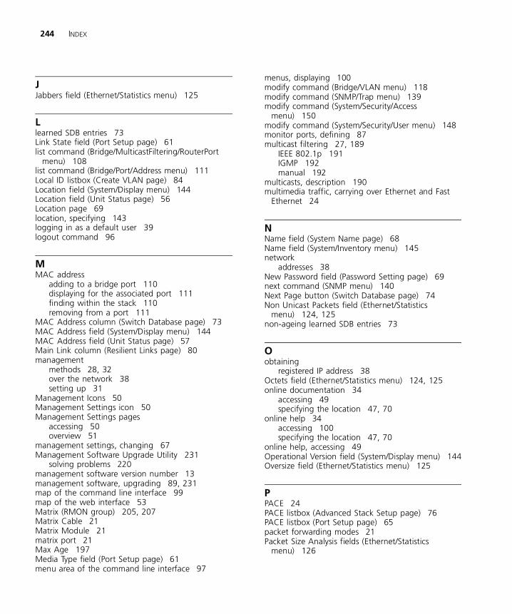
244 INDEX
JJabbers field (Ethernet/Statistics menu) 125
Llearned SDB entries 73Link State field (Port Setup page) 61list command (Bridge/MulticastFiltering/RouterPort
menu) 108list command (Bridge/Port/Address menu) 111Local ID listbox (Create VLAN page) 84Location field (System/Display menu) 144Location field (Unit Status page) 56Location page 69location, specifying 143logging in as a default user 39logout command 96
MMAC address
adding to a bridge port 110displaying for the associated port 111finding within the stack 110removing from a port 111
MAC Address column (Switch Database page) 73MAC Address field (System/Display menu) 144MAC Address field (Unit Status page) 57Main Link column (Resilient Links page) 80management
methods 28, 32over the network 38setting up 31
Management Icons 50Management Settings icon 50Management Settings pages
accessing 50overview 51
management settings, changing 67Management Software Upgrade Utility 231
solving problems 220management software version number 13management software, upgrading 89, 231map of the command line interface 99map of the web interface 53Matrix (RMON group) 205, 207Matrix Cable 21Matrix Module 21matrix port 21Max Age 197Media Type field (Port Setup page) 61menu area of the command line interface 97
menus, displaying 100modify command (Bridge/VLAN menu) 118modify command (SNMP/Trap menu) 139modify command (System/Security/Access
menu) 150modify command (System/Security/User menu) 148monitor ports, defining 87multicast filtering 27, 189
IEEE 802.1p 191IGMP 192manual 192
multicasts, description 190multimedia traffic, carrying over Ethernet and Fast
Ethernet 24
NName field (System Name page) 68Name field (System/Inventory menu) 145network
addresses 38New Password field (Password Setting page) 69next command (SNMP menu) 140Next Page button (Switch Database page) 74Non Unicast Packets field (Ethernet/Statistics
menu) 124, 125non-ageing learned SDB entries 73
Oobtaining
registered IP address 38Octets field (Ethernet/Statistics menu) 124, 125online documentation 34
accessing 49specifying the location 47, 70
online help 34accessing 100specifying the location 47, 70
online help, accessing 49Operational Version field (System/Display menu) 144Oversize field (Ethernet/Statistics menu) 125
PPACE 24PACE listbox (Advanced Stack Setup page) 76PACE listbox (Port Setup page) 65packet forwarding modes 21Packet Size Analysis fields (Ethernet/Statistics
menu) 126

INDEX 245
page area of the web interface 48, 50making changes in 53navigating 52
Pair State column (Resilient Links page) 80password command (System menu) 147password dialog 44Password Setting page 68passwords
changing 68, 147default 39entering 45, 47of default users 39
path costs. See port costspermanent SDB entries 73ping command (IP menu) 136Port column (Switch Database page) 73port costs, default 196Port field (Port Setup page) 61Port Filter listbox (Switch Database page) 74Port Graph page 92port information, displaying for the current
switch 111port mirroring. See roving analysisPort Setup page 59Port Speed field (Port Setup page) 61Port Speed listbox (Console Port Configuration
page) 67Port State listbox (Port Setup page) 64port statistics
displaying 92interpreting 94
Port Summary page 55Port Trunk Setup page 81port trunks 25, 157
displaying ports that belong to 82example 160placing ports in 82setting up 81
Port Trunks Available listbox (Port Trunk Setup page) 82
portMode command (Ethernet menu) 121ports
color-coding 54configuring 120displaying the status of 54, 126enabling and disabling 120
portState command (Ethernet menu) 120Position field (System/Inventory menu) 145priority in STP 196problem solving 213
problemscommand line interface 216Management Software Upgrade Utility 220Serial Web Utility 219SNMP management 218web interface 214
Product Number field (System/Display menu) 144
RRAP. See roving analysisReceived Stats fields (Ethernet/Statistics menu) 124refreshing the Switch graphic 55registered IP address, obtaining 38Remote Monitoring. See RMONremoteAccess command (System menu) 151remove command (Bridge/Port/Address menu) 111remove command (Feature/Analyzer menu) 128remove command (Feature/Resilience menu) 131remove command (SNMP/Trap menu) 139remove command (System/Security/User menu) 149removePort command
(bridge/multicastFiltering/routerPort menu) 109removePort command (Bridge/VLAN menu) 119removePort command (Feature/Trunk menu) 133reset command (System menu) 151Reset page 88resetting the stack 88, 151resilient link pairs
creating 80deleting 81displaying 80swapping the main and standby ports 81
resilient links 25, 79displaying information via CLI 131remove via CLI 131setting up via CLI 130swapping over active links via CLI 131
Resilient Links page 79RMON 27
alarm events 208benefits 206default alarm settings 208groups 204probe 204
Root Bridge 196Root Path Cost 197Root Port 197router port, manually identifying a port 108router port,removing 109router ports
displaying all 108
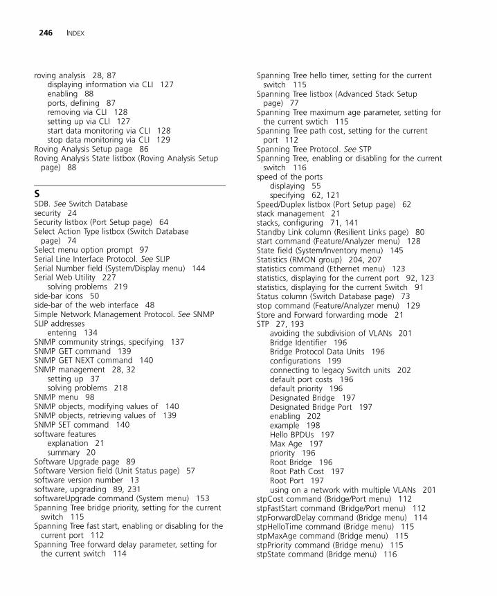
246 INDEX
roving analysis 28, 87displaying information via CLI 127enabling 88ports, defining 87removing via CLI 128setting up via CLI 127start data monitoring via CLI 128stop data monitoring via CLI 129
Roving Analysis Setup page 86Roving Analysis State listbox (Roving Analysis Setup
page) 88
SSDB. See Switch Databasesecurity 24Security listbox (Port Setup page) 64Select Action Type listbox (Switch Database
page) 74Select menu option prompt 97Serial Line Interface Protocol. See SLIPSerial Number field (System/Display menu) 144Serial Web Utility 227
solving problems 219side-bar icons 50side-bar of the web interface 48Simple Network Management Protocol. See SNMPSLIP addresses
entering 134SNMP community strings, specifying 137SNMP GET command 139SNMP GET NEXT command 140SNMP management 28, 32
setting up 37solving problems 218
SNMP menu 98SNMP objects, modifying values of 140SNMP objects, retrieving values of 139SNMP SET command 140software features
explanation 21summary 20
Software Upgrade page 89Software Version field (Unit Status page) 57software version number 13software, upgrading 89, 231softwareUpgrade command (System menu) 153Spanning Tree bridge priority, setting for the current
switch 115Spanning Tree fast start, enabling or disabling for the
current port 112Spanning Tree forward delay parameter, setting for
the current switch 114
Spanning Tree hello timer, setting for the current switch 115
Spanning Tree listbox (Advanced Stack Setup page) 77
Spanning Tree maximum age parameter, setting for the current swtich 115
Spanning Tree path cost, setting for the current port 112
Spanning Tree Protocol. See STPSpanning Tree, enabling or disabling for the current
switch 116speed of the ports
displaying 55specifying 62, 121
Speed/Duplex listbox (Port Setup page) 62stack management 21stacks, configuring 71, 141Standby Link column (Resilient Links page) 80start command (Feature/Analyzer menu) 128State field (System/Inventory menu) 145Statistics (RMON group) 204, 207statistics command (Ethernet menu) 123statistics, displaying for the current port 92, 123statistics, displaying for the current Switch 91Status column (Switch Database page) 73stop command (Feature/Analyzer menu) 129Store and Forward forwarding mode 21STP 27, 193
avoiding the subdivision of VLANs 201Bridge Identifier 196Bridge Protocol Data Units 196configurations 199connecting to legacy Switch units 202default port costs 196default priority 196Designated Bridge 197Designated Bridge Port 197enabling 202example 198Hello BPDUs 197Max Age 197priority 196Root Bridge 196Root Path Cost 197Root Port 197using on a network with multiple VLANs 201
stpCost command (Bridge/Port menu) 112stpFastStart command (Bridge/Port menu) 112stpForwardDelay command (Bridge menu) 114stpHelloTime command (Bridge menu) 115stpMaxAge command (Bridge menu) 115stpPriority command (Bridge menu) 115stpState command (Bridge menu) 116
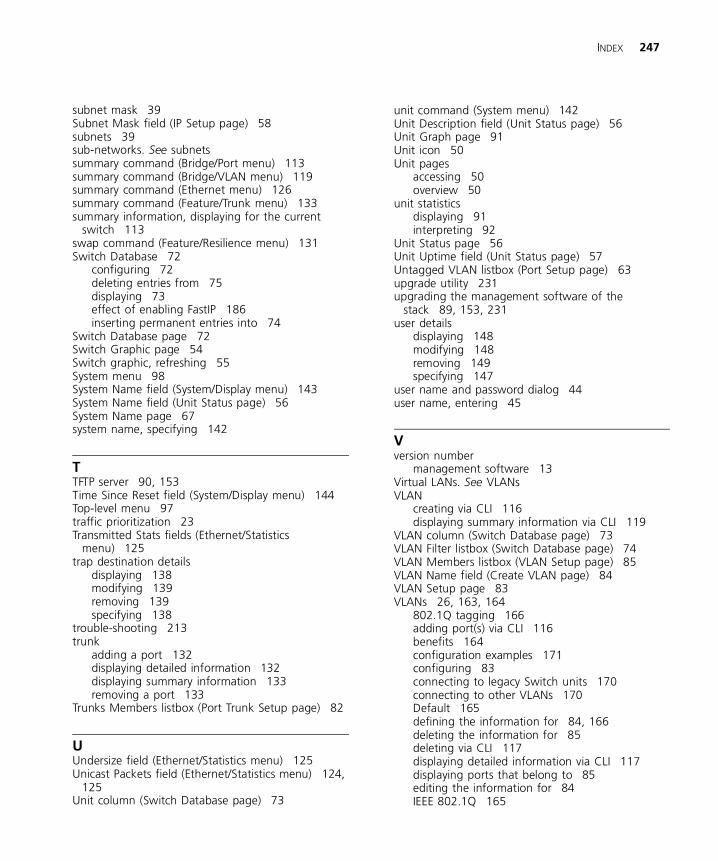
INDEX 247
subnet mask 39Subnet Mask field (IP Setup page) 58subnets 39sub-networks. See subnetssummary command (Bridge/Port menu) 113summary command (Bridge/VLAN menu) 119summary command (Ethernet menu) 126summary command (Feature/Trunk menu) 133summary information, displaying for the current
switch 113swap command (Feature/Resilience menu) 131Switch Database 72
configuring 72deleting entries from 75displaying 73effect of enabling FastIP 186inserting permanent entries into 74
Switch Database page 72Switch Graphic page 54Switch graphic, refreshing 55System menu 98System Name field (System/Display menu) 143System Name field (Unit Status page) 56System Name page 67system name, specifying 142
TTFTP server 90, 153Time Since Reset field (System/Display menu) 144Top-level menu 97traffic prioritization 23Transmitted Stats fields (Ethernet/Statistics
menu) 125trap destination details
displaying 138modifying 139removing 139specifying 138
trouble-shooting 213trunk
adding a port 132displaying detailed information 132displaying summary information 133removing a port 133
Trunks Members listbox (Port Trunk Setup page) 82
UUndersize field (Ethernet/Statistics menu) 125Unicast Packets field (Ethernet/Statistics menu) 124,
125Unit column (Switch Database page) 73
unit command (System menu) 142Unit Description field (Unit Status page) 56Unit Graph page 91Unit icon 50Unit pages
accessing 50overview 50
unit statisticsdisplaying 91interpreting 92
Unit Status page 56Unit Uptime field (Unit Status page) 57Untagged VLAN listbox (Port Setup page) 63upgrade utility 231upgrading the management software of the
stack 89, 153, 231user details
displaying 148modifying 148removing 149specifying 147
user name and password dialog 44user name, entering 45
Vversion number
management software 13Virtual LANs. See VLANsVLAN
creating via CLI 116displaying summary information via CLI 119
VLAN column (Switch Database page) 73VLAN Filter listbox (Switch Database page) 74VLAN Members listbox (VLAN Setup page) 85VLAN Name field (Create VLAN page) 84VLAN Setup page 83VLANs 26, 163, 164
802.1Q tagging 166adding port(s) via CLI 116benefits 164configuration examples 171configuring 83connecting to legacy Switch units 170connecting to other VLANs 170Default 165defining the information for 84, 166deleting the information for 85deleting via CLI 117displaying detailed information via CLI 117displaying ports that belong to 85editing the information for 84IEEE 802.1Q 165
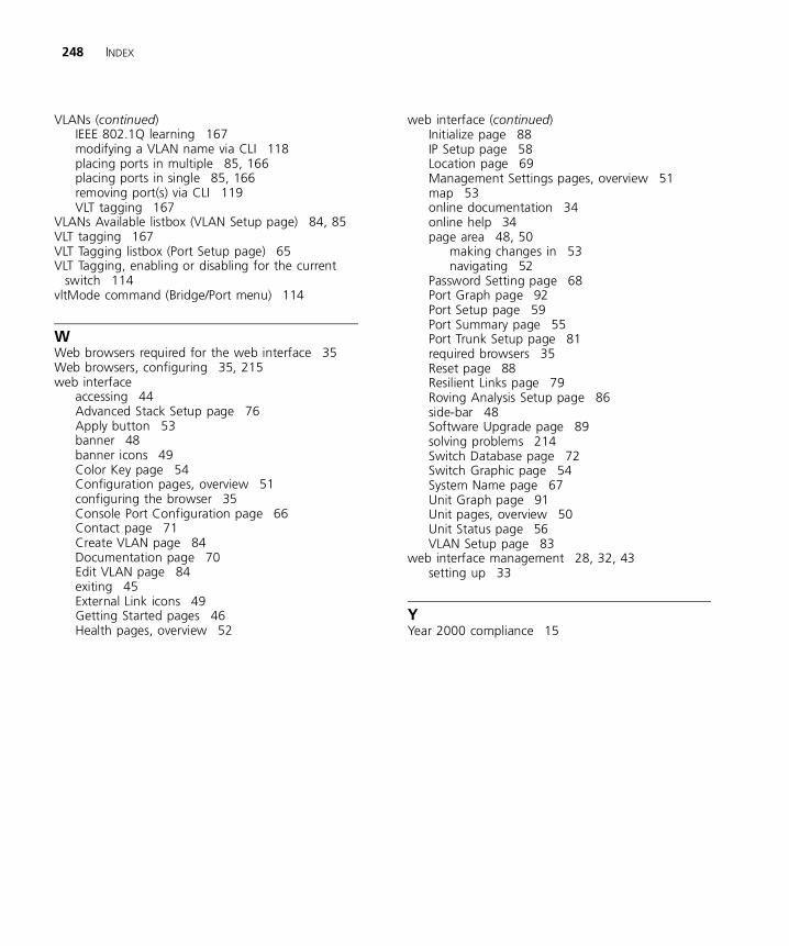
248 INDEX
VLANs (continued)IEEE 802.1Q learning 167modifying a VLAN name via CLI 118placing ports in multiple 85, 166placing ports in single 85, 166removing port(s) via CLI 119VLT tagging 167
VLANs Available listbox (VLAN Setup page) 84, 85VLT tagging 167VLT Tagging listbox (Port Setup page) 65VLT Tagging, enabling or disabling for the current
switch 114vltMode command (Bridge/Port menu) 114
WWeb browsers required for the web interface 35Web browsers, configuring 35, 215web interface
accessing 44Advanced Stack Setup page 76Apply button 53banner 48banner icons 49Color Key page 54Configuration pages, overview 51configuring the browser 35Console Port Configuration page 66Contact page 71Create VLAN page 84Documentation page 70Edit VLAN page 84exiting 45External Link icons 49Getting Started pages 46Health pages, overview 52
web interface (continued)Initialize page 88IP Setup page 58Location page 69Management Settings pages, overview 51map 53online documentation 34online help 34page area 48, 50
making changes in 53navigating 52
Password Setting page 68Port Graph page 92Port Setup page 59Port Summary page 55Port Trunk Setup page 81required browsers 35Reset page 88Resilient Links page 79Roving Analysis Setup page 86side-bar 48Software Upgrade page 89solving problems 214Switch Database page 72Switch Graphic page 54System Name page 67Unit Graph page 91Unit pages, overview 50Unit Status page 56VLAN Setup page 83
web interface management 28, 32, 43setting up 33
YYear 2000 compliance 15