Superlift Contractor - Parts, Service and Operations Manuals
46
Service Manual Serial Number Range Superlift Contractor from 9595-101 to 9501-19014 from SLC02-19015 to SLC16-66775 from SLC16G-66776 to SLC16G-70799 from SLCG-70800 Part No. 115409 Rev A2 June 2018
Transcript of Superlift Contractor - Parts, Service and Operations Manuals

Service Manual
Serial Number Range
Superlift Contractor
from 9595-101 to 9501-19014
from SLC02-19015 to
SLC16-66775
from SLC16G-66776 to SLC16G-70799
from SLCG-70800
Part No. 115409 Rev A2 June 2018

Service Manual June 2018
Introduction
ii Superlift Contractor Part No. 115409
Intr oducti on Intr oducti on
Important Read, understand and obey the safety rules and operating instructions in the appropriate Operator's Manual on your machine before attempting any maintenance procedure.
This manual provides detailed scheduled maintenance information for the machine owner and user. It also provides troubleshooting and repair procedures for qualified service professionals.
Basic mechanical, hydraulic and electrical skills are required to perform most procedures. However, several procedures require specialized skills, tools, lifting equipment and a suitable workshop. In these instances, we strongly recommend that maintenance and repair be performed at an authorized Genie dealer service center.
Technical Publications Genie has endeavored to deliver the highest degree of accuracy possible. However, continuous improvement of our products is a Genie policy. Therefore, product specifications are subject to change without notice.
Readers are encouraged to notify Genie of errors and send in suggestions for improvement. All communications will be carefully considered for future printings of this and all other manuals.
Contact Us: Internet: www.genielift.com E-mail: [email protected]
Serial Number Information Genie Industries offers the following Service Manuals for these models:
Title Part No.
Genie Superlift Contractor Parts and Service Manual,First Edition(before serial number 9595-101)....................................................33953
Genie Superlift Contractor Parts and Service Manual,Second Edition(from serial number 9595-101)...................................................*80140
*Note: Genie Superlift Contractor Service Manual115409 and Genie Superlift Contractor Part's Manual115410 replaces Genie Superlift Contractor Parts andService Manual 80140.
Find a Manual for this Model Go to http://www.genielift.com
Use the links to locate Service Manuals, Maintenance Manuals, Service and Repair Manuals, Parts Manuals and Operator's Manuals.
Copyright © 1995 by Genie Industries
115409 Rev A, February 2009
Third Edition, First Printing
'Genie'' and "SLC" are registered trademarks of Terex South Dakota. in the U.S.A. and many other countries.

June 2018 Service Manual
Introduction
Part No. 115409 Superlift Contractor iii
Revision History Revision Date Section Procedure / Page / Description A 2/2009 Initial Release
A1 9/2016 Introduction Serial Number Legend
A2 6/2018 Maintenance C-4
Reference Examples:
Section – Maintenance, B-3 Electronic Version
Click on any content or procedure in the Table of Contents to view the update.
Section – Repair Procedure, 4-2
Section – Fault Codes, All charts
Section – Schematics, Legends and schematics

Service Manual June 2018
Introduction
iv Superlift Contractor Part No. 115409
Serial Number Legend To August 31, 2016
1 Model 2 Model year 3 Facility code
4 Sequence number 5 Serial label 6 Serial number (stamped on base)
From September 1, 2016
1 Model 2 Facility code 3 Sequence number
4 Serial label 5 Serial number (stamped on base)

June 2018 Service Manual
Safety Rules
Part No. 115409 Superlift Contractor v
Section 1 Safety R ules
Danger Failure to obey the instructions and safety rules in this manual and the appropriate Operator's Manual on your machine will result in death or serious injury.
Many of the hazards identified in the operator's manual are also safety hazards when maintenance and repair procedures are performed.
Do Not Perform Maintenance Unless: You are trained and qualified to perform
maintenance on this machine.
You read, understand and obey:
• manufacturer's instructions and safety rules
• employer's safety rules and worksite regulations
• applicable governmental regulations
You have the appropriate tools, lifting equipment and a suitable workshop.

Service Manual June 2018
Safety Rules
vi Superlift Contractor Part No. 115409
Personal Safety Any person working on or around a machine must be aware of all known safety hazards. Personal safety and the continued safe operation of the machine should be your top priority.
Read each procedure thoroughly. This manual and the decals on the machine, use signal words to identify the following:
Safety alert symbol—used to alert personnel to potential personal injury hazards. Obey all safety messages that follow this symbol to avoid possible injury or death.
Indicates a imminently hazardous situation which, if not avoided, will result in death or serious injury.
Indicates a potentially hazardous situation which, if not avoided, could result in death or serious injury.
Indicates a potentially hazardous situation which, if not avoided, may cause minor or moderate injury.
Indicates a potentially hazardous situation which, if not avoided, may result in property damage.
Be sure to wear protective eye wear and other protective clothing if the situation warrants it.
Be aware of potential crushing hazards such as moving parts, free swinging or unsecured components when lifting or placing loads. Always wear approved steel-toed shoes.
Workplace Safety Any person working on or around a machine must be aware of all known safety hazards. Personal safety and the continued safe operation of the machine should be your top priority.
Be sure to keep sparks, flames and lighted tobacco away from flammable and combustible materials like battery gases and engine fuels. Always have an approved fire extinguisher within easy reach.
Be sure that all tools and working areas are properly maintained and ready for use. Keep work surfaces clean and free of debris that could get into machine components and cause damage.
Be sure any forklift, overhead crane or other lifting or supporting device is fully capable of supporting and stabilizing the weight to be lifted. Use only chains or straps that are in good condition and of ample capacity.
Be sure that fasteners intended for one time use (i.e., cotter pins and self-locking nuts) are not reused. These components may fail if they are used a second time.
Be sure to properly dispose of old oil or other fluids. Use an approved container. Please be environmentally safe.
Be sure that your workshop or work area is properly ventilated and well lit.
June 2018
Table of Contents
Part No. 115409 Superlift Contractor vii
Introduction Introduction ........................................................................................................... ii Important Information ............................................................................................. ii
Find a Manual for this Model .................................................................................. ii
Revision History..................................................................................................... iii
Serial Number Legend .......................................................................................... iv
Section 1 Safety Rules .......................................................................................................... v General Safety Rules ............................................................................................. v
Section 2 Specifications ....................................................................................................... 9 Specifications ......................................................................................................... 9
SAE and Metric Fasteners Torque Charts ........................................................... 11
Section 3 Scheduled Maintenance Procedures ............................................................... 12 Introduction ........................................................................................................... 12
Pre-Delivery Preparation Report .......................................................................... 15
Maintenance Inspection Report............................................................................ 17
Checklist A Procedures ..................................................................................... 19 A-1 Inspect the Manuals and Decals.................................................................... 19
A-2 Perform Pre-operation Inspection .................................................................. 20
A-3 Perform Function Tests ................................................................................. 20
Checklist B Procedures ..................................................................................... 21 B-1 Inspect All Welds ........................................................................................... 21
B-2 Clean the Columns ........................................................................................ 21
B-3 Check the Winch Operation ........................................................................... 22
B-4 Inspect the Carriage Hold-down Bar ............................................................. 22
B-5 Inspect and Lubricate the Winch ................................................................... 23

June 2018
Table of Contents
viii Superlift Contractor Part No. 115409
Checklist C Procedures ..................................................................................... 24 C-1 Inspect the Mast Assembly for Wear ........................................................... 24
C-2 Inspect the Safety Brake System (if equipped) ............................................. 25
C-3 Replace the Winch Friction Disks ................................................................. 27
C-4 Inspect the Cable and Cable Pulleys ............................................................ 27
C-5 Lubricate the Casters and Wheels ................................................................ 28
C-6 Inspect the Painted Surfaces ........................................................................ 28
Section 4 Repair Procedures ............................................................................................. 29
Base Assembly................................................................................................... 30 1-1 How to Remove the Base .............................................................................. 30
Mast Assembly ................................................................................................... 31 2-1 How to Disassemble the Mast Assembly ...................................................... 31
Cable Routing ...................................................................................................... 34
2-2 Lifting Cable ................................................................................................... 35
2-3 Lifting Pulley................................................................................................... 37
Winches .............................................................................................................. 38 3-1 One-speed Winch .......................................................................................... 38
One-speed Winch Assembly - ANSI .................................................................... 40
3-2 Two-speed Winch .......................................................................................... 42
Two-speed Winch Assembly ................................................................................ 44

June 2018 Service Manual
Specifications
Part No. 115409 Superlift Contractor 9
Section 2 Specificati ons
Model SLC-6 SLC-12 SLC-18 SLC-24 Height-stowed 86 in 86 in 86 in 86 in 2.2 m 2.2 m 2.2 m 2.2 m Width 31.5 in 31.5 in 31.5 in 31.5 in Standard Base 80 cm 80 cm 80 cm 80 cm
Width-stabilizers lowered 66 in 66 in 66 in 66 in (if equipped) 1.7 m 1.7 m 1.7 m 1.7 m Length - Stowed 34 in 34 in 34 in 34 in 86.4 cm 86.4 cm 86.4 cm 86.4 cm Length - Operating 59 in 63 in 73 in 81 in 1.5 m 1.6 m 1.9 m 2 m Ground 2 in 2 in 2 in 2 in Clearance 5.8 cm 5.8 cm 5.8 cm 5.8 cm
Load Capacity 650 lbs 650 lbs 650 lbs 650 lbs at 14in / 36cm load center 295 kg 295 kg 295 kg 295 kg 650 lbs 650 lbs 650 lbs 650 lbs Note: see Load Capacity Charts section for load capacities at other load centers.
Net Weight 165 lbs 225 lbs 307 lbs 347 lbs 75 kg 102 kg 139 kg 157 kg
Airborne Noise Emissions by Machinery 85 dB 85 dB 85 dB 85 dB Maximum sound level at normal operating work stations (A-weighted)
Load Handling Attachments Length Width Depth Net Weight Standard Forks 28 in 23 in 2.5 in 26.5 lbs 71.1 cm 58.4 cm 6.4 cm 12 kg Adjustable Forks 27.5 in 11.5 in to 30 in 2.5 in 52.5 lbs 69.9 cm 29.2 cm to 76.2 cm 6.4 cm 23.8 kg
Boom 44 in 1.5 in 6 in 40 lbs 111.8 cm 3.8 cm 15.2 cm 18 kg Pipe Cradle 27.5 in 24.5 in 6 in 10 lbs 70 cm 63 cm 15.2 cm 4.5 kg Load Platform 26.3 in 23 in 2.5 24 lbs 69.9 cm 58.4 cm 6.4 cm 11 kg Fork extensions (each) 30 in 2 in 3 in 4.5 lbs 76 cm 5 cm 7.6 cm 2 kg

Service Manual June 2018
Specifications
10 Superlift Contractor Part No. 115409
Dimensions-Operating SLC-6 SLC-12 SLC-18 SLC-24 Standard Forks Forks Down 5 ft 8 in 11 ft 2in 16 ft 9 in 22 ft 3 in 1.7 m 3.4 m 5.1 m 6.8 m
Forks Up 7 ft 5 in 12 ft 11 in 18 ft 6 in 24 ft 2.3 m 3.9 m 5.6 m 7.3 m
Adjustable Forks Forks Down 5 ft 8 in 9 ft 9 in 14 ft 7.5 in 19 ft 6 in 1.7 m 3 m 4.5 m 5.9 m
Forks Up 6 ft 7 in 2.3 m
11 ft 5.5 m 3.9 m
16 ft 4 in 5.6 m
21 ft 2.5 in 7.3 m
Boom 6 ft 8 in 12 ft 2 in 17 ft 9 in 23 ft 3 in
2 m 3.7 m 5.4 m 7.1 m
Note: measured from ground to bottom of shackle Load Platform Forks Down 5ft 8 in 11 ft 2 in 16 ft 6 in 22 ft 3 in 1.7 m 3.4 m 5.1 m 6.8 m
Forks Up 7 ft 5 in 12 ft 11 in 18 ft 6 in 24 ft 2.3 m 3.9 m 5.6 m 7.3 m
Note: Can be used with standard forks and adjustable forks only Pipe Cradle Option: handles round objects up to 30 in / 76 cm in diameter Note: Can be used with standard forks and adjustable forks only (see above for working heights) Non-marking Fork Option Note: Can be used with standard forks and adjustable forks only (see above for working heights) Fork Extension Option Note: can be used with standard forks and adjustable forks only (see above for working heights)

June 2018 Service Manual
Specifications
Part No. 115409 Superlift Contractor 11
Service Manual June 2018
Scheduled Maintenance Procedures
12 Superlift Contractor Part No. 115409
Section 3 Schedul ed Mai ntenance Pr ocedures
Observe and Obey: Maintenance inspections shall be completed
by a person trained and qualified on the maintenance of this machine.
Scheduled maintenance inspections shall be completed daily, quarterly, and annually as specified on the Maintenance inspection Report. The frequency and extent of periodic examinations and tests may also depend on national regulations.
Failure to perform each procedure as presented and scheduled may cause death, serious injury or substantial damage.
Immediately tag and remove from service a damaged or malfunctioning machine.
Repair any machine damage or malfunction before operating the machine.
Use only Genie approved replacement parts.
Machines that have been out of service for a period longer than 3 months must complete the quarterly inspection.
Unless otherwise specified, perform each procedure with the machine in the following configuration:
• Machine parked on a firm, level surface
• Carriage fully lowered
• Casters locked
• Load handling attachment installed
About This Section This section contains detailed procedures for each scheduled maintenance inspection.
Each procedure includes a description, safety warnings and step-by-step instructions.
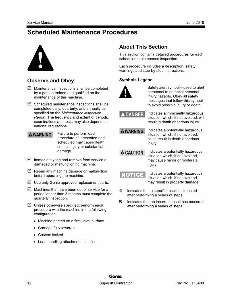
Symbols Legend
Safety alert symbol—used to alert personnel to potential personal injury hazards. Obey all safety messages that follow this symbol to avoid possible injury or death.
Indicates a imminently hazardous situation which, if not avoided, will result in death or serious injury.
Indicates a potentially hazardous situation which, if not avoided, could result in death or serious injury.
Indicates a potentially hazardous situation which, if not avoided, may cause minor or moderate injury.
Indicates a potentially hazardous situation which, if not avoided, may result in property damage.
Indicates that a specific result is expected after performing a series of steps.
Indicates that an incorrect result has occurred after performing a series of steps.

June 2018 Service Manual
Scheduled Maintenance Procedures
Part No. 115409 Superlift Contractor 13
Maintenance Symbols Legend Note: The following symbols have been used in this manual to help communicate the intent of the instructions. When one or more of the symbols appear at the beginning of a maintenance procedure, it conveys the meaning below.
Indicates that tools will be required to perform this procedure.
Indicates that new parts will be required to perform this procedure.
Indicates that dealer service will be required to perform this procedure.
Pre-delivery Preparation Report The pre-delivery preparation report contains checklists for each type of scheduled inspection.
Make copies for each inspection. Store completed forms as required.
Maintenance Schedule The Scheduled Maintenance Procedures section and the Maintenance Inspection Report have been divided into subsections. Use the following chart to determine which group(s) of procedures are required to perform a scheduled inspection.
Inspection Checklist Daily or every 8 hours A Quarterly or every 250 hours A + B
Annually or every 1000 hours A + B + C
Maintenance Inspection Report The maintenance inspection report contains checklists for each type of scheduled inspection.
Make copies of the Maintenance Inspection Report to use for each inspection. Maintain completed forms for a minimum of 4 years or in compliance with your employer, jobsite and governmental regulations and requirements.

Service Manual June 2018
14 Superlift Contractor Part No. 115409
This page intentionally left blank.

June 2018 Service Manual
Pre-Delivery Preparation Report
Fundamentals It is the responsibility of the owner or dealer to perform the Pre-delivery Preparation.
The Pre-delivery Preparation is performed prior to each delivery. The inspection is designed to discover if anything is apparently wrong with a machine before it is put into service.
A damaged or modified machine must never be used. If damage or any variation from factory delivered condition is discovered, the machine must be tagged and removed from service.
Repairs to the machine may only be made by a qualified service technician, according to the manufacturer's specifications.
Scheduled maintenance inspections shall be performed by qualified service technicians, according to the manufacturer's specifications and the requirements listed in the responsibilities manual.
Instructions Use the operator’s manual on your machine.
The Pre-delivery Preparation consists of completing the Pre-operation Inspection, the Maintenance items and the Function Tests.
Use this form to record the results. Place a check in the appropriate box after each part is completed. Follow the instructions in the operator’s manual.
If any inspection receives an N, remove the machine from service, repair and re-inspect it. After repair, place a check in the R box.
Legend Y = yes, acceptable N = no, remove from service R = repaired
Comments Pre-delivery Preparation Y N R Pre-operation inspection completed
Maintenance items completed
Function tests completed
Model
Serial number Date Machine owner Inspected by (print) Inspector signature Inspector title Inspector company

Service Manual June 2018
16 Superlift Contractor Part No. 115409
This page intentionally left blank.

June 2018 Service Manual
Maintenance Inspection Report
Part No. 115409 Superlift Contractor 17
Model
Serial number
Date
Hour meter
Machine owner
Inspected by (print)
Inspector signature
Inspector title
Inspector company
Instructions • Make copies of this report to use for
each inspection. • Select the appropriate checklist(s) for
the type of inspection(s) to perform.
Daily or every 8 hours A Quarterly or every
250 hours A + B
Annually or every 1000 hours
A + B + C
• Place a check in the appropriate box after each inspection procedure is completed.
• Use the step-by-step procedures in this section to learn how to perform these inspections.
• If any inspection receives an "N," tag and remove the machine from service, repair and re-inspect it. After repair, place a check in the "R" box.
Legend
Y = yes, acceptable N = no, remove from service R = repaired
Checklist A- Rev A Y N R
A-1 Inspect the manuals and decals
A-2 Pre-operation inspection
A-3 Function tests
Checklist B Y N R
B-1 Welds
B-2 Clean columns
B-3 Winch operation
B-4 Carriage hold down bar
B-5 Inspect and lubricate winch
Comments
Checklist C- Rev A Y N R
C-1 Mast assembly wear
C-2 Safety brake system (if equipped)
C-3 Replace winch friction disk
C-4 Inspect cable and pulleys
C-5 Lubricate the casters and wheels
C-6 Painted surfaces
Comments

Service Manual June 2018
18 Superlift Contractor Part No. 115409
This page intentionally left blank.

June 2018 Service Manual
Checklist A Procedures
Part No. 115409 Superlift Contractor 19
A-1 Inspect the Manuals and Decals Genie specifications require that this procedure be performed every 8 hours or daily, whichever comes first.
Maintaining the operator’s and safety manuals in good condition is essential to safe machine operation. Manuals are included with each machine and should be stored in the container provided in the platform. An illegible or missing manual will not provide safety and operational information necessary for a safe operating condition.
In addition, maintaining all of the safety and instructional decals in good condition is mandatory for safe machine operation. Decals alert operators and personnel to the many possible hazards associated with using this machine. They also provide users with operation and maintenance information. An illegible decal will fail to alert personnel of a procedure or hazard and could result in unsafe operating conditions.
1 Check to make sure that the operator's, safety and responsibilities manuals are present and complete in the storage container on the platform.
2 Examine the pages of each manual to be sure that they are legible and in good condition.
Result: The operator's manual is appropriate for the machine and all manuals are legible and in good condition.
Result: The operator's manual is not appropriate for the machine or all manuals are not in good condition or is illegible. Remove the machine from service until the manual is replaced.
3 Open the operator's manual to the decals inspection section. Carefully and thoroughly inspect all decals on the machine for legibility and damage.
Result: The machine is equipped with all required decals, and all decals are legible and in good condition.
Result: The machine is not equipped with all required decals, or one or more decals are illegible or in poor condition. Remove the machine from service until the decals are replaced.
4 Always return the manuals to the storage container after use.
Note: Contact your authorized Genie distributor or Genie if replacement manuals or decals are needed.

Service Manual June 2018
Checklist A Procedures
20 Superlift Contractor Part No. 115409
A-2 Perform Pre-operation Inspection Genie specifications require that this procedure be performed every 8 hours or daily, whichever comes first.
Completing a Pre-operation Inspection is essential to safe machine operation. The Pre-operation Inspection is a visual inspection performed by the operator prior to each work shift. The inspection is designed to discover if anything is apparently wrong with a machine before the operator performs the function tests. The Pre-operation Inspection also serves to determine if routine maintenance procedures are required.
Complete information to perform this procedure is available in the appropriate operator's manual. Refer to the Operator's Manual on your machine.
A-3 Perform Function Tests Genie specifications require that this procedure be performed every 8 hours or daily, whichever comes first.
Completing the function tests is essential to safe machine operation. Function tests are designed to discover any malfunctions before the machine is put into service. A malfunctioning machine must never be used. If malfunctions are discovered, the machine must be tagged and removed from service.
Complete information to perform this procedure is available in the appropriate operator's manual. Refer to the Operator's Manual on your machine.

June 2018 Service Manual
Checklist B Procedures
Part No. 115409 Superlift Contractor 21
B-1 Inspect All Welds Genie specifications require that this procedure be performed every 250 hours or quarterly, whichever comes first.
Weld inspections are essential to safe machine operation and good machine performance. Failure to locate and repair damage may result in an unsafe operating condition.
1 Visually inspect the welds in the following locations:
• Winch mounting plate
• Loading wheels/steer handle
• Base
• Legs and stabilizers
• Load handling attachment(s)
B-2 Clean the Columns
Genie requires that this procedure be performed every 250 hours or quarterly, whichever comes first.
Clean columns are essential to good machine performance and safe operation. Extremely dirty conditions may require that the columns be cleaned more often.
1 Raise all columns to full height.
2 Visually inspect the inner and outer channels of the columns for debris or foreign material. If necessary, use a mild cleaning solvent to clean the columns.
Bodily injury hazard. This procedure will require the use of additional access equipment. Do not place ladders or scaffold on or against any part of the machine. Performing this procedure without the proper skills and tools could result in death or serious injury. Dealer service is strongly recommended.

Service Manual June 2018
Checklist B Procedures
22 Superlift Contractor Part No. 115409
B-3 Check the Winch Operation Genie specifications require that this procedure be performed every 250 hours or quarterly, whichever comes first.
Detection of damage to the winch is essential to safe machine operation. An unsafe working condition exists if the winch is damaged or not operating correctly. A daily check of the winch operation allows the inspector to identify changes in the operating condition of the winch that might indicate damage.
1 Visually inspect all the winch components for damage.
2 Raise the carriage through a partial cycle and release the winch handles.
Result: The winch should operate smoothly, free of hesitation or binding. The load should not lower when the handles are released.
3 Fully lower the carriage.
Result: The winch should operate smoothly, free of hesitation or binding.
B-4 Inspect the Carriage Hold-down Bar Genie specifications require that this procedure be performed every 250 hours or quarterly, whichever comes first.
Detection of damage to the column hold down system is essential for safe machine operation. An unsafe working condition exists if the system is damaged and does not operate properly.
1 Using proper lifting techniques, lay the machine back against a sawhorse or other suitable support.
2 Visually inspect the carriage hold-down bar for damage.
3 Check the carriage hold-down bar for smooth operation.

June 2018 Service Manual
Checklist B Procedures
Part No. 115409 Superlift Contractor 23
B-5 Inspect and Lubricate the Winch
Genie specifications require that this procedure be performed every 250 hours or quarterly, whichever comes first.
Maintaining the winch is essential to good machine performance and safe operation. An unsafe working condition exists if the winch has excessive wear and/or does not operate smoothly, free of hesitation and binding.
1 Carefully lubricate the following areas with automotive grease:
• Cable drum gear
• Teeth on the pinion gear that mesh with the cable drum gear
• Threads on the pinion shaft, under the pinion gear
• Models with Two-speed winch: The teeth on the slow and the fast speed gears where they mesh together
Note: Do not apply grease to brake friction disk or ratchet gear.
2 Carefully lubricate both pivot points on each ratchet pawl with 30W oil.
3 Measure each friction disk for wear. Replace the friction disk if it measures less than specification.
Friction disk specification Thickness, minimum 0.065 inch
1.5 mm
4 Measure both shaft bushings for wear. Replace the bushings if the wall thickness measurements are less than specification.
Pinion shaft bushing specification Wall thickness, minimum 0.125 inch
3.1 mm
5 Lubricate the surface of the frame drum spacer with a thin layer of lithium grease. Tighten the drum bolt to 20 ft-lbs / 27 Nm. Do not over tighten.
Service Manual June 2018
Checklist C Procedures
24 Superlift Contractor Part No. 115409
C-1 Inspect the Mast Assembly for Wear
Genie specifications require that this procedure be performed every 1000 hours or annually, whichever comes first.
Detection of excessive or unusual wear in the mast assembly is essential for safe machine operation. An unsafe working condition exists if the mast assembly has excessive wear and/or does not operate smoothly, free of hesitation and binding.
1 Attach a lifting strap from an overhead crane or similar lifting device to the lifting point on the top of the mast. Rotate the carriage hold-down bar over the carriage and operate the winch to apply tension to the lifting cable.
2 Lift the machine slightly with the overhead crane and guide it onto a suitable structure capable of supporting it.
Crushing hazard. The machine will fall if not properly supported by the overhead crane.
3 Lower the top of the mast onto the suitable structure.
4 Attach a lifting strap from an overhead crane to the base of the machine.
5 Lift the base with the overhead crane, until the mast is level and place another suitable structure under the mast.
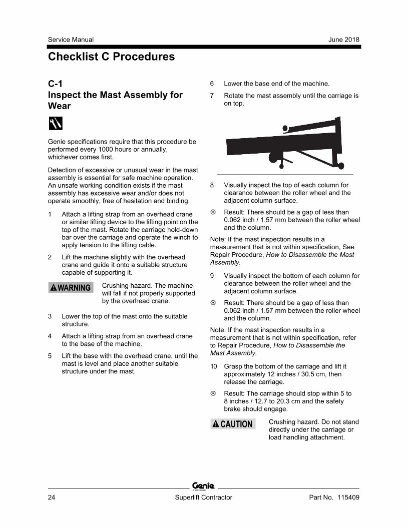
6 Lower the base end of the machine.
7 Rotate the mast assembly until the carriage is on top.
8 Visually inspect the top of each column for clearance between the roller wheel and the adjacent column surface.
Result: There should be a gap of less than 0.062 inch / 1.57 mm between the roller wheel and the column.
Note: If the mast inspection results in a measurement that is not within specification, See Repair Procedure, How to Disassemble the Mast Assembly.
9 Visually inspect the bottom of each column for clearance between the roller wheel and the adjacent column surface.
Result: There should be a gap of less than 0.062 inch / 1.57 mm between the roller wheel and the column.
Note: If the mast inspection results in a measurement that is not within specification, refer to Repair Procedure, How to Disassemble the Mast Assembly.
10 Grasp the bottom of the carriage and lift it approximately 12 inches / 30.5 cm, then release the carriage.
Result: The carriage should stop within 5 to 8 inches / 12.7 to 20.3 cm and the safety brake should engage.
Crushing hazard. Do not stand directly under the carriage or load handling attachment.

June 2018 Service Manual
Checklist C Procedures
Part No. 115409 Superlift Contractor 25
C-2 Inspect the Safety Brake System (if equipped)
Genie specifications require that this procedure be performed every 1000 hours or annually, whichever comes first.
Detection of damage or a faulty safety brake system is essential for safe machine operation. An unsafe working condition exists if the system is damaged or faulty and does not allow the mast to sequence properly, free of hesitation and binding.
Bodily injury hazard. This procedure requires specific repair skills, lifting equipment and a suitable workshop. Attempting this procedure without these skills and tools could result in death or serious injury and significant component damage. Dealer service is strongly recommended.
Bodily injury hazard. Beware of sharp edges. Wear protective gloves when performing this procedure.
1 Fasten a load handling attachment to the carriage (use the forks or the boom if possible).Do not place any weight on the load handling attachment.
2 Raise the carriage until it is half way up the front column
3 Grasp the bottom carriage and lift it approximately 5 inches / 12.7 cm, then release the carriage.
Result: The carriage should stop within 3 inches / 7.6 cm and the safety brake should engage.
Crushing hazard. Do not stand directly under the carriage or load handling attachment.
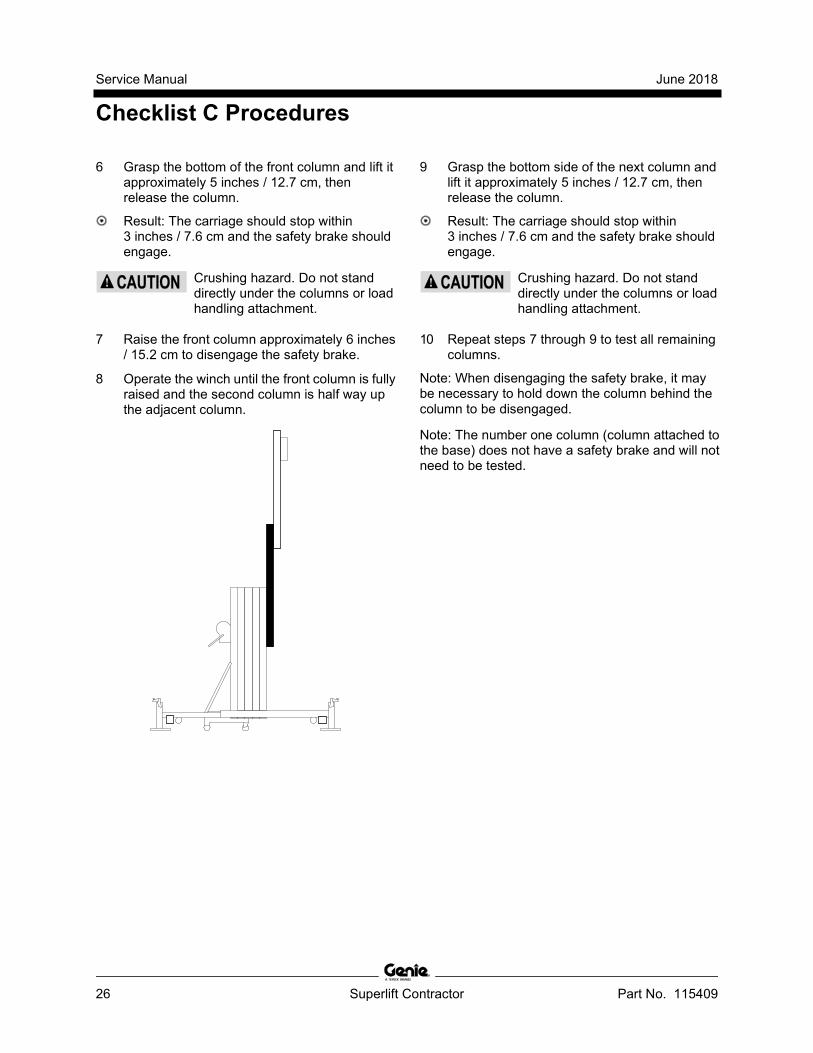
4 Raise the carriage approximately 6 inches / 15.2 cm to disengage the safety brake.
5 Operate the winch until the front column is half way up the adjacent column.
Service Manual June 2018
Checklist C Procedures
26 Superlift Contractor Part No. 115409
6 Grasp the bottom of the front column and lift it approximately 5 inches / 12.7 cm, then release the column.
Result: The carriage should stop within 3 inches / 7.6 cm and the safety brake should engage.
Crushing hazard. Do not stand directly under the columns or load handling attachment.
7 Raise the front column approximately 6 inches / 15.2 cm to disengage the safety brake.
8 Operate the winch until the front column is fully raised and the second column is half way up the adjacent column.
9 Grasp the bottom side of the next column and lift it approximately 5 inches / 12.7 cm, then release the column.
Result: The carriage should stop within 3 inches / 7.6 cm and the safety brake should engage.
Crushing hazard. Do not stand directly under the columns or load handling attachment.
10 Repeat steps 7 through 9 to test all remaining columns.
Note: When disengaging the safety brake, it may be necessary to hold down the column behind the column to be disengaged.
Note: The number one column (column attached to the base) does not have a safety brake and will not need to be tested.

June 2018 Service Manual
Checklist C Procedures
Part No. 115409 Superlift Contractor 27
C-3 Replace the Winch Friction Disks
Genie specifications require that this procedure be performed every 1000 hours or annually, whichever comes first.
Maintaining the winch is essential to good machine performance and safe operation. An unsafe working condition exists if the winch has excessive wear and/or does not operate smoothly, free of hesitation and binding.
1 Replace the winch friction disks. See Repair Procedure, How to Disassemble a One-speed Winch, or How to Disassemble a Two-speed Winch.
C-4 Inspect the Cable and Cable Pulleys Genie specifications require that this procedure be performed every 1000 hours or annually, whichever comes first.
Detection of damage to cable or pulleys is essential for safe machine operation. An unsafe working condition exists if these components are damaged and do not operate smoothly. The inspection of this system allows the inspector to identify changes in the operating condition that might indicate damage.
Note: The mast must be disassembled during the annual inspection of the machine, otherwise the cable, cable pulleys and mast rollers are only partially visible for inspection.
1 Disassemble the mast assembly. Refer to Repair Procedure, How to Disassemble the Mast Assembly.
2 Visually inspect the cable and components for the following:
• frayed or broken wire strands
• kinks in the cable
• corrosion
• paint or foreign materials
• split or cracked swaged end(s)
• upper and lower mounting brackets are properly secured
• no broken or damaged pulleys
• no unusual or excessive pulley wear
• no broken or damaged mast rollers
• no unusual or excessive mast roller wear
Bodily injury hazard. Beware of sharp edges. Wear protective gloves when performing this procedure.
3 Assemble the mast assembly. Refer to Repair Procedure, How to Assemble the Mast Assembly.

Service Manual June 2018
Checklist C Procedures
28 Superlift Contractor Part No. 115409
C-5 Lubricate the Casters and Wheels
Genie specifications require that this procedure be performed every 1000 hours or annually, whichever comes first.
Regular application of lubrication to the Caster or Wheel is essential to good machine performance and service life. Extremely dirty conditions may require that the casters and wheels be inspected and lubricated more often.
1 Visually inspect each caster and wheel for cuts, cracks or unusual wear.
2 Move the machine on a flat, smooth surface to confirm the casters and wheels roll smoothly, free of hesitation and binding.
3 Pump grease into the caster or wheel until it can be seen coming out of the bearing gap.
Grease Specification
Chevron Ultra-duty grease, EP NLGI 1 (lithium based) or equivalent
C-6 Inspect the Painted Surfaces Genie specifications require that this procedure be performed every 1000 hours or annually, whichever comes first.
Inspecting the painted surfaces of your machine is essential to safe operation and long machine life.An unsafe working condition exists if there is damage to painted surfaces that is not corrected.
1 Visually inspect all painted surfaces for the following conditions:
• Blistering
• Rust
• Peeling
• Fading
• Corrosion
Note: Replace any component that is damaged.

June 2018 Service Manual
Repair Procedures
Part No. 115409 Superlift Contractor 29
Section 4 Repair Pr ocedures
Observe and Obey: Repair procedures shall be completed by a
person trained and qualified on the repair of this machine.
Immediately tag and remove from service a damaged or malfunctioning machine.
Repair any machine damage or malfunction before operating the machine.
Before Repairs Start: Read, understand and obey the safety rules
and operating instructions in the appropriate operator's manual on your machine.
Be sure that all necessary tools and parts are available and ready for use.
Use only Genie approved replacement parts.
Read each procedure completely and adhere to the instructions. Attempting shortcuts may produce hazardous conditions.
Machine Configuration: Unless otherwise specified, perform each
repair procedure with the machine in the following configuration:
• Machine parked on a firm, level surface
• Carriage fully lowered
• Casters locked
About This Section Most of the procedures in this section should only be performed by trained service professional in a suitably equipped workshop. Select the appropriate repair procedure after troubleshooting the problem.
Perform disassembly procedures to the point where repairs can be completed. Then to re-assemble, perform the disassembly steps in reverse order.
Symbols Legend
Safety alert symbol—used to alert personnel to potential personal injury hazards. Obey all safety messages that follow this symbol to avoid possible injury or death.
Indicates a imminently hazardous situation which, if not avoided, will result in death or serious injury.
Indicates a potentially hazardous situation which, if not avoided, could result in death or serious injury.
Indicates a potentially hazardous situation which, if not avoided, may cause minor or moderate injury.
Indicates a potentially hazardous situation which, if not avoided, may result in property damage.
Indicates that a specific result is expected after performing a series of steps.
Indicates that an incorrect result has occurred after performing a series of steps.

Service Manual June 2018
Base Assembly
30 Superlift Contractor Part No. 115409
1-1 How to Remove the Base 1 Fully lower the carriage.
2 Remove the load handling attachment from the machine.
3 Remove the outriggers from the outrigger storage sockets.
4 Attach a lifting strap from an overhead crane to the lifting eye on the number 1 mast.
5 Place a suitable structure capable of supporting the machine on the carriage side of the mast.
6 Carefully lift the machine slightly with the overhead crane. While lowering it, guide the machine over onto a suitable structure capable of supporting it.
Bodily injury hazard. Use proper lifting techniques when rolling the mast assembly over.
7 Secure the top of the mast to the support.
8 Attach a lifting strap from an overhead crane to the base and lift the machine to a horizontal position. Slide a second suitable structure capable of supporting it under the mast, next to the base.
Crushing hazard. The machine may become unbalanced and fall if not properly supported by the overhead crane.
9 Remove the mounting fasteners from both mast braces at the base.
10 Remove the base mounting fasteners. Remove the base from the machine.
Note: When installing the base, be sure that the mast and the base are square.

June 2018 Service Manual
Mast Assembly
Part No. 115409 Superlift Contractor 31
2-1 How to Disassemble the Mast Assembly Note: Removal of the base is only necessary when the number one column is to be removed. Refer to Repair Procedure, How to Remove the Base.
1 Fully lower the carriage and remove the load handling attachment.
2 Remove the cable retaining fasteners from the winch drum. Remove all of the cable from the drum.
3 Lift the machine slightly with an overhead crane. While tilting backwards with the carriage facing up, guide the machine over onto a suitable structure.
Bodily injury hazard. Use proper lifting techniques when lifting the mast assembly.
Crushing hazard. The machine may become unbalanced and fall if not properly supported.
4 Remove the mounting fastener from the cable anchor at the top of the last column (carriage side).
5 Remove the cable from the mast by pulling on the cable anchor end of the cable.
Bodily injury hazard. Cables can fray. Always wear adequate hand protection when handling cable.
6 Slide the carriage up approximately 12 inches / 30 cm to expose the column stop mounting fastener, attached to the bottom end of the top column. Remove the fasteners and the column stop.
7 Models with safety brake: Insert a hex key wrench through the access holes in the carriage to release the safety brake. Position the hex key above the safety brake rollers. Slide the carriage away from the base while pulling back on the wrench.
1 brake roller 2 brake release tool 3 column or carriage

Service Manual June 2018
Mast Assembly
32 Superlift Contractor Part No. 115409
8 Models with safety brake: Remove the carriage by sliding it out the bottom of the mast toward the base while holding the safety brake rollers in the released position with the hex key wrench.
Models without safety brake: Remove the carriage by sliding it out the bottom of the mast toward the base.
9 Slide the column up approximately 12 inches / 30 cm to expose the column stop mounting fasteners attached to the bottom end of the top column. Remove the fasteners and the column stops.
10 Models with safety brake: Insert a hex key wrench through the access holes in the column up to release the safety brake. Position the hex key above the safety brake rollers. Slide the carriage away from the base while pulling back on the wrench.
11 Models with safety brake: Remove the column by sliding it out the bottom of the mast toward the base while holding the safety brake rollers in the released position with the hex key wrench.
Models without safety brake: Remove the column by sliding it out the bottom of the mast toward the base.
12 Repeat steps 10 through 12 for each remaining column.
How to Release the Safety Brake When Servicing the Mast The safety brake system can engage when the machine is tilted horizontally if the hold-down bar is not used. When the brake is engaged, the columns can extend but not retract. If the safety brake system engages while you are servicing the mast, use one of the following methods described below to release the brake.
Method A: This method allows you to release each column in sequence, starting at the carriage and removing columns one at a time. Refer to Repair Procedure, How to Disassemble the Mast Assembly.
Method B: This method allows you to release any column in the assembly regardless of its position, but requires a custom tool. The tool is a piece of 1/8 to 5/16 inch / 3.2 to 8 mm diameter stiff wire bent in an L shape with one end1 inch / 25 mm long and the other end16 inches / 41 cm long. The installation of a handle on the long end will make it easier to use. This tool is available from Genie Industries (Genie part number 33875).
Insert the tool from the bottom of the column into the safety brake access slot in the inner side wall of the column. Reach through the far upper end of the slot and position the short end of the tool above the safety brake rollers. Slide the carriage away from the base while pulling back on the tool.

June 2018 Service Manual
Mast Assembly
Part No. 115409 Superlift Contractor 33
How to Assemble the Mast Refer to the illustration on the following page to identify the cable routing.
1 Inspect all mast parts for wear and damage. Replace as necessary.
2 Clean all columns and rollers.
3 Clean all safety brake assemblies (if equipped).
4 Position the number one column so that it is open-side up and level. If it is not attached to the base, secure the column to the supports.
5 Install all column assembly components (removed during disassembly) except the column down stops. Apply a small amount of multi-purpose grease between the roller bolt head and the inside of the roller wheel.
6 Slide the number two column into the number one from the bottom. Stop inserting the column when the top of the up stop or the safety brake assembly is even with the bottom edge of the number one column.
7 Repeat steps 4 through 6 with all remaining columns. Do not install the carriage.
Note: The cable is installed after all columns are together as an assembly.
8 Attach the swaged end of the cable to the cable anchor on the top of the front column.
9 Feed the other end of the cable through the box section (web) of the carriage into the pulley, then push the cable through the pulley until it comes out the back side of the carriage.
Bodily injury hazard. Beware of sharp edges. Wear protective gloves when performing this procedure.
10 Insert the carriage into the bottom end of the top column. Hold the carriage in place and pull the cable up to the top of the column, leaving enough slack to feed the cable through the next pulley.
11 Push the cable through the exposed portion of the pulley at the top of the column until the cable reaches the pulley at the bottom of the column.
12 Remove the lower pulley assembly from the upper column.
13 Route the cable into and around the lower pulley.
14 Apply Loctite® removable thread sealant to the pulley mounting fastener and install the lower pulley into the column.
15 Push the cable between the two mast sections until it comes out the top of the column.
16 Repeat steps 11 through 15 with all remaining columns.
17 Slide all the columns forward, until you can install the column stops. Do not slide the columns forward any farther than necessary.
18 Install all the components removed during disassembly.
Note: Be sure that all fasteners have Loctite® removable thread sealant applied to the threads and that all fasteners have been securely tightened.
19 Attach the cable to the winch and be sure the cable is routed correctly.
20 Raise the machine to full height to release the safety brakes (if equipped) and verify proper operation.

Service Manual June 2018
Repair Procedures
34 Superlift Contractor Part No. 115409
Cable Routing

June 2018 Service Manual
Mast Assembly
Part No. 115409 Superlift Contractor 35
2-2 Lifting Cable
How to Replace the Lifting Cable
Bodily injury hazard. Cables can fray. Always wear adequate hand protection when handling cable.
Note: All Genie replacement cables come with one pre-swaged end that terminates at the top of the last column and one taped end that terminates at the winch.
Note: For additional information, refer to instructional video, Genie Superlift Cabling Procedure. This video is available from Genie Industries (Genie part number 52701).
1 Fully lower the carriage.
2 Remove the retaining fasteners from the eyelet end of the cable at the mast anchor plate and cut the eyelet off below the copper sleeve.
3 Remove the old cable from the winch drum.
4 Unwind the outer strands and trim them back1/2 inch / 13 mm leaving the core longer. Repeat this process on the open end of the new cable.
5 Using the optional cable threading tool (Genie part number 12402), insert even amounts of cable into each end of the tool. Securely tighten the set screws.

Service Manual June 2018
Mast Assembly
36 Superlift Contractor Part No. 115409
Bodily injury hazard. This tool is intended for cable replacement only. Do not use as a load carrying cable splice.
6 Place a smooth layer of strapping tape over the joint section of the two cables and the tool.
Note: If the cable gets caught as you are pulling it through the columns and pulleys, avoid pulling too hard as you may break the connection between the two cables. Try pulling the cable back and forth until the cable pulls freely.
7 Pull on the old cable while feeding the new cable through the machine.
8 When the taped area appears at the winch, loosen the set screws and remove the old cable.
9 Attach the new cable to both the mast anchor and the winch drum.
10 Wind the new cable evenly onto the winch drum. Be sure there are at least four wraps of cable on the winch drum.
11 Fully raise and lower the carriage without a load to check for proper operation. The carriage should raise and lower smoothly.
12 Fully raise and lower the carriage again with a load and check for proper operation. The carriage should raise and lower smoothly.
Do not use as a load carrying cable splice. This tool is intended for cable replacement only.

June 2018 Service Manual
Mast Assembly
Part No. 115409 Superlift Contractor 37
2-3 Lifting Pulley
How to Replace a Lifting Pulley - Mast Installed 1 Fully lower the carriage.
2 Unwind approximately 1 to 2 feet / 30 to 60 cm of cable from the winch drum.
3 Tip the machine backwards and rest the top of the number one mast on a suitable structure capable of supporting it. Secure the top of the mast to the structure.
4 Attach an overhead crane to the base. Lift the machine to a horizontal position and slide a second structure under the mast next to the base.
5 If replacing an upper pulley, slide the column that is above the pulley to be replaced forward. If replacing a lower pulley, slide the column with the pulley to be replaced forward. Push the column forward approximately 6 inches / 15 cm to expose the lower column stop.
6 Remove the column stop mounting fasteners.
7 Slide the column backwards until the pulley that is to be replaced is exposed.
8 Remove the two mounting fasteners from the pulley mounting block. Remove the pulley assembly.
9 Remove the retaining fastener that attaches the pulley to the mounting block.
Note: Note the quantity and location of the shims and spacers before disassembling.
10 Remove the old pulley.
11 Install the cable onto the new pulley.
12 Apply Loctite® removable thread sealant to the pulley mounting fastener and install the fastener through the pulley and pulley guard into the pulley mounting block.
Crushing hazard. Failure to properly route the cable could result in a winch brake failure.
Component damage hazard. Do not allow the cable to become twisted during installation or mast sequencing problems may occur.
Note: Be sure the cable guard is located over the retaining pin on the pulley mounting block. Be sure the pulley spins freely after reassembling the pulley assembly.
.
1 pulley 2 pulley guard 3 pulley mounting block
13 Apply Loctite® removable thread sealant to the fastener and install the pulley assembly onto the column.
14 Assemble the columns in reverse order of disassembly.
Service Manual June 2018
Winches
38 Superlift Contractor Part No. 115409
3-1 One-speed Winch
How to Disassemble a One-speed Winch
Bodily injury hazard. Cables can fray. Always wear adequate hand protection when handling cable.
1 Fully lower the carriage.
2 Remove the cable retaining fastener from the winch drum. Remove the cable from the winch drum.
Note: Note the quantity and location of the shims and spacers before disassembling.
3 Remove both handle retaining fasteners. Remove the handles from the pinion shaft.
4 Remove the drum bolt and the drum bolt spacer. Remove the drum, drum gear cover and housing spacer from the winch.
5 Remove the two lock nuts from the pinion shaft by holding the opposite end of the shaft at the flattened portion of the threads.
Component damage hazard. Be careful not to damage the threads while holding the pinion shaft.
6 Remove the retaining ring from the pinion shaft.
7 Slide the pinion shaft to the right and remove the pinion spacer, pinion plate, ratchet gear and friction disks. Turn the pinion gear counterclockwise and slide it off the left side of the shaft.
8 Remove the pinion shaft from the winch housing.
9 Remove both pinion bushings. Use a soft metal drift equal to the outside diameter of the bushing and tap with a rubber mallet.
Component damage hazard. Place a block in between the walls of the winch housing to prevent the housing from bending while removing the bushings.
10 Remove the winch housing from the machine.

June 2018 Service Manual
Winches
Part No. 115409 Superlift Contractor 39
How to Assemble a One-speed Winch
Bodily injury hazard. Cables can fray. Always wear adequate hand protection when handling cable.
Note: Refer to the Repair Procedure figure, One Speed Winch Assembly, for an exploded view.
1 Place one side of the winch housing over the jaws of a vise. Open the vise until the jaws are wider than the outside diameter of the bushing.
2 Insert a soft metal drift through the opposite bushing hole. Tap the drift with a rubber mallet to push the bushing into place.
3 Repeat steps 1 and 2 to insert the other bushing.
4 Add two drops of 30W oil to both pivot points on each ratchet pawl.
Bodily Injury Hazard. Over-lubrication of the ratchet pawl may result in oil coming in contact with the surface of the winch brake leading to an unsafe working condition. Do not allow any oil on the brake or pressure plate.
5 Install the winch housing onto the mast. Be sure the winch drum is toward the top.
6 Insert the longer threaded end of the pinion shaft approximately halfway through the left bushing.
7 Apply a small amount of multi-purpose grease to the large threaded section of the pinion shaft, under the gear nut. Screw the pinion gear onto the pinion shaft with the gears toward the left side of the winch housing.
8 Install, in order, a brake disk, a ratchet gear, a brake disk, a pinion plate and a pinion spacer onto the pinion shaft.
Component damage hazard. Do not allow grease or oil onto the brake disks or the ratchet gear.
Note: The teeth on the ratchet gear must curve away from the right side of the winch housing.
9 Push the pinion shaft to the right, through the right pinion bushing, and install the pinion shaft retaining ring.
Note: Use your fingers to push the ratchet pawls outward while pushing the pinion shaft through the right bushing. Be sure the ratchet pawls are in firm contact with the ratchet gear and that all parts move freely.
10 Install the two jam nuts to the right side of the pinion shaft one at a time, and tighten.
11 Position both handles on the pinion shaft in opposite directions. Install and tighten the lock nuts.

Service Manual June 2018
Winches
40 Superlift Contractor Part No. 115409
12 Lubricate the outside of the frame spacer with multi-purpose grease. Insert the frame spacer into the drum.
13 Install the cable drum. Be sure the drum gears mesh with the ratchet gears.
14 Install the drum bolt keeper. Push the drum bolt through the winch housing, drum cover and drum. Be sure the head of the drum bolt is on the drum gear side of the winch.
15 Place the drum gear cover in position with the drum bolt slot under the drum bolt keeper.
16 Install the drum bolt jam nut hand tight.
17 Install the housing spacer with the head of the housing spacer bolt on the right side of the winch and through the slotted portion of the drum gear cover. Place the nut on the end of the bolt and tighten.
18 Torque the drum bolt nut to 20 to 25 ft-lbs / 27 to 34 Nm.
Component damage hazard.Over tightening the drum bolt jam nut may cause damage to the frame spacer and prevent the drum from spinning freely.
19 Lubricate the teeth of the drum gear and the pinion nut that meshes with the drum gear with multi-purpose grease.
Bodily Injury Hazard.Over-lubrication of the ratchet pawl may result in oil coming in contact with the surface of the winch brake leading to an unsafe working condition. Do not allow any oil on the brake or pressure plate.
20 Rotate the drum so that the two square cable keeper holes are at the top. Install the cable keeper clip to the outside of the drum with the two carriage bolts coming through from the inside. Install the lock washers and nuts finger tight. Do not tighten.
21 Route the end of the cable around the winch drum and out through the remaining hole on the left side wall of the drum.
1 number one column 2 cable 3 winch drum 4 cable keeper clip
22 Insert the end of the cable under the cable keeper clip approximately 1/2 inch / 13 mm and tighten the cable keeper clip fasteners.
23 While holding the cable tight on the drum, rotate the drum and spool the cable onto the drum evenly.
Component damage hazard. Be sure the cable winds onto the winch drum evenly.

June 2018 Service Manual
Repair Procedures
Part No. 115409 Superlift Contractor 41
One-speed Winch Assembly - ANSI Index No. Description
Index No. Description
1 Disc Brake 11 Drum Lock Bolt 2 Pinion Gear 12 Winch Gear Cover 3 Pinion Shaft 13 Screw 4 Retaining Ring 14 Lock Nut 5 Pinion Shaft Bushing 15 Drum Bolt 6 Winch Handle 16 Hex Jam Nut 7 Nylock Nut 17 Frame Spacer 8 Ratchet Pawl Kit 18 Winch Handle 9 Cable Keeper Kit 19 Pinion Plate 10 Drum Spacer 20 Ratchet Gear

Service Manual June 2018
Winches
42 Superlift Contractor Part No. 115409
3-2 Two-Speed Winch
How to Disassemble a Two-speed Winch
Bodily injury hazard. Cables can fray. Always wear adequate hand protection when handling cable.
1 Fully lower the carriage and remove the load handling attachment.
2 Remove the cable retaining fasteners from the winch drum. Remove the cable from the drum.
3 Remove both handle retaining fasteners from the pinion shaft. Remove the handles.
4 Remove the drum bolt and spacer. Remove the drum, drum gear cover and housing spacer.
5 Remove the input shaft cover.
6 Remove the mounting fasteners from the spring and ball housing.
7 Remove the two springs and balls from the spring and ball housing.
8 Slide the input shaft out of the winch housing.
9 Remove the retaining ring from the pinion shaft.
10 Remove the lock nut from the end of the pinion shaft (located on the outside of the winch housing).
Note: Note the location and position of the components on the pinion shaft.
11 Slide the pinion shaft to the right and remove the pinion spacer, pinion plate, ratchet gear,and friction disks. Turn the pinion gear counterclockwise and slide it off the left side of the shaft.
12 Remove both pinion bushings. Use a soft metal drift equal to the outside diameter of the bushing and tap with a rubber mallet.
Component damage hazard. Place a block between the walls of the winch housing to prevent the housing from bending while removing the bushings.

June 2018 Service Manual
Winches
Part No. 115409 Superlift Contractor 43
How to Assemble a Two-speed Winch
Bodily injury hazard. Cables can fray. Always wear adequate hand protection when handling cable.
Note: Refer to the Repair Procedure figure, Two-speed Winch Assembly, for an exploded view.
1 Place one side of the winch housing over the jaws of a vise. Open the vise until the jaws are wider than the outside diameter of the bushing.
2 Insert a soft metal drift through the opposite bushing hole. Line up the tab on the bushing to the hole in the winch housing. Tap the drift with a rubber mallet to push the bushing into place.
3 Repeat steps 1 and 2 to insert the other bushing.
Note: Use a piece of flat bar or wood between the drift and the bushing to prevent any damage to the bushing.
4 Add two drops of 30W oil to both pivot points on each ratchet pawl.
Bodily Injury Hazard. Over-lubrication of the ratchet paw lt may result in oil coming in contact with the surface of the winch brake leading to an unsafe working condition. Do not allow any oil on the brake or pressure plate.
5 Install the winch housing on the mast. Be sure the winch drum is toward the top.
6 Insert the longer threaded end of the pinion shaft approximately halfway through the right side bushing.
7 Apply a small amount of multi-purpose grease to the large threaded section of the pinion shaft,under the gear nut. Slide the pinion shaft gears onto the pinion shaft. Install the pinion gear onto the pinion shaft with the gears toward the right side of the winch housing. Screw onto large threads hand tight.
8 Install, in order, a friction disk, a ratchet gear, a friction disk, a pinion plate and a pinion spacer onto the pinion shaft.
Component damage hazard. Do not allow grease or oil onto the brake disk, ratchet gear or the teflon spacer.
9 Install the pinion shaft retaining ring onto the pinion shaft.
Note: Use your fingers to push the ratchet pawls outwards while pushing the pinion shaft through the left bushing. Be sure the ratchet pawls are in firm contact with the ratchet gear and that all parts move freely.
10 Install the lock nut on the left side of the pinion shaft.
11 Install the input shaft approximately half way through the left side of the winch housing.
12 Slide the left side bushing, spring and ball housing, spacer, input shaft gears and right side bushing onto the input shaft.
13 Install the ball and spring into the spring and ball housing. Install the mounting fasteners.

Service Manual June 2018
Winches
44 Superlift Contractor Part No. 115409
14 Lubricate the outside of the frame spacer with multi-purpose grease and insert it into the drum.
15 Install the cable drum. Be sure the drum gears mesh with the ratchet gears.
16 Install the drum bolt keeper. Push the drum bolt through the winch housing, drum cover and drum. Be sure the head of the drum bolt is on the drum gear side of the winch.
17 Install the drum bolt jam nut and torque to 20 to 25 ft-lbs / 27 to 34 Nm.
Component damage hazard. Over tightening the drum bolt jam nut may cause damage to the frame spacer and prevent the drum from spinning freely.
18 Lubricate the teeth of the drum gear and the pinion nut with multi-purpose grease.
Bodily Injury Hazard. Over-lubrication of the ratchet pawl may result in oil coming in contact with the surface of the winch brake leading to an unsafe working condition. Do not allow any oil on the brake or pressure plate.
19 Install the input shaft cover.
20 Rotate the winch drum so that the oblong slot is visible and horizontal.
21 Install the cable keeper clip on the outside of the winch drum with one carriage bolt coming through from the inside. Install the lock washer and nut finger tight. Do not tighten the nut.
22 Route the end of the cable between the winch drum and the number one column. Proceed around the drum and up through the horizontal slot in the winch drum. The cable is then fed under the left hand side of the cable clip, pulled forward, looped, and then fed under the right hand side of the cable keeper clip. The raw end of the cable is then fed into the right hand side of the horizontal slot in the winch drum.
Crushing hazard. Failure to properly route the cable may result in a winch brake failure.
1 number one Column 2 cable 3 cable keeper clip 4 winch drum
23 Tighten the cable keeper fastener.
24 While holding the cable tight on the drum, rotate the drum with a handle and spool the cable onto the drum evenly.
Component damage hazard. Be sure the cable winds onto the winch drum evenly.

June 2018 Service Manual
Repair Procedures
Part No. 115409 Superlift Contractor 45
Two-speed Winch Assembly Index No. Description
Index No. Description
1 Reel Lock Bolt 11 Input Shaft Assembly 2 Reel Cover 12 Brake Spring Spacer 3 Cable Keeper 13 Detent Block Assembly 4 Reel Spacer 14 Pinion Gear 5 Gear Cover 15 Disc Brake 6 Ratchet Pawl Kit 16 Ratchet Gear 7 Retaining Ring 17 Pinion Plate 8 Sintered Iron Ring 18 Brake Spacer 9 Pinion Shaft Assembly 19 Pinion Shaft Bushing 10 Handle 20 Base Spacer
Superlif t C ontr actor Part No. 115409 Service M anual June 2018