Supergrip Bolts for Rotating Flanges
16
Supergrip bolt for rotating flanges
-
Upload
jurunbidanshi -
Category
Documents
-
view
56 -
download
2
description
Rotating Flange
Transcript of Supergrip Bolts for Rotating Flanges
Supergrip bolt for rotatingflanges

2
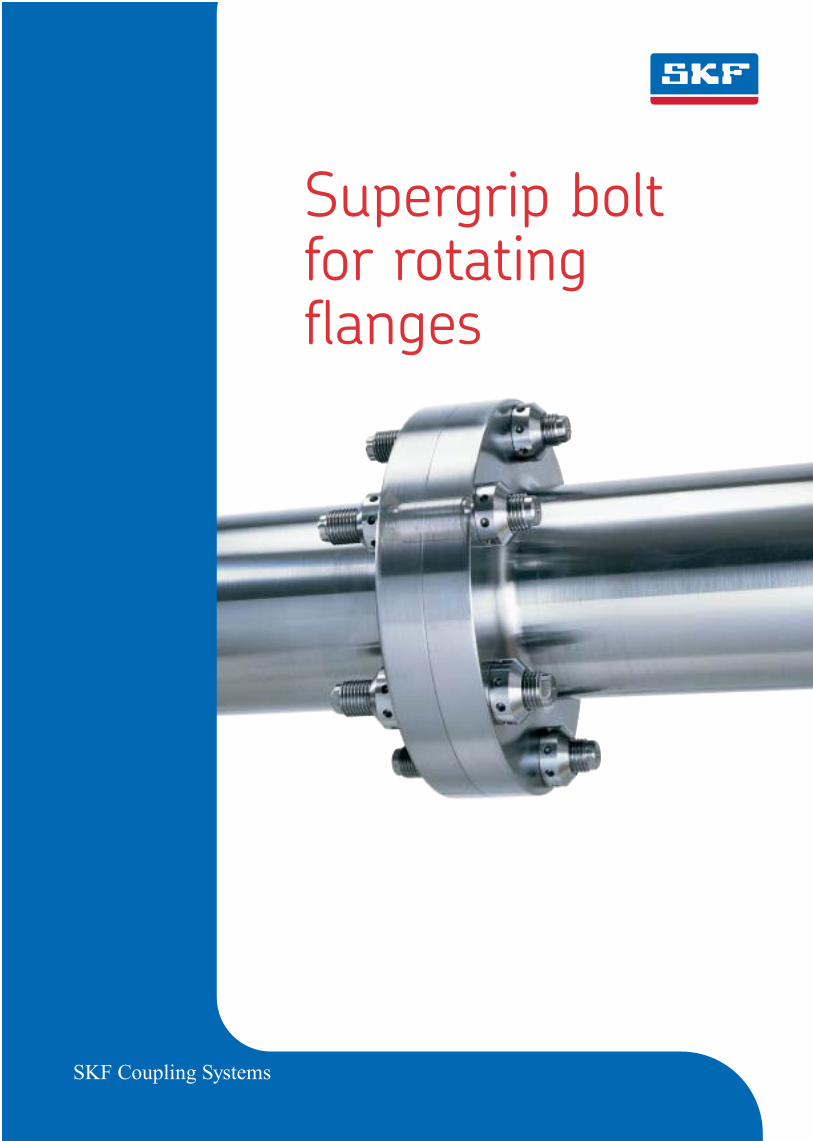
Cut down on downtime!
At a time when maintenance cost efficiency inheavy industries is a make-or-break factor inoperational economy, the time-saving Supergripconcept can cut costs dramatically.
When you connect your couplings withSupergrip bolts, there is no uncertainty aboutthe length of downtime for removing the bolts.No worry about whether the bolts have jammedor seized in the holes. You know that once thetension and expansion pressure has beenreleased, each bolt will slide out as easily as it went in.
In the marine industry couplings have to bedisassembled periodically for surveys. Shipsequipped with Supergrip bolts have consistentlycut the time to remove and remount propellershaft coupling bolts.
Steam turbine couplings have to be separatedat certain intervals for overhaul, inspection andlevelling. A study released by the Swedish StatePower Board on the comparison of individuallyfitted bolts with Supergrip bolts showed a 90-percent reduction in the time required to dis-assemble and reassemble the couplings of twoturbo sets (eight couplings).
The unit equipped with Supergrip bolts wasreconnected to the power grid 48 hours earlierthan the unit with conventional bolts. Totalsavings was 19,200,000 KWh (48 hours x 400 MW).
The potential savings with Supergrip boltsover the lifetime of a ship or power station arevery substantial, when translated into profits.
3
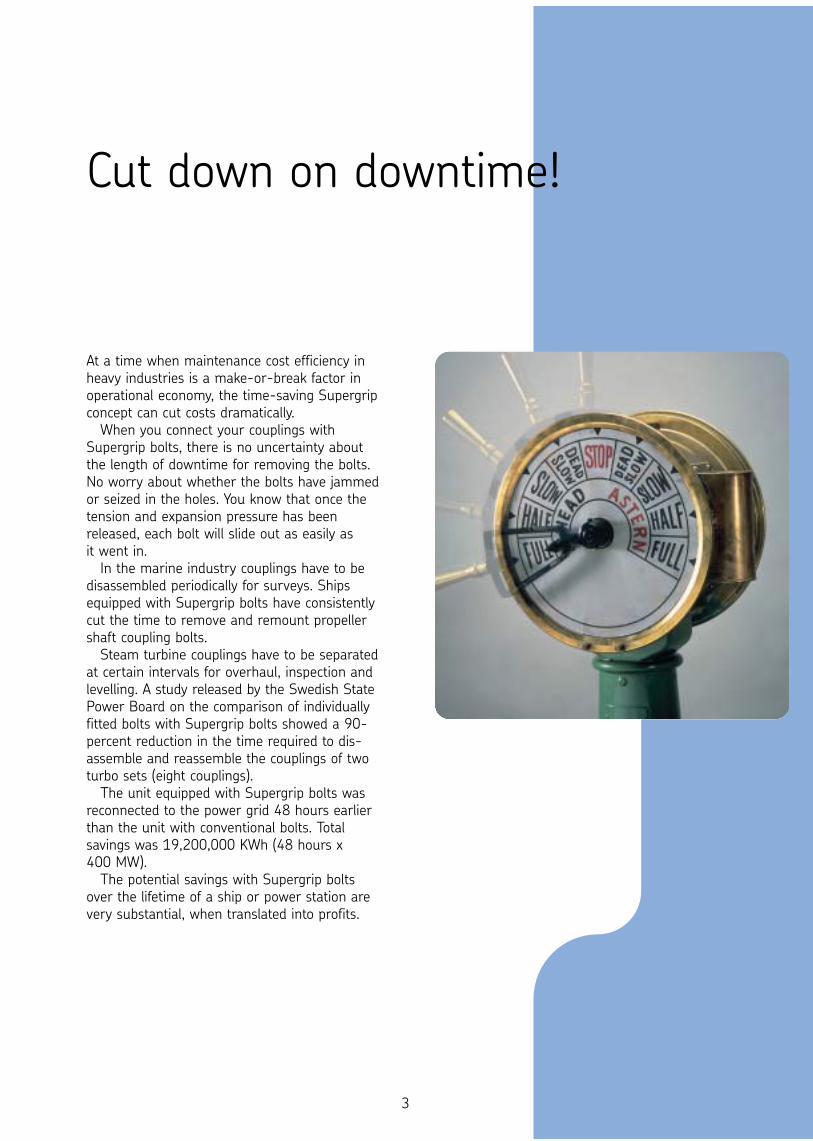
New technology meets an old challenge
Struggling with conventional bolts Prior to the introduction of the Supergrip bolt,mounting and dismounting of large rotatingflange couplings connected with fitted bolts was a poor economical and technical solution.
Fitted bolts that have to be "mauled" into placewith a sledge hammer - after time-consuminghoning of the holes and individual grinding of thebolts - can hardly be termed high technology.
Even with the most qualified bolt fitters, it is hard to achieve an interference fit. In mostcases, there will be a small gap, and after acertain time in service the clearance may
increase, resulting in high bolt stressesand vibrations.
No matter what the application, some time in the future, you will beright back where you started. Each of
the bolts will have to be removed. Andthe job will be further complicated bytrying to drive or bore out conventionalbolts that have seized in the hole dueto fretting, overstressing or too tight to fit.
The Supergrip Bolt offer a better solution forconnecting rotating flange couplings. Comparedwith traditional bolt systems, Supergrip bolts areeasier to install and remove, take much less timeand hold the coupling halves together muchmore securely.
The torque in a coupling connected withSupergrip bolts is transmitted in two ways: bythe shear strength of the expanded bolt in thehole, and by the friction effect at the flange facescreated by pre-loading the bolt. Both effects arecontrolled and measurable.
4
Designed specifically for such high-torqueapplications as propeller shafts, rudderassemblies, turbo generators, rolling mills andsimilar applications, the Supergrip bolt offerssignificant advantages:
Simplified machining of the holes and nogrinding of the bolts. You eliminate re-reamingand rehoning. The bolts are designed to be inserted and removed with an initial clearancefit. There is no risk of seizure.
Easy to install and remove. Compared with conventional systems, you can drastically cut the time required for installing and replacing bolts.
Expansion and pre-load set to predetermined levels. Coupling slippage is eliminated due to the powerful inter- ference fit and high axial pre-load.
Simplified shaft alignment. Controlled and gradual bolt expansion ensures thatconcentricity between the flanges is quickly restored.
Fully interchangeable and can be used repeatedly. No need for a set of spare bolts.
Additional savings at the design stage Due to the uniform torque transmissionbetween the bolts, combined with thefriction force created between the flanges, the number and/or diameter of the bolts in the coupling can be reduced,while still retaining a good safety margin.
By reducing the bolt diameter, the flangediameter can also be reduced, resulting in morecompact and less expensive coupling flanges.
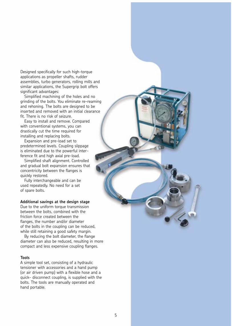
Tools A simple tool set, consisting of a hydraulic tensioner with accessories and a hand pump(or air driven pump) with a flexible hose and aquick- disconnect coupling, is supplied with thebolts. The tools are manually operated and hand portable.
5
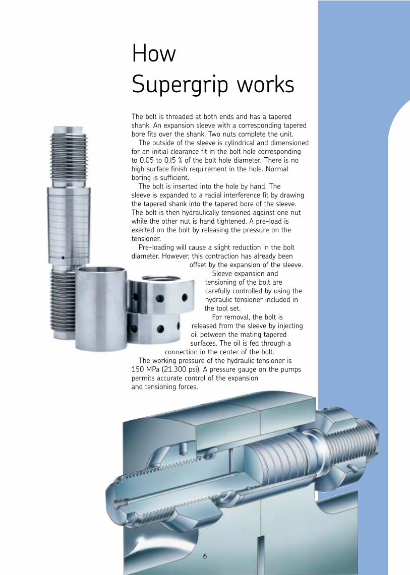
How Supergrip works The bolt is threaded at both ends and has a tapered shank. An expansion sleeve with a corresponding taperedbore fits over the shank. Two nuts complete the unit.
The outside of the sleeve is cylindrical and dimensionedfor an initial clearance fit in the bolt hole correspondingto 0.05 to 0.l5 % of the bolt hole diameter. There is nohigh surface finish requirement in the hole. Normalboring is sufficient.
The bolt is inserted into the hole by hand. The sleeve is expanded to a radial interference fit by drawingthe tapered shank into the tapered bore of the sleeve.The bolt is then hydraulically tensioned against one nutwhile the other nut is hand tightened. A pre-load isexerted on the bolt by releasing the pressure on thetensioner.
Pre-loading will cause a slight reduction in the boltdiameter. However, this contraction has already been
offset by the expansion of the sleeve. Sleeve expansion and
tensioning of the bolt arecarefully controlled by using thehydraulic tensioner included inthe tool set.
For removal, the bolt isreleased from the sleeve by injectingoil between the mating taperedsurfaces. The oil is fed through a
connection in the center of the bolt. The working pressure of the hydraulic tensioner is
150 MPa (21.300 psi). A pressure gauge on the pumpspermits accurate control of the expansion and tensioning forces.
6
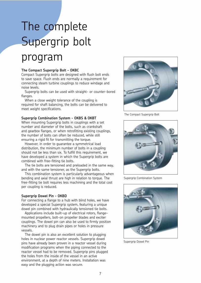
The complete Supergrip boltprogramThe Compact Supergrip Bolt - OKBC Compact Supergrip bolts are designed with flush bolt ends to save space. Flush ends are normally a requirement forconnecting steam turbine couplings to reduce windage andnoise levels.
Supergrip bolts can be used with straight- or counter-boredflanges.
When a close weight tolerance of the coupling is required for shaft balancing, the bolts can be delivered tomeet weight specifications.
Supergrip Combination System - OKBS & OKBT When mounting Supergrip bolts in couplings with a setnumber and diameter of the bolts, such as crankshaft and gearbox flanges, or when retrofitting existing couplings, the number of bolts can often be reduced, while still ensuring a rigid fit for transmitting the torque.
However, in order to guarantee a symmetrical loaddistribution, the minimum number of bolts in a couplingshould not be less than six. To fulfill this requirement, we have developed a system in which the Supergrip bolts arecombined with free-fitting tie bolts.
The tie bolts are tensioned and preloaded in the same way,and with the same tensioner, as the Supergrip bolts.
This combination system is particularly advantageous whenbending and axial thrust are high in relation to torque. Thefree-fitting tie bolt requires less machining and the total costper coupling is reduced.
Supergrip Dowel Pin - OKBDFor connecting a flange to a hub with blind holes, we havedeveloped a special Supergrip system, featuring a uniquedowel pin combined with hydraulically tensioned tie bolts.
Applications include built-up of electrical rotors, flange-mounted propellers, bolt-on propeller blades and excitercouplings. The dowel pin can also be used to firmly positionmachinery and to plug drain pipes or holes in pressurevessels.
The dowel pin is also an excellent solution to plugging holes in nuclear power reactor vessels. Supergrip dowel pins have already been proven in a reactor vessel duringmodification programs when the piping connected to thereactor vessel had to be removed. Supergrip pins plugged the holes from the inside of the vessel in an activeenvironment, at a depth of nine meters. Installation was easy and the plugging action was secure.
The Compact Supergrip Bolt
Supergrip Combination System
Supergrip Dowel Pin
7
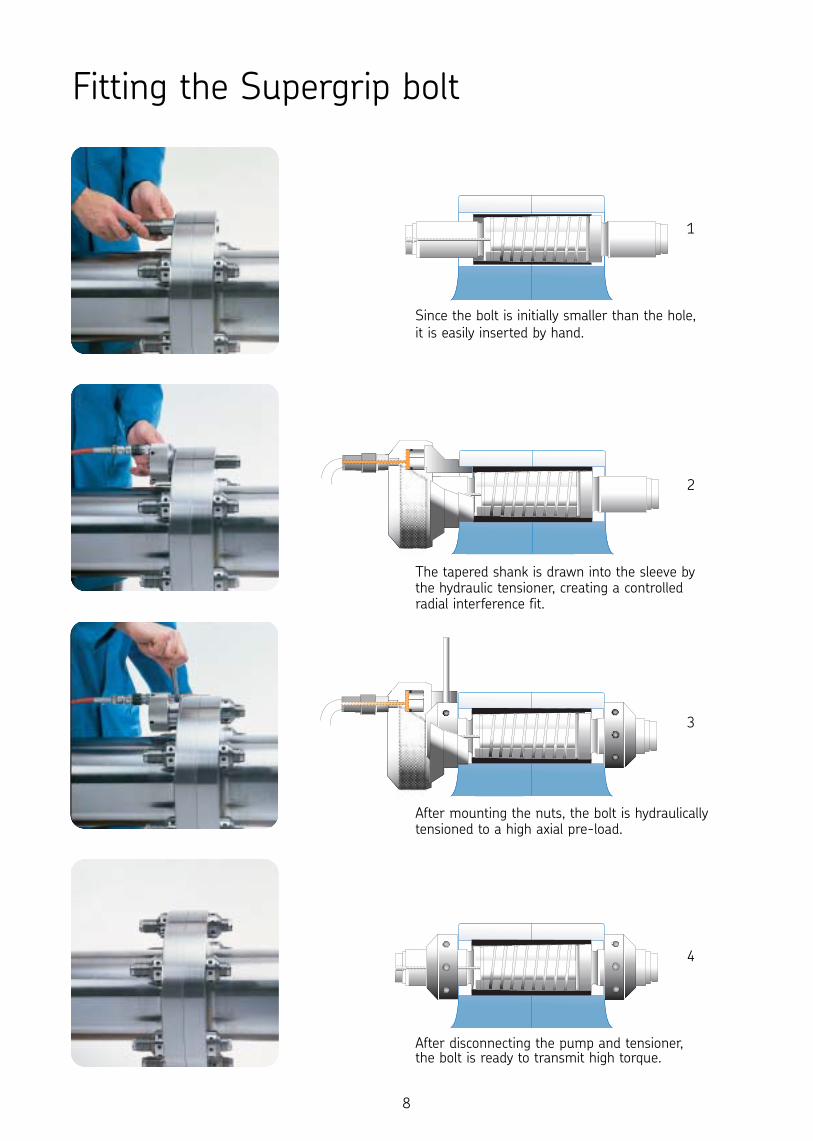
Fitting the Supergrip bolt
Since the bolt is initially smaller than the hole, it is easily inserted by hand.
The tapered shank is drawn into the sleeve bythe hydraulic tensioner, creating a controlledradial interference fit.
After mounting the nuts, the bolt is hydraulicallytensioned to a high axial pre-load.
After disconnecting the pump and tensioner, the bolt is ready to transmit high torque.
1
4
3
2
8
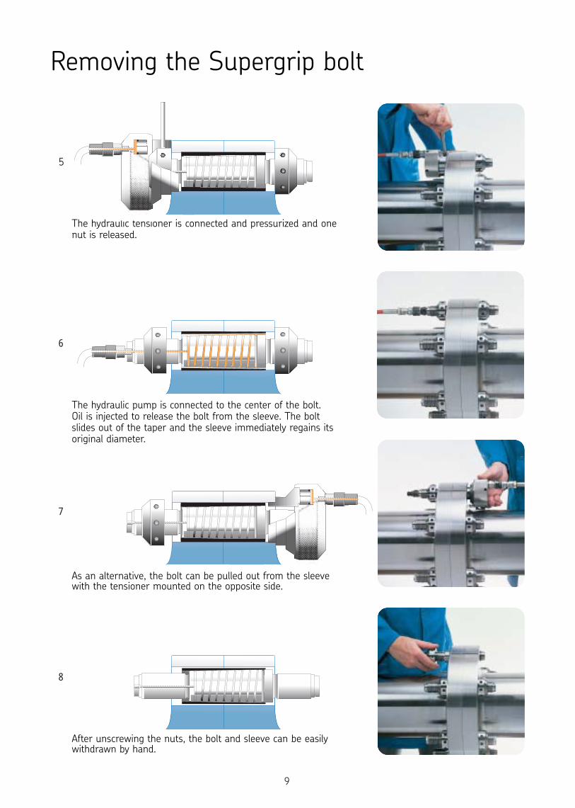
Removing the Supergrip bolt
The hydraulic tensioner is connected and pressurized and onenut is released.
The hydraulic pump is connected to the center of the bolt. Oil is injected to release the bolt from the sleeve. The boltslides out of the taper and the sleeve immediately regains itsoriginal diameter.
As an alternative, the bolt can be pulled out from the sleevewith the tensioner mounted on the opposite side.
After unscrewing the nuts, the bolt and sleeve can be easilywithdrawn by hand.
5
6
7
8
9
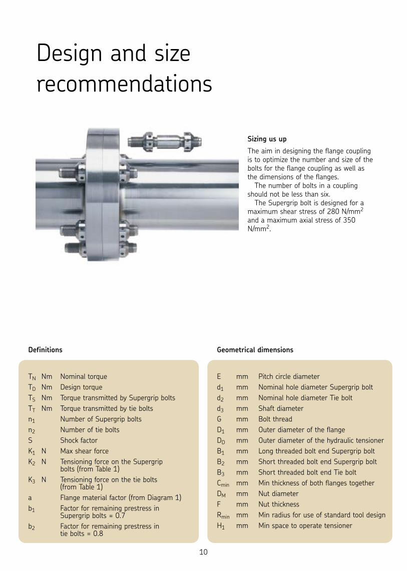
Sizing us up
The aim in designing the flange couplingis to optimize the number and size of thebolts for the flange coupling as well asthe dimensions of the flanges.
The number of bolts in a couplingshould not be less than six.
The Supergrip bolt is designed for amaximum shear stress of 280 N/mm2
and a maximum axial stress of 350N/mm2.
Definitions
TN Nm Nominal torqueTD Nm Design torqueTS Nm Torque transmitted by Supergrip boltsTT Nm Torque transmitted by tie boltsn1 Number of Supergrip boltsn2 Number of tie boltsS Shock factorK1 N Max shear force K2 N Tensioning force on the Supergrip
bolts (from Table 1) K3 N Tensioning force on the tie bolts
(from Table 1)a Flange material factor (from Diagram 1) b1 Factor for remaining prestress in
Supergrip bolts = 0.7b2 Factor for remaining prestress in
tie bolts = 0.8
Design and sizerecommendations
Geometrical dimensions
E mm Pitch circle diameterd1 mm Nominal hole diameter Supergrip boltd2 mm Nominal hole diameter Tie bolt d3 mm Shaft diameterG mm Bolt thread D1 mm Outer diameter of the flangeDD mm Outer diameter of the hydraulic tensioner B1 mm Long threaded bolt end Supergrip bolt B2 mm Short threaded bolt end Supergrip bolt B3 mm Short threaded bolt end Tie bolt Cmin mm Min thickness of both flanges together DM mm Nut diameter F mm Nut thickness Rmin mm Min radius for use of standard tool design H1 mm Min space to operate tensioner
10
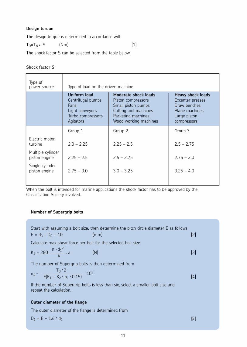
Design torque
The design torque is determined in accordance with
TD=TN • S (Nm) [1]
The shock factor S can be selected from the table below.
Type of power source Type of load on the driven machine
Uniform load Moderate shock loads Heavy shock loadsCentrifugal pumps Piston compressors Excenter pressesFans Small piston pumps Draw benches Light conveyors Cutting tool machines Plane machinesTurbo compressors Packeting machines Large pistonAgitators Wood working machines compressors
Group 1 Group 2 Group 3
Electric motor,turbine 2.0 – 2.25 2.25 – 2.5 2.5 – 2.75
Multiple cylinder piston engine 2.25 – 2.5 2.5 – 2.75 2.75 – 3.0
Single cylinder piston engine 2.75 – 3.0 3.0 – 3.25 3.25 – 4.0
When the bolt is intended for marine applications the shock factor has to be approved by theClassification Society involved.
Number of Supergrip bolts
Start with assuming a bolt size, then determine the pitch circle diameter E as follows E = d3 + DD + 10 (mm) [2]
Calculate max shear force per bolt for the selected bolt size π • d1
2K1 = 280 • a (N) [3]
4
The number of Supergrip bolts is then determined from TD • 2
n1 = 103E(K1 + K2 • b1 • 0.15) [4]
If the number of Supergrip bolts is less than six, select a smaller bolt size and repeat the calculation.
Outer diameter of the flange
The outer diameter of the flange is determined from
D1 = E + 1.6 • d1 [5]
11
Shock factor S
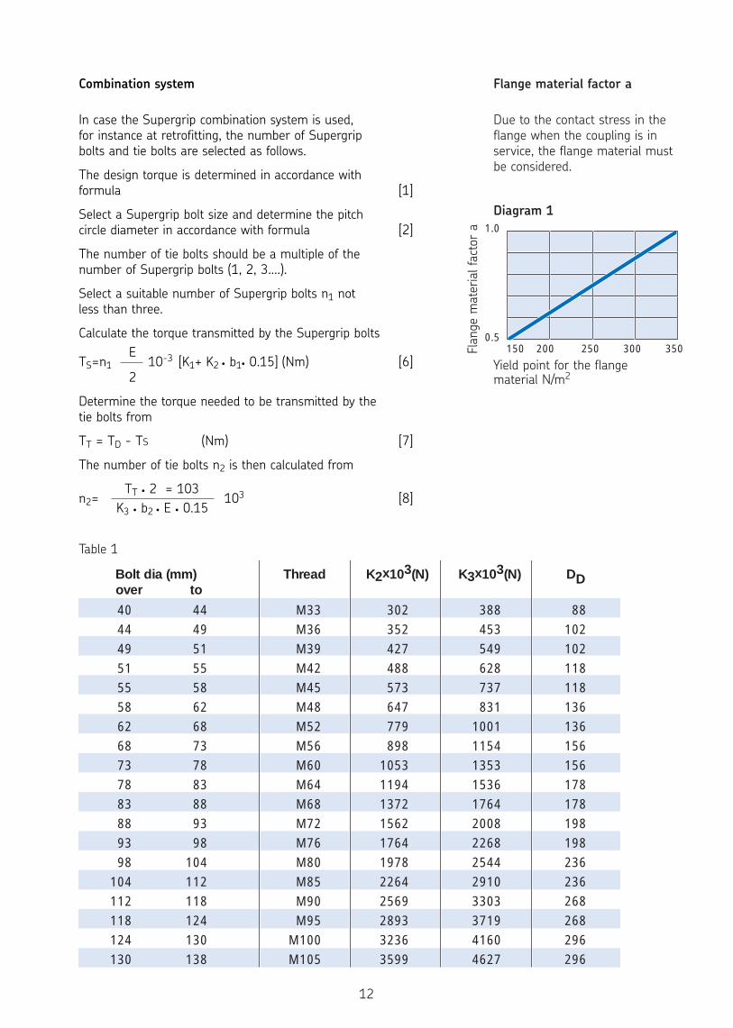
Combination system
In case the Supergrip combination system is used, for instance at retrofitting, the number of Supergrip bolts and tie bolts are selected as follows.
The design torque is determined in accordance with formula [1]
Select a Supergrip bolt size and determine the pitch circle diameter in accordance with formula [2]
The number of tie bolts should be a multiple of the number of Supergrip bolts (1, 2, 3....).
Select a suitable number of Supergrip bolts n1 not less than three.
Calculate the torque transmitted by the Supergrip boltsE
TS=n1 10-3 [K1+ K2 • b1• 0.15] (Nm) [6]2
Determine the torque needed to be transmitted by the tie bolts from
TT = TD - TS (Nm) [7]
The number of tie bolts n2 is then calculated from
TT • 2 = 103 n2= 103 [8]
K3 • b2 • E • 0.15
Bolt dia (mm) Thread K2x103(N) K3x103(N) DD over to
4044495155586268737883889398
104112118124130
44495155586268737883889398
104112118124130138
M33M36M39M42M45M48M52M56M60M64M68M72M76M80M85M90M95
M100M105
302352427488573647779898
10531194137215621764197822642569289332363599
388453549628737831
1001115413531536176420082268254429103303371941604627
88102102118118136136156156178178198198236236268268296296
150 200 250 300 350
1.0
0.5
Flange material factor a
Due to the contact stress in the flange when the coupling is inservice, the flange material must be considered.
Yield point for the flangematerial N/m2
12
Table 1
Diagram 1
Flan
ge m
ater
ial f
acto
r a
Dimensions
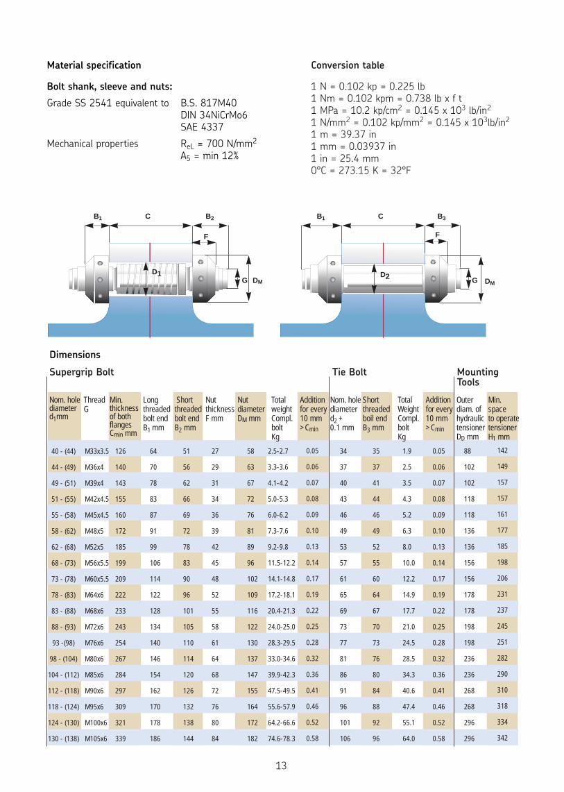
Material specification
Bolt shank, sleeve and nuts:
Grade SS 2541 equivalent to B.S. 817M40 DIN 34NiCrMo6 SAE 4337
Mechanical properties ReL = 700 N/mm2
A5 = min 12%
Nom. holediameterd1mm
ThreadG
Min.thicknessof bothflangesCmin mm
Longthreadedbolt endB1 mm
Shortthreadedbolt endB2 mm
NutthicknessF mm
Nutdiameter DM mm
TotalweightCompl.boltKg
Additionfor every10 mm>Cmin
Nom. holediameterd2 + 0.1 mm
Shortthreadedboil endB3 mm
TotalWeightCompl.boltKg
Additionfor every10 mm>Cmin
Outerdiam. ofhydraulictensionerDD mm
Min.spaceto operatetensionerH1 mm
40 - (44)
44 - (49)
49 - (51)
51 - (55)
55 - (58)
58 - (62)
62 - (68)
68 - (73)
73 - (78)
78 - (83)
83 - (88)
88 - (93)
93 -(98)
98 - (104)
104 - (112)
112 - (118)
118 - (124)
124 - (130)
130 - (138)
M33x3.5
M36x4
M39x4
M42x4.5
M45x4.5
M48x5
M52x5
M56x5.5
M60x5.5
M64x6
M68x6
M72x6
M76x6
M80x6
M85x6
M90x6
M95x6
M100x6
M105x6
126
140
143
155
160
172
185
199
209
222
233
243
254
267
284
297
309
321
339
64
70
78
83
87
91
99
106
114
122
128
134
140
146
154
162
170
178
186
51
56
62
66
69
72
78
83
90
96
101
105
110
114
120
126
132
138
144
27
29
31
34
36
39
42
45
48
52
55
58
61
64
68
72
76
80
84
58
63
67
72
76
81
89
96
102
109
116
122
130
137
147
155
164
172
182
2.5-2.7
3.3-3.6
4.1-4.2
5.0-5.3
6.0-6.2
7.3-7.6
9.2-9.8
11.5-12.2
14.1-14.8
17.2-18.1
20.4-21.3
24.0-25.0
28.3-29.5
33.0-34.6
39.9-42.3
47.5-49.5
55.6-57.9
64.2-66.6
74.6-78.3
0.05
0.06
0.07
0.08
0.09
0.10
0.13
0.14
0.17
0.19
0.22
0.25
0.28
0.32
0.36
0.41
0.46
0.52
0.58
34
37
40
43
46
49
53
57
61
65
69
73
77
81
86
91
96
101
106
35
37
41
44
46
49
52
55
60
64
67
70
73
76
80
84
88
92
96
1.9
2.5
3.5
4.3
5.2
6.3
8.0
10.0
12.2
14.9
17.7
21.0
24.5
28.5
34.3
40.6
47.4
55.1
64.0
0.05
0.06
0.07
0.08
0.09
0.10
0.13
0.14
0.17
0.19
0.22
0.25
0.28
0.32
0.36
0.41
0.46
0.52
0.58
88
102
102
118
118
136
136
156
156
178
178
198
198
236
236
268
268
296
296
142
149
157
157
161
177
185
198
206
231
237
245
251
282
290
310
318
334
342
Conversion table
1 N = 0.102 kp = 0.225 lb 1 Nm = 0.102 kpm = 0.738 lb x f t 1 MPa = 10.2 kp/cm2 = 0.145 x 10³ lb/in2
1 N/mm2 = 0.102 kp/mm2 = 0.145 x 10³lb/in2
1 m = 39.37 in 1 mm = 0.03937 in 1 in = 25.4 mm 0°C = 273.15 K = 32°F
Supergrip Bolt Tie Bolt Mounting Tools
D1 D2DM
B2 B3C C
F F
G
B1 B1
DMG
13
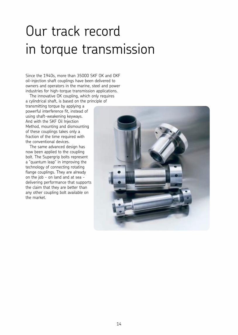
Since the 1940s, more than 35000 SKF OK and OKFoil-injection shaft couplings have been delivered toowners and operators in the marine, steel and powerindustries for high-torque transmission applications.
The innovative OK coupling, which only requires a cylindrical shaft, is based on the principle oftransmitting torque by applying apowerful interference fit, instead ofusing shaft-weakening keyways. And with the SKF Oil InjectionMethod, mounting and dismountingof these couplings takes only afraction of the time required with the conventional devices.
The same advanced design hasnow been applied to the coupling bolt. The Supergrip bolts represent a "quantum leap" in improving thetechnology of connecting rotatingflange couplings. They are already on the job - on land and at sea -delivering performance that supportsthe claim that they are better thanany other coupling bolt available onthe market.
Our track record in torque transmission
14
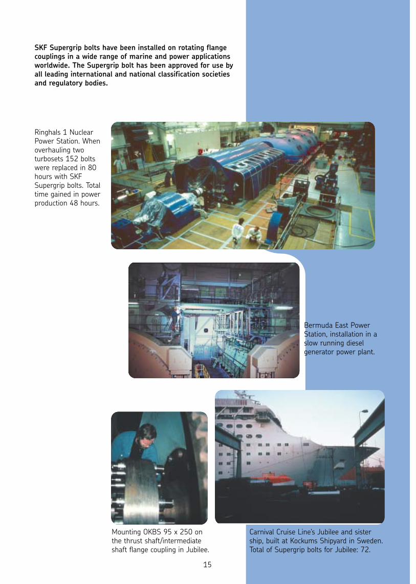
SKF Supergrip bolts have been installed on rotating flangecouplings in a wide range of marine and power applicationsworldwide. The Supergrip bolt has been approved for use byall leading international and national classification societiesand regulatory bodies.
Ringhals 1 NuclearPower Station. Whenoverhauling twoturbosets 152 boltswere replaced in 80hours with SKFSupergrip bolts. Totaltime gained in powerproduction 48 hours.
Mounting OKBS 95 x 250 onthe thrust shaft/intermediateshaft flange coupling in Jubilee.
Carnival Cruise Line's Jubilee and sistership, built at Kockums Shipyard in Sweden.Total of Supergrip bolts for Jubilee: 72.
Bermuda East PowerStation, installation in aslow running dieselgenerator power plant.
15
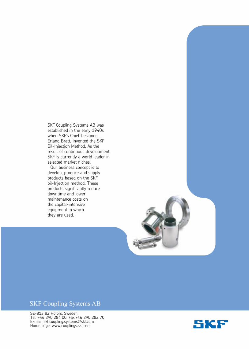
SE-813 82 Hofors, Sweden. Tel: +46 290 284 00. Fax:+46 290 282 70E-mail: [email protected] page: www.couplings.skf.com
SKF Coupling Systems AB wasestablished in the early 1940swhen SKF’s Chief Designer, Erland Bratt, invented the SKFOil-Injection Method. As theresult of continuous development,SKF is currently a world leader inselected market niches.
Our business concept is todevelop, produce and supplyproducts based on the SKF oil-Injection method. Theseproducts significantly reducedowntime and lower maintenance costs on the capital-intensive equipment in which they are used.