Superconducting magnetsfor fusion - Robert B. Laughlin
11
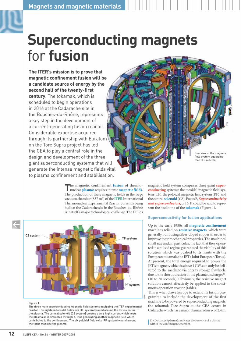
CLEFS CEA - No. 56 - WINTER 2007-2008 12 Magnets and magnetic materials The ITER's mission is to prove that magnetic confinement fusion will be a candidate source of energy by the second half of the twenty-first century. The tokamak, which is scheduled to begin operations in 2016 at the Cadarache site in the Bouches-du-Rhône, represents a key step in the development of a current-generating fusion reactor. Considerable expertise acquired through its partnership with Euratom on the Tore Supra project has led the CEA to play a central role in the design and development of the three giant superconducting systems that will generate the intense magnetic fields vital to plasma confinement and stabilisation. Superconducting magnets for fusion ITER ITER T he magnetic confinement fusion of thermo- nuclear plasmas requires intense magnetic fields. The production of these magnetic fields in the large vacuum chamber (837 m 3 ) of the ITER International Thermonuclear Experimental Reactor, currently being built at the Cadarache site in the Bouches-du-Rhône is in itself a major technological challenge. The ITER's (1) Discharge (plasma): indicates the presence of a plasma within the confinement chamber. Figure 1. The three main superconducting magnetic field systems equipping the ITER experimental reactor. The eighteen toroidal field coils (TF system) wound around the torus confine the plasma. The central solenoid (CS system) creates a very high current which heats the plasma as it circulates through it, thus generating another magnetic field which contributes to the confinement. The six poloidal field coils (PF system) wound around the torus stabilise the plasma. TF system PF system CS system magnetic field system comprises three giant super- conducting systems: the toroidal magnetic field sys- tem (TF), the poloidal magnetic field system (PF), and the central solenoid (CS); Focus B, Superconductivity and superconductors, p. 16. It could be said to repre- sent the backbone of the tokamak (Figure 1). Superconductivity for fusion applications Up to the early 1980s, all magnetic confinement machines relied on resistive magnets, which were generally built using silver-doped copper in order to improve their mechanical properties. The machines' small size and, in particular, the fact that they opera- ted in a pulsed regime guaranteed the viability of this solution which was pushed to its limits with the European tokamak, the JET (Joint European Torus). At present, the total energy required to power the JET's magnets, which is above 1 GW, can only be deli- vered to the machine via energy storage flywheels, due to the short duration of the plasma discharges (1) (10 to 30 seconds). Obviously, the resistive magnet solution cannot effectively be applied to the conti- nuous operation reactor (table). This is what drove Europe to extend its fusion pro- gramme to include the development of the first machine to be powered by superconducting magnets: the tokamak Tore Supra at the CEA centre in Cadarache which has a major plasma radius R of 2.4 m. Overview of the magnetic field system equipping the ITER reactor.
Transcript of Superconducting magnetsfor fusion - Robert B. Laughlin
CLEFS CEA - No. 56 - WINTER 2007-200812
Magnets and magnetic materials
The ITER's mission is to prove thatmagnetic confinement fusion will be a candidate source of energy by thesecond half of the twenty-firstcentury. The tokamak, which isscheduled to begin operations in 2016 at the Cadarache site in the Bouches-du-Rhône, representsa key step in the development of a current-generating fusion reactor.Considerable expertise acquiredthrough its partnership with Euratomon the Tore Supra project has led the CEA to play a central role in thedesign and development of the threegiant superconducting systems that willgenerate the intense magnetic fields vitalto plasma confinement and stabilisation.
Superconducting magnetsfor fusion
ITER
ITER
The magnetic confinement fusion of thermo-nuclear plasmas requires intense magnetic fields.
The production of these magnetic fields in the largevacuum chamber (837 m3) of the ITER InternationalThermonuclear Experimental Reactor, currently beingbuilt at the Cadarache site in the Bouches-du-Rhôneis in itself a major technological challenge. The ITER's
(1) Discharge (plasma): indicates the presence of a plasmawithin the confinement chamber.
Figure 1. The three main superconducting magnetic field systems equipping the ITER experimentalreactor. The eighteen toroidal field coils (TF system) wound around the torus confine the plasma. The central solenoid (CS system) creates a very high current which heats the plasma as it circulates through it, thus generating another magnetic field whichcontributes to the confinement. The six poloidal field coils (PF system) wound around the torus stabilise the plasma.
TF system
PF system
CS system
magnetic field system comprises three giant super-conducting systems: the toroidal magnetic field sys-tem (TF), the poloidal magnetic field system (PF), andthe central solenoid (CS); Focus B, Superconductivityand superconductors, p. 16. It could be said to repre-sent the backbone of the tokamak (Figure 1).
Superconductivity for fusion applications
Up to the early 1980s, all magnetic confinementmachines relied on resistive magnets, which weregenerally built using silver-doped copper in order toimprove their mechanical properties. The machines'small size and, in particular, the fact that they opera-ted in a pulsed regime guaranteed the viability of thissolution which was pushed to its limits with theEuropean tokamak, the JET (Joint European Torus).At present, the total energy required to power theJET's magnets, which is above 1 GW, can only be deli-vered to the machine via energy storage flywheels,due to the short duration of the plasma discharges(1)
(10 to 30 seconds). Obviously, the resistive magnetsolution cannot effectively be applied to the conti-nuous operation reactor (table). This is what drove Europe to extend its fusion pro-gramme to include the development of the firstmachine to be powered by superconducting magnets:the tokamak Tore Supra at the CEA centre inCadarache which has a major plasma radius R of 2.4 m.
Overview of the magneticfield system equipping the ITER reactor.

CLEFS CEA - No. 56 - WINTER 2007-2008 13
The Tore Supra's TF system contains 40 tons of super-conducting materials (Figure 2). The machine hasbeen producing plasmas since 1988, thus followingon from the extra-small TRIAM tokamak developedin 1986 in Japan, which has a major plasma radiusR of 0.8 m. The outstanding operating performanceof the Tore Supra superconducting system over a pe -riod of years paved the way for introducing the novelmagnetic confinement technology vital to the suc-cess of fusion programmes.Today's large-scale magnetic confinement fusion pro-jects no longer use resistive magnets, which have beensystematically replaced by superconducting coils. TheLHD torsatron(2), built in Japan to similar dimen-sions as those of the Tore Supra, started plasma pro-duction in 1998, followed by the Chinese-developedEAST tokamak in 2006. Several machines are cur-rently under construction worldwide. The most impor-tant are the stellarator(2) W7-X (Germany) and thethree tokamaks: KSTAR (South Korea), SST1 (India)and JT-60SA (Japan). Rounding up the field is theITER which still operates on a pulsed regime and isa fully superconducting tokamak. Quite apart fromthe problems of yield and electric consumption, thereis not one single electricity network in the world thatcan viably supply the 2 GW power input that wouldbe required by a resistive machine for a 500-secondplasma discharge.However, with the DEMO, a current-generating fusionreactor supplying 1,000 MW of electrical power whichis scheduled to enter the construction phase in twentyyears time, the electricity needed to power the super-conducting magnet cryogenics system would lie withina range of 20 to 30 MW.Research into thermonuclear fusion and applied super-conductivity has only recently intersected. Until the1980s, research into applied superconductivity was clo-sely linked to the fields of medical imaging and high-energy nuclear physics which were instrumental in driving major breakthroughs in this domain. This initialresearch underpinned the construction of the firstsuperconducting fusion machines; a good example isthe development of the niobium-titanium alloy (NbTi)which has since amply demonstrated its worth. Wherefusion applications are concerned though, the size ofthe machines, the intensity of the magnetic fields, andtheir specific magnetic field variability characteristics,mean the field of applied superconducting has to facea whole new set of requirements.
(2) Torsatron and stellarator: the torsatron is a magneticconfinement system in which the toroidal and poloidal fieldlines confining the plasma are generated by magnets spirallingaround the vacuum chamber. This is a simplified version ofthe stellarator, which has two magnet systems.
The R&D programmes tasked to the ITER over thelast ten years have seen the industrialisation of a novelsuperconducting material, niobium-tin (Nb3Sn). Theconstruction of two superconducting coil prototy-pes for the ITER programme, and their subsequenttesting at facilities in both Europe and Japan (2000-2002) were used to check the validity of the designchoices made for the ITER coils. The ITER magneticsystem and its associated cryogenic refrigerator alonerepresent nearly a third (31%) of the machine's cost,which gives an indication of how pivotal these deve-lopments are.
The superconducting cables for the ITER
The concept behind the superconducting cable- in-conduit conductor (CICC) derives from the ap -plication of high-current electrical engineering
Table.The electric powers required (for the toroidal field system only) for some of the magnetic confinement fusion projects using copper magnet technology.
Figure 2. Sketch of a superconducting coil used in the Tore Supra TF system, illustrating the 26 double-pancake coils shown in their double-casing system.
machine major radius plasma magnetic field on fusion electric power(discharge time) (m) volume (m3) plasma axis (T) power (MW) (MW)
Tore Supra 2.4 24 4.5 0 � 150 (machine with (1,000 s) superconducting magnet technology)
JET Upgrade 2.96 100 4 � 20 � 500 (machine with (10 s) copper magnet technology)ITER 6.2 837 5.3 � 400 � 800 (machine with
(500 s) superconducting magnet technology)
CEA
thick casing
channels(4.5 K)
polyimid-alumina
chocks
thincasing(1.8 K)
groundinsulation
glass-epoxychock
glassperforatedspacingplates
superconductor
CLEFS CEA - No. 56 - WINTER 2007-200814
Magnets and magnetic materials
technologies to the cryoelectricity domain, particu-larly conductors cooled via hydrogen and the watersupplying the rotors and stators on the large turbinegenerators found in power plants.In fact, the ITER's magnetic systems, in particular theTF system, store unprecedented amounts of energy,far outpacing all the other superconducting systemsdeveloped to date. The huge size of these magneticsystems means it is essential to use high currents (40 to70 kA) to limit inductances and, therefore, electricvoltages, during operation. Another feature specificto the ITER's magnetic systems is the rapid field andcurrent changes affecting the PF and CS systems.Medical imaging coils, for example, operate underconstant current, meaning that electric voltages remainvery high (5 to 10 kV with respect to ground). Thecable has a steel sheath that enables it to mechani-cally withstand large electromagnetic stresses at closerange, without allowing them to accumulate in thesuperconducting material. The sheath is itself insu-lated by a glass and Kapton®(3) multilayer material.The helium circulating through the cable preventsexcessive heating due to losses associated with resi-dual neutron radiation and field and current fluc-tuations. In addition, the conductor equipping ITER coilshas to be able to withstand a major event, i.e. dis-ruption(4) of the 15 MA plasma, without losing itssuperconducting state. Such a disruption wouldtrigger a rapid field variation on the conductors.This operating constraint can only be achieved viathe typical CICC structure: a fine subdivision intostrands wetted by helium at a high specific heat.This concept, invented in 1975, lends the CICC
exceptional stability in relation to the thermal dis-ruptions characterising tokamak magnetic systemenvironments.Finally, the shape of the conductor gives the coil itsspecific quench-related characteristics, i.e. rapid lossof its superconducting state, an event that should notarise in theory but which cannot be wholly discoun-ted in practice. Unlike bath cooled coils, quench propagation is channelled through the conduit andtriggers a rise in pressure. Engineers working on themodelling and detection of quench in tokamak coilswith the aim of protecting them via the extraction ofenergy are faced with a number of specific problems,mainly stemming from the fact that they so far havelittle experience to draw on regarding how tokamakcoils respond to quench.There have been several key breakthroughs in conduc-tor technology, even though there are still some elec-tromechanical hitches with Nb3Sn conductors forexample. CICCs have to meet fusion specificationsand be simple to industrialise.ITER-type CICCs contain around a thousand twis-ted strands (Figure 3) in a five stage cable which isinserted into a strong steel sheath that guarantees itsleaktightness. Figure 4 illustrates two typical conduc-tors, from two samples representing ITER modelcoils. The CICCs used in these model coils exhibitcertain shared characteristics. Six petal-format sub-bundles, made up of twisted strands, are cabledaround a central metal spiral with an internal dia-meter of about 10 mm and a thickness of 1 mm. Inthis CICC concept pioneered by the CEA, a double-hydraulic channel allows helium to circulate throughboth the central area and the area housing the strands,with only a limited pressure drop. The void fractionis about 30%, and is a compromise between severaldifferent aspects of scale (hydraulic, electric andmechanical). The cable's circular shape provides adecisive advantage in terms of manufacture and per-formance. It enables the cable and the sheath to bemanufactured separately, while the cable can be inser-ted into the sheath with a minimum amount of playof only one millimetre. Current distribution in asuperconducting cable in unsteady state is control-
(3) Kapton: polymer film with the feature of being able tomaintain its stability within a very broad temperature rangefrom − 269 °C to 400 °C.
(4) Disruption (plasma disruption): indicates full loss ofplasma confinement. A disruption may have manyconsequences. Any sudden decrease in current and/ormagnetic field induces mirror currents and/or magnetic fieldsin the components surrounding the machine. Thesecomponents are then subjected to what may be considerableforces.
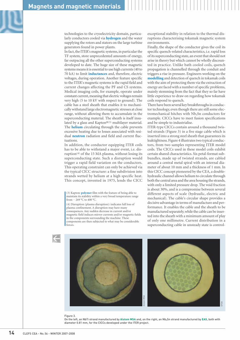
Figure 3. On the left, an NbTi strand manufactured by Alstom MSA and, on the right, an Nb3Sn strand manufactured by EAS, both withdiameter 0.81 mm, for the CICCs developed under the ITER project.
EFD
A
Als
tom
MSA
CLEFS CEA - No. 56 - WINTER 2007-2008 15
led by strand inductance. The circular shape ensu-res inductances are as uniform as possible, althoughnot perfect.
Future directions for superconductingmagnet research
Current research into the technological applicationsof superconductivity to magnets is being driven bythe huge effort involved in the development and cons-truction of the LHC at the CERN (see Superconductingmagnets for the LHC, p. 4), in the ITER project beingrolled out at CEA-Cadarache and the NeuroSpin pro-ject at CEA-Saclay (see Ultra-high-field magnetic reso-nance imaging, p. 30).These projects are all based on the use of very lowtemperatures in the range of 1.8 to 5 K. At the timeof their discovery, it was thought that high-critical-temperature superconductors would herald the emer-gence of a cryogenics technology operating at thetemperature of liquid nitrogen (77 K) that could beapplied to electrical networks. In practice, althoughpromising prototypes for engines and power cableshave been built, at present they can only compete withcopper conductors on certain highly specific mar-kets. From this standpoint, researchers are still at thestage of producing demonstrators.In contrast, there is enormous potential in applyingsuperconductivity technology to the fabrication ofhigh-magnetic-field magnets. These magnets formthe core components for instruments used in manydifferent research domains, such as nuclear physics,particle physics, condensed matter physics, the lifesciences, magnetic confinement fusion, and still others.One common factor spanning all these domains isresearch into the development of high-performancemagnetic systems characterised by high fields andcurrent densities. The number of Nobel Prizes awar-ded to physicists working in this domain over the last
twenty years is ample proof of its importance. NMRspectroscopy, in particular, stresses the necessity ofhaving access to intense, stable and uniform mag -netic fields at over 20 T. In this instance, high-criti-cal-temperature superconducting materials, such asBi2212 or YBaCuO used at low temperature, can pro-vide a means of achieving this target due to their veryhigh critical field.This challenge is spawning remarkable technologicalbreakthroughs with the first prototypes just startingto make their appearance.This would indicate that there are still very promi-sing avenues for future applications of supercon-ducting magnets. As with the medical imaging domain,they will most probably emerge in tandem with theadvances being made in other disciplines. Researchactivities should take this decisive convergence fac-tor into account and be organized accordingly.
> Jean-Luc Duchateau Institute for Magnetic
Confinement Fusion ResearchPhysical Sciences Division
Euratom-CEA Association Cadarache Centre
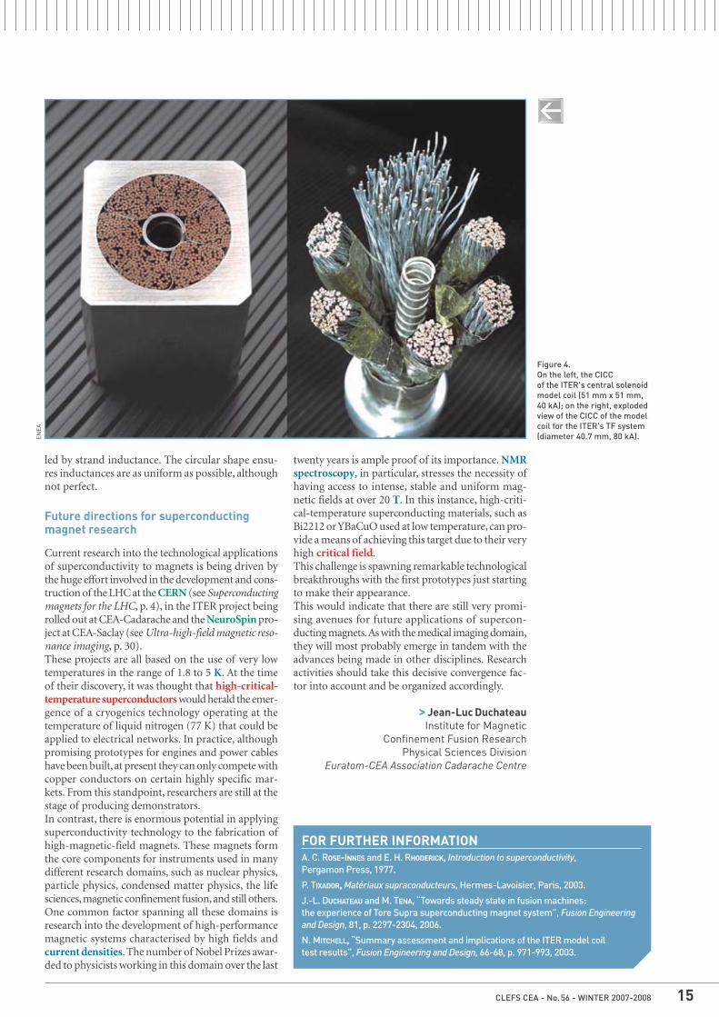
Figure 4.On the left, the CICC of the ITER's central solenoidmodel coil (51 mm x 51 mm,40 kA); on the right, explodedview of the CICC of the modelcoil for the ITER's TF system(diameter 40.7 mm, 80 kA).EN
EA
FOR FURTHER INFORMATIONA. C. ROSE-INNES and E. H. RHODERICK, Introduction to superconductivity, Pergamon Press, 1977.
P. TIXADOR, Matériaux supraconducteurs, Hermes-Lavoisier, Paris, 2003.
J.-L. DUCHATEAU and M. TENA, “Towards steady state in fusion machines: the experience of Tore Supra superconducting magnet system”, Fusion Engineeringand Design, 81, p. 2297-2304, 2006.
N. MITCHELL, “Summary assessment and implications of the ITER model coil test results”, Fusion Engineering and Design, 66-68, p. 971-993, 2003.

Medical imaging is a unique, non-invasiveset of techniques that make it possible tovisualise biological processes actuallywithin living organisms themselves. It isa key means for providing insight intophysiology and pathology, and ultimatelyfor disease diagnosis, prognosis and the-rapy. Imaging is therefore the first-choiceinvestigative tool in several branches ofmedicine and biology.Medical imaging started with X-ray radia-tion and then developed further with thediscovery of artificial radioactivity and theallied screening techniques. The nextleaps forward, first to Nuclear Magnetic
Resonance (NMR) and then to supercon-ducting magnets, led to technologicalbreakthroughs in Magnetic ResonanceImaging (MRI).One of the key dynamic human brain ima-ging methods is Electroencephalography(EEG) which uses electrodes fitted on thescalp to measure the electrical activityproduced by the brain through synapticcurrents generated in neurons. EEG givesinformation on the time-locked neuro-physiological activity of the brain, and inparticular the cerebral cortex. This infor-mation is used in neurology for diagnostics,or in cognitive neuroscience for research.
Magnetoencephalography (MEG) recordsthe magnetic fields produced by the cur-rents generated by neurons in the brain,using sensors fitted close to the head.MEG is employed in clinical settings byneurologists, especially when the focus ison epilepsy, and for cognitive neuroscienceresearch. MEG can also be used to studydevelopmental disorders like dyslexia,psychiatric disorders like schizophreniaand neurodegenerative disorders likeParkinson's and Alzheimer's.Positron Emission Tomography (PET)consists in intravenously administering atracer molecule labelled with a radioac-tive isotope and using external detectiontechniques to track how a normal or dis-eased organ functions. Radioactive tra-cers present the same physico-chemicalproperties as their non-radioactive coun-terparts, with the exception that they areable to emit radiation. This means thatthey act as a marker that is followed, usingappropriate detection methods, to trackthe previously-labelled molecule’s kine-tics through the body. The data gatheredis then analysed and transformed usinga mathematical model to generate ascreen image showing where the radio-tracer settles in the body. PET is a wide -spread technique in physiological orpathophysiological studies on cognitionand behaviour and is commonly used tostudy central nervous system disorders
The main methods of medical imagingCFOCUS
A PET image. The PET camera detects the positrons emitted by radioactive tracers previously injected into the living subject, and 3D images of the target organ are reconstructed by computer analysis.
P. S
trop
pa/C
EA
SHFJ
/CEA
Melancholic depression. PET imagesmeasuring regional energy activities mergedwith the aMRI image of the patient's brain.Areas of hypoactivation are individuallydetected.
such as epilepsy, cerebral ischaemia,stroke, and neurodegenerative disorders(Parkinson's disease, Huntington's dis-ease).Magnetic Resonance Imaging (MRI) is anon-invasive in vivo imaging method. MRIis capable of studying 'soft' tissue such asthe brain, bone marrow, or muscle, forexample. It can be used to map anatomicstructure (anatomical MRI, or aMRI), moni-tor organ function (functional MRI, fMRI)and track various processes of metabolism(Magnetic Reso nance Spectroscopy, MRS).After its first developments in 1946, MRIuses the physical phenomenon of NMR thatexploits the magnetic properties of atomicnuclei. Certain nuclei, such as the hydro-gen nuclei for example, have a weak mag -netic moment, or spin. NMR works bydetecting variations in the magnetisationof atomic nuclei in response to an extre-mely powerful magnetic field and electro-magnetic wave-driven excitation. When anelectromagnetic wave is applied at the rightfrequency, i.e. the resonance frequency,
these nuclei change alignment and emitsignals as they return to their initial posi-tion. Technological advances in computingand magnetic fields have taken NMR fromcondensed matter physics on to chemicalanalysis and then structural biology, andmore recently into medical ima-ging.Anatomical MRI. MRI makesit possible to visuallydisplay all body organs.The resonance, under avery-high magneticfield, of water molecu-les, which are naturallyabundant in most bio-logical tissues, is usedto generate cross-sec-tional images detailingbrain structures (greymatter, white matter) downto the millimetre and evenless. Radiologists use 'ana-tomical' imaging to detectand localize brain lesions.
Functional MRI. The recent acceleration indata acquisition and processing has led tothe advent of ‘functional’ MRI, which is ableto show neural activity in different brainregions. Indeed, speaking, reading, movingor thinking all activate certain areas in thebrain. This neuronal activation triggers alocal increase in blood flow in the brainregions concerned. Although it cannotdirectly detect neuronal activity, fMRI is ableto detect the local, transient increase inblood flow that neuronal activity causes,which it does by gauging the magnetizationof the haemoglobin contained in red bloodcells.Diffusion MRI (dMRI). Diffusion MRI is apowerful tool for measuring the movementsof water molecules at the microscopic scale,thereby providing a precise architecture ofthe neuronal tissue and its variations. Itoffers a more direct method of measuringthan other conventionally used imagingtechniques. Diffusion MRI makes it possi-ble to investigate tissue structure at a muchfiner scale than the millimetre scale offe-red by MRI image resolution, with the addedadvantage of being much faster.This array of medical imaging technologiesis rounded off by nuclear magnetic reso-nance spectroscopy (MRS), a non-invasivemethod of gaining biochemical and meta-bolic information on the central nervoussystem. MRS, which is based on the sameprinciples as MRI, can be used to provideprecise quantitative data on dozens of dif-ferent molecules.
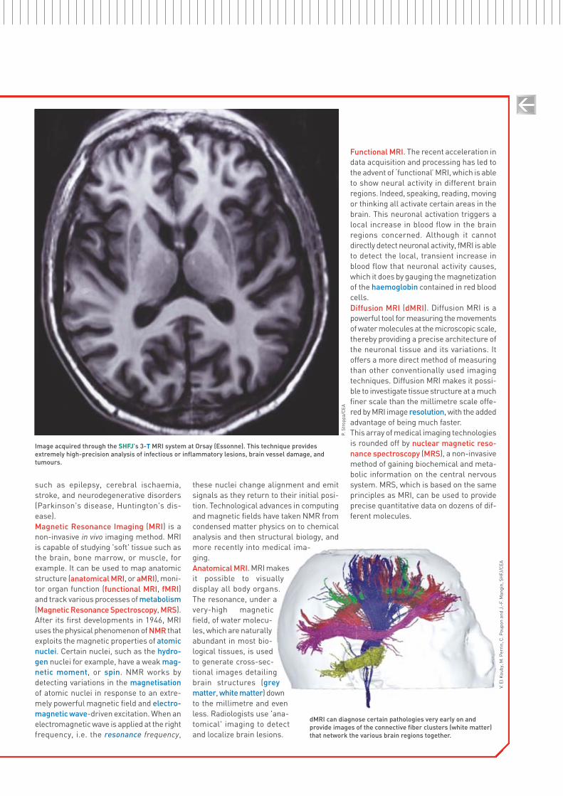
Image acquired through the SHFJ's 3-T MRI system at Orsay (Essonne). This technique providesextremely high-precision analysis of infectious or inflammatory lesions, brain vessel damage, andtumours.
P. S
trop
pa/C
EA
dMRI can diagnose certain pathologies very early on andprovide images of the connective fiber clusters (white matter)that network the various brain regions together.
V. E
l Kou
by, M
. Per
rin,
C. P
oupo
n an
d J.
-F. M
angi
n, S
HFJ
/CEA

Some historical backgroundTrains "flying" above the track usingmagnetic levitation, electricity storagefinally resolved using giant magneticcoils, electrotechnical instruments andelectric power transmission cables withno joule losses, magnetic fields that canbe used to explore the human body anddeliver even higher resolution images.People have been marvelling at thepotential uses of superconductivity since1911 when Dutch physicist HeikeKammerlingh-Onnes first discovered theextraordinary property exhibited bysuperconducting materials; their elec-trical resistance drops to zero below acertain critical temperature (which varieswith their isotopic mass). This discoverywon him the Nobel Prize in Physicsin 1913.Apart from zero electrical resistanceand optimal electrical conductivity, thesuperconductors discovered by Kam -merlingh-Onnes (later named type Isuperconductors) possess anotherremarkable property manifested by theMeissner effect, discovered in 1933 byGerman physicists Walter Meissner and
Robert Ochsenfeld. If we ignore theLondon penetration depth(1), supercon-ductors can be said to exhibit perfect dia-magnetism, i.e. the superconductingmaterial fully expulses its internalmagnetic field up to a certain criticalfield value whereas, in theory, themagnetic field of a material with perfectconduction of electricity should equalthat of the externally applied field.Herein lies the second obstacle thatcontinues to hamper superconductorapplications: superconductivity is lost atabove a critical magnetic field strength.For many years physicists thought therewas only one type of superconductivityand that the magnetic anomalies ob -served in some samples were due solelyto the presence of impurities. Inthe 1950s, however, Russian physicistsVitaly L. Ginzburg and Lev DavidovitchLandau came up with the theory that
there were actually two types of super-conductors.In 1957, the Russian-American physi-cist Alexei A. Abrikosov finally confirmedtype II superconductivity. Type II super-conductors exhibit a completely differenttype of magnetisation characterised bya mixed state that allows them to retaintheir superconducting state even inintense magnetic fields. This means theyare not subject to the Meissner effect.In 2003, Abrikosov, Ginzburg and theAnglo-American physicist Anthony J.Leggett were awarded the Nobel Prizein Physics for their research into super-conductors.It was also in 1957 that American phy-sicists John Bardeen, Leon N. Cooperand John R. Schrieffer published theirtheory of superconductivity, which wonthem the 1972 Nobel Prize in Physics.This BCS theory (named after the firstletter of their surnames) postulates thatelectrons move through a conductor asCooper pairs (two electrons with oppo-site spin). These pairs act like spin-zerobosons and condense into a single quan-tum state via a phonon interaction, which
Superconductivity and superconductorsBFOCUS
One of the main fields of application of superconductivity is medical imaging. This is the 3-tesla magnetic resonance imager at the SHFJ hospital in Orsay (Essonne).
P. S
trop
pa/C
EA
(1) In 1935, Fritz and Heinz London proposedanother explanation for the Meissner effect by claiming that the magnetic field decreases with depth from the surface of a superconductingmaterial over a characteristic length λL known as the penetration depth.
is also a quantized mode of vibration. Itis this electron-phonon interaction thatunderpins resistivity and superconducti-vity. Ions move in response to the ultra-fast passage of an electron (106 m/s), thereby creating an area of positive elec-trical charge which is held after the passage of the electron. This attracts an -other electron that pairs up with the firstelectron thereby resisting the Coulombrepulsion but not thermal agitation, whichexplains why temperature has such anadverse effect on superconductivity.The BCS theory, which applies to 'conventional' superconductors, did nothowever provide for the appearance ofsuperconductivity at fairly high tempera-tures, i.e. higher than the temperature ofliquid nitrogen (77 K, i.e. – 196 °C), and afortiori at ambient temperature. This 77 Kthreshold was reached by using compoundssuch as Y-Ba-Cu-O (current records standat around 165 K, at high pressure, and138 K, i.e. – 135 °C, at standard pressure).German physicist Johannes GeorgBednorz and Swiss physicist KarlAlexander Müller were awarded the NobelPrize in Physics in 1987 for their work onunconventional superconductors. Theydiscovered a lanthanum-based copperoxide perovskite material that exhibitedsuperconducting properties at a tempe-rature of 35 K (- 238 °C). By replacing lan-thanum with yttrium, particularly inYBa2Cu3O7, they were able to significantlyraise the critical temperature thus developing the cuprate family of super-conductors. Although these are highlyeffective superconductors, the fact thatthey are ceramics makes them difficult touse in electrotechnical applications. Allhigh-critical-temperature superconduc-tors are type II superconductors.
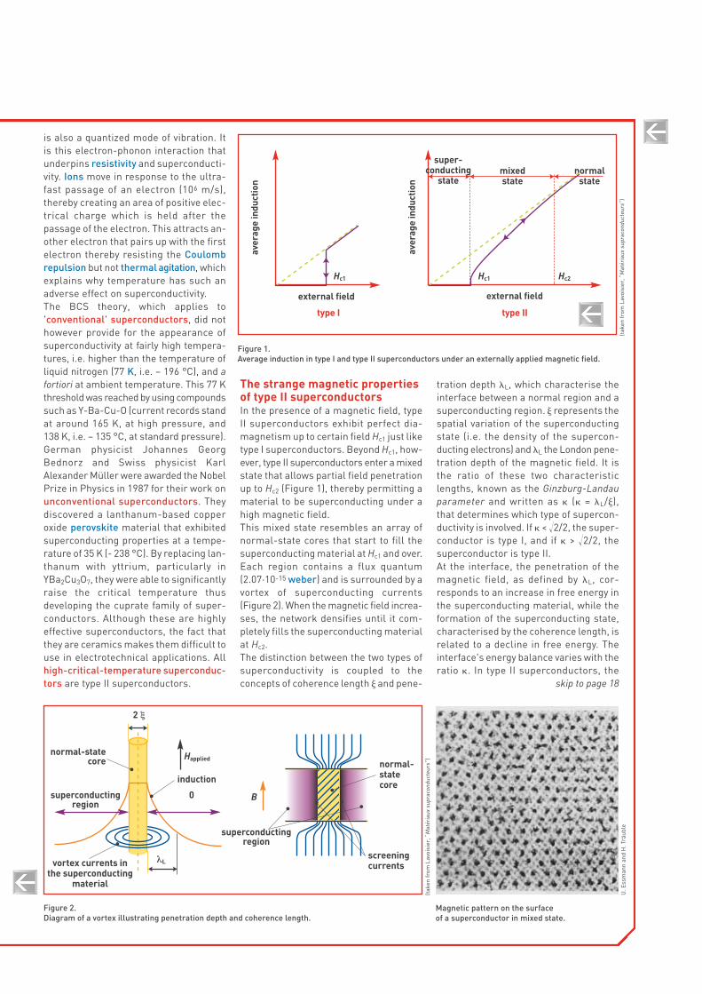
The strange magnetic propertiesof type II superconductorsIn the presence of a magnetic field, typeII superconductors exhibit perfect dia-magnetism up to certain field Hc1 just liketype I superconductors. Beyond Hc1, how -ever, type II superconductors enter a mixedstate that allows partial field penetrationup to Hc2 (Figure 1), thereby permitting amaterial to be superconducting under ahigh magnetic field.This mixed state resembles an array ofnormal-state cores that start to fill thesuperconducting material at Hc1 and over.Each region contains a flux quantum(2.07·10-15 weber) and is surrounded by avortex of superconducting currents(Figure 2). When the magnetic field increa-ses, the network densifies until it com-pletely fills the superconducting materialat Hc2.The distinction between the two types ofsuperconductivity is coupled to theconcepts of coherence length � and pene-
tration depth �L, which characterise theinterface between a normal region and asuperconducting region. � represents thespatial variation of the superconductingstate (i.e. the density of the supercon-ducting electrons) and �L the London pene-tration depth of the magnetic field. It isthe ratio of these two characteristiclengths, known as the Ginzburg-Landauparameter and written as � (� = �L/�),that determines which type of supercon-ductivity is involved. If � < �2/2, the super-conductor is type I, and if � > �2/2, thesuperconductor is type II.At the interface, the penetration of themagnetic field, as defined by �L, cor-responds to an increase in free energy inthe superconducting material, while theformation of the superconducting state,characterised by the coherence length, isrelated to a decline in free energy. Theinterface's energy balance varies with theratio �. In type II superconductors, the
Magnetic pattern on the surface of a superconductor in mixed state.
Figure 2.Diagram of a vortex illustrating penetration depth and coherence length.
skip to page 18
(tak
en fr
om L
avoi
sier
, “M
atér
iaux
sup
raco
nduc
teur
s”)
U. E
ssm
ann
and
H. T
räub
le
Figure 1. Average induction in type I and type II superconductors under an externally applied magnetic field.
(tak
en fr
om L
avoi
sier
, “M
atér
iaux
sup
raco
nduc
teur
s”)
aver
age
indu
ctio
n
external field
type I type II
Hc1
aver
age
indu
ctio
n
external field
super -conducting
statemixed state
normalstate
Hc2Hc1
normal-statecore
2 ξ
normal-statecore
screeningcurrents
superconductingregion
vortex currents inthe superconducting
material
Happlied
superconductingregion
λL
B
induction
0

mixed state therefore results from thecreation of a large number of interfa-ces, with each interface correspondingto a negative energy balance conduciveto superconductivity above the Hc1 field(Table).
Potential avenues for applicationType I superconductivity does not pre-sent any great potential for new areasof application. Unfortunately, the criti-cal temperature that limits supercon-ductivity applications is very low in thetwo superconducting materials thatcurrently offer real-world applicationsi.e. niobium-titanium, NbTi (9.2 K) - thefirst superconducting cables in niobium-titanium alloy were developed in theearly 1960s - and niobium-tin, Nb3Sn(18 K). These materials have to becooled to the temperature of liquidhelium (4.2 K)(2) in order to activate
their superconducting properties. This temperature was the first importantmilestone towards achieving super-conductivity at ambient temperature,which is the ultimate goal.Type II superconductors can withstandvery strong magnetic fields, and arealso able to carry extraordinarily highcurrent densities, up to another criti-cal value that varies with the magneticfield (Figure 3). This fact heralded thedevelopment of the first superconduc-ting magnets. The current densities thatcan be generated under these condi-tions are huge in comparison with whatcan be achieved with domestic or indus-trial electrotechnical applications(around 10 A/mm2).Since the 1970s, the CEA has been focu-sing its research on the production oflarge-scale intense permanent mag -netic fields (magnetic confinement offusion plasmas, particle physics, medi-cal imaging). In fact, these are the pre-
dominant applications of type II super-conductors, mainly NbTi(3), wheresuperconductivity significantly cutsdown on electric power consumptiondespite the cryogenic efficiency of thefacilities - in fact, one watt dissipatedat 4.2 K requires a minimum consump-tion of 300 W at ambient temperaturein the largest industrial power plants.While researchers the world over stilldream of developing superconductingmaterials that function at room tem-perature, it would seem that appliedsuperconductivity will still have to relyon the use of very low temperaturecooling for the foreseeable future.
BFOCUS
(2) The history of superconductivity actuallygoes as far back as William Ramsay who, in1895, was the first person to isolate helium.Indeed, where would the science of superconductivity be today if it wasn't for helium which is the key component of the ultra-low cooling process? Note also that Kammerlingh-Onnes finally succeeded inproducing liquid helium in 1908 followingunsuccessful attempts by James Dewar in the late 19th century, thus paving the way to the discovery of superconductivity.
(3) Produced in quantities of around 1,500 to 2,000 tons per year.
The discovery of high-critical-temperaturesuperconductivity made it possible to see how superconductivity manifests inthe open air in the form of a magnet floatingabove a pellet of liquid-nitrogen cooledYBaCuO, which is now a famous example of the effect.
LEG
Gre
nobl
e
Table.Characteristics of some type I and type II superconductors. μ0·Hc1 and μ0·Hc2 represent magnetic inductions, where μ0 is the magnetic permeabilityof a vacuum (and of the material in this particular case).
material � (μm) �L (μm) � Tc (K) μ0 · Hc1 (teslas) μ0 · Hc2 (teslas)0 K 0 K 0 K 0 K
type I Al 1.36 0.05 0.04 1.18 0.010 5Pb 0.083 0.037 0.5 7.18 0.080 3
type II NbTi 0.005 0.3 60 9.25 0.01 14Nb3Sn 0.003 6 0.065 18 18 0.017 25.5
YBaCuO plane 0.003 plane 0.8 � 300 93 140axis c 0.000 6 axis c 0.2
page 17 cont’d
Figure 3. Characteristic critical current densities in relation to a 4.2-K magnetic field for the two superconducting materials most widely used, particularly in the manufacture of superconducting magnets.
criti
cal c
urre
nt d
ensi
ty(A
/mm
2 )
magnetic field (teslas)
10,000
1,000
100
100 5 10 15 20
niobium-tin
niobium-titanium

The origins of magnetism lie in theproperties of electrons as explained
by the laws of quantum physics. Part ofan electron's magnetic properties (spinmagnetism) results from its quantum-mechanical spin state, while another partresults from the orbital motion of elec-trons around an atom's nucleus (orbitalmagnetism) and from the magnetism ofthe nucleus itself (nuclear magnetism).This is put to use, in particular, for nuclearmagnetic resonance imaging in the medi-cal field. Magnetism is therefore produ-ced by electric charges in motion. Theforce acting on these charges, called theLorentz force, demonstrates the pre-sence of a magnetic field.Electrons have an intrinsic magneticdipole moment (the magnetic quantumstate being the Bohr magneton), whichcan be pictured as an electron's rotatio-nal motion of spin around itself in onedirection or another, oriented eitherupwards or downwards. The spin quan-tum number (one of the four numbers that'quantifies' the properties of an electron)equals 1/2 (+ 1/2 or - 1/2). A pair of elec-trons can only occupy the same orbital ifthey have opposite magnetic dipolemoments.Each atom acts like a tiny magnet car-rying an intrinsic magnetic dipolemoment. A nucleus (the neutron andproton individually have a half-integerspin) will have a half-integer spin if it hasan odd atomic mass number; zero spinif the atomic mass number and chargeare even, and an integer spin if the ato-mic mass number is even and the chargeodd.On a larger scale, several magneticmoments can together form magnetic
domains in which all these moments arealigned in the same direction. These spa-tial regions are separated by domainwalls. When grouped together, thesedomains can themselves form a macro-scopic-scale magnet (Figure E1). The type of magnetism that comes intoplay is determined by how these ele-mentary constituents are ordered, and isgenerally associated with three maincategories of material: ferromagnetic,paramagnetic and diamagnetic. Any material that is not diamagnetic isby definition paramagnetic provided thatits magnetic susceptibility is positive.However, ferromagnetic materials haveparticularly high magnetic susceptibilityand therefore form a separate category.1. Ferromagnetic materials are formedof tiny domains inside which atoms exhi-biting parallel magnetisation tend to alignthemselves in the direction of an exter-nal magnetic field like elementary dipo-les. In fact, the magnetic moments ofeach atom can align themselves sponta-neously within these domains, even inthe absence of an external magnetic field.Applying an external field triggers domainwall movement that tends to strengthenthe applied field. If this field exceeds acertain value, the domain most closelyoriented with the direction of the appliedfield will tend to grow at the expense ofthe other domains, eventually occupyingthe material's whole volume. If the fielddiminishes, the domain walls will move,but not symmetrically as the walls can-not fully reverse back to their originalpositions. This results in remanentmagnetisation, which is an important fea-ture of naturally occurring magnetite, orof magnets themselves.
The whole process forms a hysteresisloop, i.e. when the induced field is plot-ted against the applied field it traces outa hysteresis curve or loop where the sur-face area represents the amount ofenergy lost during the irreversible partof the process (Figure E2). In order tocancel out the induced field, a coercivefield has to be applied: the materials usedto make artificial permanent magnetshave a high coercivity. Ferromagnetic materials generally havea zero total magnetic moment as thedomains are all oriented in different direc-tions. This ferromagnetism disappearsabove a certain temperature, which isknown as the Curie Temperature or Curiepoint.The magnetic properties of a given mate-rial stem from the way the electrons inthe metallic cores of a material or of atransition metal complex collectively cou-ple their spins as this results in all theirspin moments being aligned in the samedirection. Materials whose atoms are widely dis-tributed throughout their crystal struc-ture tend to better align these elemen-tary magnets via a coupling effect. Thiscategory of materials, which is charac-terised by a very high positive magnetic
The different types of magnetismAFOCUS
Figure E2. The induction B of a magnetic material by a coilis not proportional to its magnetic excitation(field H). While the initial magnetisation formsan OsS-type curve, shown in blue in the figure,it reaches saturation at point s. Only a partialinduction is retained if the field approacheszero; this remanent induction can only becancelled out by reversing the magnetic field to a "coercive" field value. This hysteresis loopillustrates the losses due to "friction" betweenthe magnetic domains shown on the areabounded by the magnetisation anddemagnetisation curves.
Figure E1.Intrinsic magnetic dipole moments have parallel alignment in ferromagnetic materials (a), anti-parallel alignment but zero magnetisation in antiferromagnetic materials (b), and anti-parallelalignment with unequal moments in ferrimagnetic materials (c).
a b c
B
O
S
H
S’
s+BR
-BR
-HS -HC
+HC +HS

susceptibility, includes iron, cobalt andnickel and their alloys, steels in particu-lar, and some of their compounds, and, toa lesser extent, some rare earth metalsand alloys with large crystal lattices, andcertain combinations of elements that donot themselves belong to this category. Inferrimagnetic materials, the magneticdomains group into an anti-parallel align-ment but retain a non-zero magneticmoment even in the absence of an exter-nal field. Examples include magnetite,ilmenite and iron oxides. Ferrimagnetismis a feature of materials containing twotypes of atoms that behave as tiny magnetswith magnetic moments of unequal magni-tude and anti-parallel alignment. Anti-ferromagnetism occurs when the sum ofa material's parallel and anti-parallelmoments is zero (e.g. chromium or hae-matite). In fact, when atoms are in a closeconfiguration, the most stable magneticarrangement is an anti-parallel alignmentas each magnet balances out its neigh-bour so to speak (Figure E1). 2. Paramagnetic materials behave in asimilar way to ferromagnetic materials,although to a far lesser degree (they havea positive but very weak magnetic sus-ceptibility of around 10- 3). Each atom in aparamagnetic material has a non-zeromagnetic moment. In the presence of anexternal magnetic field, the magneticmoments align up, thus amplifying thisfield. However, this effect decreases astemperature rises since the thermal agi-tation disrupts the alignment of the ele-mentary dipoles. Paramagnetic materialslose their magnetisation as soon as theyare released from the magnetic field. Mostmetals, including alloys comprising ferro-magnetic elements are paramagnetic, as
are certain minerals such as pegmatite. 3. Diamagnetic materials exhibit a nega-tive and an extremely weak magnetic sus-ceptibility of around 10- 5. The magnetisa-tion induced by a magnetic field acts in theopposite direction to this field and tendsto head away from field lines towards areasof lower field strengths. A perfect diama-gnetic material would offer maximumresistance to an external magnetic fieldand exhibit zero permeability. Metals suchas silver, gold, copper, mercury or lead,plus quartz, graphite, the noble gases andthe majority of organic compounds are alldiamagnetic materials. In fact, all materials exhibit diamagneticproperties to a greater or lesser extent,resulting from changes in the orbitalmotion of electrons around atoms inresponse to an external magnetic field, aneffect that disappears once the externalfield is removed. As Michael Faraday sho-wed all that time ago, all substances canbe "magnetised" to a greater or lesserdegree provided that they are placed withina sufficiently intense magnetic field.
ElectromagnetismIt was the Danish physicist Hans ChristianØrsted, professor at the University ofCopenhagen, who, in 1820, was first to dis-cover the relationship between the hithertoseparate fields of electricity and magne-tism. Ørsted showed that a compass needlewas deflected when an electric currentpassed through a wire, before Faraday hadformulated the physical law that carrieshis name: the magnetic field produced isproportional to the intensity of the current.Magnetostatics is the study of staticmagnetic fields, i.e. fields which do notvary with time.
Magnetic and electric fields together formthe two components of electromagnetism.Electromagnetic waves can move freelythrough space, and also through mostmaterials at pretty much every frequencyband (radio waves, microwaves, infrared,visible light, ultraviolet light, X-rays andgamma rays). Electromagnetic fields the-refore combine electric and magnetic forcefields that may be natural (the Earth'smagnetic field) or man-made (low fre-quencies such as electric power trans-mission lines and cables, or higher fre-quencies such as radio waves (includingcell phones) or television.Mathematically speaking, the basic lawsof electromagnetism can be summarisedin the four Maxwell equations (or Maxwell-Lorentz equations) which can be used toprovide a coherent description of all elec-tromagnetic phenomena from electrosta-tics and magnetostatics to electromagne-tic wave propagation. James Clerk Maxwellset out these laws in 1873, thirty-two yearsbefore Albert Einstein incorporated thetheory of electromagnetism in his specialtheory of relativity, which explained theincompatibilities with the laws of classi-cal physics.
Stoi
ber
Pro
duct
ions
, Mün
chen
A Transrapid train using magnetic levitation arriving at the Long Yang bus station in Shanghai (China).This German-built high-speed, monorail train was commissioned in 2004 to service the rail link
to Pudong international airport.
Close-up of the magnets used to guide and power the train.