SUPERCAPACITOR ELECTRODES BASED ON · PDF fileABSTRACT SUPERCAPACITOR ELECTRODES BASED ON...
26
SUPERCAPACITOR ELECTRODES BASED ON GRAPHENE MATERIALS A Term Paper Presented to Prof. Barbara Murphy-Wesley San Jos´ e State University In Partial Fulfillment of the Requirements for Completion of E200W by Steven M. Selverston November 2011
Transcript of SUPERCAPACITOR ELECTRODES BASED ON · PDF fileABSTRACT SUPERCAPACITOR ELECTRODES BASED ON...
SUPERCAPACITOR ELECTRODES BASED ON GRAPHENE MATERIALS
A Term Paper
Presented to
Prof. Barbara Murphy-Wesley
San Jose State University
In Partial Fulfillment
of the Requirements for Completion of
E200W
by
Steven M. Selverston
November 2011

c� 2011
Steven M. Selverston
ALL RIGHTS RESERVED
ABSTRACT
SUPERCAPACITOR ELECTRODES BASED ON GRAPHENE MATERIALS
by Steven M. Selverston
Graphene is a new type of carbon material with promising potential in
energy-storage applications such as supercapacitor electrodes. This paper introduces
engineering of graphene, as well as a related material called reduced graphene oxide,
as materials for use in supercapacitors. The introduction explains the basic
definitions of supercapacitors and graphene materials. Then, the fundamentals of
supercapacitors and graphene materials are described in more detail in Chapters 1
and 2, respectively. Chapter 3 covers the synthesis and characterization of
graphene-based electrodes.
iv

DEDICATION
To my parents, without whose support this would not have been possible.
v

ACKNOWLEDGEMENTS
I would like to thank Prof. Barbara Murphy-Wesley for a great E200W class.
Also, I would like to thank Richard Chung, Bin Chen, and Mike Oye for all the
thoughtful advice and help. Finally, I’d like to thank Prof. Tim Hsu of the SJSU
Math department for updating and providing the LATEX thesis style guide.
vi
TABLE OF CONTENTS
CHAPTER
1 INTRODUCTION 1
2 SUPERCAPACITORS 3
2.1 Capacitive charge storage . . . . . . . . . . . . . . . . . . . . . . . . 3
2.2 Double-layer and pseudocapacitance . . . . . . . . . . . . . . . . . . . 5
3 GRAPHENE 7
3.1 Graphene materials . . . . . . . . . . . . . . . . . . . . . . . . . . . . 7
3.2 Reduced graphene oxide . . . . . . . . . . . . . . . . . . . . . . . . . 8
3.3 Composites . . . . . . . . . . . . . . . . . . . . . . . . . . . . . . . . 9
4 GRAPHENE-BASED ELECTRODES 10
4.1 Characterization . . . . . . . . . . . . . . . . . . . . . . . . . . . . . 10
4.2 Graphene and electrode synthesis . . . . . . . . . . . . . . . . . . . . 13
4.3 State of the art . . . . . . . . . . . . . . . . . . . . . . . . . . . . . . 14
5 CONCLUSION 17
REFERENCES 18
vii
LIST OF FIGURES
Figure
1 Ragone comparison of energy storage devices [1] . . . . . . . . . . . 1
2 Double-layer charge storage mechanism . . . . . . . . . . . . . . . . . 3
3 Difference between graphite and graphene structures . . . . . . . . . 7
4 Model of graphite oxide proposed by Szabo et al. [2], illustrated by
Dreyer et al. [3] . . . . . . . . . . . . . . . . . . . . . . . . . . . . . . 8
5 Cyclic voltammetry of a graphene-based composite electrode at various
scan rates [4] . . . . . . . . . . . . . . . . . . . . . . . . . . . . . . . 11
6 Nyquist plot of a graphene-based composite electrode [4] . . . . . . . 12
7 Reduced ESR in a vertically-oriented graphene electrode [5] . . . . . 16
viii
CHAPTER 1
INTRODUCTION
R. Kotz, M. Carlen / Electrochimica Acta 45 (2000) 2483–24982484
where typical energy storage and conversion devices arepresented in the so called ‘Ragone plot’ in terms oftheir specific energy and specific power. Electrochemicalcapacitors fill in the gap between batteries and conven-tional capacitors such as electrolytic capacitors ormetallized film capacitors. In terms of specific energy aswell as in terms of specific power this gap covers severalorders of magnitude.
Batteries and low temperature fuel cells are typicallow power devices whereas conventional capacitorsmay have a power density of !106 watts per dm3 atvery low energy density. Thus, electrochemical capaci-tors may improve battery performance in terms ofpower density or may improve capacitor performancein terms of energy density when combined with therespective device. In addition, electrochemical capaci-tors are expected to have a much longer cycle life thanbatteries because no or negligibly small chemical chargetransfer reactions are involved. A monograph volumeon electrochemical capacitors was recently published byConway [4].
In the following the basic principal of electrochemicalcapacitors, the different types of ECs, some theoreticalconsiderations as to the performance of ECs, and someapplications will be discussed.
2. Principle of energy storage
Electrochemical capacitors store the electric energy inan electrochemical double layer (Helmholtz Layer)formed at a solid/electrolyte interface. Positive andnegative ionic charges within the electrolyte accumulate
at the surface of the solid electrode and compensate forthe electronic charge at the electrode surface. The thick-ness of the double layer depends on the concentrationof the electrolyte and on the size of the ions and is inthe order of 5–10 A! for concentrated electrolytes. Thedouble layer capacitance is about 10–20 !F/cm2 for asmooth electrode in concentrated electrolyte solutionand can be estimated according to equation Eq. (1)
C/A=!0*!r/d (1)
assuming a relative dielectric constant !r of 10 for waterin the double layer [5]. d being the thickness of thedouble-layer with surface area A. The correspondingelectric field in the electrochemical double layer is veryhigh and assumes values of up to 106 V/cm easily.Compared to conventional capacitors where a totalcapacitance of pF and !F is typical, the capacitance ofand the energy density stored in the electrochemicaldouble layer is rather high per se and the idea to builda capacitor based on this effect is tempting.
In order to achieve a higher capacitance the electrodesurface area is additionally increased by using porouselectrodes with an extremely large internal effectivesurface. Combination of two such electrodes gives anelectrochemical capacitor of rather high capacitance.
Fig. 2 shows a schematic diagram of an electrochem-ical double-layer capacitor consisting of a single cellwith a high surface-area electrode material, which isloaded with electrolyte. The electrodes are separated bya porous separator, containing the same electrolyte asthe active material. The potential drop across the cell isalso shown in Fig. 2.
Fig. 1. Sketch of Ragone plot for various energy storage and conversion devices. The indicated areas are rough guide lines.
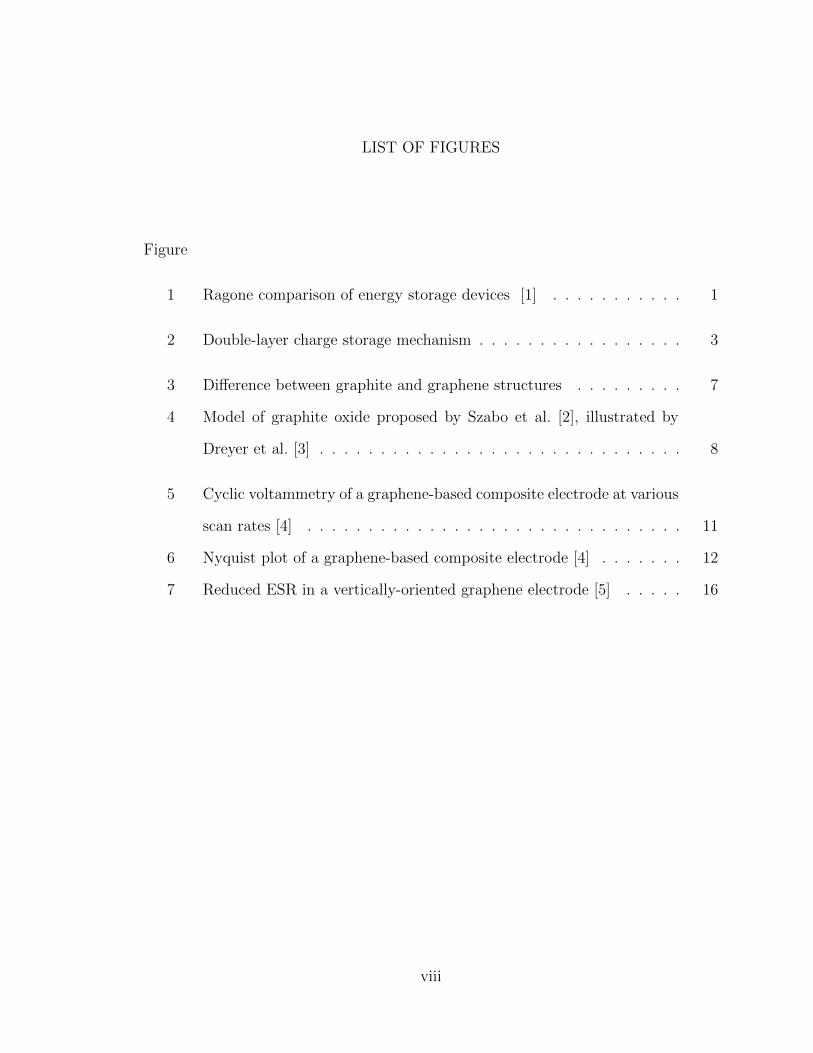
Figure 1: Ragone comparison of energy storage devices [1]
Capacitors are energy storage devices similar to batteries, but which use
different mechanisms. Namely, batteries store energy chemically, and capacitors
store it physically (through dielectric polarization or ionic double-layers). Using
chemical storage allows batteries to store relatively large amounts of energy, but
there are several disadvantages. In many cases, the lifetime of a galvanic battery is
relatively short. Typically, advanced batteries can be completely cycled no more
than a few thousand times. Another problem with batteries is the relatively low
power density, which means that the device cannot be charged or discharged quickly
without overheating and perhaps being destroyed. An general comparison of the
energy characteristics of capacitors, electrochemical capacitors (supercapacitors),
batteries, and fuel cells is shown in Figure 1. Generally, fuel cells and batteries can
store more energy by weight, but capacitors can charge and discharge faster (lower
RC time constants).
Supercapacitors, also known as electrochemical capacitors or ultracapacitors,
can overcome some of the limitations of batteries, but generally cannot replace
them. Rather, they can be used in certain applications where batteries fail (ex:
regenerative braking), and also they can be used as supplements to batteries (ex:
hybrid engine-starting modules). Supercapacitors are similar in principle to
capacitors, but they use a different mechanism for charge storage. Instead of storing
the charge directly in dielectric materials, supercapacitors use electrolyte ions,
which create charge storage in electrical double layers. A subclass of
supercapacitors, called pseudocapacitors, exploits yet another mechanism for charge
storage via faradaic chemical reactions at the anode. The other subclass of
supercapacitors is electrochemical double-layer capacitors (EDLC), which use
almost entirely double-layer charge storage. In general, supercapacitor performance
depends most strongly on the electrode materials engineering.
Ever since the 2009 Nobel Prize in physics was given to Andre Geim and
Konstantin Novoselov for their work on single-layer graphite [6], which is usually
called graphene, engineers worldwide have attempted to see if graphene can be used
for practical applications. A related graphene material is called reduced graphene
oxide (RGO), which is similar to graphene but with more structural disorder and
more oxygen functionalities. One of the many possible applications of graphene
materials is for electrodes, and in particular for supercapacitor electrodes.
2
CHAPTER 2
SUPERCAPACITORS
+
+
+
+
+
+
+ +
+
+
+ +
+
+++
++
+
++
+++ +
++++
+ +++
+
+
--
--
-- - -
---
- - ---
- ---
--
-- -
-- -
-
-
✲anode ✛ cathode
✻
porous separator
activated carbon
✑✑
✑✑✑✰
❍❍❍❍❍❥
cations��✒
anions❅❅■
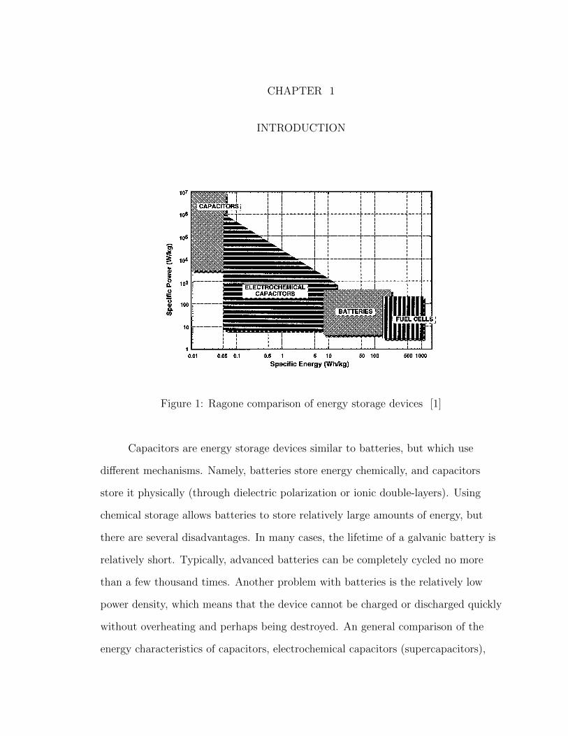
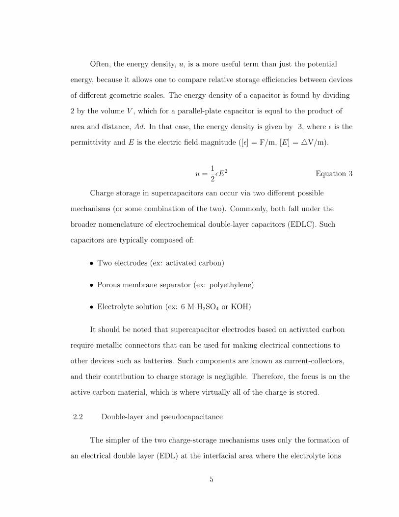
Figure 2: Double-layer charge storage mechanism
2.1 Capacitive charge storage
To understand supercapacitors, it is necessary to understand common
capacitors. Some of the first capacitors were built in the mid-1800s by Michael
Faraday (1791-1867), and were referred to as “condensers.” The devices had a
capacity to store electrical charge, and therefore eventually came to be known as
capacitors. The common capacitor is composed of only three parts: two metallic
electrodes (ex: aluminum) and one dielectric separator (ex: stretched-out
polyethylene).
3
A dielectric is a material that becomes polarized in an electric field. That is,
the material does not (ideally) allow DC charges to pass through it, but rather the
material itself becomes electrically polarized. This polarization occurs when, for
example, a battery is connected to the capacitor electrodes. The electrode that is
connected to the positive terminal of the battery is known as the anode, and the
electrode connected to the negative terminal of the battery is known as the cathode.
When the battery is connected to the capacitor, electrical charge flows from the
battery into the capacitor, but not through it. Instead of passing through the
electrodes, the charges accumulate on the electrodes. That charge accumulation,
which is proportional to the amount of polarization of the dielectric, is the
mechanism for charge storage and therefore energy storage.
Capacitance is defined by the ratio of stored charge, Q, over the potential
difference between the electrodes, �V , as shown in Equation 1. The term �
represents the permittivity of the material between the plates. In a vacuum,
� � 8.85 ∗ 10−12 F/m.
Even after the power supply is disconnected from the plates, the charges
remain. The capacitor is then said to be “charged,” and it can be used to supply
power to other devices. The SI unit of capacitance is the farad, and one farad (F) is
defined as 1 coulomb per volt (C/V).
C ≡ Q
� V= �
A
dEquation 1
The potential energy stored in a capacitor can be calculated according to
Equation 2.
U =Q2
2C=
1
2C�V 2 Equation 2
4
Often, the energy density, u, is a more useful term than just the potential
energy, because it allows one to compare relative storage efficiencies between devices
of different geometric scales. The energy density of a capacitor is found by dividing
2 by the volume V , which for a parallel-plate capacitor is equal to the product of
area and distance, Ad. In that case, the energy density is given by 3, where � is the
permittivity and E is the electric field magnitude ([�] = F/m, [E] = �V/m).
u =1
2�E2 Equation 3
Charge storage in supercapacitors can occur via two different possible
mechanisms (or some combination of the two). Commonly, both fall under the
broader nomenclature of electrochemical double-layer capacitors (EDLC). Such
capacitors are typically composed of:
• Two electrodes (ex: activated carbon)
• Porous membrane separator (ex: polyethylene)
• Electrolyte solution (ex: 6 M H2SO4 or KOH)
It should be noted that supercapacitor electrodes based on activated carbon
require metallic connectors that can be used for making electrical connections to
other devices such as batteries. Such components are known as current-collectors,
and their contribution to charge storage is negligible. Therefore, the focus is on the
active carbon material, which is where virtually all of the charge is stored.
2.2 Double-layer and pseudocapacitance
The simpler of the two charge-storage mechanisms uses only the formation of
an electrical double layer (EDL) at the interfacial area where the electrolyte ions
5
meet the electrode, as in Figure 2. An electrolyte solution such as potassium
hydroxide provides charged ions that form double layers when the electrodes are
connected to a power supply such as a battery. Electrolyte choice and optimization
is not necessarily trivial, and there is significant research focusing on both aqueous
electrolytes and ionic liquids.
Pseudocapacitance, the more complex mechanism of charge-storage, uses
chemical (faradaic) reactions on the anode. The anodic chemical charge storage of
pseudocapacitors is distinct from that which occurs in batteries, and typically is
based on metal oxides (ex: RuO2, MnO2) or specialized polymers. In both cases of
“pure” double layer capacitors (EDLC) and pseudocapacitors, the electrode
material properties are of fundamental importance.
6
CHAPTER 3
GRAPHENE
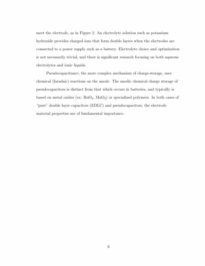
(a) graphite structure (hcp) (b) single-layer graphene
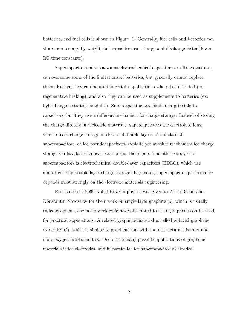
Figure 3: Difference between graphite and graphene structures
3.1 Graphene materials
By far, the most common element used for supercapacitors is carbon. When
graphitic carbon is treated for improved properties such as high porosity, it is
usually called activated carbon. High porosity is desirable because it implies high
surface area for EDL formation (more contact area between electrolyte ions and the
plates). Nearly all commercial supercapacitors use electrodes based on activated
carbon materials because of its relatively low cost. In the last decade, many
attempts have been made to use other, more advanced forms of carbon to build
supercapacitor electrodes. In particular, carbon nanotubes have been of primary
interest. Carbon nanotubes are very similar to graphene materials; if a single-wall
carbon nanotube (SWCNT), taking the shape of a straw, were to be cut down one
7
edge and flattened out, its wound then be called a graphene sheet or carbon
nanosheet. Conversely, if a sheet of graphene were to be rolled up into the shape of
a straw, it would then be called a carbon nanotube.
Graphene is simply a single layer of graphite. A single sheet of graphite,
however, has properties significantly different from many-layer graphite.
Furthermore, bilayer and trilayer graphene also have unique respective properties.
Electrical and thermal conductivities, strength, and surface area are all different
between graphene and graphite. In many cases, the properties of graphene are more
desirable. In practice, conductivity of a single-layer graphene sheet has been
measured up to 649 S/cm [7]. This value is similar to that of graphite, but well
below the conductivity of copper, which is in the order of 105 S/cm. The most
important property of graphene with respect to supercapacitors is, naturally, its
high theoretical specific surface area of 2675 m2/g and the corresponding theoretical
specific capacitance of 550 F/g [4].
3.2 Reduced graphene oxide
carboxylic acid groups were present in very low quantitiesat the periphery of the graphitic platelets, in addition toother keto groups.22,32,33 The key features of this model aresummarized in Fig. 2.
As Brodie observed in 1859, along with many others since,Lerf and coworkers noted the thermal instability of GO. Aftercalcinating in a vacuum at 100 1C, the signals found at d = 60and 70 ppm in the 13C NMR spectrum of the resultingmaterial disappeared, leaving only a signal at 122 ppm. Theyattributed this signal to the presence of aromatic and phenolic(or aromatic diol) species.34w The decomposition process(discussed in greater detail below) is known to involve theevolution of CO and CO2, rather than O2, due to the highsurface reactivity of GO itself.35 Thermal decomposition(in ambient atmosphere) at higher temperatures was reportedto result in a highly-disordered mixture of various oxygen-containing graphitic carbons that are di!cult to characterize.Though the Lerf–Klinowski model remains largely unchangedsince its initial report over 10 years ago, others have madeslight modifications to the proposed structure including thepresence of 5- and 6-membered lactols on the periphery ofthe graphitic platelets as well as the presence of esters of thetertiary alcohols on the surface, though all accounts maintainthe dominance of epoxides and alcohols on the basalplane.36,37 Cai et al. have also recently demonstrated theability to isotopically label GO, greatly expanding the scopeof potential spectroscopic techniques that may be applied tothe study of its structure (Fig. 4).36
One notable exception to this adherence to the Lerf–Klinowski model has been proposed by Dekany andcoworkers (Fig. 5).27 The Dekany model work revived and
updated the Ruess and Scholz–Boehm models, whichsuggested a regular, corrugated quinoidal structure interruptedby trans-linked cyclohexyl regions, functionalized by tertiaryalcohols and 1,3-ethers. Reevaluation of the FTIR featuresof GO, as well as examination by DRIFT spectroscopy,38
suggested that the signal found at 1714 cm!1 in the IRspectrum of this material was not indicative of carboxylicacids, but rather of single ketones and/or quinones. However,potentiometric acid–base titrations indicated the presence ofacidic sites on the basal plane of GO.39 To explain thisapparent discrepancy, the Lerf–Klinowski model necessitatesa keto-enol isomerization of a,b-unsaturated ketonesgenerated in situ, with the enol form providing the protonexchange site. The keto form is thermodynamically morefavored, however, disfavoring enolization and acidic protonexchange. However, if the enols are present in aromaticregions (e.g. phenol–quinone exchange), the phenoxide isthe thermodynamic product and therefore should allow forproton exchange.In light of these results, the Dekany model is composed
of two distinct domains: trans-linked cyclohexyl speciesinterspersed with tertiary alcohols and and 1,3-ethers, and acorrugated network of keto/quinoidal species. No carboxylicacids are believed to be present in this description of GO.Further oxidation destroys the alkenes of the quinonesthrough formation of 1,2-ethers, as well as any pockets ofaromaticity that may have persisted during the initial oxidativeconditions used for its synthesis. It is also hypothesized thatthe quinones introduce rigidity and plane boundaries, and area possible source of the macroscopic wrinkling of the plateletscommonly seen in TEM images.27
As a final note, variations in the degree of oxidation caused bydi"erences in starting materials (principally the graphite source) oroxidation protocol can cause substantial variation in the structureand properties of the material, rendering the term ‘‘graphiteoxide’’ somewhat fluid, and subject to misinterpretation.This experimental observation has been compared with densityfunctional calculations, which predict that partial oxidation isthermodynamically favored over complete oxidation.40 However,the exact identity and distribution of oxide functional groupsdepends strongly on the extent of coverage. This is illustrated inthe theoretical prediction that the ratio of epoxides to alcoholsincreases with increasing oxidation.40
Fig. 4 (A) 1D 13CMAS and (B) 2D 13C/13C chemical-shift correlation
solid-state NMR spectra of 13C-labeled GOwith (C) slices selected from
the 2D spectrum at the indicated positions (70, 101, 130, 169, and
193 ppm) in the o1 dimension. The green, red, and blue areas in (B) and
circles in (C) represent cross peaks between sp2 and C–OH/epoxide
carbons (green), those between C–OH and epoxide carbons (red), and
those within sp2 groups (blue), respectively (from ref. 36).
Fig. 5 Structure of GO proposed by Dekany and coworkers (adapted
from ref. 27).
w Notably, this most recent model proposed by Lerf, Klinowski andcoworkers does not include the carboxylic acid groups proposedearlier and supported by IR data.22,32,33
232 | Chem. Soc. Rev., 2010, 39, 228–240 This journal is "c The Royal Society of Chemistry 2010
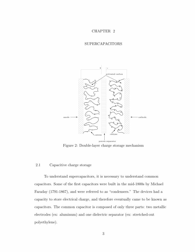
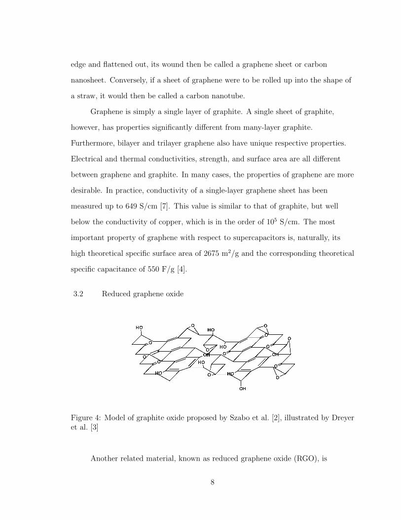
Figure 4: Model of graphite oxide proposed by Szabo et al. [2], illustrated by Dreyeret al. [3]
Another related material, known as reduced graphene oxide (RGO), is
8
sometimes called graphene. Although RGO is significantly different from graphene,
it retains some of the desirable properties such as high surface area. Reduced
graphene oxide is made by reducing graphene oxide, which is made by exfoliating
graphite oxide. Graphite oxide is made via a Hummers’ reaction in solution [8]. The
reduction can be accomplished chemically with sodium borohydride (NaBH4) or
hydrazine (N2H4). Alternatively, the graphene oxide can also be reduced thermally
or electrochemically. The resulting RGO is sometimes called graphene, although
there are some important differences. Firstly, RGO usually has a significant amount
of residual oxygen (ex: several percent). Secondly, RGO is highly disordered and
distorted compared to pristine graphene. Finally, RGO is rarely single-layer (also
called monolayer), but rather it is usually “few-layer,” which usually means about 2
- 10 graphene layers.
3.3 Composites
Both graphene and RGO are frequently made into composites for
experimental electrode devices [4]. Composite materials can be simple to make
when various materials (ex: conductivity boosters, adhesive binders, etc.) are mixed
together. The electrical conductivity of most graphene materials is not exceptional,
so conductive additives are often used. Binders are required in order to glue the
materials together. There are disadvantages to these types of composites, however,
because the high porosity causes pore resistance (impedance), which increases the
capacitor time constant. Additives also reduce active surface area for double-layer
charge storage. Graphene-based composites can also be made other methods that
avoid binders (ex: electrophoretic impregnation). For pseudocapacitive electrodes,
metal oxides or polymers can be made into composites with the carbon materials.
9

CHAPTER 4
GRAPHENE-BASED ELECTRODES
4.1 Characterization
Perhaps the most difficult aspect involved in building new materials is
characterization, and graphene is no exception. The characterization of graphene
and graphene-based electrode materials is an intensive process, requiring
state-of-the-art instruments. Some of the most frequently used characterization
tools include:
• Scanning electron microscopy (SEM): a visualization tool for imaging on the
order of 30 nm to 1 µm
• Cyclic voltammetry (CV): an electrochemical method used to quickly check
capacitance and chemical reactivity of potential electrode materials
• Atomic-force microscopy (AFM) : a visualization and
thickness-measurement tool for very small length scales on the order of 5 -
50 nm
• Electrochemical impedance spectroscopy (EIS): a method used to determine
information regarding porosity and equivalent-series-resistance (ESR)
• Raman spectroscopy (RS): a laser-based method that returns structural
“fingerprints” of materials
There are at least five different experiments that can be used to estimate the
capacitance of an electrode, including galvanostatic charge/discharge, voltage and
10
current sweeping techniques, self-discharge through known resistance, and ac
impedance spectroscopy [9].
Compared with the literature data based on EDL alone,as shown in Figure 4b, the room temperature energy densityof our curved graphene-based supercapacitors is muchhigher than the value of 31.9 Wh/kg (75 F/g) at 60 °C for agraphene-ionic liquid supercapacitor,16 the values of 4.7 Wh/kg (135 F/g) and 21.5 Wh/kg (99 F/g) for a chemicallymodified graphene supercapacitor with aqueous and organicelectrolytes, respectively17 and the separately reported val-ues of 7.1 Wh/kg (205 F/g)18 and 9.2 Wh/kg (264 F/g).19 InFigure 4d, the Nyquist plot of the curved graphene basedsupercapacitor shows a straight line in the low-frequencyregion and an arc in the high frequency region. This highfrequency loop is related to the electronic resistance be-tween graphene sheets. The vertical shape at lower frequen-cies indicates a pure capacitive behavior, representative ofthe ion diffusion in the electrode structure. The more verticalthe curve, the more closely the supercapacitor behaves asan ideal capacitor.18 The magnitude of equivalent seriesresistance (ESR) of 3.31 ohm is obtained from the x-interceptof the Nyquist plot in Figure 4d. ESR data determines therate that the supercapacitor can be charged/discharged.Although the ionic liquid has a viscosity higher than aqueousand organic electrolyte, the mesoporous structure (mostly2-25 nm) constituted by curved graphene sheets remaincapable of delivering a high power density.
FIGURE 3. (a) Galvanostatic charge-discharge curve of a curvedgraphene electrode (6.6 mg each) at a constant current density of 1A/g, using EMIMBF4 ionic liquid electrolyte, and (b) cyclic voltam-mograms for graphene electrode at different scan rates usingEMIMBF4 ionic liquid electrolyte.
FIGURE 4. (a) Ragone plot of graphene supercapacitor, (b) relation-ship between the energy density and current density of a curvedgraphene electrode in EMIMBF4 ionic liquid electrolyte, (c) dischargecurve at 2, 4, and 8 A/g current density, and (d) Nyquist plot forgraphene electrode using a sinusoidal signal of 5 mV over thefrequency range from 100 kHz to 1 mHz. Z! is real impedance. Z!! isimaginary impedance.
© 2010 American Chemical Society 4866 DOI: 10.1021/nl102661q | Nano Lett. 2010, 10, 4863-–4868
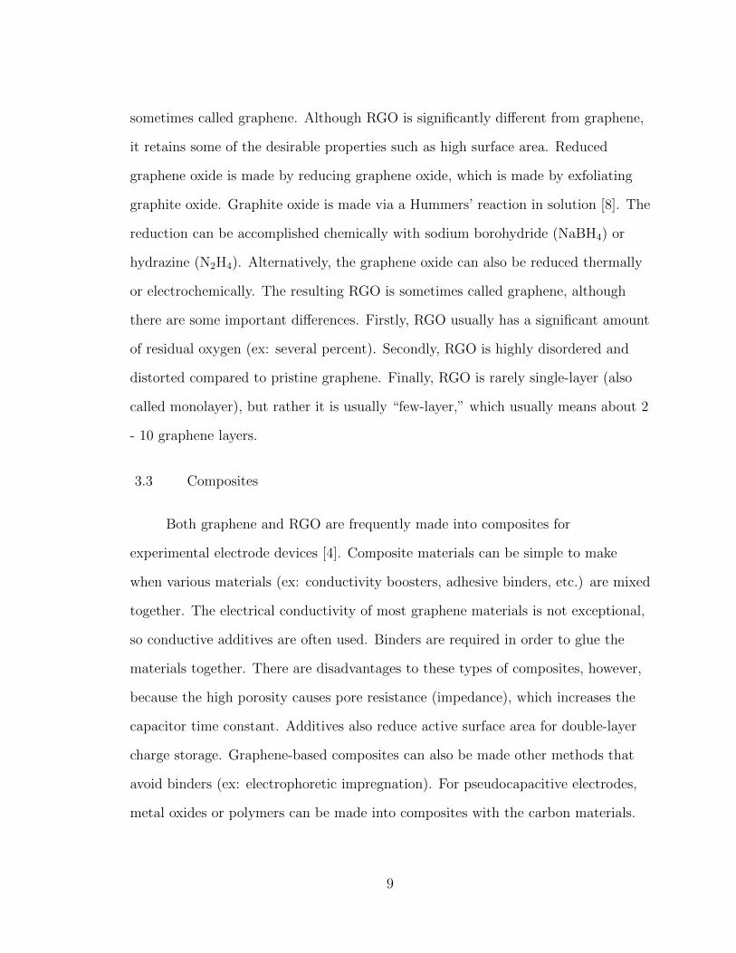
Figure 5: Cyclic voltammetry of a graphene-based composite electrode at variousscan rates [4]
Most supercapacitor characterization is performed using comprehensive
electrochemical workstations that can perform dozens of tests. One can determine
the capacitance of an ideally-polarizable electrode according to Equation 4, wherein
the capacitance is calculated as the inverse of the slope of the linear portion of the
plot of potential as a function of time while the electrode is charged at constant
current [9].
C =
�i · �t
�VEquation 4
To determine the capacitance from cyclic voltammetry (CV), one generally
uses the area of the either the anodic or cathodic portion. A typical CV plot is
shown in Figure 5. In some cases, an average is taken between the two. That case is
11
shown in Equation 5, where�idV is the total area of the CV curve, m is the mass
of the active electrode material (ex: graphene-based composite), �V is the range of
voltage, and �V�T is the scan rate.
C =
�idV
2m�V (�V�T )
Equation 5
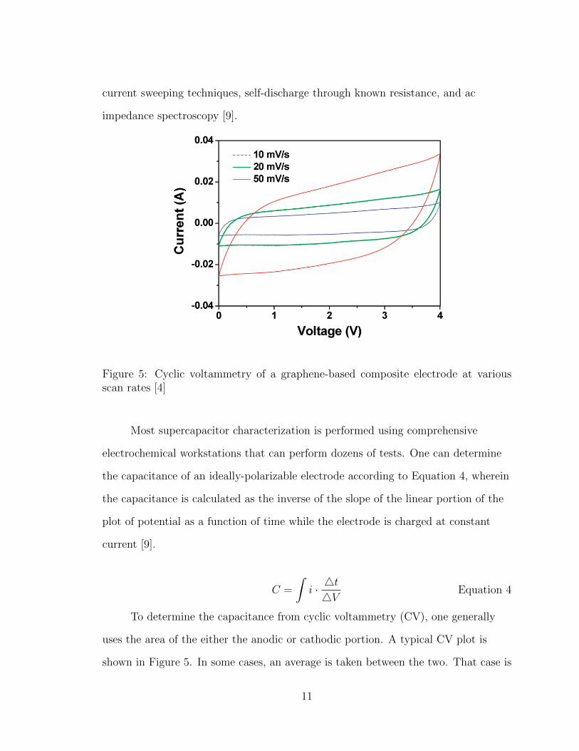
In the case of thin-film electrode materials, the mass term m can be very
challenging to obtain experimentally, so it is sometimes estimated. This is because
the deposited mass may be on the order of micrograms (µg).
Compared with the literature data based on EDL alone,as shown in Figure 4b, the room temperature energy densityof our curved graphene-based supercapacitors is muchhigher than the value of 31.9 Wh/kg (75 F/g) at 60 °C for agraphene-ionic liquid supercapacitor,16 the values of 4.7 Wh/kg (135 F/g) and 21.5 Wh/kg (99 F/g) for a chemicallymodified graphene supercapacitor with aqueous and organicelectrolytes, respectively17 and the separately reported val-ues of 7.1 Wh/kg (205 F/g)18 and 9.2 Wh/kg (264 F/g).19 InFigure 4d, the Nyquist plot of the curved graphene basedsupercapacitor shows a straight line in the low-frequencyregion and an arc in the high frequency region. This highfrequency loop is related to the electronic resistance be-tween graphene sheets. The vertical shape at lower frequen-cies indicates a pure capacitive behavior, representative ofthe ion diffusion in the electrode structure. The more verticalthe curve, the more closely the supercapacitor behaves asan ideal capacitor.18 The magnitude of equivalent seriesresistance (ESR) of 3.31 ohm is obtained from the x-interceptof the Nyquist plot in Figure 4d. ESR data determines therate that the supercapacitor can be charged/discharged.Although the ionic liquid has a viscosity higher than aqueousand organic electrolyte, the mesoporous structure (mostly2-25 nm) constituted by curved graphene sheets remaincapable of delivering a high power density.
FIGURE 3. (a) Galvanostatic charge-discharge curve of a curvedgraphene electrode (6.6 mg each) at a constant current density of 1A/g, using EMIMBF4 ionic liquid electrolyte, and (b) cyclic voltam-mograms for graphene electrode at different scan rates usingEMIMBF4 ionic liquid electrolyte.
FIGURE 4. (a) Ragone plot of graphene supercapacitor, (b) relation-ship between the energy density and current density of a curvedgraphene electrode in EMIMBF4 ionic liquid electrolyte, (c) dischargecurve at 2, 4, and 8 A/g current density, and (d) Nyquist plot forgraphene electrode using a sinusoidal signal of 5 mV over thefrequency range from 100 kHz to 1 mHz. Z! is real impedance. Z!! isimaginary impedance.
© 2010 American Chemical Society 4866 DOI: 10.1021/nl102661q | Nano Lett. 2010, 10, 4863-–4868
Figure 6: Nyquist plot of a graphene-based composite electrode [4]
Impedance is determined from electrochemical impedance spectroscopy (EIS).
This is of fundamental importance for supercapacitors, as the equivalent series
resistance (ESR) can be calculated if the impedance data are known. The
impedance data area usually interpreted via Nyquist plot, an example of which is
shown in Figure 6. The ESR can also be determined from galvanostatic
12
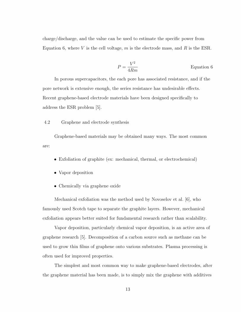
charge/discharge, and the value can be used to estimate the specific power from
Equation 6, where V is the cell voltage, m is the electrode mass, and R is the ESR.
P =V 2
4RmEquation 6
In porous supercapacitors, the each pore has associated resistance, and if the
pore network is extensive enough, the series resistance has undesirable effects.
Recent graphene-based electrode materials have been designed specifically to
address the ESR problem [5].
4.2 Graphene and electrode synthesis
Graphene-based materials may be obtained many ways. The most common
are:
• Exfoliation of graphite (ex: mechanical, thermal, or electrochemical)
• Vapor deposition
• Chemically via graphene oxide
Mechanical exfoliation was the method used by Novoselov et al. [6], who
famously used Scotch tape to separate the graphite layers. However, mechanical
exfoliation appears better suited for fundamental research rather than scalability.
Vapor deposition, particularly chemical vapor deposition, is an active area of
graphene research [5]. Decomposition of a carbon source such as methane can be
used to grow thin films of graphene onto various substrates. Plasma processing is
often used for improved properties.
The simplest and most common way to make graphene-based electrodes, after
the graphene material has been made, is to simply mix the graphene with additives
13
that improve conductivity and binding [4].
4.3 State of the art
Pure electrochemical double-layer capacitors (EDLC) have been found to
support specific capacitances of about 100 - 250 F/g. Pseudocapacitors (PC)
typically have about double the specific capacitance of EDLCs, and there have been
reports of specific capacitances of over 1000 F/g [10]. A summary of some recent
research papers is shown in Table 1. In the table, edlc and pc refer to
electrochemical double-layer capacitors and pseudocapacitors, respectively. It
should be noted that the specific capacitance Cs, of a supercapacitor is only one of
several important performance metrics. Other performance parameters of electrode
materials include cycling stability, volumetric density, voltage range, frequency
response (impedance), among others. Practical considerations for manufacture
include cost, toxicity, and material availability.
Typically, the carbon material to be used in a supercapacitor electrode needs
to be mixed with other additives such as binders and conductivity boosters. For
most researchers working on graphene-based supercapacitor electrodes, this is the
case. The Jang group, for instance, has made promising graphene-based
supercapacitor electrodes by mixing many sheets of graphene with 5 %w Super-P
(conductivity booster) and 10 %w polytetraflouroethylene (PTFE) [4]. The
graphene-based composite is then typically applied to a metallic substrate, which is
known as the current collector. Two such electrodes can then be separated by a
porous membrane such as the Celguard-3501, which is what was used by the Jang
group [4]. Their fabricated cell was estimated to have a specific energy density of
over 80 Wh/kg at room temperature, which is about twice that of an average
14
lead-acid battery and approaching that of a lithium ion battery.
Many laboratory-scale efforts have been made to grow graphene and carbon
nanotubes vertically (perpendicular to the current-collector) in order to achieve high
surface area and low porosity. The active carbon materials grown in this fashion are
significantly different from traditional porous carbon composites, if only for their
relatively low thickness values (ex: < 1 µm) and negligible weights. As such, these
more advanced electrodes can be called thin-film electrodes. In principle, thin-film
supercapacitors using the spiral geometry could outperform commercial devices. A
calculation based on the spiral architecture predicted a capacitance C > 14, 000 F
for a graphene electrode with thickness of 0.6 µm and an overall device length of
13.8 cm [11].
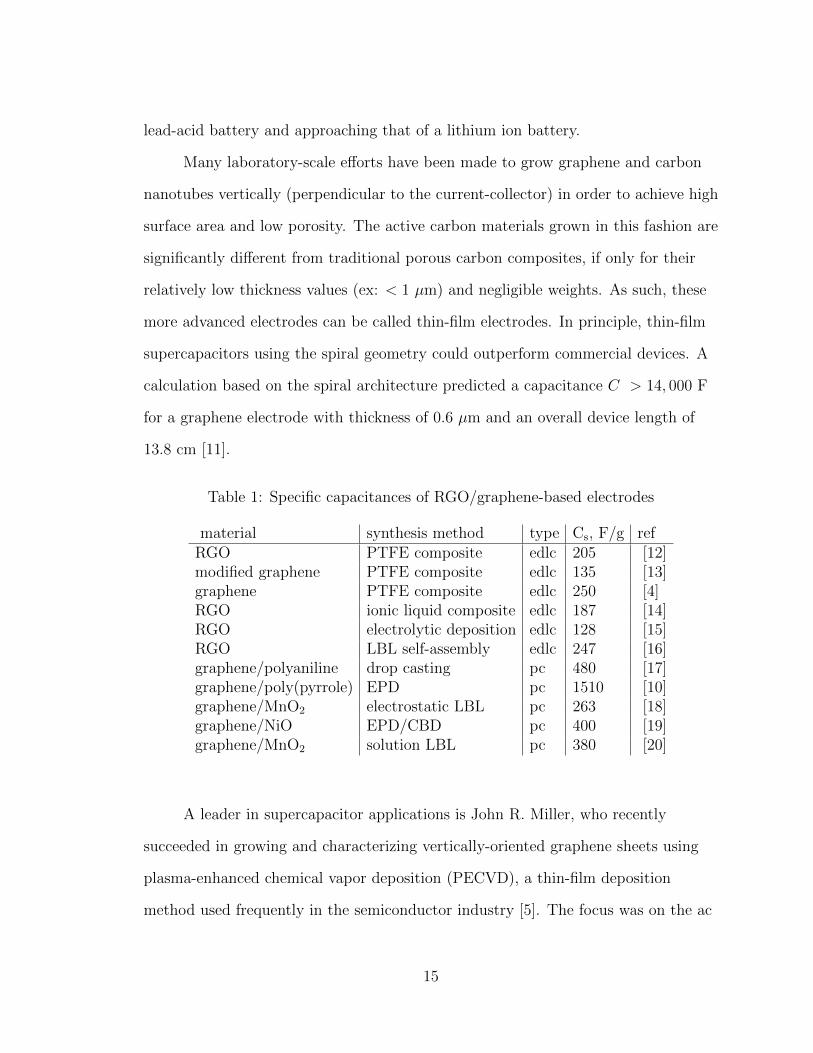
Table 1: Specific capacitances of RGO/graphene-based electrodes
material synthesis method type Cs, F/g refRGO PTFE composite edlc 205 [12]modified graphene PTFE composite edlc 135 [13]graphene PTFE composite edlc 250 [4]RGO ionic liquid composite edlc 187 [14]RGO electrolytic deposition edlc 128 [15]RGO LBL self-assembly edlc 247 [16]graphene/polyaniline drop casting pc 480 [17]graphene/poly(pyrrole) EPD pc 1510 [10]graphene/MnO2 electrostatic LBL pc 263 [18]graphene/NiO EPD/CBD pc 400 [19]graphene/MnO2 solution LBL pc 380 [20]
A leader in supercapacitor applications is John R. Miller, who recently
succeeded in growing and characterizing vertically-oriented graphene sheets using
plasma-enhanced chemical vapor deposition (PECVD), a thin-film deposition
method used frequently in the semiconductor industry [5]. The focus was on the ac
15
impedance behavior, which appeared, via EIS, to have been optimized (low pore
resistance). The target application for such supercapacitors is for ac line filtering.
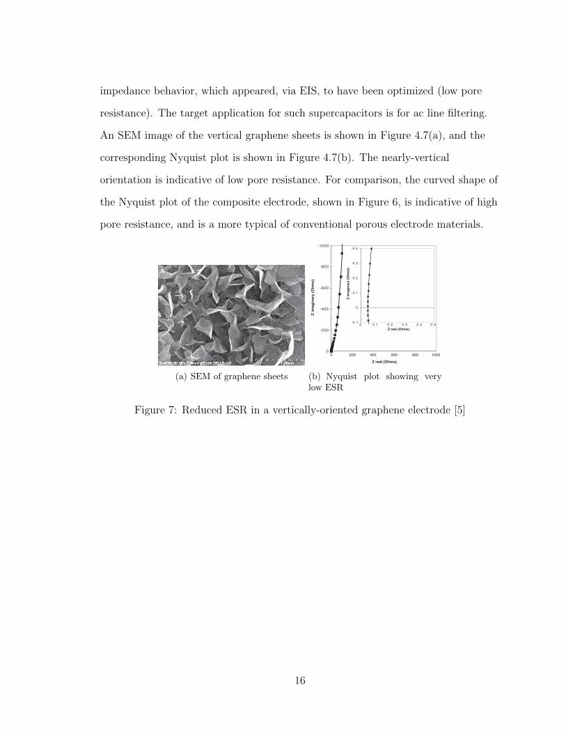
An SEM image of the vertical graphene sheets is shown in Figure 4.7(a), and the
corresponding Nyquist plot is shown in Figure 4.7(b). The nearly-vertical
orientation is indicative of low pore resistance. For comparison, the curved shape of
the Nyquist plot of the composite electrode, shown in Figure 6, is indicative of high
pore resistance, and is a more typical of conventional porous electrode materials.
Graphene Double-Layer Capacitorwith ac Line-Filtering PerformanceJohn R. Miller,1* R. A. Outlaw,2 B. C. Holloway3
Electric double-layer capacitors (DLCs) can have high storage capacity, but their porous electrodescause them to perform like resistors in filter circuits that remove ripple from rectified direct current.We have demonstrated efficient filtering of 120-hertz current with DLCs with electrodes made fromvertically oriented graphene nanosheets grown directly on metal current collectors. This designminimized electronic and ionic resistances and produced capacitors with RC time constants of less than200 microseconds, in contrast with ~1 second for typical DLCs. Graphene nanosheets have apreponderance of exposed edge planes that greatly increases charge storage as compared with that ofdesigns that rely on basal plane surfaces. Capacitors constructed with these electrodes could be smallerthan the low-voltage aluminum electrolyte capacitors that are typically used in electronic devices.
Electric double-layer capacitors (DLCs), al-so called supercapacitors or ultracapaci-tors, store charge in the double layer formed
at an electrolyte-electrode interface when voltageis applied. The electrodes are generally composedof high-surface-area conductive material, usuallyactivated carbon (1). DLCs typically store morethan an order of magnitude more energy per unitvolume than conventional capacitors (2) but, likebatteries, are low-voltage devices, so they oftenmust be connected in series to meet system volt-age requirements. Electric double-layer charge stor-agewas first observedmore than 100 years ago, butDLC products did not reach the market until 1978(3). The introduction of volatile computer memorycreated the need for a power source that could becharged repeatedly and then reliably deliver lowlevels of dc power over a long time. Kilofarad-sized capacitors became available starting in the
mid-1990s to “load-level” the power profile ofbattery-powered electric vehicles that were thenunder development (4) and, more recently, to cap-ture and store energy derived from kinetic energyharvesting—for instance, the braking energy of ahybrid vehicle (5).
The delayed introduction of DLCswas causedby a limited market for capacitors that could onlystore charge but performed poorly at their othermain task: filtering voltage ripple (6). The typicalresistor-capacitor (RC) time constant for a DLCis ~1 s—far too long to be useful for the commonapplication of 120-Hz filtering (8.3 ms period),which entails smoothing the leftover ac ripple ondc voltage busses found in most line-powered elec-tronics. Sixty-Hz ac power is full-wave rectifiedand then filtered to create pure dc voltage. Filteringtoday is performed primarily by means of alumi-num electrolytic capacitors, which usually areamong the largest components found in any elec-tronic circuit: Smaller-sized filtering capacitors mayallow system size reductions, which is particularlyvaluable in some portable electronics applications.
Present DLCs have an impedance phase-angleat 120Hz that is near 0°, which is far from the –90°value needed for filtering. This drawback is a di-rect result of using porous electrodes, which store
charge in a distributed fashion. When driven by120-Hz ac, they respond like a transmission line(7); that is, they behave like a resistor rather thana capacitor. Thus, high-surface-area materials withless inherent porosity have been examined. DLCsfabricated from felt-like electrodes comprising entan-gled, multiwall carbon nanotubes (CNTs) did estab-lish a frequency response record in 1997: 6 Hzfor an impedance phase angle of –45° (8). (Resist-ance and reactance have equal magnitudes at aphase angle of –45°,making this frequency conve-nient for comparison purposes.) These DLCs hadthin electrodes and used a high-conductivity aqueouselectrolyte but were still incapable of filtering at120 Hz for two reasons. First, the felt-like struc-ture created porosity with a pore length equal tothe electrode thickness, thus creating distributedcharge storage with associated ionic resistance.Second, the structure relied onmanifold electricalcontacts among the individual CNTs and againstthe current collector, contributing to the electron-ic resistance. Although these capacitorswere unableto filter, they showed that DLC frequency responsecould be improved by using electrode materialswith external rather than internal surface area.
Further improvements in frequency responsewere reported from electrodes of multiwall CNTsthat were deposited onto ametal current collector,cleared of oxygen surface groups, and bonded tothe collector with a hydrogen furnace treatment(9–11). These capacitors reached a –45° phaseangle at 636 Hz, which is more than 100 timesthe 1997 record. The phase angle at 120 Hz was–65°, and thus they could not efficiently filter atthis frequency.Multi-wall, vertically aligned CNTsgrown directly on a metal current collector werealso investigated as DLC electrodes. One suchstudy showed impedance data with a –45° phaseangle at 443 Hz (12). Yet another study bondedvertically aligned CNTelectrodes to an aluminumcurrent collector, but this also was unable to ef-ficiently filter 120-Hz ripple (13).
Agglomerated, chemically modified graphenematerial was evaluated as a DLC electrode and
1JME, Inc., 17210 Parkland Drive, Shaker Heights, OH 44120,USA, and Case Western Reserve University, Great Lakes EnergyInstitute, Cleveland, OH 44106, USA. 2Department of AppliedScience, College of William and Mary, Williamsburg, VA23185, USA. 3Defense Advanced Research Projects Agency,3701 North Fairfax Drive, Arlington, VA 22203, USA.
*To whom correspondence should be addressed. E-mail:[email protected]
Fig. 1. (A) Plan SEM micrograph of coated Ni electrode. (B) SEM micrograph of a coated fiber, showing plan and shallow-angle views.
REPORTS
www.sciencemag.org SCIENCE VOL 329 24 SEPTEMBER 2010 1637
on
July
25,
201
1w
ww
.sci
ence
mag
.org
Dow
nloa
ded
from
(a) SEM of graphene sheets
showed a considerable degree of unwanted porous-electrode behavior (14). Apparently, direct accessto the charge-storage surfaceswas severely restrictedby the structure, adding substantial ionic resist-ance. Furthermore, the bonded electrode reliedonmultiple electrical contacts among the grapheneagglomerates, similar to the contacts present in allparticulate electrodes, thus contributing additionalelectronic resistance. Capacitors constructed withelectrodes of agglomerated graphene electrode asreported were not capable of 120-Hz filtering.
Electrodes with vertically oriented graphenenanosheets coating carbon fibers have also beenexamined (15). Capacitor designs were devel-oped for a 14,900 F device, but no two-terminalelectrical responses were reported. Such vertical-ly oriented graphene nanosheets are believed tooffer a near-ideal structure for DLC electrodescapable of high-frequency operation. First, theyhave a preponderance of edge planes that providecapacitance of 50 to 70 mF/cm2 in comparisonwith that of basal planes, which provide capaci-tance of only ~3 mF/cm2 (16). Second, charge-storageedge planes are exposed and directly accessible,minimizing the distributed nature of the chargestorage. Third, porosity effects are minimal becauseof the open structure, reducing ionic resistances.And fourth, graphene nanosheets themselves haveextremely high conductivity and can be grown froma conductive surface, minimizing electronic resist-ances. These factors, we expect, should providehigh levels of charge storage that is accessible throughminimum series resistance and thus allow crea-tion of a DLC capable of high-frequency operation.
We synthesized vertically oriented graphenenanosheets directly on heated nickel (Ni) substratesusing radio frequency (RF) plasma–enhancedchemical vapor deposition (17, 18). After pump-down, the substrates were plasma-etched for 10min in 40% argon (Ar) + 60%H2 (total pressureof 50 mT). After the Ar was shut off, the Ni sub-
strate was heated to 1000°C inH2,methane (CH4)was added, and a 1000-W plasma was generatedby using 40%CH4 and 60%H2 at a total pressureof 85mT. Initially, graphitic islands formed on theNi substrate (Volmer-Weber planar growth), withtwo-dimensional growth continuing until impinge-ment with other islands. This basal layer was ap-proximately 10 to 15 nm thick. After 20 min ofgrowth, the resulting coating was composed ofvertically oriented graphitic nanosheets approxi-mately 600 nm high with a cross section <1 nmthick, but often terminating with an edge of agraphene sheet (one atomic layer).
A plan view of vertically oriented graphenenanosheet electrode (Fig. 1A) shows the irregularmorphology of the surface (exposed edge planesand the random expansive open areas) created bydefects that arise from stress and hydrogen in-corporation. The structures grow vertically from themetal substrate and are electronically connectedto it. The measured surface area was ~1100 m2/g.Similar graphene growth is shown in Fig. 1B, buton a circular fiber so as to display both plan andshallow-angle views of the surface. Raman inten-sity measurements of the coating had a D/G bandintensity ratio (ID/IG) of 0.67 because of defects.
Capacitors were fabricated to measure the elec-trical performance of the vertically oriented graphenenanosheet electrodes.Two identical 2.5-cm-diameter,75-mm-thick Ni disks with graphene nanosheetcoatings grown over their 1.6-cm-diameter cen-tral region (2.0 cm2 area)were separated by a 25-mm-thick microporous separator. The coatings and theseparator were wetted with the aqueous electro-lyte [25% potassium hydroxide (KOH)] beforesealing the perimeter of the disks with a thermo-plastic by use of an impulse-heat-seal apparatus.These packaged prototypes, 2.5 cm diameter by~175 mm thick, had a mass of ~0.8 g. The activematerial-coating thickness on each electrode wasapproximately 0.6mm,which is negligible comparedwith device dimensions and mass. Electrical con-nection was made to the back surface of each Nidisk.
Impedance phase angle data of a prototypecapacitor fabricated with the vertically orientedgraphene nanosheet electrodes is shown in Fig. 2.Data from a commercial DLC and from an alu-minum electrolytic capacitor are included for com-parison. All sets of data show capacitive behavior(near –90° phase angle) at low frequency andinductive behavior at high frequency. However,the transition between these two limits occursover a single decade in frequency for the graphenenanosheet capacitor, whereas it occurs over ap-proximately seven decades in frequency for theactivated carbon capacitor. This disparity is duealmost entirely to electrode porosity differences.The impedance phase angle of the graphenenanosheet capacitor reached –45° at ~15,000 Hzin comparison with 0.15 Hz for the activated car-bon capacitor and ~30,000 Hz for the electrolyticcapacitor. At 120 Hz, the impedance phase angleof the graphene nanosheet capacitor was approx-imately –82° as comparedwith ~0° for the activatedcarbon capacitor and approximately –83° for thealuminum electrolytic capacitor. The phase anglefor a blank (bareNi electrode prototype)was –85°.
A complex plane plot of the impedance dataobtained from the vertically oriented graphene nano-sheet capacitor is shown in Fig. 3, with an expandedview in the inset. There is no evidence of porouselectrode behavior, which would manifest itself bya line that intersects the real axis at a near-45° angle.There are also no features associated with a series-passive layer (high-frequency semicircle),whichwouldadd series resistance. Data fit a near-vertical line asproduced by a series-RC circuit. Raistrick modeledthe impedance of rough, saw-tooth-surface elec-trodes having various height-to-separation ratios(19). Fig. 3 follows such rough-surface behaviorwith an aspect ratio of <2, which is consistent withthe observed scanning electronmicroscopy (SEM)micrograph structure.
We used a series-RC circuit model in whichresistance is the real part of the impedance andcapacitance is calculated as C = –1/(2pfZ!),where f is frequency in Hz and Z! is the imag-
Fig. 3. Complex plane plot of theimpedance of the graphene nano-sheet capacitor showing verticalintersection with the real axis andnot the usual porous electrode be-havior shown by DLCs.
-1000
-800
-600
-400
-200
00 200 400 600 800 1000
Z real (Ohms)
Z im
agin
ary
(Ohm
s)
-0.4
-0.3
-0.2
-0.1
0
0 .10 0 .1 0 .2 0 .3 0 .4 0 .5
Z real (Ohms)
Z im
agin
ary
(Ohm
s)
-90
-60
-30
0
30
60
Pha
se a
ngle
(deg
rees
)
Graphene DLCAl electrolyticActivated carbon DLC
9010-3 10-2 10-1
Frequency (Hz)100 101 102 103 104 105
Fig. 2. Impedance phase angle versus frequencyfor the graphene nanosheet DLC. Measurementsfrom a commercial DLC having an activated carbonelectrode and an aluminum electrolytic capacitorare shown for comparison.
24 SEPTEMBER 2010 VOL 329 SCIENCE www.sciencemag.org1638
REPORTS
on
July
25,
201
1w
ww
.sci
ence
mag
.org
Dow
nloa
ded
from
(b) Nyquist plot showing verylow ESR
Figure 7: Reduced ESR in a vertically-oriented graphene electrode [5]
16
CHAPTER 5
CONCLUSION
Graphene-based materials are attractive candidates for supercapacitor
electrodes. Graphene may eventually replace or compliment other carbon materials
as sources of high surface area and therefore high capacitance. More
laboratory-scale capacitor cells need to be assembled and replicated to verify the
technological improvements over cheaper carbon materials, but some laboratory
data have looked promising. Cost effective mass production of single-layer graphene
has not yet been realized, although it may be possible. Nevertheless, few layer
graphene still shows improved performance over other carbon materials, and it is
much easier to obtain. In particular, reduced graphene oxide (RGO) materials are
very easy to make and could be competitive commercially.
Pristine single-layer graphene is usually made with vapor deposition methods,
whereas few-layer RGO is usually made chemically. Once the graphene or composite
material is made, there are many methods to synthesize electrodes, including
pressing, drop-casting, layer-by-layer (LBL) assembly, and electrophoretic deposition
(EPD). Pure electrochemical double layer capacitors made of graphene materials
have specific capacitances up to about 250 F/g. Graphene based pseudocapacitors,
which are composites with polymers or metal oxides, have specific capacitances of
over 400 F/g. Although pseudocapacitors hold more energy than pure EDLCs, they
are unstable in some circumstances. Thin-film electrodes, particularly those with
vertically-oriented sheets, hold promise for future developments. Ionic liquid
electrolytes can be used to extend voltage ranges, and therefore capacitance values.
17
REFERENCES
[1] R. Kotz and M. Carlen, “Principles and applications of electrochemicalcapacitors,” Electrochimica Acta, 45, 2483–2498 (2000).
[2] T. Szabo, O. Berkesi, P. Forgo, K. Josepovits, Y. Sanakis, D. Petridis andI. Dekany, “Evolution of Surface Functional Groups in a Series of ProgressivelyOxidized Graphite Oxides,” Chemistry of Materials, 18, 2740–2749 (2006).
[3] D.R. Dreyer, S. Park, W. Bielawski and R.S. Ruoff, “The chemistry ofgraphene oxide,” Chemical Society Reviews (2010).
[4] C. Liu, Z. Yu, D. Neff, A. Zhamu and B.Z. Jang, “Graphene-BasedSupercapacitor with an Ultrahigh Energy Density,” Nano Letters, 10, 4863–4868(2010).
[5] J.R. Miller, “Graphene Double-Layer Capacitor with ac Line-FilteringPerformance,” Science, 329, 1637–1639 (2010).
[6] K. Novoselov, A.K. Geim, S. Morzov, D. Jiang, Y. Zhang, S. Dubonos,I. Grigorieva and A.A. Firsov, “Electric Field Effect in Atomically Thin CarbonFilms,” Science, 306, 666–669 (2004).
[7] S.J. Wang, Y. Geng, Q. Zheng and J.k. Kim, “Fabrication of highly conductingand transparent graphene films,” Carbon, 48, 1815–1823 (2010).
[8] W.S. Hummers, “Preparation of Graphitic Oxide,” Journal of the AmericanChemical Society, 208, 1339 (1958).
[9] B. Conway,Electrochemical Supercapacitors: scientific fundamentals and technological applications,1st ed. (Kluwer Academic / Plenum Publishers, 1999).
[10] P.A. Mini, A. Balakrishnan, S.V. Nair and K.R.V. Subramanian, “Highly supercapacitive electrodes made of graphene / poly ( pyrrole ),” ChemicalCommunications, 1, 5753–5755 (2011).
[11] X. Zhao, H. Tian, M. Zhu, K. Tian, J.J. Wang, F. Kang and R.A. Outlaw,“Carbon nanosheets as the electrode material in supercapacitors,” Journal ofPower Sources, 194, 1208–1212 (2009).
18
[12] Y. Wang, Z. Shi, Y. Huang, Y. Ma, C. Wang, M. Chen and Y. Chen,“Supercapacitor Devices Based on Graphene Materials,” Journal of PhysicalChemistry C, 113, 13103–13107 (2009).
[13] M.D. Stoller, S. Park, Y. Zhu, J. An and R.S. Ruoff, “Graphene-BasedUltracapacitors,” Nano Letters, 8, 3498–3502 (2008).
[14] T.Y. Kim, H.W. Lee, M. Stoller, D.R. Dreyer, C.W. Bielawski, R.S. Ruoff andK.S. Suh, “High-Performance Supercapacitors,” ACS Nano, XXX (2010).
[15] X.Y. Peng, D. Diamond and K.T. Lau, “Synthesis of electrochemically-reducedgraphene oxide film with controllable size and thickness and its use insupercapacitor,” Carbon, 49, 3488–3496 (2011).
[16] J.J. Yoo, K. Balakrishnan, J. Huang, V. Meunier, B.G. Sumpter, A. Srivastava,M. Conway, A. Leela, M. Reddy, J. Yu, R. Vajtai and P.M. Ajayan, “UltrathinPlanar Graphene Supercapacitors,” Nano Letters, 11, 1423–1427 (2011).
[17] K. Zhang, L.L. Zhang, X.S. Zhao and J. Wu, “Graphene / PolyanilineNanofiber Composites as Supercapacitor Electrodes,” Chemistry of Materials,22, 1392–1401 (2010).
[18] Z. Li, J. Wang, X. Liu, S. Liu, J. Ou and S. Yang, “Electrostatic layer-by-layerself-assembly multilayer films based on graphene and manganese dioxide sheetsas novel electrode materials for supercapacitors,” Journal of MaterialsChemistry, 21, 3397–3403 (2011).
[19] X. Xia, J. Tu, Y. Mai, R. Chen, X. Wang and C. Gu, “Graphene Sheet /Porous NiO Hybrid Film for Supercapacitor Applications,” Chemistry: AEuropean Journal, 00, 1–9 (2011).
[20] G. Yu, L. Hu, N. Liu, H. Wang, M. Vosgueritchian, Y. Yang and Y. Cui,“Enhancing the Supercapacitor Performance of Graphene/MnO2Nanostructured Electrodes by Conductive Wrapping,” Nano Letters, 00, 1–5(2011).
19