Super-precision angular contact ball bearings: 718 (SEA) series
40
Super-precision angular contact ball bearings: 718 (SEA) series
Transcript of Super-precision angular contact ball bearings: 718 (SEA) series

Super-precision angular contact ball bearings: 718 (SEA) series

Contents
A Product information
SKF super-precision angular contact ball bearings in the 718 (SEA) series . . . . . 3
The assortment . . . . . . . . . . . . . . . . . . 4The design . . . . . . . . . . . . . . . . . . . . . . . 4Bearing variants . . . . . . . . . . . . . . . . . . . 4Single bearings and matched bearing sets . . . . . . . . . . . . . . . . . . . . . . 5
Applications . . . . . . . . . . . . . . . . . . . . . 6
B Recommendations
Bearing selection . . . . . . . . . . . . . . . . . 8
Bearing arrangement design . . . . . . . . 9Single bearings . . . . . . . . . . . . . . . . . . . . 9Bearing sets . . . . . . . . . . . . . . . . . . . . . . 9Type of arrangement . . . . . . . . . . . . . . . 10Application examples . . . . . . . . . . . . . . . 12
Lubrication . . . . . . . . . . . . . . . . . . . . . . 14Grease lubrication . . . . . . . . . . . . . . . . . 14Oil lubrication . . . . . . . . . . . . . . . . . . . . . 16
C Product data
Bearing data – general . . . . . . . . . . . . . 17Dimensions . . . . . . . . . . . . . . . . . . . . . . 17Chamfer dimensions . . . . . . . . . . . . . . . 17Tolerances . . . . . . . . . . . . . . . . . . . . . . . 17Bearing preload . . . . . . . . . . . . . . . . . . . 18Bearing axial stiffness . . . . . . . . . . . . . . 22Fitting and clamping of bearing rings . . . 23Load carrying capacity of bearing sets . . 24Equivalent bearing loads . . . . . . . . . . . . 24Attainable speeds . . . . . . . . . . . . . . . . . . 25Cages . . . . . . . . . . . . . . . . . . . . . . . . . . . 25Materials . . . . . . . . . . . . . . . . . . . . . . . . 25Heat treatment . . . . . . . . . . . . . . . . . . . . 25Marking of bearings and bearing sets . . 26Packaging . . . . . . . . . . . . . . . . . . . . . . . . 27Designation system . . . . . . . . . . . . . . . . 27
Product table . . . . . . . . . . . . . . . . . . . . 30
D Additional information
Setting the highest standard for precision bearings . . . . . . . . . . . . . . . . 36Super-precision angular contact ball bearings . . . . . . . . . . . . . . . . . . . . . . . . . 36Super-precision cylindrical roller bearings . . . . . . . . . . . . . . . . . . . . . . . . . 37Super-precision double direction angular contact thrust ball bearings . . . . . . . . . . 37Super-precision angular contact thrust ball bearings for screw drives . . . . . . . . . 37Super-precision axial-radial cylindrical roller bearings . . . . . . . . . . . . . . . . . . . . 37
SKF – the knowledge engineering company . . . . . . . . . . . . . . . . . . . . . . . . 38
2

SKF super-precision angular contact ball bearings in the 718 (SEA) series
Machine tools and other precision applica-tions require superior bearing performance . Extended speed capability, a high degree of running accuracy, high system rigidity, low heat generation, and low noise and vibration levels are just some of the performance challenges .
To meet the ever-increasing performance requirements of precision applications, SKF has developed a new generation of super- precision bearings . The new design super-precision angular contact ball bearings in the 718 (SEA)1) series are characterized by:
high-speed capability•high stiffness•extended fatigue life•easy mounting•compact cross section•
SKF super-precision angular contact ball bearings in the 718 (SEA) series provide optimum performance in applications where there is a need for high reliability and super ior accuracy . The bearings are particularly suit-able for machine tool applications, multi-spindle drilling heads, robotic arms and measuring devices .
1) Where applicable, designations in parentheses and italics refer to the corresponding SNFA equivalent .
A
3

The assortment
The designSKF super-precision single row angular contact ball bearings in the 718 (SEA) ser ies († fig. 1) are characterized by a symmetric inner ring and a non-symmetric outer ring, which enable the bearing to accommodate radial loads, and axial loads in one direction .
Some of the features of bearings in the 718 (SEA) series include:
15° and 25° contact angles•a maximum number of balls•a lightweight phenolic resin cage•an optimized chamfer design•
With two contact angles to choose from, designers can optimize their application based on axial load carrying capacity, speed cap ability and rigidity . Each bearing has the largest possible number of balls to provide the highest possible load carrying capacity .
The outer ring shoulder-guided cage is designed to enable sufficient lubricant to be supplied to the ball/raceway contact areas . The shape of the corner radius of the inner and outer rings († fig. 2) has been opti-mized for improved mounting accuracy . As a result, mounting is not only easier but there is also less risk of damage to associated components .
Bearing variantsBased on the operating conditions in preci-sion applications, bearing requirements can vary . As a result, there are four variants of SKF super-precision angular contact ball bearings in the 718 (SEA) series to choose from .
SKF super-precision angular contact ball bearings in the 718 (SEA) series are avail-able standard as all-steel bearings and hy-brid bearings . Both can accommodate shaft diameters ranging from 10 to 160 mm and are available with two contact angles .
Bearings in the 718 (SEA) series, like all angular contact ball bearings, are nearly always adjusted against a second bearing or used in sets to accommodate axial loads . Bearings suitable for mounting in sets are available in various preload classes . Matched bearing sets with a different preload can be supplied on request .
4

Contact anglesBearings in the 718 (SEA) series are produced as standard with († fig. 3):
a 15° contact angle, •designation suffix CD (1)a 25° contact angle, •designation suffix ACD (3)
Bearings with a 25° contact angle are used primarily in applications requiring high axial rigidity or high axial load carrying capacity .
Ball materialsStandard bearings in the 718 (SEA) series are available with († fig. 4):
steel balls, no designation suffix•ceramic (silicon nitride) balls, designation •suffix HC (/NS)
As ceramic balls are considerably lighter and harder than steel balls, hybrid bearings can provide a higher degree of rigidity and run considerably faster than comparable all-steel bearings . The lower weight of the cer-amic balls reduces the centrifugal forces within the bearing and generates less heat . Lower centrifugal forces are particularly important in machine tool applications where there are frequent rapid starts and stops . Less heat generated by the bearing means less energy consumption and longer lubricant service life .
Single bearings and matched bearing setsSKF super-precision angular contact ball bearings in the 718 (SEA) series are available as:
single, standard bearings•single, universally matchable bearings•matched bearing sets•sets of universally matchable bearings•
15° 25°
Fig. 3
r1
r2
b°
a°
Fig. 2
719718
7072
72719718 70
Series comparisonBearings in the 718 (SEA) series differ from high-precision angular contact ball bearings in other series mainly by their smaller cross section. For a given outside diameter, bearings in the 718 (SEA) series accommodate the largest shaft diameter and together with a larger number of small balls, rigidity is increased.
Fig. 4
Steel balls Ceramic balls
Fig. 1
A
5

Applications
The assortment of SKF super-precision angular contact ball bearings in the 718 (SEA) series offers solutions for a variety of applications . Their ability to provide a high degree of rigidity and accommodate high speeds with extremely low runout can offer a variety of benefits to different applications .
By using the SKF logistics system, the bearings are available worldwide .
ApplicationsMachine tools•Robotics•Printing•Measuring systems•Racing car wheels•
RequirementsHigh positioning accuracy•Reliable positioning repeatability•Low energy consumption•Long service life•Easy mounting•Increased machine uptime•High power density for compact •designs
Solution
6

A
7

Bearing selection
Bearing selection is paramount when deal-ing with applications that require a high degree of accuracy at high speeds . The four variants of SKF super-precision angular contact ball bearings in the 718 (SEA) series are well suited to accommodate the condi-tions dictated by these applications .
The main criteria when selecting bearings in the 718 (SEA) series are:
precision•rigidity•speed•load•
PrecisionWhen dealing with rolling bearings, preci-sion is described by tolerance classes for running and dimensional accuracy .
When selecting bearings in the 718 (SEA) series, the following should be considered:
All bearing variants are manufactured to •P4 (ABEC 7) tolerance class as standard .All bearing variants can be manufactured •to the higher precision P2 (ABEC 9) toler-ance class on request .
RigidityIn precision applications, the rigidity of the bearing arrangement is extremely import-ant, as the magnitude of elastic deformation under load determines the productivity and accuracy of the equipment . Although bear-ing stiffness contributes to system rigidity, there are other influencing factors such as the number and position of the bearings .
When selecting bearings in the 718 (SEA) series, the following should be considered:
Silicon nitride balls provide a higher • degree of stiffness than steel balls .A larger contact angle provides a higher •degree of axial stiffness .Bearings mounted in a back-to-back ar-•rangement provide the highest degree of rigidity .
For matched bearing sets that are • asymmetrical, preload classes A, B or C are preferred .
SpeedHigh-speed applications require cool run-ning, low-friction bearings like angular con-tact ball bearings in the 718 (SEA) series . When selecting bearings in this series, the following should be considered:
In general, bearings lubricated with oil •can operate at higher speeds than grease lubricated bearings .The attainable speeds of oil lubricated •bearings vary, depending on the oil lubri-cation method .Hybrid bearings can operate at higher •speeds than comparably sized all-steel bearings .With a larger contact angle, speed cap-•ability is decreased .For matched bearing sets that are • asymmetrical, preload classes L, M or F are preferred .
LoadIn high-speed precision applications, the load carrying capacity of a bearing is typic-ally less important than in general engineer-ing applications . Angular contact ball bear-ings can accommodate radial and axial loads acting simultaneously . When these com-bined loads exist, the direction of the load also plays an important role in the selection process .
When selecting bearings in the 718 (SEA) series, the following should be considered:
A larger contact angle results in a higher •axial load carrying capacity .The axial load carrying capacity of a bear-•ing arrangement can be increased by adding bearings in tandem .
8

Bearing arrangements can be designed using single bearings or bearing sets . An example of the ordering possibilities for a three bearing arrangement is provided in table 1 on page 10 .
Single bearingsSingle SKF super-precision angular contact ball bearings in the 718 (SEA) series are available as standard bearings or universally matchable bearings . When ordering single bearings, indicate the number of individual bearings required .
Standard bearingsStandard bearings are intended for arrange-ments where only one bearing is used in each bearing position .
Although the widths of the bearing rings in standard bearings are made to very tight tolerances, these bearings are not suitable for mounting immediately adjacent to each other .
Bearing arrangement design
Universally matchable bearings
Universally matchable bearings are specific-ally manufactured so that when mounted in random order, but immediately adjacent to each other, a given preload and/or even load distribution is obtained without the use of shims or similar devices . These bearings can be mounted in random order for any desired bearing arrangement .
Single, universally matchable bearings are available in three preload classes and carry the designation suffix G (U) .
Bearing setsSKF super-precision angular contact ball bearings in the 718 (SEA) series are avail-able as matched bearing sets or as sets of universally matchable bearings . For bearing arrangements that are asymmetrical, matched bearing sets provide a greater number of possibilities for accommodating rigidity and speed requirements .
When ordering bearing sets, indicate the number of bearing sets required (the number of individual bearings per set is specified in the designation) .
Matched bearing setsBearings can be supplied as a complete bearing set consisting typically of two, three or four bearings . The bearings are matched to each other during production so that when mounted immediately adjacent to each other in a specified order, a given preload and/or even load distribution is ob-tained without the use of shims or similar devices . The bore and outside diameters of these bearings are matched to within a maximum of one-third of the applicable permitted diameter tolerance, resulting in an even better load distribution when mounted, compared to single, universally matchable bearings .
Matched bearing sets are available in three preload classes for symmetrical ar-rangements and six preload classes for asymmetrical arrangements .
Sets of universally matchable bearings
The bearings in these sets can be mounted in random order for any desired bearing ar-rangement . The bore and outside diameters of universally matchable bearings in a set are matched to within a maximum of one-third of the applicable permitted diameter tolerance, resulting in an even better load distribution when mounted, compared to single, universally matchable bearings .
Sets of universally matchable bearings are available in three preload classes . Like single, universally matchable bearings, such sets carry the designation suffix G (U) but their positions in the designation differ († table 1, page 10) .
9
B

Type of arrangementUniversally matchable bearings and matched bearing sets can be arranged in various combinations depending on the stiffness and axial load requirements . The possible combinations are shown in fig. 1, including the designation suffixes applicable to matched bearing sets .
Back-to-back bearing arrangement
In a back-to-back bearing arrangement, the load lines diverge toward the bearing axis . Axial loads acting in both directions can be accommodated, but only by one bearing or bearing set in one direction each . Bearings mounted back-to-back provide a relatively rigid bearing arrangement that can also accommodate tilting moments .
Face-to-face bearing arrangement
In a face-to-face bearing arrangement, the load lines converge toward the bearing axis . Axial loads acting in both directions can be accommodated, but only by one bearing or bearing set in one direction each . Face-to-face arrangements are not as rigid as back-to-back arrangements and are less able to accommodate tilting moments .
Tandem bearing arrangementIn a tandem bearing arrangement, the load lines are parallel so that radial and axial loads are shared equally by the bearings in the set . The bearing set can only accommo-date axial loads acting in one direction . If axial loads act in the opposite direction, or if combined loads are present, additional bearing(s) adjusted against the tandem arrangement should be added .
Table 1
Example of the ordering possibilities for a three bearing arrangement with light preload
Design criteria What to order Designation1) Order example
Bearing arrangement is not known Three single, universally matchable bearings
718 . .DG . ./P4 . .(SEA ..7 CE..U..)
3 ¥ 71810 CDGA/P4(3 ¥ SEA50 7CE1 UL)
Bearing arrangement is not known and improved load distribution is desirable
A set of three universally matchable bearings
718 . .D/P4TG . .(SEA ..7 CE..TU..)
1 ¥ 71810 CD/P4TGA(1 ¥ SEA50 7CE1 TUL)
Bearing arrangement is known and high rigidity is required
Three bearings in a matched set 718 . .D/P4T . .(SEA ..7 CE..T..)
1 ¥ 71810 CD/P4TBTA(1 ¥ SEA50 7CE1 TD14,4DaN)
Bearing arrangement is known and high speed is required
Three bearings in a matched set 718 . .D/P4T . .(SEA ..7 CE..T..)
1 ¥ 71810 CD/P4TBTL(1 ¥ SEA50 7CE1 TDL)
1) For additional information about designations, refer to table 15 on pages 28 and 29 .
10

Fig. 1
Bearing sets with 2 bearings
Back-to-back arrangement Face-to-face arrangement Tandem arrangement Designation suffix DB (DD) Designation suffix DF (FF) Designation suffix DT (T)
Bearing sets with 3 bearings
Back-to-back and tandem arrangement Face-to-face and tandem arrangement Tandem arrangementDesignation suffix TBT (TD) Designation suffix TFT (TF) Designation suffix TT (3T)
Bearing sets with 4 bearings
Tandem back-to-back arrangement Tandem face-to-face arrangementDesignation suffix QBC (TDT) Designation suffix QFC (TFT)
Back-to-back and tandem arrangement Face-to-face and tandem arrangement Tandem arrangementDesignation suffix QBT (3TD) Designation suffix QFT (3TF) Designation suffix QT (4T)
11
B

Tool holder sleeveWhen space is limited and the loads are relatively light, two matched bearing sets of super-precision angular contact ball bearing pairs, e.g. 71801 ACD/P4DBB (SEA12 7CE3 DDM), are suitable.
Multispindle drilling headFor multispindle drilling heads, where radial space is limited and axial rigidity is very important, super-precision angular contact ball bearings matched in a set of four bearings (arranged back-to-back and tandem), e.g. 71802 ACD/P4QBTA (SEA15 7CE3 3TD27,2DaN), incorporating a set of precision-matched spacer rings, can be used.
Application examplesSuper-precision angular contact ball bear-ings are common in, but not limited to, ma-chine tool applications . Depending on the type of machine tool and its intended pur-pose, spindles may have different require-ments regarding bearing arrangements . Lathe spindles, for example, are typically used to cut metals at relatively low speeds . Depth of cut and feed rates are usually pushed to the limit . A high degree of rigidity and high load carrying capacity are import-ant operational requirements .
When higher speeds are demanded, as is the case for high-speed machining centres, milling operations and grinding applications, there is typically a compromise between rigidity and load carrying capacity . In these high-speed applications, controlling the heat generated by the bearings is an additional challenge .
For any precision application, there is an optimal arrangement to provide the best possible combination of rigidity, load carry-ing capacity, heat generation and bearing service life .
12

Grinding workheadIn a grinding workhead, where rigidity is import-ant and available space limited, a set of two super-precision angular contact ball bearings, e.g. 71824 ACD/P4DBB (SEA120 7CE3 DDM), are suitable.
Lathe spindleFor lathe spindles with large bar diameter capacities, super- precision angular contact ball bearings matched as a set of five bearings, e.g. 71818 ACD/P4PBCB (SEA90 7CE3 3TDT45DaN), incorp-orating a set of preci-sion-matched spacer rings, providing good rigidity, are used.
13
B

Lubrication
The choice of the lubricant and lubrication method for a particular application depends primarily on the operating conditions, such as permissible temperature or speed, but may also be dictated by the lubrication of adjacent components e .g . gear wheels .
For an adequate lubricant film to be formed between the balls and raceways, only a very small amount of lubricant is re-quired . Therefore, grease lubrication for precision bearing arrangements is becoming increasingly popular . With grease lubrica-tion, the hydrodynamic friction losses are small and operating temperatures can be kept to a minimum . However, where speeds are very high, the bearings should be lubri-cated with oil as the service life of grease is too short under such conditions and oil provides the added benefit of cooling .
Grease lubricationIn most applications with super-precision angular contact ball bearings, grease with a mineral base oil and lithium thickener is suit-able . These greases adhere well to the bear-ing surfaces and can be used where tempera-tures range from –30 to +100 °C . For bearing
arrangements that run at very high speeds and temperatures, and where long service life is required, the use of grease based on syn-thetic oil, e .g . the diester oil based grease SKF LGLT 2, has been proven effective .
Initial grease fillIn high-speed applications, less than 30% of the free space in the bearings should be filled with grease . The initial grease fill de-pends on the bearing size as well as the speed factor, which is
A = n dm
whereA = speed factor [mm/min]n = rotational speed [r/min]dm = bearing mean diameter
= 0,5 (d + D) [mm]
The initial grease fill can be estimated from
G = K Gref
1) Refers to a 30% filling grade .
Table 1
Reference grease quantity for initial grease fill estimation
Bearing ReferenceBore Size grease diameter quantity1)
d Gref
mm – cm3
10 00 0,0612 01 0,0715 02 0,0817 03 0,09
20 04 0,1825 05 0,2130 06 0,2435 07 0,28
40 08 0,3145 09 0,3650 10 0,555 11 0,88
60 12 1,265 13 1,370 14 1,475 15 1,5
80 16 1,685 17 2,790 18 2,995 19 3,1
100 20 3,2105 21 4110 22 5,1120 24 5,5
130 26 9,3140 28 9,9150 30 13160 32 14
1,1
1,0
0,9
0,8
0,7
0,6
0,5
0,4
0,3
0,2
0,1
00 0,2 0,4 0,6 0,8 1,0 1,2 1,4
Speed factor A [106 mm/min]
Factor K
Diagram 1
Factor K for initial grease fill estimation
whereG = initial grease fill [cm3]K = a calculation factor dependent
on the speed factor A († diagram 1)Gref = reference grease quantity
(† table 1) [cm3]
14

Running-in of grease lubricated bearings
A grease lubricated super-precision bearing in the 718 (SEA) series will initially run with a relatively high frictional moment . If the bearing is run at high speed without a run-ning-in period, the temperature rise can be considerable . The relatively high frictional moment is due to the churning of the grease and it takes time for the excess grease to work its way out of the contact zone . This time period can be min imized by applying a small quantity of grease distributed evenly on both sides of the bearing during the as-sembly stage . Spacers between two adja-cent bearings are also beneficial († Indi-vidual adjustment of preload using spacer rings, page 20) .
The time required to stabilize the oper-ating temperature depends on a number of factors – the type of grease, the initial grease fill, how the grease is applied to the bearings and the running-in procedure († diagram 2) .
Super-precision bearings typically can operate with minimal lubricant quantity when properly run-in, enabling the lowest frictional moment and temperature to be
achieved . The grease that collects at the sides of the bearing will act as a reservoir and the oil will bleed into the raceways to provide efficient lubrication for a long time .
Running-in can be done in several ways . Wherever possible and regardless of the procedure chosen, running-in should in-volve operating the bearing in both a clock-wise and anticlockwise direction .
The standard running-in procedure can be summarized as follows:
Select a low starting speed and a rela-1 tively small speed increment interval .Decide on an absolute temperature limit, 2 usually 60 to 65 °C . It is advisable to set the equipment with limit switches that will stop the equipment if the temperature rise exceeds the set limit .Start operation at the chosen initial 3 speed .Monitor the temperature by taking meas-4 urements at the bearing outer ring pos-ition, avoiding peaks, and wait for it to stabilize . If the temperature reaches the limit, stop operation and allow the bear-ing to cool . Start again at the same speed and wait for the temperature to stabilize .
Increase the speed by one interval and 5 repeat step 4 .Continue increasing the speed in inter-6 vals, allowing the temperature to stabilize below the limit at each stage . Proceed until this is achieved for one speed inter-val greater than the operating speed of the system . This results in a lower temp-erature rise during normal operation . The bearing is now properly run-in .
The standard running-in procedure is nor-mally time-consuming and the total time for the running-in process could be as high as 8 to 10 hours .
The short running-in procedure reduces the number of stages . Although each stage may have to be repeated several times, each cycle is just a few minutes long, and the total time for this running-in process is substan-tially less than the standard procedure .
Diagram 2
Graphic representation of a running-in procedure
Time [h]
Temperature [°C] Speed [r/min]
60
20 0
Operating speed of the system
Absolute temperature limit
Operating temperatureSpeed
10–15 min . forstabilized temperature
† Stage 1 † Stage 2 † Stage 3 † Stage 4 † Stage 5
15
B

Table 2
Oil nozzle positions for oil-air lubrication
Bearing Oil nozzle Bore Size positiondiameterd dn
mm – mm
10 00 13,412 01 15,415 02 18,417 03 20,4
20 04 24,525 05 29,530 06 34,535 07 39,5
40 08 44,545 09 50,050 10 55,655 11 61,3
60 12 66,465 13 72,470 14 77,475 15 82,4
80 16 87,485 17 94,190 18 99,195 19 104,1
100 20 109,1105 21 114,6110 22 120,9120 24 130,9
130 26 144,0140 28 153,2150 30 165,6160 32 175,6
dnd
The main steps of the short running-in procedure can be summarized as follows:
Select a starting speed approximately 1 20 to 25% of the attainable speed and choose a relatively large speed increment interval . Decide on an absolute temperature limit, 2 usually 60 to 65 °C . It is advisable to set the equipment with limit switches that will stop the equipment if the temperature rise exceeds the limits set .Start operation at the chosen initial 3 speed .Monitor the temperature by taking meas-4 urements at the bearing outer ring pos-ition until the temperature reaches the limit . Care should be taken as the tem-perature increase may be very rapid .Stop operation and let the outer ring of 5 the bearing cool down by 5 to 10 °C .Start operation at the same speed a se-6 cond time and monitor the temperature until the limit is reached again .Repeat 7 steps 5 and 6 until the tempera-ture stabilizes below the limit . When the temperature peak is lower than the alarm limit, the bearing is run-in at that particu-lar speed .Increase the speed by one interval and 8 repeat steps 4 to 7 .Proceed until the bearing is running at 9 one speed interval higher than the oper-ating speed of the system . This results in a lower temperature rise during normal operation . The bearing is now properly run-in .
Oil lubricationOil lubrication is recommended for many applications, as the method of supply can be adapted to suit the operating conditions and design of the equipment .
Oil-air lubrication methodFor typical arrangements with bearings in the 718 (SEA) series, the high operational speeds and requisite low operating tempera-tures generally require an oil-air lubrication system . With the oil-air method, also called the oil-spot method, accurately metered quantities of oil are directed at each individ-ual bearing by compressed air . For bearings used in sets, each bearing is supplied by a separate oil injector . Most designs include spacers that incorporate the oil nozzles .
Guidelines for the quantity of oil to be supplied to each bearing for high-speed operation can be obtained from
Q = 1,3 dm
whereQ = oil flow rate [mm3/h]dm = bearing mean diameter
= 0,5 (d + D) [mm]
The calculated oil flow rate should be veri-fied during operation and adjusted depend-ing on the resulting temperatures .
Oil is supplied to the feed lines at given inter vals by a metering unit . The oil coats the inside surface of the feed lines and “creeps” toward the nozzles, where it is de-livered to the bearings . The oil nozzles should be pos itioned correctly († table 2) to make sure that the oil can be introduced into the contact area between the balls and raceways and to avoid interference with the cage .
High quality lubricating oils without EP additives are generally recommended for super-precision angular contact ball bearings . Oils with a viscosity of 40 to 100 mm2/s at 40 °C are typically used . A filter that prevents particles > 5 μm from reaching the bearings should also be incorporated .
16

Bearing data – general
DimensionsThe boundary dimensions of SKF super-precision angular contact ball bearings in the 718 (SEA) series for dimension series 18 are in accordance with ISO 15:2011 .
Table 1
Class P4 (ABEC 7) tolerances
Inner ringd Δdmp Δds Vdp Vdmp ΔBs ΔB1s VBs Kia Sd Siaover incl . high low high low max max high low high low max max max max
mm μm μm μm μm μm μm μm μm μm μm
2,5 10 0 –4 0 –4 4 2 0 –40 0 –250 2,5 2,5 3 310 18 0 –4 0 –4 4 2 0 –80 0 –250 2,5 2,5 3 318 30 0 –5 0 –5 5 2,5 0 –120 0 –250 2,5 3 4 430 50 0 –6 0 –6 6 3 0 –120 0 –250 3 4 4 4
50 80 0 –7 0 –7 7 3,5 0 –150 0 –250 4 4 5 580 120 0 –8 0 –8 8 4 0 –200 0 –380 4 5 5 5120 150 0 –10 0 –10 10 5 0 –250 0 –380 5 6 6 7150 180 0 –10 0 –10 10 5 0 –250 0 –380 5 6 6 7
Outer ringD ΔDmp ΔDs VDp VDmp ΔCs ΔC1s VCs Kea SD Seaover incl . high low high low max max high low high low max max max max
mm μm μm μm μm μm μm μm μm μm μm
18 30 0 –5 0 –5 5 2,5 0 –120 0 –250 2,5 4 4 530 50 0 –6 0 –6 6 3 0 –120 0 –250 2,5 5 4 550 80 0 –7 0 –7 7 3,5 0 –150 0 –250 3 5 4 580 120 0 –8 0 –8 8 4 0 –200 0 –380 4 6 5 6
120 150 0 –9 0 –9 9 5 0 –250 0 –380 5 7 5 7150 180 0 –10 0 –10 10 5 0 –250 0 –380 5 8 5 8180 250 0 –11 0 –11 11 6 0 –300 0 –500 7 10 7 10
Chamfer dimensionsMinimum values for the chamfer dimensions in the radial direction (r1, r3) and the axial direction (r2, r4) are provided in the product tables . The values for the chamfers of the inner ring and thrust side of the outer ring are in accordance with ISO 15:2011; the values for the non-thrust side of the outer ring are not standardized .
The appropriate maximum chamfer limits are in accordance with ISO 582:1995 .
TolerancesSKF super-precision angular contact ball bearings in the 718 (SEA) series are made to P4 tolerance class, in accordance with ISO 492:2002, as standard . On request, bearings can be supplied to the higher precision P2 tolerance class .
The tolerance values are listed as follows:
P4 (ABEC 7) tolerance class in • table 1P2 (ABEC 9) tolerance class in • table 2 on page 18
C
17

Table 2
Class P2 (ABEC 9) tolerances
Inner ringd Δdmp Δds Vdp Vdmp ΔBs ΔB1s VBs Kia Sd Siaover incl . high low high low max max high low high low max max max max
mm μm μm μm μm μm μm μm μm μm μm
2,5 10 0 –2,5 0 –2,5 2,5 1,5 0 –40 0 –250 1,5 1,5 1,5 1,510 18 0 –2,5 0 –2,5 2,5 1,5 0 –80 0 –250 1,5 1,5 1,5 1,518 30 0 –2,5 0 –2,5 2,5 1,5 0 –120 0 –250 1,5 2,5 1,5 2,530 50 0 –2,5 0 –2,5 2,5 1,5 0 –120 0 –250 1,5 2,5 1,5 2,5
50 80 0 –4 0 –4 4 2 0 –150 0 –250 1,5 2,5 1,5 2,580 120 0 –5 0 –5 5 2,5 0 –200 0 –380 2,5 2,5 2,5 2,5120 150 0 –7 0 –7 7 3,5 0 –250 0 –380 2,5 2,5 2,5 2,5150 180 0 –7 0 –7 7 3,5 0 –250 0 –380 4 5 4 5
Outer ringD ΔDmp ΔDs VDp VDmp ΔCs ΔC1s VCs Kea SD Seaover incl . high low high low max max high low high low max max max max
mm μm μm μm μm μm μm μm μm μm μm
18 30 0 –4 0 –4 4 2 0 –120 0 –250 1,5 2,5 1,5 2,530 50 0 –4 0 –4 4 2 0 –120 0 –250 1,5 2,5 1,5 2,550 80 0 –4 0 –4 4 2 0 –150 0 –250 1,5 4 1,5 480 120 0 –5 0 –5 5 2,5 0 –200 0 –380 2,5 5 2,5 5
120 150 0 –5 0 –5 5 2,5 0 –250 0 –380 2,5 5 2,5 5150 180 0 –7 0 –7 7 3,5 0 –250 0 –380 2,5 5 2,5 5180 250 0 –8 0 –8 8 4 0 –350 0 –500 4 7 4 7
Bearing preloadPreload in bearings prior to mounting
To meet the varying requirements regarding rotational speed and rigidity, bearings in the 718 (SEA) series are produced to different preload classes . In applications where a high degree of rigidity is more important than a high operational speed, the following preload classes are available:
class A, light preload•class B, moderate preload•class C, heavy preload•
These preload classes are valid for:
single, universally matchable bearings•sets of universally matchable bearings•all matched bearing sets•
The preload level depends on the contact angle, the inner geometry and the size of the bearing and applies to bearing sets with two bearings arranged back-to-back or face-to-face as listed in table 3 .
Bearing sets consisting of three or four bearings, and preloaded according to preload classes A, B and C, have a heavier preload than sets with two bearings . The preload for these bearing sets is obtained by multiplying the values listed in table 3 by a factor of:
1,35 for TBT • (TD) and TFT (TF) arrangements1,6 for QBT • (3TD) and QFT (3TF) arrangements2 for QBC • (TDT) and QFC (TFT) arrangements
In applications where a high operational speed is more important than a high degree of rigidity, the following additional preload classes are available:
class L, reduced light preload for • asymmetrical bearing setsclass M, reduced moderate preload •for asymmetrical bearing setsclass F, reduced heavy preload for • asymmetrical bearing sets
These preload classes are only available for matched bearing sets that are asymmetrical i .e . for TBT (TD), TFT (TF), QBT (3TD) and QFT (3TF) arrangements . In these cases, due to the higher speed capability and lower degree of rigidity, matched bearing sets consisting of three or four bearings have the same preload as sets with two bearings of similar preload class . The preload for matched bearing sets that are asymmetrical for TBT (TD), TFT (TF), QBT (3TD) and QFT (3TF) arrangements can therefore be ob-tained from table 3 .
Bearing sets with a special preload can be supplied on request . These bearing sets are identified by the designation suffix G fol-lowed by a number . The number is the mean preload value of the set expressed in daN . Special preload is not applicable for sets of universally matchable bearings con-sisting of three or more bearings (suffixes TG and QG) .
18

Preload in mounted bearing sets
Universally matchable bearings and matched bearing sets have a heavier preload when mounted than when un-mounted . The increase in preload depends mainly on:
the actual tolerances for the bearing seats •on the shaft and in the housing borethe rotational speed of the shaft, if the •bearings are pressed against each other
An increase in preload can, among other things, also be caused by:
temperature differences between the • inner ring, outer ring and ballsdifferent coefficient of thermal expansion •for the shaft and housing materialsdeviations from the geometrical form of •associated components such as cylindric-ity, perpendicularity or concentricity of the bearing seats
If the bearings are mounted with the usual fits (js4 shaft tolerance and JS5 housing bore tolerance for bearings manufactured to P4 tolerance class) on a steel shaft and in a thick-walled steel or cast iron housing, preload can be determined with sufficient accuracy from
Gm = f f1 f2 fHC GA,B,C
whereGm = preload in the mounted bearing set
[N]GA,B,C = preload in the bearing set prior to
mounting († table 3) [N]f = a bearing factor dependent on
the bearing size († table 4, page 20)
f1 = a correction factor dependent on the contact angle († table 5, page 20)
f2 = a correction factor dependent on the preload class († table 5, page 20)
fHC = a correction factor for hybrid bearings († table 5, page 20)
Considerably tighter fits may be necessary, for example for very high speed spindles, where the centrifugal forces can loosen the inner ring from its seat on the shaft . These bearing arrangements must be carefully evaluated .
Table 3
Axial preload of single, universally matchable bearings and matched bearing pairs prior to mounting, arranged back-to-back or face-to-face
Bearing Axial preloadBore Size of bearings in the seriesdiameter 718 ACD (SEA CE3) 718 CD (SEA CE1)
718 ACD/HC (SEA /NS CE3) 718 CD/HC (SEA /NS CE1)for preload class for preload class
d A B C A B C
mm – N
10 00 16 48 100 10 30 6012 01 17 53 105 11 33 6615 02 19 58 115 12 36 7217 03 20 60 120 12 37 75
20 04 32 100 200 20 60 12025 05 35 105 210 22 66 13230 06 37 110 220 23 70 14035 07 39 115 230 25 75 150
40 08 40 120 240 26 78 15545 09 41 125 250 27 80 16050 10 60 180 360 40 120 24055 11 87 260 520 55 165 330
60 12 114 340 680 70 210 42065 13 115 345 690 71 215 43070 14 117 350 700 73 220 44075 15 120 360 720 76 225 450
80 16 123 370 740 78 235 47085 17 183 550 1 100 115 345 69090 18 184 555 1 110 116 350 70095 19 186 560 1 120 117 355 710
100 20 190 570 1 140 120 360 720105 21 200 600 1 200 130 390 780110 22 260 800 1 600 160 500 1 000120 24 280 850 1 700 180 550 1 100
130 26 325 980 1960 210 620 1 230140 28 380 1 140 2 280 240 720 1 440150 30 430 1 300 2 590 270 820 1 630160 32 450 1 350 2 690 280 850 1 700
C
19

Table 5
Correction factors for calculating the preload in mounted bearing sets
Bearing series Correction factorsf1 f2 fHC
for preload class A B C
718 CD (SEA CE1) 1 1 1,09 1,16 1
718 ACD (SEA CE3) 0,97 1 1,08 1,15 1
718 CD/HC (SEA /NS CE1) 1 1 1,10 1,18 1,02
718 ACD/HC (SEA /NS CE3) 0,97 1 1,09 1,17 1,02
Fig. 1
Preload with constant forceIn precision, high-speed applications, a con-stant and uniform preload is important . To maintain the proper preload, calibrated lin-ear springs can be used between one bear-ing outer ring and its housing shoulder († fig. 1) . With springs, the kinematic be-haviour of the bearing will not influence preload under normal operating conditions . Note, however, that a spring loaded bearing arrangement has a lower degree of rigidity than an arrangement using axial displace-ment to set the preload .
Preload by axial displacementRigidity and precise axial guidance are crit-ical parameters in bearing arrangements, especially when alternating axial forces occur . In these cases, the preload in the bearings is usually obtained by adjusting the bearing rings relative to each other in the axial direction . This preload method offers significant benefits in terms of system rigid-ity . However, depending on the bearing type and ball material, preload increases consid-erably with rotational speed .
Universally matchable bearings and matched bearing sets are manufactured to specifications so that when mounted properly they will attain their predetermined axial displacement and consequently the proper preload . With single standard bear-ings, precision-matched spacer rings must be used .
Individual adjustment of preload using spacer rings
It may be necessary to optimize the preload of a bearing set for certain operating condi-tions . By using spacer rings between the bearings, it is possible to increase or de-crease preload . The use of spacer rings in angular contact ball bearing sets is also advantageous when:
system rigidity should be increased•nozzles for oil-air lubrication must be as •close as possible to the bearing racewayssufficiently large space is needed for • surplus grease in order to reduce heat generated by the bearings
By grinding the side face of the inner or outer spacer ring, the preload in the bearing set can be changed .
Table 6 provides information about which of the equal-width spacer ring side faces must be ground and what effect it will have . Guideline values for the requisite overall width reduction of the spacer rings are listed in table 7 .
To achieve maximum bearing perform-ance, the spacer rings must not deform under load . They should be made of high-grade steel that can be hardened to between 45 and 60 HRC . Particular importance must be given to the plane parallelism of the side face surfaces, where the permissible shape deviation must not exceed 1 to 2 μm .
Table 4
Bearing factor f for calculating the preload in mounted bearing sets
Bearing Bearing factor fBore diameter
Size
d
mm – –
10 00 1,0512 01 1,0615 02 1,0817 03 1,10
20 04 1,0825 05 1,1130 06 1,1435 07 1,18
40 08 1,2345 09 1,2450 10 1,3055 11 1,27
60 12 1,3065 13 1,2870 14 1,3275 15 1,36
80 16 1,4185 17 1,3190 18 1,3395 19 1,36
100 20 1,40105 21 1,44110 22 1,34120 24 1,41
130 26 1,34140 28 1,43150 30 1,37160 32 1,42
20

Table 7
Guideline values for spacer ring width reduction
Bearing Requisite spacer ring width reductionBore Size for bearings in the seriesdiameter 718 ACD (SEA CE3) 718 CD (SEA CE1)d a b a b
mm – μm
10 00 4 4 5 512 01 4 4 5 515 02 4 4 5 517 03 4 4 5 5
20 04 4 5 6 625 05 4 5 6 630 06 4 5 6 635 07 4 5 6 6
40 08 4 5 6 645 09 4 5 6 650 10 5 6 8 855 11 6 7 9 9
60 12 7 8 10 1165 13 7 8 10 1170 14 7 8 10 1175 15 7 8 10 11
80 16 7 8 10 1185 17 9 10 13 1390 18 9 10 13 1495 19 9 10 13 14
100 20 9 10 13 14105 21 9 10 14 14110 22 10 12 16 16120 24 11 12 16 17
130 26 11 12 16 17140 28 12 14 18 20150 30 13 14 19 20160 32 13 15 19 20
a, b
a, b a, b
a, b
Table 6
Guidelines for spacer ring modification
Bearing set Width reduction Requisite spacer ringPreload change Value between bearings arranged back-to-back face-to-face
Increasing the preloadfrom A to B a inner outerfrom B to C b inner outerfrom A to C a + b inner outer
Decreasing the preloadfrom B to A a outer innerfrom C to B b outer innerfrom C to A a + b outer inner
C
21

Bearing axial stiffnessAxial stiffness depends on the deformation of the bearing under load and can be ex-pressed as the ratio of the load to the bear-ing resilience . However, since the resilience of rolling bearings does not depend linearly on the load, axial stiffness is also load- dependent . Exact values of axial stiffness for bearings in the 718 (SEA) series for a given load can be calculated using advanced com-puter methods, but guideline values are list-ed in table 8 . These values apply to mount-ed bearing sets under static conditions with two all-steel bearings arranged back-to-back or face-to-face and subjected to moderate loads .
Bearing sets comprising three or four bearings can provide a higher degree of axial stiffness than sets with two bearings . The axial stiffness for these sets can be cal-culated by multiplying the values listed in table 8 by a factor dependent on the bear-ing arrangement and preload class of the bearings . For bearing sets produced to preload classes A, B or C, the following factors apply:
1,45 for TBT • (TD) and TFT (TF) arrangements1,8 for QBT • (3TD) and QFT (3TF) arrangements2 for QBC • (TDT) and QFC (TFT) arrangements
Matched bearing sets that are asymmetrical can be produced to the additional preload classes L, M or F († Preload in bearings prior to mounting, page 18) . The axial stiff-ness for these bearing sets can be calculated by multiplying the values listed in table 8 by the following factors:
1,25 for TBT • (TD) and TFT (TF) arrangements1,45 for QBT • (3TD) and QFT (3TF) arrangements
For hybrid bearings, the axial stiffness can be calculated in the same way as for all-steel bearings . However, the calculated value should then be multiplied by a factor of 1,11 (for all arrangements and preload classes) .
Table 8
Static axial stiffness for two bearings arranged back-to-back or face-to-face
Bearing Axial stiffnessBore Size of bearings in the seriesdiameter 718 ACD (SEA CE3) 718 CD (SEA CE1)d for preload class for preload class
A B C A B C
mm – N/μm
10 00 30 47 65 13 22 3212 01 34 54 72 15 25 3715 02 40 63 85 17 30 4317 03 43 67 90 18 31 45
20 04 52 83 112 22 38 5525 05 60 95 128 26 44 6430 06 69 106 144 29 49 7235 07 76 119 161 32 56 82
40 08 83 130 178 36 61 9045 09 87 139 189 38 65 9550 10 107 168 231 47 81 11955 11 124 195 268 53 91 135
60 12 141 222 306 59 103 15265 13 144 227 312 61 105 15570 14 152 241 332 65 112 16675 15 162 257 355 69 119 177
80 16 171 274 379 74 128 19185 17 189 296 406 79 137 20290 18 194 307 420 82 142 21095 19 200 316 436 85 147 218
100 20 211 335 462 90 156 231105 21 220 353 488 96 167 250110 22 236 377 518 99 173 256120 24 262 417 576 112 196 291
130 26 278 439 603 119 202 296140 28 306 489 675 130 226 336150 30 323 512 702 136 236 346160 32 352 556 764 147 256 379
22

Fitting and clamping of bearing ringsBearings are typically located axially on shafts or in housings with either precision lock nuts († fig. 2) or end caps . These compo n ents require high geometrical preci-sion and good mechanical strength to pro-vide reliable locking .
The tightening torque Mt, obtained by tightening the precision lock nut or bolts in the end cap, must prevent relative move-ment of adjacent components, provide cor-rect bearing positioning without deform-ation, and minimize material fatigue .
Calculating the tightening torque Mt
It is difficult to accurately calculate the tight-ening torque Mt . The following formulas can be used as guidelines, but should be verified during operation .
The axial clamping force for a precision lock nut or the bolts in an end cap is
Pa = Fs + (NcpFc) + G
The tightening torque for a precision lock nut is
Mt = K Pa = K [Fs + (NcpFc) + G]
The tightening torque for the bolts in an end cap is
K PaMt = ––––– Nb
K [Fs + (NcpFc) + G]Mt = ––––––––––––––––– Nb
whereMt = tightening torque [Nmm]Pa = axial clamping force [N]Fs = minimum axial clamping force
(† table 9) [N]Fc = axial fitting force († table 9) [N]G = bearing preload prior to mounting
(† table 3, page 19) [N]Ncp = the number of preloaded bearingsNb = the number of bolts in the end capK = a calculation factor dependent on the
thread († table 10)
Table 10
Factor K for tightening torque calculation
Nominal thread Factor Kdiameter1) for
precision lock nuts
bolts in end caps
mm –
4 – 0,85 – 1,06 – 1,28 – 1,6
10 1,4 2,012 1,6 2,414 1,9 2,715 2,0 2,9
16 2,1 3,117 2,2 –20 2,6 –25 3,2 –
30 3,9 –35 4,5 –40 5,1 –45 5,8 –
50 6,4 –55 7,0 –60 7,6 –65 8,1 –
70 9,0 –75 9,6 –80 10,0 –85 11,0 –
90 11,0 –95 12,0 –100 12,0 –105 13,0 –
110 14,0 –120 15,0 –130 16,0 –140 17,0 –
150 18,0 –160 19,0 –
1) Applicable for fine threads only .
Table 9
Minimum axial clamping force and axial fitting force for precision lock nuts and end caps
Bearing Minimum Axial Bore Size axial fittingdiameter clamping force
forced Fs Fc
mm – N
10 00 370 24012 01 430 21015 02 550 18017 03 600 160
20 04 950 25025 05 1 200 21030 06 1 400 18035 07 1 600 210
40 08 1 800 18045 09 2 400 19050 10 2 900 18055 11 3 300 230
60 12 3 300 24065 13 4 700 26070 14 5 000 24075 15 5 500 230
80 16 5 500 30085 17 7 500 55090 18 8 000 50095 19 8 000 480
100 20 8 500 460105 21 9 000 450110 22 11 000 600120 24 12 000 600
130 26 17 000 900140 28 16 000 800150 30 21 000 1 000160 32 23 000 1 000
Fig. 2
C
23

Table 12
Calculation factors for single bearings and bearings paired in tandem
f0Fa/C0 Calculation factors
e X Y Y0
For 15° contact angledesignation suffix CD (1)
≤ 0,178 0,38 0,44 1,47 0,460,357 0,40 0,44 1,40 0,460,714 0,43 0,44 1,30 0,461,07 0,46 0,44 1,23 0,46
1,43 0,47 0,44 1,19 0,462,14 0,50 0,44 1,12 0,463,57 0,55 0,44 1,02 0,46≥ 5,35 0,56 0,44 1,00 0,46
For 25° contact angledesignation suffix ACD (3)– 0,68 0,41 0,87 0,38
Load carrying capacity of bearing setsThe values listed in the product tables for the basic dynamic load rating C, the basic static load rating C0 and the fatigue load limit Pu apply to single bearings . For bearing sets, the values for single bearings should be multiplied by a calculation factor accord-ing to the values listed in table 11 .
Equivalent bearing loadsWhen determining the equivalent bearing load for preloaded bearings in the 718 (SEA) series, the preload must be taken into ac-count . Depending on the operating condi-tions, the requisite axial component of the bearing load Fa for a bearing pair arranged back-to-back or face-to-face can be deter-mined approximately from the following equations .
For bearing pairs under radial load and mounted with an interference fit
Fa = Gm
For bearing pairs under radial load and preloaded by springs
Fa = GA,B,C
For bearing pairs under axial load and mounted with an interference fit
Fa = Gm + 0,67 Ka for Ka ≤ 3 GmFa = Ka for Ka > 3 Gm
For bearing pairs under axial load and preloaded by springs
Fa = GA,B,C + Ka
whereFa = axial component of the load [N]GA,B,C = preload of a bearing pair prior to
mounting († table 3, page 19) [N]Gm = preload in the mounted bearing pair
(† Preload in mounted bearing sets, page 19) [N]
Ka = external axial force acting on a single bearing [N]
Table 11
Calculation factors for load carrying capacities of bearing sets
Number Calculation factor of bearings for C C0 Pu
2 1,62 2 2
3 2,16 3 3
4 2,64 4 4
Equivalent dynamic bearing load
For single bearings and bearings paired in tandem
P = Fr for Fa/Fr ≤ eP = XFr + YFa for Fa/Fr > e
For bearing pairs, arranged back-to-back or face-to-face
P = Fr + Y1Fa for Fa/Fr ≤ eP = XFr + Y2Fa for Fa/Fr > e
whereP = equivalent dynamic load of
the bearing set [kN]Fr = radial component of the load acting
on the bearing set [kN]Fa = axial component of the load acting
on the bearing set [kN]
The values for the calculation factors e, X, Y, Y1 and Y2 depend on the bearing contact angle and are listed in tables 12 and 13 . For bearings with a 15° contact angle, the fac-tors also depend on the relationship f0Fa/C0 where f0 and C0 are the calculation factor and basic static load rating respectively, list-ed in the product table .
Equivalent static bearing loadFor single bearings and bearings paired in tandem
P0 = 0,5 Fr + Y0Fa
For bearing pairs, arranged back-to-back or face-to-face
P0 = Fr + Y0Fa
whereP0 = equivalent static load of the bearing set
[kN]Fr = radial component of the load acting
on the bearing set [kN]Fa = axial component of the load acting
on the bearing set [kN]
If P0 < Fr , P0 = Fr should be used . The values for the calculation factor Y0 depend on the bearing contact angle and are listed in tables 12 and 13 .
24

Table 14
Speed reduction factors for bearing sets
Number Arrangement Designation suffix Speed reduction factorof bearings for preload class A L B M C F
2 Back-to-back DB (DD) 0,80 – 0,65 – 0,40 –
Face-to-face DF (FF) 0,77 – 0,61 – 0,36 –
3 Back-to-back and tandem TBT (TD) 0,69 0,72 0,49 0,58 0,25 0,36Face-to-face and tandem TFT (TF) 0,63 0,66 0,42 0,49 0,17 0,24
4 Tandem back-to-back QBC (TDT) 0,64 – 0,53 – 0,32 –Tandem face-to-face QFC (TFT) 0,62 – 0,48 – 0,27 –
Fig. 3Table 13
Calculation factors for bearing pairs arranged back-to-back or face-to-face
2 f0Fa/C0 Calculation factors
e X Y1 Y2 Y0
For 15° contact angledesignation suffix CD (1)
≤ 0,178 0,38 0,72 1,65 2,39 0,920,357 0,40 0,72 1,57 2,28 0,920,714 0,43 0,72 1,46 2,11 0,921,07 0,46 0,72 1,38 2,00 0,92
1,43 0,47 0,72 1,34 1,93 0,922,14 0,50 0,72 1,26 1,82 0,923,57 0,55 0,72 1,14 1,66 0,92≥ 5,35 0,56 0,72 1,12 1,63 0,92
For 25° contact angle designation suffix ACD (3)– 0,68 0,67 0,92 1,41 0,76
Attainable speedsThe attainable speeds listed in the product tables should be regarded as guideline values . They are valid for single bearings under light load (P ≤ 0,05 C) that are lightly preloaded using springs . In addition, good heat dissipation from the bearing arrange-ment is a prerequisite .
The values provided for oil lubrication apply to the oil-air lubrication method and should be reduced if other oil lubrication methods are used . The values provided for grease lubrication are maximum values that can be attained with good lubricating grease that has a low consistency and low viscosity .
If single bearings are adjusted against each other with heavier preload or if bearing sets are used, the attainable speeds listed in
the product tables should be reduced i .e . the values should be multiplied by a reduction factor . Values for this reduction factor, which depend on the bearing arrangement and preload class, are listed in table 14 .
If the rotational speed obtained is not suf-ficient for the application, spacer rings in the bearing set can be used to significantly in-crease the speed capability .
CagesSKF super-precision angular contact ball bearings in the 718 (SEA) series have a one-piece outer ring shoulder-guided cage made of fabric reinforced phenolic resin († fig. 3) that can be used up to 120 °C .
MaterialsThe rings and balls of all-steel angular con-tact ball bearings in the 718 (SEA) series are made from SKF Grade 3 steel, in accordance with ISO 683-17:1999 . Balls of hybrid bearings are made of bearing grade silicon nitride Si3N4 .
Heat treatmentAll SKF super-precision angular contact ball bearings in the 718 (SEA) series undergo a special heat treatment to achieve a good balance between hardness and dimensional stability . The hardness of the rings and rolling elements is optimized for low wear .
Note: for spring-loaded tandem sets, designation suffix DT (T), a speed reduction factor of 0,9 should be applied .
C
25

Marking of bearings and bearing setsEach SKF super-precision angular contact ball bearing in the 718 (SEA) series has various identifiers on the external surfaces of the rings († fig. 4):
SKF trademark1 Complete designation of the bearing2 Country of manufacture3 Date of manufacture, coded4 Deviation of the mean outside diameter 5 ΔDm [μm], and position of the maximum eccentricity of the outer ringDeviation of the mean bore diameter 6 Δdm [μm], and position of the maximum eccentricity of the inner ringThrust face mark (punched)7 Serial number (bearing sets only)8 “V-shaped” marking (matched bearing 9 sets only)
Fa
Fig. 5“V-shaped” markingThe additional identifier on bearings in matched bearing sets provides important information about the mounting sequence and load direction . This identifier, a “V-shaped” marking, is evident on the outside diameter of the outer rings and extends across all of the bearings in the matched bearing set († fig. 5) .
The “V-shaped” marking coincides with the position of maximum ring wall thickness . The marking indicates how the bearings should be mounted to obtain the proper preload and it also points in the direction in which the main axial component of the load Fa will act on the inner rings .
Fig. 4
1
5
7
9
4
86
2
3
26

PackagingSKF super-precision bearings are distrib-uted in new SKF illustrated boxes († fig. 6) . The box contains an instruction sheet with information about mounting bearing sets .
Designation systemThe designation system for SKF super- precision angular contact ball bearings in the 718 (SEA) series is provided in table 15 on pages 28 and 29 together with the definitions .
Fig. 6
C
27
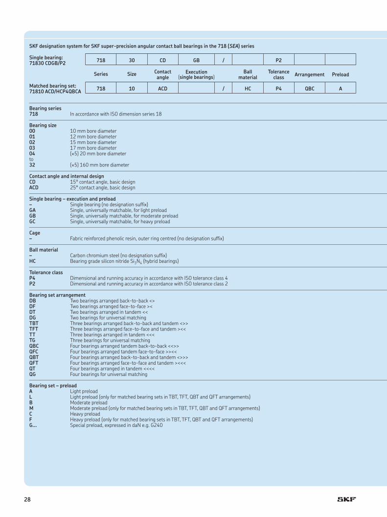
Table 15
SKF designation system for SKF super-precision angular contact ball bearings in the 718 (SEA) series Former SNFA designation system for super-precision angular contact ball bearings in the 718 (SEA) series
Single bearing: 71830 CDGB/P2 718 30 CD GB / P2 Single bearing:
SEA150 9CE1 UM SEA 150 9 CE 1 U M
Contact angle
Execution(single bearings)
Ballmaterial
Tolerance class Arrangement Preload Ball
material Tolerance
classContact angle
Series Size Series Size Cage Arrangement Preload
Matched bearing set: 71810 ACD/HCP4QBCA 718 10 ACD / HC P4 QBC A Matched bearing set:
SEA50 /NS 7CE3 TDTL SEA 50 /NS 7 CE 3 TDT L
Bearing series Bearing series 718 In accordance with ISO dimension series 18 SEA In accordance with ISO dimension series 18
Bearing size Bearing size 00 10 mm bore diameter 10 10 mm bore diameter01 12 mm bore diameter to02 15 mm bore diameter 160 160 mm bore diameter03 17 mm bore diameter04 (¥5) 20 mm bore diameterto32 (¥5) 160 mm bore diameter
Contact angle and internal design Contact angle and internal designCD 15° contact angle, basic design 1 15° contact angle, basic designACD 25° contact angle, basic design 3 25° contact angle, basic design
Single bearing – execution and preload Single bearing– Single bearing (no designation suffix) – Standard (no designation suffix)GA Single, universally matchable, for light preload U_ Universally matchable with preload classGB Single, universally matchable, for moderate preloadGC Single, universally matchable, for heavy preload
Cage Cage– Fabric reinforced phenolic resin, outer ring centred (no designation suffix) CE Fabric reinforced phenolic resin, outer ring centred
Ball material Ball material – Carbon chromium steel (no designation suffix) – Carbon chromium steel (no designation suffix)HC Bearing grade silicon nitride Si3N4 (hybrid bearings) /NS Bearing grade silicon nitride Si3N4 (hybrid bearings)
Tolerance class Tolerance class P4 Dimensional and running accuracy in accordance with ISO tolerance class 4 7 Dimensional and running accuracy in accordance with ABMA tolerance class ABEC 7P2 Dimensional and running accuracy in accordance with ISO tolerance class 2 9 Dimensional and running accuracy in accordance with ABMA tolerance class ABEC 9
Bearing set arrangement Bearing set arrangementDB Two bearings arranged back-to-back <> DD Two bearings arranged back-to-back <>DF Two bearings arranged face-to-face >< FF Two bearings arranged face-to-face ><DT Two bearings arranged in tandem << T Two bearings arranged in tandem <<DG Two bearings for universal matching DU Two bearings for universal matchingTBT Three bearings arranged back-to-back and tandem <>> TD Three bearings arranged back-to-back and tandem <>>TFT Three bearings arranged face-to-face and tandem ><< TF Three bearings arranged face-to-face and tandem ><<TT Three bearings arranged in tandem <<< 3T Three bearings arranged in tandem <<<TG Three bearings for universal matching TU Three bearings for universal matchingQBC Four bearings arranged tandem back-to-back <<>> TDT Four bearings arranged tandem back-to-back <<>>QFC Four bearings arranged tandem face-to-face >><< TFT Four bearings arranged tandem face-to-face >><<QBT Four bearings arranged back-to-back and tandem <>>> 3TD Four bearings arranged back-to-back and tandem <>>>QFT Four bearings arranged face-to-face and tandem ><<< 3TF Four bearings arranged face-to-face and tandem ><<<QT Four bearings arranged in tandem <<<< 4T Four bearings arranged in tandem <<<<QG Four bearings for universal matching 4U Four bearings for universal matching
Bearing set – preload Bearing set – preload A Light preload L Light preloadL Light preload (only for matched bearing sets in TBT, TFT, QBT and QFT arrangements) M Moderate preloadB Moderate preload F Heavy preloadM Moderate preload (only for matched bearing sets in TBT, TFT, QBT and QFT arrangements) ..daN Special preload C Heavy preload F Heavy preload (only for matched bearing sets in TBT, TFT, QBT and QFT arrangements)G... Special preload, expressed in daN e .g . G240
28

Table 15
SKF designation system for SKF super-precision angular contact ball bearings in the 718 (SEA) series Former SNFA designation system for super-precision angular contact ball bearings in the 718 (SEA) series
Single bearing: 71830 CDGB/P2 718 30 CD GB / P2 Single bearing:
SEA150 9CE1 UM SEA 150 9 CE 1 U M
Contact angle
Execution(single bearings)
Ballmaterial
Tolerance class Arrangement Preload Ball
material Tolerance
classContact angle
Series Size Series Size Cage Arrangement Preload
Matched bearing set: 71810 ACD/HCP4QBCA 718 10 ACD / HC P4 QBC A Matched bearing set:
SEA50 /NS 7CE3 TDTL SEA 50 /NS 7 CE 3 TDT L
Bearing series Bearing series 718 In accordance with ISO dimension series 18 SEA In accordance with ISO dimension series 18
Bearing size Bearing size 00 10 mm bore diameter 10 10 mm bore diameter01 12 mm bore diameter to02 15 mm bore diameter 160 160 mm bore diameter03 17 mm bore diameter04 (¥5) 20 mm bore diameterto32 (¥5) 160 mm bore diameter
Contact angle and internal design Contact angle and internal designCD 15° contact angle, basic design 1 15° contact angle, basic designACD 25° contact angle, basic design 3 25° contact angle, basic design
Single bearing – execution and preload Single bearing– Single bearing (no designation suffix) – Standard (no designation suffix)GA Single, universally matchable, for light preload U_ Universally matchable with preload classGB Single, universally matchable, for moderate preloadGC Single, universally matchable, for heavy preload
Cage Cage– Fabric reinforced phenolic resin, outer ring centred (no designation suffix) CE Fabric reinforced phenolic resin, outer ring centred
Ball material Ball material – Carbon chromium steel (no designation suffix) – Carbon chromium steel (no designation suffix)HC Bearing grade silicon nitride Si3N4 (hybrid bearings) /NS Bearing grade silicon nitride Si3N4 (hybrid bearings)
Tolerance class Tolerance class P4 Dimensional and running accuracy in accordance with ISO tolerance class 4 7 Dimensional and running accuracy in accordance with ABMA tolerance class ABEC 7P2 Dimensional and running accuracy in accordance with ISO tolerance class 2 9 Dimensional and running accuracy in accordance with ABMA tolerance class ABEC 9
Bearing set arrangement Bearing set arrangementDB Two bearings arranged back-to-back <> DD Two bearings arranged back-to-back <>DF Two bearings arranged face-to-face >< FF Two bearings arranged face-to-face ><DT Two bearings arranged in tandem << T Two bearings arranged in tandem <<DG Two bearings for universal matching DU Two bearings for universal matchingTBT Three bearings arranged back-to-back and tandem <>> TD Three bearings arranged back-to-back and tandem <>>TFT Three bearings arranged face-to-face and tandem ><< TF Three bearings arranged face-to-face and tandem ><<TT Three bearings arranged in tandem <<< 3T Three bearings arranged in tandem <<<TG Three bearings for universal matching TU Three bearings for universal matchingQBC Four bearings arranged tandem back-to-back <<>> TDT Four bearings arranged tandem back-to-back <<>>QFC Four bearings arranged tandem face-to-face >><< TFT Four bearings arranged tandem face-to-face >><<QBT Four bearings arranged back-to-back and tandem <>>> 3TD Four bearings arranged back-to-back and tandem <>>>QFT Four bearings arranged face-to-face and tandem ><<< 3TF Four bearings arranged face-to-face and tandem ><<<QT Four bearings arranged in tandem <<<< 4T Four bearings arranged in tandem <<<<QG Four bearings for universal matching 4U Four bearings for universal matching
Bearing set – preload Bearing set – preload A Light preload L Light preloadL Light preload (only for matched bearing sets in TBT, TFT, QBT and QFT arrangements) M Moderate preloadB Moderate preload F Heavy preloadM Moderate preload (only for matched bearing sets in TBT, TFT, QBT and QFT arrangements) ..daN Special preload C Heavy preload F Heavy preload (only for matched bearing sets in TBT, TFT, QBT and QFT arrangements)G... Special preload, expressed in daN e .g . G240
C
29

d1
r1
r1
r3
r1
r4r2
r2r2
D1D d
a
B
Principal dimensions Basic load ratings Fatigue load limit
Attainable speeds Mass Designationsdynamic static when lubricating with SKF SNFA
grease oil-aird D B C C0 Pu
mm kN kN r/min kg –
10 19 5 1,9 0,98 0,043 80 000 120 000 0,005 71800 CD/P4 SEA10 7CE119 5 1,78 0,93 0,04 70 000 110 000 0,005 71800 ACD/P4 SEA10 7CE319 5 1,9 0,98 0,043 95 000 150 000 0,005 71800 CD/HCP4 SEA10 /NS 7CE119 5 1,78 0,93 0,04 85 000 130 000 0,005 71800 ACD/HCP4 SEA10 /NS 7CE3
12 21 5 2,08 1,18 0,05 70 000 110 000 0,006 71801 CD/P4 SEA12 7CE121 5 1,95 1,12 0,048 63 000 95 000 0,006 71801 ACD/P4 SEA12 7CE321 5 2,08 1,18 0,05 85 000 130 000 0,006 71801 CD/HCP4 SEA12 /NS 7CE121 5 1,95 1,12 0,048 75 000 110 000 0,006 71801 ACD/HCP4 SEA12 /NS 7CE3
15 24 5 2,29 1,5 0,063 60 000 90 000 0,007 71802 CD/P4 SEA15 7CE124 5 2,16 1,4 0,06 53 000 80 000 0,007 71802 ACD/P4 SEA15 7CE324 5 2,29 1,5 0,063 70 000 110 000 0,006 71802 CD/HCP4 SEA15 /NS 7CE124 5 2,16 1,4 0,06 63 000 100 000 0,006 71802 ACD/HCP4 SEA15 /NS 7CE3
17 26 5 2,34 1,6 0,068 53 000 85 000 0,01 71803 CD/P4 SEA17 7CE126 5 2,21 1,53 0,064 48 000 75 000 0,01 71803 ACD/P4 SEA17 7CE326 5 2,34 1,6 0,068 63 000 100 000 0,009 71803 CD/HCP4 SEA17 /NS 7CE126 5 2,21 1,53 0,064 60 000 90 000 0,009 71803 ACD/HCP4 SEA17 /NS 7CE3
20 32 7 3,9 2,65 0,112 45 000 70 000 0,018 71804 CD/P4 SEA20 7CE132 7 3,64 2,5 0,106 40 000 63 000 0,018 71804 ACD/P4 SEA20 7CE332 7 3,9 2,65 0,112 53 000 80 000 0,017 71804 CD/HCP4 SEA20 /NS 7CE132 7 3,64 2,5 0,106 48 000 75 000 0,017 71804 ACD/HCP4 SEA20 /NS 7CE3
25 37 7 4,16 3,2 0,137 38 000 56 000 0,021 71805 CD/P4 SEA25 7CE137 7 3,9 3,05 0,129 34 000 53 000 0,021 71805 ACD/P4 SEA25 7CE337 7 4,16 3,2 0,137 45 000 70 000 0,019 71805 CD/HCP4 SEA25 /NS 7CE137 7 3,9 3,05 0,129 40 000 63 000 0,019 71805 ACD/HCP4 SEA25 /NS 7CE3
30 42 7 4,42 3,75 0,16 32 000 50 000 0,026 71806 CD/P4 SEA30 7CE142 7 4,16 3,55 0,15 28 000 45 000 0,026 71806 ACD/P4 SEA30 7CE342 7 4,42 3,75 0,16 38 000 60 000 0,024 71806 CD/HCP4 SEA30 /NS 7CE142 7 4,16 3,55 0,15 34 000 53 000 0,024 71806 ACD/HCP4 SEA30 /NS 7CE3
35 47 7 4,62 4,3 0,183 28 000 43 000 0,028 71807 CD/P4 SEA35 7CE147 7 4,36 4,05 0,173 26 000 40 000 0,028 71807 ACD/P4 SEA35 7CE347 7 4,62 4,3 0,183 34 000 53 000 0,026 71807 CD/HCP4 SEA35 /NS 7CE147 7 4,36 4,05 0,173 30 000 48 000 0,026 71807 ACD/HCP4 SEA35 /NS 7CE3
40 52 7 4,88 4,9 0,208 26 000 38 000 0,031 71808 CD/P4 SEA40 7CE152 7 4,49 4,55 0,196 22 000 34 000 0,031 71808 ACD/P4 SEA40 7CE352 7 4,88 4,9 0,208 30 000 45 000 0,029 71808 CD/HCP4 SEA40 /NS 7CE152 7 4,49 4,55 0,196 28 000 43 000 0,029 71808 ACD/HCP4 SEA40 /NS 7CE3
45 58 7 4,88 5,3 0,224 22 000 34 000 0,039 71809 CD/P4 SEA45 7CE158 7 4,62 5 0,212 20 000 30 000 0,039 71809 ACD/P4 SEA45 7CE358 7 4,88 5,3 0,224 26 000 40 000 0,037 71809 CD/HCP4 SEA45 /NS 7CE158 7 4,62 5 0,212 24 000 38 000 0,037 71809 ACD/HCP4 SEA45 /NS 7CE3
Super-precision angular contact ball bearings in the 718 (SEA) seriesd 10 – 45 mm
30

Db
ra
ra
dadbDa
rb
ra
Dimensions Abutment and fillet dimensions Calculation factor
d d1 D1 r1,2 r3,4 a da, db Da Db ra rb f0~ ~ min min min max max max max
mm mm –
10 13,1 16,1 0,3 0,15 4,5 12 17 18,2 0,3 0,15 1513,1 16,1 0,3 0,15 5,9 12 17 18,2 0,3 0,15 –13,1 16,1 0,3 0,15 4,5 12 17 18,2 0,3 0,15 1513,1 16,1 0,3 0,15 5,9 12 17 18,2 0,3 0,15 –
12 15,1 18,1 0,3 0,15 4,7 14 19 20,2 0,3 0,15 1515,1 18,1 0,3 0,15 6,4 14 19 20,2 0,3 0,15 –15,1 18,1 0,3 0,15 4,7 14 19 20,2 0,3 0,15 1515,1 18,1 0,3 0,15 6,4 14 19 20,2 0,3 0,15 –
15 18,1 21,1 0,3 0,15 5,1 17 22 23,2 0,3 0,15 1618,1 21,1 0,3 0,15 7,1 17 22 23,2 0,3 0,15 –18,1 21,1 0,3 0,15 5,1 17 22 23,2 0,3 0,15 1618,1 21,1 0,3 0,15 7,1 17 22 23,2 0,3 0,15 –
17 20,1 23 0,3 0,15 5,4 19 24 25,2 0,3 0,15 1620,1 23 0,3 0,15 7,5 19 24 25,2 0,3 0,15 –20,1 23 0,3 0,15 5,4 19 24 25,2 0,3 0,15 1620,1 23 0,3 0,15 7,5 19 24 25,2 0,3 0,15 –
20 24,1 28,1 0,3 0,15 7 22 30 31,2 0,3 0,15 1624,1 28,1 0,3 0,15 9,6 22 30 31,2 0,3 0,15 –24,1 28,1 0,3 0,15 7 22 30 31,2 0,3 0,15 1624,1 28,1 0,3 0,15 9,6 22 30 31,2 0,3 0,15 –
25 29,1 33,1 0,3 0,15 7,7 27 35 36,2 0,3 0,15 1629,1 33,1 0,3 0,15 10,8 27 35 36,2 0,3 0,15 –29,1 33,1 0,3 0,15 7,7 27 35 36,2 0,3 0,15 1629,1 33,1 0,3 0,15 10,8 27 35 36,2 0,3 0,15 –
30 34,1 38,1 0,3 0,15 8,3 32 40 41,2 0,3 0,15 1734,1 38,1 0,3 0,15 11,9 32 40 41,2 0,3 0,15 –34,1 38,1 0,3 0,15 8,3 32 40 41,2 0,3 0,15 1734,1 38,1 0,3 0,15 11,9 32 40 41,2 0,3 0,15 –
35 39,1 43,1 0,3 0,15 9 37 45 46,2 0,3 0,15 1739,1 43,1 0,3 0,15 13,1 37 45 46,2 0,3 0,15 –39,1 43,1 0,3 0,15 9 37 45 46,2 0,3 0,15 1739,1 43,1 0,3 0,15 13,1 37 45 46,2 0,3 0,15 –
40 44,1 48,1 0,3 0,15 9,7 42 50 51,2 0,3 0,15 1744,1 48,1 0,3 0,15 14,3 42 50 51,2 0,3 0,15 –44,1 48,1 0,3 0,15 9,7 42 50 51,2 0,3 0,15 1744,1 48,1 0,3 0,15 14,3 42 50 51,2 0,3 0,15 –
45 49,6 53,6 0,3 0,15 10,4 47 56 57,2 0,3 0,15 1749,6 53,6 0,3 0,15 15,5 47 56 57,2 0,3 0,15 –49,6 53,6 0,3 0,15 10,4 47 56 57,2 0,3 0,15 1749,6 53,6 0,3 0,15 15,5 47 56 57,2 0,3 0,15 –
31
C

Super-precision angular contact ball bearings in the 718 (SEA) seriesd 50 – 95 mm
Principal dimensions Basic load ratings Fatigue load limit
Attainable speeds Mass Designationsdynamic static when lubricating with SKF SNFA
grease oil-aird D B C C0 Pu
mm kN kN r/min kg –
50 65 7 7,41 7,8 0,335 20 000 30 000 0,051 71810 CD/P4 SEA50 7CE165 7 6,89 7,35 0,315 18 000 28 000 0,051 71810 ACD/P4 SEA50 7CE365 7 7,41 7,8 0,335 24 000 36 000 0,046 71810 CD/HCP4 SEA50 /NS 7CE165 7 6,89 7,35 0,315 22 000 34 000 0,046 71810 ACD/HCP4 SEA50 /NS 7CE3
55 72 9 10,1 10,8 0,455 18 000 28 000 0,081 71811 CD/P4 SEA55 7CE172 9 9,56 10,2 0,43 16 000 24 000 0,081 71811 ACD/P4 SEA55 7CE372 9 10,1 10,8 0,455 22 000 32 000 0,073 71811 CD/HCP4 SEA55 /NS 7CE172 9 9,56 10,2 0,43 19 000 30 000 0,073 71811 ACD/HCP4 SEA55 /NS 7CE3
60 78 10 13,5 14,3 0,6 16 000 24 000 0,1 71812 CD/P4 SEA60 7CE178 10 12,7 13,4 0,57 15 000 22 000 0,1 71812 ACD/P4 SEA60 7CE378 10 13,5 14,3 0,6 19 000 30 000 0,088 71812 CD/HCP4 SEA60 /NS 7CE178 10 12,7 13,4 0,57 18 000 26 000 0,088 71812 ACD/HCP4 SEA60 /NS 7CE3
65 85 10 13,5 14,6 0,63 15 000 22 000 0,126 71813 CD/P4 SEA65 7CE185 10 12,7 14 0,585 13 000 20 000 0,126 71813 ACD/P4 SEA65 7CE385 10 13,5 14,6 0,63 18 000 28 000 0,114 71813 CD/HCP4 SEA65 /NS 7CE185 10 12,7 14 0,585 16 000 24 000 0,114 71813 ACD/HCP4 SEA65 /NS 7CE3
70 90 10 13,8 16 0,67 14 000 22 000 0,134 71814 CD/P4 SEA70 7CE190 10 13 15 0,64 13 000 19 000 0,134 71814 ACD/P4 SEA70 7CE390 10 13,8 16 0,67 17 000 26 000 0,121 71814 CD/HCP4 SEA70 /NS 7CE190 10 13 15 0,64 15 000 24 000 0,121 71814 ACD/HCP4 SEA70 /NS 7CE3
75 95 10 14,3 17 0,72 13 000 20 000 0,142 71815 CD/P4 SEA75 7CE195 10 13,3 16 0,68 12 000 18 000 0,142 71815 ACD/P4 SEA75 7CE395 10 14,3 17 0,72 16 000 24 000 0,128 71815 CD/HCP4 SEA75 /NS 7CE195 10 13,3 16 0,68 14 000 22 000 0,128 71815 ACD/HCP4 SEA75 /NS 7CE3
80 100 10 14,6 18,3 0,765 12 000 19 000 0,151 71816 CD/P4 SEA80 7CE1100 10 13,8 17 0,72 11 000 17 000 0,151 71816 ACD/P4 SEA80 7CE3100 10 14,6 18,3 0,765 15 000 22 000 0,136 71816 CD/HCP4 SEA80 /NS 7CE1100 10 13,8 17 0,72 13 000 20 000 0,136 71816 ACD/HCP4 SEA80 /NS 7CE3
85 110 13 21,6 25,5 1,08 11 000 17 000 0,266 71817 CD/P4 SEA85 7CE1110 13 20,3 24 1,02 10 000 16 000 0,266 71817 ACD/P4 SEA85 7CE3110 13 21,6 25,5 1,08 14 000 20 000 0,239 71817 CD/HCP4 SEA85 /NS 7CE1110 13 20,3 24 1,02 12 000 19 000 0,239 71817 ACD/HCP4 SEA85 /NS 7CE3
90 115 13 21,6 26,5 1,1 11 000 17 000 0,279 71818 CD/P4 SEA90 7CE1115 13 20,3 25 1,04 10 000 15 000 0,279 71818 ACD/P4 SEA90 7CE3115 13 21,6 26,5 1,1 13 000 20 000 0,251 71818 CD/HCP4 SEA90 /NS 7CE1115 13 20,3 25 1,04 12 000 18 000 0,251 71818 ACD/HCP4 SEA90 /NS 7CE3
95 120 13 22,1 27,5 1,12 10 000 16 000 0,292 71819 CD/P4 SEA95 7CE1120 13 20,8 25,5 1,06 9 500 14 000 0,292 71819 ACD/P4 SEA95 7CE3120 13 22,1 27,5 1,12 12 000 19 000 0,263 71819 CD/HCP4 SEA95 /NS 7CE1120 13 20,8 25,5 1,06 11 000 17 000 0,263 71819 ACD/HCP4 SEA95 /NS 7CE3
d1
r1
r1
r3
r1
r4r2
r2r2
D1D d
a
B
32

Dimensions Abutment and fillet dimensions Calculation factor
d d1 D1 r1,2 r3,4 a da, db Da Db ra rb f0~ ~ min min min max max max max
mm mm –
50 55,1 60 0,3 0,15 11,2 52 63 64,2 0,3 0,15 1755,1 60 0,3 0,15 16,9 52 63 64,2 0,3 0,15 –55,1 60 0,3 0,15 11,2 52 63 64,2 0,3 0,15 1755,1 60 0,3 0,15 16,9 52 63 64,2 0,3 0,15 –
55 60,7 66,5 0,3 0,15 13 57 70 71,2 0,3 0,15 1760,7 66,5 0,3 0,15 19,3 57 70 71,2 0,3 0,15 –60,7 66,5 0,3 0,15 13 57 70 71,2 0,3 0,15 1760,7 66,5 0,3 0,15 19,3 57 70 71,2 0,3 0,15 –
60 65,7 72,5 0,3 0,15 14,3 62 76 77,2 0,3 0,15 1765,7 72,5 0,3 0,15 21,1 62 76 77,2 0,3 0,15 –65,7 72,5 0,3 0,15 14,3 62 76 77,2 0,3 0,15 1765,7 72,5 0,3 0,15 21,1 62 76 77,2 0,3 0,15 –
65 71,7 78,5 0,6 0,3 15,1 68,2 81,8 83 0,6 0,3 1771,7 78,5 0,6 0,3 22,5 68,2 81,8 83 0,6 0,3 –71,7 78,5 0,6 0,3 15,1 68,2 81,8 83 0,6 0,3 1771,7 78,5 0,6 0,3 22,5 68,2 81,8 83 0,6 0,3 –
70 76,7 83,5 0,6 0,3 15,7 73,2 86,8 88 0,6 0,3 1776,7 83,5 0,6 0,3 23,7 73,2 86,8 88 0,6 0,3 –76,7 83,5 0,6 0,3 15,7 73,2 86,8 88 0,6 0,3 1776,7 83,5 0,6 0,3 23,7 73,2 86,8 88 0,6 0,3 –
75 81,7 88,5 0,6 0,3 16,4 78,2 91,8 93 0,6 0,3 1781,7 88,5 0,6 0,3 24,9 78,2 91,8 93 0,6 0,3 –81,7 88,5 0,6 0,3 16,4 78,2 91,8 93 0,6 0,3 1781,7 88,5 0,6 0,3 24,9 78,2 91,8 93 0,6 0,3 –
80 86,7 93,5 0,6 0,3 17,1 83,2 96,8 98 0,6 0,3 1786,7 93,5 0,6 0,3 26 83,2 96,8 98 0,6 0,3 –86,7 93,5 0,6 0,3 17,1 83,2 96,8 98 0,6 0,3 1786,7 93,5 0,6 0,3 26 83,2 96,8 98 0,6 0,3 –
85 93,2 102,1 1 0,3 19,6 89,6 105,4 108 1 0,3 1793,2 102,1 1 0,3 29,3 89,6 105,4 108 1 0,3 –93,2 102,1 1 0,3 19,6 89,6 105,4 108 1 0,3 1793,2 102,1 1 0,3 29,3 89,6 105,4 108 1 0,3 –
90 98,2 107,1 1 0,3 20,3 94,6 110,4 113 1 0,3 1798,2 107,1 1 0,3 30,5 94,6 110,4 113 1 0,3 –98,2 107,1 1 0,3 20,3 94,6 110,4 113 1 0,3 1798,2 107,1 1 0,3 30,5 94,6 110,4 113 1 0,3 –
95 103,2 112,1 1 0,3 20,9 99,6 115,4 118 1 0,3 17103,2 112,1 1 0,3 31,6 99,6 115,4 118 1 0,3 –103,2 112,1 1 0,3 20,9 99,6 115,4 118 1 0,3 17103,2 112,1 1 0,3 31,6 99,6 115,4 118 1 0,3 –
Db
ra
ra
dadbDa
rb
ra
33
C

Super-precision angular contact ball bearings in the 718 (SEA) seriesd 100 – 160 mm
Principal dimensions Basic load ratings Fatigue load limit
Attainable speeds Mass Designationsdynamic static when lubricating with SKF SNFA
grease oil-aird D B C C0 Pu
mm kN kN r/min kg –
100 125 13 22,5 29 1,16 9 000 14 000 0,31 71820 CD/P4 SEA100 7CE1125 13 21,2 27,5 1,1 8 500 13 000 0,31 71820 ACD/P4 SEA100 7CE3125 13 22,5 29 1,16 11 000 17 000 0,279 71820 CD/HCP4 SEA100 /NS 7CE1125 13 21,2 27,5 1,1 10 000 15 000 0,279 71820 ACD/HCP4 SEA100 /NS 7CE3
105 130 13 22,9 30 1,18 9 000 14 000 0,32 71821 CD/P4 SEA105 7CE1130 13 21,6 28,5 1,1 8 000 12 000 0,32 71821 ACD/P4 SEA105 7CE3130 13 22,9 30 1,18 11 000 16 000 0,289 71821 CD/HCP4 SEA105 /NS 7CE1130 13 21,6 28,5 1,1 9 500 15 000 0,289 71821 ACD/HCP4 SEA105 /NS 7CE3
110 140 16 31,9 40,5 1,53 8 000 13 000 0,505 71822 CD/P4 SEA110 7CE1140 16 30,2 38 1,46 7 500 12 000 0,505 71822 ACD/P4 SEA110 7CE3140 16 31,9 40,5 1,53 10 000 15 000 0,453 71822 CD/HCP4 SEA110 /NS 7CE1140 16 30,2 38 1,46 9 000 14 000 0,453 71822 ACD/HCP4 SEA110 /NS 7CE3
120 150 16 33,2 45 1,63 7 500 12 000 0,55 71824 CD/P4 SEA120 7CE1150 16 31,2 42,5 1,53 6 700 11 000 0,55 71824 ACD/P4 SEA120 7CE3150 16 33,2 45 1,63 9 000 14 000 0,493 71824 CD/HCP4 SEA120 /NS 7CE1150 16 31,2 42,5 1,53 8 000 13 000 0,493 71824 ACD/HCP4 SEA120 /NS 7CE3
130 165 18 39 53 1,86 7 000 11 000 0,77 71826 CD/P4 SEA130 7CE1165 18 36,4 50 1,76 6 300 9 500 0,77 71826 ACD/P4 SEA130 7CE3165 18 39 53 1,86 8 500 13 000 0,696 71826 CD/HCP4 SEA130 /NS 7CE1165 18 36,4 50 1,76 7 500 12 000 0,696 71826 ACD/HCP4 SEA130 /NS 7CE3
140 175 18 44,9 62 2,12 6 300 10 000 0,8 71828 CD/P4 SEA140 7CE1175 18 42,3 58,5 2 6 000 9 000 0,8 71828 ACD/P4 SEA140 7CE3175 18 44,9 62 2,12 8 000 12 000 0,705 71828 CD/HCP4 SEA140 /NS 7CE1175 18 42,3 58,5 2 7 000 11 000 0,705 71828 ACD/HCP4 SEA140 /NS 7CE3
150 190 20 52 72 2,36 6 000 9 000 1,1 71830 CD/P4 SEA150 7CE1190 20 48,8 68 2,2 5 300 8 500 1,1 71830 ACD/P4 SEA150 7CE3190 20 52 72 2,36 7 000 11 000 0,982 71830 CD/HCP4 SEA150 /NS 7CE1190 20 48,8 68 2,2 6 300 10 000 0,982 71830 ACD/HCP4 SEA150 /NS 7CE3
160 200 20 54 78 2,5 5 600 8 500 1,233 71832 CD/P4 SEA160 7CE1200 20 50,7 75 2,36 5 000 8 000 1,233 71832 ACD/P4 SEA160 7CE3200 20 54 78 2,5 6 700 10 000 1,105 71832 CD/HCP4 SEA160 /NS 7CE1200 20 50,7 75 2,36 6 000 9 500 1,105 71832 ACD/HCP4 SEA160 /NS 7CE3
d1
r1
r1
r3
r1
r4r2
r2r2
D1D d
a
B
34

Dimensions Abutment and fillet dimensions Calculation factor
d d1 D1 r1,2 r3,4 a da, db Da Db ra rb f0~ ~ min min min max max max max
mm mm –
100 108,2 117 1 0,3 21,6 104,6 120,4 123 1 0,3 17108,2 117 1 0,3 32,8 104,6 120,4 123 1 0,3 –108,2 117 1 0,3 21,6 104,6 120,4 123 1 0,3 17108,2 117 1 0,3 32,8 104,6 120,4 123 1 0,3 –
105 113,2 122 1 0,3 22,3 109,6 125,4 128 1 0,3 17113,2 122 1 0,3 34 109,6 125,4 128 1 0,3 –113,2 122 1 0,3 22,3 109,6 125,4 128 1 0,3 17113,2 122 1 0,3 34 109,6 125,4 128 1 0,3 –
110 119,8 130,6 1 0,3 24,8 114,6 135,4 138 1 0,3 17119,8 130,6 1 0,3 37,2 114,6 135,4 138 1 0,3 –119,8 130,6 1 0,3 24,8 114,6 135,4 138 1 0,3 17119,8 130,6 1 0,3 37,2 114,6 135,4 138 1 0,3 –
120 129,8 140,6 1 0,3 26,1 124,6 145,4 148 1 0,3 17129,8 140,6 1 0,3 39,5 124,6 145,4 148 1 0,3 –129,8 140,6 1 0,3 26,1 124,6 145,4 148 1 0,3 17129,8 140,6 1 0,3 39,5 124,6 145,4 148 1 0,3 –
130 141,8 153,21 1,1 0,6 28,8 136 159 161,8 1,1 0,6 17141,8 153,21 1,1 0,6 43,5 136 159 161,8 1,1 0,6 –141,8 153,21 1,1 0,6 28,8 136 159 161,8 1,1 0,6 17141,8 153,21 1,1 0,6 43,5 136 159 161,8 1,1 0,6 –
140 151,3 163,71 1,1 0,6 30,2 146 169 171,8 1,1 0,6 17151,3 163,71 1,1 0,6 45,8 146 169 171,8 1,1 0,6 –151,3 163,71 1,1 0,6 30,2 146 169 171,8 1,1 0,6 17151,3 163,71 1,1 0,6 45,8 146 169 171,8 1,1 0,6 –
150 163,4 176,7 1,1 0,6 32,8 156 184 186,8 1,1 0,6 17163,4 176,7 1,1 0,6 49,7 156 184 186,8 1,1 0,6 –163,4 176,7 1,1 0,6 32,8 156 184 186,8 1,1 0,6 17163,4 176,7 1,1 0,6 49,7 156 184 186,8 1,1 0,6 –
160 173,4 186,7 1,1 0,6 34,2 166 194 196,8 1,1 0,6 17173,4 186,7 1,1 0,6 52,1 166 194 196,8 1,1 0,6 –173,4 186,7 1,1 0,6 34,2 166 194 196,8 1,1 0,6 17173,4 186,7 1,1 0,6 52,1 166 194 196,8 1,1 0,6 –
Db
ra
ra
dadbDa
rb
ra
35
C

Setting the highest standard for precision bearings
SKF has developed and is continuing to develop a new, improved generation of super-precision bearings . The new assort-ment delivers improved accuracy and extended bearing service life when compared to previous designs .
Super-precision angular contact ball bearingsBearings in the 719 .. D (SEB) and 70 .. D (EX) series
For applications where a high load carrying capacity is an additional operational require-ment, SKF offers high-capacity bearings in the 719 . . D (SEB) and 70 . . D (EX) series . The ability of the new design super-preci-sion bearings in these two series to accom-modate heavy loads in applications where radial space is often limited, makes them an excellent choice for demanding applications . Open bearings in the 719 . . D (SEB) series accommodate shaft diameters ranging from 10 to 360 mm; sealed bearings from 10 to 150 mm .
Open bearings in the 70 . . D (EX) series accommodate shaft diameters ranging from 6 to 240 mm; sealed bearings from 10 to 150 mm .
Bearings in the 72 .. D (E 200) series
High-capacity bearings in the 72 . . D (E 200) series offer solutions to many bearing arrangement challenges . Their ability, among others, to provide a high degree of rigidity and accommodate heavy loads at relatively high speeds, is beneficial for a variety of applications . The extended range of bear-ings in this series now accommodates shaft diameters ranging from 7 to 140 mm . And, there is also a relubrication-free, sealed variant, available on request .
Bearings in the S719 .. B (HB .. /S) and S70 .. B (HX .. /S) series
High-speed sealed bearings in the S719 . . B (HB .. /S) and S70 . . B (HX .. /S) series can virtually eliminate the problem of premature bearing failures resulting from contamina-tion . The standard assortment accommo-dates shaft diameters ranging from 30 to 120 mm . These relubrication-free bearings are particularly suitable for metal cutting and woodworking machines . The bearings are also available in an open variant .
Bearings in the 719 .. E (VEB) and 70 .. E (VEX) series
Compared to high-speed B design bearings, high-speed E design bearings have a higher speed capability and can accommodate heavier loads . This desirable combination makes these bearings an excellent choice for demanding applications .
Open bearings in the 719 . . E (VEB) seriesaccommodate shaft diameters ranging from 8 to 120 mm; sealed bearings from 20 to 120 mm . Open bearings in the 70 . . E (VEX) series accommodate shaft diameters rang-ing from 6 to 120 mm; sealed bearings from 10 to 120 mm .
36

Bearings made from NitroMax steel
In extremely demanding applications such as high-speed machining centres and mill-ing machines, bearings are frequently sub-jected to difficult operating conditions such as very high speeds, thin-film lubrication conditions, and contaminated and corrosive environments . To enable longer bearing service life and reduce the costs associated with downtime, SKF has developed a supe-rior high-nitrogen steel .
The SKF assortment of super-precision angular contact ball bearings made from NitroMax steel have ceramic (bearing grade silicon nitride) rolling elements as standard .
Super-precision cylindrical roller bearingsSKF produces super-precision single row and double row cylindrical roller bearings . The characteristic features of these bearings are a low cross sectional height, high load carrying capacity, high rigidity and high-speed capability . They are therefore particu-larly well suited for machine tool spindles where the bearing arrangement must accommodate heavy radial loads and high speeds, while providing a high degree of stiffness .
Single row cylindrical roller bearings are produced in the N 10 series as basic design bearings and as high-speed design bear-ings . High-speed single row cylindrical roller bearings in the N 10 series are available with a tapered bore only and for shaft diam-eters ranging from 40 to 80 mm . Compared to previous high-speed design, they can accommodate a speed increase of up to 30% in grease lubricated applications and up to 15% in oil-air lubricated applications .
Double row cylindrical roller bearings are produced as standard in the NN design and NNU design .
Super-precision double direction angular contact thrust ball bearingsDouble direction angular contact bearings, as their name implies, were developed by SKF to axially locate machine tool spindles in both directions .
The new optimized design of super-pre-cision bearings in the BTW series consists of a set of two single row angular contact thrust ball bearings, arranged back-to-back . This configuration enables the bearings to accommodate axial loads in both directions while providing a high degree of system rigidity . These bearings can accommodate higher speeds compared to bearings in the former 2344(00) series . The bearings are available for shaft diameters ranging from 35 to 200 mm .
The redesigned high-speed BTM series accommodate higher speeds, anywhere from 6% to 12% depending on the size; minimize heat generation, even at higher speeds; provide high load carrying capacity and maintain a high degree of system rigid-ity . The range of BTM bearings series has been expanded to accommodate shaft diameters from 60 to 180 mm .
Super-precision angular contact thrust ball bearings for screw drivesSingle direction angular contact thrust ball bearings in the BSA and BSD (BS) series are available for shaft diameters ranging from 12 to 75 mm . These bearings are charac-terized by superior axial stiffness and high axial load carrying capacity .
Double direction angular contact thrust ball bearings in the BEAS series have been developed for machine tool applications where space is tight and easy mounting is required . The bearings are available for shaft diameters ranging from 8 to 30 mm . Bear-ings in the BEAM series, which can accom-modate shaft diameters ranging from 12 to 60 mm, can be bolt-mounted to an associ-ated component .
Cartridge units are another solution for simple and quick mounting . Units in the FBSA (BSDU and BSQU) series incorporate SKF single direction angular contact thrust ball bearings and can accommodate shaft diameters ranging from 20 to 60 mm .
Super-precision axial-radial cylindrical roller bearingsSKF axial-radial cylindrical roller bearings are suitable for arrangements that have simultaneously acting (radial and axial) loads as well as moment loads .
Their internal design, together with close tolerance manufacturing processes, enable these bearings to attain better than P4 running accuracy .
Axial-radial cylindrical roller bearings are commonly used to support rotating tables, indexing tables and milling heads .
D
37

From one simple but inspired solution to a misalignment problem in a textile mill in Sweden, and fifteen employees in 1907, SKF has grown to become a global industrial knowledge leader. Over the years we have built on our exper-tise in bearings, extending it to seals, me-chatronics, services and lubrication systems. Our knowledge network includes 46 000 employees, 15 000 distributor partners, offices in more than 130 countries, and a growing number of SKF Solution Factory sites around the world.
Research and development We have hands-on experience in over forty industries, based on our employees’ know-ledge of real life conditions. In addition our world-leading experts and university part-ners who pioneer advanced theoretical research and development in areas includ-ing tribology, condition monitoring, asset management and bearing life theory. Our ongoing commitment to research and devel opment helps us keep our customers at the forefront of their industries.
Meeting the toughest challenges Our network of knowledge and experience along with our understanding of how our core technologies can be combined helps us create innovative solutions that meet the toughest of challenges. We work closely with our customers throughout the asset life cycle, helping them to profitably and re spon sibly grow their businesses.
SKF Solution Factory makes SKF knowledge and manu facturing expertise available locally, to provide unique solutions and services to our customers.
Working with SKF IT and logistics systems and application experts, SKF Authorized Distributors deliver a valuable mix of product and application knowledge to customers worldwide.
Working for a sustainable future Since 2005, SKF has worked to reduce the negative environmental impact from our own operations and those of our suppliers. Our continuing technology development intro duced the SKF BeyondZero portfolio of products and services which improve efficiency and reduce energy losses, as well as enable new technol ogies harnessing wind, solar and ocean power. This combined approach helps reduce the environmental impact both in our own oper ations and in our customers’.
SKF – the knowledge engineering company
38

From one simple but inspired solution to a misalignment problem in a textile mill in Sweden, and fifteen employees in 1907, SKF has grown to become a global industrial knowledge leader. Over the years we have built on our exper-tise in bearings, extending it to seals, me-chatronics, services and lubrication systems. Our knowledge network includes 46 000 employees, 15 000 distributor partners, offices in more than 130 countries, and a growing number of SKF Solution Factory sites around the world.
Research and development We have hands-on experience in over forty industries, based on our employees’ know-ledge of real life conditions. In addition our world-leading experts and university part-ners who pioneer advanced theoretical research and development in areas includ-ing tribology, condition monitoring, asset management and bearing life theory. Our ongoing commitment to research and devel opment helps us keep our customers at the forefront of their industries.
Meeting the toughest challenges Our network of knowledge and experience along with our understanding of how our core technologies can be combined helps us create innovative solutions that meet the toughest of challenges. We work closely with our customers throughout the asset life cycle, helping them to profitably and re spon sibly grow their businesses.
SKF Solution Factory makes SKF knowledge and manu facturing expertise available locally, to provide unique solutions and services to our customers.
Working with SKF IT and logistics systems and application experts, SKF Authorized Distributors deliver a valuable mix of product and application knowledge to customers worldwide.
Working for a sustainable future Since 2005, SKF has worked to reduce the negative environmental impact from our own operations and those of our suppliers. Our continuing technology development intro duced the SKF BeyondZero portfolio of products and services which improve efficiency and reduce energy losses, as well as enable new technol ogies harnessing wind, solar and ocean power. This combined approach helps reduce the environmental impact both in our own oper ations and in our customers’.
SKF – the knowledge engineering company
BearingsSKF is the world leader in the design, development and manufacture of high performance rolling bearings, plain bearings, bearing units and housings.
Machinery maintenanceCondition monitoring technologies and maintenance services from SKF can help minimize unplanned downtime, improve operational efficiency and reduce maintenance costs.
Sealing solutionsSKF offers standard seals and custom engineered sealing solutions to increase uptime, improve machine reliability, reduce friction and power losses, and extend lubricant life.
MechatronicsSKF flybywire systems for aircraft and drivebywire systems for offroad, agricultural and forklift applications replace heavy, grease or oil consuming mechanical and hydraulic systems.
Lubrication solutionsFrom specialized lubricants to stateoftheart lubrication systems and lubrication management ser vices, lubrication solutions from SKF can help to reduce lubrication related downtime and lubricant consumption.
Actuation and motion controlWith a wide assortment of products – from actuators and ball screws to profile rail guides – SKF can work with you to solve your most pressing linear system challenges.
Our knowledge – your successSKF Life Cycle Management is how we combine our technology platforms and advanced ser vices, and apply them at each stage of the asset life cycle, to help our customers to be more success ful, sustainable and profitable.
Working closely with you Our objective is to help our customers improve productivity, minimize main ten-ance, achieve higher energy and resource efficiency, and optimize designs for long service life and reliability.
Innovative solutions Whether the application is linear or rotary or a combination of the two, SKF engineers can work with you at each stage of the asset life cycle to improve machine performance by looking at the entire application. This approach doesn’t just focus on individual components like bearings or seals. It looks at the whole application to see how each com po nent interacts with the next.
Design optimization and verificationSKF can work with you to optimize current or new designs with proprietary 3-D model-ing software that can also be used as a vir-tual test rig to confirm the integrity of the design.
SKF Life Cycle Management
Design and developManufacture and test
Spec
ifica
tion
Install and
com
mis
sion
Operate and monitor
Maintain and repair
D
39

® SKF and SNFA are registered trademarks of the SKF Group .
© SKF Group 2012The contents of this publication are the copyright of the publisher and may not be reproduced (even extracts) unless prior written permission is granted . Every care has been taken to ensure the accuracy of the information contained in this publication but no liability can be accepted for any loss or damage whether direct, indirect or consequential arising out of the use of the information contained herein .
PUB BU/P2 06810/6 EN · December 2012
This publication complements chapter 2 in the publication 6002 EN .
Printed on environmentally friendly paper .
Bearings and unitsSeals Lubrication
systems
Mechatronics Services
The Power of Knowledge Engineering
Drawing on five areas of competence and application-specific expertise amassed over more than 100 years, SKF brings innovative solutions to OEMs and production facilities in every major industry world-wide. These five competence areas include bearings and units, seals, lubrication systems, mechatronics (combining mechanics and electronics into intelligent systems), and a wide range of services, from 3-D computer modelling to advanced condition monitoring and reliability and asset management systems. A global presence provides SKF customers uniform quality standards and worldwide product availability.
www.skf.com/superprecisionbearings