
SUPER ENERGY SAVING MEDIUM VOLTAGE INVERTER FSDrive … · SUPER ENERGY SAVING MEDIUM VOLTAGE...
18
Certified for ISO9001 and ISO14001 JQA-EM0498 JQA-0422 ENVIRONMENTAL SYSTEM C E R T I F I E D M A N A G E M E N T S Y S T E M QUALITY SYSTEM C E R T I F I E D M A N A G E M E N T S Y S T E M YASKAWA SUPER ENERGY SAVING MEDIUM VOLTAGE INVERTER FSDrive-MV 1S 3 kV 200 to 3000 kVA 6 kV 400 to 6000 kVA
Transcript of SUPER ENERGY SAVING MEDIUM VOLTAGE INVERTER FSDrive … · SUPER ENERGY SAVING MEDIUM VOLTAGE...

Certified forISO9001 andISO14001
JQA-EM0498JQA-0422
ENVIRONMENTALSYSTEM
C
ER T I F I ED
MA
NAGEMENT SYST
EM
QUALITY SYSTEM
C
ER T I F I ED
MA
NAGEMENT SYST
EM
YASKAWA
SUPER ENERGY SAVING MEDIUM VOLTAGE INVERTERFSDrive-MV1S
3 kV 200 to 3000 kVA6 kV 400 to 6000 kVA
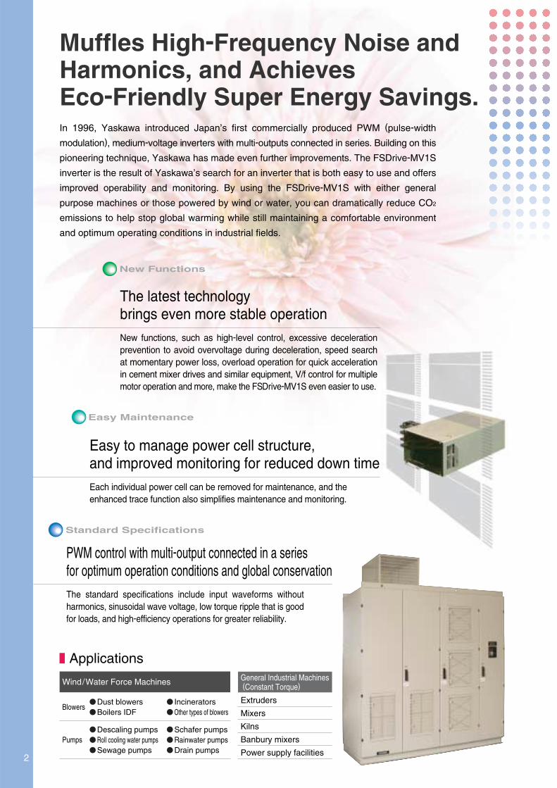
Muffles High-Frequency Noise andHarmonics, and AchievesEco-Friendly Super Energy Savings.In 1996, Yaskawa introduced Japan’s first commercially produced PWM (pulse-width
modulation), medium-voltage inverters with multi-outputs connected in series. Building on this
pioneering technique, Yaskawa has made even further improvements. The FSDrive-MV1S
inverter is the result of Yaskawa’s search for an inverter that is both easy to use and offers
improved operability and monitoring. By using the FSDrive-MV1S with either general
purpose machines or those powered by wind or water, you can dramatically reduce CO2
emissions to help stop global warming while still maintaining a comfortable environment
and optimum operating conditions in industrial fields.
The latest technologybrings even more stable operation New functions, such as high-level control, excessive deceleration prevention to avoid overvoltage during deceleration, speed search at momentary power loss, overload operation for quick acceleration in cement mixer drives and similar equipment, V/f control for multiple motor operation and more, make the FSDrive-MV1S even easier to use.
Each individual power cell can be removed for maintenance, and the enhanced trace function also simplifies maintenance and monitoring.
PWM control with multi-output connected in a seriesfor optimum operation conditions and global conservationThe standard specifications include input waveforms without harmonics, sinusoidal wave voltage, low torque ripple that is good for loads, and high-efficiency operations for greater reliability.
Easy to manage power cell structure,and improved monitoring for reduced down time
IncineratorsOther types of blowers
Dust blowersBoilers IDF
Descaling pumpsRoll cooling water pumpsSewage pumps
Blowers
PumpsSchafer pumpsRainwater pumpsDrain pumps
Extruders
Mixers
Kilns
Banbury mixers
Power supply facilities
Applications
Wind/Water Force Machines General Industrial Machines (Constant Torque)
2

StartingCharacteristics
Motor Current
Motor Torque
Motor Speed
Medium-voltage Three-phase Induction Motor
The Latest Technology Brings Even More Stable Operation.
High-level Control
Stable Deceleration Operation
A function to prevent excessive deceleration has been added to avoid overvoltage during deceleration.When the DC busbar voltage in the cell rises during deceleration in the set time, the inverter stops deceleration. This prevents DC busbar overvoltage from occurring, and enables continuous operation.
Controlled and Secure Operation at Momentary Power Loss
OutputFrequency
Maintains the speed referenceto avoid overvoltage
Deceleration Time (Set Value)
Time
Restarts deceleration after theDC busbar voltage drops to normal.
FSDrive-MV1S New Functions
Full-scale flux vector control improves starting torque characteristics and responsiveness to fluctuations in the load, without using a speed detector. Attain stable operation even when there are load fluctuations.
The inverter continues to operate during a momentary power loss of several cycles1.The inverter re-accelerates to the reference speed almost at the same time as the power is restored to ensure that the drive starts smoothly.
1 : Holding time depends on the load forms or operation status.
Instantaneous Searching Function
Function to Prevent Excessive Deceleration
KEB Function2
2 :250 ms
Speed ReferenceSpeed Reference Speed ReferenceSpeed Reference
Input VoltageInput Voltage
Motor Speed
Motor Current
Motor Speed
Motor Current
Input VoltageInput Voltage
Motor Speed
Motor Current
Motor Speed
Motor Current
KEB (Kinetic Energy Back-up) Function:Function to continue operation without base-blocking during momentary power loss.

Note In multiple motor operation models, each motor requires a protective device.
Parallel operation of mutiple motors with one inverter is possible and the scale reduction of the drive equipment is possible.
:
Easy to manage power cell structure,and improved monitoring for reduced down time.
Operation Using Multiple Motors
Enerhy saving Control
High efficiency drive is realized by minimizing the motor current to the required output torque. In this way,outstanding energy saving effect is shown in the drive of fans and pumps to machines for general use.
Individual Cell Maintenance (140 A or Less)
Each individual cell can be removed for replacement or maintenance. This structure shortens replacement time and simplifies maintenance.
The enhanced trace function and LAN compatibility enable you to easily monitor the operation status for protective maintenance and quick intervention.
MotorInverter Panel
FSDrive-MV1S Easy Maintenance
Easy Monitoring of Operation Status
4

5
FSDrive-MV1S Standard Specifications
The PWM Control with Multi-output Connected in a SeriesHelps Protect Nature, Power, and the Machine.
The Most Efficient Use of Energy
Since this Inverter is a direct medium-voltage inverter that does not need an output transformer, it can maintain a power conversion efficiency of approx. 97% so as not to waste energy.Power supply factor is always kept at approx. 0.97.Since the power factor does not change even if the operation speed changes, no power factor improvement capacitor is needed.
Perfect Harmonics Measure
The input waveform is sinusoidal wave and rarelycontains harmonics.Therefore, the inverter single-unit has cleared theharmonics control guideline specified by the Ministry of Economy, Trade and Industry (former ministry of International Trade and Industry) so that any harmonics filter or active filter is not needed.
Guideline of the Ministry of Economy, Trade and Industry, and measured value of harmonics in input current of FSDrive-MV1S (In case of 3.3 kV, 630 kW, 60 Hz, all-load contract demand 630 kW)
Easy Application to Existing Motors
By employing the multiple PWM control, sinusoidal wave voltage is output to the Inverter without a filter.Therefore; the following features have been achieved:
Free from oscillation surge voltage affecting the motor Low torque ripple good for loads Noise as low as commercial power supply operation
The existing motors or wiring cables can be usedwithout being modified.
Power Conversion Efficiency Ratio100
90
80
70
60
50 60 70 80 90 100
Effi
cien
cy a
nd P
ower
Fac
tor
(%)
Speed (%)
Power Conversion Efficiency(approx. 97%)
Power Supply Power Factor (0.97 or more)
Input Waveform
Current
Voltage
Output Waveform
Current
Voltage
(Unit : %)
Guideline
FSDrive-MV1SMeasured Value
5th
4.00
1.07
7th
2.80
0.53
11th
1.80
0.90
13th
1.50
0.49
17th
1.10
0.78
19th
1.00
0.76
23rd
0.87
0.06
25th
0.80
0.26
29th
0.80
0.11
31st
0.80
0.07
6
回路構成
PowerSupplyInput
Output
RU
S
TV
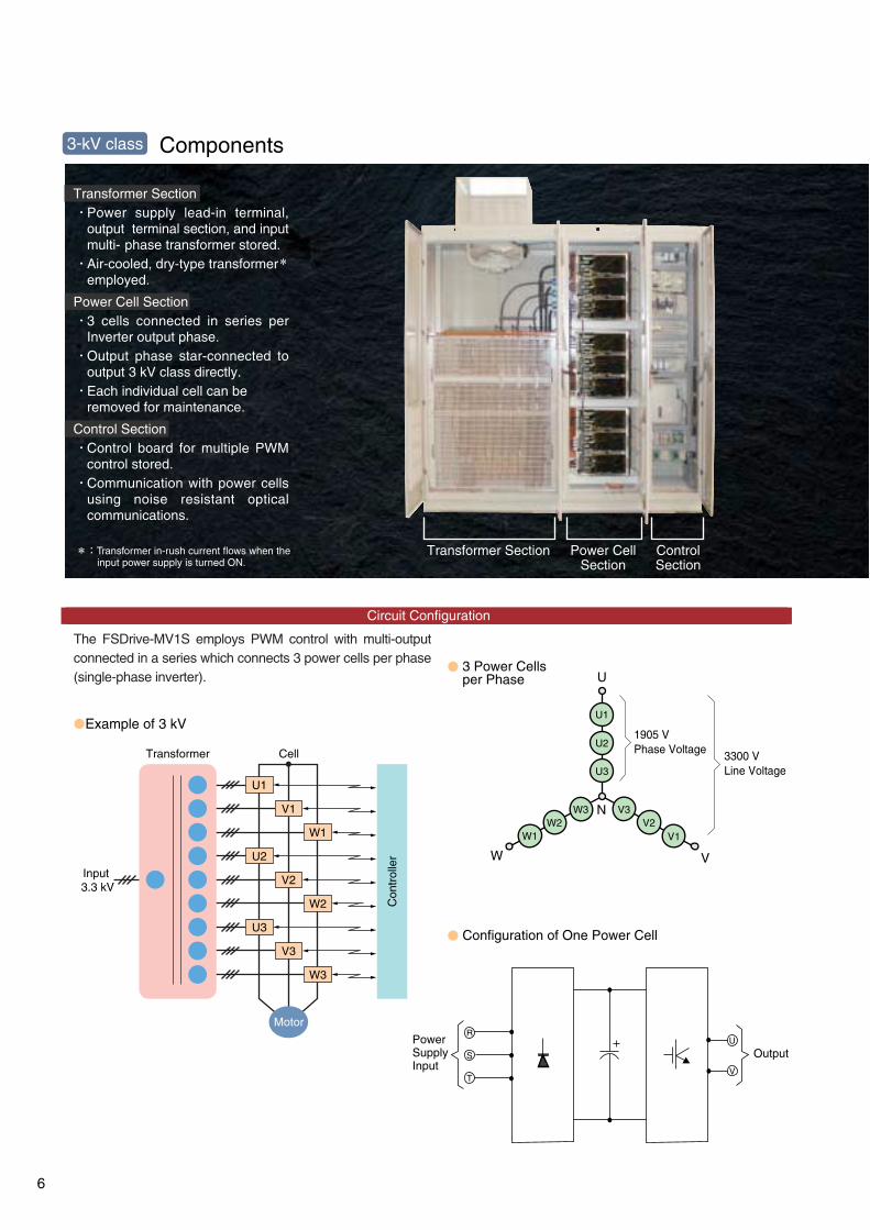
Components
Transformer Section
Power Cell Section
Control Section
Power supply lead-in terminal, output terminal section, and input multi- phase transformer stored.Air-cooled, dry-type transformer*employed.
3 cells connected in series perInverter output phase.Output phase star-connected tooutput 3 kV class directly.Each individual cell can be removed for maintenance.
Control board for multiple PWMcontrol stored.Communication with power cellsusing noise resistant opticalcommunications.
*:Transformer in-rush current flows when the input power supply is turned ON.
Transformer Section Power CellSection
ControlSection
Circuit Configuration
The FSDrive-MV1S employs PWM control with multi-output connected in a series which connects 3 power cells per phase (single-phase inverter).
3 Power Cellsper Phase
Example of 3 kV
Configuration of One Power Cell
U
W
1905 VPhase Voltage
V
N
3300 VLine Voltage
U1
U2
U3
V2V1
W3W2
W1
V3
3-kV class
Input 3.3 kV
Motor
Transformer Cell
U1
U2
U3
V1
W1
V2
W2
V3
W3
Con
trol
ler

Upper part : Control SectionLower part : Transformer Section
Power Cell Section
7
回路構成
Example of 6 kV
The FSDrive-MV1S employs PWM control with multi-output connected in a series which connects 6 power cells per phase (single-phase inverter).
6 Power Cellsper Phase
Configuration of One Power Cell
Components6-kV class
*:Transformer in-rush current flows when the input power supply is turned ON.
Circuit Configuration
Input6 kV
Motor
Transformer Cell
U1V1
W1U2
V2W2
U3V3
W3U4
V4W4
U5V5
W5U6
V6W6
3810 VPhaseVoltage 6600 V
LineVoltage
U
W V
N
U1
U6
U5
U4
U3
U2
W3W2
W1 V1V2
V3V4
V5V6W6
W5W4
Con
trol
ler
PowerSupplyInput
Output
RU
S
TV
Transformer Section
Power Cell Section
Control Section
Power supply lead-in terminal, output terminal section, and input multi- phase transformer stored.Air-cooled, dry-type transformer*employed.
6 cells connected in series perInverter output phase.Output phase star-connected tooutput 3 kV class directly.Each individual cell can be removed for maintenance.
Control board for multiple PWMcontrol stored.Communication with power cellsusing noise resistant opticalcommunications.

RS485/RS232
L1 CN
39
CN
9C
N7
CN
43C
N44
CN
40C
N22
CN
23
ISOAMP
ISOAMP
AI_0
RRC
EA
SCTC
RST
UMV
W
TS
R
TS
GND1
12
23FG
AO_0ISOAMP
GNDFG
AO_1GNDFG
ISOAMP
ISOAMP
AI_1GND
123FG
IP24
DI_0
1
1
1
30
32 31
33
3435
36
4142
4344
39
40
37
DO_0A
CN
28
DO_0COM
DO_1ADO_1COM
DO_2ADO_2COM
DO_3ADO_3COM
DO_4ADO_4COMDO_4B
DO_5ADO_5COMDO_5B
DO_6ADO_6COMDO_6B
DO_7ADO_7COMDO_7B
2
34
56
78
132
4657
1
465
32
123
123
2
3
4
5
6
7
8
9
10111213
234
567891011
12
DI_1
DI_2
DI_3
DI_4
DI_5
DI_6
DI_7DI_8
DI_9IP24
IG24DI_COM1
24VDC
IG24
L2L3
External Fault Reset
5-V Differential Output PGPulse Input (5-V Differential Input)
Phase A/B/Z Input
Pulse Input (Photocoupler Input)Phase A/B/Z Input
PG
PG
12-V Open-collector Output PG
Operation Interlock
Operation Interlock
−10V to +10V
−10V to +10V
Power Supply for Digital Input
PC for Maintenance
Relay Contact Output: 8 points
L
L
L
L
L
CN35
RS-485
RS-232
L4L5L6
L7L8L9
CPU Board
CN34CN1RS-232C
CN36-38
CN
27C
N26
CN
21C
N20
ISOAMP
Connections
Main-circuitPower Supply,AC 3-phase,3/3.3 kV,or 6/6.6 kVat 50/60 Hz
Ground Resistance:Less than 10Ω
Frequency Reference4 to 20 mA DC,or 0 to 10 VDC
ControlPower Supply,3-phase,200/220 V, 380 V,or 400/440 VACat 50/60 Hz
Cooling Fan Power SupplyController Power Supply
Medium-voltagePrimary Panel ON
Spare
Speed Reference Selection
Digital Input:10 Points
Analog Input : 2 Points
Input Voltage Output Current Output Voltage Converter
Digital Operator
Output Frequency4 to 20 mA DC
Output Current4 to 20 mA DC
During Run
Operation Ready
Major Fault
Minor Fault
Load Power SupplyLoad
Medium-voltagePrimary PanelChangeoverCommand
Analog Output : 2 Points
Resistor Board for Detecting Output Current
L
L
L
L
L
L
L
L
L
L
: Either one can be selected.
8

Main Circuit (For all models)
Terminal Functions
R
S
T
U
V
W
EA
RC
SC
TC
Main-circuit input power supply
3/3.3 kV or 6/6.6 kV 50/60 Hz
Main-circuit output power supply
Ground resistance: Less than 10ΩControl power supply
200/220 V, 380 V, 400/440 V 50/60 Hz
Terminal No. Application
Control Circuit (For all models)
L1
L2
L3
L4
L5
L6
L7
L8
L9
1
2
3
4
5
6
7
8
9
10
11
12
30
31
32
33
34
35
36
37
39
40
41
42
43
44
Frequency reference
Output frequency
Output current
Operation interlock
Operation interlock(Optional)
Speed reference selection(Optional)
External fault reset(Optional)
Spare
Inverter major fault
During run
Operation ready
Inverter minor fault
Medium-voltage primary panel changeover command
Spare
Spare
Terminal No.
4 to 20 mA
0 to 10 VDC
4 to 20 mA
4 to 20 mA
“Closed” at medium-voltage primary panel ON
ON when operation interlockis enabled.
ON when operation interlocksis enabled.
ON when speed is specified.OFF with external input command.
ON when external fault is reset
―
“Closed” at major fault.
“Closed”during run.
“Closed”at operation ready.
“Closed” at minor fault.
Host power-control panel openwhen contact is“closed”.
―
―
Function
Input impedance:10MΩ Input impedance:1MΩ
Load resistance : 500Ω or less
Load resistance : 500Ω or less
100/110 VAC circuit
100/110 VAC circuit
100/110 VAC circuit
100/110 VAC circuit
100/110 VAC circuit
100/110 VAC circuit
Dry-contact
Contact capacity: 250 VAC, 1 A
Dry-contact
Contact capacity: 250 VAC, 1 A
Dry-contact
Contact capacity: 250 VAC, 1 A
Dry-contact
Contact capacity: 250 VAC, 1 A
Dry-contact
Contact capacity: 250 VAC, 1 A
―
―
Signal LevelType Signal Name
InputSignal
OutputSignal
InputSignal
OutputSignal
Medium-voltageprimary panel ON
9

Rdy Display
Menu KeyChanges the display of operation and programming mode.
: Increment Key : Decrement Key
Selects mode, group, function, parameter name or set value.
Rotating Direction Display
Lights when selecting input mode from the control circuit terminal.SEQ:LED lights when selecting run command from
control circuit terminal.R E F:LED lights when selecting frequency reference
from control circuit terminals A1, A2, and A3.
Remote Mode
FWD:LED lights at forward run.R E V:LED lights at reverse run.
Alarm Display
Can operate when a run command is input.
Data DisplayDisplays data for monitoring, parameters, and set values.(1 line×13 characters and 3 lines×16 characters)
Escape KeyReturns to the status entered before [DATA/ENTER] key was pressed.
DATA/ENTER KeySelects mode, group, function or parameter name. Displays each parameter set value while displaying a parameter name. By pressing this key again, the set value is written in.
Shift /Reset KeySelects a digit of a set value to be changed. The selected digit blinks.(Resets operation at faults.)
Run Command KeysRun command keys for use by digital operator. Enabled only in the drive mode.
Operation Mode Selection KeyThe operation mode is alternated with REMOTE (control circuit terminal) and LOCAL (digital operator) (When run command and frequency reference are set at control circuit terminal.)
Mode Display
Digital Operator Functions
Digital Operator
*: RUN or STOP LED turns ON , OFF, or blinks in accordance with each operation.
Inverter Output Frequency
Frequency Setting
:ON :Blinking :OFF
RUNLEDSTOPLED
STOPSTOPRUN
JOG
FWD/REV
RUN*
STOP*
Jog run is enabled while depressing this key.Selects forward or reverse run.Forward and reverse run is alternated.Red LED lights by depressing RUN.Red LED lights by depressing STOP.
: : : :
DRIVE
QUICK
ADV
A. TUNE
LED lights at Drive Mode.
LED lights at Quick Programming Mode.
LED lights at Advanced Programming Mode.
LED lights at Autotuning Mode.
: : : :
10

Monitor Display Procedure
Key Operation Operator Display①Power ON ・Displays frequency reference value. ②Operation Condition Setting ・Select LOCAL mode. ③Frequency Setting ・Change reference value. ・Write-in set value.
(cont'd)
・Select output frequency monitor display. ④Forward Run ・Forward Run(15Hz) ⑤Reverse Run ・Switch to reverse run. ⑥Stop ・Decelerates to a stop.
-DRIVE- Rdy
【Display at Startup】
【Mode Selection Display】 【Frequency Setting Display】 【Monitor Display】
U1- 01=100.00%U1-02=60.00HzU1-03=10.1A
-DRIVE- RdyMonitor
U1 -01=100.00%U1-02=60.00HzU1-03=10.1A
-QUICK-
Control Method
A1-02=2 *2*IM VEC. PG-Less
“2”
-ADV-
InitializationA1 -01=2
-ADV-
Access LevelA1- 01 =2 (0~9999)“2”
-A TUNE-
Tuning Mode SelT1- 01 =0 *0* (0~2) “0”
Fault History
001 A BATWeak Battery
03/07 01:28:45
-A TUNE-
Tuning Mode SelT1- 01 = 0 *0* (0~2) “0”
-ADV-
Access LevelA1- 01 = 0 002
(0~9999)“2”
-QUICK-
Control Method
-DRIVE- RdyFrequency Ref
U1- 01 =100.00%U1-02=60.00HzU1-03=10.1A
-DRIVE- RdyFrequency Ref
U1- 01=100.00%(0.00~100.00)“0.00%”
-DRIVE-
INV* MODE sel *
Operation
-QUICK-
INV* MODE sel *
Quick Setting
-ADV-
INV* MODE sel *
Programming
-A TUNE-
INV* MODE sel *
Tuning Mode
INV* MODE sel *
Fault History
A1-02=2 *2*IM VEC. PG-Less
“2”
Note: expresses blinking of numbers.
FWDREV
DATAENTER
DATAENTER
RESET
LOCALREMOTE
MENU
ESC
ESC
ESC
ESC
ESC
ESC
MENU
MENU
MENU
MENU
DATAENTER
ESC
DATAENTER
DATAENTER
DATAENTER
ESC
DATAENTER
ESC
ESC
RESET
RESET
ESC
DATAENTER
ESC
DATAENTER
DATAENTER
DATAENTER
DATAENTER
DATAENTER
REMOTE(SEQ.REF)LED OFF FWD LED ON
REMOTE(SEQ.REF)LED ON (d1-01=0.00 %)
STOP LED ON(RUN LED blinks during deceleration.)
REV LED ON
-DRIVE- RdyFrequency Ref
U1- 01 = 0.00%U1-02= 0.00HzU1-03= 0.0A
-DRIVE- Rdy
U1- 01 = 25.00%U1-02= 0.00HzU1-03= 0.0A
-DRIVE- Rdy
U1- 02 = 0.00HzU1-03= 0.0AU1-04= 2
-DRIVE- Rdy
U1- 02 = 0.00HzU1-03= 0.0AU1-04= 2
-DRIVE- Rdy
U1- 02 =15.00HzU1-03= 1.5AU1-04= 2
-DRIVE- Rdy
U1- 02 =15.00HzU1-03= 1.1AU1-04= 2
-DRIVE- Rdy
(0.00 100.00)0.00%
-DRIVE- Rdy
U1-01=025.00%(0.00 100.00)
0.00%
-DRIVE- Rdy
U1-01=025.00%(0.00 100.00)
0.00%
-DRIVE- Rdy
RUN LED ON
U1-01=000 .00%
Easy Operation with Digital Operator
Description Key Operation Operator DisplayDescription
Frequency Ref
Frequency Ref
Enter Accepted
Frequency Ref
Frequency Ref
Output Freq
Output Freq
Output Freq
Output Freq
Frequency Ref
Access Level
11

Software Functions
The FSDrive-MV1S flexible inverter incorporates a variety of application features. Select special functions from a multitude of possibilities to perfectly match your machine requirements.
FSDrive-MV1S
IM
Option CardCommunication
Digital Operator
RST
UVW
Analog Output
Analog InputDigital Output
Output OptionInput Option
Digital Input
Pulse Input
PowerSupply
Function
Energy Saving Control
3-wire Sequence
Operating Site Selection
Speed Search Operation
DC Injection Braking at Start
Commercial PowerSource/InverterSwitchover Operation
Accel/Decel TimeChangeover Operation
Frequency Hold OperationUP/DOWN Command
Multi-step SpeedOperation
Application Description of Function
Easy operation
Easy operationEasy operation
Temporarily holds frequencies during acceleration or deceleration.Sets speed by ON/OFF from a distance.
Starting the free running motorStarts the inverter at the specified frequency, automatically detects thesynchronization point, and performs at the operation frequency.No speed detector is required.When the direction of the free running motor is not fixed, the speed searchoperation function is difficult to use. The motor can be automaticallystopped by DC injection braking, and be restarted by the inver ter.
Switching of commercial power source to inverter or vice versa is donewithout stopping the motor.
Starting the free running motor
Simple configuration of control circuit
Most efficient automatic operation Supplies voltage to motor to always be most effective according to load androtating speed.
Operation and settings can be selected while the inverter is online.(digital operator/external instruction, signal input/output)
Automatic switching betweencommercial power source and inverter
Schedule operation underfixed speed and positioning
The accel/decel time changeoverwith an external signal
Multi-step operation (up to 8-step) can be set by setting the contact combinations.
The accel/decel times are switched by an external contact signal.
Operation can be accomplishedusing a spring-loaded push-button switch.
Run Signal
Zero-speed Signal
Frequency (Speed) Agreed Signal
Low Voltage Signal
Overtorque Signal
Multi-function Analog Input Signal
Prohibit Setting ofSpecific Frequency(Frequency Jump Control)
Upper/Lower Frequency Limit Operation
Free UnintentionalSpeed Agreement SignalOutput FrequencyDetection 1
Output Frequency Detection 2
Base Block Signal
Frequency ReferenceSudden Change Detection
Multi-function Analog Output Signal
“Closed” at or over an arbitrary output frequency.
“Closed” at or below the arbitrary output frequency.
Always “closed” when the inverter output is OFF.
Easy operation
Prevent mechanicalvibration in the equipment
The motor simply passes through the preset speed, but continuous runningcannot be done at this speed. This function is used to avoid the mechanicalresonance point of the equipment.
Protection of machine,improvement of operation reliability
“Closed” when overtorque setting operation is accomplished.
Functions as supplementary frequency reference. Also used for fine control of input reference, output voltage adjustment, external control of accel/decel time, and fine adjustment of overtorque detection level.
Torque LimitThe inverter can be switched to coasting or motor speed reducing modeas soon as it reaches a certain preset torque level. For pump or blower,the operation frequency can be automatically reduced to the load balancingpoint, according to the overload condition, and prevent overload tripping.
Protection of machine, improvement of operation reliability, torque limit
Motor speed limit The upper and lower limits of the motor speed, reference signal bias and gain can be set independently without peripheral operation units.
Zero-speed interlock “Closed” during operation. “Open” during coasting to a stop.Can be used as interlock contact point during stop.
Zero-speed interlock “Closed” when output frequency is under min. frequency.
Reference speed reach interlock The contact closes when inverter output frequency reaches the set value.Can be used as an interlock for lathes, etc.
System protection for undervoltage “Closed” only when tripped by low voltage. Can be used as a countermeasure power loss detection relay.
Reference speed agreed interlock “Closed” when the speed agrees at arbitrary frequency reference.
Gear change interlock, etc.
Gear change interlock, etc.
Operation interlock, etc.
Improvement of operation reliability “Closed” when the frequency reference suddenly drops to 10 % or below of the set value.Can be used to detect an error in the host controller.
V/f control (for multiple motor operation)
Excessive decelerationprevention
Multiple motor control Simultaneous parallel operation of multiple motors is possible.Single or multiple motor control is selected with the user parameter.
Monitor function enhancement Use two of the following devices: a frequency meter, ammeter, voltmeter, wattmeter, or U1 monitor.
S1 RUN
RUNSTOP
STOPFWD/REV
S2S5SC
Improvement of operation reliability When the DC busbar voltage in the cell rises during deceleration, the inverter stopsdeceleration and maintains the speed. (Disable/enable selection by parameter.)
12

Protective Functions
Main Circuit Overvoltage
Main Circuit Undervoltage
Control Power Fault
Inverter Overcurrent
Output Overvoltage
Motor Overload
Inverter Overload
Overtorque 1
Overtorque 2
Undertorque 1
Undertorque 2
PG Disconnected
Excessive Speed Deviation
Overspeed
Output Ground Fault
Output Open-phase
Control Fault
Digital Operator Disconnected
Digital Operator Communications
Error 1
Digital Operator Communications
Error 2
EEPROM Error
A/D Converter Error
Hardware Fault
Modulator Watchdog Timeout Fault
CPU Fault
Analog Power Supply Fault
Lowered Battery Voltage
External Fault
(Input Terminals S3 to S16)
The voltage of the power supply for the main circuit exceeded 120% of the rated voltage.
The voltage of the power supply for the main circuit dropped to 55 % of the rated voltage or less.
The voltage of the control power dropped.
The current from the inverter exceeded the overcurrent detection level (approx. 132 % of the rated current).
The output voltage exceeded the voltage set in L9-06 for the time set in L9-07.
The motor overload protection function has operated based on the internal electronic thermal value.
The inverter overload protection function has operated based on the detected current.
There has been a current greater than the setting in L6-02 for longer than the time set in L6-03.
There has been a current greater than the setting in L6-05 for longer than the time set in L6-06.
There has been a current less than the setting in L6-02 for longer than the time set in L6-03.
There has been a current less than the setting in L6-05 for longer than the time set in L6-06.
PG pulses were not input when the inverter was outputting a frequency.
The speed deviation has been greater than the setting in H7-10 for longer than the time set in H7-11.
The speed has been higher than the setting in H7-08 for longer than the time set in H7-09.
・The ground fault current at the inverter output exceeded approx. 25% of the rated output current.
・The total value of the output voltage for three phases exceeded the
value set in L9-21 for the time set in L9-22.
An open-phase occurred at the inverter output.(Detected when L8-07 is set to Enabled.)
The torque limit was reached continuously for 3 seconds or longer during
a deceleration stop at open-loop vector control.
The connection to the digital operator was broken during operation for a run command from the digital operator.
Communications with the digital operator were not established within 1 second after the
power was turned on.
After communications were established, there was a communications error with the
digital operator for more than 2 seconds.
The inverter control circuit was damaged.
The power-supply voltage (±15V) of the analog detection circuit was lowered.
The battery voltage (3V) was lowered.
An “ external fault ” was input from a multi-function input terminal.
IOV
IUV
CUV
IOC
OOV
OL1
OL2
OL3
OL4
UL3
UL4
PGO
DEV
OS
OGF
LF
CF
OPR
CPF00
CPF01
CPF03
CPF05
HDE
DTM
CER
CTF
BAT
EF3 to
EF16
Over Voltage
Under Voltage
CTL PS Under Volt
Over Current
Output Ov Fault
Motor Over loaded
INV Overloaded
Overtorque Det 1
Overtorque Det 2
Under torque Det 1
Under torque Det 2
PG Open
Speed Deviation
Overspeed Det
Ground Fault
Output Pha Loss
Out of Control
Opr Disconnect
COM-ERR
(OP&INV)
COM-ERR
(OP&INV)
EEPROM Error
External A/D Err
HARD Fault
MB Watchdog Flt
CTL CPU Fault
Analog Pwr Fault
Battery Lowered
Ext Fault
(S3 to S16)
Cell Overheated
CCB Control Power Fault
Communications Error (Link Error)
Burnout of Power Fuse
Cell Fault
The cell temperature was greater than 90 C.
The voltage of the cell's control power supply dropped.
A cell communications error (link error) occurred.
The input fuse of the battery cell burned out.
One of the following faults occurred in the cell.
・DC busbar overvoltage: The voltage of the power supply of the cell's main circuit
increased to a value greater than the allowable voltage.
・DC busbar undervoltage: The voltage of the power supply of the cell's
main circuit dropped to a value less than the allowable voltage.
・DC capacitor overvoltage: The capacitor voltage of the cell's main circuit
increased to a value greater than the allowable voltage.
・Communications error (parity check error): A cell communications error (parity check error) occurred.
・IGBT Q1 to Q4 fault: Short circuit between the emitter and the collector of IGBT Q1 to Q4.
TMP
UVB
LIN
FUB
CFA
xx:Over Temp
xx:PWR FLT
xx:LINK FLT
xx:FUB FLT
xx:OVR VOLT
xx:UDR VOLT
xx:CAP FLT
xx:COM FLT
xx:Q1~4 FLT
Fault Display Meaning
If a fault occurs, the type of fault is displayed on the digital operator, and details are stored inthe internal memory.
Drive Faults
Cell Faults
:×× represents the cell number.
Fault Display Meaning
13

Specifications
Control MethodMain CircuitFrequency Control RangeFrequency Control AccuracyAnalog Input ResolutionAccel/Decel TimeMain Control Functions
Digital OperatorDisplay Tools on PC Main Circuit
Maximum Applicable Motor Capacity1
Maximum Applicable Motor Capacity1
Model: CIMR-MV1S A
Model: CIMR-MV1S C
Nominal Capacity kVA
kW
A
kVA
kW
A
Nominal Capacity
Main-circuit Power Supply
OutputRating
3kV
Class
6kV
Class
Communication Option Cards
CP-215
communications I/F card
215IF
Card Name
CP-218
communications I/F card
218IF
Code No. Function
Used for running or stopping the inverter, setting or referencing parameters, and monitoring output frequency, output current, or similar items through CP-215 communications with the host controller.Used as real-time network at high speeds with N/N as control method for media access. Cyclic and message communications with a shared memory are available.
Used for running or stopping the inverter, setting or referencing parameters, and monitoring output frequency, output current, or similar items through CP-218 communications with the host controller.Used as Ethernet with MEMOBUS, MELSEC, or no protocol.
Rated Output CurrentRated Output Voltage
Main-circuit Power SupplyInverter Efficiency / Power FactorOver Load ToleranceCooling MethodControl Power Supply
Protective Functions
Maintainability
Applicable Standards
Enclosure
CabinetSpecifications
Input Transformer
No. of I/O TerminalsTemperature Protection
Communication (optional)
Efficiency : Approx. 97%, Power Factor: 0.97 or more110% / 60seconds, 120% / 15secondsForced air-cooling by fan (with failure detection)
Controller : 3-phase, 200/220, 380, 400/440 V±10%, 50/60 Hz ±5%, 3kVA or more2
Open-loop vector control, flux vector control, V/f control (for multiple motor operation)Voltage type PWM control with multi-output connected in a series
0.01 to 120 Hz
±0.5%
0.03 Hz
0.1 to 6000 sRestart after momentary power loss3, torque limit, acceleration stall prevention, catching the coast, Excessive deceleration prevention,operation prohibition at specified speeds, S-curve accel/decel, multi-step speed operation, KEB function, Energy saving control etc.Overcurrent, overvoltage, undervoltage, output ground fault, output open-phase, cooling-fan error,overload, motor overheat, etc.Applicable to various types such as Modbus, CP-215, and CP-218 (Ethernet)
Status display, fault display, run command, parameter setting, parameter referenceTrend display, data analysis toolModule configurationClass H dry type, N/+5% /+10% tap, secondary multi-phase windingDigital input: 10 points: digital output: 8 points: analog input: 2 points : analog output : 2 points
Power cells: protected by thermistor for temperature, transformer : protected by thermostat
Rated Output CurrentRated Output Voltage
3-phase, 3 /3.3 kV (sinusoidal wave)3-phase, 3 / 3.3 kV±10%, 50 / 60 Hz±5%
3-phase, 6 / 6.6 kV(sinusoidal wave)
3-phase, 6 / 6.6 kV±10%, 50 / 60 Hz±5%
Conditions Specifications
AtmosphereAmbient TemperatureRelative HumidityStorage TemperatureAmplitude
JIS, JEC, JEMGeneral environmental conditions (free from dust and corrosive gases)−5 to +40 C45 to 85%RH (no condensing)
0 to +50 C1000 m or lessMade of enclosed steel sheets, vertically-standalone type, protective front panal type5Y7/1 semi-gloss both for inner and outer facesIP40 (dustproof type)
Form
Painting
Standard Specifications
1
2
3
:
:
:
The figures shown for maximum applicable motor output were obtained by using Yaskawa's standard four-pole motors.The required control power supply capacity will vary, depending on the inverter capacity.When the restart function for the momentary power loss is used, an uninterruptive power supply unit for the control power supply is needed optionally.
Notes:12
This inverter does not have any regenerative braking function.Please inquire of YASKAWA next items
11000V input and output voltage for power circuit4160V input and output voltage for power circuitLife extension of the panel cooling fanApplication to non-standard environmental conditions
OutputRating
Control
Specifications
Env
ironm
ent
Environmental Conditions
7910161-6030X-S010Y
7910161-6040X-S010Y
JEBC-61603
JEBC-61604
132200
132
35
200285
200
50
315400
315
70
450570
450
100
630800
630
140
9001150
900
200
13C1500
1250
260
15C1900
1500
330
18C2300
1800
400
25C3000
2500
520
250400
250
35
400570
400
50
630800
630
70
9001150
900
100
13C1600
1250
140
18C2300
1800
200
25C3000
2500
260
36C4600
3600
400
30C3800
3000
330
43C5300
4300
460
50C6000
5000
520
14
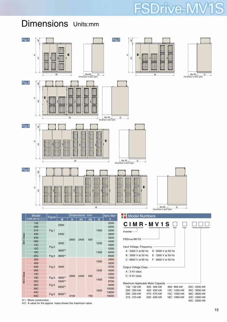
Dimensions Units:mm
Input Voltage, Frequency
Output Voltage Class
12
::Block construction.A value for the approx. mass shows the maximum value.
ModelCIMR-MV1S
Figure Approx. Mass2
kgDimensions mm
W H DH1 H2
3kV
Cla
ss6k
V C
lass
C I M R - M V 1 SInverter
FSDrive-MV1S
Maximum Applicable Motor Capacity
Model Numbers
W
W D
W D
W D
W DDMax.685Dimension a door open
Max.785Dimension a door open
Max.785Dimension a door open
Max.785Dimension a door open
Max.685Dimension a door open
H
H2
H1
H
H2
H1
H
H2
H1
H
H2
H1
H
H2
H1
Fig.1 Fig.2
Fig.3
Fig.4
Fig.5
A
B
C
:
:
:
3300 V at 60 Hz
3000 V at 50 Hz
6600 V at 60 Hz
132200250315
::::
132 kW200 kW250 kW315 kW
400450570630
::::
400 kW450 kW570 kW630 kW
90013C15C18C
::::
900 kW1250 kW1500 kW1800 kW
25C30C36C43C50C
:::::
2500 kW3000 kW3600 kW4300 kW5000 kW
A
C
:
:
3 kV class
6 kV class
D
E
F
:
:
:
6000 V at 50 Hz
3300 V at 50 Hz
6600 V at 50 Hz
13220031545063090013C15C18C25C25040063090013C18C25C30C36C43C50C
Fig.1
Fig.2
Fig.4
Fig.2
Fig.3
Fig.4
Fig.5
200022002500280035004400490053006400950029003200370045005300700087009400
120001360016000
2300
2400
3200
3600
5600
3400
46005500
6500
8000
1
1
1
1
1
1
2900
2900
3150
2400
2400
500
500
750
1000
1200
1400
1000
1200
1400
1600
15

Energy-saving Power Calculation for Fan/Blower
Consumed power of blower motor
(%)
Air Flow, Speed(%)
Mot
or I
nput
110
100
90
80
70
60
50
40
30
20
10
00 30 40 50 60 70 80 90 100
Note: Shaft power at rated airflow amount is to be 100%.
100% SpeedOutlet Damper
100% SpeedInlet Damper
Fluid CouplingSecondary Resistor
Eddy-current Coupling
TheoreticalCurve
SherbiusVVVF
Pole Change
a
bc
Conditions
(1)Applicable motors: 3300 V, 500 kW, 6P.
(with 95% motor efficiency)
(2)70% airflow operation.
(with 90% motor efficiency at 100% airflow)
Power at inlet damper control
Power at inverter energy-saving control
Power saved
500×0.9×0.68*× ≒322kWMotor efficiency
500×0.9×(0.7)=154.3kW3
*Point “a” in the characteristics curve
Motor output (point c)
(322-167)kW×6000h=930,000kWh
Annual power saving by employing inverters
154.3× =162.4kW0.95
1Motor efficiency
Motor input power
162.4× ≒167kW0.97
1Inverter efficiency
Inverter input power (point b)
Assume that the annual operating time is 6,000 hours
(Equivalent to 8.2 months when operating continuously for 24 hours)
155 kWsaved a yearInverter
Energy-savingControl
Damper Control
322 kW
167 kW
The most significant point of the energy-saving operation for fans or blowers is application of speed control by using inverters.Compared to the airflow control by using dampers, theinverter drives can save a great deal of power.
1
2
3
0.951
1
2
FSDrive-MV1S
16

Inverter Capacity Selection
Selection of optimum capacity for blower motors(for actual loads)
F i l l o u t t h e f o l l o w i n g f o r m f o r e s t i m a t i o n.
The applicable inverter capacity is determined as follows whenthe available commercial power supply operation method ischanged into the speed control method.(Example) Motor rating: 500 kW, 4P, 3 kV at 50 Hz
Assuming that:・Motor rated current value : 120 A・Maximum value of actual operation load current : 95 AFor the applicable inverter capacity, rated outputcurrent 100A (nominal capacity 600 kVA) should beselected. (100 A > 95 A)
(Example) Motor rating: 400 kW, 6P, 3.3 kV at 60 HzAssuming that:・Motor rated current value: 88 A・Required overload capacity: 120% for 60 secondsThe applicable inverter capacity will be as shownbelow considering the allowance of 10%;88 A × 1.3 = 115 ATherefore, rated current 140 A (nominal capacity800 kVA) should be selected.(140 A > 115 A)
(Example) Motor rating: 500 kW, 6P, 6.6 kV at 60 Hz Assuming that:・Motor rated current value: 53 A・Required overload capacity: 250% for 60 secondsThe applicable inverter capacity will be as shownbelow considering the allowance of 10%;53 A × 2.6 = 138 ATherefore, rated current 140 A (nominal capacity1600 kVA) should be selected.(140 A > 138 A)
Ambient conditionsIndoors Ambient temperature to Air-conditioning facility (Provided/Not provided)
Humidity % or less
Examination of capacity 1
Examination of capacity 2
Examination of capacity 3
Inverter application for extruder motors
Inverter application for cement kiln motors
Power supply specifications
Commercial power supplyby-pass operation circuit
Power supply shortcircuit capacity MVA Main circuit voltage V Hz Control circuit voltage200/220V,50/60Hz,3-phase 3-step method 400/440V
11
Overload capacity10
Speed control range7
Motor model to be driven5
Operation conditions4
Load machine characteristics3
Name of load machine2
Name of facility or application1
Pattern operation(with/without)9
13
Speedsetting procedure
8
Motor specifications6
12
Not neededNeeded〈Inverter _ commercial power supply operation Automatic changing method Manual changing method〉
%/ Second(s)
Acceleration time Second(s)/ min-1 Deceleration time Second(s)/ min-1
Process signal 4 to 20 mA operation Manual rotating speed adjusting operation
UP/DOWN signal adjusting operation Multi-step speed signal changeover operation
Minimum to Maximummin-1 min-1 Minimum to MaximumHz Hzor
Output kW
Number of poles p Speed min-1
Rated current A Efficiency % Power factor
Voltage V Frequency Hz
Squirrel-cage induction motor Wound-rotor type motor Existing New
Motor current A Operation time Annual hours
Variable torque Proportional torque
Constant torque Constant outputJ(GD2/4) kg・m2
Pump Fan Blower Compressor Extruder Others
FSDrive-MV1S
17

In the event that the end user of this product is to be the military and said product is to be employed in any weapons systems or the manufacture thereof, the export will fall under the relevant regulations as stipulated in the Foreign Exchange and Foreign Trade Regulations. Therefore, be sure to follow all procedures and submit all relevant documentation according to any and all rules, regulations and laws that may apply.
Specifications are subject to change without notice for ongoing product modifications and improvements.
© 2005-2009 YASKAWA ELECTRIC CORPORATION. All rights reserved.
FSDrive-MV1S
YASKAWA
TOKYO OFFICENew Pier Takeshiba South Tower, 1-16-1, Kaigan, Minatoku, Tokyo 105-6891 JapanPhone 81-3-5402-4502 Fax 81-3-5402-4580
YASKAWA MOTOMAN CANADA LTD.298 Labrosse Pointe Claire, QC H9R 5L8, CanadaPhone 1-514-693-6770 Fax 1-514-693-9212
YASKAWA ELETRICO DO BRASIL LTDA.Avenida Fagundes Filho, 620 Sao Paulo-SP CEP 04304-000, BrazilPhone 55-11-3585-1100 Fax 55-11-5581-8795
YASKAWA ELECTRIC KOREA CORPORATION7F, Doore Bldg. 24, Yeoido-dong, Youngdungpo-Ku, Seoul 150-877, KoreaPhone 82-2-784-7844 Fax 82-2-784-8495
YASKAWA ELECTRIC (SINGAPORE) PTE. LTD.151 Lorong Chuan, #04-02A, New Tech Park 556741, SingaporePhone 65-6282-3003 Fax 65-6289-3003
YASKAWA ELECTRIC (SHANGHAI) CO., LTD.No.18 Xizang Zhong Road. Room 1702-1707, Harbour Ring Plaza Shanghai 200001, ChinaPhone 86-21-5385-2200 Fax 86-21-5385-3299
YATEC ENGINEERING CORPORATION5F., No.49 Wu Kong 6 Rd, Wu-Ku Industrial Park, Taipei, TaiwanPhone 886-2-2298-3676 Fax 886-2-2298-3677
YASKAWA ELECTRIC CORPORATION
Printed on 100% recycled paperwith soybean oil ink.
LITERATURE NO. KAEP C710687 00E
09-8-1Published in Japan November 2009 05-12 9 -0


![Evolved energy-saving premium inverter. · motors. The F700P could be the solution to your energy saving needs. Energy saving IM & IPM [Example of blower operation characteristic]](https://static.fdocuments.net/doc/165x107/5f9e3266a17a2f05670c3e4d/evolved-energy-saving-premium-motors-the-f700p-could-be-the-solution-to-your.jpg)