Sunsight AAT RF panel Antenna alignment System 7011 Issue 4 RF Panel Antenna...CD 7011, ISSUE 4,...
28
SUNSIGHT AAT RF PANEL ANTENNA ALIGNMENT SYSTEM AAT Models AAT-30 and AAT-15
Transcript of Sunsight AAT RF panel Antenna alignment System 7011 Issue 4 RF Panel Antenna...CD 7011, ISSUE 4,...

SUNSIGHT AAT RF PANEL
ANTENNA ALIGNMENT SYSTEM
AAT Models AAT-30 and AAT-15

CD 7011, ISSUE 4, 06/23/2017 P a g e | 2 SUNSIGHT AAT RF Panel Antenna Alignment System – AAT MODELS AAT-30 & AAT-15
Document Change History
Issue Date Description
1 02/05/2016 Original Issue
2 02/15/2016 Report generation added
3 04/26/2016 Basic Description and Operation added
Photographs reformatted
Quick Start Guide merged into this
document
Safety warnings added
Table of Contents added
4 06/23/2017 iOS device connection added
Menu table added
Photo reporting added
Tilt/roll calibration instructions added
Troubleshooting added

CD 7011, ISSUE 4, 06/23/2017 P a g e | 3 SUNSIGHT AAT RF Panel Antenna Alignment System – AAT MODELS AAT-30 & AAT-15
Contents Document Change History .................................................................................................................. 2
Safety ................................................................................................................................................. 4
Introduction ........................................................................................................................................ 5
AAT-xx front view ............................................................................................................................ 6
AAT-xx back view ............................................................................................................................. 6
AAT-xx charge ports ......................................................................................................................... 7
AAT-xx LASER rangefinder connection and charge ports................................................................... 7
Basic Description and Operation ......................................................................................................... 8
Order of Operations .......................................................................................................................... 10
Connecting the Handheld Controller to the AAT ............................................................................... 11
Android and Sunsight IP67 Smartphone ......................................................................................... 11
iOS devices (iPhone and iPad) ........................................................................................................ 11
Sunsight Ruggedized tablet (P/N 4200) .......................................................................................... 11
Using the AAT Menu ........................................................................................................................... 12
Profiles/Capture/Report ................................................................................................................ 12
Measure Only/Quick Capture ......................................................................................................... 12
Settings .......................................................................................................................................... 12
Diagnostics..................................................................................................................................... 12
File Management ........................................................................................................................... 12
Tilt/Roll Calibration ........................................................................................................................ 12
Help ............................................................................................................................................... 13
Aligning Standard RF Panel Antennas ............................................................................................... 13
Capturing Alignment Data................................................................................................................. 15
Creating a New Profile ................................................................................................................... 15
Capturing data to a previously created profile................................................................................ 16
Add photos to the capture record .................................................................................................. 17
Using the “Quick Capture” feature ................................................................................................. 18
Add photos to the capture record .................................................................................................. 18
Generating Reports from the AAT..................................................................................................... 21
Notes regarding AAT report generation and retrieval ....................................................................... 23
Using LASER rangefinder (LRF) to capture Above Ground Level (AGL) height ................................... 24

CD 7011, ISSUE 4, 06/23/2017 P a g e | 4 SUNSIGHT AAT RF Panel Antenna Alignment System – AAT MODELS AAT-30 & AAT-15
Checking tilt and roll calibration ....................................................................................................... 26
Troubleshooting ................................................................................................................................ 26
Use and care of the Sunsight AAT ..................................................................................................... 27
Glossary ............................................................................................................................................ 28
Safety The AAT should be handled with the following considerations:
There are no user-serviceable parts within the AAT. All internal repairs must be
performed by Sunsight Instruments.
Use only the Sunsight supplied smart charger to recharge the LiFePO4 battery pack. Use
of a non-approved battery charger will void the battery warranty and can damage the battery
pack.
Never attempt to recharge the batteries outdoors in inclement conditions.
Never short the battery terminals, attempt to disassemble the battery pack, or dispose of
the pack in a fire. Any exhausted battery packs must be disposed of properly. CONTACT
SUNSIGHT INSTRUMENTS IF YOU ARE UNSURE OF HOW TO PROPERLY DISPOSE OF THE
BATTERY.
The AAT is water resistant, but not waterproof. Do not submerge or leave the unit in
standing water. All sealing caps and doors must be secured while in use, particularly during
inclement weather.
Avoid impacting, dropping or rough handling of the AAT. The AAT contains sensitive
electronic components. Rough handling may result in internal component damage.
Care should be taken to avoid impact to the black GPS antennas on the top of the AAT.
If you suspect the AAT is operating incorrectly, contact Sunsight Instruments or an authorized
Sunsight Instruments distributor for support.
www.sunsight.com [email protected] +1 321-244-9443 x2
CD 7011, ISSUE 4, 06/23/2017 P a g e | 5 SUNSIGHT AAT RF Panel Antenna Alignment System – AAT MODELS AAT-30 & AAT-15
Introduction
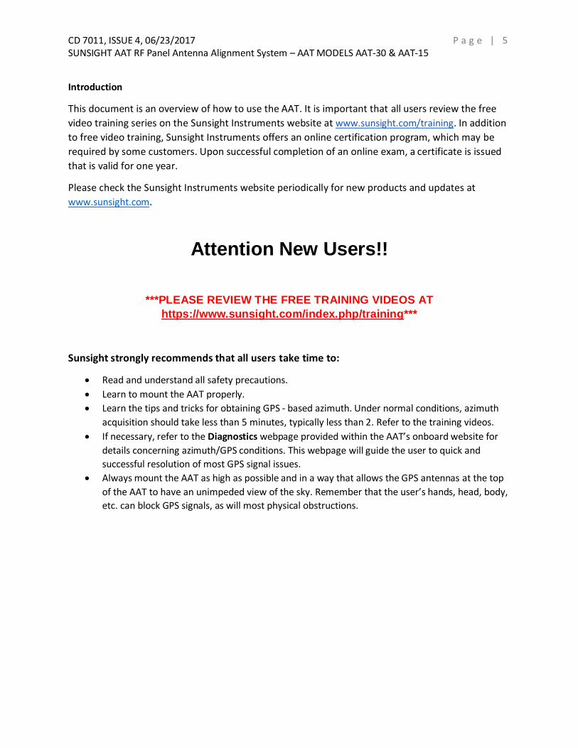
This document is an overview of how to use the AAT. It is important that all users review the free
video training series on the Sunsight Instruments website at www.sunsight.com/training. In addition
to free video training, Sunsight Instruments offers an online certification program, which may be
required by some customers. Upon successful completion of an online exam, a certificate is issued
that is valid for one year.
Please check the Sunsight Instruments website periodically for new products and updates at
www.sunsight.com.
Attention New Users!!
***PLEASE REVIEW THE FREE TRAINING VIDEOS AT
https://www.sunsight.com/index.php/training***
Sunsight strongly recommends that all users take time to:
Read and understand all safety precautions.
Learn to mount the AAT properly.
Learn the tips and tricks for obtaining GPS - based azimuth. Under normal conditions, azimuth
acquisition should take less than 5 minutes, typically less than 2. Refer to the training videos.
If necessary, refer to the Diagnostics webpage provided within the AAT’s onboard website for
details concerning azimuth/GPS conditions. This webpage will guide the user to quick and
successful resolution of most GPS signal issues.
Always mount the AAT as high as possible and in a way that allows the GPS antennas at the top
of the AAT to have an unimpeded view of the sky. Remember that the user’s hands, head, body,
etc. can block GPS signals, as will most physical obstructions.

CD 7011, ISSUE 4, 06/23/2017 P a g e | 6 SUNSIGHT AAT RF Panel Antenna Alignment System – AAT MODELS AAT-30 & AAT-15
AAT-xx front view
AAT-xx back view

CD 7011, ISSUE 4, 06/23/2017 P a g e | 7 SUNSIGHT AAT RF Panel Antenna Alignment System – AAT MODELS AAT-30 & AAT-15
AAT-xx charge ports
AAT-xx LASER rangefinder connection and charge ports

CD 7011, ISSUE 4, 06/23/2017 P a g e | 8 SUNSIGHT AAT RF Panel Antenna Alignment System – AAT MODELS AAT-30 & AAT-15
Basic Description and Operation
The AAT is a self-contained measurement device that can be used to measure azimuth, tilt, roll, latitude, longitude, and height of the device it is attached to. The primary use of the AAT is to provide the necessary measurements to allow a user to align devices such as cellular RF panel antennas.
The AAT can capture measurement results and generate PDF reports and CSV files of the
measurements.
The AAT is controlled by a Wi-Fi connected device (referred to as “Handheld Controller” in this document). This device can be a smart phone, tablet or laptop. Sunsight Instruments offers ruggedized IP67 Android smartphones and tablets for this purpose, or the customer may choose to supply their own. If using a customer-supplied device, a one-time setup is required. See Page 11 or review the training videos at https://www.sunsight.com/index.php/training.
There is NO special software or download required on the Handheld Controller (smartphone,
tablet, or laptop) to operate the AAT. A standard Wi-Fi (802.11 b/g/n) connection and a web
browser are the only requirements to control the AAT.
When powered on, the AAT appears as a Wi-Fi wireless hotspot with the wireless network name
of “AAT 90xxxxx”, where the x’s represent the serial number of the AAT.
No more than one Wi-Fi user should be connected to the AAT at a time. Multiple users connected simultaneously to an AAT may cause operational issues for the AAT.
When the user is connected to the AAT via Wi-Fi, they typically will NOT have internet access.
Wi-Fi connection will be dedicated to the AAT during use.
Target alignment data (Profiles) can be entered using the Handheld Controller (smartphone, tablet, or laptop) prior to climbing. Up to 256 sets of target data may be entered.
The AAT can be used in Quick Capture mode to make an instant record of the real-time
measurements – See Page 18 for details.
AAT reports can be generated on the Handheld Controller in PDF or CSV format. Reports may be emailed from the handheld device via Wi-Fi or cellular data. The user may also choose to copy the file from the Handheld Controller to a laptop or PC using Bluetooth or a USB cable.
Beginning with firmware version r005v41, users may add up to two photographs to be incorporated into each capture record (2 photos per antenna). Each photograph will have all alignment data embedded. This feature is available only with the optional Sunsight Ruggedized tablet P/N 4200.
CD 7011, ISSUE 4, 06/23/2017 P a g e | 9 SUNSIGHT AAT RF Panel Antenna Alignment System – AAT MODELS AAT-30 & AAT-15
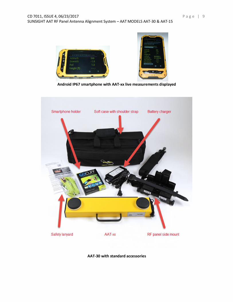
Android IP67 smartphone with AAT-xx live measurements displayed
AAT-30 with standard accessories

CD 7011, ISSUE 4, 06/23/2017 P a g e | 1 0 SUNSIGHT AAT RF Panel Antenna Alignment System – AAT MODELS AAT-30 & AAT-15
Typical Work Flowchart

CD 7011, ISSUE 4, 06/23/2017 P a g e | 1 1 SUNSIGHT AAT RF Panel Antenna Alignment System – AAT MODELS AAT-30 & AAT-15
Order of Operations 1) Charge the AAT and Handheld Controller. 2) Power on the AAT and Handheld Controller. 3) Connect the Handheld Controller to the AAT’s Wi-Fi hotspot. See Page 11 & 12 4) Create profiles for antennas to be aligned - optional. See Page 15 5) Run the AAT on the ground at the job site and verify azimuth acquisition (blue AZM LED solid). 6) Power off the AAT before climbing. This will save time on the tower. 7) Secure mount to the antenna to be measured. See Page 13 8) Secure the AAT to its mount. 9) Power on the AAT and Handheld Controller. 10) Connect the Handheld Controller to the AAT’s Wi-Fi hotspot.
11) Align the antenna and capture data. See Page 16
12) Generate reports. See Page 21-23
Connecting the Handheld Controller to the AAT
Android and Sunsight IP67 Smartphone
1) Power on the AAT.
2) Power on and enable Wi-Fi on the Android device being used to communicate with the AAT. See
User’s Manual for device-specific instructions. For most Android devices:
a. Click “Settings”
b. Click “Wi-Fi”
c. Enable Wi-Fi, if necessary.
d. Connect to Wi-Fi hotspot AAT 901xxxx
e. Once connected, the green Link LED on the AAT keypad will illuminate.
3) Log in to the AAT by clicking the AAT shortcut on the Android’s (if purchased with AAT)
homepage, or by opening a web browser and navigating to 192.168.0.50.
4) NOTE: If the Android device is taken out of range of the AAT Wi-Fi broadcast, the device may
automatically attempt to connect to another Wi-Fi network or the cell network. This feature
may be disabled by the user, if desired. See device owner’s manual for more information.
iOS devices (iPhone and iPad)
1) Power on the AAT.
2) Power on the iOS device to be used with the AAT.
3) On the iOS device, click “Settings”
4) Click “Wi-Fi” and enable, if necessary.
5) Choose network “AAT 901xxxx” where the x’s represent the serial number of the AAT.
6) Log in to the AAT by opening a web browser and navigating to 192.168.0.50.
7) NOTE: If the iOS device is taken out of range of the AAT Wi-Fi broadcast, the device may
automatically attempt to connect to another Wi-Fi network or the cell network. This feature
may be disabled by the user, if desired. See device owner’s manual for more information.
Sunsight Ruggedized tablet (P/N 4200) NOTE: Reports with embedded photographs require use of the Sunsight Ruggedized tablet (P/N 4200).
This feature is not available for customer-supplied devices.
CD 7011, ISSUE 4, 06/23/2017 P a g e | 1 2 SUNSIGHT AAT RF Panel Antenna Alignment System – AAT MODELS AAT-30 & AAT-15
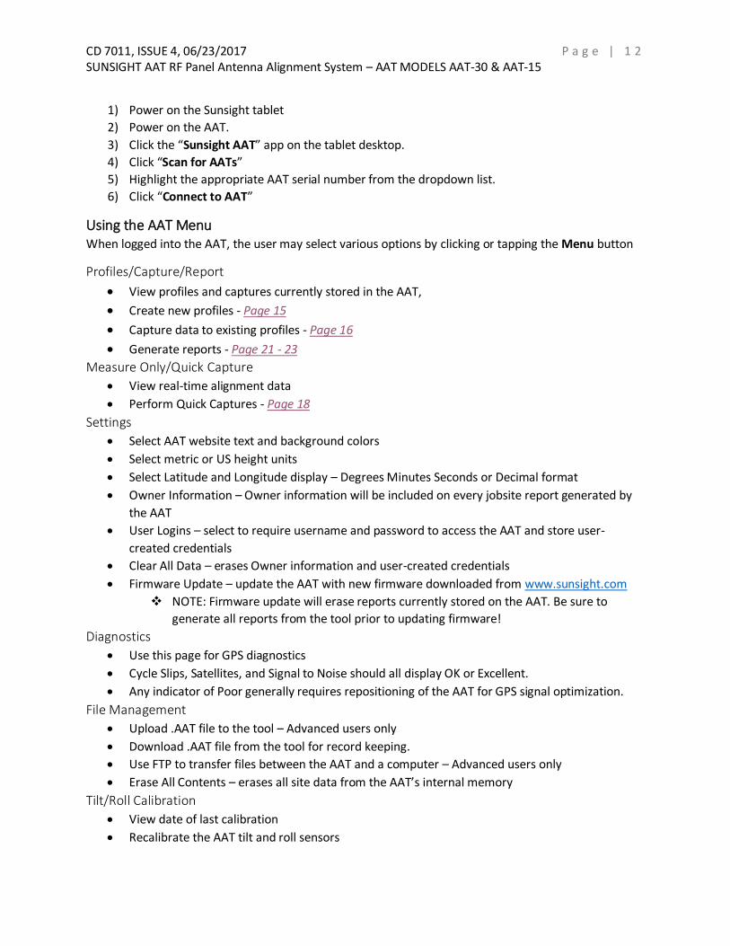
1) Power on the Sunsight tablet
2) Power on the AAT.
3) Click the “Sunsight AAT” app on the tablet desktop.
4) Click “Scan for AATs”
5) Highlight the appropriate AAT serial number from the dropdown list.
6) Click “Connect to AAT”
Using the AAT Menu When logged into the AAT, the user may select various options by clicking or tapping the Menu button
Profiles/Capture/Report
View profiles and captures currently stored in the AAT,
Create new profiles - Page 15
Capture data to existing profiles - Page 16
Generate reports - Page 21 - 23
Measure Only/Quick Capture
View real-time alignment data
Perform Quick Captures - Page 18
Settings
Select AAT website text and background colors
Select metric or US height units
Select Latitude and Longitude display – Degrees Minutes Seconds or Decimal format
Owner Information – Owner information will be included on every jobsite report generated by
the AAT
User Logins – select to require username and password to access the AAT and store user-
created credentials
Clear All Data – erases Owner information and user-created credentials
Firmware Update – update the AAT with new firmware downloaded from www.sunsight.com
NOTE: Firmware update will erase reports currently stored on the AAT. Be sure to
generate all reports from the tool prior to updating firmware!
Diagnostics
Use this page for GPS diagnostics
Cycle Slips, Satellites, and Signal to Noise should all display OK or Excellent.
Any indicator of Poor generally requires repositioning of the AAT for GPS signal optimization.
File Management
Upload .AAT file to the tool – Advanced users only
Download .AAT file from the tool for record keeping.
Use FTP to transfer files between the AAT and a computer – Advanced users only
Erase All Contents – erases all site data from the AAT’s internal memory
Tilt/Roll Calibration
View date of last calibration
Recalibrate the AAT tilt and roll sensors

CD 7011, ISSUE 4, 06/23/2017 P a g e | 1 3 SUNSIGHT AAT RF Panel Antenna Alignment System – AAT MODELS AAT-30 & AAT-15
See Page 26 or visit https://www.sunsight.com/index.php/training for calibration check and
recalibration instructions.
Help
View the Quick Start Guide originally shipped with every AAT. The Quick Start Guide and RF
Panel Alignment instructions are also available for download at
https://www.sunsight.com/index.php/support
Aligning Standard RF Panel Antennas NOTE: Due to its physical size, the AAT-08 is not recommended for RF panel alignment.
1) Ensure AAT and Wi-Fi device batteries are sufficiently charged prior to field use. 2) Secure the AAT panel side-mount to the antenna to be measured. The grips and strap buckle will
be perpendicular to the backplane of the antenna. See Figures 1a & 1b
a. Ensure mount is positioned as high on the antenna as possible. THIS IS CRITICAL! b. Loop mount strap around antenna, then under mount crossbar. BE SURE STRAP IS
POSITIONED UNDER CROSS BAR! c. Feed strap end into ratchet buckle, then pull slack from strap. d. Use the ratchet buckle to tighten strap. 2 – 3 clicks is usually sufficient to secure mount.
DO NOT OVERTIGHTEN! e. Ensure mount sits square on back/side of antenna. Adjust mount position as necessary.
Figure 1a

CD 7011, ISSUE 4, 06/23/2017 P a g e | 1 4 SUNSIGHT AAT RF Panel Antenna Alignment System – AAT MODELS AAT-30 & AAT-15
Figure 1b
3) Secure AAT to mount by positioning upper lip of mounting rail on back of AAT into mount grip, then rotate AAT into to security latch. User should feel AAT “click” into position. Tighten both mount thumbscrews.
4) Secure AAT and mount to structure with the included safety lanyard. Attach lanyard to AAT handle and through provided loop in mount strap. See Figure 2
Figure 2
***ALWAYS USE THE INCLUDED SAFETY LANYARD TO PROTECT MOUNT AND AAT FROM ACCIDENTAL FALLS***
5) Power on the AAT. 6) Power on and enable Wi-Fi on the Handheld Device being used to communicate with the AAT. 7) Log in to the AAT – See Pages 11 & 12 for device-specific instructions.
CD 7011, ISSUE 4, 06/23/2017 P a g e | 1 5 SUNSIGHT AAT RF Panel Antenna Alignment System – AAT MODELS AAT-30 & AAT-15
Capturing Alignment Data 1) To capture alignment data, the user may choose to:
a. Create a new profile to capture alignment data – Proceed to Step 2 b. Capture data to a previously created profile – Proceed to Step 3 c. Use the “Quick Capture” feature – Proceed to Step 4
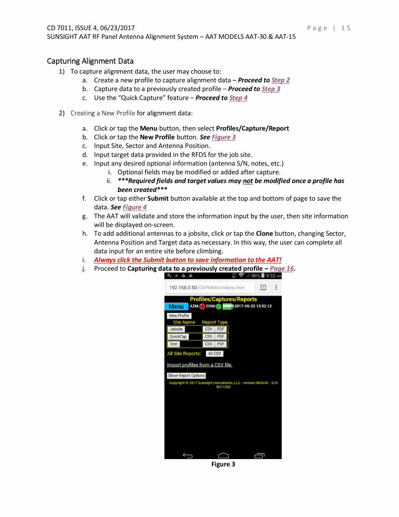
2) Creating a New Profile for alignment data:
a. Click or tap the Menu button, then select Profiles/Capture/Report b. Click or tap the New Profile button. See Figure 3 c. Input Site, Sector and Antenna Position. d. Input target data provided in the RFDS for the job site. e. Input any desired optional information (antenna S/N, notes, etc.)
i. Optional fields may be modified or added after capture. ii. ***Required fields and target values may not be modified once a profile has
been created*** f. Click or tap either Submit button available at the top and bottom of page to save the
data. See Figure 4 g. The AAT will validate and store the information input by the user, then site information
will be displayed on-screen. h. To add additional antennas to a jobsite, click or tap the Clone button, changing Sector,
Antenna Position and Target data as necessary. In this way, the user can complete all data input for an entire site before climbing.
i. Always click the Submit button to save information to the AAT! j. Proceed to Capturing data to a previously created profile – Page 16.
Figure 3

CD 7011, ISSUE 4, 06/23/2017 P a g e | 1 6 SUNSIGHT AAT RF Panel Antenna Alignment System – AAT MODELS AAT-30 & AAT-15
The user may perform as many captures to a specific profile (antenna) as desired. The reports generated by the AAT will always display only the First - “As you found it” - and Final - “As you left it” - captures stored to a profile. This allows the user to capture the alignment of an antenna prior to work being performed, and again after aligning the antenna without the need to create separate profiles for “before” and “after” work.
3) Capturing data to a previously created profile:
a. Click or tap the Menu button, then select Profiles/Capture/Report. b. Click or tap the jobsite button to be captured. See Figure 3 c. Click or tap the Prev Profile and Next Profile buttons to scroll through available antenna
positions stored under the jobsite.
Figure 4
d. Click or tap the Full Capture button to capture all alignment data or select Scope
Capture to capture azimuth only. i. NOTE: The Scope Capture function is intended for use with the Sunsight
Azimuth Scope Kit, and will record azimuth only. ii. NOTE: Selecting Scope Capture will not allow tilt, roll or height measurements
to be saved, although these measurements will still be displayed on-screen! e. At the top of the page, ensure Orientation is correct. Click the Apply button to save any
change to Orientation. See Figure 5

CD 7011, ISSUE 4, 06/23/2017 P a g e | 1 7 SUNSIGHT AAT RF Panel Antenna Alignment System – AAT MODELS AAT-30 & AAT-15
i. Orientation is as viewed from behind the antenna. The handle side of the AAT is considered the front of the device. Example: If, from behind the antenna, the AAT handle points left, orientation must be set to “AAT Faces Left.”
ii. Incorrect orientation will provide azimuth values +/- 90° or 180° above or below expected. Recheck orientation.
Figure 5
f. Align “Actual” measurements on-screen to displayed target values.
i. If capturing AGL height, refer to section - Using LASER rangefinder (LRF) to capture Above Ground Level (AGL) height – Page 24
ii. If no target values were input during profile creation, refer to RFDS for targets. iii. Select the required capture delay time by clicking or tapping the appropriate
button. See Figure 5 iv. Extended delay time may be used to allow climber time to remove his/her
weight from antenna boom, or in instances of heavy wind buffeting. g. Review captured data displayed on-screen. h. Click or tap the Save button to save captured data to the AAT.
i. If captured data does not agree with target data, the user may choose to Reject the capture and perform Steps 3e – 3h to capture new measurements.
Add photos to the capture record
*Available only with the Sunsight Ruggedized tablet (P/N 4200) and using the Sunsight app* ii. After the capture has been saved, the user will be prompted to add photos.
1. Select “Yes” to add photos to the capture or “No” to continue. 2. Users may add up to two photographs per capture.

CD 7011, ISSUE 4, 06/23/2017 P a g e | 1 8 SUNSIGHT AAT RF Panel Antenna Alignment System – AAT MODELS AAT-30 & AAT-15
a. NOTE: If performing “First” and “Final” captures on an antenna, only the second, or “Final,” set of photographs will be stored to the report.
3. When generating reports, photographs stored to the capture record will render with all alignment data embedded in the photo.
i. Repeat Steps 3c – 3i for all antennas to be aligned under selected jobsite.
4) Using the “Quick Capture” feature: a. Click or tap Menu, then select Measure Only. b. On the live measurements page click or tap the Quick Capture button. c. After the timer countdown, captured information will be displayed. d. Click or tap the Next button to input site information and save the capture to the AAT
(See Figure 7) or select Reject to return to the live measurements page to begin again. e. Input Site, Sector and Antenna Position.
i. NOTE: Target alignment data cannot be input when using the Quick Capture feature
f. Click or tap either Submit button located at the top and bottom of the page to save the captured data.
Add photos to the capture record
*Available only with the Sunsight Ruggedized tablet (P/N 4200) and using the Sunsight app* i. After the capture has been saved, the user will be prompted to add photos.
1. Select “Yes” to add photos to the capture or “No” to continue. 2. Users may add up to two photographs per capture.
a. NOTE: If performing “First” and “Final” captures on an antenna, only the second, or “Final,” set of photographs will be stored to the report.
3. When generating reports, photographs stored to the capture record will render with all alignment data embedded in the photo. See Figure 6 for examples.
5) Power down AAT and Wi-Fi device. Remove mount from antenna by lifting the ratchet strap buckle release. See Figure 1a & 1b
6) Secure all hardware for transport.

CD 7011, ISSUE 4, 06/23/2017 P a g e | 1 9 SUNSIGHT AAT RF Panel Antenna Alignment System – AAT MODELS AAT-30 & AAT-15

CD 7011, ISSUE 4, 06/23/2017 P a g e | 2 0 SUNSIGHT AAT RF Panel Antenna Alignment System – AAT MODELS AAT-30 & AAT-15
Figure 6 Photo examples from AAT reports
CD 7011, ISSUE 4, 06/23/2017 P a g e | 2 1 SUNSIGHT AAT RF Panel Antenna Alignment System – AAT MODELS AAT-30 & AAT-15
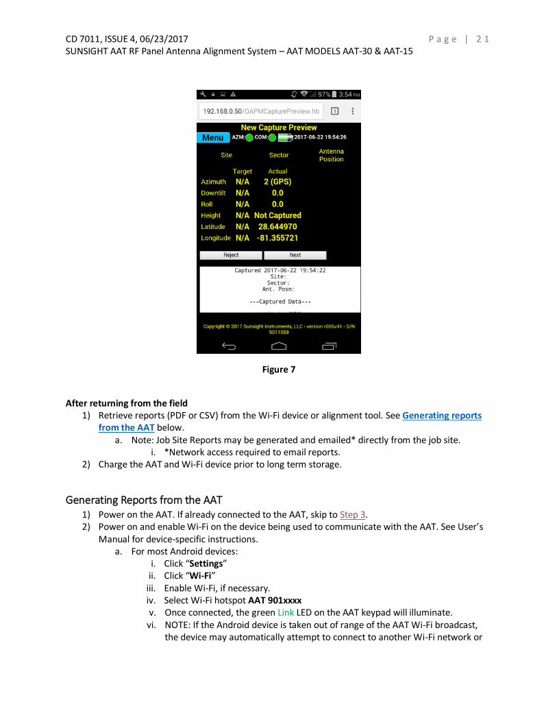
Figure 7
After returning from the field
1) Retrieve reports (PDF or CSV) from the Wi-Fi device or alignment tool. See Generating reports from the AAT below.
a. Note: Job Site Reports may be generated and emailed* directly from the job site. i. *Network access required to email reports.
2) Charge the AAT and Wi-Fi device prior to long term storage.
Generating Reports from the AAT 1) Power on the AAT. If already connected to the AAT, skip to Step 3. 2) Power on and enable Wi-Fi on the device being used to communicate with the AAT. See User’s
Manual for device-specific instructions. a. For most Android devices:
i. Click “Settings” ii. Click “Wi-Fi” iii. Enable Wi-Fi, if necessary. iv. Select Wi-Fi hotspot AAT 901xxxx v. Once connected, the green Link LED on the AAT keypad will illuminate. vi. NOTE: If the Android device is taken out of range of the AAT Wi-Fi broadcast,
the device may automatically attempt to connect to another Wi-Fi network or

CD 7011, ISSUE 4, 06/23/2017 P a g e | 2 2 SUNSIGHT AAT RF Panel Antenna Alignment System – AAT MODELS AAT-30 & AAT-15
the cell network. This feature may be disabled by the user, if desired. See device owner’s manual for more information.
b. For Windows operating systems: i. Ensure Wi-Fi is enabled. ii. Click the Wi-Fi icon in lower right computer screen. iii. Select Wi-Fi hotspot AAT 901xxxx iv. Click “Connect” v. Once connected, the green Link LED on the AAT keypad will illuminate.
c. For iOS devices (iPhone and iPad)
i. Power on the AAT. ii. Power on the iOS device to be used with the AAT. iii. On the iOS device, click “Settings” iv. Click “Wi-Fi” and enable, if necessary. v. Choose network “AAT 901xxxx” where the x’s represent the serial number of
the AAT. vi. Once connected, the green Link LED on the AAT keypad will illuminate.
vii. NOTE: If the iOS device is taken out of range of the AAT Wi-Fi broadcast, the device may automatically attempt to connect to another Wi-Fi network or the cell network. This feature may be disabled by the user, if desired. See device owner’s manual for more information.
3) Log in to the AAT by clicking the AAT shortcut on the Android’s (if purchased with AAT) homepage, or by opening a web browser and navigating to 192.168.0.50.
a. Google Chrome is recommended, but any web browser may be used.
4) Click or tap Menu, then select Profiles/Capture/Report. 5) Locate the site name for the report to be generated. See Figure 8 6) Select information to be included in the site report by clicking Show Report Options.
a. Latitude/Longitude, Tilt, Roll, AZM, and AGL are defaulted to “On.” b. Individual options may be enabled or disabled by clicking the checkbox next to the
option. c. WGS84 is the standard Latitude/Longitude format. If the unit is equipped with optional
grids (British National Grid, French Lambert II, etc.), one additional grid may be selected for inclusion in the site report.
7) The user may choose from two download formats: a. Click PDF to download and save a PDF version of the captured data. This is the simplest
method of report generation – See Step 8 b. Click CSV to save the report in Comma Separated Values format – to export capture
information to a spreadsheet, such as Microsoft Excel – See Step 9 8) Selecting PDF allows the user to download the site report in PDF format.
a. If using Google Chrome, selecting PDF will automatically download the report to the Wi-Fi device’s Downloads folder.
b. Other browsers may require input from the user to Open or Save the PDF. The user must save the PDF to the Wi-Fi device in order to keep a local copy.

CD 7011, ISSUE 4, 06/23/2017 P a g e | 2 3 SUNSIGHT AAT RF Panel Antenna Alignment System – AAT MODELS AAT-30 & AAT-15
9) Selecting CSV allows the user to download capture information in a format compatible with Microsoft Excel and similar spreadsheet programs.
a. Selecting CSV in Google Chrome will automatically download the file to the Wi-Fi device’s Downloads folder.
b. Other browsers may require input from the user to Open or Save the CSV file. The user must save the CSV file in order to keep a local copy.
Figure 8
Notes regarding AAT report generation and retrieval:
All stored capture data remains in the AAT’s internal memory, even after reports are generated.
Reports may be generated repeatedly and on multiple Wi-Fi devices, if desired.
Capture information is only deleted if the user deletes an individual profile or selects the Erase function located at the bottom of the AAT’s File Management internal web page.
As the AAT creates a backup database file every time a modification is made (profile added, capture performed, etc.), it is recommended that the internal SD card be erased periodically.
CD 7011, ISSUE 4, 06/23/2017 P a g e | 2 4 SUNSIGHT AAT RF Panel Antenna Alignment System – AAT MODELS AAT-30 & AAT-15
Adding photographs to the reports will increase the amount of space used on the internal SD card and will necessitate more frequent SD card erasure.
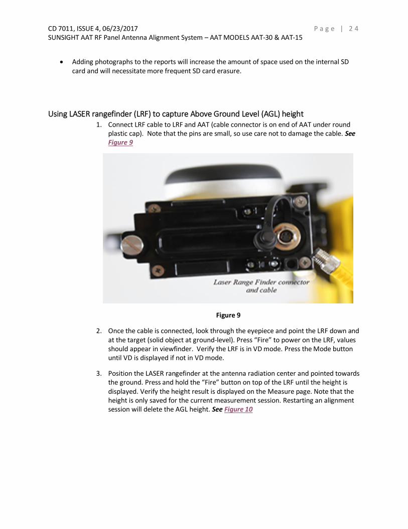
Using LASER rangefinder (LRF) to capture Above Ground Level (AGL) height 1. Connect LRF cable to LRF and AAT (cable connector is on end of AAT under round
plastic cap). Note that the pins are small, so use care not to damage the cable. See Figure 9
Figure 9
2. Once the cable is connected, look through the eyepiece and point the LRF down and at the target (solid object at ground-level). Press “Fire” to power on the LRF, values should appear in viewfinder. Verify the LRF is in VD mode. Press the Mode button until VD is displayed if not in VD mode.
3. Position the LASER rangefinder at the antenna radiation center and pointed towards the ground. Press and hold the “Fire” button on top of the LRF until the height is displayed. Verify the height result is displayed on the Measure page. Note that the height is only saved for the current measurement session. Restarting an alignment session will delete the AGL height. See Figure 10

CD 7011, ISSUE 4, 06/23/2017 P a g e | 2 5 SUNSIGHT AAT RF Panel Antenna Alignment System – AAT MODELS AAT-30 & AAT-15
Figure 10
4. Remove cable/LRF and stow in a safe place. Note that the height is only saved for the current measurement session. Restarting an alignment session will delete the AGL height.
5. Return to Capturing Alignment Data Step 3-f-ii (Page 16) to continue RF Panel Alignment.

CD 7011, ISSUE 4, 06/23/2017 P a g e | 2 6 SUNSIGHT AAT RF Panel Antenna Alignment System – AAT MODELS AAT-30 & AAT-15
Checking tilt and roll calibration Sunsight strongly recommends that users periodically check the tilt and roll calibration of the AAT’s
internal sensors. The frequency with which these checks should be performed will depend on how often
the AAT is used and how it is cared for. Calibration checks should be performed monthly, at a minimum.
The AAT does not require return to Sunsight for calibration.
1) To check calibration, place the AAT on a flat surface.
2) Power on and log in to the AAT.
3) On the Measure Only/Quick Capture page, set the Orientation to “Back.”
4) Note the tilt and roll measurements displayed - it may help to write them down.
5) Turn the AAT to face the opposite direction and note the tilt and roll measurements
displayed.
6) Compare the two sets of values – the numbers should be the same, but with opposite
signs – I.E. if tilt displays 0.2°, it should display -0.2° when facing the opposite direction.
7) If the measurements are as described above, within +/- 0.1°, the AAT is calibrated
8) If measurements are not as described above, within +/- 0.1°, calibrate the AAT’s tilt and
roll sensors by following the prompts on the Tilt/Roll Calibration page.
Troubleshooting Checking current firmware version
Log in to the AAT (See Page 10 & 11). Scroll to the bottom of any AAT webpage, where
the user can find the AAT serial number and firmware version currently installed.
The AAT will not power on
Ensure that the onboard LiFePO4 battery is charged using only the approved charger.
Use of any other charger or power supply may cause insufficient charge, overcharge, or
electrical damage to the unit.
Webpages not available
Ensure your Handheld Controller is connected to Wi-Fi hotspot AAT 901xxxx, where the
x’s represent the serial number of the AAT. Serial number decals are located on the back
of the unit, next to the mounting rail.
With the Handheld Controller connected to the AAT’s Wi-Fi hotspot, open a web
browser and navigate to 192.168.0.50
The AAT will not display azimuth
GPS is line-of-sight technology and, as such, both GPS antennas at the top of the AAT
must have as clear a view of the sky as possible.
The AAT should always be mounted as high on the antenna to be measured as possible.
Use the indicators on the AAT’s Diagnostic page to help determine optimal placement.

CD 7011, ISSUE 4, 06/23/2017 P a g e | 2 7 SUNSIGHT AAT RF Panel Antenna Alignment System – AAT MODELS AAT-30 & AAT-15
Use and care of the Sunsight AAT The AAT utilizes state-of-the-art GPS/GLONASS technology in order to provide highly accurate
azimuth calculations. GPS and GLONASS are line-of-sight technologies. For optimal results, the GPS/GLONASS antennas at the top of the AAT should be offered the best “view” of the sky possible. Physical obstructions over either antenna may result in difficult or no-azimuth conditions. Position the AAT so as to eliminate or minimize physical obstructions.
The AAT and its accessories are weather resistant, not water-proof! Do no immerse or submerge the AAT in liquid of any type. All access doors and caps must be in good working order and secured while the AAT and its accessories are in use, especially in inclement weather.
Do not store the AAT or its accessories in a wet case. Allow the case(s) to air dry prior to storing the AAT and its accessories.
The AAT housing is fabricated of aluminum for durability, but still contains highly sensitive electronic components. Avoid sharp impacts and drops.
The AAT and its accessories contain no user-serviceable components. Do not attempt to disassemble the AAT for any reason. Unauthorized disassembly may result in component damage and warranty termination.
Sunsight strives to provide the best user experience possible with our products. To that end, we
continue to develop hardware and software solutions to meet the needs of our customers.
Sunsight will periodically issue firmware updates to enhance performance and function of our
products. To receive update notifications, please register your AAT at:
https://www.sunsight.com/index.php/register-aat. Your information is never shared or sold and
is used only by Sunsight to track user updates.
For questions regarding use or care of the AAT and its accessories, please contact Sunsight Instruments
Technical Support. Live technical support is available Monday – Friday from 9:00am to 6:00pm Eastern.
1-321-244-9443 x2

CD 7011, ISSUE 4, 06/23/2017 P a g e | 2 8 SUNSIGHT AAT RF Panel Antenna Alignment System – AAT MODELS AAT-30 & AAT-15
Glossary AAT – The Sunsight Instruments AntennAlign Alignment Tool is a self-contained measuring
device that can be used to measure azimuth, tilt, roll, latitude, longitude, and height of the
device it is attached to. The primary use of the AAT is to provide and record the necessary
measurements to allow a user to align devices (example: cellular panel antennas).
Capture - A capture is the action of recording measurements to the AAT. Typically, the tower
technician will adjust the antenna to the required alignment values and capture (record) the
results. The captured data is then used to generate reports.
Downtilt – See “Tilt”
Embedded Website - The AAT is accessed through its Embedded (built-in) Website. Connect
your Wi-Fi device to the AAT’s access point, or “hot spot.” Then, using the device’s web browser,
enter the AAT’s web address to access the AAT’s website. All input and output to and from the
AAT is accessed in this way.
GPS and GLONASS - GPS and GLONASS, also referred to as GNSS, are both satellite-based
positioning systems that are used by the AAT to determine exact latitude and longitude of the
AAT. Also, and most importantly, the satellites are used to determine the azimuth for the AAT.
Handheld Controller – The AAT can be accessed by most any smartphone, tablet or laptop
supporting standard Wi-Fi (802.11b/g/n). No apps or software downloads are required. Connect
the Wi-Fi device to the AAT as you would any access point, or “hot spot”. Then, using a web
browser on the device, type in the AAT’s web address to access the AAT’s embedded
website. All input and output to and from the AAT is accessed in this way.
Plumb – See “Roll”
Profile - A Profile is a set of target alignment data including the site name, sector, and antenna
position. Profiles can be input in advance of doing tower work to minimize data entry on the
tower.
Report - Reports are formatted alignment results that can be created in PDF or CSV formats.
Reports can be created for one individual set of measurements (ex. one antenna) or can be
created for an entire site’s worth of data (several antennas on one report).
RF Panel Antenna - An RF panel antenna is an antenna used for broadcasting cellular signals to
handsets. They are typically mounted on towers or rooftops in a tri-sector configuration.
Roll – Sometimes referred to as “plumb” and measured in degrees. Refers to antenna alignment
in the horizontal plane. A positive or negative roll value indicates the top of the antenna is not
level.
Tilt – Measured in degrees and refers to antenna alignment in the vertical plane. A positive tilt
value indicates the face of the antenna is pointed toward the ground.
Wi-Fi Enabled Device – See “Handheld Controller”