Suncast Corporation Vinyl Gazebo Assembly...
40
Vinyl Gazebo Assembly Instructions For 10’x16’ & 12’x18’ Models Toll Free: 866.768.8465 Hours: 9-5 Monday-Friday EST © Suncast Corporation www.HomePlaceStructures.com Package ships as shown
Transcript of Suncast Corporation Vinyl Gazebo Assembly...
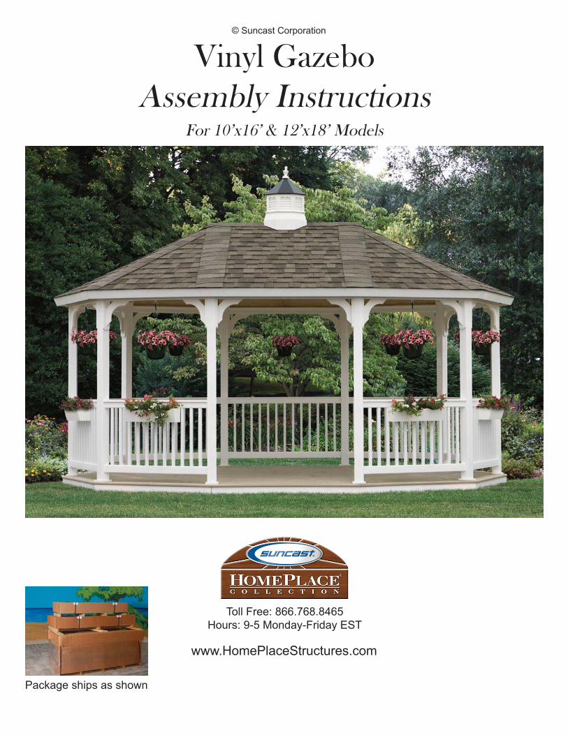
Vinyl GazeboAssembly Instructions
For 10’x16’ & 12’x18’ Models
Toll Free: 866.768.8465Hours: 9-5 Monday-Friday EST
© Suncast Corporation
www.HomePlaceStructures.com
Package ships as shown
Vinyl GazeboAssembly Manual
© Suncast Corporation
revised 05/26/09
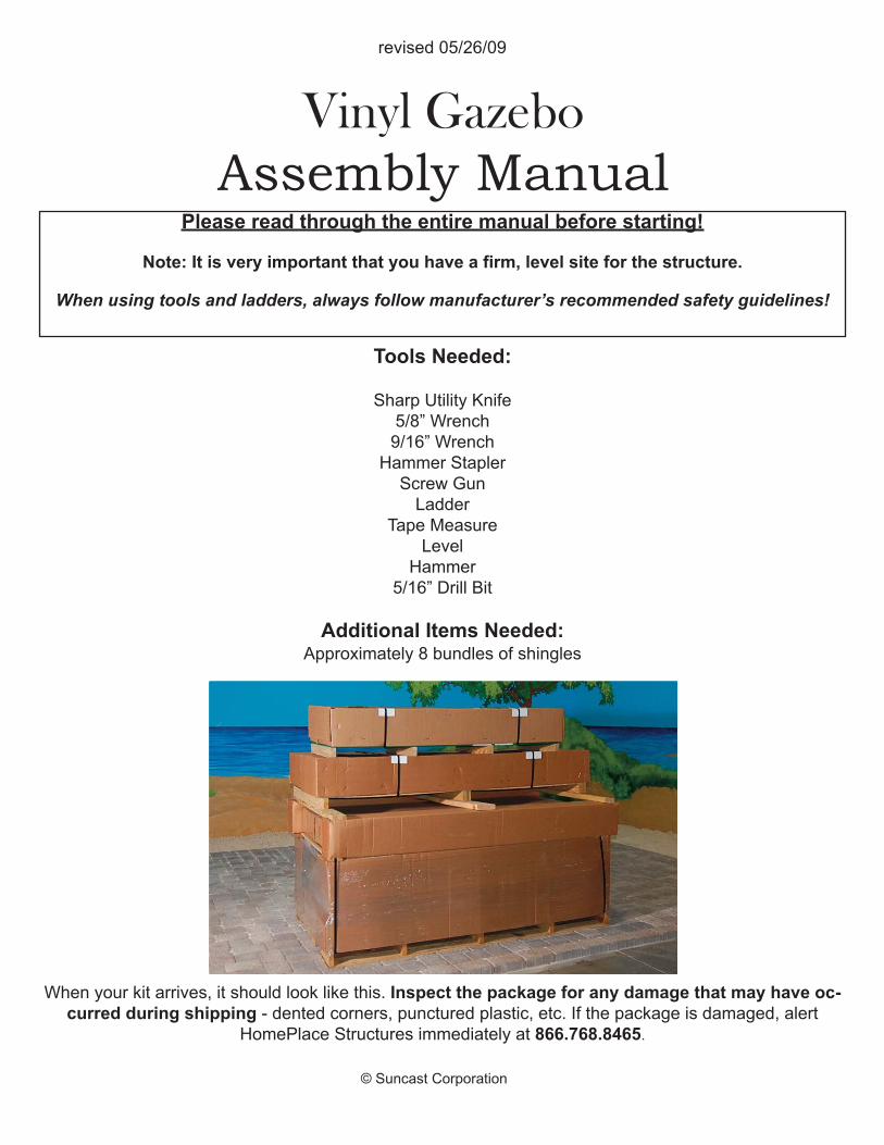
Please read through the entire manual before starting!
Note: It is very important that you have a firm, level site for the structure.
When using tools and ladders, always follow manufacturer’s recommended safety guidelines!
Tools Needed:
Sharp Utility Knife5/8” Wrench9/16” WrenchHammer StaplerScrew GunLadder
Tape MeasureLevelHammer
5/16” Drill Bit
Additional Items Needed:Approximately 8 bundles of shingles
When your kit arrives, it should look like this. Inspect the package for any damage that may have oc-curred during shipping - dented corners, punctured plastic, etc. If the package is damaged, alert
HomePlace Structures immediately at 866.768.8465.

Find
the
asse
mbl
y m
anua
l for
this
pro
duct
at
ww
w.H
omeP
lace
Stru
ctur
es.c
om/m
anua
ls
VIN
YL O
VAL
GAZ
EBO
specification
s
9/07
This
par
tial
ly a
ssem
bled
Vin
yl O
va
l G
aze
bo
kit
incl
udes
rai
ling
sect
ions
, pos
ts, b
race
s,
roof
sec
tion
s, a
nd o
ptio
nal f
loor
sec
tion
s w
ith
mai
nten
ance
-free
floo
r bo
ards
. Mad
e fr
om
the
fines
t mai
nten
ance
-free
mat
eria
ls o
n th
e m
arke
t, th
is g
azeb
o is
bui
lt to
last
for
gene
ra-
tion
s. T
he v
inyl
coa
ting
pre
vent
s co
lor
fadi
ng a
nd th
e ru
st-r
esis
tant
fast
ener
s pr
ovid
e du
rabi
lity
and
stre
ngth
.
36” H
igh
Rai
lings
Fibe
r C
ompo
site
Dec
king
Opt
iona
l Flo
or
Perm
atri
m F
asci
a
Shin
gles
Sup
plie
d B
y C
usto
mer
(9) H
angi
ng P
lant
Hoo
ks
4x4
Vin
yl W
rapp
ed
Woo
d Po
sts
1x6
Tong
ue a
nd G
roov
eYe
llow
Pin
e C
eilin
g
12’X
18’ U
nit S
how
n(1
0’x1
6’ U
nit a
lso
avai
labl
e)
(4) F
low
er B
oxes
9’8”
Tot
al H
eigh
t w
ithou
t opt
iona
l cup
ola
6’8”
Hig
h D
oor
open
ing
Page 04
Page 5
Page 06
Page 7
page 07© Suncast Corporation
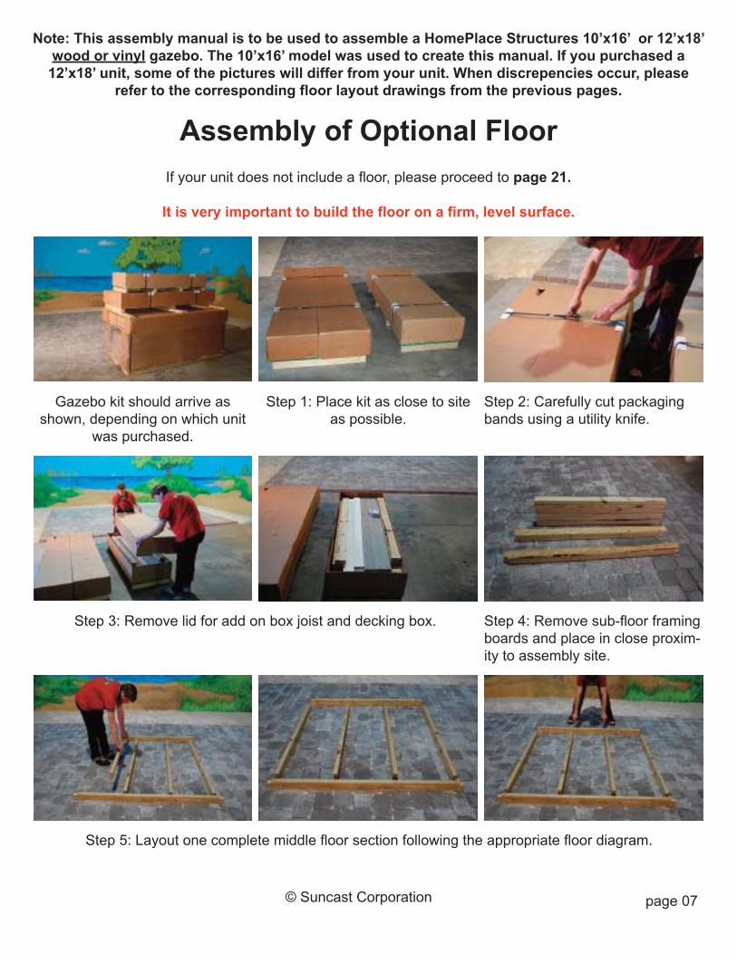
Step 1: Place kit as close to siteas possible.
Gazebo kit should arrive asshown, depending on which unit
was purchased.
Step 2: Carefully cut packagingbands using a utility knife.
Step 3: Remove lid for add on box joist and decking box. Step 4: Remove sub-floor framingboards and place in close proxim-ity to assembly site.
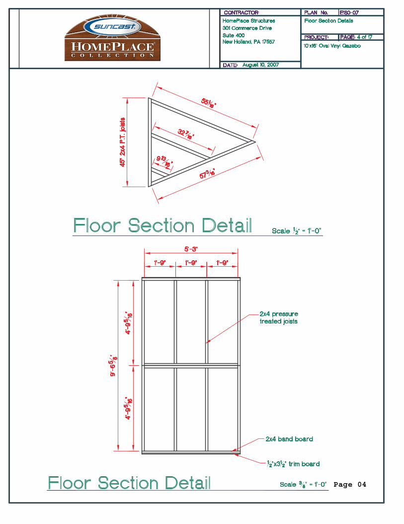
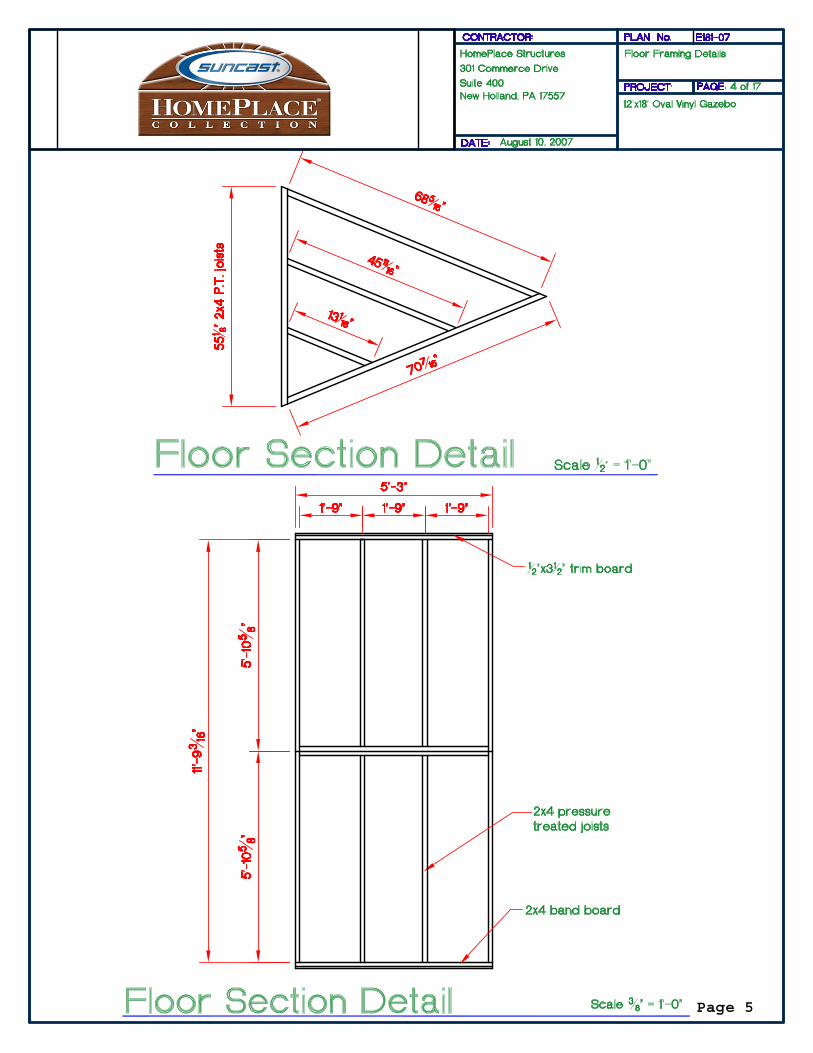
Step 5: Layout one complete middle floor section following the appropriate floor diagram.
Note: This assembly manual is to be used to assemble a HomePlace Structures 10’x16’ or 12’x18’wood or vinyl gazebo. The 10’x16’ model was used to create this manual. If you purchased a12’x18’ unit, some of the pictures will differ from your unit. When discrepencies occur, please
refer to the corresponding floor layout drawings from the previous pages.
Assembly of Optional FloorIf your unit does not include a floor, please proceed to page 21.
It is very important to build the floor on a firm, level surface.
page 08© Suncast Corporation
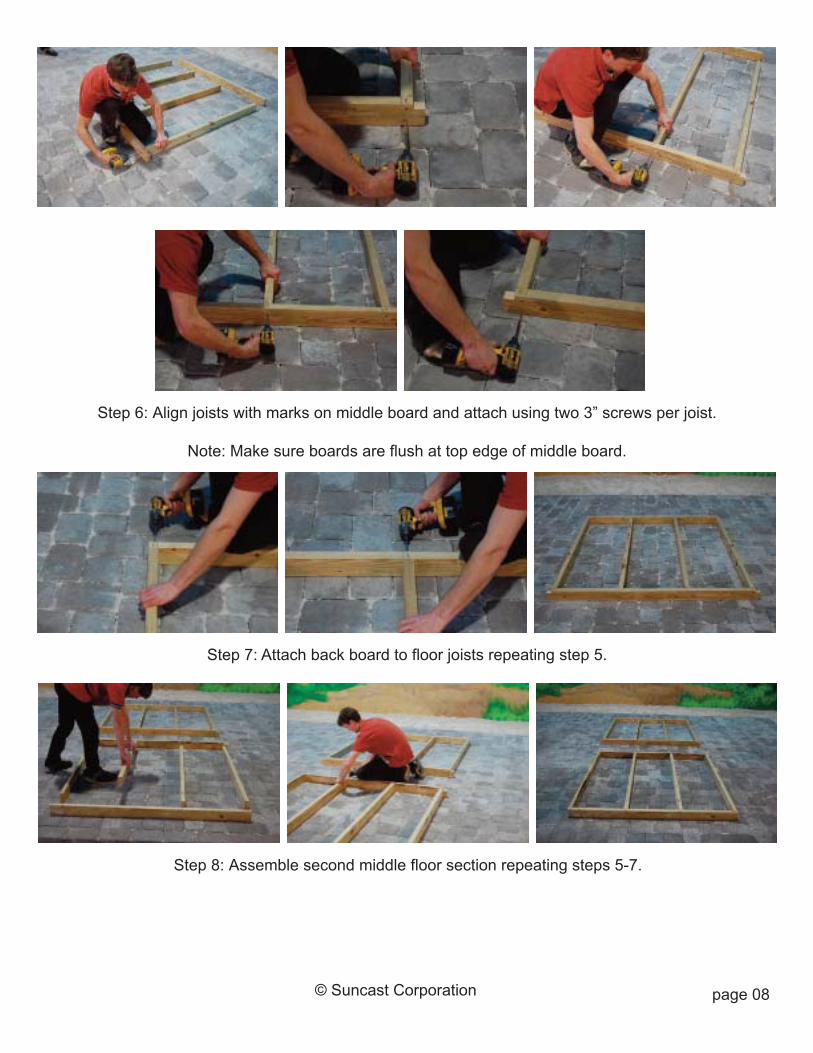
Step 6: Align joists with marks on middle board and attach using two 3” screws per joist.
Note: Make sure boards are flush at top edge of middle board.
Step 7: Attach back board to floor joists repeating step 5.
Step 8: Assemble second middle floor section repeating steps 5-7.
page 09© Suncast Corporation
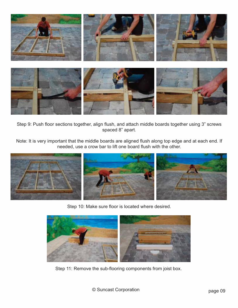
Step 9: Push floor sections together, align flush, and attach middle boards together using 3” screwsspaced 8” apart.
Note: It is very important that the middle boards are aligned flush along top edge and at each end. Ifneeded, use a crow bar to lift one board flush with the other.
Step 10: Make sure floor is located where desired.
Step 11: Remove the sub-flooring components from joist box.
page 10© Suncast Corporation
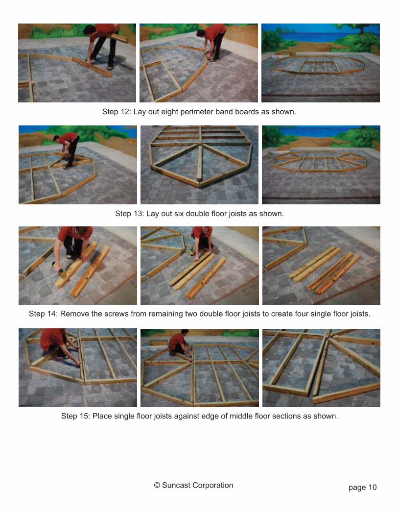
Step 12: Lay out eight perimeter band boards as shown.
Step 13: Lay out six double floor joists as shown.
Step 14: Remove the screws from remaining two double floor joists to create four single floor joists.
Step 15: Place single floor joists against edge of middle floor sections as shown.
page 11© Suncast Corporation
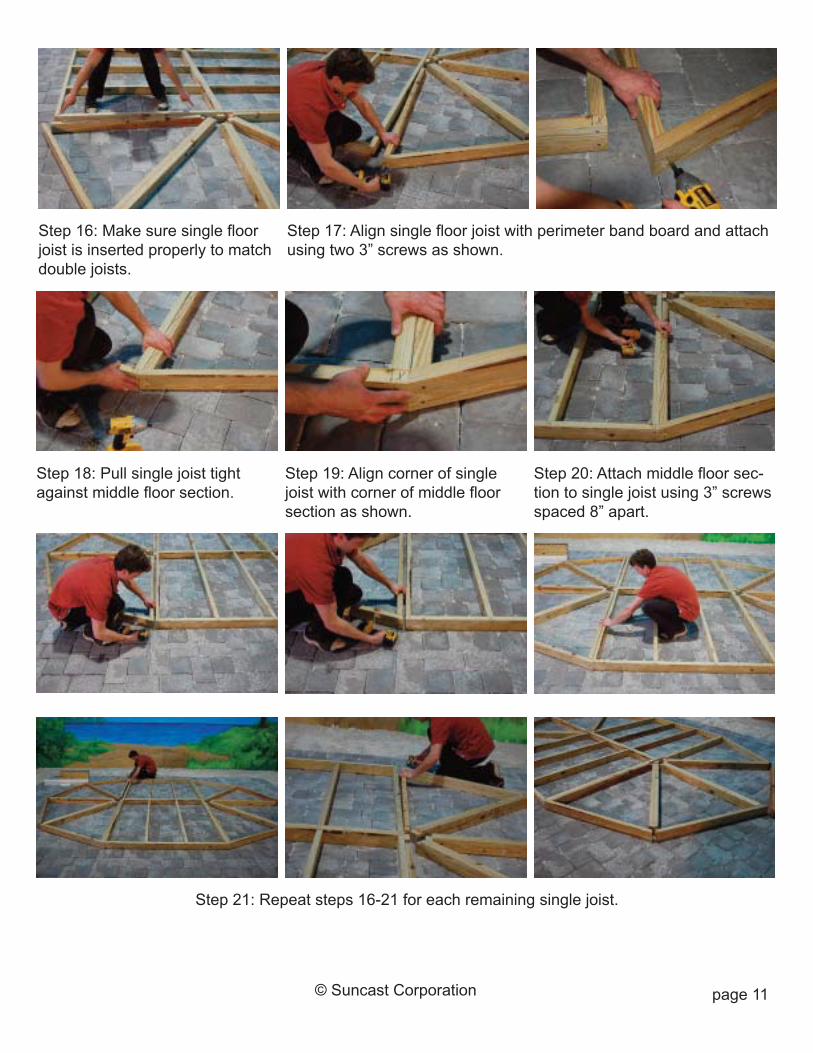
Step 17: Align single floor joist with perimeter band board and attachusing two 3” screws as shown.
Step 16: Make sure single floorjoist is inserted properly to matchdouble joists.
Step 19: Align corner of singlejoist with corner of middle floorsection as shown.
Step 18: Pull single joist tightagainst middle floor section.
Step 20: Attach middle floor sec-tion to single joist using 3” screwsspaced 8” apart.
Step 21: Repeat steps 16-21 for each remaining single joist.
page 12© Suncast Corporation
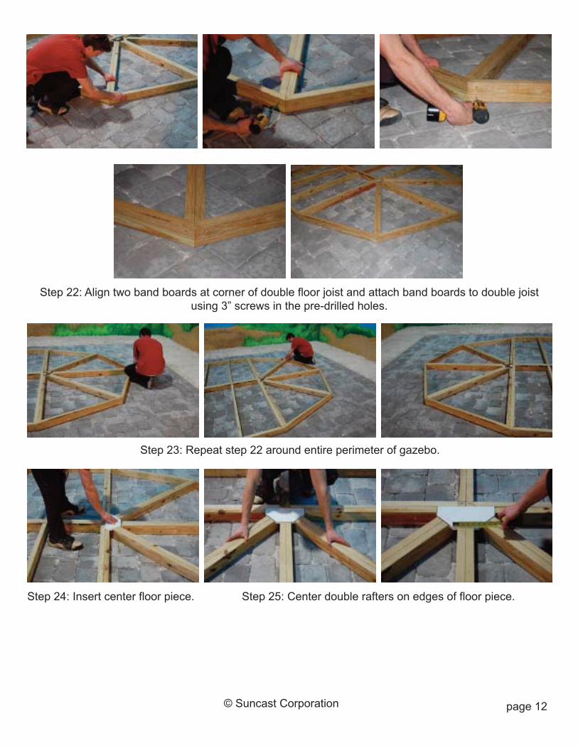
Step 22: Align two band boards at corner of double floor joist and attach band boards to double joistusing 3” screws in the pre-drilled holes.
Step 23: Repeat step 22 around entire perimeter of gazebo.
Step 25: Center double rafters on edges of floor piece.Step 24: Insert center floor piece.
page 13
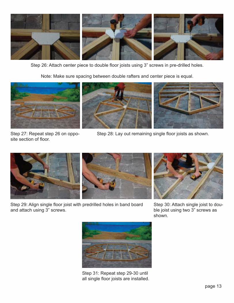
Step 27: Repeat step 26 on oppo-site section of floor.
Step 26: Attach center piece to double floor joists using 3” screws in pre-drilled holes.
Note: Make sure spacing between double rafters and center piece is equal.
Step 29: Align single floor joist with predrilled holes in band boardand attach using 3” screws.
Step 30: Attach single joist to dou-ble joist using two 3” screws asshown.
Step 28: Lay out remaining single floor joists as shown.
Step 31: Repeat step 29-30 untilall single floor joists are installed.

page 14© Suncast Corporation
Step 32: Align front band board trim at corner edges and attach using 1-5/8” screws in pre-drilled holes.Note: Top of trim should be flush with the top of the band board.
Step 34: Install remaining trim pieces around perimeter of gazebo.
Step 33: Align adjacent tim piece at corner and attach using 1-5/8” screws in pre-drilled holes.
page 15
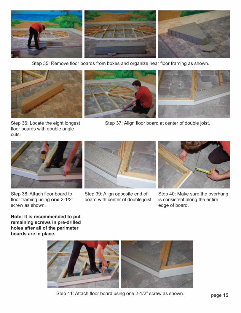
Step 36: Locate the eight longestfloor boards with double anglecuts.
Step 39: Align opposite end ofboard with center of double joist
Step 38: Attach floor board tofloor framing using one 2-1/2”screw as shown.
Note: It is recommended to putremaining screws in pre-drilledholes after all of the perimeterboards are in place.
Step 40: Make sure the overhangis consistent along the entireedge of board.
Step 35: Remove floor boards from boxes and organize near floor framing as shown.
Step 37: Align floor board at center of double joist.
Step 41: Attach floor board using one 2-1/2” screw as shown.
page 16© Suncast Corporation
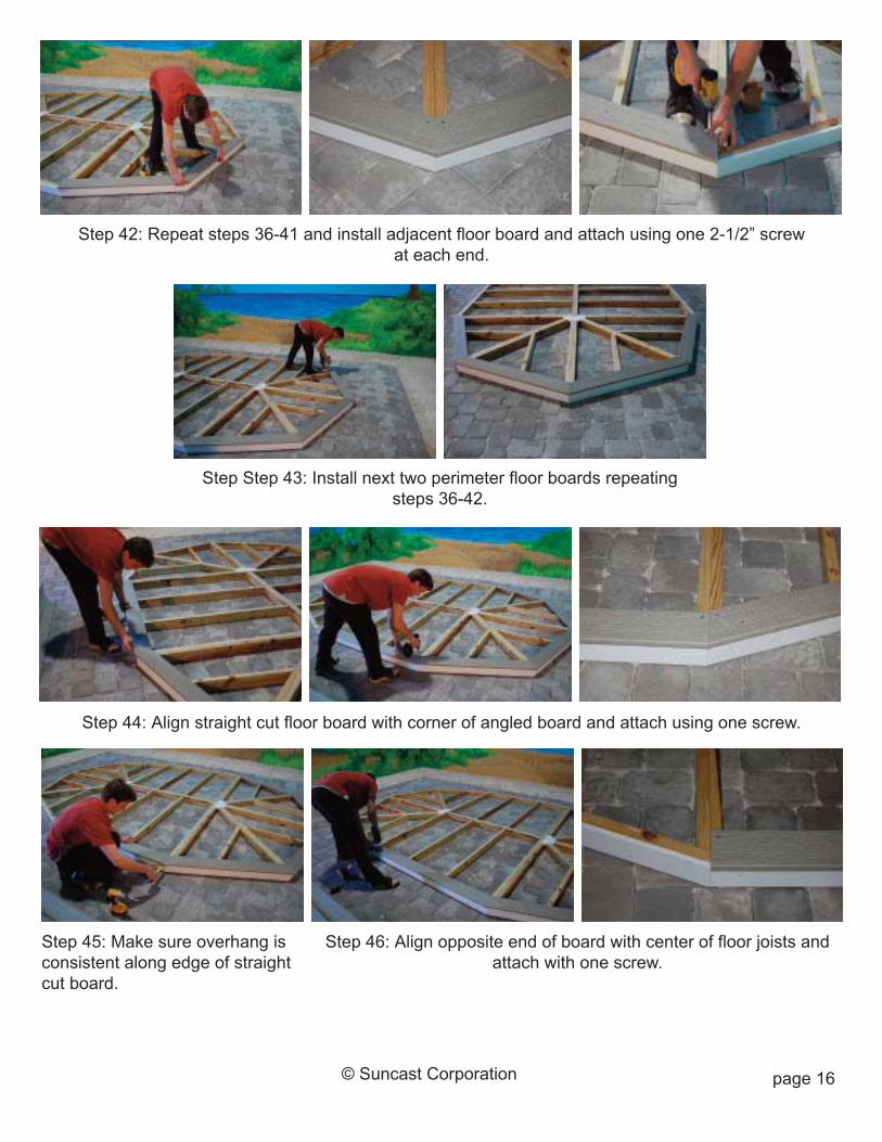
Step 42: Repeat steps 36-41 and install adjacent floor board and attach using one 2-1/2” screwat each end.
Step 44: Align straight cut floor board with corner of angled board and attach using one screw.
Step Step 43: Install next two perimeter floor boards repeatingsteps 36-42.
Step 45: Make sure overhang isconsistent along edge of straightcut board.
Step 46: Align opposite end of board with center of floor joists andattach with one screw.
page 17© Suncast Corporation
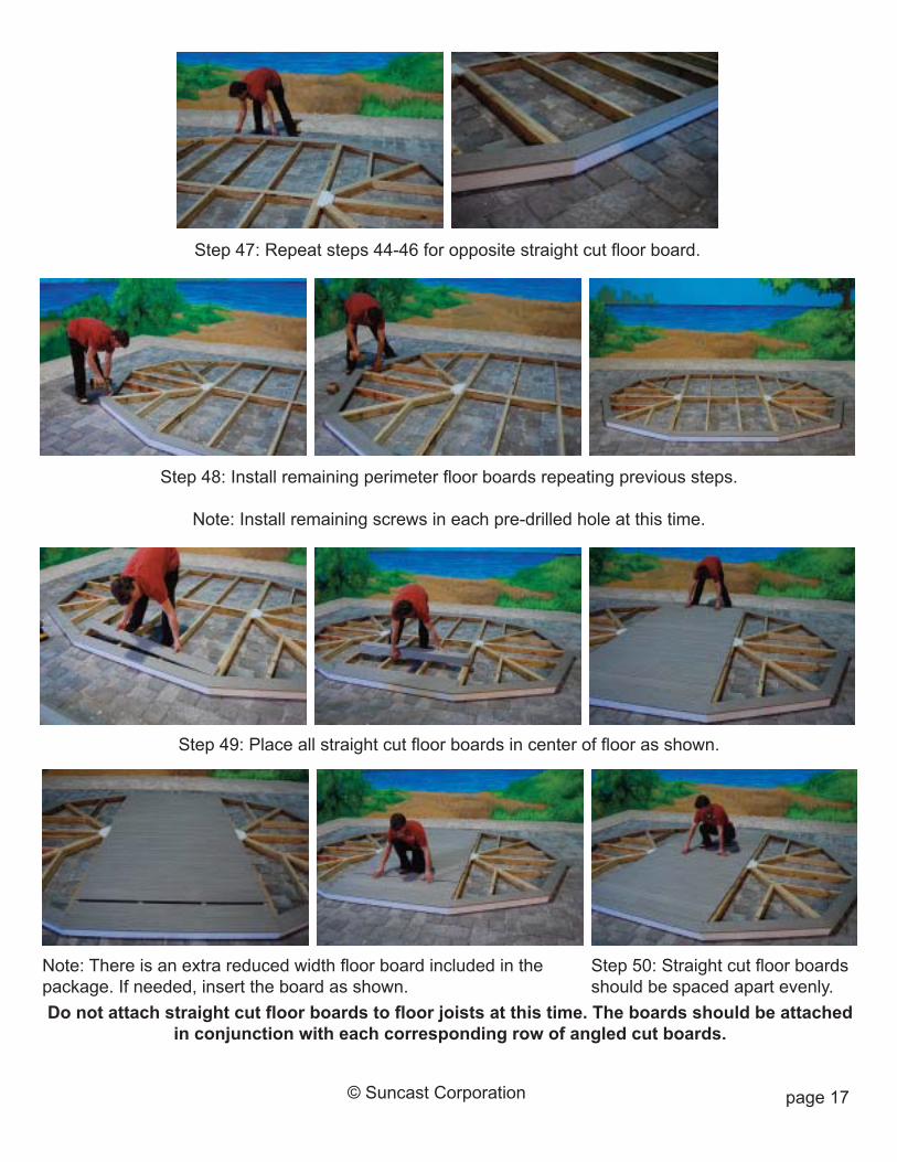
Step 47: Repeat steps 44-46 for opposite straight cut floor board.
Step 48: Install remaining perimeter floor boards repeating previous steps.
Note: Install remaining screws in each pre-drilled hole at this time.
Note: There is an extra reduced width floor board included in thepackage. If needed, insert the board as shown.
Step 50: Straight cut floor boardsshould be spaced apart evenly.
Step 49: Place all straight cut floor boards in center of floor as shown.
Do not attach straight cut floor boards to floor joists at this time. The boards should be attachedin conjunction with each corresponding row of angled cut boards.

page 18© Suncast Corporation
Step 52: Align next straight cut floor board and attach using 2-1/2”screws in pre-drilled holes.
Step 51: Insert next row of angled cut floor boards around entire perimeter of gazebo.
Step 53: Install next four floor boards as shown.
page 19© Suncast Corporation
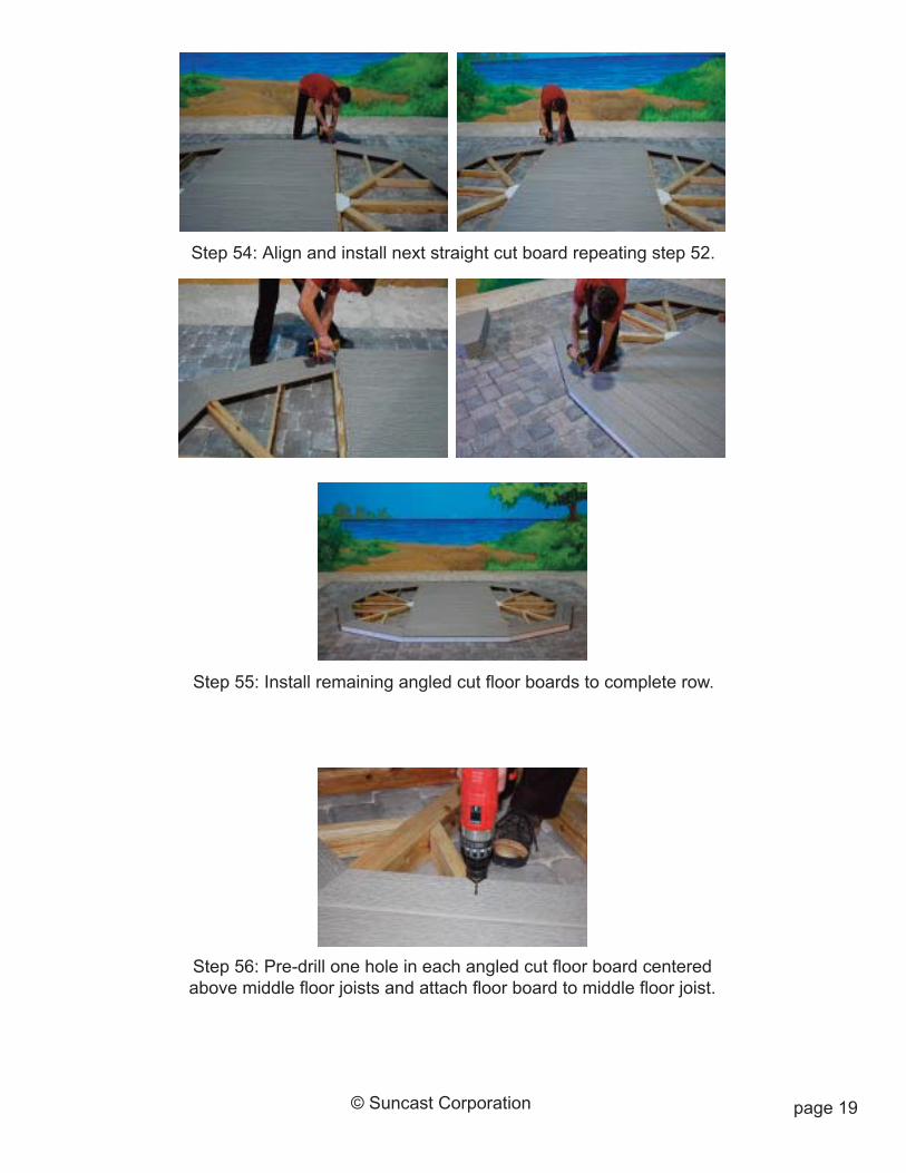
Step 54: Align and install next straight cut board repeating step 52.
Step 55: Install remaining angled cut floor boards to complete row.
Step 56: Pre-drill one hole in each angled cut floor board centeredabove middle floor joists and attach floor board to middle floor joist.
page 20© Suncast Corporation
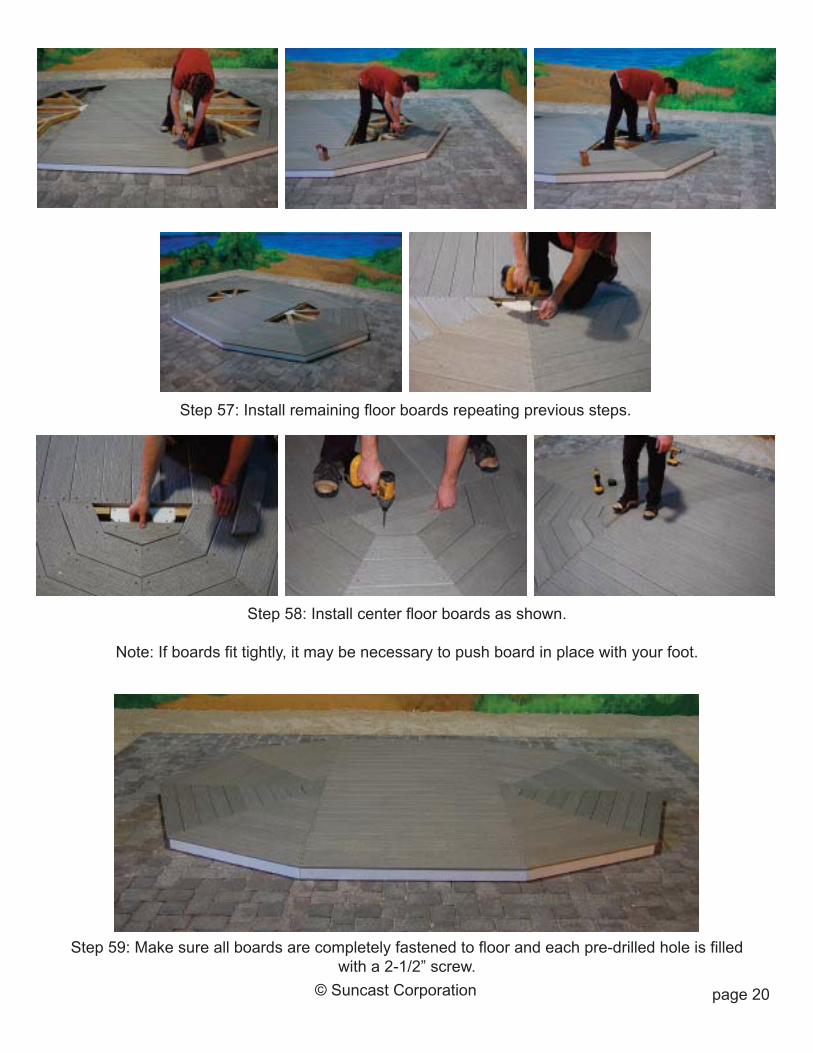
Step 57: Install remaining floor boards repeating previous steps.
Step 59: Make sure all boards are completely fastened to floor and each pre-drilled hole is filledwith a 2-1/2” screw.
Step 58: Install center floor boards as shown.
Note: If boards fit tightly, it may be necessary to push board in place with your foot.
page 21© Suncast Corporation
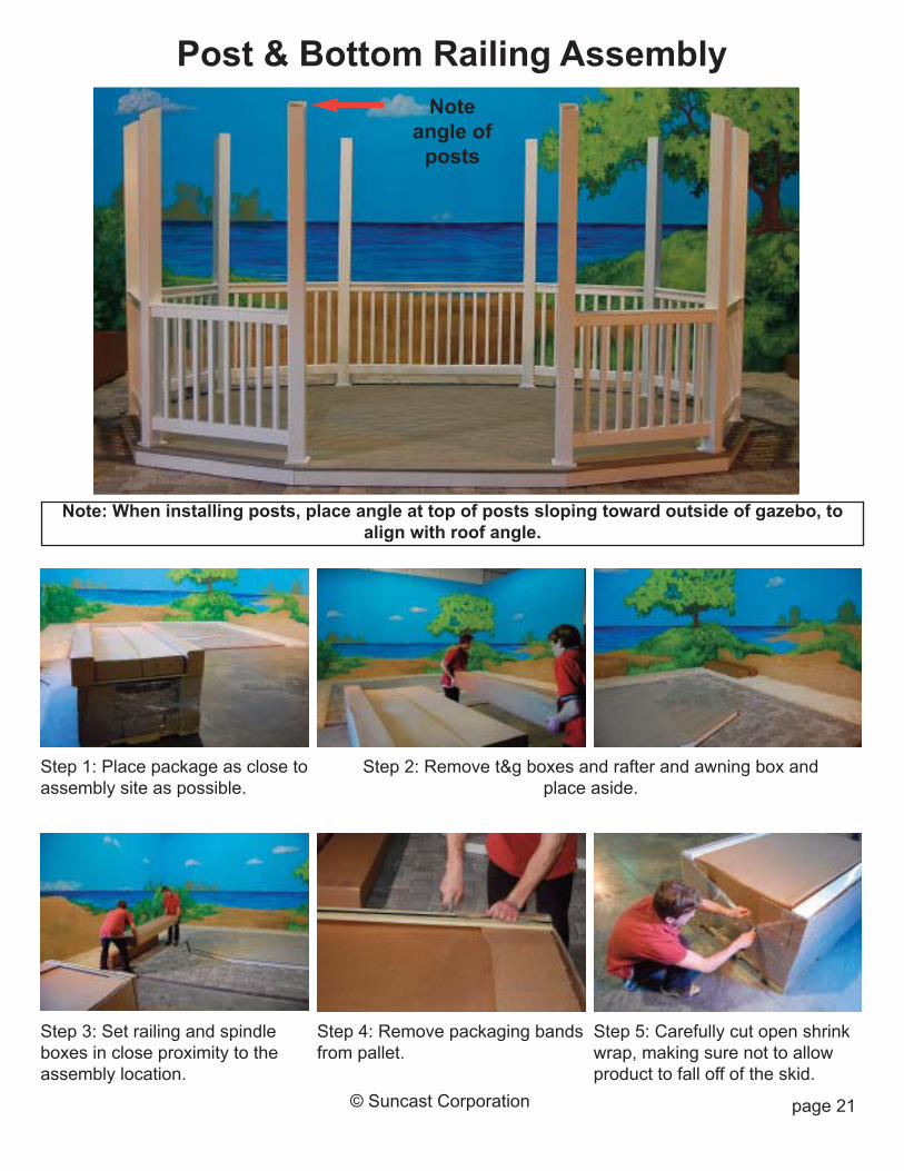
Step 1: Place package as close toassembly site as possible.
Step 4: Remove packaging bandsfrom pallet.
Step 3: Set railing and spindleboxes in close proximity to theassembly location.
Step 5: Carefully cut open shrinkwrap, making sure not to allowproduct to fall off of the skid.
Post & Bottom Railing Assembly
Note: When installing posts, place angle at top of posts sloping toward outside of gazebo, toalign with roof angle.
Noteangle ofposts
Step 2: Remove t&g boxes and rafter and awning box andplace aside.
page 22
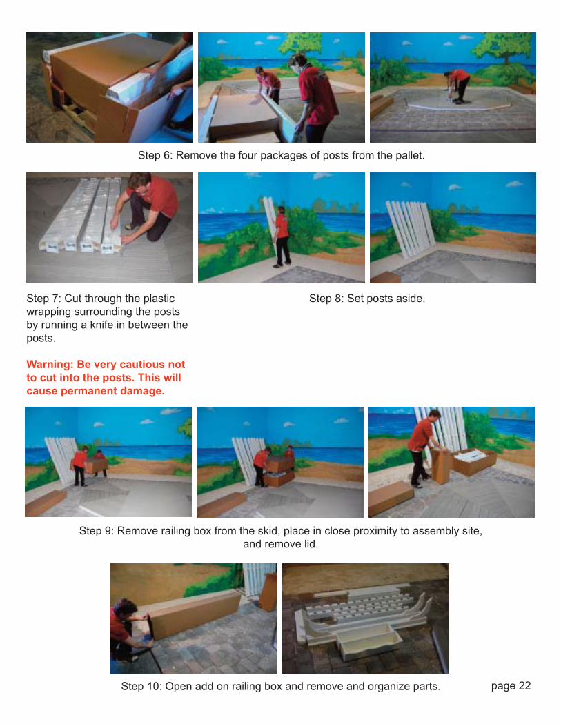
Step 8: Set posts aside.Step 7: Cut through the plasticwrapping surrounding the postsby running a knife in between theposts.
Warning: Be very cautious notto cut into the posts. This willcause permanent damage.
Step 6: Remove the four packages of posts from the pallet.
Step 9: Remove railing box from the skid, place in close proximity to assembly site,and remove lid.
Step 10: Open add on railing box and remove and organize parts.
page 23© Suncast Corporation
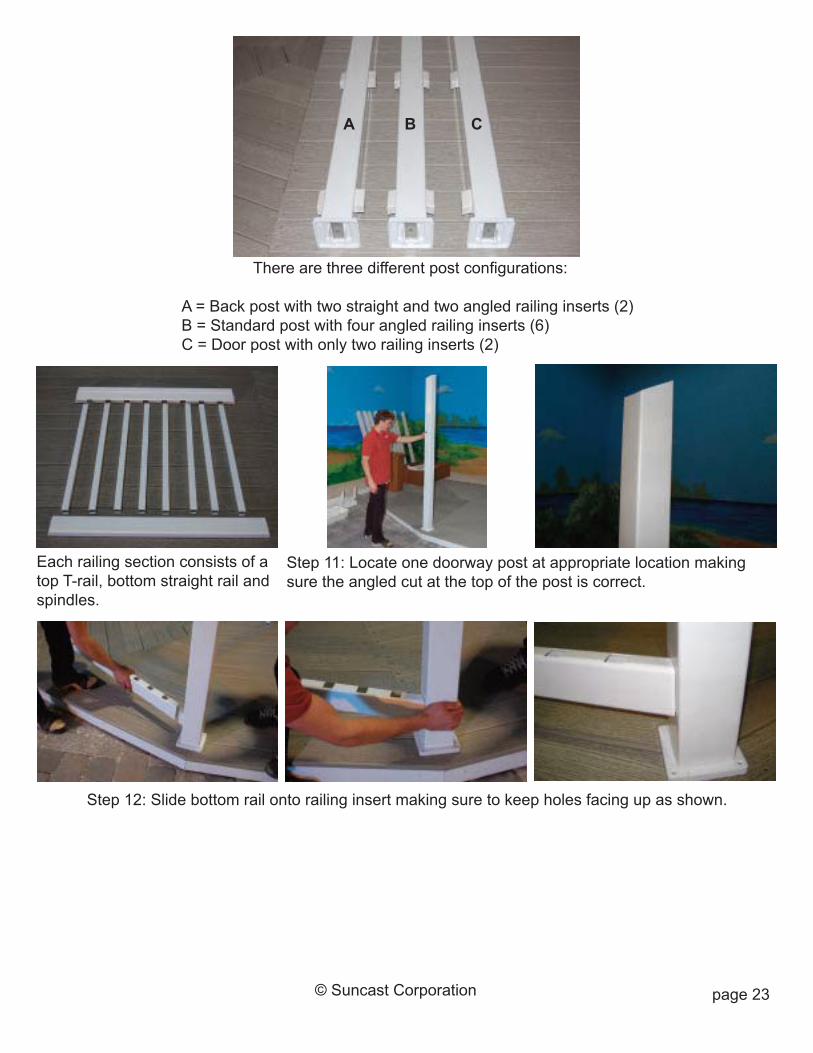
Each railing section consists of atop T-rail, bottom straight rail andspindles.
There are three different post configurations:
A = Back post with two straight and two angled railing inserts (2)B = Standard post with four angled railing inserts (6)C = Door post with only two railing inserts (2)
Step 12: Slide bottom rail onto railing insert making sure to keep holes facing up as shown.
A B C
Step 11: Locate one doorway post at appropriate location makingsure the angled cut at the top of the post is correct.
page 24© Suncast Corporation
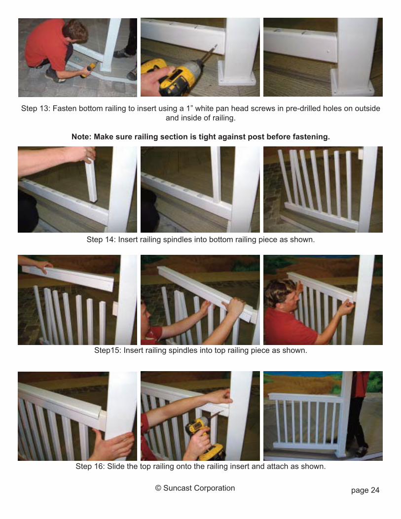
Step15: Insert railing spindles into top railing piece as shown.
Step 13: Fasten bottom railing to insert using a 1” white pan head screws in pre-drilled holes on outsideand inside of railing.
Note: Make sure railing section is tight against post before fastening.
Step 14: Insert railing spindles into bottom railing piece as shown.
Step 16: Slide the top railing onto the railing insert and attach as shown.
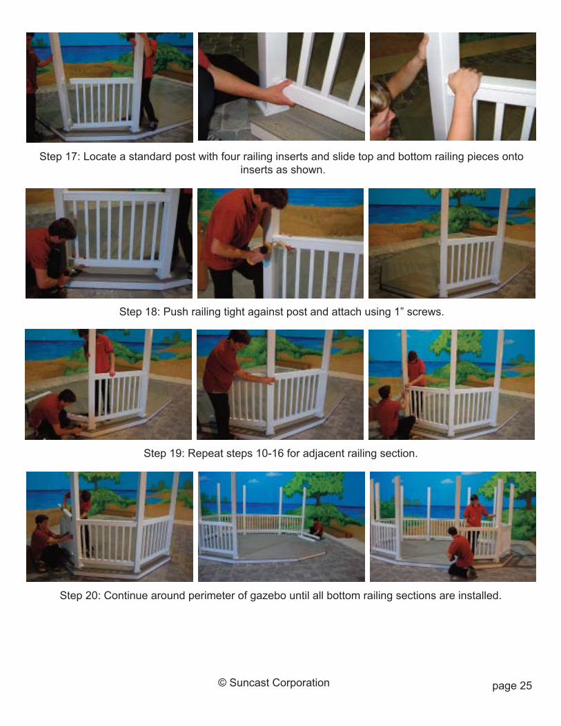
Step 17: Locate a standard post with four railing inserts and slide top and bottom railing pieces ontoinserts as shown.
Step 18: Push railing tight against post and attach using 1” screws.
Step 19: Repeat steps 10-16 for adjacent railing section.
page 25© Suncast Corporation
Step 20: Continue around perimeter of gazebo until all bottom railing sections are installed.
page 26© Suncast Corporation
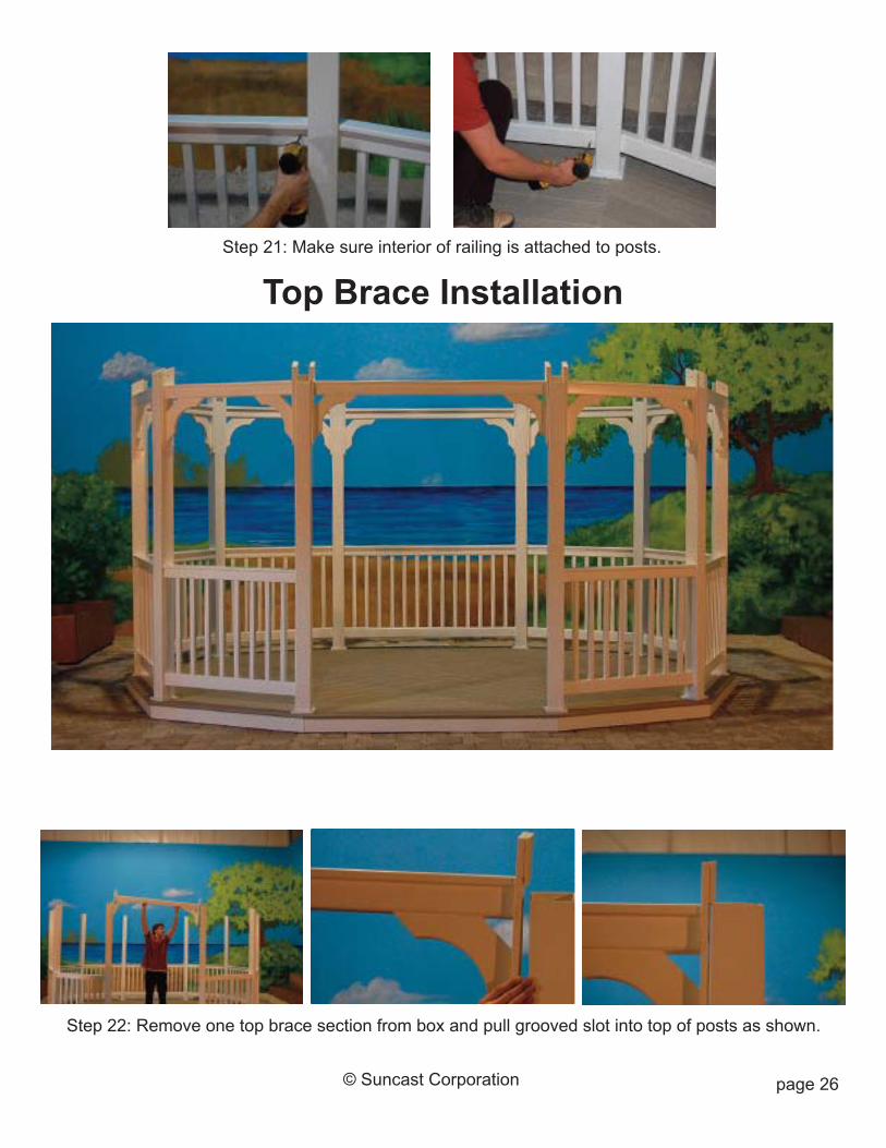
Step 21: Make sure interior of railing is attached to posts.
Top Brace Installation
Step 22: Remove one top brace section from box and pull grooved slot into top of posts as shown.

page 27© Suncast Corporation
Step 24: Pull brace section down tight against top of post, align centered on post, and attach using 2-1/2”white screws through pre-drilled holes.
Step 23: Continue installing brace sections around perimeter of gazebo repeating step 22.
Step 25: Continue around perimeter of gazebo until all brace sections are fastened to posts.
page 28© Suncast Corporation
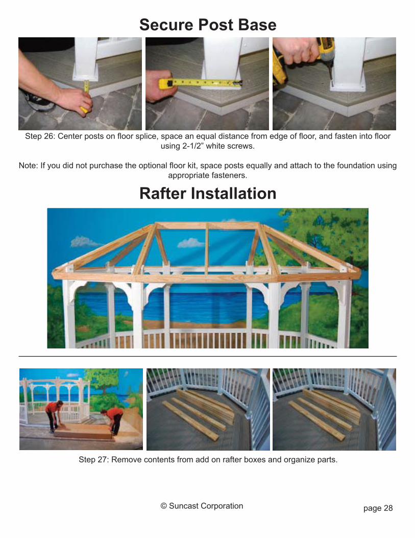
Step 26: Center posts on floor splice, space an equal distance from edge of floor, and fasten into floorusing 2-1/2” white screws.
Note: If you did not purchase the optional floor kit, space posts equally and attach to the foundation usingappropriate fasteners.
Secure Post Base
Rafter Installation
Step 27: Remove contents from add on rafter boxes and organize parts.
page 29© Suncast Corporation
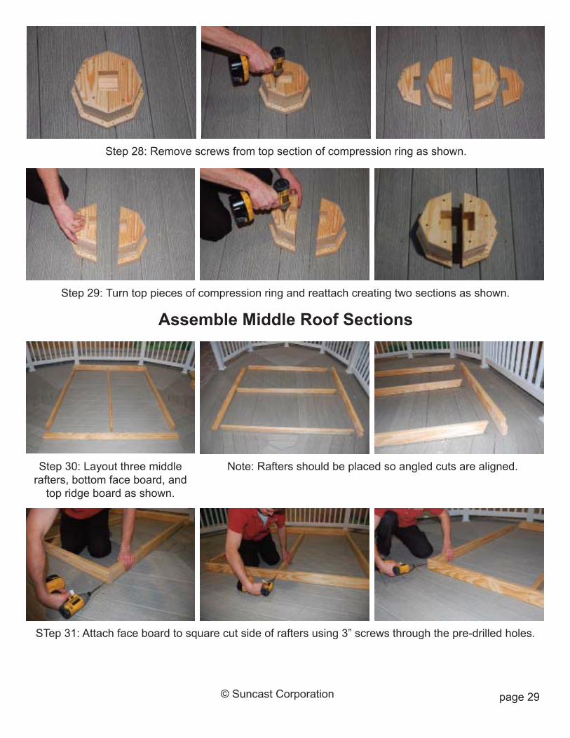
Step 30: Layout three middlerafters, bottom face board, andtop ridge board as shown.
Step 28: Remove screws from top section of compression ring as shown.
Step 29: Turn top pieces of compression ring and reattach creating two sections as shown.
Assemble Middle Roof Sections
Note: Rafters should be placed so angled cuts are aligned.
STep 31: Attach face board to square cut side of rafters using 3” screws through the pre-drilled holes.
page 30© Suncast Corporation
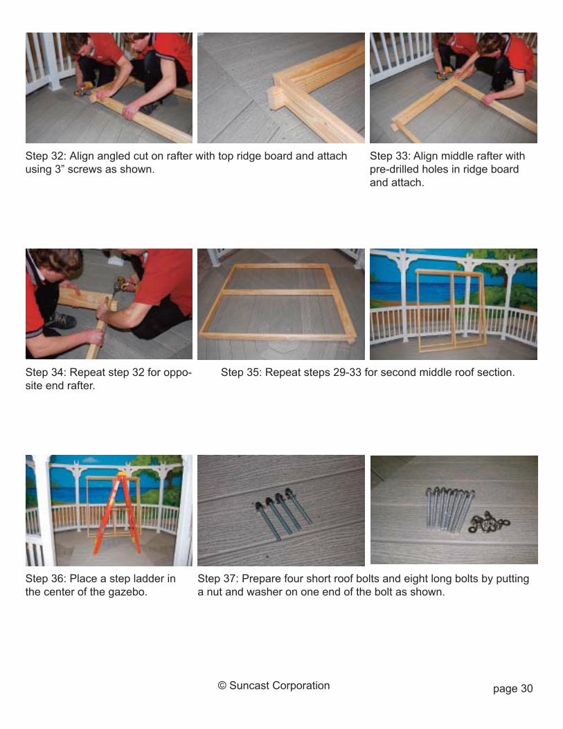
Step 32: Align angled cut on rafter with top ridge board and attachusing 3” screws as shown.
Step 33: Align middle rafter withpre-drilled holes in ridge boardand attach.
Step 34: Repeat step 32 for oppo-site end rafter.
Step 37: Prepare four short roof bolts and eight long bolts by puttinga nut and washer on one end of the bolt as shown.
Step 36: Place a step ladder inthe center of the gazebo.
Step 35: Repeat steps 29-33 for second middle roof section.
page 31© Suncast Corporation
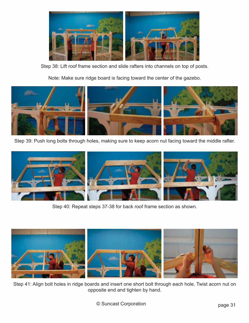
Step 41: Align bolt holes in ridge boards and insert one short bolt through each hole. Twist acorn nut onopposite end and tighten by hand.
Step 38: Lift roof frame section and slide rafters into channels on top of posts.
Note: Make sure ridge board is facing toward the center of the gazebo.
Step 39: Push long bolts through holes, making sure to keep acorn nut facing toward the middle rafter.
Step 40: Repeat steps 37-38 for back roof frame section as shown.
page 32© Suncast Corporation
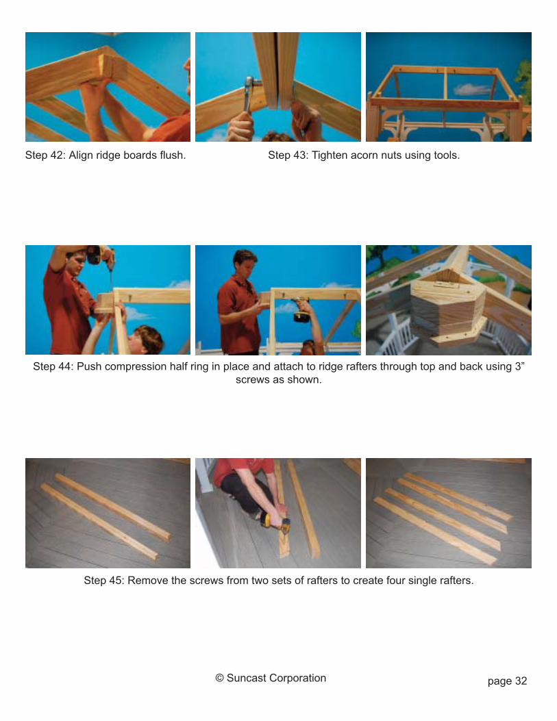
Step 43: Tighten acorn nuts using tools.Step 42: Align ridge boards flush.
Step 44: Push compression half ring in place and attach to ridge rafters through top and back using 3”screws as shown.
Step 45: Remove the screws from two sets of rafters to create four single rafters.
page 33© Suncast Corporation
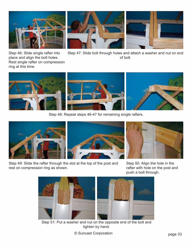
Step 46: Slide single rafter intoplace and align the bolt holes.Rest single rafter on compressionring at this time.
Step 47: Slide bolt through holes and attach a washer and nut on endof bolt.
Step 48: Repeat steps 46-47 for remaining single rafters.
Step 51: Put a washer and nut on the opposite end of the bolt andtighten by hand.
Step 49: Slide the rafter through the slot at the top of the post andrest on compression ring as shown.
Step 50: Align the hole in therafter with hole on the post andpush a bolt through.

page 34© Suncast Corporation
Step 54: Begin with the board ad-jacent to the door opening.
Step 53: Insert four 2-1/2” screwsin the pre-drilled holes in eachband board.
Step 55: Align left side of bandboard with top of rafter and at thecenter of the rafter splice and at-tach to rafters.
Step 52: Install five remaining double rafters repeating steps 49-51.
Roof Band Board Installation
Step 56: Pull band board tightagainst band board of middle roofsection.
Step 57: Attach band board to single rafter, making sure to keep alledges aligned flush.

page 35© Suncast Corporation
Step 59: Continue installing band boards, always installing the left side first and then aligning cornersat right side as shown.
Step 58: Attach single rafter to middle roof section using four 2-1/2” screws spaced evenly apart.
Step 61: Make sure all single rafters are attached tomiddle roof section.
Step 60: Install remaining band boards around entire perimeter of gazebo.
page 36© Suncast Corporation
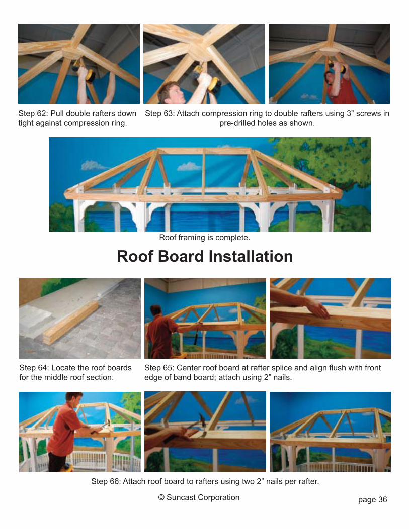
Step 62: Pull double rafters downtight against compression ring.
Step 63: Attach compression ring to double rafters using 3” screws inpre-drilled holes as shown.
Roof framing is complete.
Roof Board Installation
Step 64: Locate the roof boardsfor the middle roof section.
Step 65: Center roof board at rafter splice and align flush with frontedge of band board; attach using 2” nails.
Step 66: Attach roof board to rafters using two 2” nails per rafter.
page 37© Suncast Corporation
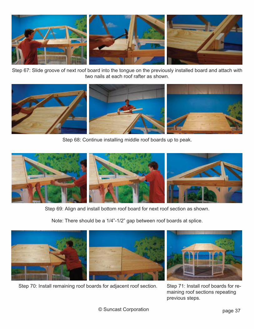
Step 67: Slide groove of next roof board into the tongue on the previously installed board and attach withtwo nails at each roof rafter as shown.
Step 68: Continue installing middle roof boards up to peak.
Step 70: Install remaining roof boards for adjacent roof section. Step 71: Install roof boards for re-maining roof sections repeatingprevious steps.
Step 69: Align and install bottom roof board for next roof section as shown.
Note: There should be a 1/4”-1/2” gap between roof boards at splice.
page 38© Suncast Corporation
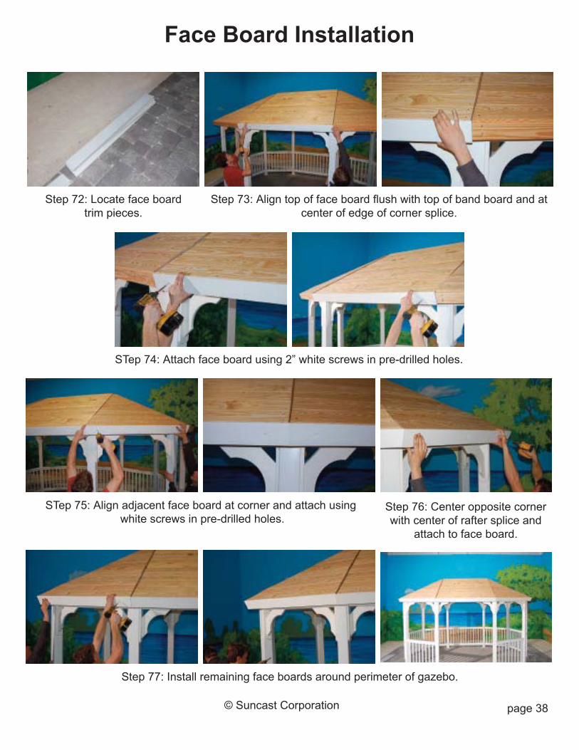
Step 72: Locate face boardtrim pieces.
STep 74: Attach face board using 2” white screws in pre-drilled holes.
Face Board Installation
Step 73: Align top of face board flush with top of band board and atcenter of edge of corner splice.
STep 75: Align adjacent face board at corner and attach usingwhite screws in pre-drilled holes.
Step 76: Center opposite cornerwith center of rafter splice and
attach to face board.
Step 77: Install remaining face boards around perimeter of gazebo.
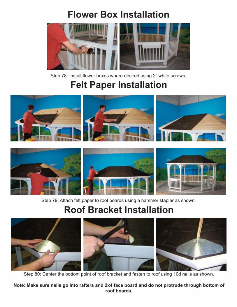
Step 78: Install flower boxes where desired using 2” white screws.
Flower Box Installation
Felt Paper Installation
Step 79: Attach felt paper to roof boards using a hammer stapler as shown.
Step 80: Center the bottom point of roof bracket and fasten to roof using 10d nails as shown.
Note: Make sure nails go into rafters and 2x4 face board and do not protrude through bottom ofroof boards.
Roof Bracket Installation