
Summary of the Effects of Engine Throttle Response on ...
30
NASA Technical Memorandum 4465 i -Z=-2W - Summary of the Effects of Engine Throttle Response on Airplane Formation-Flying lities " C. - : .;-:;- - Z. Z_ Kevin R. Walsh MARt H t .... (',_ A-! ,'-44_5) SUY -_A_Y 'J_ T_" -F.-CTS _F F_INE TH_3TTLE q_zSPONSE -].. AIRPL_'_E FqR,_ATION-FLYI_G L_UAL ITILS (_ASA) 2o p ..J/L.; Ci_ <Z :_ ] "_ , / HI/O8 ! 7_ l i N Uncl as _--" 0153700 N
Transcript of Summary of the Effects of Engine Throttle Response on ...

NASA Technical Memorandum 4465
i -Z=-2W-
Summary of the Effects of Engine
Throttle Response on Airplane
Formation-Flying lities
" C. -
: .;-:;-- Z. Z_
Kevin R. Walsh
MARt H t ....
(',_ A-! ,'-44_5) SUY -_A_Y 'J_ T_"
-F.-CTS _F F_INE TH_3TTLE q_zSPONSE
-].. AIRPL_'_E FqR,_ATION-FLYI_G
L_UAL ITILS (_ASA) 2o p
..J/L.; Ci_ <Z:_
] " _ ,/
HI/O8
!
7_
l
i
NUncl as _--"
0153700 N


NASA Technical Memorandum 4465
Summary of the Effects of Engine
Throttle Response on Airplane
Formation-Flying Qualities
Kevin R. Walsh
Dryden Flight Research Facility
Edwards, California
National Aeronautics andSpace Administration
Office of Management
Scientific and Technical
Information Program
1993


SUMMARY OF THE EFFECTS OF ENGINE THROTTLE
RESPONSE ON AIRPLANE FORMATION-FLYING QUALITIES
Kevin R. Walsh*
NASA Dryden Flight Research FacilityP.O. Box 273
Edwards, California 93523-0273
Abstract
A flight evaluation was conducted to determine the
effect of engine throttle response characteristics on pre-cision formation-flying qualities. A variable electronic
throttle control system was developed and flight-tested
on a TF-104G airplane with a J79-11B engine at the
NASA Dryden Flight Research Facility. This airplane
was chosen because of its known, very favorable thrust
response characteristics. Ten research flights were
flown to evaluate the effects of throttle gain, time delay,and fuel control rate limiting on engine handling quali-
ties during a demanding precision wing formation task.
Handling quality effects of lag filters and lead compen-
sation time delays were also evaluated. The Cooper
and Harper Pilot Rating Scale was used to assign lev-
els of handling quality. Data from pilot ratings and
comments indicate that throttle control system timedelays and rate limits cause significant degradations in
handling qualities. Threshold values for satisfactory
(level 1) and adequate (level 2) handling qualities of
these key variables are presented. These results mayprovide engine manufacturers with guidelines to assure
satisfactory handling qualities in future engine designs.
Introduction
The ability to conduct such precise flying tasks as
close-formation flight or aerial refueling is strongly af-fected by the engine throttle response, that is, thrust
response caused by throttle changes. With the ad-
vent of digital engine control systems, control soft-
ware has become commonly used to modify engine re-
sponse characteristics) The engine throttle response
may be degraded if such modifications are improperly
"Aerospace Engineer.
Copyright (_)1992 by the American Institute of Aeronautics
and Astronautics, Inc. No copyright is asserted in the UnitedStates under Title 17, U.S. Code. The U.S. Government has
a royalty-free license to exercise all rights under the copy-
right claimed herein for Governmental purposes. All other
rights are reserved by the copyright owner.
validated. No criteria for defining good or bad enginethrottle response characteristics currently exist.
In the past 10 years, engine throttle response prob-
lems have been encountered in several airplanes, for ex-
ample, the F-15 (McDonnell Douglas Corporation, St.
Louis, Missouri) with the developmental F100 enginemodel derivative (Pratt & Whitney, West Palm Beach,
Florida), _ AV-8B (McDonnell Douglas Corporation,
St. Louis, Missouri), 3 and F-18 (McDonnell Douglas
Corporation, St. Louis, Missouri, and Northrop Cor-
poration, Hawthorne, California). Problems in these
examples ranged from excessive initial time delay or
lag in the F-15 and AV-SB airplanes to high throttlesensitivity in the initial F-18 installation. Such exam-
ples illustrate the need for handling quality guidelines
or design specifications for advanced engine control sys-tems. These engine design specifications are analogousto those developed over the last two decades for ad-
vanced flight control systems. As a result, data are
required to develop handling qualities criteria to quan-
tify the effects of thrust response dynamics on a pilot's
ability to complete precision flight control tasks.
A brief flight research program was conducted at
the NASA Dryden Flight Research Facility (DFRF)to investigate the effects of varying engine throttle re-
sponse on airplane handling qualities. An electronic
variable-throttle response system was developed and
installed on a two-seat TF-104G airplane (Lockheed
Corporation, Burbank, California). This airplane was
an ideal choice because its J79-11B engine (GeneralElectric, Lynn, Massachusetts) responds to throttle
changes extremely quickly. The variable-response elec-
tronic throttle enabled the pilot to evaluate throttle
system degradations and resulting effects on enginehandling qualities.
This program provides initial data for developing
handling qualities criteria and design guidelines for at-
taining satisfactory (level 1) throttle response of high-performance airplane engines. Data were obtained at
one flight condition: the airspeed was 300 kn, and the

altitudewas15,000ft. Thisflightconditionrepresentsa formation-flyingtask.
Thispapersummarizestheresultsof theflight re-searchprogramanddescribesthevariable-throttlere-sponsesystemasinstalledin the TF-104Gairplane.Timehistorydatafortherepresentativepilot evalua-tionsandacompilationofpilotcommentswithrespectto the timehistorydataarepresented.Thesedatashowthe differencesbetweensatisfactory,adequate,andinadequate(level1,2, and3) handlingqualitieson theCooperandHarperPilotRatingScale.4 Datashowingtimedelayandrate limit thresholdsfor thedifferentlevelsofhandlingqualitiesarealsopresented.Additionaldatashowthe effectsof a first-orderlagfilterandofa lead-lagfilter incombinationwithaddi-tionaltimedelayonhandlingqualities.
TheworkofGeorgeE.CooperandRobertP.ltarper,Jr., is gratefullyacknowledged.4 Thisworkwasin-strumentalindevelopingthisenginehandlingqualitiesflighttestprogram.
Nomenclature
AX aircraft longitudinal acceleration, 9
9 acceleration of gravity, ft/sec 2
HQR handling quality rating
L/L lead-lag
LVDT linear variable-differential transformer
MTE mission task element
N1 compressor speed, rpm
PCM pulse code modulation
PIO pilot-induced oscillation
PLA power lever angle, deg
PLACMD power lever angle command, deg
PLAFH power lever angle position feedback, deg
rpm revolutions per minute
RVDT rotary variable-differential transtbrmer
TCU throttle control unit
AT' change in time delay, msee
6x throttle position limit commanded bythrottle control unit, deg
re L/L denominator time constant
rn L/L numerator time constant
w,_ second-order lag natural frequency
¢ second-order lag damping ratio
Airplane and Engine Description
The test airplane was a TF-104G: a high-
performance, two-place, trainer-fighter-interceptor air-
plane with a maximum Maeh number of 2.0.
Figure 1 shows the TF-104G airplane. Notable fea-
tures include the extremely thin ttight surfaces, the
short and straight wings with 10° anhedral, and a con-trollable horizontal stabilizer mounted at the top of
the vertical stabilizer. The wings have leading- and
trailing-edge flaps and a boundary-layer control sys-
tem used with the trailing-edge flaps to reduce landing
speeds.
EC 80-12366
Fig. 1. The TF-104G airplane.
The J 79-11B is an axial-flow, high-pressure-ratio tur-
bojet engine with variable-inlet guide vanes, variable-stator vanes, and single-rotor compressor. This engine
has a cannular combustor, a three-stage turbine, and a
fully modulating afterburner with a variable-area con-
verging and diverging exhaust nozzle.
Variable-Response Throttle System
Description
The electronic variable-response throttle control sys-
tem was developed by Calspan (Buffalo, New York)
specifically for the DFRF TF-104G airplane. Neal and
Sengupta described the implementation and operationof the throttle control system. 5 The throttle in the
forward cockpit was modified to command the exper-imental system. Figure 2 shows the main components
of the system. These components consist of an elec-
tronic throttle control unit (TCU), integrated servomo-
tor and clutch assembly, and position sensors. A cable
linkage connected the servomotor with the engine fuelcontroller. The throttle in the aft cockpit remained in
the production configuration and served as the safety
backup system.
Figure 3 shows a simplified block diagram of the
modified propulsion control system. Additional throt-
tle system dynamics were generated by the TCU and
ORIGINAL PAGE
BLACK AND WHITE PHOTe(3,RAPI-I

Servomotor
Throttle
control
Rotary variable-
differential transformer Linear variable-_diff'erential transforme_'_ '_: ..........
920645
Fig. 2. Electronic throttle system hardware.
Pilot_
i
ETCU
variables
,)PLACMD
r
Fig. 3. Modified propulsion control system.
the servomotor. For example,, the power lever angle
commanded (t-'LACMD) by the pilot is modified by
the TCU to command the servomotor. The resulting
change in the power lew.'r angle (f)LA) caused by the
servomotor is the input to the fuel controller. This an-
gle provides PLA position feedback (PLAFI3) to the
electronic control system. Measurements of compres-
sor speed (N1) and aircraft longitudinal acceleration
(AX) are also represented. Throttle gain or sensitiv-
ity, 9/deg; transport time delay, sec; and rate limiting,
deg/sec were the primary variables for the experiment.
The secondary variables included first-order lag filter
time constants and lead-lag time constants.
Figure ,1 shows a functional block diagram of the
electronic throttle control system. The descriptors out-
side the polygon represent, the mechanical system, and
the e.lcctronic system is shown inside the polygon.
Mechanical System
In the production TF-104C, airphme, a conventional
cable and pulley system connects the forward arm aft
throttles to the engine fuel control. The two throttle
handles are linked so that, whe.n one throttle handh'.
is moved, the other tracks its position. As a re, suit,
the position of the forward and aft throttles match at
all time.s.
To incorporate the electronic throttle system, the
forward or evaluation throttle was disconnected by re-
moving the throttle linkage to the fuel control cables.
A rotary variable-differential trarisf(_rmer (I{VI)T) was
conrw.cted to the throttle handle through gears and in-
stalled in the throttle housing to sense forward throb
tie position, l)isconnecling the forward throttle from
the cable system eliminated the inherent friction on the
throttle handle; therefore, an ad,justabh.' friction device
was installed in the housing to maintain throttle feel.
This device, a small phenolic block and bracket, created
drag against the throttle-handle axle. The device was
intended to be adjustable to any friction level; however,
the throttle stick force was adjustable to a maximum
of 2 lb or approximately one'-half of the normal stick
force for the production throtth:.
EILACK AND WHITE PH_OT_9(_PH

/---
Forwardcockpitthrottlecommand
(electrical)
Aft cockpitthrottlecommand
(mechanical)
_I Vadeble-
ThrottleControlUnit (locatedin aft cockpit)
-I commandgain +'-+,_:
__ StepInput _
_ ( ,CUtest--" commend
Verlable.lrequency
sinewavegenerator Slnueoldal
input
L Variable- Variable-command --_ command
I position rotei limit limitI
Commandsignalfiltem(lead-lag,second-orderlag, --
timedelay, or cascadecombinations)
Linear mode
(nofilters)
RVDTpositionsensor
_R Servomotor L__
ddve amplifiersI
ate feedback
oo
Servomotor! (Cablelinkage).-b /- Double
assembly I / drive pulleyTachometer!
i tJ ''0on*ro'lF---I valve lLVDT
positionsensor
Positionfeedback
Originalcable linkage1 920191
Fig. 4. The throttle
A servomotor, clutch, and cable assembly was in-
stalled in the engine bay to position the filel controller.
A linear variable-differential transformer (LVDT) was
used to sense PLA at the fuel controller.
The TCU was installed in the left-hand console of
the aft cockpit and provided the desired throttle re-
sponse variations for the experiment. The backseat
pilot could disengage or override the electronic throt-
tle control system at any time. The mechanical con-
trol system was always functional from the aft cock-
pit. Since the aft cockpit throttle was mechanically
linked to the fuel control valve, the rear throttle po-
sition tracked the throttle commands. The front seat
pilot had no way to control the engine if the TCU were
disengaged.
Electronic System
The block diagram inside the shaded polygon of
Fig. 4 shows the electronics of the throttle control sys-
tem. The RVDT generated an electrical signal which
was amplified by a gain factor in the TCU. The TCU
checked the amplified signal against position (ampli-
tude) and rate limits. This signal was compared with
the actual throttle position at the fuel control valve
which was measured by the INDT. The difference be-
tween the RVDT command and the LVDT feedback
signals was an error signal used to advance or retard
the servomotor position. A tachometer on the servo-
motor assembly provided a rate feedback to the TCU.
The damping characteristics of the electronic control
control system.
system were optimized by adjusting the rate feedback
gain.
Figure 5 shows the TCU panel which the aft pi-
lot used to activate the system, select the operating
mode, set the system variables, and enter test signals.
The TCU inserted time delays, rate limits, lead-lag
time constants, first- and second-order lags, and po-
sition limits into the command path. These variables
acted directly on the pilot throttle commands. A ro-
tary switch on the TCU panel was used to select the
desired test variables. Thumbwheel switches on the
control panel were used to set the value of the test vari-
ables. The variables could be tested individually with-
out altering other variables. They could also be cas-
caded, such as testing a time delay followed by a lead-
lag filter. Positive and negative rate limits could be ad-
justed independently to simulate an engine that would
increase revolutions per minute (rpm) at a different
rate than it would decrease rpm. The output signal of
the circuit selected was then rate and position limited.
Circuits in the TCU could selectively generate two
test inputs: a step signal and a sinusoidal signal. The
step input had either positive or negative polarity, and
the sinusoidal input could vary from 0.0 to 2.9 Hz. The
test inputs were used during the flight program; how-
ever, the data are not presented in this paper. Re-
fer to Ref. 5 for additional information concerning the
implementation and operation of the variable-response
electronic throttle system in the TF-104G airplane.

Red LED Indicates
servoclutch has
been powered --_
_n _d
Lead-lag
NN_ mn
Second-order lag
ND
Test frequency
Test
Thumbwheel switches
for setting control system
variable parameters
AT 5x max Command gain Idelay position I
,I /- Red LED indicateslimit
[_ [_ V power to servomotor
Ra_'e limit (Sx max) CON/] _ Yellow LED indicates0 r----Tellt--_ AT -_ //.*L/L-ZIT OSTBY .if power to TCU
Engage ISin Poa [ 2nd \ //2nd-,,IT ON J electronics
_- Sequence select switch for
choosing mode of operation
Fig. 5. The throttle control unit panel.
92O192
Instrumentation
Information from the airplane, engine, and TCUwas obtained on a pulse code modulation (PCM)
data acquisition system. The serial PCM data were
telemetered to the ground, decoded and formatted for
real-time display on cathode ray tubes and strip charts,
and recorded for postflight analysis. Instrumented pa-
rameters were measured at 200 samples/sec.
Measured values of pressure and temperature were
used to generate computed values of airspeed, altitude,
Mach number, static temperature, and standard day
temperature at altitude. These calculated parameters
were also formatted for real-time display. Tables 1 and
2 in Ref. 5 show the airplane, engine, and TCU param-eters that were measured for this experiment.
Development of Handling Qualities
Experiment
This discussion describes the development of the
electronic throttle handling qualities experiment and
is based on the work of Cooper and Harper. 4 To
achieve reliable data and comparable ratings among
the pilots, care was taken in developing the experiment
objectives, mission description, mission task elements
(MTE) 6, rating criteria, pilot assessments, and flight
test procedures.
Objectives
In general, the experiment obtained highly definitive
handling qualities data for a modified J79-11B engine
in a TF-104G airplane. According to U.S. Air Force
military specification MIL-F-8785C, the TF-104G air-
plane, being a highly maneuverable fighter and inter-ceptor, is considered a class IV aircraft. 7
Formation flying was the mission of interest for the
evaluations. The specification classifies formation fly-
ing as a category A flight phase. 7 This flight phase
requires rapid maneuvering, precision tracking, or pre-
cise flightpath control.
The primary variable for obtaining handling qualities
data was thrust control. Other typical handling quality
variables, such as airframe stability and control char-
acteristics as well as cockpit interface elements, werenot considered.
The five pilots who participated in the program were
experienced in evaluating handling qualities of class IV
airplanes. Their role was important in determining
pilot and vehicle performance during the task. Fig-ure 6 shows a modified Cooper and Harper Handling
Qualities Rating (HQR) Scale. This scale defines sat-
isfactory, adequate, and inadequate (level 1, 2, and 3)
perform ance.
Mission Description
The required operation for the formation-flying task
was to attain and maintain fore and aft position rel-
ative to the wing of the lead airplane by using visualreferences. This high gain, precise, closed-loop track-
ing task requires the pilot to devote full-attention to
airplane control and to use the throttle as the primary
control input.
5

Adequacyforselected taskor requiredoperation ) CAircraftcharacteristics "Demandson the pilotin
selectedtask or requiredoperation'
• Excellent, • Pilotcompensationnot a factorhighlydesirable for desiredperformance
Good, Pilotcompensationnot a factornegligibledeliciencies • for desiredperformance
Fair, somamildly • Minimalpilot compensationrequired_ unpleasantdeficiencies for desiredpedormance
• Minorbut annoying Desiredpedormancerequiresdeficiencies • moderatepilot compensation
Moderatelyobjectionable• Adequateperformancerequiresdeficiencies considerablepilot compensation
Veryobjectionablebut • Adequateperformancerequires_ tolerabledeficiencies extensivepilotcompensation
Adequateperformancenot attainablewith maximumMajordeficiencies • tolerablepilot compensation;controllabilitynot in question
Majordeficiencies • Considerablepilot compensationis requiredfor control
Intensepilot compensationMajordeficiencies •_.. is requiredto retain conlrol
Yea
Pilot ] Handling'_rating I quality ,,)
1
LevelI,2 satisfactor
3
withoutDeficiencies
warrantimprovement
Level2,adequate
Yes
attainablewithDeliclencies'_
7
Level3,8 inadequate
9
Yes
itcontrollable_
Yea
Pilotdecisions
Majordeliciencies • Controlwill be lostduring someportionof requiredoperation
Fig. 6. Cooper and Harper Pilot Rating Scale.
The lead airplane for the formation task was either
a T-38 (Northrop Corporation, tiawthorne, Calilbrnia)
or an F-18. Nominal flight conditions used for the test
program were an altitude of 15,000 ft above mean sea
level and an indicated airspeed of 350 kn. This flight
condition was chosen so that throttle motion was al-
ways in partial power. Only in the worst case TCU
configurations did the throttle hit the military or idle
power detents.
Mission Task Elements
Developing a well-defined MTE with handling qual-
ity performance criteria reduces the uncertainties and
extrapolation to the real-world equivalent required by
the pilot, ttaving the pilots consider the real-world
equivalent during the evaluation lends itself to some
pilot extrapolation. Such extrapolation differs for each
pilot because of variations in training, knowledge, ex-
perience, and ability to assess beyond the specific task.
The flight subphase chosen after preliminary evalua-
tions of several formation tasks was close-wing station
keeping. This subphase was intended to be represen-
tative of the precision required in similar operational
tasks, such as in air-to-air refueling or close-formation
flight under adverse instrument conditions. Without
the introduction of suitable task perturbations to chal-
lenge the pilot and the throttle response system, the
task would not provide the desired degree of handling
qualities discrimination. Close-formation flight with a
smooth leader does not, in itself, provide the necessary
discrimination; the evaluation pilot cannot separate the
optimum from the marginally acceptable cases. Note,
for example, that even large relatively ponderous ships
can fly accurate close formations during refueling tasks
at sea.
Since the emergence of full-authority electronic en-
gine control allows the designer some flexibility, the
task must allow definition of the satisfactory (level 1)
throttle response characteristics. The MTE selected,
therefore, involved precision wing station keeping
during small and unannounced step throttle changes
by the formation leader. F_rther, the evaluation pilot
6

was to maintain relative position at all costs. In short,
the task could not be abandoned when the pilot's per-
formance degraded. The initial transient of the lead
airplane did not need to be followed exactly, but the
new position was to be recaptured quickly and accu-
rately. The real-world equivalent would be an emer-
gency air-to-air refueling or formation recovery where
it is imperative to stay in position despite turbulence
or inadvertent thrust changes by the leader.
Rating Criteria
Pilot rating is a measure of the handling performance
of an airplane, that is, pilot and vehicle performance.
Cooper and Harper define performance as "the preci-
sion of control with respect to airplane movement thata pilot is able to achieve in performing a task. "4 For this
flight evaluation, the pilot ratings were applied to theMTE as previously described and were based on how
quickly and accurately the evaluation pilot acquiredand maintained formation position. The precision of
control required by the pilot to maintain formation was
an approximately 5-ft wingtip clearance in the horizon-tal plane.
Figure 7 shows an example of the precision and
performance requirements for obtaining adequate pi-
lot performance for the MTE. The following criteria
were applied for obtaining the HQI{:
• Satisfactory performance was +1 ft with one over-shoot allowed.
• Adequate performance was -t-3 ft with two over-shoots allowed.
Another important consideration for determining
HQR was pilot workload. Cooper and Harper define
pilot workload as "the integrated physical and mentaleffort required to perform a specified piloting task. "4
In this case, physical effort is the motions and forcesimposed on the throttle by the pilot during the MTE.
No auxiliary tasks were required during the MTE so
that only thrust control characteristics were evaluated.
Additional workload imposed by auxiliary tasks would
have interfered with the pilots' evaluation of tile thrustcontrol characteristics.
Pilot Assessments
Cooper and Harper note that the pilot rating is a
"shorthand representation of the handling qualities ofan airplane in the performance of a defined mission and
task. ''4 The evaluation pilot continuously considered
the rating decision process to obtain the pilot rating
during the MTE. This process involves a series of di-
chotomous decisions based on the adjective descriptors
of the pilot rating scale (Fig. 6).
Pilot ratings of one-half (for example, Pl{ 4.5) indi-
cate an indecision or reluctance to assign either of the
adjacent ratings to describe the throttle configuration.
Ratings of 3.5, 6.5, and 9.5 are generally not used be-
cause they represent important boundary conditions.
The boundary conditions are based on yes or no de-cisions to obtain satisfactory, adequate, or inadequate
(level 1, 2, or 3) handling qualities.
Pilot comments were recorded during the evaluations
to avoid having the IIQR represent the entire quali-tative assessment. Pilot comments are one means of
identifying good or deficient qualities of a configura-
tion. During an evaluation, the pilots reported what
they saw and felt and described their difficulties in com-
pleting the MTE. Such comments were in response to
a questionnaire developed for the MTE. All evaluation
pilots participated in preparing the questionnaire. This
questionnaire helped ensure thal important or suspectaspects were considered, the reason for the assigned
rating was given, the tradeoffs that the pilot must con-
tend with were understood, and any supplementary
comments that help describe the pilots' evaluation of
the configuration were provided.
Flight Test Procedures
The backseat pilot acted as the test conductor and
safety pilot for the research flights. Throttle config-urations were defined for evaluation according to the
mission plan before each test flight. These configura-
tions were written on flight cards for the backseat pilot
to use in selecting the TCU settings. This pilot could
disengage the variable-throttle response system at anytime and use the unmodified rear cockpit throttle. In
an emergency, this pilot could also overpower the throt-
tle system servomotor to command the desired throttle
inputs.
The evaluation pilots were unaware of the TCU con-
figuration during the MTE evaluations. This method-
ology was used to avoid pilot preconceptions of what
effect such configurations as throttle time delay would
have on airplane handling qualities.
Each throttle configuration was evaluated in two
stages. The set up of each test configuration was madewith significant distance between the test and lead air-
planes. After entering the test configuration, the evalu-
ation pilot maneuvered into a close-formation position
with the lead airplane. The pilot evaluated the throttle
control system during the join-up and formation phasesof the maneuver until satisfied that a valid llQl{ could
be made. Then upon command from the evaluation
pilot, the lead airplane began a series of small, random
throttle excursions called throttle jinks. These throt-
tle jinks increased or decreased the separation distanceand the rate of separation. The evaluation pilot's tasks

Test aircraft -_
two ov3rsft_loots_ _ 5"ft clealnce
920646
Fig. 7. Precision and performance requirements for adequate pilot performance.
were to aggressively reacquire and maintain the initial
separation and to evaluate the task as previously de-scribed. This pilot provided comments pertinent to the
questionnaire during the evaluation.
The evaluation pilot briefly returned to the so-called
benchmark configuration between each MTE. Notethat the evaluation pilot knew that this was the bench-
mark configuration. This configuration was essentiallythe basic J79-11B engine (that is, the TCU in linear
mode) modified by the throttle servodynamics, opti-
mum throttle control gain, and change in throttle fric-
tion. Evaluation pilots had the option of re-flying the
task in the benchmark configuration to ensure qualitycontrol of each evaluation. Afterward, the pilots could
change the HQR, but they rarely made such changes.
Since l0 to 14 evaluations were performed during each
flight, this benchmark procedure helped the pilots to
retain a good reference standard.
Upon completion of the task, control was returned to
the backseat pilot. Then, the evaluation pilot assigned
an HQR and provided more comments regarding theperformance of the configuration.
Flight Test Results and Discussion
Five pilots flew 10 flights to evaluate the electronic
throttle control system. Two of the flights were
flown to check the variable-throttle response system
functionally, define the MTE, critique the manner in
which the task was performed, and evaluate the pilots'
assessment of the task. Only data from four of the pi-
lots are presented in this paper because the data from
the fifth pilot does not apply to the results discussed.During the flight test program, 113 data points con-
sisting of pilot ratings and comments were gathered.
The primary goals of the flight test program were
to investigate the thrust control sensitivity effects of
throttle gain, time delay, and rate limiting on airplanehandling qualities. In addition, the insertion of the
electronic throttle control system changed the baselinethrottle system dynamics. Such changes needed to be
quantified. Secondary goals were to investigate the ef-fects of first-order lag filter time constants as well as
lead-lag filter time constants. Although the primarygoals were met, insufficient data were available to draw
conclusions about the secondary goals.
Time history data are presented for the representa-
tive pilot evaluation tasks. In addition, a compilation
of pilot comments with respect to the time history datais shown. These data show the differences between sat-
isfactory, adequate, and inadequate (level 1, 2, and 3)
handling qualities (Fig. 6). Data showing time delayand rate limit thresholds for the different levels of han-
dling qualities are also presented. The modified air-
plane response with the electronic throttle control sys-
tem as well as the effects of throttle gain, time delay,
rate limiting, lag filter, and lead-lag filter on engine
handling qualities are discussed next.

Airplane ResponseWith Electronic Throttle
Control System
The dynamics of the electronic throttle control sys-
tem (Fig. 3) were estimated by applying frequency re-
sponse analysis to flight test data. Determining whatadded effect the throttle servomotor had on system re-
sponse was important. The throttle servoloop repre-
sents a feedback control system. Although its com-
ponents were known, the equivalent input and output
dynamics were best estimated from flight test data.
An estimate of the airplane acceleration response to
throttle inputs, including the servomotor, was reason-
ably modeled as a first-order lag with a pure time delay
within the frequency range of interest to the task. Thebaseline break frequency and time delay which applied
to the benchmark configuration were then estimated
as first-order break frequency = 5.7 rad/sec = 0.91 Hz,
and time delay = 65 msec. The 65-msec time delay of
the throttle system is included in the time delay stated
for the following data analysis discussions.
Throttle friction force was maintained at approxi-
mately 2 lb for the experiment. This value was some-
what light when compared with approximately 5 lb offorce for the standard TF-104G throttle system. Pilotscommented about the lack of friction in the evaluation
throttle throughout the flight test program, hut theydid not think it was a factor.
Throttle Gain Effect
The throttle gain was initially evaluated to select the
optimum gain value. The optimum throttle command
gain for this electronic throttle control system was de-termined to be 1.5. This command gain closely resem-
bled the baseline response of the standard TF-104G
airplane. This value was then used as the benchmark
configuration and in the majority of the evaluation con-
figurations. The following table shows the number of
evaluations and the average of all the HQR's for the
given command gain:
Gain setting No. of evaluations HQR1.0 5 4.60
1.5" 15 2.65
1.7 1 4.002.0 4 4.25
*This gain equates to 0.008 g/deg of throttle motionfor the nominal TF-104C, gross weight of 18,500 lb
(=t=2,500 lb variation during a flight).
Throttle Time Delay Effect
The effects of additional time delay are summarized
in Fig. 8 showing HQR plotted as a function of time
delay. The data at 65-msee time delay represent the
10
9
8
7
6
HQR5
4
3
2
10 100 2OO
° o,eve,2
Level 1
I I I t I I I
300 400 500 600 700 800 900
Time delay, msec _2o1_
Pilot
O A
DBAC<>o-_ Average for
time delay
Fig. 8. Effect of throttle control system time delay on pilot rating for command gain = 1.5 and rate limit -- =[=99
deg/sec.

benchmarkconfiguration.This65-msectimedelayac-countsfor the throttle servomotorandthe airplanewhichwaspreviouslyestimated.Ratelimit wassetfor+99 deg/sec for all time delay evaluations.
The data trend shows a steep degradation of tlQRwith added time delay. A +1 HQR band was super-
imposed on the data. Approximately 90 percent of the
data falls within this band. Significant thrust pilot-induced oscillations (PIO's) occurred during the evalu-
ation task for time delay values greater than 250 msec.Data from this experiment suggest the following time
delay thresholds:
• Level 1 time delay < t00 msec (HQR _< 3.5).
• Level 2 time delay < 300 msec (3.5 < HQR 6.5).
Several cases were evaluated where the throttle gain
was changed to determine if the handling quality ef-fects of a time delay could be minimized. No trends
could be established for the limited cases studied. Ap-
parent]y, time delay problems could not be solved bysuitable command gain changes. Note, however, that a
throttle command gain of 1.5 was chosen as optimum
with an inherent time delay of 65 msec and a hysteresisloop. All pilots commented that except for the lack of
friction, this configuration responded similarly to thestandard TF- 104G airplane.
Figure 9 shows time histories and piloting comments
representing satisfactory (level 1) handling qualities for
a time delay of 65 msec. The parameters are throttle
command, throttle feedback, compressor speed, and
.4AX,
0g
w.4
8000N1,
?000rpm
6000
80PLAFB,
deg 400
8OPLACMD,
deg 40
0
F
5 10 15 20 25 30 35 40 45 50
Time,
I
L__L ...... l 1 i i 1 l _o_ ,___l
[
L ..... I .... 1__ _t ....... 1 ........ a... l _k_ _ _ .... x .... 1
r
?i
r-
I J. 1__ _ • _ __l_ _____l _ 1 __J
0 5 10 15 20 25 30 35 40 45 50
sec
(a) Time histories of pilot A, HQR = 3.0. (b) Time histories of pilot B, HQR = 2.0.
Pilot
A
B
C
D
Fig. 9.
HQR
3.0
Comments
I guess there was no time delay. Performance was as desired. Most of thetime, I was within a foot and seldom had an overshoot.
2.0 Good response for the throttle inputs I put in. Easy to fine tune final position
with small inputs. When I follow the lead airplane's thrust changes, it takesme a cycle or two to get in phase with it. That's probably more my technique
than anything.
3.0 Very responsive. Able to track changes very well, however, there is a little
bit of delay in the initial response compared to perfection. The initial re-
sponse requires a little compensation, like a quick overdrive of the throttle
to catch the rate and move into position.
2.0 Good relationship between throttle angle and rpm change. Not much ap-
parent hysteresis. Would prefer more friction in the throttle -- I am used to
working against the friction with the standard F-104 airplane.
Level 1 handling qualities for time delay = 65 msec and rate limit = +99 deg/sec.
10
920195

longitudinal acceleration. Note the small amplitude
and low frequency of the throttle command. Pilots
commented that the throttle was very responsive and
that it was easy to control fore and aft position. In
addition, they noted a good relationship between the
throttle angle and engine rpm.
Figure 10 shows time history data representing ad-equate (level 2) handling qualities for a time delay
of 225 msec. The parameters are the same as in
Fig. 9, Note the amplitude and frequency increase of
the throttle command. Pilot A recognized the time
delay, and pilot B interpreted the configuration as
a lag. Pilot A evaluated the 225-msec configuration
twice. The first time, pilot A did not have ditficulty
compensating for the delay. The second time, pilot A
required extensive compensation to complete the task.
Pilot B reported adequate performance but only with
extensive pilot compensation. This pilot could not be
precise about the task, especially when the lead air-
plane changed thrust.
Figure 11 shows time history data for inadequate
(level 3) handling qualities for a time delay of 465 msec.The amplitude of the throttle command increased,
while the frequency decreased. Both pilots moved the
throttle around a great deal and were unsure how to
compensate for this configuration. Performance was
inadequate. Pilot A's airplane oscillated more than:/:3 ft with more than two overshoots. Pilot B moved
.4
AX, 0g
--.4
8000N1,
7000rpm
6000
80PLAFB,
deg 400
8OPLACMD,
deg 40
0
__ i . _ L .__ .... • _i i • _ L_ a -- d
___t __ t t t t * J J
i
5 10 15 20 25 30 35 40 45 50
Time,
(a) Time histories of pilot A, HQR = 6.0.
[ .__ 1 t _ i _ L • _- 1 *__ *
i
L.. I 1 t 1 _ t. l t I
0 5 10 15 20 25 30 35 40 45 50
sec
(b) Time histories of pilot B, HQR = 6.0.
Pilot
A
A
HQR
4.0
Comments
(a) A small delay occurs, but I'm not having any difficulty compensating.
Gross acquisition is great; fine tracking is not all that bad. Desired performance
achieved with moderate compensation.
6.0 (b) I think there's a time delay here, and this delay causes a great deal of pilot
compensation to do an adequate job. There may be some rate deficiencies too.
I was working just about as hard as I could and still just barely hung in there.
6,0 Seems like there's some lag there. I don't detect it so much by the vibration
and the sounds -- the audio cues that I think I use in flying formation and a feel
for power changes. Seems like I put the throttle in a position to respond, andthen a little bit later the airplane moves and seems to catch up. Then I'm
backing the throttle in the other direction. I'm not in a classic PIO, but I seem
to be just moving back and forth slowly. 1can't be precise about the task,
especially when the lead aircraft is changing thrust. I guess I can adequately
perform but only with extensive pilot compensation.
Fig. 10. Level 2 handling qualities for time delay = 225 msec and rate limit = ±99 deg/sec.
11
920196

AX,
g
N1,
rpm
PLAFB,
deg
PLACMD,
deg
.4
0
--.4
8000
7000
6000
80
40
0
80
40
i m_
I I I I I l I 1 J I
1 I I I 1 I L I____ •
I I Z L I i L _ J___J
5 10 15 20 25 30 35 40 45 50
(a) Time histories of pilot A, HQR = 7.0.
i J i i i _L_ c ___ . L --I
- t i i L__ _L _ _ J
0 5 10 15 20 25 30 35 40 45 50
Time, sec
(b) Time histories of pilot B, HQR = 10.0.
Pilot HQR
A 7.0
Comments
Working the throttle, experiencing some throtOe overshoots, but don't see
much airplane motion fore and aft. Don't understand this -- isn't what I thoughta time delay would look like. Performance was not adequate -- greater than+3 ft with more than two overshoots.
B 10.0 At first, I didn't think it was all that bad, but "after the lead aircraft started making
throttle changes, I broke loose. I'm just oscillating, moving the throttle all around.
Once I get in position, I'm not sure what's going on. Seems like a big lag --moving fore and aft on the lead airplane a lot more than I'd be comfortable with.
g_o1g7
Fig. 11. Level 3 handling qualities for time delay -- 465 msec and rate limit = +99 deg/sec.
fore and aft on the lead airplane to the point of be-
coming uncomfortable. Inability to stay with a tanker
caused pilot B to rate this configuration as a 10.0.
Throttle Rate Limiting Effect
To investigate the effect of throttle system rate limit
on engine handling qualities, the rate at which the
throttle could be commanded was progressively re-
duced from that of the benchmark configuration. Thebenchmark rate limit was +99 deg/sec, and the lowest
limit tested was +10 deg/sec. For example, throttle
position can change 10 ° in 1 sec for a step input with
a +10-deg/sec rate limit. The commanded longitudi-nal acceleration in this example would be 0.008 g/see
for the first, second at the nominal TF-104G weight of
18,500 lb and throttle gain of 1.5.
Figure 12 shows the results of the rate limit eval-
uations. The HQR is plotted as a function of throt-
tle control system rate limit. The data point at -t-99-
deg/sec rate limit is for the benchmark configuration.
Note that decreasing throttle rate limits to +45 deg/sec
produced minimal change in engine handling qual-
ities. These data indicate a sharp degradation in
handling qualities with rate limit values of less than
+40 deg/sec. The HQR's at 4-40 deg/sec ranged from
2 to 6, thereby suggesting an initial handling qualitydegradation. Significant PIO occurred for rate limits
less than +25 deg/sec. Suggested threshold rate limitvalues are as follows:
• Level 1 rate limit > -t-40 deg/sec (HQR < 3.5).
• Level 2 rate limit > +30 deg/sec (3.5 < HQR <6.5).
Figure 13 shows time history data representing ad-
equate (level 2) handling qualities for a rate limit of
-t-40 deg/sec. The parameters are the same as in Figs. 9
to 11. Note that the amplitude and frequency of thethrottle command is approximately the same as ade-
quate (level 2) handling qualities with additional time
delay (Fig. 11). Pilot A evaluated the -I-40-deg/sec con-figuration twice. The first time, pilot A did not have
12

HQR
10
9
8
7
6
5
4
3
2
10
Level 3 O AB
_ C
D
- -_- Average for
time delay
- _ Level 2
i- oLevel 1
I I l I I I I I I I10 20 30 40 50 60 70 80 90 100
Rate limit, deg/sec 92o_98
Fig. 12. Effect of throttle rate limiting on pilot ratings for throttle time delay -- 65 msec and commandgain = 1.5.
difficulty compensating for the rate limit and rated the
task as a 2.5. The second time, pilot A interpreted the
rate limit as reduced gearing (Fig. 13(a)). Moderate
pilot compensation was required to obtain desired per-
formance, so an HQR of 4.0 was given. Pilot C haddifficulty anticipating the amount of throttle motion
required when the lead airplane made power changes(Fig. 13(b)). Controllability was not in question, so an
HQR of 5.5 was given based on pilot workload. Pilot
D said that at times the engine response was pretty
decent but otherwise there was a tendency to overcon-trol (Fig. 13(c)). The final response was unpredictable;
however, the airplane was controllable with adequate
performance, so an HQR of 6.0 was given.
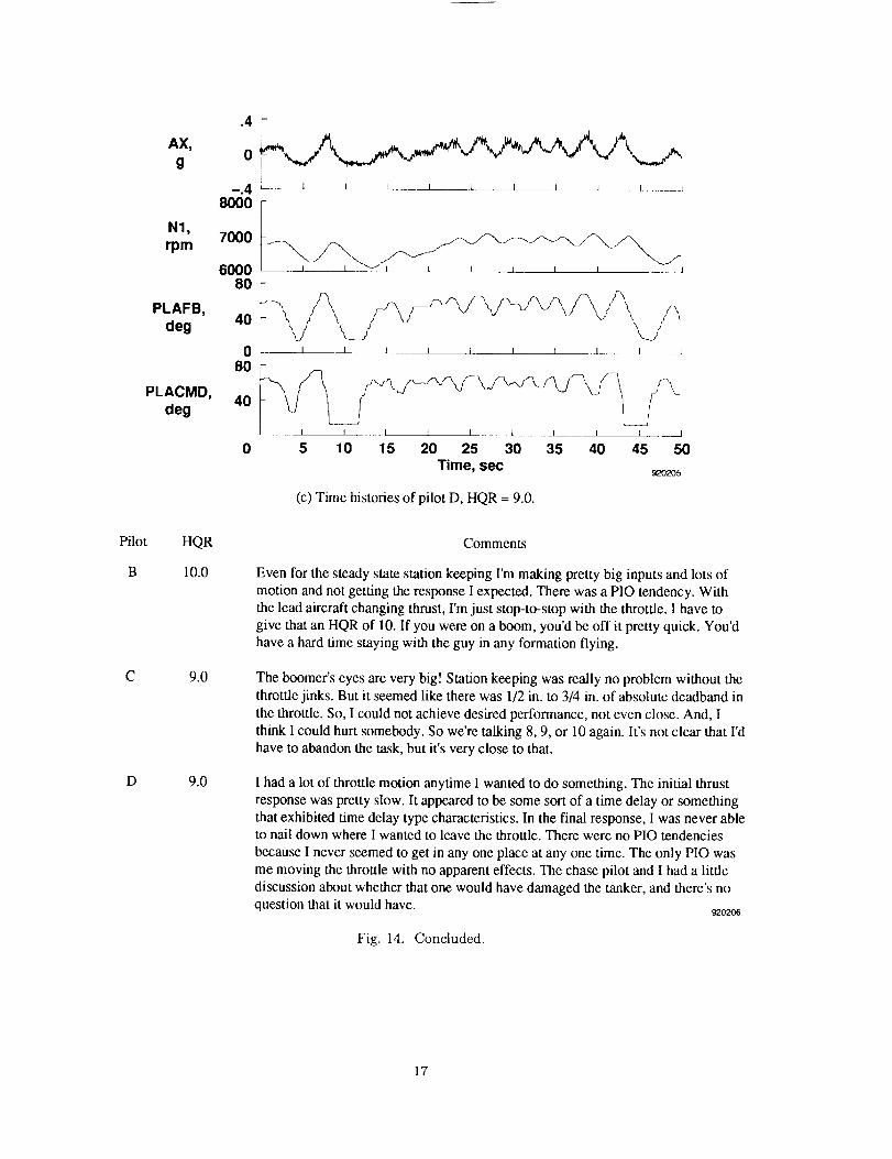
Figure 14 shows time history data of inadequate
(level 3) handling qualities for a rate limit of 20 deg/sec.
The amplitude of the throttle command increased sig-
nificantly, often from throttle stop to throttle stop
while the frequency decreased. Pilot B experienced
a PIO tendency and moved the throttle from stop to
stop in attempts to get the required engine response(Fig. 14(a)). Because a pilot would not be able to stay
on a tanker boom in such cases, an HQR of 10.0 was
given. Pilot C could not achieve adequate performance
and thought that someone could be hurt, so an tIQR of
9.0 was given (Fig. 14(b)). Pilot D commented that theinitial response was slow (Fig. 14(c)), noted that there
was some time delay, and was unable to obtain original
formation position. Pilot D was never able to position
the throttle to obtain the desired response. The PIO
was in the form of moving the throttle with no apparent
effects. There was no question that a tanker would
have been damaged, so an HQR of 9.0 was given.
Asymmetric rate limits were tested in addition to
the symmetric rate limits. The lower rate dominated
the evaluation in each case. Pilot ratings and com-
ments were comparable to those given for symmetricrate limits. For example, a 99 and -20-deg/sec rate
limit resulted in inadequate (level 3) handling qualities.
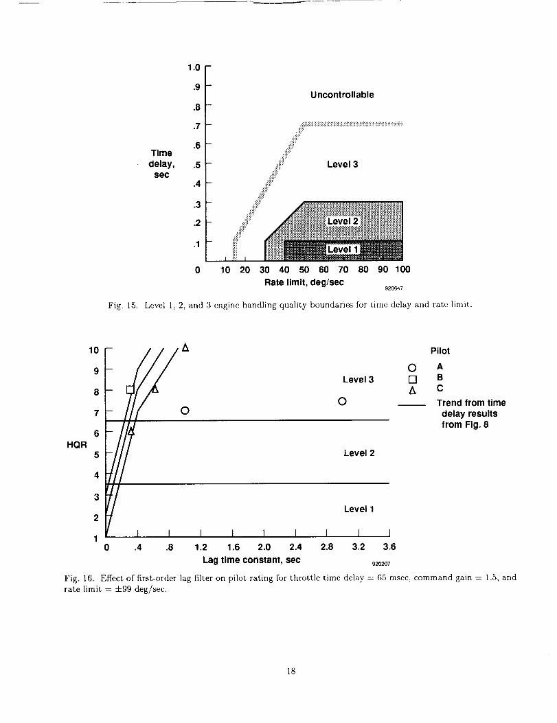
By combining the pilot ratings for time delay and
rate limit (Figs. 8 and 12), boundaries were approxi-
mated to describe level 1, 2, and 3 handling qualities.
Figure 15 shows the level of handling quality bound-
aries for rate limit versus time delay. The boundaryfor level 1 handling qualities is well defined such that
throttle time delay should be less than 100 msec, and
rate limit should be greater than 40 deg/sec. The outerboundaries between levels 2 and 3 and between level 3
and uncontrollable are not well defined and vary greatlybetween pilots. As a result, the outer boundaries shown
in Fig. 15 represent rough estimates.
Lag Filter Effect
The effects of first-order lag filters on the throttle
response handling qualities were evaluated. Unfortu-
nately, an insufficient number of lag time constantswere tested to investigate a suitable range of handling
qualities.
Figure 16 shows the effect of first-order lag filters on
pilot ratings. Except for one test point, the data re-
sulted in inadequate (level a) handling qualities. The
13

AX,g
N1,rpm
PLAFB,deg
PLACMD,deg
.4
0
_.4
80O0
7000
6000 I I 1 i L I L L L 1 !
80
40
.I t I I I i 1 I 1 1
0 5 10 15 20 25 30 35 40 45 50Time, sec _oI_
(a) Time histories of pilot A, HQR = 4.0.
AX,g
N1,rpm
PLAFB,deg
PLACMD,deg
.4
0
--.4
8000
7000
60008O
40
080
4O
0
I I I I l I I J J
5 10 15 20 25 30 35 40 45 50Time, sec _o2oo
(b) Time histories of pilot C, HQR = 5.5.
Fig. 13. Level 2 handling qualities for rate limit = +40 deg/sec and time delay = 65 msec.
same 4-1 HQR band obtained from the time delay eval-uations (Fig. 8) was superimposed on the first-orderlag evaluations. The degradation in handling qualitiesfrom increasing the lag time constant appears similar
to the degradation from increasing time delay. Variousdegrees of PIO occurred in each of the inadequate (level3) cases. The character of the amplitude and frequencyof the PIO tended to be similar to that of the +20-
deg/sec rate limit evaluations.
14

Pilot
A
C
D
AX,
g
N1,
rpm
PLAFB,
deg
PLACMD,
deg
HQR
4.0
5.5
6.0
.4
0
8000
7000
60008O
40
08O
4O
1 I 1 I I I 1 I I J
..... I ....... 1 J
_1 __ I I 1 I I I L J
F
• .... I I I I I I I I I
5 10 15 20 25 30 35 40 45 50
Time, sec920201
(c) Time histories of pilot D, HQR = 6.0.
Comments
The throttle feels like the gearing is reduced. More throttle motion is needed for a
given thrust change. Took some compensation to get enough thrust to move foreand aft. An HQR of 4 was given based on moderate pilot compensation to get
desired performance.
I'm falling into the typical trap of trying to figure out what's going on and have no
idea, so I'll admit it. The confusing thing was that there were periods where I had
pretty decent performance and then some periods of overcontrol that left me less
than happy with the predictability of the basic airplane. So the performance overall
was adequate with a reasonable amount of throttle motion. With the initial response,
it felt like I was overcontrolling it. At times, I was getting it moving when I wanted it,
but generally the final response was not as predictable as I would like. The airplane
was controllable with adequate performance.
A little bit of trouble anticipating how much power to take off and when to put it
back on as the lead aircraft made changes. The throttle had more motion than I
would have liked. Initial and final thrust responses were O.K. I might have beenoverdriving the throttle a little bit to get the amount of thrust that I wanted out of it
in both directions. Controllability was not in question, had adequate performance.
Steady state station keeping was no problem. An HQR of 6 was given based on pilot
workload. [This pilot initially rated this point as a 5, then changed it to 6.]920202
Fig. 13, Concluded.
15

AX,g
N1,rpm
PLAFB,deg
PLACMD,deg
AX,g
N1,rpm
PLAFB,deg
PLACMD,deg
Fig. 14.
0
-.4 _-----_l__L _ k___ 18000
L__J_ j
7000
6OO08O
40
080
40
--i--J-----l_____l__.J_ j
0 5 10 15 20 25 30 35 40 45 50Time, sec
9_O203
(a) Time histories of pilot B, HQR = 10.0.
J----L__l
k__l
0
-.4 ' J _--/--L___L j I I I J8000
70O0
6000 _ , , , __j
4O
0 I _J I I U [ I I J
8040
--J-__.l I I I --. I I ---J__l J
0 5 10 15 20 25 30 35 40 45 50Time, sec
_oao4
(b) Time histories of pilot C, HQR = 9.0.
Level 3 handling qualities for rate limit = 20 deg/sec and time delay = 65 msec.
16
Pilot
B
C
D
AX,
g
N1,
rpm
PLAFB,
deg
PLACMD,
deg
HQR
10.0
9.0
9.0
.4
0
--.4
8000
7000
600080
4O
08O
4O
0
.... I I I I L I
I I I I I I t I I J
5
I
10• I I I I L_ __ I I _.__
15 20 25 30 35 40 45 50
Time, sec920205
(c) Time histories of pilot D, HQR = 9.0.
Comments
Even for the steady state station keeping I'm making pretty big inputs and lots of
motion and not getting the response I expected. There was a PIO tendency. With
the lead aircraft changing thrust, I'm just stop-to-stop with the throttle. I have to
give that an HQR of 10. If you were on a boom, you'd be off it pretty quick. You'dhave a hard time staying with the guy in any formation flying.
The boomer's eyes are very big! Station keeping was really no problem without the
throttle jinks. But it seemed like there was 1/2 in. to 3/4 in. of absolute deadband in
the throttle. So, I could not achieve desired performance, not even close. And, I
think I could hurt somebody. So we're talking 8, 9, or 10 again. It's not clear that I'd
have to abandon the task, but it's very close to that.
I had a lot of throttle motion anytime I wanted to do something. The initial thrust
response was pretty slow. It appeared to be some sort of a time delay or something
that exhibited time delay type characteristics. In the final response, I was never ableto nail down where I wanted to leave the throttle. There were no PIO tendencies
because I never seemed to get in any one place at any one time. The only PIO was
me moving the throttle with no apparent effects. The chase pilot and I had a little
discussion about whether that one would have damaged the tanker, and there's no
question that it would have. _o2o6
Fig. 14. Concluded.
17
Time
delay,sec
1.0
.9
.8
.7
.6
.5
.4
.3
.2
.1
0
Uncontrollable
-- ::i::ii_ii!i:!:iii:iiiii:iiiiii?_!_i?_i?_i_ii!;_i?_i!ii:_i!iii_i!iii_i!i_!iii!_iii;i:ii_!_iii_i??_i_$i$_i_:?
- ::S.::::::
- .S_:': Level 3
- .:,:j"::#,"
Sii? _l!j_iiiiiil Level 2 i/iiii/i/i/iiii/iiiiiiiiiiiiiiiii::::::::::::::::::::::::::::::::::::::::::::::: ::::::::::::::::::::::::::::::::::::::::::::::::::::::: :
I :' I .4::x_::::J2::::.._::._::::::::::::::::2::::::::::::_:'_::_._:_:i_i_$_!:!:!:!:!:!:!_!:_:!:!::::::::::::::::::_:::_::::::::::_:
10 20 30 40 50 60 70 80 90 100
Rate limit, deg/sec920647
Fig. 15. Level 1, 2, and 3 engine handling quality boundaries for time delay and rate limit.
10 A
9
8
7 O
6
HQR5
4
3
2
I
Level 3
O
Level 2
Level 1
I I
0[]A
Pilot
A
B
C
Trend from time
delay results
from Fig. 8
1 I I I I0 .4 .8 1.2 1.6 2.0 2.4 2.8 3.2 3.6
Lag time constant, sec _o_o_
Fig. 16. Effect of first-order lag filter on pilot rating for throttle time delay = 65 msec, command gain = 1.5, and
rate limit = +99 deg/sec.
18

Figure17showstimehistorydataandpilotC com-mentsfor a lag timeconstantof 0.3sec. '['his time
constant represents the only adequate (level 2) han-
dling qualities data point. The effects of the first-order
lag filter are similar in throttle motion and magnitude
to the pure time delay effects (Fig. 10(a)). Pilot C com-mented that station keeping was not too bad, but it got
worse when attempting to match throttle changes by
the lead airplane. This pilot said that the throttle felt
as though he/she were PlO'ing the throttle. Extensive
pilot compensation was required; therefore, an tIQR of
6.0 was given.
Figure 18 shows two sets of time histories of inad-
equate (level 3) handling qualities and pilot C com-
ments. Comparing Figs. 17 and 18 shows the effect
of increasing the lag time constant from 0.3 through0.6 to 1.0 see. Increasing the lag time constant sig-
nificantly increased the throttle motion by the pilot.
The pilot noted Pie and much throttle input for the
0.6- and 1.0-see lag time constant configurations. Ob-
serve that the frequency decreased from approximately
0.25 to 0.20 cycles/sec. The pilot could not control the
engine response and was from stop to stop with the
throttle (Fig. 18(b)) for the 1.0-see case. As a result,
an HQR of 10.0 was given.
Figure 19 shows two sets of time histories and pi-lot comments for lag time constants of 1.0 and 3.0 see
which describe inadequate (level 3) handling qualities
for pilot A. Note the similarity between the throttle
motions of pilots A (Fig. 19(a)) and C (Fig. 18(b)) for
a 1.0-see lag time constant. Figure 19(a) also shows
that pilot A moved the throttle from stop to stop. Pilot
comments were also similar. Pilot, A noted large thrust
delays and overshoots in both directions and was un-able to obtain adequate performance. Note that pilot
A rated this configuration a 7.0 compared to a 10.0 for
pilot C. Figure 19(b) shows a 3.0-see lag time constant
time history for pilot A. The frequency of throttle mo-tion decreased significantly from 0.2 to between 0.1 and
0.05 cycles/see. Pilot A commented that the rate wasso slow that it was impossible to stabilize the airplane
in formation and rated this configuration a 7.5.
AX,
g
N1,
rpm
PLAFB,
deg
PLACMD,
deg
.4
0
--.4
8000
7000
60008O
4O
080
40
I ..... _ L L.__ • i I I
t
___1 __ h 1_ I I L • [ I J
F
L l L._ _ k L L i i _ 1
F
I 1 I I L. L ___ L _J J
5 10 15 20 25 30 35 40 45 50
Time, sec
Station keeping isn't too terribly bad, but I'm putting in an awful lot of inputs
in the throttle, and pretty big inputs too. I'm slowly going forward and aft
with the throttle. I'm not seeing a classic Pie, but I am PIO'ing the throttle.
Things get worse when trying to match throttle changes of the lead aircraft.Deficiencies certainly warrant improvement. Extensive pilot compensation is
required. An HQR of 6 was given.920208
Fig. 1T. Time histories and pilot C comments describing level 2 handling qualities for lag time constant = 0.3 sec,
command gain = 1.5, time delay = 65 msee, and rate limit = :t:99 deg/sec.
19

AX,
g
N1,
_m
PLAFB,
deg
PLACMD,
deg
.4
0
--,4
8000
7000
600O
8O
40
0
80
40
_ J. 2_ J J 2 J .L J _- J I 1 I I I 1 ] I I
I I I I I I I 1 I I I
rI L I I I I I l ± •
5 10 15 20 25 30 35 40 45 50 0 5 10 15 20 25 30 35 40 45 50
Time, sec
(a) Lag time constant = 0.6 sec, HQR = 8.0. (b) Lag time constant = 1.0 sec, HQR = 10.0.
Lag time
constant,sec
HQR Comments
0.6 8.0 I don't know what the problem is. But every time I get in a stabilized station
keeping position, I see some acceleration or deceleration. It just falls apart on
me. It definitely needs improvement when trying to track throttle changes ofthe lead aircraft. I was really oscillating and PIO'ing and lots of throttle input.
I consider this to be a major deficiency; therefore, and HQR of 8 is given.
1.0 10.0 I really can't control it. I'm about 50 ft away and almost stop-to-stop with thethrottle now. I'm really trying to slow my gain down in manipulating the throttle,
but I'm still seeing a PIO. I have to give that a 10. I don't think that if I'd been
out over the Atlantic, and I needed fuel, I'd have been able to do that safely.
rm just seeing the throttle go stop-to-stop and that's completely unsatisfactory.920209
Fig. 18. Time histories and pilot C comments describing the effects of increasing lag time constants for level 3
handling qualities for command gain = 1.5, time delay = 65 msec, and rate limit = 4-99 deg/sec.
Lead-Lag Filter Effect
Handling quality evaluations were conducted to
study the effects of appropriate first-order lead-lag fil-
ters in combination with additional time delay. Thisstudy was to determine if suitable lead compensation
could offset the handling qualities degradation of throt-
tle system time delay.
Figure 20 shows the data obtained using the lead-lag
filter to compensate for additional time delay. Con-
figurations with 165- and 265-msec time delay were
evaluated. Superimposed on this figure is the 4-1 HQRband from Fig. 8. Unfortunately, the database for this
experiment was insufficient for use in drawing conclu-
sions. The data remained within the 4-1 HQR band.
The HQR trends suggested some improvement withthe lead compensation for the 165-msec cases, but thefew evaluations flown showed inconsistencies between
some HQR's and pilot comments. The overall ratings
remained essentially unchanged with the added lead
compensation filters for the larger 265-msec cascs.
2O

AX,
g
N1,
rpm
PLAFB,
deg
PLACMD,
deg
.4
0
--.4
8000
7000
6000
* l t l t e L I l J
80
40
0
80
40
0
i i | t t i " i i i
\_j \/L__ . • • L J.. i I t t i i
5 10 15 20 25 30 35 40 45 50
iL _ I t i i i • i i J
r
iL 1 t i t l i i i [ i
0 5 10 15 20 25 30 35 40 45 50
Time, see
(a) Lag time constant = 1.0 sex:, HQR = 7.0. (b) Lag time constant = 3.0 sex:, HQR = 7.5.
Lag time
constant,SCC
HQR Comments
1.0 7.0 There was a big delay and big overshoots in both directions. 1 couldn't do an
adequate job. Even with all that I could bring to bear on it, I couldn't get adequate
performance.
3.0 7.5 I'm not even in formation but get the impression that the rate is very slow.
Particularly when you add throttle, the rpm doesn't change very fast. I wish
you could see this on TV. This is wild. The rpm rate is so slow that it's just
impossible to stabilize this in formation. 92o2_o
Fig. 19. Time histories and pilot A comments describing the eft'cots of increasing lag time constants for level 3
handling qualities for command gain = 1.5, time delay = 65 msec, and rate limit = ±99 deg/see.
21

10
9
8
7
6HQR
5
4
3
2
1
I
I I I I I
0 .1 .2 .3 .4 .5 .6
Time delay, sec
Level 1
I I I
.7 .8 .9
920211
Pilot
[] B
A CD
[] None
• 30/20
[] 40/20
[] 50/20
• 20/10
Fig. 20. Effect of lead-lag compensation for additional time delay on pilot ratings for command gain = 1.5, timedelay =: 65 msec, and rate limit -- -t-99 deg/sec.
Concluding Remarks
A flight evaluation was conducted at the DrydenFlight Research Facility to investigate the effects of
varying engine throttle response on airplane handling
qualities. An electronic throttle control system in aTF-104G airplane was used to evaluate the effects of
throttle time delay, rate limit, first-order lag time con-
stant, and lead-lag time constant. The Cooper andHarper Pilot Rating Scale was used to describe satis-
factory, adequate, and inadequate (level 1, 2, and 3)
handling qualities. A precise longitudinal, close-wing
station keeping task was flown to simulate such oper-
ations as air-to-air reflmling and close-formation flightunder adverse instrument conditions. The formation
leader introduced small and unannounced step throt-tle changes to challenge the evaluation pilot. These
changes provided the desired degree of handling qual-ities discrimination. Highlights of tile result are sum-marized next.
For level 1 handling qualities, throttle time de-
lay should be less than 100 msee; and rate limit
should be greater than 40 deg/sec. Thrust pilot-
induced oscillations occurred for time delay valuesgreater than 250 msee and rate limits less than 25
deg/see. A steep degradation of handling qualityrating occurred with added time delay. Decreas-
ing throttle rate limits to +45 deg/sec had min-
imal effect in changing the engine handling quali-
ties. A sharp degradation in handling qualities oc-
curred with rate limit values less than +40 deg/sec.
tlandling quality ratings at -1-40 deg/sec ranged from 2
to 6, thereby suggesting initial handling quality degra-dation.
An insuflicient number of lag time constants wereevaluated for determining satisfactory (level 1) or ade-
quate (level 2) airplane handling qualities. Except for
one test point, the data resulted in inadequate (level 3)handling qualities. When the same 4-1 handling quality
rating band obtained from the time delay evaluations
was applied to the lag time constant evaluations, the
degradation in handling qualities from increasing the
lag time constant appeared similar to the degradationfrom increasing time delay.
The attempt to identify the effect of adding lead-lag time constants with additional time delay to deter-
mine if lead compensation could offset handling qualitydegradations was inconclusive. Data for the lead com-
pensation configuration remained within the 4-1 ratingband of the uncomperlsated configuration data.
References
l Burcham, l_ank W., Jr., Lawrence P. Myers,
and John R. Zeller, Flight Evaluation of Modifica-
tions to a Digital Electronic Engine Control System in
an F-15 Airplane, NASA TM-83088, 1983. (Also avail-able as AIAA-83-0537, Jan. 1983.)
2Myers, Lawrence P. and Frank W. Burcham, Jr.,
Propulsion Control Experience Used in the Highly
22

Integrated Digital Electronic ContTvl (ItlDEC) Pro-
gram, NASA TM-85914, 1984.
aWalker, Laurence A., "ltarrier II---Digital Engine
Control Flight Tests," 30lh Symposium Proceedings,
Society of Experimental Test Pilots, Sept. 24 27, 1986,pp. 49-70.
4Cooper, George E. and Robert P. Harper, .lr., 7'he
Use of Pilot Rating in the Evaluation of Aircraft Han-
dling Qualities, NASA TN I)-5153, 1969.
SNeal, Bradford and Upal Sengupta, 7"he haple-
mentation and Operation of a Variable-Response Elec-
tronic Throttle Control System for a TF- 10d G Aircraft,NASA TM-101696, 1989.
6Hoh, Roger It., "Unifying Concepts for ttandling
Qualities Criteria," AIAA-88-4328, Aug. 1988.
rU.S. Air Force, Militar?j Specification Flying Qual-
ities of Piloted Airplanes, MIL-F-8785C, Nov. 1980.
23


Form Approved
REPORT DOCUMENTATION PAGE OM8Noozo4-o788
PLIbhc teDorling burden ]or Ibis COlleCtiOn ol information is eslimaled 1o average 1 hour par response. _ncludnng the lime for reviewing mslruCtlons, searching ex=shng dais sources,
galharing arid mair_lainin_ tha data needed, and compleIing and reviaw_ng the collection o1 informatiorL Sefld commerits regatdirig lhis burden eslimats or any Other aspecl of Ih_s
COIkDctionof informatnon, including suggestions for reducing this burden, to Washington Headcluarlers Services, Directorate for intormahon Operal=ons and Raporls, 1215 JellersonDavit Highway, Suile 1204. Arlinglon, VA 22202-4302, and 1othe Office of Management and Budgel, Paperwork Reduction Pro act (0704-0188). Washmglon, DC 20503
1. AGENCY USE ONLY (Leave blank) 2. REPORT DATE 3. REPORT TYPE AND DATES COVERED
March 1993 Technical Memorandum
4. TITLE AND SUBTITLE 5. FUNDING NUMBERS
Summary of the Effects of Engine Throttle Response on AirplaneFormation-Flying Qualities
6. AUTHOR(S)
Kevin R. Walsh
7. PERFORMINGORGANIZATIONNAME(S)ANDADDRESS(ES)
NASA Dryden Flight Research FacilityP.O. Box 273
Edwards, Califomia 93523-0273
9. SPONSORING/MONITORINGAGENCYNAME(S)ANDADDRESS(ES)
National Aeronautics and Space Administration
Washington, DC 20546-0001
WU 307-05-01
8. PERFORMING ORGANIZATIONREPORT NUMBER
H-1880
10. SPONSORING/MONITORINGAGENCY REPORT NUMBER
NASA TM-4465
11. SUPPLEMENTARY NOTES
Presented as AIAA-92-3318 at the AIAA 28th Joint Propulsion Conference and Exhibit, July 6-8. 1992,
Nashville, Tennessee.
12a. DISTRIBUTION/AVAILABILITY STATEMENT
Unclassified -- Unlimited
Subject Category 08
12b. DISTRIBUTION CODE
13. ABSTRACT (Maximum 200 words)
A flight evaluation was conducted to determine the effect of engine throttle response characteristics
on precision formation-flying qualities. A variable electronic throttle control system was developed and
flight-tested on a TF-104G airplane with a J79-11B engine at the NASA Dryden Flight Research
Facility. This airplane was chosen because of its known, very favorable thrust response characteristics.
Ten research flights were flown to evaluate the effects of throttle gain, time delay, and fuel control rate
limiting on engine handling qualities during a demanding precision wing formation task. Handling
quality effects of lag filters and lead compensation time delays were also evaluated. The Cooper and
Harper Pilot Rating Scale was used to assign levels of handling quality. Data from pilot ratings and
comments indicate that throttle control system time delays and rate limits cause significant degradations
in handling qualities. Threshold values for satisfactory (level 1) and adequate (level 2) handling
qualities of these key variables are presented. These results may provide engine manufacturers with
guidelines to assure satisfactory handling qualities in future engine designs.
14. SUBJECT TERMS
Electronic engine control system; Engine throttle response: Formation-l'iyingqualities; Handling qualities criteria: Throttle variables
17. SECURITY CLASSIFICATION 18 SECURITY CLASSIFICATIONOF REPORT OF THIS PAGE
Unclassified Unclassified
NSN 7540-01-280-5500
15. NUMBER OF PAGES
2816. PRICE CODE
A03
19. SECURITY CLASSIFICATION 20. LIMITATION OF ABSTRACTOF ABSTRACT
Unclassified Unlimited
Standard Form 298 (Rev 2.89_,Prescribed by ANS_ Sto Z39-18
298102
NASA- Langley, 199:1


