
Summary of ’Production of Aerospace Materials’ · strength than birds. Nevertheless, the...
56
Summary of ’Production of Aerospace Materials’ Marco Delgado Schwartz November 6, 2016
-
Upload
duongxuyen -
Category
Documents
-
view
220 -
download
0
Transcript of Summary of ’Production of Aerospace Materials’ · strength than birds. Nevertheless, the...

Summary of ’Production of Aerospace Materials’
Marco Delgado Schwartz
November 6, 2016

Contents
1 Notes from the Author: 3
2 Introduction: 42.1 General background: . . . . . . . . . . . . . . . . . . . . . . . . . 42.2 Advances in aerospace structures and materials: . . . . . . . . . . 5
3 Overview: 7
4 Cutting 84.1 Separating multiple parts, no chips . . . . . . . . . . . . . . . . . 84.2 Separating multiple parts with chips . . . . . . . . . . . . . . . . 11
4.2.1 Laser Cutting . . . . . . . . . . . . . . . . . . . . . . . . . 124.2.2 Electrical discharge wire cutting . . . . . . . . . . . . . . 134.2.3 Water jet cutting . . . . . . . . . . . . . . . . . . . . . . . 144.2.4 Abrasive water jet cutting . . . . . . . . . . . . . . . . . . 15
4.3 Machining (single part and chips) . . . . . . . . . . . . . . . . . . 164.3.1 Turning . . . . . . . . . . . . . . . . . . . . . . . . . . . . 174.3.2 Milling . . . . . . . . . . . . . . . . . . . . . . . . . . . . . 17
5 Liquid Phase Processing 205.1 Casting . . . . . . . . . . . . . . . . . . . . . . . . . . . . . . . . 20
5.1.1 Sand casting: . . . . . . . . . . . . . . . . . . . . . . . . . 215.1.2 Investment Casting . . . . . . . . . . . . . . . . . . . . . . 255.1.3 Certification . . . . . . . . . . . . . . . . . . . . . . . . . 25
5.2 Liquid phase processing of polymers . . . . . . . . . . . . . . . . 255.2.1 Injection molding . . . . . . . . . . . . . . . . . . . . . . . 26
6 Forming Processes 286.1 Important principles of deformation . . . . . . . . . . . . . . . . 286.2 Metal forming . . . . . . . . . . . . . . . . . . . . . . . . . . . . . 29
6.2.1 Rubber forming . . . . . . . . . . . . . . . . . . . . . . . . 306.2.2 Forging . . . . . . . . . . . . . . . . . . . . . . . . . . . . 30
6.3 Processes for Thermoplastic and Thermoset Composites . . . . . 326.3.1 Important aspects . . . . . . . . . . . . . . . . . . . . . . 326.3.2 Lay up . . . . . . . . . . . . . . . . . . . . . . . . . . . . . 336.3.3 Resin Transfer Molding . . . . . . . . . . . . . . . . . . . 356.3.4 Vacuum Infusion . . . . . . . . . . . . . . . . . . . . . . . 376.3.5 Forming of Fiber Reinforced Thermoplastics . . . . . . . 37
1
7 Assembly of aircraft 387.1 Mounting division . . . . . . . . . . . . . . . . . . . . . . . . . . 397.2 Manufacturing division . . . . . . . . . . . . . . . . . . . . . . . . 397.3 Assembly jigs . . . . . . . . . . . . . . . . . . . . . . . . . . . . . 40
8 Riveting and Bolting 428.1 Rivets . . . . . . . . . . . . . . . . . . . . . . . . . . . . . . . . . 428.2 Bolts . . . . . . . . . . . . . . . . . . . . . . . . . . . . . . . . . . 42
9 Adhesive bonding and Welding 439.1 Adhesive bonds . . . . . . . . . . . . . . . . . . . . . . . . . . . . 439.2 Welding . . . . . . . . . . . . . . . . . . . . . . . . . . . . . . . . 43
10 Quality 4410.1 Quality terms . . . . . . . . . . . . . . . . . . . . . . . . . . . . . 4510.2 Product Realization . . . . . . . . . . . . . . . . . . . . . . . . . 46
10.2.1 Product focused . . . . . . . . . . . . . . . . . . . . . . . 4610.2.2 Process focused . . . . . . . . . . . . . . . . . . . . . . . . 4610.2.3 System focused . . . . . . . . . . . . . . . . . . . . . . . . 4710.2.4 Chain focused . . . . . . . . . . . . . . . . . . . . . . . . . 4710.2.5 Total quality . . . . . . . . . . . . . . . . . . . . . . . . . 47
10.3 Inspection . . . . . . . . . . . . . . . . . . . . . . . . . . . . . . . 4710.4 Testing . . . . . . . . . . . . . . . . . . . . . . . . . . . . . . . . 48
10.4.1 Visual Inspection . . . . . . . . . . . . . . . . . . . . . . . 4810.4.2 Ultrasonic Inspection . . . . . . . . . . . . . . . . . . . . . 4810.4.3 Acoustic Emission Analysis . . . . . . . . . . . . . . . . . 4910.4.4 Thermography . . . . . . . . . . . . . . . . . . . . . . . . 4910.4.5 Fluorescent Penetrant . . . . . . . . . . . . . . . . . . . . 4910.4.6 Magnetic Ink . . . . . . . . . . . . . . . . . . . . . . . . . 4910.4.7 Eddy Current Technique . . . . . . . . . . . . . . . . . . . 5010.4.8 Radiography . . . . . . . . . . . . . . . . . . . . . . . . . 5110.4.9 Hardness Testing . . . . . . . . . . . . . . . . . . . . . . . 51
11 Lean Manufacturing 5211.1 Different forms of waste: . . . . . . . . . . . . . . . . . . . . . . . 5311.2 Value . . . . . . . . . . . . . . . . . . . . . . . . . . . . . . . . . 5411.3 Lean Methods . . . . . . . . . . . . . . . . . . . . . . . . . . . . . 5411.4 Common Lean Methods . . . . . . . . . . . . . . . . . . . . . . . 55
12 Organization 56
2

Chapter 1
Notes from the Author andoverview:
The purpose of this document is to provide to the student a summary of themost important items of the reader used in the TU Delft 3rd year course ”Pro-duction of Aerospace materials”. Note that during this course you will have tolearn a lot of vocabulary and keep in mind all the different processes.
That is why the main goal of this document is to facilitate your learning ofall the keywords with the use mnemonics. These mnemonics have helped me tolearn the vocabulary quite fast and retain most of it successfully already afterthe first go. Reviewing it is facilitated by the images, where one image canbe the key to remembering several keywords. You may want to use the samemnemonics or replace them with your own. It helps a lot!
In the first chapters manufacturing techniques are discussed. These can besummarized as follows:
• Casting and injection processes, where liquefied material fills the cavity.
• Shearing processes such as cutting and machining, where material isremoved (or cut). The final part consists of the remaining material.
• Forming processes, where applied forces deform the material into thedesired product.
• Assembly: A part made of multiple joined sub-parts.
The assembly section is followed by the chapter of riveting and bolting as wellas adhesive bonding and welding. These two chapters are quite well describedin the reader and thus are not declared again in this document.
The final parts go over management topics describing quality control, leanmanufacturing and organization.
3
Chapter 2
Introduction:
2.1 General background:
Due to the massive requirements that our society requires to function properlyand in harmony with nature, production and manufacture of materials playsa huge role to maintain this equilibria. Aerospace engineers, with the mindalready set a light weight and efficient structures/machines, have made consid-erable progress in this area. In fact, the aerospace industry will always be atthe forefront of lightweight technological developments and applications.
From an historical point of view, new materials and technology allowed ofcourse new creations, but it also opened new possibilities for the previous ma-terials/technology.
Case study: As an example the mosquito is mentioned, an aircraft thatin combination with the newly commenced metal technology was buildmainly of wood, proving to be one of the most successful aircraft in WWII, superior to many metal aircraft it had to compete with.
In addition the application of mathematics and other have improved the pro-duction of structures with far more reliability (instead of trial and error and notbeing able to describe unexpected events).
Finally, the engineers are not only meant to look for a technical solution toa problem, however must be able to trade off between different solutions. Theapplication of organized research, only more or less applied after the Wrightbrothers success and the entering of the World wars (around 1914), has made itpossible to make huge advancements in science and technology. (Before inven-tions in the field of aerospace were more of a random hobby which often wouldtake their inventors to their death due to failures). Companies of different scalesand purposes would emerge and start taking part in the innovation process ofairplanes. (A few examples of companies are shown in the book at chapter 1.6)
4

2.2 Advances in aerospace structures and mate-rials:
Every airplane requires a system of different aspects that have to work together.In fact, the dependency of each aspect is so important that an improvement ofone part can have an impact on the rest of the airplane. In the following someof the important developments are mentioned below, more or less in order oftheir appearance.
• Engines:
Case study: Before the first flying machines lots of inventorsthought humans should be able to fly due to their far greaterstrength than birds. Nevertheless, the strength to weight ratio of ahuman is far lower than the one of a bird, as well as that the birdsheart beats at around 800 beats per minute, much more efficientthan a human. The requirement of greater strength while focusingon being lightweight needed the application of aero-structures (inorder to be able to hold wings) as well as in the form of propulsion(such as engines).
The Wright brothers had made their first successful aircraft.Before it could fly though, they had to invent and apply a newengine that was light and strong enough to be used on theirairplane. Only through the technological advancement there, theirairplane was possible to fly successfully.
• Wire braced structures: Components are held together with wires to makethem lightweight. In combination with two wings on top of each other,biplanes could be built.
• (Semi) monocoque structures: Wire braced structures didnt allow the useof the space inside efficiently, a problem as planes got larger and startedtransporting. The application of the ’stressed skin’, where the skin takespart in holding the structure allowed planes to be built much more spaceand material efficient. The American aviation industry applied this ideaalso to the wings, allowing large capacity fuselages.
• Airfoils: Another important improvement of airplanes was the applicationof thick airfoils, which not only had a better aerodynamic performance, butimproved the wing structure, saving a lot of weight and allowing greaterand faster airplanes (as they e.g. did not need two wings anymore).
• Wooden aircraft: From 1915-1935 the major material used on airplaneswas wood, moving from open to closed structures. (At first bamboo wasused, which later on moved to spruce due to being lighter, stronger andeasier to produce). Production facilities were created that dealt with thesophisticated wood crafting. The research and progress made in this areaallowed state of the art airplanes like the mosquito as mentioned before inthis chapter (case study).
5
• Metal constructions:
Case study: The move to metal constructions was caused partlydue to political views, that regarded this as the material of thenew era, leaving wood as something from the pre era. Additionallydue to the world wars, wood became scarce and too slow to manu-facture, thus requiring the application of metals. (Junkers: ’metalcan be given any desired shape and dimension compared to wood,is more reliable, stronger and less sensitive for corrosion...’)Thiswas at a cost of some very promising wooden projects, but gaveway to new machines/industries; still busy today in the researchof these types of materials. Finally, in March 1931 a three engineFokker (made of wood) crashed due to moisture weakening the glueholding the wings. The consequence was the requirement of severalmore routine inspections on the aircraft, which drove the costs ofmaintaining such aircraft up high, giving a boost to metal aircrafts.
• Production companies: Given the world wars and other requirements ofairplanes, companies were created that would put together the variousdisciplines such as research, design and manufacture.
Case study: A huge growth in airplane production was created,such as in England, where in 1914 only few hundred people workedwith aircrafts, in 1918 it had increased to 350’000!
Being a company though also forced the construction of airplanes thatwould always be at the state of the art by combining all disciplines together(material choice, manufacture, computer simulations, etc.) in order tocompete in the market.
• Further improvements: With the success of the DC-2 and DC-3, metalsemi monocoque structured airplanes, these became a standard in aerospaceengineering. Further improvements continued with the reduction of riv-ets, improving fail safe structures and further research in new materialsfor better material efficiency.
• Applying fibres: The application of fibres due to their great material prop-erties has allowed to make structures lighter and smoother. They havethough weaknesses such as not being able to plastically deform, whichcauses safety issues to take into account.
• Applying sandwich structures: Sandwich structures are applied to increasethe moment of inertia of the skin and improve its rigidity. Although ex-tremely efficient, its construction and production is limited and compli-cated and thus still mainly used on small parts.
6

Chapter 3
Cutting
There are three types of cutting processes:
• Separating multiple parts with no chips such as shearing and punching
• Separating multiple parts with chips such as sawing and laser cutting
• Machining (single part and chips) such as milling and drilling
3.1 Separating multiple parts, no chips
During this process, shearing is used (through a cutting blade or a punch anda die, similar to scissors and a paper punch) to separate parts. This does notcreate any chips, but does create rough surfaces or other defects and usuallyrequires further machining.
Keyword: Shearing; the general process of using shear forces to sepa-rate parts.
One can distinguish between two different shear processes, punching and blank-ing. In punching the sheared slug is discarded, in blanking it is the part andthe rest is scrap.
7

Keyword: Punching; works similar to a paper punch. What you punchbecomes scrap, just like when you hit someone in the face.
Keyword: Blanking; similar to a paper punch, but in this case thepunched part is the product. The doctor only cares about the punchedface of the ’blanked’ out guy, not the rest of the body.
Keyword: Slug; the part that gets punched. After the punch the facelooked as disgusting as a big fat slug.
During the process of shearing, there are three steps that cause the final cut:
• Indentation, its depth into the sheet is called roll over depth.
• Cutting, its depth is called Burnish depth and has a smooth finish due tothe sliding of the sheet against the punch/blade. Ductile materials have ahigher Burnish depth.
• Final shearing, its depth called fracture depth. This part of the sheet isrough and ends with a burr. The burr height increases with the clearancebetween the punch and die and the material ductility. Its size can be aproblem for subsequent operations.
These produce a final cut product as the schematic shown. The equipmentusually consists of a press with a punch and a die, where the material is laidand lubrication is added. The process is finished with some deburring equipmentto smoothen the edges of the products. Here the major processing parameters:
• Shape of punch and die. Bevelling is the process in which the punch ordies are shaped at an angle. This reduces the force required to cut thematerial and noise made, while ensuring a better cut quality. Symmetricbevelling eliminates also lateral forces acting on the punch or die.
• Material of punch and die or the material laid. Cutting brittle materialcan cause small cracks which could reduce the fatigue resistance of thematerial. A good finish can reduce this risk. Composite materials also
8

tend to delaminate when punched or blanked or act abrasive on the cuttingtools.
• Lubrication between punch and die. The reduction in friction allowsclean cuts and a reduction in tool wear.
• Clearance between punch and die. Typical clearance is around 2-8% ofthe sheet thickness. Softer material have smaller clearances.
• Nesting, highly important to reduce scrap material as much as possible.On the minimum side though, the material should not be drawn into theof the die, the ligaments should not fail, and no excessive burrs shouldoccur while also guaranteeing the safety of the operator.
• Deburring and Shaving; used to smoothen the edges.
9
This process is often used for pre-processing and making small or large productseries with a high cut accuracy. The time required is short, but the process canmostly be dedicated only to sheets. Other limitations are the sheet thickness(0.3 - 15 mm) and the unsuitable choice for cutting continuous fibre reinforcedpolymers.
Keyword:Burr; the excess material perpendicular to the sheet surfacecreated by shearing process. Biting straight into a ’burr’ito leaves edgeson the side.
Keyword:Blank; the slug after blanking, used as a product. The doctorleft his face as a clean and ’blank’ product.
Keyword:Bevelling; angling the punch or die to reduce cutting forceand increase cut quality. Adopting a better angle allows you to ’be well’.
Keyword:Burnished; the Burnish dimension/depth/surface. Its sosmooth you can use the surface to shine the light on paper and ’burn’it.
Keyword:Fracture depth and Breakout dimension. You use the roughsurface of a stone to fracture the prison wall and break out.
Keyword:Dishing; the slug is curved after leaving the press. This iscalled dishing. The product of a shearing process can later be used as’dishes’.
3.2 Separating multiple parts with chips
Another method to separate parts is by removing a narrow zone (kerf) in be-tween. The removal of material can be done in several ways:
• mechanically, like sawing, grinding, water jet cutting, where chips arecreated and removing them.
• thermally, like plasma arcs, lasers, electron beams, electrical charges,where the material is evaporated, melted or burned away.
Keyword:Kerf, the narrow zone where material is removed to split apiece. You can only cut straight into the wood. The lack of ’curv’esmade us want to call that straight a ’kerf ’.
Here a short summary on the different more elaborate methods used to cutpieces by removing material:
10

3.2.1 Laser Cutting
• Laser Cutting uses optical energy on the surface of the work piece to meltor evaporate portions of it. The kerf is typically 0.2mm wide. Unfortu-nately, the laser itself is at most 10% efficient and the laser has to be closeto the material (0.5mm), making 3D laser cutting very expensive.
• It can cut metallic and non metallic materials. One has to pay attentionto the reflectivity (aluminium can give problems!) and thermal conduc-tivity as well as the specific and latent heats for melting and evaporatingprocesses. The lower each of them, the better.
• May be used in combination of suction process or gas stream to improveenergy efficiency. Gases like oxygen, nitrogen or argon are used. Inertgases are used for metals to leave an oxide free edge.
• The process is numerically controlled through a computer for accuratecontrol.
• Can cut plates as thick as 32mm (although due to focusing thick plateswill be finished with a taper) and with a minimum radius till 0.005 mm.One should pay attention to high local temperatures as they may heattreat the metals or in the case of composites degrade or burn at the edges.
• The equipment cost is high, since it requires computers and a large energyfeed (due to inefficient lasers). However from then on, the costs drasticallydrop, such as for labour, raw material cost and programming. Addition-ally, the flexibility this process offers with different materials and the lowset up times make it capable to compete in the market.
11

3.2.2 Electrical discharge wire cutting
• Electrical discharge wire cutting is based on the erosion of metals by sparkdischarges. Charging the metal work piece (needs to be conductive!) and awire (made of brass, copper, tungten, etc.), the wire can be passed throughthe material while creating sparks which act like saw tooth (similar tocontour cutting with a band saw).
• This process allows to cut plates as thick as 300mm at an incredible ac-curacy of up to 2.5 µm. Although slow (5-6 mm/min) it is very flexibleand since it doesnt involve mechanical energy, properties such as hardnessand toughness of the workpiece dont affect the removal rate. (Useful forproducing products like punches and dies).
• The removal rate and surface roughness increase with increasing currentdensity and decreasing frequency of sparks. Also, the melting and latentheats of the material, their increase will cause a decrease in the rate ofmaterial removal.
12

3.2.3 Water jet cutting
• Water jet cutting makes use of the force delivered by a jet of water to cutthrough work pieces. A pressure level of 400 MPa (4000 bar) is generallyrequired in order to propel the water to speeds up to Mach 2 and 3, leavinga nozzle diameter in the range of 0.05 - 0.4mm.
• This process can only cut ’soft’ materials such as foam, soft rubber, paper,leather, etc. In order to cut stronger materials, abrasive particles areadded to the water, creating a new process: abrasive water jet cutting.
• During this process no heat is produced, thus heat sensible materials won’tbe affected.
• The orifice of the nozzle is usually made of very hard materials such asrubies (50 to 100 cutting hours) and diamonds (800 to 1200 cutting hours,but 10 to 20 times more expensive).
13

3.2.4 Abrasive water jet cutting
• Abrasive water jet cutting is similar to water jet cutting, except that fineabrasive particles are added. Their roughness/size is similar indicated aswith sandpaper, 120 Mesh making smooth surfaces and 50 Mesh makingrough, fast cuts.
• The wear occurs mostly in the mixing tube, not the orifice.
• Most materials can be cut with an abrasive water jet, such as steel, alu-minium, ceramics, glass, etc. In the case of composites though there mightbe a risk of delamination, especially if the cut is not started from the edge.
• A typical occurrence is the jetlag, where the jet of water is bent, sinceit does not have any bending stiffness. Therefore cutting through cornerswill leave behind tapers. The moving rate can be decreased, however onemay also risk kickbacks, where the jet is deflected into a different path.
• It has the ability to cut a kerf of 0.75 mm through a thickness up to 25cm.
14
3.3 Machining (single part and chips)
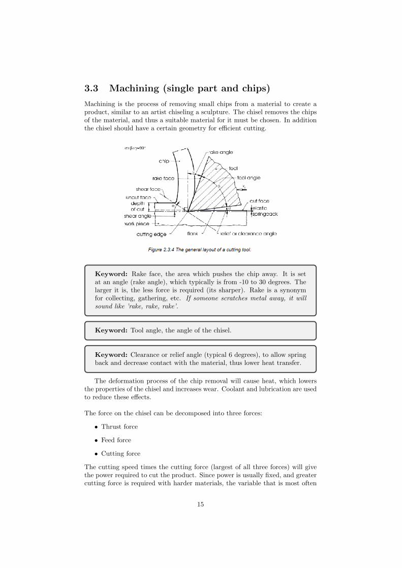
Machining is the process of removing small chips from a material to create aproduct, similar to an artist chiseling a sculpture. The chisel removes the chipsof the material, and thus a suitable material for it must be chosen. In additionthe chisel should have a certain geometry for efficient cutting.
Keyword: Rake face, the area which pushes the chip away. It is setat an angle (rake angle), which typically is from -10 to 30 degrees. Thelarger it is, the less force is required (its sharper). Rake is a synonymfor collecting, gathering, etc. If someone scratches metal away, it willsound like ’rake, rake, rake’.
Keyword: Tool angle, the angle of the chisel.
Keyword: Clearance or relief angle (typical 6 degrees), to allow springback and decrease contact with the material, thus lower heat transfer.
The deformation process of the chip removal will cause heat, which lowersthe properties of the chisel and increases wear. Coolant and lubrication are usedto reduce these effects.
The force on the chisel can be decomposed into three forces:
• Thrust force
• Feed force
• Cutting force
The cutting speed times the cutting force (largest of all three forces) will givethe power required to cut the product. Since power is usually fixed, and greatercutting force is required with harder materials, the variable that is most often
15

changed is the cutting speed. Controlling it visually helps, since it is usuallydesirable to have discontinuous chip removal. Depending on the hardness ofthe material, one may require also different types of chisels made of differentmaterials and coatings. For very hard materials ceramics can even be used,however they are only suitable is no shocks are present during cutting. Belowa figure laying out some of these options: In general machining only requires
an initial high cost for the equipment and all other costs remain low from thenon, however this is a process that usually is only used for small to moderatequantities. If added automation, the process can be sped up even more andmore products can be made at very high accuracy.
All in all there are three basic ways to machine the parts: Turning (lathing) ormilling.
3.3.1 Turning
During turning the work piece is rotating and the chisel is pushed into it. Therevolutions per minute times the diameter equals the cutting speed. It is impor-tant to note that the smoothness of the surface is dependent on two things: Thewear of the chisel, responsible for the smoothness in the direction of rotation,and the feed speed, responsible for the smoothness in the axial direction. Toguarantee also that the work pieces don’t wobble during rotation, the pieces areclamped with very stiff clamps from the lathing machine.
3.3.2 Milling
Milling is used for non rotational products and thus has a larger range of possi-ble products. In this case, the work piece remains fixed, while the milling toolis translated. Note that there are two ways to mill, slab and face milling.
In the case of slab milling, when looked closely to the cutter, one can rec-ognize the angles mentioned before for the chisel. In the case of face milling,mostly the perimeter performs the cuts. Of course, there are still a few other
16

17

tools, each having their purpose during milling operations. It is crucial howeverfor the production of these tools that they are made precise.
An important addition to the milling processes is drilling, sometimes also madewith a separate machine. Since holes are common in structures, drilling iswidely applied. Observe how once again we can find the chisel geometries: No-
tice as well that in the middle, cutting is more difficult due to low cutting speed.
If two the holes or columns it is wished to add threading, one has to use tapsand screw plates. (This can also be done with lathing. )
Keyword:Tap; used to make an internal threading. When you open the’tab’, the water goes inside the sink.
Keyword:Screw plate; used to make an external threading. When youwash the ’plates’ you put them outside of the sink.
One last alternative for the milling machine is the use of a grinder, usedto finish products. In this case the heat is one important factor to take intoaccount (due to rake angle being negative as low as -60 degrees or more), as itcould melt the surface and make the grinder ineffective. Adding a coolant tometals like aluminum will avoid this. If done properly, the heat, although high,is carried away by the chips, and thus only a fraction of the heat produced isconducted to the work piece. (Cutting speeds are very high, 30 m/s, and theremoved layer is much smaller than e.g. milling)
18

Chapter 4
Liquid Phase Processing
Liquid Phase Processing is the process in which a material is used in its liquidstate to shape it to the end product. This process is different with metals (cast-ing) than with polymers, but they both make use of molds, dies and similar.The difference in the process in mainly made due to the viscosity of the liquidmaterial, some of which will flow by themselves, some will require the additionof forces.
First the metal processing shall be discussed, then the polymer will be reviewed.
4.1 Casting
Casting is the process in which molten metal is poured into a mold, left forcooling, and finally the product is recovered by separating it from the mold.
Keyword: Foundry, the place where casting products are made. At thefoundry the make yummy metal ’fondue’.
Important aspects in molding are the temperature such as the melting tem-perature of the material and the pressure.
Case study: Low melting point materials allow metallic molds. Youcan cast aluminum in steel molds, however this is not possible with steelin steel molds. For this one would require a ceramic mold, which can beas simple as a sand mold.
All molds can withstand low pressure, however to increase production rate,pressure may be applied, in which ceramic molds wont be an option, since theyare too brittle to use. Ceramic molds tend to be however cheaper, and thusdepending on the product series, one will have to choose between the two types:Expendable molds (ceramic, sand, plaster, etc.), permanent molds (metal, com-posites of metal and graphite, etc.).
In addition, there is the option to choose between perishable molds and reusable
19
ones. Perishable molds allow a greater freedom of geometrical features, sinceone can damage the mold when removing it from the product.
4.1.1 Sand casting:
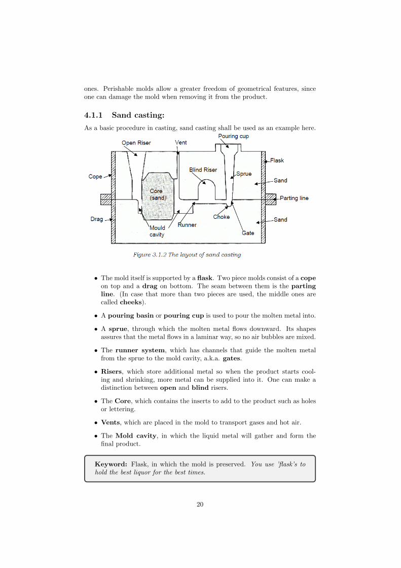
As a basic procedure in casting, sand casting shall be used as an example here.
• The mold itself is supported by a flask. Two piece molds consist of a copeon top and a drag on bottom. The seam between them is the partingline. (In case that more than two pieces are used, the middle ones arecalled cheeks).
• A pouring basin or pouring cup is used to pour the molten metal into.
• A sprue, through which the molten metal flows downward. Its shapesassures that the metal flows in a laminar way, so no air bubbles are mixed.
• The runner system, which has channels that guide the molten metalfrom the sprue to the mold cavity, a.k.a. gates.
• Risers, which store additional metal so when the product starts cool-ing and shrinking, more metal can be supplied into it. One can make adistinction between open and blind risers.
• The Core, which contains the inserts to add to the product such as holesor lettering.
• Vents, which are placed in the mold to transport gases and hot air.
• The Mold cavity, in which the liquid metal will gather and form thefinal product.
Keyword: Flask, in which the mold is preserved. You use ’flask’s tohold the best liquor for the best times.
20
Keyword: Cope, the upper mold piece. The ’cop’, ’on top’ of hismassive motorcycle.
Keyword: Drag, the bottom mold piece. The cops motorcycle is so big,it produces massive amounts of ’drag’.
Keyword: Pouring cup and sprue, where the metal is poured into.The cop refills his motorcycles tank by ’pouring cups’ of fuel through the’sprue’. Once it full, the motorcycle tank indicator blinks the word ’true’.
Keyword: Runner and Gates, the pathways for the liquid metal to pass.As the cop is refilling his motorcycle, a ’runner’ with stolen money runsby and away through a ’gate’ to the nearby forest.
Keyword: Riser, space to store extra liquid metal. The cop, in actionof the lost runner, writes flyers with a ’rise’ on the money award forwhomever would catch him, hanging them in the forest.
Keyword: Core, an ’inner’ mold to add hollow features to the productsuch as holes. Finally the cop finds in the ’core’ of the forest the runner.
Inside the flask there is cop riding his massive motorcycle which producesmassive amounts of drag. He fills his motorcycles tank by pouring cups of fuelinto the sprue. Once the tank is full, the motorcycle indicator blinks ’true’.As the cop is standing there, a runner with stolen money runs along and awaythrough a gate into the forest. The cop, in action of the lost runner, goes tothe forest and hangs flyers with a rise of money to whomever would find him.When arriving to the core of the forest, he finally finds the runner.
21

One starts inserting a pattern into the flask, after which the flask is filledwith sand. The sand is then compacted with e.g. hands or other. One canchoose between a one piece pattern or split pattern. It may be necessary toadd draft angles to the pattern to ensure easy removal from the sand molds.
For the actual casting process a few more things have to be taken intoaccount:
• The flow of the metal depends on its material properties such as viscosity(the lower, the easier the metal flows) and the surface tension (the lower,the better achievable details are possible).
• The cooling speed influences the solidification of the metal (alloy) and theprocess time (the lower, the cheaper the process). During solidification themetal will shrink (10 - 20 mm/m), reason why the mold cavity is largerthan the actual product. To avoid hot tears during shrinkage, the moldshould be allowed to be collapsible.
• The cooling direction should go from bottom up, such that the riser keepsfeeding liquid metal into the product while it cools and shrinks. Also partsthat are further away should cool first, so that the riser keeps effective.
• Parts should have the same thickness throughout if possible. A change inthickness means that the larger part will take more time to cool down, ahot spot, which means solidification will be different and affect the materialintegrity. (Microporosity can be expected). If the thickness cannot bechanged, local cooling might also help, a.k.a. chill.
• Large flat areas should also be avoided, as they tend to warp after cooling.If other high stresses are expected on the part after casting, they may berelieved through heat treatment afterwards.
22

• Most sand casting operations use silica sand (SiO2) since its commonand easy to handle while being resistant to high temperatures. To selectthe sand it must have enough strength so it wont change during casting,permeable to allow gases and steam to escape, collapsable to allowcasting to shrink and avoiding hot tears and surface quality to minimizethe need for finishing the product.
• As the smoothness of the finishing product increases, more attention willhave to be put on allowing gases to escape.
If these are not taken into consideration, failures such as hot tearing may occur,in which local shrinkage is obstructed, resulting large stresses and ultimatelyending with cracks (and making the product often unusable).
23

4.1.2 Investment Casting
In the aerospace industry, what is more often used than sand casting is invest-ment casting. Sand casting is not a feasible option for the often needed thinthickness, but in addition allows the casting of multiple parts at the same time.
This process is also sometimes called lost-wax process, since the pattern is madeof wax. These parts can be connected into a tree, after which it is coated witha ceramic. Later on, the ceramic is heated up, thus all wax is melted away, andwhat is left is a ready to use mold. The metal is poured in and once cooled, theceramic is broken down through vibrations. A high accuracy can be obtainedfrom this process. Sometimes instead of wax polymers are used since they areless delicate, however polymers are harder to remove and reuse.
4.1.3 Certification
To use cast products in aircraft/spacecraft, certain JAR/FAR requirements ap-ply. The structural elements are classified as:
• Class 1: Critical single load path
• Class 2: Critical multiple load path
• Class 3: Non critical
A sub-classification is added, since castings may have internal flaws (e.g. microporosity). That is why an extra casting factor is added to the safety factor ofthe part.
• Subclass A: 1.00 ¡= Casting factor ¡ 1.25
• Subclass B: 1.25 ¡= Casting factor ¡ 1.50
• Subclass A: 1.50 ¡= Casting factor ¡ 2.00
• Subclass A: 2.00 ¡= Casting factor
4.2 Liquid phase processing of polymers
The liquid phase process of polymers is different for the thermosets and ther-moplastic polymers. Also, since the material properties of polymers are much
24

lower than that of metals, they are not used as structural elements in aerospace.However adding fibers the mechanical properties can be increased a lot moretowards attractive alternatives from metal.
An important parameter to keep in mind though is the viscosity. Metals have alow viscosity and flow easily, and monomers may behave similarly, but polymerswill behave very viscous. Adding fibers will increase the viscosity even further.One comes to the point where one is not processing a liquid anymore, butrather a soft solid. For example the difference betweeninjection molding andcompression molding is the viscosity of the material handled. (Compressionmolding is considered in a later chapter).
4.2.1 Injection molding
Injection molding is the process in which a liquid thermoset or molten thermo-plastic polymer is squeezed through an opening into a mold.
This process only allows short fiber reinforcement, as the screw would de-stroy all longer fibers. The reinforcement is fed directly with the Most of thetime glass fibers are used, since they are low cost. Another option to add rein-forcement to the polymer is to put the fibers in the mold and fill it then withthe polymer. This method is called over-molding and also allows the appli-cation of long fibers. This is a very cost effective method that allows complexstructures to be produced fairly easy.
In general, the equipment cost of this process is quite high, since large forcesmust be used to extrude the polymers, same with the molds. In addition, glassfibers are expensive in comparison to metals (per unit of weight), thus the rawmaterial is also on the moderate to high side. Fortunately though the labor costis low, and thus, if the product series is large and the cycle time is short, thisprocess can become profitable. In addition the waste of the material is minimalwhile highly accurate products can be produced, thus making it a useful pro-duction alternative.
In addition, the following considerations must be taken into account:
• Temperature control is very important. Not controlling this correctlycould lead to e.g. premature curing (thermosets).
• For easy extraction of the product from the mold, draft angles should beadded.
25

• The merging of flow fronts of either polymers will produce knitlines, inwhere no of the reinforcements will be in between, resulting in a weaksection.
• The reinforcement of polymers consists of chopped fibers, which gets fur-ther chopped into smaller pieces by the screw. When the size of thereinforcement gets reduced so small that its similar to in all directions,the reinforcement is becomes useless and only acts as a filler.
• The orientation of the reinforcement fibers will cause an increase in strengthin one direction while perpendicularly the product will act weakly. Theorientation of the fibers can be controlled within limits.
Thermoset
The screw of the extruder mixes the monomers of the thermoset with coloragents and reinforcements. To avoid premature polymerisation, the mixturemust be kept cool. After that, the mixture is injected into the heated mold,where it spreads inside and cures. It may be possible that gases are producedduring the process, and thus ventilation must be taken into account. Once done,the product is pushed out of the mold.
Thermoplastic
Thermoplastics need to be heated before they can be processed. To speed upthe heating, the material is provided in granulates. In addition, the move-ment and compression of the feed hopper and screw will cause due to shearingeven more heat. In order to make this process more efficient, the screw is alsotapered, so that the pressure keeps building up as the material is pushed further.
An effect that might occur as the thermoplastic material is extruded is dieswell. If the compressive forces are high, the polymer may expand as soonas it leaves the nozzle. This must be taken into design consideration, as largedisplacements could occur.
26

Chapter 5
Forming Processes
In this section forming processes are discussed. This includes in the case of metalforming rubber forming (for metal sheets) and forging, where half fabricates suchas sheets and blocks are formed into products.
Keyword:The application of external forces on a material, that deformsit and remains as such after the release of forces (or reduction of tem-perature in the case of polymers).
5.1 Important principles of deformation
Of course, forming has its limitation. One main property to consider is thefailure strain, which determines the malleability of the given material. Thusmaterials such as ceramics are not suited for this process.
As usual, there are a few important parameters or phenomena to take intoaccount:
• Plastic deformation is based on the creation of dislocations within thematerial through forces. This causes the effect of strain hardening.
• Some materials show the ability to deform super-plastic. Under smallforces and other appropriate conditions, large displacements can be intro-duced into the metal without introducing strain hardening, as the crystalswill be allowed to slide past each other.
• Since fibers have a small allowable strain (1-4%), deformation techniquessuch as shearing and rotating have to applied. These can be divided intotwo types: Intra-ply, where only one sheet is sheared/rotated, or inter-ply,which considers the interface of the different layers.
• The application of heat to affect the viscosity of the material to deformwill allow a reduction of forces needed to shape the component and increasefailure limits, of course at the cost of special equipment.
27

• Another application of heat is heat treatment, in order to give the prod-uct the desired material properties. These can be done both before (e.g.to make it soft) and after forming.
• An important side effect of forming is spring back and residual stresses.When a load is applied to a material and plastically deformed, it is alsodeformed elastically. As the loads are removed, the elastic deformationdisappear as well, resulting in spring back. In case this spring back is notpossible, residual stresses will remain.
5.2 Metal forming
The forming of metal sheets1 may require different types of handling or process-ing depending not only on the thickness, but also the complexity of the requiredforming. For this a simple classification is made:
1. Undeformed parts: these sheets are mere cut outs and are not deformed.The process most often used here is shearing.
2. Single curved parts with large bend radius: Typical examples are cylindri-cal parts such as fuselages.
3. Single curved parts with small bend radius: Typical parts are straightstringers.
4. Double curved parts, large radius: Typical parts are the nose of the cock-pit.
5. Double curved parts, one large and one small radius: Most common parts;typical examples are wing ribs and curved flanges.
6. Double curved parts, both small : Most complex shapes, may be limited.1In general, if the thickness is below 6 mm, the half fabricate is referred as a sheet. Oth-
erwise its considered a plate.
28

5.2.1 Rubber forming
Rubber forming is the most important process in the aircraft industry for form-ing of metal sheets. (About 50% of all sheets are made by rubber forming).It uses a press to squeeze together a hard (can be wood) with a soft (typicallyrubber) die, in between the material that will get deformed. (One may choosebetween male and female dies).
Despite having a relatively high cycle time (few min; although can be coun-tered by processing several parts at a time) to other forming techniques and therequirement of large forces (around 10’000 tonnes), the simplicity of the processand the flexibility of the parts it can produce make it a useful production tech-nique for small production series (100 - 2500).
A few other important points:
• Rubber forming is most appropriate for categories 3,5 and 6.
• It is limited to a thickness between 0.5 - 3 mm. Smaller thicknesses maycause wrinkles and tears, larger will require too large forces.
• Size is of course another limitation, as the half fabricate cannot be largerthan the machine.
• Accuracy is only moderate. For higher accuracy additional or other actionsshould be chosen.
• The only product related tool is the die, the other tool is a soft flexiblerubber die, thus driving equipment costs down.
• The rubber slab will have to be replaced after large wear. Wear is increasedwith sharp edges or corners. The lifetime of the rubber tool is usually ofthe order of 1000-10’000 strokes. Adding additional slabs can increase thelife time or protect the inner slabs. (Some presses uses water to press therubber down.)
• The soft tool allows (at least one side of the sheet) the sheet not to bedamaged, useful if coatings or similar have to preserved.
5.2.2 Forging
Another useful forming process is forging, where metals are formed into theirshapes by means of strong presses. Most of the time the metals are heated, sothat they become more ductile and less force is required to shape them. It ishowever possible to do cold forging, as well as to use it for non metals. Depend-ing on the amount a metal needs to be deformed and the force used to press,one will require multiple forgings to achieve the final product.
In general there are two types of forging, open and (closed/)impression forg-ing, where in open forging, the shape of the desired parts is not fixed by thetools geometry (and the other one is).
In addition, some other considerations have to be taken into account:
29

• During the pressing (typically open forging) of metal, such as a cylinder,the forging may cause it to barrel, leaving behind a barrel shape instead ofthe cylinder. This has to do with the friction forces between the metal andthe die and thus barelling can be minimized with the addition of lubrica-
tion. Lubricationalso helps against wear and as a thermal barrier between the hot materialand the tools, while also being useful to prevent products to stick withthe tools.
• In impression forging, the amount of material that is to be squeezed be-tween two dies is always more than required, to make sure all cavities arefilled. The material that is squeezed out at the sides is called ’flash’, whichneeds to be trimmed away from the product at the end of the forging pro-cess. The flash, which cools down faster and thus has a higher friction,helps to block the material still in the dies, making sure all cavities canbe filled.
• There are three types of presses: Hydraulic presses, which are loadlimited and slow (material may cool down); Mechanical presses, whichuse flywheels, which means they are stroke limited (high speed at center,zero speed at edge); Hammers, which are energy limited, but works athigh speeds, which allows complex shapes.
• The dies are made of a material that is strong and tough at elevated tem-peratures, resistant to mechanical and thermal shock and wear. Commonto use is steel alloys, which are cast and then machined. The dies requireto take similar requirements as the ones used in casting, e.g. adding draftangles and take into account shrinkage. Dies made of Cr-Ni steel are ableto make 10’000 - 20’000 pieces, Cr-W steel can manage up to 50’000 parts.
• During hot forging the material is heated such that it is ductile and strainhardening can be postponed. This allows a grain structure where grainsare elongated (kinda like fibers), which is favorable for corrosion and fa-tigue resistance. This property makes this process (forging) attractive andcommonly used in aerospace, despite the high cost.
• Just like in casting, the elevated temperatures may cause unequal cooling,resulting in residual stresses and similar. Forging is thus not suitable forthin walled parts nor sheets.
30

5.3 Processes for Thermoplastic and ThermosetComposites
Composites are made of a mixture of materials, usually fibers reinforced by amatrix made of polymers. (The fibers are responsible for strength and stiff-ness, whereas the polymers provide inner shear and protection of the fibers.)Even when only focusing on these types of composites, the possibilities due tothe many different properties of both fibers and polymers (e.g. Thermoset orThermoplastic) allow a great number of possibilities, in which one can prioritizedurability, operational temperatures, chemical resistance,etc.
Case study: Glass fiber is most often used for composites unless weightbecomes a major design driver. In that case, often carbon fiber is usedinstead, which is applied to aerospace engineering, formula 1 cars or else.However the cost of carbon fibers is too high to use if weight is not asimportant.
Since short fiber composites have already been covered in chapter 5, thispart will only focus on long fiber composites, in which the flow of the polymerdoesn’t determine the fiber composition.
5.3.1 Important aspects
Thermosets vs. Thermoplastics
Before moving on, it is important to know the properties of thermoset andthermoplastic polymers, since the process in which they are used is very differentdue to their nature.
• Thermoset processing:The ingredients to process thermoset polymersare monomers of different composition. The idea is quite simple: Take thetwo or more components and let them react with each other. The reac-tions between the monomers will result in cross linking of the molecules,creating one mega molecular network. During this process temperaturecontrol is crucial. In order to cure the monomers together effectively, onerequires high temperatures (175 Co ,using an oven). Lowering the tem-perature will slow down and even halt the process. This of course can alsobe useful when producing prepregs, in which case the mixture is kept atlow temperatures (-18 Co or less). Once ready, the prepregs can be takenout, defrosted, applied and cured. This way one can store the partiallycured mixture for half to one year.
• Thermoplastic processing: Just like with thermosets, thermoplasticsalso start with monomers. These however are polymerized into largemolecular chains, (no cross linking!), which entangle themselves a bitlike spaghetti and hold on together through secondary bongs (v.d.waalsforces, dipole-dipole or hydrogen bonding). When heated, the secondarybonds weaken and the material becomes more fluid; cooled down, and theoriginal conditions are recovered. Although this may sound simpler to pro-cess at first; thermoplastics require due to their high viscosity much highertemperatures to be processed (PPS: 280Co, PEI: 350Co, etc.) and/or
31

higher pressures (typically 200 Pa, 105 greater than thermosets). Sincesuch high temperatures are taking place, oxidation might be a threat andthus needs to be accounted for as well (e.g. processing under nitrogenconditions). Fortunately though, if all of this has been overcome, theprocessing times are much shorter than for thermoset composites.
The preparation and mixing of the resin will usually require to be put beforeapplication under a controlled lowering of pressure, in order to boil out allentrapped air (voids).
Autoclaving and Molds
As already mentioned, it is vital to let the resin and reinforcement combinationto be cured in order to obtain a well working composite. Appropriate increasesin both temperature and pressure (150-200 Co and 10-15 bars) will lead to thehighest quality products. In order to use both high temperatures and pressures,an autoclave, a special oven that can be pressurized, is often used.
As before mentioned, the temperature is used to allow proper curing (and speed-ing it up), whereas the pressure is applied to compact the laminas and reducethe voids to a minimum. Usually a vacuum is applied as well to the laminatesto remove as many voids as possible before applying pressure for curing. (Imag-ine it as a bag, where inside is vacuum to remove all voids, and outside is thepressure to compress it further.)
5.3.2 Lay up
Lay up is the process in which fibers with or without resin are placed onto/intoa mold. The reason layup is used is to achieve the desired fiber structure. (Per-formance of a composite heavily relies on fiber orientation and layup sequence.)Cutting into the correct shape and placing one lamina after the other, a laminatecan be produced. One could of course also use filament winding and pultrusionand skip thus the placing and cutting process, sometimes reducing the requiredcost/complexity.
Keyword: Lamina and laminate; individual sheets (lamina) laid uptogether produce a laminate. Adding several ’lemons’ makes a great’lemonade’.
After layup and before curing, the laminate is covered with peel ply, re-lease film, bleeder fabric, breather fabric and vacuum bagging film.The whole package is then applied to vacuum and made use of an autoclave.(Note that if no high pressures are needed, you can also just use an oven.)
Air might be replaced with nitrogen (more expensive) in the risk a fire mayoccur. Elevated pressures decrease the temperature at which self ignition oc-curs in polymers. Note however that the use of heat means that the productwill once again shrink or show thermal stresses. (It is true that thermosets ex-perience stress relaxation over time, but this is not taken into account for theproduction.)
32

Keyword: Peel ply, used to remove all other films added to the laminatebefore curing. We decided to ’play’ a game, see who could ’peel’ an orangefastest.
Keyword: Release film, to have minimal bondage between product andthe rest. The movie was finally ’released’.
Keyword:Bleeder fabric, which stores the excess of resins. I noticedsuddenly that I was ’bleeding’.
Keyword:Breather fabric, to be sure all air can be removed with thevacuum pump. He had a hard time catching his ’breath’.
Keyword:Vacuum bagging film, to create the vacuum in the product.Today we went to watch the movie ’Inside the vacuum’.
Today we went to watch the movie ’Inside the vacuum’. Waiting inside thecinema for the advertisement to pass, my friend and I ’played’ a game, to seewho can ’peel’ an orange fastest. Finally, the ’film’ was ’released’ to the au-dience. As I was watching, I noticed suddenly that due to all that peeling, mynails were ’bleeding’. My friend also noticed it then, and he had a hard timecatching his ’breath’.
In addition:
• One can use dry(only the fibers) or wet(impregnated with resin; prepregs)reinforcement while laying up. When dry reinforcement is used, one willrequire impregnation with resin before curing can take place. For wetreinforcement, the impregnation has already been done, however afterlayup its necessary to put the product in a vacuum to extract all airbefore put into the curing process.
• Cutting the material from a roll should be done with the minimal scrappossible to reduce the expenditures of the already costly material. (Espe-cially cutting at angles may cause additional scrap.)
• Each lamina has to be placed with care so that minimal displacements/damagesare made. This may include folds or increase in fiber gaps, which lower theperformance of the composite. Especially important is fiber alignment, asit can be seen from the graph below. Even a simple misalignment of just5o can result in a massive loss of 20% strength and stiffness.
• Since this process does not require presses or other similar tools, very largeproducts can be created such as windmill blades.
• Molds meet similar requirements as all previous methods described. Thismeans the inclusion of draft angles and similar to allow easier removal.
33

They must also be temperature resistant in order to handle the curingprocesses. Most of the time it wont though need to resist large forces, sothe material can be a cheap one. In some special cases, perishable moldsare used instead (for pressure vessels or similar). In other cases, the moldis even left behind in order to create a sandwich structure. In that caseone must make sure that the mold is also not infused with resin. Finally,the mold used to shape the composite is treated before application withrelease agents. Not applying any or incorrectly the release agents willresult not only in product scrap, but mold damage or even scrap as well.
• The equipment required is quite minimal (rollers, gloves, etc.). Even au-tomation is cheap compared to other processes, since no large forces arerequired during layup. Labour however is very intensive if done by hand,(low to moderate if automated,) and the cost of the material is quite high.Therefore this process is only used for low product series (300 parts/year).
5.3.3 Resin Transfer Molding
Another commonly used composite production process is resin transfer molding,which uses closed molds and pressure to produce parts that range in size andcomplexity. During this process the fibers and resin are put one after the otherto form the composite component. Before placing the dry reinforcements, the
mold is sprayed or rubber with release agents. Then the often pre-shaped rein-forcement (preform) is placed into the mold, which is then closed by a secondmold. Through a cavity liquid resin is pumped inside in order to impregnatethe reinforcement, until it flows from an outlet. Since resin will only flow fromhigh to low pressure, it may be needed to further pressurize the incoming resinor applying a vacuum to the outlet. However the pressure difference must beadequately chosen, since a higher pressure will increase flow speed, but mayrisk fiber displacement. Managing pressure differences may require presses orsimilar, in which the size of the product may become limited. Once complete,the whole resin can be cured.
In addition one should keep an eye out for:
• Since this process is closed, the personnel will not be exposed to hazardousliquids or vapors. Thus this can be considered a ’clean’ process with lowhealth concerns.
34

• The pressure difference to allow the resin to move through the reinforce-ment is usually only between 5 - 10 bars. Thus the presses needed arequite light compared to other already mentioned processes such as rubberforming.
• To shorten the process cycle time, the tooling must be capable of with-standing the curing temperatures. It must also be rigid enough to com-press the reinforcement without distortion. Tooling will also usually bechrome plated to protect it from the abrasive nature of the reinforcement.Although the molds can be made of metal, they will result in heavy moldswith a very different thermal expansion rate. Materials such as epoxieshave thus been far more frequently.
• Critical factors for selecting a resin are the minimum viscosity and the timeand temperature this state can be maintained (pot life). Most frequentlythermosets are used, since thermoplastics don’t have such low viscosity.(New developments may enable to use solvents to reduce thermoplasticsviscosity.) The time for processing should be kept as low as possible, sothat curing at appropriate temperatures can start while still in the resinspot life.
• Reinforcement permeability will affect the direction of resin flow, whichmay not be as simple to predict (software may be required). Specialcaution has to be taken to avoid non impregnated areas (dry spots).
• Reinforcement porosity will not only determine the fiber volume fraction,but also the amount of resin required and time to fill all voids.
• If the location of inlets and outlets are not properly chosen, risk of resinfree areas may apply. Another possible fault is the formation of channelsthat may form (called runners), in which resin flows quickly from inlet tooutlet. This can usually not be predicted by software, since this dependson how the fibers were placed on the mold. The choice of the location ofinlets and outlets may also determine the time required to impregnate the
reinforcement.
• The costs of this process depends highly on the cycle time. Material costsare high and labor costs are moderate, while the equipment costs areusually low to moderate. The flexibility this process allows, especially forthe production of complicated parts, makes this an attractive alternative.
35

5.3.4 Vacuum Infusion
Vacuum infusion is very similar to resin transfer molding, except that the flowof the resin is only manipulated by vacuum applied to the outlets. This meansone can replace one of the molds with a foil, reducing tooling costs. (This mayleave behind not a smooth surface on one side.) This processing alternativeallows unlimited product size, the major benefit of this process.
5.3.5 Forming of Fiber Reinforced Thermoplastics
In the case that thermoplastics are used to create composites, one has the advan-tage that these can be reshaped. Typically laminates are made, which furtheron are heated above the glass transition temperature, at which the resin willbecome soft and ductile. At this point the laminate can be shaped just like withthe techniques mentioned before.
Note however that in this case, the deformation mechanisms are different. Inmetals, one would rely on the elastic and plastic deformation of the material.With fibers on the other hand, they are only capable of small elastic deforma-tion (1-4%) and don’t have the ability to plastically deform. The deformationtechniques are thus instead intraply and interply shear, just as already describedin 6.1. (Intraply is limited by the locking angle.)
An extensively used forming technique applied in automotive industry (notaerospace, product series are too small) involving these thermoplastics is com-pression molding. The charge is heated and put inside the press, which willdeform the charge to its new shape. The resin will pull the fibers in such away that they deformation mechanisms are applied. Unfortunately the failurelimits are more complex than the metal counterparts, and experimentation maysometimes be required.
36

Chapter 6
Assembly of aircraft
In aerospace the assemblies are always performed orderly and in a well definedmethod. The reasons for choosing an assembly method are several, some exam-ples given below:
• Production efficiency: Dividing the work into smaller portions allowsto impose delivery times to each part, thus minimizing waiting periods.
• Group work:Dividing the work also ensures that the talents of eachperson/group/company is dedicated to the right parts. Missing workforceor talents can thus also be recognized much faster. Of course, this alsoincludes political reasons. The work is divided in such a way that allmembers of a company obtain their work share. This may also reducecosts, as some resources can be better used in one location than in another.
• Economical reasons: Assemblies allow a much greater overview of wherethe money is going. In addition, due to the schedule, parts don’t have tosit there until finally being able to be used (which would drive up costs).To the contrary, once the parts are produced, they are almost immediatelytaken to the next assembly step.
• Accessibility and ease of production: Organizing the assembly stepsensures all parts remain accessible at all times. Otherwise one may riskof creating structures in which one cannot access anymore efficiently toinsert additional features.
• Maintenance: Dividing a structure into small parts allows that whendamages are found, only a small part needs to be replaced.
In aerospace, assemblies are split according to two main requirements. Thefirst is the mounting division, in which the aircraft is divided into parts thatrequire to be split for mounting purposes. This may include not only movableparts, but also mounting the wings to the aircraft. The second one is themanufacturing division, divisions needed for manufacturing and structuralreasons. This can be found when dealing with fuselages, wings, etc. wheredividing the structure is necessary for several reasons such as accessibility.
37

6.1 Mounting division
Mounting division are needed for an effective usage: transport, storage, main-tenance and repair, or in their own function as movable parts. There are thefollowing requirements for these parts:
• Detachable and exchangeable: Type A; parts that need to replacedon a regular basis must be exchangeable in a straightforward and quickmanner. (E.g. hatches, engines, landing gear, etc.) Type B; parts thatneed to be replaced on a non regular basis due to incidental defects ordamages may take some time, should though still be simple. (E.g. Elec-tronic systems). Type C; parts that need to exchanged in exceptionalcases may take several days to exchange. (E.g. damaged edge of wing,flap or rudder, etc.)
• Special tools:The number of special tools should be minimized as muchas possible.
• Handling: The parts should be able to not only resist the loads theywere designed for, but also allow be able to withstand transportation andhandling.
Usually the parts of an assembly for mounting division are chosen first, sincestructural solutions depend on their choice. (E.g. cutouts and position ofmounting)
6.2 Manufacturing division
Manufacturing divisions are implemented in order to improve economics, workefficiency and accessibility among others. This also includes:
• The divisions of work should be divided in equally sized work packages,so the work force can be used to its maximum potential.
• The divisions should provide for maximum accessibility around the struc-ture and the work force. Not taking this account could cause disaster, suchas building a structure, which later cannot be filled in with the requiredelectronic systems.
• The divisions should enable easy transport. Size and weight may becomeeven more important if the parts are made by a different factory and haveto be imported e.g. by plane.
• The divisions should take into account the sizes of machinery available.
• The divisions should be made in the optimum structural place, especiallyin order to make the joints as light as possible, or as easy to install aspossible. Often rigid parts will be assembled to flexible parts (flexiblein the sense that they can be adapted to fit the rigid parts), and otherconsiderations such as limiting the amount of divisions in situations thatneed sealing later on.
38

Of course, divisions will always lead to an increase in weight. Thus one reallyneeds to keep the number of divisions as low as possible while still fulfilling allrequirements mentioned before.
Another point of concern are the mounting jigs (explained further in 7.3) re-quired to assemble the parts. A simple jig may cost less than a complex one, yethaving too many simple jigs may overshoot the price compared to a complexone. In addition, its use must be taken into account. Frequent use will requirea more often re-calibration, which is very labor intensive.
6.3 Assembly jigs
In both small and middle sized assembly, jigs are constantly in use. Parts areattached to them at a certain position and joined to create one larger part. Jigs
have two basic functions:
• Support:The jig must be able to support the parts to enable properhandling of them. This means the clamping devices should be easily de-tachable and enough space should be given such that the parts can beremoved again after assembly.
• Positioning:One must be able to position the parts on a jig accurately.For that reason, jigs must be very stiff and rigid, so that they not onlycarry the loads to hold the parts, but don’t deform. Jigs are also fittedwith different brackets, collars and stop surfaces to define the positioningpoints. Measuring tools are added to it if required.
Further important requirements:
• Large jigs will require a proper foundation of the floor due to the largeweight, required to keep it a rigid and stiff structure.
• Accessibility should be considered for the design of a jig. The height ofthe breast is the most suited such that work man can easily install theparts to the jig and remove them again. Jigs often have abilities to rotateor similar to ease even further the work on them. Diagonal componentsare usually omitted, and instead the loads are carried by thick steel tubesfor example.
• The ability to remove the parts once assembled should of course also betaken into account and made as easy/safe as possible. This may mean
39

that the jig requires removable parts. The clamping devices should alsobe chosen adequately, depending on the loads and stiffness the clamp needsto provide. (E.g. hydraulic or screwing clamp vs. lever operated clampor other)
• The space occupied by a jig should be minimal. That is why jigs oftencome with the ability to store multiple parts on them for different purposesor even stack them vertically.
• Small jigs should be movable, so a flexible arrangement in the factory ispossible. (May even be a regular change.)
• The jigs should be built in such a way that changes can be applied tothem easily, such as new attachments, but also the ability to calibrate.
• The thermal expansion of the jig should be taken into account, thus keep-ing the temperature constant in the factory is quite important. (A 15 maluminum bar expands 7.2 mm at a change in temperature of 5 Co!)
40

Chapter 7
Riveting and Bolting
Two very commonly used methods of joining two parts is riveting and bolting.The main difference is that rivets are deformed during installation and thus usu-ally is intended for permanent installations, whereas bolts are easily removable.Bolts are also applied in cases of high loads or tensile loads, since they performfar better than the rivets during such load cases.
Check the reader for more information! (Especially all the equations)
41

Chapter 8
Adhesive bonding andWelding
An alternative to the already discussed joining method of riveting and boltingis the permanents adhesive bonding or welding.
Check the reader for more information! (Especially all the equations)
42

Chapter 9
Quality
Quality is a relative standard. What for one is high quality, the other one mayperceive it as low quality. Typically that has to do with the needs of a customeror the rules set by society. Manufacturers have to be able to have a good notionof this and to be able to provide quality products, or as Steve Jobs said: ”Younever knew you wanted it until you saw it.”
Quality can be defined as:
Keyword: Quality; the totality of characteristics of an entity that bearon its ability to satisfy stated and implied needs. (and make customersbuy a product/service again and again).
How quality is achieved is always very product and service related, howeverone could set up a following strategy:
1. Document the needs of the customers and all additional ones (such astechnical or warranty) that may be important. Not knowing and statingthis means things may be left out for interpretation or the product is onlysuccessful after several trials and errors (costs time and money!).
2. Research on alternatives and other. What the customer mentions as hisneeds may only be the tip of the ice berg or different customers may havedifferent needs. In addition, the needs can be accomplished in differentways sometimes, although too many ways may indicate the needs werenot specified well enough (or a trade off is needed).
3. Planning all the equipment, steps, quantity of manpower and tools, etc.that are required to produce the product/service to the declared stan-dards. This also includes the choice of suppliers, choice of factory location,transport, etc.
Note that a product/service that is faulty will usually be replaced free of charge,but it represents are real cost to the company and may put their customers ondoubt.
43

9.1 Quality terms
There are several terms that revolve around the definition of quality. (You haveto learn these!) The International Organization for Standardization (ISO) hasdeclared the following terms and definitions:
Hitler wanted to create a new world ’system’ that would discriminate allnon German like. He would ’implement’ his rules by sending guards with paintbuckets that would paint your hair blonde and your eyes blue. The guards would’control’ not to miss anybody by putting on blonde filter sun glasses. Anybodynot blonde would stand out immediately. People who had ’planned’ to talk toHitler would have to read a ’manual’ explaining how to calm him down duringhis anger attacks and accept to go at one ones risk. Once entering into hisoffice, which was an ’audit’orium with lots of his guards on one side and himall the way at the top, one could talk to him. Hitler however was extremely selfconcious, reason why the guards would be there to offer applause and positivecomments in order to re’assure’ him.
44

9.2 Product Realization
There are several ways to implement quality assurance in the realization of aproduct and satisfy the needs of a customer. Especially mass production, wherethe manufacturer and customer relationship is not direct, an adequate qualityassurance is required.
9.2.1 Product focused
Before a product is given ready for sale, one final inspection is made on theproduct. Products that are not conform the requirements are rejected. This
method turns out to be expensive and inefficient. One requires to inspect eachproduct (takes time), some broken products may still pass through the one in-spection and worst of all, products that may have been faulty at the beginningof the process have used unnecessary material and equipment.
Of course, a way to improve this system is not to use a 100% final inspec-tion, but reduce it to random checks and make use of statistical models, withwhich a reliable picture can be made of the quality of the products.
9.2.2 Process focused
A further improvement to the random checks mentioned in 10.2.1 is to adapt thechecks not only at the end of the production process, but along it. A productthat does not correspond the quality required can be removed much earlierfrom the production process. This inspection method gives a much clearer
picture of the efficiency of the process, since information can be extracted fromeach products phase. The number of checks increases and the efficiency of theprocess can be better controlled. The probability that a faulty product comesout despite all checks is far lower than in the final inspection process.
45

9.2.3 System focused
How do you qualify whether a product through a phase process is faulty or not?How do you make sure that a broken equipment is properly replaced/repaired?The quality check should not only focus on the process, but the whole systemaround it. E.g. Training people adequately will make sure that they are ableto report the faulty products in time. In other words, quality assurance shouldalso include supporting processes such as personnel, maintenance, policy andfinance. Most companies make use of this quality assurance process.
9.2.4 Chain focused
With today’s industries working together, one must expand the quality assur-ance process even further. E.g. an airplane is built from parts made in differentcompanies, but one must make sure that when they all come together, they areup to standard. All links of the production chain must therefore be optimizedas well, including the transport management and other.
9.2.5 Total quality
Companies and chains of companies cannot afford to be stuck in time. Devel-opments are continuously made and cannot be ignored. Total quality impliesthat a company has an active role to prepare itself for the future.
9.3 Inspection
Inspections are made on a product by comparing it with the design of the partand the given tolerances. A personal may use a checklist to ensure himself allrequirements have been fulfilled, and if not, a different procedure is taken. (Onemust also take into account the rejection process!)
Of course, the inspections are dependent not only the quality of the product,but the quality of the inspection. E.g. its better to use a caliper than a ruler,since it has a higher accuracy. Formally the tolerances are listed as follows:Recallibration is usually given to a calibration responsible such as an external
calibration laboratory. All working equipment can be sent there, but usually itseasier to send one ”master”, to which later one can calibrate one self the rest ofthe equipment.
This is also useful for the long term, so that items can be re-calibrated withthe master, stored away for exactly these purposes.
Infrequently used instruments could be calibrated prior their use, whereas fre-quently used instruments can be checked at regular intervals, depending on howlong the accuracy can be maintained and similar. This may seem like a lot of
46

effort, yet if an instrument is found to be outside of its calibration tolerance, allproducts that were made with it are suspect of faults.
In the case however that after inspection of instrument or product all is ad-equate, a way of marking it is given, such as document, a stamp or similar, sothat it can easily be recognized and assure all parties that the item has indeedundergone some process of inspection. (The stamp or documentation can eveninclude more information on what type of inspection.)
9.4 Testing
Testing may be necessary for a multitude of reasons, such as inspection, designtest or research. Of course, it is always preferable, yet not always possible (e.g.for structural tests), that these tests are non destructive, so that the productmay still be used after testing.
9.4.1 Visual Inspection
The most simple method for inspection is visual. The most obvious mistakescan be filtered out, and a trained personal may even filter a wider range ofpossible mistakes.
9.4.2 Ultrasonic Inspection
Using pulses of ultrasonic sound and measuring reflection times and intensities,a lot of information can be gathered from the quality of the material, includingvoids or delaminations inside the material. (This technology is also used to lookinto the belly of a pregnant woman). It is important to note that if checked inair, a coupling system is required, or else the testing can be performed underwater, since otherwise the large difference in densities will reflect a large amountof the sound waves.
47

9.4.3 Acoustic Emission Analysis
Acoustic emission analysis is used mostly for non conductive components, suchas composites or concrete. (For metals one can use eddy current technique.)Unfortunately ultrasound is not always the best option, since the material at-tenuates the sound too much and testing becomes difficult. Acoustic emissionanalysis is a difficult and specialized technique in which sound packages are emit-ted and timed. The time differences are analyzed and with much experience orprograms, one may detect reliably faults in the product.
9.4.4 Thermography
Since all objects emit infrared radiation at all times, these can be studied withan infrared camera. The advantage of thermography with respect to ultrasoundtesting is that no coupling mechanism or underwater testing is required, but allcan be done in air.
Figure 9.1: Thermography of solar panels, showing how some panels are per-forming better than others.
9.4.5 Fluorescent Penetrant
To detect open to surface flaws and cracks, fluorescent or deeply colored dyepenetrants are used. After washing the surface, the cracks will keep the dyesafe, which can then be seen under black light or similar.
9.4.6 Magnetic Ink
Magnetic ink can be used to detect surface cracks on ferro magnetic parts.Cracks and voids will cause a magnetic leak, to which particles are attracted to.(The crack acts like a pole of a magnet.)
48

9.4.7 Eddy Current Technique
Eddy current technique can be applied to any conductive metal and has a veryhigh resolution. The technique involves a coil which is subjected to ac cur-rent. This causes current to be induced into the metal object through the eddycurrents. Cracks and defects will cause a change of performance in induction,which can be measured by measuring the impedance (like resistance but withmagnitude AND phase).
49

This technique can be done at high surface speeds and results in very accu-rate reading in short times.
9.4.8 Radiography
To the opposite side of the light spectrum relative to infrared waves, one canmake use of X-rays to perform a radiography. This has the advantage of ultra-sonic and acoustic testing that one whole image of the product is made. Defectsand cracks will cause a change in thickness, changes in densities absorb more orless of the X-rays, resulting in the radiography image.
9.4.9 Hardness Testing
Hardness testing is a destructive testing method, required to test the mechanicalproperties of a product. Indentation such as through a Rockwell test measurethe mechanical resistance to permanent indentation. This allows a quick test(5-10 sec depending on material) of the hardness of the material and tensilestrength.
50

Chapter 10
Lean Manufacturing
For an industry to remain successful, it is vital to maximize the profit to costsratio. Efficiency is therefore one of the most important factors to take intoaccount, if the industry desires to remain in the business for a longer term. Theprocess that can fulfill these best is ”lean manufacturing”.
Case study: A big improvement of production processes originatesfrom Japan. Just after WWII, the countries economy and industry wereseverely damaged. In addition, the country had a fragmented market,very limited natural resources and little money left among many otherproblems during this period. It was therefore vital that if the countrywanted to rehabilitate itself, it had to rebuild their economy in a smartway if they ever wanted to catch up with the industries around the world.
Among others, the automotive industry Toyota had taken part inworking to become a competitive industry. The board soon realizedthat this required a new industrial concept, able to compete in theinternational market, and thus appointed one of their engineers, TaaiichiOhno (When appointing him with the task they offered him spicy food:”This spicy ’Tai’ food is making me sneeze... ’Aaichi’ !... Oh no...”, tocome up with a new promising production concept. The result of hiswork was the basis of Lean manufacturing, at that time the so calledTPS (Toyota Production System), which over time has been expandedfurther.
Lean manufacture is not just a method of work, it also is a way of thinking.It is often defined as ”manufacturing without waste”, or also better:
51
Keyword:Lean thinking is the dynamic, knowledge driven and customerfocused process, through which all people in a defined enterprise contin-uously eliminate waste with the goal of creating value. Business is allabout deceive (Dynamic, Education, Customers, Eliminate, Value). //Although nobody knows how the ’dynamics’ of a bike work, people lovethem and the business thrives in ’customers’. The ’educated’ ones willknow how ’value’able they are, since bikes don’t produce any ’waste’ andone does not need to pay taxes for them.
Going further into the definition of lean manufacturing:
• Customer focused: The lean system acts as a pull market, in which itis the customers demands to which the market is adapted to. Ways toimprove this is product variety and reduction of the lead times.
• Knowledge driven:One requires a full understanding of the workingsystem. Only this way waste and ways of improvement can be recognized.The workers are therefore especially important, since they work handson with the progress and can reflect best what may be in need. Thisis another indication of how important it is to communicate with peoplefrom all levels.
• Eliminating waste:An ideal system would eliminate all waste. Wastecan be anything that requires resources, yet does not add value to theproduct or service. Some of the waste can be eliminated immediately, suchas through recycling or similar, other types of waste, such as transport ofparts will always be necessary and unavoidable.
• Creating value:There are several ways to describe value, yet one mayagree on the fact that it all generates economic profit.
• Dynamic and continuous: One can always keep improving. With therise of new technologies or mind sets, an ongoing effort must be appliedto improving the system and reducing the waste.
10.1 Different forms of waste:
The actions an industry has to perform can be categorized into three types:
1. Actions, which actually create value.
2. Actions, that create no value, but are necessary.
3. Actions, which do not create value and can be eliminated.
As already mentioned, for type 2, an example would be transportation, whichis an action that is necessary, yet does not create value. Nevertheless, if thetransport can be improved, e.g. a shorter road, that would offer waste that canbe eliminated, type 3.
Waste may come in many ways such as:
52

• Overproduction: Producing more, sooner or faster than required by thenext process is useless, since the consequence is storage of materials andproducts. Causes: unbalanced workload, unlevelled scheduling, etc.
• Waiting time:Time a worker has to wait while machine is processing.Causes: long machine set up time, unplanned maintenance, etc.
• Processing waste: Unnecessary processing steps or products. Causes:Lack of communication, product changes without process changes, etc.
• Transportation: Transportation does not any value to the product, thusshould be minimized. Causes: Poor plant layout, large batch size, etc.
• Movement or motion: Every movement and motion is time wasted. Inimproving a process, one should not improve waste motion, but operation.Causes: Poor people or machine efficiency, wrong method, etc.
• Rework:Extra work that needs to be done because the first time theproduct was defective. Causes are: poor quality, inadequate training, etc.
• Underutilising people Not taking total advantage of people’s abilities.Causes: wrong business culture, poor hiring, etc.
10.2 Value
Of course, lean manufacturing involves value. Value can be categorized in threeelements:
• Value identification: ”Identifying what promises need to be made to at-tract a customer.” Value is defined as how the various stakeholders (cus-tomers, government, business partners, etc.) find their benefit or rewardin exchange of their contribution to the enterprise. It is crucial to identifyall of these, especially the ones with the greatest impact. Only then onecan move on to propose how this value can be obtained.
• Value proposition: ”Offering the promises to a customer.” The valueproposition is where the needs and requirements of the key stakeholdercome together. The goal is to put together the efforts and resources in sucha way that a value can be derived. Once the structure of requirements,needs and values is identified, the sequence of actions that provide thatvalue has to be determined, from beginning till end.
• Value delivery:”Fulfilling the promise to the customer.” Value deliverymeans adding value at every step of the value stream and delivering it tothe stakeholders.
10.3 Lean Methods
As already mentioned, lean manufacturing is more about the philosophy it car-ries, and there are no golden rules to follow that will make you succeed always.However there are a few ways one can approach this, one of which is the 5Smethod:
53

1. Sort: All necessary and unnecessary items have to be identified and theunnecessary ones are removed.
2. Simplify: All items are designated a place and properly arranged for aclear organization.
3. Scrub: At this point the workplace is cleaned and checked.
4. Standardise: In this part the processes are documented on the methodsor changes.
5. Sustain: This is the stage where people accept the changes and adapt tothe proposed method.
The girlfriend was to come for the first time to his room. He ’sorted’ everything,and to make it ’simple’, stuffed all unnecessary stuff into the closet, at which hefinally gave a quick ’scrub’ to his place. As the girlfriend came in, she offeredher compliments. He just bragged about how this was his ’standard’, and howmuch he cared about ’sustainability’ and discipline.
10.4 Common Lean Methods
• Just in time is a system in which producing and delivering the items atthe right time and amounts. The larger the group/enterprise, the moredifficult this becomes, yet keeping as close as possible to it will result inlarge benefits in terms of cost reduction.
• Load Leveling basically adapts to the number of demands customer do.A useful parameter is tact time:
Keyword:Tact time, the ratio of available working minutes perday over the daily quantity required by the customer.
Using this ratio, the bottleneck of a production process can be identifiedand the cycle time can be adapted accordingly.
• Cellular Manufacturing consists of cells that people and machines re-quire to perform a specific step from the work sequence. No part contin-uous to the next operation until the previous one has been completed.
One must also take into account high variety production. Customers will havedifferent needs, and thus its important that this remains possible. Typicallysimilar products will be put into families, which can be processed on the sameequipment in the same work sequence, thus minimizing the change over time.
54

Chapter 11
Organization
55


![51CBC Palestra AlbertoCarpinteri [Modo de Compatibilidade] · 2021. 7. 21. · size, 1/s E. • This ratio represents the ratio of the apparent tensile strength to thetruetensilestrength](https://static.fdocuments.net/doc/165x107/613dd0d82809574f586e33a4/51cbc-palestra-albertocarpinteri-modo-de-compatibilidade-2021-7-21-size.jpg)