“Summary”: Accelerator Physicsias.ust.hk/program/shared_doc/2018/201801hep/conf/talks/HEP... ·...
48
“Summary”: Accelerator Physics Brian Foster (Uni Hamburg/DESY/Oxford) B. Foster - IAS - 01/18 1
Transcript of “Summary”: Accelerator Physicsias.ust.hk/program/shared_doc/2018/201801hep/conf/talks/HEP... ·...

“Summary”: Accelerator Physics
Brian Foster (Uni Hamburg/DESY/Oxford)
B. Foster - IAS - 01/18 1

Outline
• An enormous amount of stuff ~ ordered by facility ~ by energy
• Closing Remarks
B. Foster - IAS - 01/18 2

Super tau-charm factory at BINP
B. Foster - IAS - 01/18 3

Polarisation at CEPC
B. Foster - IAS - 01/18 4

Polarisation at CEPC
B. Foster - IAS - 01/18 5

SuperKEKB – a proving ground for FCCee/CEPC?
B. Foster - IAS - 01/18 6
Many similarities to CEPC/FCCee – double ring, top-up mode, crab cavity, high currents, etc. – but low energy, asymmetric beams, etc.

SuperKEKB – a proving ground for FCCee/CEPC?
B. Foster - IAS - 01/18 7

SuperKEKB – a proving ground for FCCee/CEPC?
B. Foster - IAS - 01/18 8
Also teaches lessons wrt Machine-Detector Interface

Linear vs Circular e+e-
Very approximate cost LC vs circular based on minimum of cost model Cost = aE4/R + bR where a,b “fixed” from LEP – two curves are most optimistic and pessimistic LEP cost. BUT – luminosity of circular machine in this picture dropping steeply with E.
N. Walker & BF
ILC RDR (~ CLIC)
LEP scaling
B. Foster - IAS - 01/18 9

Circular e+e- machines
B. Foster - IAS - 01/18 10

ILC Overview
Damping Rings Polarised electron source
Polarised positron source
Ring to Main Linac (RTML) (inc. bunch compressors)
e- Main Linac
Beam Delivery System (BDS) & physics detectors
e+ Main Linac Beam dump
not to scale
B. Foster - IAS - 01/18 11

SCRF Linac Technology
Approximately 20 years of R&D Worldwide Mature technology
* site dependent
12 B. Foster - IAS - 01/18
1.3 GHz Nb 9-cell Cavities 16,024 Cryomodules 1,855 SC quadrupole package 673 10 MW MB Klystrons & modulators 436 / 471*
• solid niobium • standing wave • 9 cells • operated at 2K (Lqd. He) • 35 MV/m • Q0 ≥ 1010

SCRF @ XFEL
13 B. Foster - IAS - 01/18

ILC Current Status
14 B. Foster - IAS - 01/18
Cost reduction efforts ongoing in several areas: large-grain Nb, N2 infusion, etc.

ILC 250 GeV
15 B. Foster - IAS - 01/18
Cost reduction & staging can lead to major reduction in initial cost
(NB primed options assume cost-reduction R&D successful)

Green ILC
16 B. Foster - IAS - 01/18

CLIC
B. Foster - IAS - 01/18 17

CLIC Staging
B. Foster - IAS - 01/18 18

CLIC Performance
B. Foster - IAS - 01/18 19
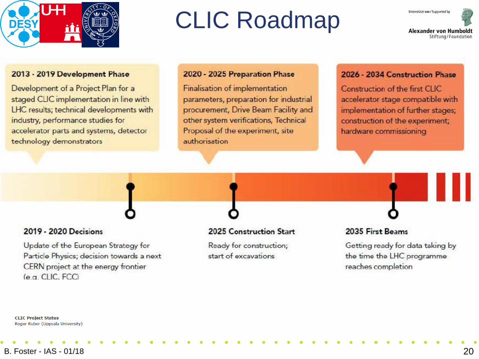
CLIC Roadmap
B. Foster - IAS - 01/18 20

LHeC (FCC-eh)
B. Foster - IAS - 01/18 21

FCC-ee
B. Foster - IAS - 01/18 22

CEPC
B. Foster - IAS - 01/18 23

CEPC
B. Foster - IAS - 01/18 24

FCC-ee optics
B. Foster - IAS - 01/18 25

FCC-ee injection
B. Foster - IAS - 01/18 26

CEPC parameters
B. Foster - IAS - 01/18 27

CEPC Luminosity
B. Foster - IAS - 01/18 28
Thermodynamic equilibration of accelerator projects

CEPC optics
B. Foster - IAS - 01/18 29
e.g. linear optics for arcs:

CEPC Linac
B. Foster - IAS - 01/18 30
BUT – Linacs are very expensive – this is essentially 1*XFEL. Injecting into Booster at such low energy is a pain!

CEPC Booster Magnets
B. Foster - IAS - 01/18 31
1) The CEPC booster is to accelerate the electron and positron beam from 10 GeV to 120 GeV. The injection energy is determined by the length and cost of the Linac.
2) The circumference of the Booster is 100 km, there are nearly 15360 dipole magnets with a length of 5 m, the min. field of the magnets is only 29 Gs whereas the max. field is 492 Gs.
3) The repetitive frequency of the booster is 0.1 Hz and the field of the dipole magnet is changing with the beam energy.
4) A high quality dipole magnet with a min. field of 29 Gs has never been developed in the world at present.

CEPC Booster Magnets
B. Foster - IAS - 01/18 32
As successful references, the low field dipole magnets of LEP and LHeC were thoroughly investigated, of which the min. field was higher than 127 Gs.
The quantity of the dipole magnets for CEPC booster is very large, the core dilution technologies in both the longitudinal and transversal directions are proposed to reduce the weight and cost of the magnets.
On the fund support of IHEP workshop, a subscale prototype dipole magnet with a length of 1m for CEPCB was manufactured.

33
RF Cavity
Plasma wakefield
20 – 40 MV/m
10 – 1000 GV/m
An alternative idea
Enables “table-top” Accelerators & promises major reduction in pp
collider length/cost
B. Foster - IAS - 01/18

CEPC PWFA Linac
B. Foster - IAS - 01/18 34
electrons
positrons
Also, John Seeman has a very smart idea to get rid of the Booster Ring using this technology. Ideas to be tested at FACET2 @ SLAC and possibly FLASHForward @ DESY
Wei Lu (Tsinghua University)

CEPC/FCCee Accelerating technology
B. Foster - IAS - 01/18 35
(PAPS=Platform for Advanced Photon Science Technology)

CEPC/FCCee Accelerating technology
B. Foster - IAS - 01/18 36
N2 doping/infusion is “flavour of the month” in the SCRF cavity world. It is however very difficult to get right.

CEPC/FCCee Machine-Detector Interface
B. Foster - IAS - 01/18 37
• Up to now, the factories have been lower energy machines (<~10 GeV) with very high beam currents (>1 A)
• However, all present and new ee machines are essentially factory designs
• eP designs have many of the ee MDI issues because of the electron beam with extra complications added in from the hadron beam (i.e. more neutrons)
• An addition, current and future ee machines are aiming for higher energies and unprecedented luminosities

CEPC/FCCee Machine-Detector Interface
B. Foster - IAS - 01/18 38
10 - 100 um
Photons that strike near the tip of a mask have a chance to scatter through the tip and then hit the central beam pipe
Photons generated from the final focus quadrupoles have to be masked away from the central beam pipe. The vertical focusing element is usually closest to the IP and easier to mask. The horizontal focusing magnet is farther back and must over-focus in order to compensate for the defocusing of the vertical focusing magnet. These photons are more difficult to mask.
Mask tip

CEPC/FCCee Synchrotron Radiation
B. Foster - IAS - 01/18 39
Multiple pieces of 20 mm thick lead placed outside of vacuum chamber To protect magnet coils from radiation damage To prevent radiation and heat entering the tunnel

FCCee Machine-Detector Interface
B. Foster - IAS - 01/18 40

CEPC Machine-Detector Interface
B. Foster - IAS - 01/18 41
Start from detector solenoid 3.0T
• Set the detector solenoid at 2T or < 2T during Z operation Higher luminosity & Lower difficulty of SC magnet & More free space nearby IP
• Dedicated lattice for Z with large emittance

CEPC Machine-Detector Interface
B. Foster - IAS - 01/18 42
Specification of Anti-Solenoid
Anti-solenoid Before QD0 Within QD0 After QD0 Central field(T) 7.2 2.8 1.8 Magnetic length(m) 1.1 2.0 1.98 Conductor (NbTi-Cu, mm) 2.5×1.5 Coil layers 16 8 4/2 Excitation current(kA) 1.0 Inductance(H) 1.2 Peak field in coil (T) 7.7 3.0 1.9 Number of sections 4 11 7 Solenoid coil inner diameter (mm) 120 Solenoid coil outer diameter (mm) 390 Total Lorentz force Fz (kN) -75 -13 88 Cryostat diameter (mm) 500

CEPC Machine-Detector Interface
B. Foster - IAS - 01/18 43

FCCpp/HE-LHC Injection
B. Foster - IAS - 01/18 44

FCCpp Magnets
B. Foster - IAS - 01/18 45

SPPC Layout
B. Foster - IAS - 01/18 46

SPPC 12T Fe-based Magnets
B. Foster - IAS - 01/18 47

Final Remarks
B. Foster - IAS - 01/18 48
This conference documents an enormous amount of progress in an very large number of projects: Super Tau-charm, Super KEKB, EIC, ILC, CLIC, HL-LHC, HE-LHC, FCCee, FCCPP, CEPC, SPPC…
Most pleasing is to note how many of the presentations and how much of the work as been done by young, energetic, people. This promises well for the future of our field.
However, I think it is clear that not all of these projects will be realised. As this work develops over the next couple of years, choices and necessary compromises will come into clearer focus.
In Europe – but also strongly affecting the rest of the world – the next CERN Strategy Process will be an important catalyst.
Last and by no means least, thanks to the organisers for the invitation to attend this highly stimulating and enjoyable conference.