Sulfur in Natural Gas /LPG GC configuration Quick Start ... · Sulfur in Natural Gas /LPG GC...
8
Sulfur in Natural Gas /LPG GC configuration Quick Start March 2013 This QuickStart document as- sumes that the user is familiar with the theory of operation of the Multiple- Gas#3 GC con- figuration. See SRI’s website for this document. Step 1: Inject natural gas ( NG ) or propane (LPG ) using the temperature pro- gram and event table shown. The goal is to determine the time between the propane and butane peaks. This time will be when we Activate Relay A to turn on the StopFlow Solenoid. Stop the run early once all the peaks are out. SRI Tech Support: 310-214-5092 Page 1 Gap between propane and butane H2S ( if present ) will appear between ethane and propane FID signal FPD signal
-
Upload
nguyenkhanh -
Category
Documents
-
view
216 -
download
0
Transcript of Sulfur in Natural Gas /LPG GC configuration Quick Start ... · Sulfur in Natural Gas /LPG GC...

Sulfur in Natural Gas /LPG GC configuration
Quick Start March 2013
This QuickStart document as-sumes that the user is familiar with the theory of operation of the Multiple-Gas#3 GC con-figuration. See SRI’s website for this document.
Step 1: Inject natural gas ( NG ) or propane (LPG ) using the temperature pro-gram and event table shown. The goal is to determine the time between the propane and butane peaks. This time will be when we Activate Relay A to turn on the StopFlow Solenoid. Stop the run early once all the peaks are out.
SRI Tech Support: 310-214-5092 Page 1
Gap between propane and butane
H2S ( if present ) will appear between ethane and propane
FID signal
FPD signal

Sulfur in Natural Gas /LPG GC configuration
Quick Start March 2013
Step 2: Modify the Event table in channel 1 to include the Re-lay A ON com-mand ( stop flow solenoid ). In this particular case, we chose 2.4 minutes since that was the time between the pro-pane and iC4 peaks on the previous analysis.
Inject the sample again and watch the chromatogram closely as it develops.
When the propane peak comes back down to the zero axis manually turn Relay A and Relay G off using the Relay/Pump Window ( click View then Relay/Pump Window ). This will allow the butane and higher peaks to elute from the capillary column. Note the time. In this case we chose 5.5 minutes.
SRI Tech Support: 310-214-5092 Page 2
This was the me Relay A
and Relay G were manually turned off
Sulfur in Natural Gas /LPG GC configuration
Quick Start March 2013
Step 3: Enter the time Re-lay A and Relay G are to turn off in the Event table for channel 1. In this case we chose 5.50 minutes be-cause this was the time in the last analysis that the propane peak had completely eluted.
Inject another sample or standard that has multiple sulfur peaks.
To save analysis time, modify the temperature program to end at an earlier time ( once all the peaks have eluted ). Some of the higher boiling sulfur peaks may take a while to elute from the column. It is not advisable to take the temperature hotter than 180C because the Teflon column ( 4 foot Porapak QS in 1/8” teflon tub-ing ) may get soft at temperatures above that. Set your temperature program to remain at 180 for as long as it takes to see all the peaks.
SRI Tech Support: 310-214-5092 Page 3
This standard contained H2S, COS and DMS in Natural Gas
Sulfur in Natural Gas /LPG GC configuration
Quick Start March 2013
SRI Tech Support: 310-214-5092 Page 4
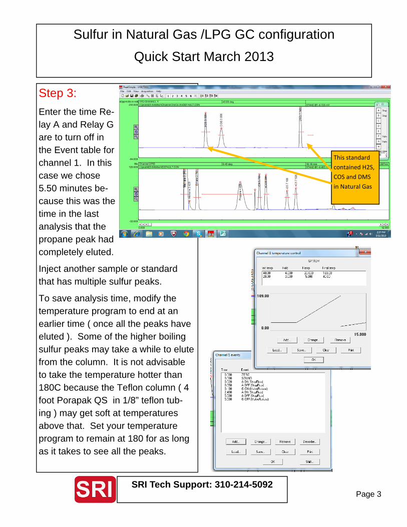
Step 4: Enter
Inject a real world sample such as propane. Most pro-pane will have an odorant molecule such as methan-ethiol added. This peak should appear after 5.50 minutes.
To make it clearer, we have overlaid the FID signal ( in red ) on top of the FPD signal ( black ). You can see the COS is just separated from the propane. This is important because if the propane elutes at the same time as the COS, it will affect the sulfur response of the FPD detector.
The methan‐ethiol peak elutes just a er nC5 and before DMS.
COS elutes just prior to pro‐pane
Sulfur in Natural Gas /LPG GC configuration
Quick Start March 2013
SRI Tech Support: 310-214-5092 Page 5
Step 4 continued:
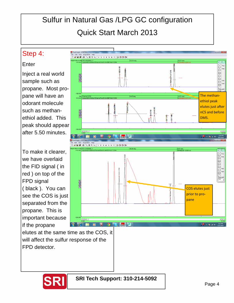
Note how the massive propane peak from the LPG ( in red ) injection shifts the retention time of both the COS and propane earlier. This is because the propane peak is so large that it overloads the column. Other peaks are not affected.
The massive propane peak also shi s earli‐er in me, and overloads the column
See the reten‐on me of
COS shi be‐tween the nat‐ural gas and LPG matrix

Sulfur in Natural Gas /LPG GC configuration
Quick Start March 2013
SRI Tech Support: 310-214-5092 Page 6
Step 5: Optimize the de-tector response and verify the detection limit.
Inject 100ppm of your sample. Here we show 100ppm H2S on medium gain with the PMT set to –400 volts.
Next 10ppm H2S. Note that the area is about 100 times less since the FPD has an exponen-tial ( not linear ) response.
100ppm H2S
10ppm H2S

Sulfur in Natural Gas /LPG GC configuration
Quick Start March 2013
SRI Tech Support: 310-214-5092 Page 7
Step 5 con-tinued:
Inject 1ppm H2S.
This peak may be small enough that it will not in-tegrate unless the Area Reject and Integration parameters are adjusted.
It is also helpful to use the Smoothing Algorithm to get rid of the high fre-quency baseline noise. The Smoothing Algo-rithm can also be invoked automat-ically at the end of the run by clicking the “Smooth First” box in the Postrun screen.
1ppm H2S
Un‐smoothed.
Peak is not in‐tegrated.
1ppm H2S
A er Smoothing and Area Reject set to 1.00
Peak IS now
integrated.
Sulfur in Natural Gas /LPG GC configuration
Quick Start March 2013
SRI Tech Support: 310-214-5092 Page 8
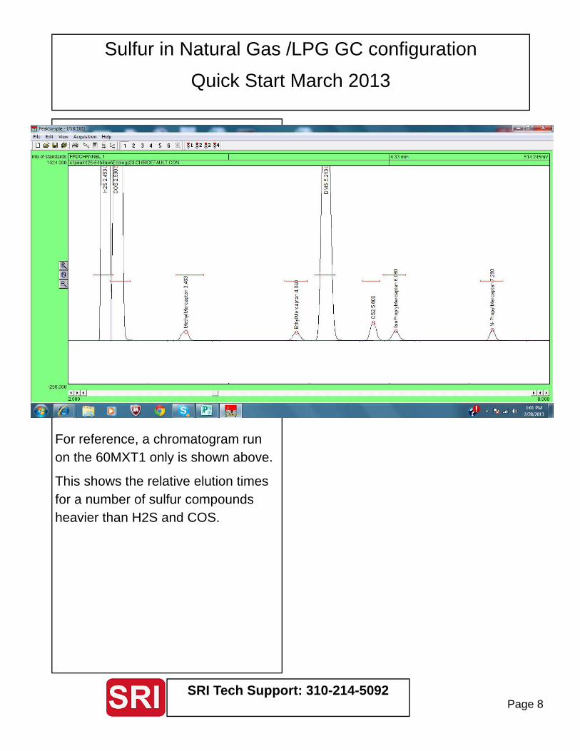
For reference, a chromatogram run on the 60MXT1 only is shown above.
This shows the relative elution times for a number of sulfur compounds heavier than H2S and COS.