Sulfone Processing Guide
24
processing UDEL ® polysulfone RADEL ® A polyethersulfone RADEL ® R polyphenylsulfone Sulfone Polymers Processing Guide
Transcript of Sulfone Processing Guide
processingUDEL®
polysulfone
RADEL® A polyethersulfone
RADEL® R polyphenylsulfone
Sulfone PolymersProcessing Guide
Contents
Introduction . . . . . . . . . . . . . . . . . . . . . . . . . . . . . . . . . . . 3
Sulfone Polymers . . . . . . . . . . . . . . . . . . . . . . . . . . . . . . 3
UDEL® polysulfone. . . . . . . . . . . . . . . . . . . . . . . . . . . 3
RADEL® A polyethersulfone . . . . . . . . . . . . . . . . . . . . 3
RADEL® R polyphenylsulfone . . . . . . . . . . . . . . . . . . . 3
ACUDEL® polyphenylsulfone blends. . . . . . . . . . . . . . 3
Resin Drying . . . . . . . . . . . . . . . . . . . . . . . . . . . . . . . . . . . 4
Rheology . . . . . . . . . . . . . . . . . . . . . . . . . . . . . . . . . . . . . . 5
Viscosity-Shear Rate . . . . . . . . . . . . . . . . . . . . . . . . . . . 5
Resin Flow Characteristics . . . . . . . . . . . . . . . . . . . . . 6
Melt Flow Index . . . . . . . . . . . . . . . . . . . . . . . . . . . 6
Spiral Flow. . . . . . . . . . . . . . . . . . . . . . . . . . . . . . . 6
Injection Molding . . . . . . . . . . . . . . . . . . . . . . . . . . . . . . . 7
Molds and Mold Design . . . . . . . . . . . . . . . . . . . . . . . . . 7
Tool steels . . . . . . . . . . . . . . . . . . . . . . . . . . . . . . . . . 7
Mold Dimensions . . . . . . . . . . . . . . . . . . . . . . . . . . . . 7
Mold Polishing . . . . . . . . . . . . . . . . . . . . . . . . . . . . . . 7
Mold Plating and Surface Treatments . . . . . . . . . . . . . 7
Tool Wear . . . . . . . . . . . . . . . . . . . . . . . . . . . . . . . . . 7
Mold Temperature Control . . . . . . . . . . . . . . . . . . . . . 7
Mold Types. . . . . . . . . . . . . . . . . . . . . . . . . . . . . . . . . 8
Two-Plate Molds . . . . . . . . . . . . . . . . . . . . . . . . . . 8
Three-Plate Molds . . . . . . . . . . . . . . . . . . . . . . . . . 8
Hot Runner Molds . . . . . . . . . . . . . . . . . . . . . . . . . 9
Cavity Layout . . . . . . . . . . . . . . . . . . . . . . . . . . . . . . . 9
Runner Systems. . . . . . . . . . . . . . . . . . . . . . . . . . . . . 9
Gating . . . . . . . . . . . . . . . . . . . . . . . . . . . . . . . . . . . 10
Sprue Gating . . . . . . . . . . . . . . . . . . . . . . . . . . . . 10
Edge Gates. . . . . . . . . . . . . . . . . . . . . . . . . . . . . . 10
Diaphragm Gates . . . . . . . . . . . . . . . . . . . . . . . . . 10
Tunnel or Submarine Gates . . . . . . . . . . . . . . . . . 10
Pin Gates . . . . . . . . . . . . . . . . . . . . . . . . . . . . . . . 11
Gate Location. . . . . . . . . . . . . . . . . . . . . . . . . . . . 11
Venting. . . . . . . . . . . . . . . . . . . . . . . . . . . . . . . . . . . 11
Part Ejection. . . . . . . . . . . . . . . . . . . . . . . . . . . . . . . 11
Draft . . . . . . . . . . . . . . . . . . . . . . . . . . . . . . . . . . 11
Ejector Pins and/or Stripper Plates . . . . . . . . . . . . 12
Injection Molding Equipment. . . . . . . . . . . . . . . . . . . . . 12
Controls . . . . . . . . . . . . . . . . . . . . . . . . . . . . . . . . . . 12
Clamp . . . . . . . . . . . . . . . . . . . . . . . . . . . . . . . . . . . 12
Barrel Capacity. . . . . . . . . . . . . . . . . . . . . . . . . . . . . 12
Press Maintenance. . . . . . . . . . . . . . . . . . . . . . . . . . 12
Screw Design. . . . . . . . . . . . . . . . . . . . . . . . . . . . . . 12
Screw Tips and Check Valves . . . . . . . . . . . . . . . . . . 12
Nozzles . . . . . . . . . . . . . . . . . . . . . . . . . . . . . . . . . . 12
Molding Process. . . . . . . . . . . . . . . . . . . . . . . . . . . . 13
Polymer Injection or Mold Filling . . . . . . . . . . . . . . . . 13
Packing and Holding. . . . . . . . . . . . . . . . . . . . . . . . . 13
Cooling. . . . . . . . . . . . . . . . . . . . . . . . . . . . . . . . . . . 14
Machine Settings . . . . . . . . . . . . . . . . . . . . . . . . . . . . . 14
Barrel Temperatures. . . . . . . . . . . . . . . . . . . . . . . . . 14
Mold Temperature . . . . . . . . . . . . . . . . . . . . . . . . . . 14
Residence Time in the Barrel . . . . . . . . . . . . . . . . . . 15
Injection Rate . . . . . . . . . . . . . . . . . . . . . . . . . . . . . . 15
Back Pressure . . . . . . . . . . . . . . . . . . . . . . . . . . . . . 15
Screw Speed . . . . . . . . . . . . . . . . . . . . . . . . . . . . . . 15
Shrinkage. . . . . . . . . . . . . . . . . . . . . . . . . . . . . . . . . 15
Regrind . . . . . . . . . . . . . . . . . . . . . . . . . . . . . . . . . . . . 15
Measuring Residual Stress . . . . . . . . . . . . . . . . . . . . . . 16
Troubleshooting Guide . . . . . . . . . . . . . . . . . . . . . . . . . . 17
Extrusion. . . . . . . . . . . . . . . . . . . . . . . . . . . . . . . . . . . . . 18
Predrying . . . . . . . . . . . . . . . . . . . . . . . . . . . . . . . . . . . 18
Extrusion Temperatures . . . . . . . . . . . . . . . . . . . . . . . . 18
Screw Design Recommendations . . . . . . . . . . . . . . . 18
Die Design . . . . . . . . . . . . . . . . . . . . . . . . . . . . . . . . . . 18
Extruded Product Types . . . . . . . . . . . . . . . . . . . . . . 18
Wire . . . . . . . . . . . . . . . . . . . . . . . . . . . . . . . . . . . 18
Film . . . . . . . . . . . . . . . . . . . . . . . . . . . . . . . . . . . 19
Sheet . . . . . . . . . . . . . . . . . . . . . . . . . . . . . . . . . . 19
Piping and Tubing. . . . . . . . . . . . . . . . . . . . . . . . . 19
Start-Up, Shut-Down, and Purging . . . . . . . . . . . . . . . . 20
Start-Up Procedure. . . . . . . . . . . . . . . . . . . . . . . . . . 20
Shut-Down Procedure . . . . . . . . . . . . . . . . . . . . . . . 20
Purging . . . . . . . . . . . . . . . . . . . . . . . . . . . . . . . . . . 20
Thermoforming. . . . . . . . . . . . . . . . . . . . . . . . . . . . . . . 21
Introduction
Sulfone PolymersSolvay Advanced Polymers has the broadest range ofhigh-performance sulfone polymers offered by any com-pany in the world. These high-temperature amorphousthermoplastics are inherently transparent and are notedfor their strength, rigidity, and outstanding dimensionalstability. Continuous use in air or in steam at elevatedtemperature does not cloud, craze, or otherwise destroythe material’s transparency.
The natural color of sulfone resins is a transparent amber,ranging from light to medium. Solvay Advanced Polymers’new product technology has significantly lowered thecolor of these materials, approaching water white forspecific grades of polysulfone. Sulfone polymers are alsoavailable in opaque colors and in mineral-filled and glass-reinforced compounds, which provide improvedstrength, stiffness, and thermal stability.
Sulfone polymers can be processed following standardmethods for injection molding, extrusion, and blow mold-ing. Shapes can be machined for prototype evaluations;film and sheet can be thermoformed on conventionalequipment. Plus, you can do most post-fabrication opera-tions such as ultrasonic welding, adhesive bonding, andlaser marking as well as heat staking, threading, andmachining. Sulfone polymers can also be solution pro-cessed to make coatings and membranes.
UDEL® polysulfoneThis tough, rigid, high-strength thermoplastic has a heatdeflection temperature of 174°C (345°F) and maintainsits properties over a wide temperature range. UDELpolysulfone excels in many fluid-handling applicationsand has over 10 years of success replacing brass in pres-surized hot water plumbing applications.
RADEL® A polyethersulfoneThis resin combines good chemical resistance with a highheat deflection temperature of 204°C (400°F), making it agood fit for baby bottles and other food service applica-tions. Because the material is inherently flame retardant,
it is also used for electronic components and testingdevices.
RADEL® R polyphenylsulfoneFor severe service applications requiring repeated steril-ization or uncompromising toughness, RADEL Rpolyphenylsulfone really stands out. With a high heatdeflection temperature of 207°C (405°F), it can withstandcontinuous exposure to heat and still absorb tremendousimpact without cracking or breaking. It is inherently flameretardant and offers exceptional resistance to bases andother chemicals.
ACUDEL® polyphenylsulfone blendsThese proprietary blends open the door to morecost-sensitive applications that require toughness andchemical resistance as well as hydrolytic and dimen-sional stability.
Processing Sulfone Polymers 3
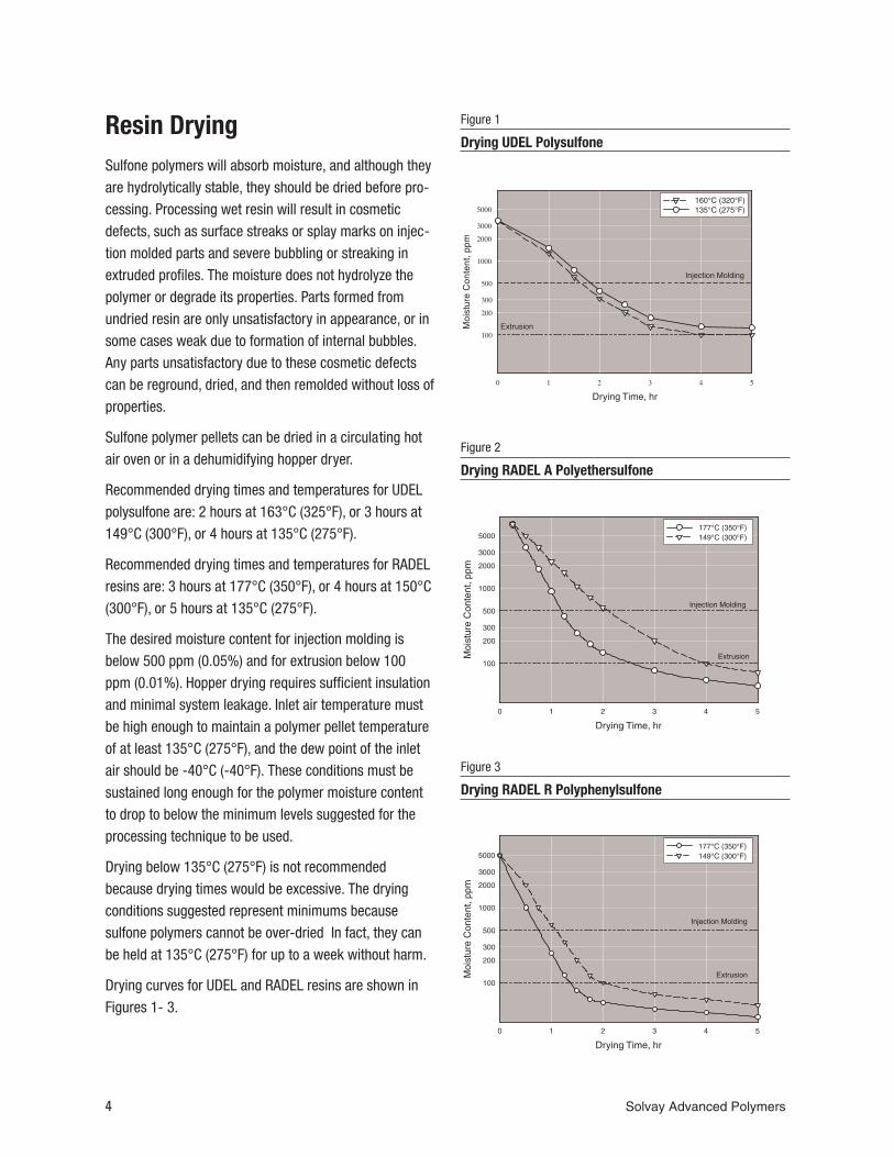
Resin DryingSulfone polymers will absorb moisture, and although theyare hydrolytically stable, they should be dried before pro-cessing. Processing wet resin will result in cosmeticdefects, such as surface streaks or splay marks on injec-tion molded parts and severe bubbling or streaking inextruded profiles. The moisture does not hydrolyze thepolymer or degrade its properties. Parts formed fromundried resin are only unsatisfactory in appearance, or insome cases weak due to formation of internal bubbles.Any parts unsatisfactory due to these cosmetic defectscan be reground, dried, and then remolded without loss ofproperties.
Sulfone polymer pellets can be dried in a circulating hotair oven or in a dehumidifying hopper dryer.
Recommended drying times and temperatures for UDELpolysulfone are: 2 hours at 163°C (325°F), or 3 hours at149°C (300°F), or 4 hours at 135°C (275°F).
Recommended drying times and temperatures for RADELresins are: 3 hours at 177°C (350°F), or 4 hours at 150°C(300°F), or 5 hours at 135°C (275°F).
The desired moisture content for injection molding isbelow 500 ppm (0.05%) and for extrusion below 100ppm (0.01%). Hopper drying requires sufficient insulationand minimal system leakage. Inlet air temperature mustbe high enough to maintain a polymer pellet temperatureof at least 135°C (275°F), and the dew point of the inletair should be -40°C (-40°F). These conditions must besustained long enough for the polymer moisture contentto drop to below the minimum levels suggested for theprocessing technique to be used.
Drying below 135°C (275°F) is not recommendedbecause drying times would be excessive. The dryingconditions suggested represent minimums becausesulfone polymers cannot be over-dried In fact, they canbe held at 135°C (275°F) for up to a week without harm.
Drying curves for UDEL and RADEL resins are shown inFigures 1- 3.
4 Solvay Advanced Polymers
Figure 1
Drying UDEL Polysulfone
Figure 2
Drying RADEL A Polyethersulfone
Figure 3
Drying RADEL R Polyphenylsulfone
Resin drying time may have to be increased in highlyhumid weather. An air-tight oven equipped with a dehu-midifying unit in which the air is recirculated over a dry-ing bed is recommended as the most uniform and effi-cient drying method. Dried resin should be placed insealed containers to maintain dryness.
In continuous molding and extrusion operations, it is rec-ommended that a dehumidifying hopper dryer beattached directly to the processing equipment. These effi-cient dryers permit continuous processing operations.The dryer should be sized such that residence time of theresin in the dryer is long enough to effectively dry theresin to the desired moisture content at maximum pro-duction rate.
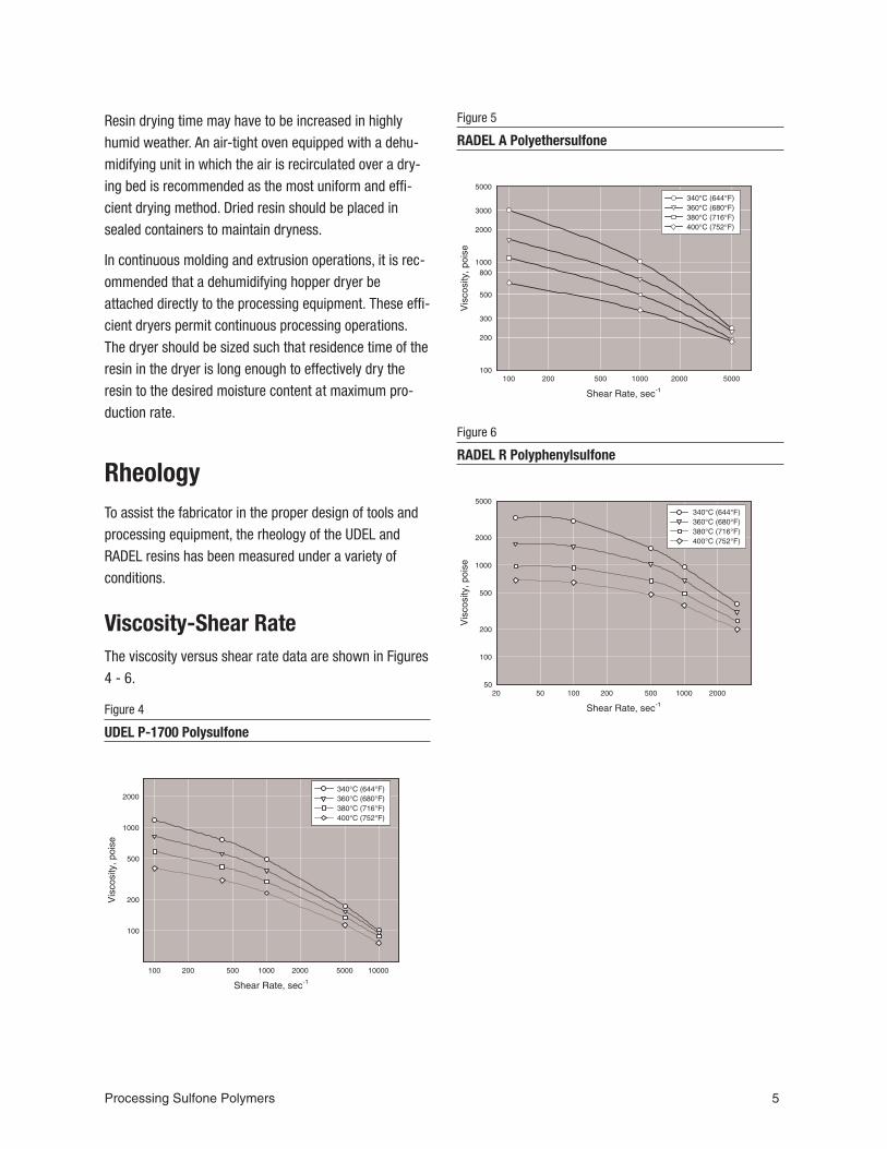
RheologyTo assist the fabricator in the proper design of tools andprocessing equipment, the rheology of the UDEL andRADEL resins has been measured under a variety ofconditions.
Viscosity-Shear RateThe viscosity versus shear rate data are shown in Figures4 - 6.
Processing Sulfone Polymers 5
Figure 4
UDEL P-1700 Polysulfone
Figure 5
RADEL A Polyethersulfone
Figure 6
RADEL R Polyphenylsulfone
Resin Flow Characteristics
Melt Flow IndexAnother common method for quantifying melt flow isdetailed in the ASTM test method D 1238, Melt Flow ratesof Thermoplastics by Extrusion Plastometer. The valuesobtained by this method must specify the temperatureand load used for the measurement. Table 1 gives thetypical flow rates for selected sulfone resin grades.
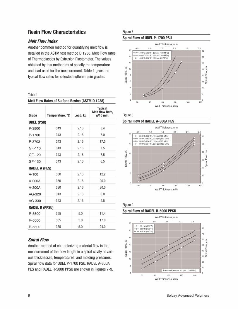
Spiral FlowAnother method of characterizing material flow is themeasurement of the flow length in a spiral cavity at vari-ous thicknesses, temperatures, and molding pressures.Spiral flow data for UDEL P-1700 PSU, RADEL A-300APES and RADEL R-5000 PPSU are shown in Figures 7-9.
6 Solvay Advanced Polymers
Figure 7
Spiral Flow of UDEL P-1700 PSU
Figure 8
Spiral Flow of RADEL A-300A PES
Figure 9
Spiral Flow of RADEL R-5000 PPSU
Grade Temperature, °C Load, kg
TypicalMelt flow Rate,
g/10 min.
UDEL (PSU)
P-3500 343 2.16 3.4
P-1700 343 2.16 7.0
P-3703 343 2.16 17.5
GF-110 343 2.16 7.5
GF-120 343 2.16 7.5
GF-130 343 2.16 6.5
RADEL A (PES)
A-100 380 2.16 12.2
A-200A 380 2.16 20.0
A-300A 380 2.16 30.0
AG-320 343 2.16 6.0
AG-330 343 2.16 4.5
RADEL R (PPSU)
R-5500 365 5.0 11.4
R-5000 365 5.0 17.0
R-5800 365 5.0 24.0
Table 1
Melt Flow Rates of Sulfone Resins (ASTM D 1238)
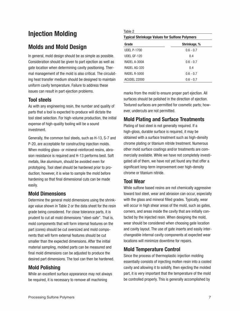
Injection Molding
Molds and Mold DesignIn general, mold design should be as simple as possible.Consideration should be given to part ejection as well asgate location when determining cavity positioning. Ther-mal management of the mold is also critical. The circulat-ing heat transfer medium should be designed to maintainuniform cavity temperature. Failure to address theseissues can result in part ejection problems.
Tool steelsAs with any engineering resin, the number and quality ofparts that a tool is expected to produce will dictate thetool steel selection. For high-volume production, the initialexpense of high-quality tooling will be a soundinvestment.
Generally, the common tool steels, such as H-13, S-7 andP-20, are acceptable for constructing injection molds.When molding glass- or mineral-reinforced resins, abra-sion resistance is required and H-13 performs best. Softmetals, like aluminum, should be avoided even forprototyping. Tool steel should be hardened prior to pro-duction; however, it is wise to sample the mold beforehardening so that final dimensional cuts can be madeeasily.
Mold DimensionsDetermine the general mold dimensions using the shrink-age value shown in Table 2 or the data sheet for the resingrade being considered. For close tolerance parts, it isprudent to cut all mold dimensions “steel-safe”. That is,mold components that will form internal features on thepart (cores) should be cut oversized and mold compo-nents that will form external features should be cutsmaller than the expected dimensions. After the initialmaterial sampling, molded parts can be measured andfinal mold dimensions can be adjusted to produce thedesired part dimensions. The tool can then be hardened.
Mold PolishingWhile an excellent surface appearance may not alwaysbe required, it is necessary to remove all machining
marks from the mold to ensure proper part ejection. Allsurfaces should be polished in the direction of ejection.Textured surfaces are permitted for cosmetic parts; how-ever, undercuts are not permitted.
Mold Plating and Surface TreatmentsPlating of tool steel is not generally required. If ahigh-gloss, durable surface is required, it may beobtained with a surface treatment such as high-densitychrome plating or titanium nitride treatment. Numerousother mold surface coatings and/or treatments are com-mercially available. While we have not completely investi-gated all of them, we have not yet found any that offer asignificant long-term improvement over high-densitychrome or titanium nitride.
Tool WearWhile sulfone based resins are not chemically aggressivetoward tool steel, wear and abrasion can occur, especiallywith the glass and mineral filled grades. Typically, wearwill occur in high shear areas of the mold, such as gates,corners, and areas inside the cavity that are initially con-tacted by the injected resin. When designing the mold,wear should be considered when choosing gate locationand cavity layout. The use of gate inserts and easily inter-changeable internal cavity components at expected wearlocations will minimize downtime for repairs.
Mold Temperature ControlSince the process of thermoplastic injection moldingessentially consists of injecting molten resin into a cooledcavity and allowing it to solidify, then ejecting the moldedpart, it is very important that the temperature of the moldbe controlled properly. This is generally accomplished by
Processing Sulfone Polymers 7
Grade Shrinkage, %
UDEL P-1700 0.6 - 0.7
UDEL GF-120 0.4
RADEL A-300A 0.6 - 0.7
RADEL AG-320 0.4
RADEL R-5000 0.6 - 0.7
ACUDEL 22000 0.6 - 0.7
Table 2
Typical Shrinkage Values for Sulfone Polymers
circulating a heat transfer medium through channels inthe mold. Sulfone polymers require mold temperaturesgreater than 138°C (280°F) so a heat transfer oil isrequired.
Electric cartridge heaters should not be used. Althoughthey have the capability to heat the mold, they cannotremove heat from the mold. Since the polymer beinginjected into the mold is considerably hotter than the cav-ity, the excess heat needs to be removed. This is espe-cially true in thermally isolated areas such as core pinswhere heat may build up and cause ejection problems.Thermally conductive copper-beryllium pins may beinserted into these areas to facilitate heat transfer.
The heat transfer channels in the mold should be locatedequidistant from each cavity and the flow designed sothat each cavity is exposed to the same amount and tem-perature of fluid. The flow pattern past the cavities shouldbe designed to be concurrent rather than sequential. Theinternal lines carrying the heat transfer fluid should besized, within the limits of the available flow rate, to createturbulent flow to maximize heat transfer.
Mold TypesThere are several types of molds that can be used tomold sulfone resins. These include two-plate, three-plateand hot-runner systems. All of these can contain manualor hydraulic slides and other required features.
Two-Plate MoldsTwo-plate, or A-B molds are the simplest and most com-mon of all mold types. They use a stationary A side and amovable B side. The molten resin is injected through thesprue in the A side, along a runner system on the partingline into the mold cavity or cavities, usually cut into the Bside.
Because the ejector system is generally designed to ejectthe molded part from the movable or B side, it is neces-sary that the part, the sprue, and the runner systemremain on the B side when the mold opens. To ensurethat this occurs, it is common practice to cut the coldslug well, the runner system, and the majority of the cav-ity in the B side.
The cold slug well, normally cut into the B side oppositethe sprue, has two functions. First, it collects the leadingedge of the injected shot, which usually contains a coldslug of resin from the nozzle tip, and prevents that mate-rial from entering the mold cavity. Second, by virtue of aslight undercut, the cold slug well will pull the sprue outof the A side as the mold opens. Placing an ejector pin inthe B side at the cold slug well will eject the sprue.
To ensure that the molded part itself stays in the movableside on mold opening, it is common practice to have themajority of the part formed in that side. Detail in the sta-tionary side should be kept to a minimum. When it is nec-essary to have significant detail in the A side, plans forpositive ejection out of the A side, such as aspring-loaded ejector system, are advisable.
Three-Plate MoldsThree plate molds are a modification of the two-platesystem in which a center plate is added between themovable and stationary plates. This center plate isolatesthe sprue and runner system from the parts. The runnersystem is formed between the stationary and the centerplates and the molded parts are formed between the cen-ter and movable plates. When the mold opens, the partsremain and are ejected from the movable plate. The run-ner system and sprue, however, are broken from themolded parts and remain between the center and station-ary plates. A spring loaded ejector system in the centerplate ejects the runner.
The runner system is usually cut into the center plate ofthe mold as well. Ejector pins in the runner system whichare partially below the surface, known as sucker pinsensure that the runner stays in the center plate. Thesesucker pins can contain slight undercuts.
There are several aspects of this system that make itmore attractive than the two-plate system. First, degatingis accomplished during the part ejection process, not as asecondary operation. Second, there is far greater freedomin selecting the number and the location of the gates bythe placement of the gate drops through the center plate.Larger parts may be gated at several locations for ease offilling.
8 Solvay Advanced Polymers
Hot Runner MoldsIn hot runner molds, the plate containing the sprue andrunners is replaced with an electrically heated manifoldcontaining channels that carry the molten resin from thebarrel to the cavities. The resin in the manifold remains inthe molten state. During injection, the molten resin flowsinto the cavities on the B side directly from the manifolddrops, where it is cooled and the part is ejected. Hot run-ner molds are extremely popular due to their materialefficiency. Since no sprue and runner are molded, all ofthe resin is in the part.
Hot runner molds are often provided as a turnkey system;however, certain aspects of the design are important forsuccessful operation with sulfone resins. The hot runnermanifold channels should be free-flowing without sharpcorners or flow impediments. Any stagnant resin will tendto thermally degrade due to excessive residence time andcontaminate the melt and the parts.
The temperature control of a hot runner mold is critical.Excessive residence time in the manifold should beavoided as it can result in material degradation. Separatetemperature controllers for each drop on the manifoldmust be used. The controlling thermocouple for each heatsource in the manifold should be close to the resin andbetween the heat source and the resin. In addition theflow path must be unrestricted with no internal mecha-nisms or channels. Flow restrictions will increase theshear on the material and may result in discoloration anddegradation of the resin.
Cavity LayoutIn any multi-cavity mold, a balanced cavity arrangementis critical to molding quality parts. This means that all ofthe cavities must contain the same volume and fill at thesame time. An unbalanced mold will over-pack somecavities while others are underpacked. A balanced moldfills all cavities at the same rate with the same pressure,ensuring uniform parts. Usually, this is accomplished byplacing the cavities equidistant from the sprue with iden-tically sized runners. The flow path should have the samelength to each cavity.
Family molds are sometimes constructed to mold two ormore different shaped parts in a single mold. This type ofmold is often impossible to balance and should beavoided. When economics require that different cavitiesbe placed in a single mold base, the runner systemshould be balanced to each cavity and be equipped withcavity shutoffs. If acceptable parts cannot be moldedtogether, cavity shutoffs allow each part to be moldedindividually.
Runner SystemsThe purpose of the runner system is to provide a channelconnecting the sprue and the cavity. To avoid wasting thematerial in the sprue and runner system, the sprue andrunner are generally ground and reused. Typically mixing25% ground sprues and runners with 75% virgin resin isallowed. Therefore, the most material-efficient molddesign will be achieved when the sprue and runnerweight is no more than 25% of the total shot weight.
Reducing the weight of the runner can be accomplishedby minimizing both the length of the runner and the run-ner surface-to-volume ratio. A full round runner has thelowest surface-to-volume ratio. It is the most efficientrunner, but is difficult to fabricate. A trapezoidal runnerwith a 10% slope increases the weight of the runner sys-tem by about 25%, but is considerably easier to machine.The size of the runner will depend on the length of theflow path and the grade of resin being used. In all cases,the thickness of the runner should be larger than thethickest section of the part to ensure that the runner doesnot freeze off before the part is fully densified.
When a runner splits to fill two or more cavities, the totalarea of the secondary runners should be no greater thanthe area of the primary runner. This will ensure that thevelocity of the melt front is not decreased.
Cold slug wells should be used at every turn in the runnersystem as well as at the base of the sprue. These wellswill serve to remove the leading edge of the advancingmelt and prevent the introduction of cold material into thecavity.
Since the material in the runner system is usuallyre-used, the runner system should be well-vented to
Processing Sulfone Polymers 9
prevent burn marks. Venting the runner will also allow thegas in the runner to exit out of the runner rather thanthrough the part cavities.
Keeping the runner system on the proper plate duringmold opening can be accomplished with sprue pullersand sucker pins that provide slight undercuts. Generousejector pins on the runner system will ensure positiveejection from the mold.
GatingAll conventional gating types are suitable for processingsulfone resins, including hot runner systems. The consid-erations for selecting a gating method should includegate location for optimal densification, gate removalmethod, generation and use of regrind, and cosmeticrequirements.
The dimensions of a gate depend on several factors,including the size of the part, its thickness, the type ofgate being used, and the grade of resin. In general, thesmallest gate dimension should be at least 50% of thewall thickness at the point being gated into to ensureoptimum densification. If the gates are too small, partsmay be underpacked, shrink erratically, have internalporosity or sink marks, and have poor mechanicalperformance.
Sulfone resins have a high viscosity and do not shear thinduring the injection process. Therefore, it is important toradius sharp edges in the gate area, wherever possible.
Sprue GatingSprue (direct) gating is most often used with hot runnersystems and is often used on prototype molds as well.This method places the mold cavity directly in line withthe sprue or under the hot runner drop. The major advan-tages of this method include system simplicity and mini-mized runner volume and flow length. The disadvantagesof sprue gating include the potential for cold slugs to bevisible on the part and the need to remove the sprue orhot runner vestige. This generally involves apost-machining operation or a manual operation by theoperator at the press.
Edge GatesEdge gates are by far the most common gate type. Thesegates are used with a conventional sprue and runner sys-tem. The runner introduces the resin to the mold cavityalong the parting line. Cold slug wells are placed in therunner system to keep cold slugs out of the parts. Anundercut is generally placed in the movable side of themold to act as a sprue puller. Rectangular edge gatesshould be 1.5 to 2 times as wide as they are deep andproportional to the part thickness.
Advantages of edge gates include ease of fabrication,modification, maintenance, and trouble-free operation.Cold slug wells eliminate cold slugs in parts. The disad-vantage of this gating method is the generation of scrap,some of which may be ground and reused. Gate insertsare strongly recommended for ease of gate replacementif excessive wear occurs.
Diaphragm GatesDiaphragm gating is used almost exclusively for moldingcircular parts without knit lines. A high degree of flatnesscan also be attained with this method when using afiber-reinforced grade that may be prone to warpagewhen using other gate types. Similar to sprue gating, amachining operation will be required to remove the gate.
Tunnel or Submarine GatesTunnel or submarine gating is another popular methodbecause it is self-degating. Tunnel gates employ a
10 Solvay Advanced Polymers
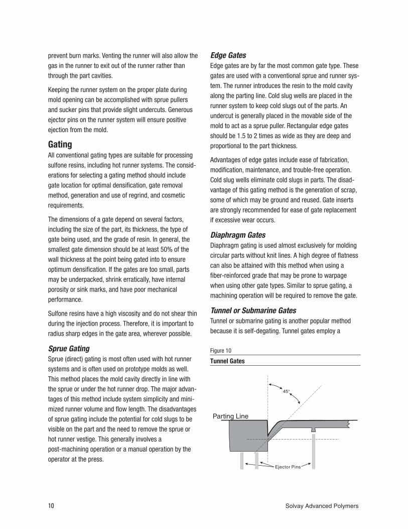
Figure 10
Tunnel Gates
conventional parting line runner system similar to a stan-dard edge gate. In close proximity to the mold cavity,however, the runner tunnels beneath the parting line andgates into the part below the mold parting surfaces, asillustrated in Figure 10. Upon ejection, the molded partand runner/gate are separated by the tool steel itself. Theangle of the drop is critical in ensuring that the runnerwill eject properly and not become stuck in the mold.Unfilled sulfone resins typically work well with an angle of45 degrees perpendicular to the parting line of the mold.Glass filled grades with a higher modulus may require amore-severe drop angle, closer to 30 degrees.
The main advantage of tunnel gates is the automaticdegating feature. A potential disadvantage is the possibil-ity of an irregular gate vestige and high shear. Gateinserts are strongly recommended for use with tunnelgates.
Tunnel gates should be a minimum 0.040" (1 mm) on theminor axis, increasing in size for larger parts.
Pin GatesThree plate molds should use proportionally sized gates,but no less than 0.040" (1 mm) in diameter for smallparts and no more than 0.125" (3.2 mm) in diameter forlarge parts. Very large gates used with three plate moldsmay cause degating problems.
Gate LocationGates should always be located in the thickest section ofthe part to allow flow from thick to thin sections. Cos-metic considerations may dictate gate locations; how-ever, it is inadvisable to flow through a thin section to athicker section. Other factors that may influence gatelocation include knit line location, flatness requirements,and the number of gates required to fill the part.
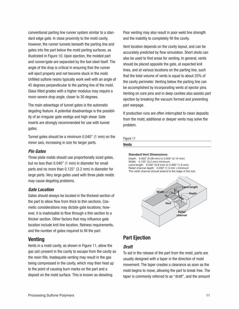
VentingVents in a mold cavity, as shown in Figure 11, allow thegas (air) present in the cavity to escape from the cavity asthe resin fills. Inadequate venting may result in the gasbeing compressed in the cavity, which may then heat upto the point of causing burn marks on the part and adeposit on the mold surface. This is known as dieseling.
Poor venting may also result in poor weld line strengthand the inability to completely fill the cavity.
Vent location depends on the cavity layout, and can beaccurately predicted by flow simulation. Short shots canalso be used to find areas for venting. In general, ventsshould be placed opposite the gate, at expected knitlines, and at various locations on the parting line, suchthat the total volume of vents is equal to about 25% ofthe cavity perimeter. Venting below the parting line canbe accomplished by incorporating vents at ejector pins.Venting on core pins and in deep cavities also assists partejection by breaking the vacuum formed and preventingpart warpage.
If production runs are often interrupted to clean depositsfrom the mold, additional or deeper vents may solve theproblem.
Part Ejection
DraftTo aid in the release of the part from the mold, parts areusually designed with a taper in the direction of moldmovement. The taper creates a clearance as soon as themold begins to move, allowing the part to break free. Thetaper is commonly referred to as “draft”, and the amount
Processing Sulfone Polymers 11
Figure 11
Vents
of taper referred to as “draft angle”. As a rule, the drafton injection molds for sulfone resins should be 1 to 2°.
Ejector Pins and/or Stripper PlatesThe area of ejectors or stripper plates should be as largeas possible. Ejector pins must not be too thin, or they maypress into the parts and deform the parts during rapidcycling or at high mold temperatures.
Injection Molding EquipmentControlsThe injection molding machine should be capable of con-trolling the injection portion of the process by velocity andscrew position. Most machines made after 1980 have thiscapability. Older machines can be retrofitted with lineartransducers and electronic controllers. It is desirable ifthe press controls include the capability to monitor andallow alarms to be set for the following process variables:injection time, cushion, and hydraulic pressure at transferposition.
ClampChoose a press that provides a clamp pressure of at least4 tons per square inch (8 kpsi, 545 bar, or 55 MPa) ofprojected part area.
Barrel CapacityThe barrel capacity should be between 1.5 and 3.3 timesthe shot size. A press of this size minimizes residence
time in the barrel, because each shot will use 30 to 60%of the barrel capacity.
Press Maintenanceinjection molding machines need to be properly main-tained. The barrel to screw clearance should be moni-tored regularly to make sure it is still conforms to themanufacturers specification. The check ring should rou-tinely be checked for excessive wear.
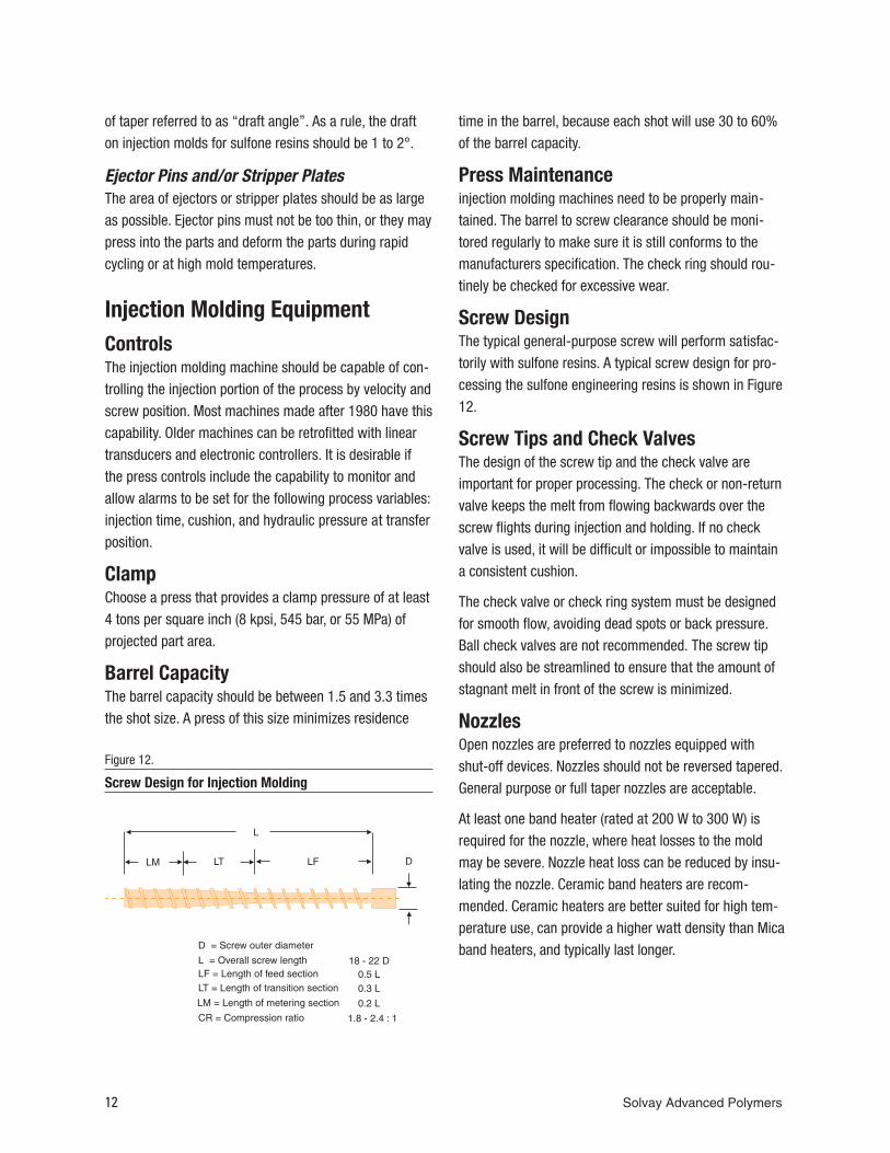
Screw DesignThe typical general-purpose screw will perform satisfac-torily with sulfone resins. A typical screw design for pro-cessing the sulfone engineering resins is shown in Figure12.
Screw Tips and Check ValvesThe design of the screw tip and the check valve areimportant for proper processing. The check or non-returnvalve keeps the melt from flowing backwards over thescrew flights during injection and holding. If no checkvalve is used, it will be difficult or impossible to maintaina consistent cushion.
The check valve or check ring system must be designedfor smooth flow, avoiding dead spots or back pressure.Ball check valves are not recommended. The screw tipshould also be streamlined to ensure that the amount ofstagnant melt in front of the screw is minimized.
NozzlesOpen nozzles are preferred to nozzles equipped withshut-off devices. Nozzles should not be reversed tapered.General purpose or full taper nozzles are acceptable.
At least one band heater (rated at 200 W to 300 W) isrequired for the nozzle, where heat losses to the moldmay be severe. Nozzle heat loss can be reduced by insu-lating the nozzle. Ceramic band heaters are recom-mended. Ceramic heaters are better suited for high tem-perature use, can provide a higher watt density than Micaband heaters, and typically last longer.
12 Solvay Advanced Polymers
Figure 12.
Screw Design for Injection Molding
Molding ProcessFor this discussion, the molding process can be envi-sioned as three distinct steps:
• polymer injection or mold filling,• packing and holding or part densification,• cooling and screw recovery.
Polymer Injection or Mold FillingThe mold-filling step is the portion of the cycle at highinjection pressure; it ends when the pressure is reducedto the lower hold pressure. This step of the process canbe controlled using a variety of process control methods.
These include controlling the time at a constant injectionpressure, controlling the injection rate until the screwposition reaches a set point, transfering to hold pressureon cavity pressure, or transfering to hold pressure at peakhydraulic pressure.
The most common method is to control the injection rateor velocity, and to switch to hold pressure at a set screwposition or transition point. The advantage of this methodis that a controlled volume of resin is being delivered tothe cavity at a specified rate. Generally, medium to slowinjection rates are recommended.
To use this method, the proper screw position for switch-ing from injection pressure to hold pressure must bedetermined. This position should be such that the part isabout 95% filled; the remainder of the part should befilled and packed out with hold pressure. This methodshould allow any remaining gas in the tool to be ventedwithout burning. An efficient method for determining thecorrect screw position for the transition to hold pressureis as follows:
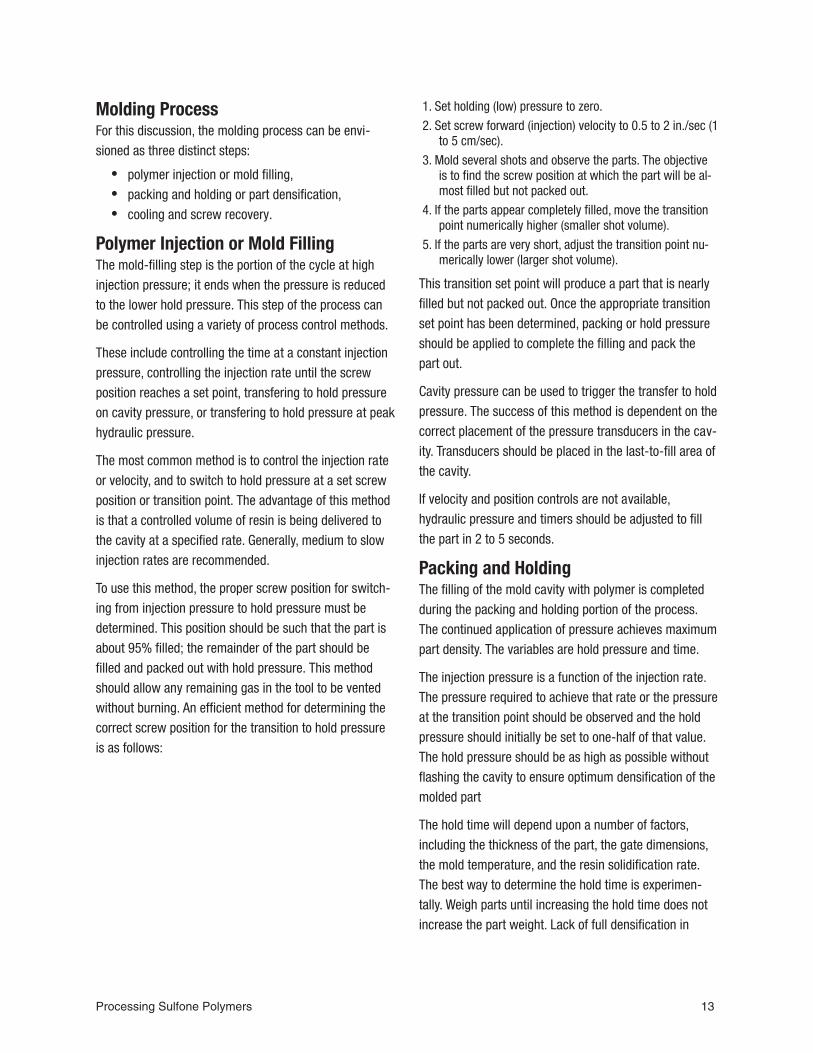
1. Set holding (low) pressure to zero.
2. Set screw forward (injection) velocity to 0.5 to 2 in./sec (1to 5 cm/sec).
3. Mold several shots and observe the parts. The objectiveis to find the screw position at which the part will be al-most filled but not packed out.
4. If the parts appear completely filled, move the transitionpoint numerically higher (smaller shot volume).
5. If the parts are very short, adjust the transition point nu-merically lower (larger shot volume).
This transition set point will produce a part that is nearlyfilled but not packed out. Once the appropriate transitionset point has been determined, packing or hold pressureshould be applied to complete the filling and pack thepart out.
Cavity pressure can be used to trigger the transfer to holdpressure. The success of this method is dependent on thecorrect placement of the pressure transducers in the cav-ity. Transducers should be placed in the last-to-fill area ofthe cavity.
If velocity and position controls are not available,hydraulic pressure and timers should be adjusted to fillthe part in 2 to 5 seconds.
Packing and HoldingThe filling of the mold cavity with polymer is completedduring the packing and holding portion of the process.The continued application of pressure achieves maximumpart density. The variables are hold pressure and time.
The injection pressure is a function of the injection rate.The pressure required to achieve that rate or the pressureat the transition point should be observed and the holdpressure should initially be set to one-half of that value.The hold pressure should be as high as possible withoutflashing the cavity to ensure optimum densification of themolded part
The hold time will depend upon a number of factors,including the thickness of the part, the gate dimensions,the mold temperature, and the resin solidification rate.The best way to determine the hold time is experimen-tally. Weigh parts until increasing the hold time does notincrease the part weight. Lack of full densification in
Processing Sulfone Polymers 13
molded parts may result in performance problems includ-ing warpage, uneven shrinkage, and sinks or voids.
CoolingDuring the cooling step, the part becomes stiff and strongenough to be ejected without warpage and/or deforma-tion from the ejector pins. Simultaneously, the screwrotates, plasticizing material for the next cycle. The speedat which the screw rotates should be between 60 and100 rpm, with just enough back pressure to ensure a uni-form shot size.
If long cooling times are used, the polymer’s residencetime in the barrel can become excessive, resulting inpolymer degradation. A screw delay (added time intervalbetween the end of Pack/Hold and screw recovery) canhelp to minimize degradation.
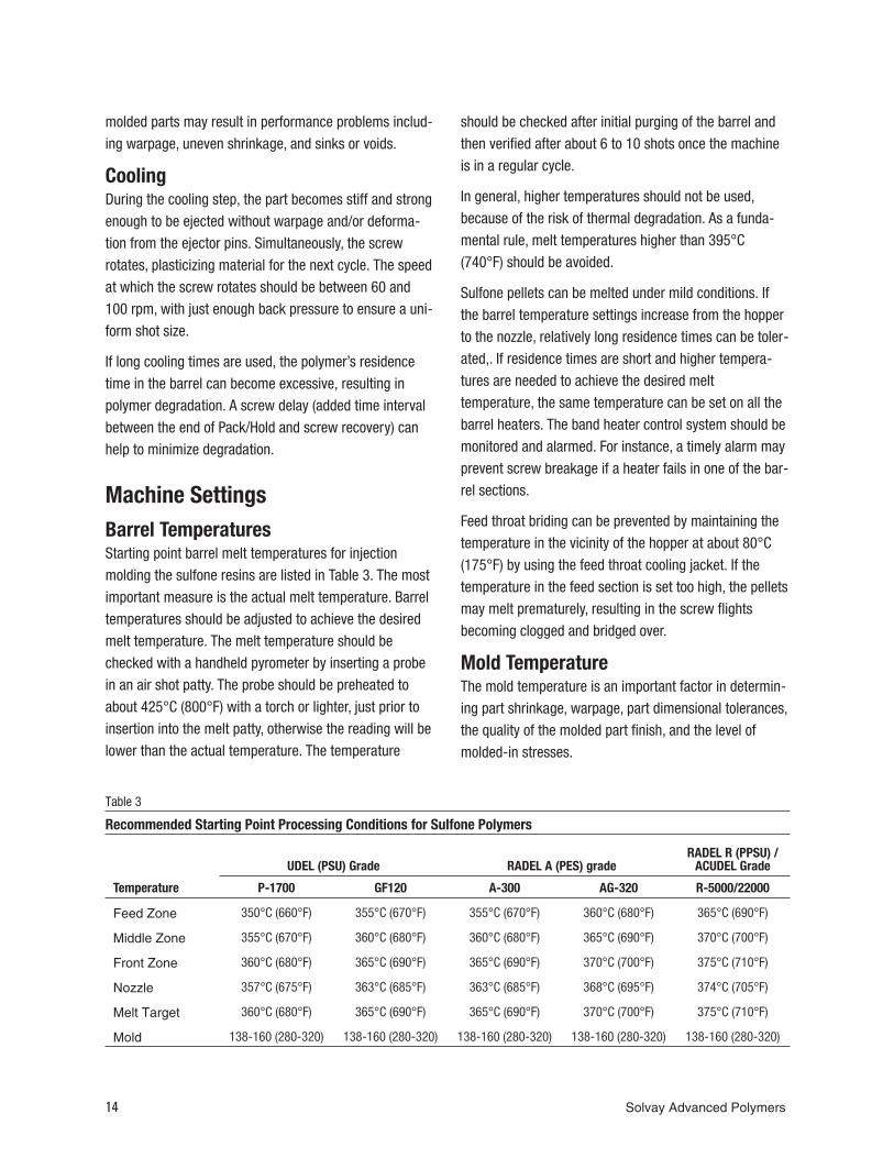
Machine SettingsBarrel TemperaturesStarting point barrel melt temperatures for injectionmolding the sulfone resins are listed in Table 3. The mostimportant measure is the actual melt temperature. Barreltemperatures should be adjusted to achieve the desiredmelt temperature. The melt temperature should bechecked with a handheld pyrometer by inserting a probein an air shot patty. The probe should be preheated toabout 425°C (800°F) with a torch or lighter, just prior toinsertion into the melt patty, otherwise the reading will belower than the actual temperature. The temperature
should be checked after initial purging of the barrel andthen verified after about 6 to 10 shots once the machineis in a regular cycle.
In general, higher temperatures should not be used,because of the risk of thermal degradation. As a funda-mental rule, melt temperatures higher than 395°C(740°F) should be avoided.
Sulfone pellets can be melted under mild conditions. Ifthe barrel temperature settings increase from the hopperto the nozzle, relatively long residence times can be toler-ated,. If residence times are short and higher tempera-tures are needed to achieve the desired melttemperature, the same temperature can be set on all thebarrel heaters. The band heater control system should bemonitored and alarmed. For instance, a timely alarm mayprevent screw breakage if a heater fails in one of the bar-rel sections.
Feed throat briding can be prevented by maintaining thetemperature in the vicinity of the hopper at about 80°C(175°F) by using the feed throat cooling jacket. If thetemperature in the feed section is set too high, the pelletsmay melt prematurely, resulting in the screw flightsbecoming clogged and bridged over.
Mold TemperatureThe mold temperature is an important factor in determin-ing part shrinkage, warpage, part dimensional tolerances,the quality of the molded part finish, and the level ofmolded-in stresses.
14 Solvay Advanced Polymers
UDEL (PSU) Grade RADEL A (PES) gradeRADEL R (PPSU) /
ACUDEL Grade
Temperature P-1700 GF120 A-300 AG-320 R-5000/22000
Feed Zone 350°C (660°F) 355°C (670°F) 355°C (670°F) 360°C (680°F) 365°C (690°F)
Middle Zone 355°C (670°F) 360°C (680°F) 360°C (680°F) 365°C (690°F) 370°C (700°F)
Front Zone 360°C (680°F) 365°C (690°F) 365°C (690°F) 370°C (700°F) 375°C (710°F)
Nozzle 357°C (675°F) 363°C (685°F) 363°C (685°F) 368°C (695°F) 374°C (705°F)
Melt Target 360°C (680°F) 365°C (690°F) 365°C (690°F) 370°C (700°F) 375°C (710°F)
Mold 138-160 (280-320) 138-160 (280-320) 138-160 (280-320) 138-160 (280-320) 138-160 (280-320)
Table 3
Recommended Starting Point Processing Conditions for Sulfone Polymers
The mold temperature for sulfone resins is usually set inthe range of 120-160°C (250-320°F), preferably 138°C(280°F) or higher. The glass-reinforced grades requirehigher temperatures to achieve an optimum surface fin-ish. Table 3 lists the recommended mold temperatures forthe main sulfone grades.
Insulation plates should be placed between the mold andthe platen to reduce heat loss and improve mold temper-ature control. High quality molded parts require awell-designed system of cooling channels and correctmold temperature settings.
Residence Time in the BarrelThe length of time the plastic remains in the barrel has asignificant effect on the quality of the injection molding. Ifit is too short, the pellets will not be sufficiently melted. Ifit is too long, thermal degradation is likely and is indi-cated by discoloration, dark streaks, and even burnedparticles in the molded parts. Frequently, the residencetime can be reduced by using a smaller injection unit.Acceptable residence times will be obtained if the shotsize is 30–70 % of the barrel capacity. At the melt tem-peratures listed in Table 3, all the sulfone resins can tol-erate a residence time of 10 to 20 minutes.
Injection RateThe injection rate used for filling the mold is anotherimportant factor in determining the quality of the moldedpart. Moderate injection speed should be used; It shouldbe rapid enough to achieve melt homogeneity, but slowenough to avoid shear burning. Fill times are typically 2 to5 seconds for unfilled grades. A faster injection rate pro-vides uniform solidification and good surface finish, espe-cially with the glass-reinforced grades.
Back PressureBack pressure is usually employed to maintain a constantplasticizing time, to avoid air entrainment, and to improvethe homogeneity of the melt. While some back pressureis generally beneficial, back pressure that is too high canresult in high frictional heating. Typical back pressure is100 to 300 psi (0.7 to 2.1 MPa).
Screw SpeedWhenever possible, the screw speed should be set sothat the time available for cooling during the cycle is fullyutilized. In other words, the longer the cycle time, theslower the screw speed. For instance, a screw speed of60 to 100 rpm often suffices for a 2-inch (50-mm) diame-ter screw. This is particularly important, when runninghigh melt temperatures to ensure that the melt does notremain stationary for an undesirably long time in thespace in front of the screw tip. Low screw speeds alsodiminish the temperature increase due to friction.
ShrinkageShrinkage is defined as the difference between thedimensions of the mold and those of the molded part atroom temperature. It is primarily a property of the ther-moplastic resin and results from the contraction in vol-ume that occurs when the molding compound coolswithin the mold. Other factors that effect the magnitudeof the shrinkage are the geometry of the part, the wallthickness, the size and location of the gates, and the pro-cessing parameters. The interaction of all these factorsmakes it difficult to predict shrinkage exactly, but closeestimates of typical values appear in Table 2. Sincesulfone resins are completely amorphous, shrinkage isuniform in both the flow and transverse direction.
RegrindSprues, runners, and discrepant parts can be reused bygrinding them and mixing them with pellets. The groundmaterial, often referred to as regrind, must be dry. It canbe dried using the same procedure used for pellets, butmay require additional time due to particle geometry.Sulfone resins have excellent thermal stability andregrind can be used multiple times without degradation.A typical regrind utilization scheme is to mix 25 percentregrind with 75 percent pellets.
Processing Sulfone Polymers 15
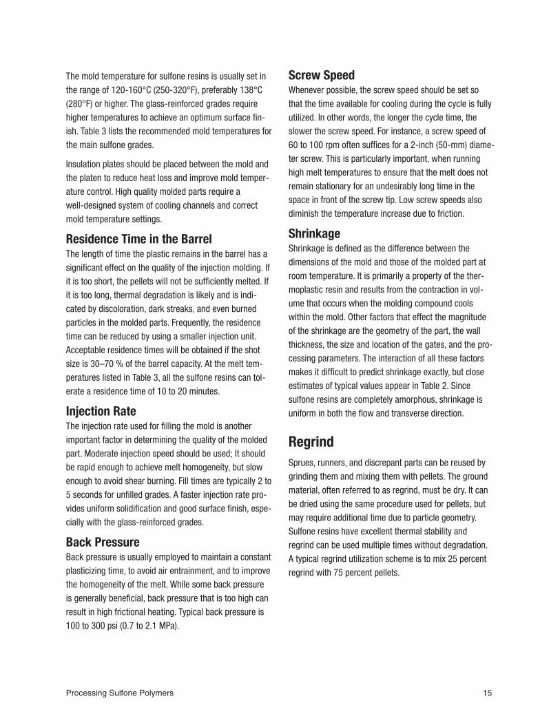
Measuring Residual StressWhen working with fabricated sulfone parts, it is impor-tant to minimize residual or molded-in stress. A proce-dure has been developed for estimating the magnitude ofthe residual stress . The procedure entails exposing theparts to a series of chemical mixtures. The stress levelrequired for crazing to occur for each mixture was deter-mined using specimens at known stress levels. The mix-tures and the stress levels at which they cause crazingare shown in Table 4 for UDEL PSU and in Table 5 forRADEL R PPSU. Contact your Solvay Advanced Polymersrepresentative for assistance with RADEL A PES.
For example, to determine the residual stress of a UDELpolysulfone part, immerse the part for one minute in thefirst mixture, 75% by volume ethanol and 25% by volumeethyl acetate. Then remove the part from the reagent andallow to dry. Drying can be accelerated by blowinglow-pressure compressed air on the surface.
Then inspect the part for crazes. If the part is crazed, theresidual stress is greater than 2,800 psi (19 MPa). If thepart is not crazed, the residual stress is less than 2,800psi (19 MPa). The test is continued with the next mixture.
Immerse the part in the second mixture, remove after oneminute, allow to dry, and inspect for crazing. If crazingoccurs, the residual stress is between 2,200 and 2,800psi (15 and 19 MPa). If crazing does not occur, the resid-ual stress is less than 2,200 psi (15 MPa). The test iscontinued with the next mixture.
Continue in a like manner until crazing occurs, or the partendures the one-minute immersion in the last mixturewithout crazing.
This test has to be conducted on room temperature parts.If testing during production, make sure the part hascooled completely prior to testing.
To maintain accurate stress readings, the reagents mustbe fresh. Over time, the reagents may absorb water,evaporate, or become contaminated, which can lead toerroneous stress indications. Although reagents can becalibrated by using samples with known stress levels, Itmay be more practical to replace your reagents withfresh solvent from the sealed container periodically. If youwant to calibrate your reagents, contact your SolvayAdvanced Polymers representative for assistance.
16 Solvay Advanced Polymers
Ethanol / Ethyl AcetateRatio
Critical Stress forUdel P-1700, psi (MPa)
75 / 25 2800 (19)
50 / 50 2200 (15)
43 / 57 1700 (12)
37 / 63 1300 (9)
25 / 75 800 (6)
0 / 100 400 (3)
Table 4
Residual Stress Testing for UDEL Polysulfone
Ethanol / MEKRatio
Critical Stress forRADEL R-5000, psi (MPa)
50 / 50 3300 (23)
45 / 55 2300 (16)
40 / 60 2200 (15)
25 / 75 2000 (14)
10 / 90 1300 (9)
0 / 100 1200 (8)
Table 5
Residual Stress Testing for RADEL R PPSU
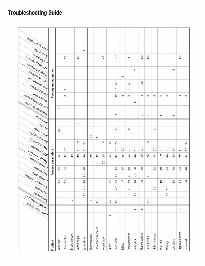
Troubleshooting Guide
Ensureresindryn
ess
Usemoldreleasegrade
Backpressure Coolingtim
e Holdpressureandtim
e
Injectionspeed Injectiontime Injectionpressu
reMeltdecompressio
nMelttemperatureMoldtemperatureNozzle
temperatureScrewspeed ShotsizeSpruebreakIncreasecavity
venting
Increaseclamppressure
Increasedraft Increasegatesize IncreaserunnersizePartwallthicknessChangegatelocation
Cleanandpolishmold
Insulatenozzle Nozzleorific
e Polishspruebushing
Prob
lem
Proc
ess
para
met
ers
Tool
ing
and
equi
pmen
t
Mol
dfla
sh3�
2�4�
5�1
Slow
inje
ctio
n2�
1�3�
4�6
75�
Erra
ticin
ject
ion
1�2�
Nozz
lepl
ugs
3�4�
1�5
26�
Spru
est
icks
6�4�
3�7�
5�9�
8�2�
1
Scre
wsq
ueal
s1�
2�3�
Slow
scre
wre
cove
ry2�
3�1�
Nozz
ledr
ool
3�2�
1�4�
Spla
y1
3�2�
5�4�
Shor
tsho
ts8�
4�2�
9�3�
6�5�
7�1�
1112
1314�
10�
Jetti
ng1�
4�2�
3�6
5
Sink
san
dvo
ids
4�7�
2�3�
5�6�
1�10
89
12�
11�
Parts
stic
k8
3�2�
4�1�
6�5�
97
Ripp
led
surfa
ce9
1�4�
3�2�
75
8�6�
Dark
stre
aks
3�4�
2�1�
5�7
86�
High
shrin
kage
3�2�
4�5�
1�6
Wel
dlin
es4�
3�1�
2�5
6
War
page
2�1�
5�4�
3�6
Low
glos
s3�
4�2�
1�6
5
High
mol
dst
ress
73�
5�2�
1�4
6�
Gate
blus
h1�
4�3�
2�5�
6
ExtrusionSulfone resins can be readily extruded on conventionalextrusion equipment.
PredryingSulfone resins must be dried until the moisture content isbelow 100 ppm prior to extrusion to prevent bubbles inthe extrudate. Please refer to the section on Resin Dryingon page 4.
Extrusion TemperaturesThe starting point extrusion temperatures are shown inTable 6.
If a screw with a relatively shallow metering section isused, higher barrel settings may be necessary to bettercontrol the operation within the pressure and power limi-tations of the equipment.
Screw Design RecommendationsIn general, screws with length-to-diameter ratios from20:1 to 24:1 are recommended. Compression ratios from2.0:1 to 2.5:1 have been shown to give acceptableresults. Screw pitch should equal screw diameter, and thetransition from feed to metering should be gradual. Thetransition and metering sections should be longer thanthe feed section. The transition section should be the lon-gest to provide sufficient time and heat input to ade-quately soften the resin before trying to pump it. A
starting point configuration is 6 flights feed, 12 flightstransition, and 6 flights of metering.
Two-stage screws can also be used to allow vacuumventing where optimal compaction of the melt is desired.A two-stage screw design includes a decompression sec-tion to allow vacuum venting after the first metering sec-tion. The decompression section is then followed byanother transition zone and another metering zone, fol-lowing the design principles described for the singlestage screw.
Generally, screw designs intended for polyolefins will notgive acceptable results with sulfone resins.
Die DesignThe die heaters must be capable of reaching and main-taining temperatures of 430°C (800°F). Since the viscos-ity of sulfone resins is temperature-sensitive, die temper-ature must be closely controlled to provide a uniformextrudate. Insulating the adapter and die is suggested toimprove temperature control and thermal uniformity.
Streamlined dies should always be used. Streamlining theflow channel and incorporating purge plates (i.e., bleederplugs) in the ends of sheeting dies eliminate the possibil-ity of melt stagnation in the die.
Dies should be capable of operating continuously at pres-sures up to 3,500 psi (240 bar). Flow channels, die lips,and lands should be highly polished and chro-mium-plated for optimum extrudate appearance.
Extruded Product Types
WireSulfone resins can be extruded onto wire using asemi-tubing or tubing crosshead die. Wire inlet tempera-tures should approximate that of the polymer melt. Highdrawdown of the polymer melt tube can be achieved withsulfone resins. Vacuum on the crosshead is highly recom-mended to improve adhesion of the polymer tube to thewire. Coated wire should not be quenched but rathercooled slowly using a mister or short water bath.
18 Solvay Advanced Polymers
UDEL PSURADEL or ACUDEL
Resins
Melt TemperatureRange
600° - 700°F(315 - 371°C
650° - 750°F(343 - 400°C)
Barrel Temperature Settings
Feed End 575°F (302°C) 625 - 700°F
(330 - 370°C)
Head End 600 - 640°F
(315 - 337°C)
625 - 700°F
(330 - 370°C)
Table 6
Extrusion Temperatures
FilmThe high melt strength of sulfone resins provides excel-lent drawdown properties for the production of thin film.Slot-cast film possesses high modulus, good impactstrength, and good electrical properties over a wide tem-perature range. The film is heat sealable and can beprinted without pre-treatment.
A typical film extrusion configuration for a 2.5-inch(64-mm) extruder is:
• Die: Standard film dies of coat hanger design andstraight manifold-choker bar design are satisfac-tory. Die lip openings of 0.025 to 0.040 in. (1 to 1.5mm) should be used for 1 to 10 mil (0.025 to 0.250mm) film. Dies must be capable of continuous op-eration at 3,500 psi (240 bar).
• Breaker Plates/Screen packs: Breaker plates arenot required and can cause die lines. But whenthey are used with a screen pack, a consistent, de-fect-free extrudate can be produced.
• Casting Roll: Smaller diameter rolls, less than 10inches (25 cm) are preferred for sulfone polymersbecause of the high roll temperatures , 180°C(350°F), needed. Smaller rolls allow better temper-ature control and more uniform temperaturesacross the roll stack.
SheetStandard round and teardrop manifold sheet dies withchoker bars are satisfactory. Typically, die openings are10 to 20 percent larger than the desired final thickness.In sheet extrusion, the take-off roll temperature must bemaintained high enough to prevent curl and to minimizestrains in the sheet. Either an wrap technique or straight-through calendaring technique is satisfactory, providingthat roll temperatures of 180 to 230°C (350 to 450°F) canbe obtained. Calendaring also requires that a small bank(melt bead) be maintained at the roll nip.
A power shear has been used to cut the sheet to lengthfor sheet thicknesses up to 0.100 inches (2.5 mm). Forgreater thicknesses, sawing is recommended.
Piping and TubingSulfone resins can be extruded into pipe and tubing usingstandard pin and spider assemblies. Control of stock tem-perature is critical to achieving high-quality extrudate.
Stock temperatures of 340 to 370°C (650 to 700°F) aresuggested.
Sizing plate and vacuum tank methods of dimensionalcontrol are satisfactory. For best melt control, the extru-sion die should be 70 to 100 percent larger than the siz-ing die.
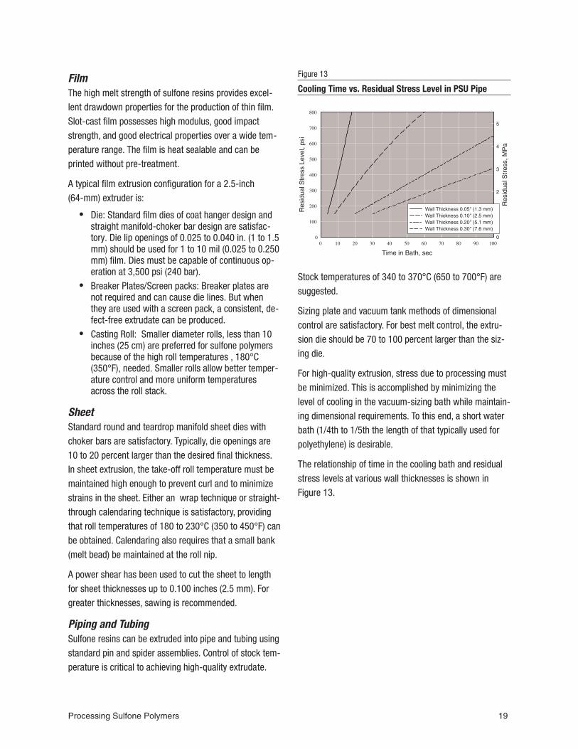
For high-quality extrusion, stress due to processing mustbe minimized. This is accomplished by minimizing thelevel of cooling in the vacuum-sizing bath while maintain-ing dimensional requirements. To this end, a short waterbath (1/4th to 1/5th the length of that typically used forpolyethylene) is desirable.
The relationship of time in the cooling bath and residualstress levels at various wall thicknesses is shown inFigure 13.
Processing Sulfone Polymers 19
Figure 13
Cooling Time vs. Residual Stress Level in PSU Pipe
Start-Up, Shut-Down, and PurgingStart-Up ProcedureIf processing less thermally stable polymers prior to run-ning sulfone resins, it is critical to completely purge outall of the previous polymer. If needed this can be done ina step-wise fashion by bringing the barrel up to an inter-mediate temperature, 288°C (550°F) and purging withmaterial such as high-density polyethylene (HDPE). Thencontinue to bring the barrel temperatures up to sulfonetemperatures, while continuing to slowly turn the screwand trickle in HDPE until temperatures reach 316°C(600°F). Begin to slowly feed the sulfone material. Con-tinue a slow purge until completely switched over to thesulfone resin.
Shut-Down ProcedureIf a shut-down is required during an extrusion run, certainprecautions should be taken. It is not good practice toallow resin to sit stagnant in an extruder for prolongedperiods of time at extrusion temperatures. Some decom-position is likely to occur, and it may prove difficult tostart again and properly purge the machine.
If the shut-down is of a short duration (two hours or less),purge the extruder dry, and then restart using starve feed.For longer shut-downs, the extruder should be purgedwith UDEL polysulfone, and then run dry. The extruderheaters should be turned off and allowed to cool to roomtemperature. To start-up the next day, turn on the dieheaters at least one hour, but preferably two hours,before turning on the extruder heaters. Once the extruderreaches 315 to 343°C (600 to 650°F), the screw can berotated periodically until extrusion temperatures arereached. Start by starve feeding at low screw speedsuntil material comes out of the die.
PurgingSulfone resins can be purged from extrusion processingequipment by a variety of techniques. Because sulfoneresins are tough, stable, high-temperature materials, themost effective purging procedures replace the sulfoneresin with a lower temperature plastic that is more easilyremoved. The generally recommended purging material is
polyethylene, but suitable commercial purgingcompounds can also be used.
The most effective procedure is a step-wise temperaturereduction while purging with a fractional melt-flow,high-density polyethylene. Upon completion of the sulfoneresin extrusion, the machine should be slowly run dry ofmaterial while the temperatures are brought down toaround the 316°C (600°F) range. When the barrel has rundry introduce the polyethylene and extrude until nosulfone resin is evident in the extrudate. At this point thedie, adapter, and breaker plate can be removed andcleaned. If needed. continue to drop the temperatures toaround 288°C (550°F) while slowly purging with polyeth-ylene until no evidence of sulfone resin is seen in theextrudate. At this point stop the extrusion and allow thematerial to sit in the barrel for several minutes, thenpurge dry the polyethylene and pull the screw for finalcleaning if needed. Temperatures can be lowered forshut-down or setup for the next material.
When purging is complete and the extruder has been runto an empty condition, the screw can be removed andboth the barrel and screw brushed clean. If residualsulfone resin can not be removed by brushing, it can beburned off using proper care. An alternative technique issoaking the parts in N-methyl pyrrolidone (NMP) until theresidual resin is softened enough for easy removal.
20 Solvay Advanced Polymers
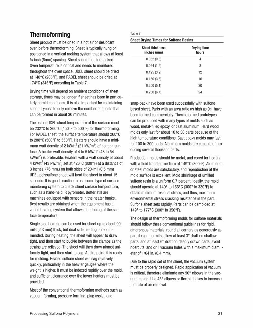
ThermoformingSheet product must be dried in a hot air or desiccantoven before thermoforming. Sheet is typically hung orpositioned in a vertical racking system that allows at least¼ inch (6mm) spacing. Sheet should not be stacked.Oven temperature is critical and needs to monitoredthroughout the oven space. UDEL sheet should be driedat 140°C (285°F), and RADEL sheet should be dried at174°C (345°F) according to Table 7.
Drying time will depend on ambient conditions of sheetstorage, times may be longer if sheet has been in particu-larly humid conditions. It is also important for maintainingsheet dryness to only remove the number of sheets thatcan be formed in about 30 minutes.
The actual UDEL sheet temperature at the surface mustbe 232°C to 260°C (450°F to 500°F) for thermoforming.For RADEL sheet, the surface temperature should 260°Cto 288°C (500°F to 550°F). Heaters should have a mini-mum watt density of 2 kW/ft2 (21 kW/m2) of heating sur-face. A heater watt density of 4 to 5 kW/ft2 (43 to 54kW/m2) is preferable. Heaters with a watt density of about4 kW/ft2 (43 kW/m2) set at 426°C (800°F) at a distance of3 inches. (76 mm.) on both sides of 20-mil (0.5 mm)UDEL polysulfone sheet will heat the sheet in about 15seconds. It is good practice to use some type of surfacemonitoring system to check sheet surface temperature,such as a hand-held IR pyrometer. Better still aremachines equipped with sensors in the heater banks.Best results are obtained when the equipment has azoned heating system that allows fine tuning of the sur-face temperature.
Single side heating can be used for sheet up to about 90mils (2.3 mm) thick, but dual side heating is recom-mended. During heating, the sheet will appear to drawtight, and then start to buckle between the clamps as thestrains are relieved. The sheet will then draw almost uni-formly tight, and then start to sag. At this point, it is readyfor molding. Heated sulfone sheet will sag relativelyquickly, particularly in the heavier gauges where theweight is higher. It must be indexed rapidly over the mold,and sufficient clearance over the lower heaters must beprovided.
Most of the conventional thermoforming methods such asvacuum forming, pressure forming, plug assist, and
snap-back have been used successfully with sulfonebased sheet. Parts with an area ratio as high as 9:1 havebeen formed commercially. Thermoformed prototypescan be produced with many types of molds such aswood, metal-filled epoxy, or cast aluminum. Hard woodmolds only last for about 10 to 30 parts because of thehigh temperature conditions. Cast epoxy molds may lastfor 100 to 300 parts. Aluminum molds are capable of pro-ducing several thousand parts.
Production molds should be metal, and cored for heatingwith a fluid transfer medium at 149°C (300°F). Aluminumor steel molds are satisfactory, and reproduction of themold surface is excellent. Mold shrinkage of unfilledsulfone resin is a uniform 0.7 percent. Ideally, the moldshould operate at 149° to 166°C (300° to 330°F) toobtain minimum residual stress, and thus, maximumenvironmental stress cracking resistance in the part.Sulfone sheet sets rapidly. Parts can be demolded at149° to 177°C (300° to 350°F).
The design of thermoforming molds for sulfone materialsshould follow these conventional guidelines for rigid,amorphous materials: round all corners as generously aspart design permits, allow at least 3° draft on shallowparts, and at least 6° draft on deeply drawn parts, avoidndercuts, and drill vacuum holes with a maximum diam -eter of 1/64 in. (0.4 mm).
Due to the rapid set of the sheet, the vacuum systemmust be properly designed. Rapid application of vacuumis critical, therefore eliminate any 90° elbows in the vac-uum piping. Use 45° elbows or flexible hoses to increasethe rate of air removal.
Processing Sulfone Polymers 21
Sheet thicknessInches (mm)
Drying timehours
0.032 (0.8) 4
0.064 (1.6) 8
0.125 (3.2) 12
0.150 (3.8) 16
0.200 (5.1) 20
0.250 (6.4) 24
Table 7
Sheet Drying Times for Sulfone Resins

Index
AACUDEL- 3
BBack Pressure- 15Barrel Capacity- 12Breaker Plates- 19
CCapacity
Barrel- 12Cavity Layout- 9ceramic band heaters- 12Check Valves- 12Clamp- 12Controls- 12Cooling- 14
DDiaphragm Gates- 10Die Design- 18Dies- 18 - 19Draft- 11Drying- 4
EEdge Gates- 10Ejection
Part- 11Ejector Pins- 12Extrusion- 18Extrusion Temperatures- 18
FFilm- 19Flow- 6
GGate Location- 11Gates
Diaphragm- 10Edge- 10Submarine- 10Tunnel- 10
Gating- 10Sprue- 10
HH-13- 7
Holding Pressure- 13Hot Runner Molds- 9
IInjection Molding- 12
Equipment- 12Injection Molding- 7Injection Rate- 15Insulation- 15Introduction- 3
MMachine Settings- 14Maintenance- 12Mica band heaters- 12Mold Design- 7Mold Filling- 13Mold Temperature- 14Mold Types- 8Molding- 7Molding Equipment- 12Molds- 7
Hot Runner- 9Three-plate- 8Two-Plate- 8
NNozzles- 12
PP-20- 7Packing- 13Part Ejection- 15Piping- 19polyethersulfone- 3Polymer Injection- 13polyphenylsulfone- 3polyphenylsulfone blends- 3polysulfone- 3Pressure
Back- 15Purging- 20
RRADEL A- 3RADEL R- 3Regrind- 15Residence Time- 15Residual Stress- 16
Resin Drying- 4Resin Flow- 6Rheology- 5Runner Systems- 9
SS-7- 7Screenpacks- 19Screw Design- 12
Extrusion- 18Screw Speed- 15Screw Tips- 12Sheet- 19Shrinkage- 15Shut-Down- 20Sprue Gating- 10Start-Up- 20steel- 7Stripper Plates- 12Sulfone Polymers- 3surface treatments- 7
TTemperature
Barrel- 14Mold- 14
TemperaturesExtrusion- 18
Thermal Management- 7Thermoforming- 21Three-Plate Molds- 8Tool steels- 7Transfer Position- 13Troubleshooting- 17Tubing- 19Two-Plate Molds- 8
UUDEL- 3
VVenting- 11Viscosity- 5
WWire- 18

Solvay Advanced Polymers, L.L.C.4500 McGinnis Ferry RoadAlpharetta, GA 30005-3914USAPhone: +1.770.772.8200
+1.800.621.4557 (U.S. only)Fax: +1.770.772.8454
Solvay Advanced Polymers has offices in the Americas, Europe, and
Asia. Please visit our website at www.solvayadvancedpolymers.com
to locate the office nearest to you.
Product and Technical LiteratureTo our actual knowledge, the information contained herein is accurate
as of the date of this document. However, neither Solvay Advanced
Polymers, L.L.C. nor any of its affiliates makes any warranty, express
or implied, or accepts any liability in connection with this information
or its use. This information is for use by technically skilled persons at
their own discretion and risk and does not relate to the use of this
product in combination with any other substance or any other process.
This is not a license under any patent or other proprietary right.
The user alone must finally determine suitability of any information or
material for any contemplated use, the manner of use and whether any
patents are infringed. This information gives typical properties only and
is not to be used for specification purposes. Solvay Advanced
Polymers, L.L.C. reserves the right to make additions, deletions, or
modifications to the information at any time without prior notification.
Health and Safety Information Material Safety Data Sheets (MSDS) for products of Solvay Advanced
Polymers are available upon request from your sales representative or
by writing to the address shown on this document. The appropriate
MSDS should be consulted before using any of our products.
ACUDEL, UDEL and RADEL are registered trademarks of
Solvay Advanced Polymers, L.L.C.
G-50427 © 2006 Solvay Advanced Polymers, L.L.C. All rights reserved. D 05/06


![Crystal structure of bis[bis(4-azaniumylphenyl) sulfone ......[bis(4,40-diazaniumylphenyl) sulfone] tetranitrate monohydrate}, the cations are conformationally similar, with comparable](https://static.fdocuments.net/doc/165x107/60b0786ebd8ffd67d34c0b4e/crystal-structure-of-bisbis4-azaniumylphenyl-sulfone-bis440-diazaniumylphenyl.jpg)