
Subset098:RBC Safe Communication Interface
109
© This document has been developed and released by UNISIG Subset-098 v3.0.0 RBC-RBC Safe Communication Interface Page 1/109 ERTMS/ETCS RBC-RBC Safe Communication Interface REF : Subset-098 ISSUE: 3.0.0 DATE: 29 February 2012 Company Technical Approval Management approval ALSTOM ANSALDO BOMBARDIER INVENSYS SIEMENS THALES
-
Upload
phungduong -
Category
Documents
-
view
279 -
download
0
Transcript of Subset098:RBC Safe Communication Interface

© This document has been developed and released by UNISIG
Subset-098 v3.0.0 RBC-RBC Safe Communication Interface Page 1/109
ERTMS/ETCS
RBC-RBC Safe Communication Interface
REF : Subset-098
ISSUE: 3.0.0
DATE: 29 February 2012
Company Technical Approval Management approval
ALSTOM
ANSALDO
BOMBARDIER
INVENSYS
SIEMENS
THALES
© This document has been developed and released by UNISIG
Subset-098 v3.0.0 RBC-RBC Safe Communication Interface Page 2/109
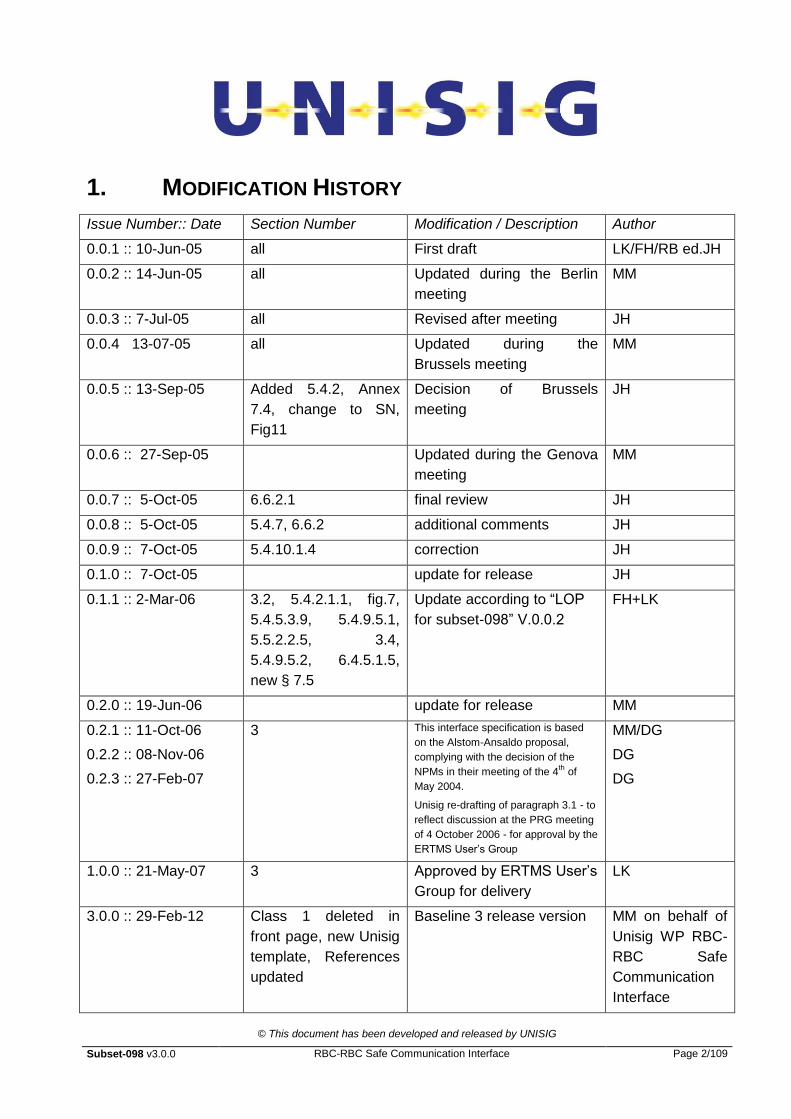
1. MODIFICATION HISTORY
Issue Number:: Date Section Number Modification / Description Author
0.0.1 :: 10-Jun-05 all First draft LK/FH/RB ed.JH
0.0.2 :: 14-Jun-05 all Updated during the Berlin
meeting
MM
0.0.3 :: 7-Jul-05 all Revised after meeting JH
0.0.4 13-07-05 all Updated during the
Brussels meeting
MM
0.0.5 :: 13-Sep-05 Added 5.4.2, Annex
7.4, change to SN,
Fig11
Decision of Brussels
meeting
JH
0.0.6 :: 27-Sep-05 Updated during the Genova
meeting
MM
0.0.7 :: 5-Oct-05 6.6.2.1 final review JH
0.0.8 :: 5-Oct-05 5.4.7, 6.6.2 additional comments JH
0.0.9 :: 7-Oct-05 5.4.10.1.4 correction JH
0.1.0 :: 7-Oct-05 update for release JH
0.1.1 :: 2-Mar-06 3.2, 5.4.2.1.1, fig.7,
5.4.5.3.9, 5.4.9.5.1,
5.5.2.2.5, 3.4,
5.4.9.5.2, 6.4.5.1.5,
new § 7.5
Update according to “LOP
for subset-098” V.0.0.2
FH+LK
0.2.0 :: 19-Jun-06 update for release MM
0.2.1 :: 11-Oct-06
0.2.2 :: 08-Nov-06
0.2.3 :: 27-Feb-07
3 This interface specification is based
on the Alstom-Ansaldo proposal,
complying with the decision of the
NPMs in their meeting of the 4th
of
May 2004.
Unisig re-drafting of paragraph 3.1 - to
reflect discussion at the PRG meeting
of 4 October 2006 - for approval by the
ERTMS User‟s Group
MM/DG
DG
DG
1.0.0 :: 21-May-07 3 Approved by ERTMS User‟s
Group for delivery
LK
3.0.0 :: 29-Feb-12 Class 1 deleted in
front page, new Unisig
template, References
updated
Baseline 3 release version MM on behalf of
Unisig WP RBC-
RBC Safe
Communication
Interface

© This document has been developed and released by UNISIG
Subset-098 v3.0.0 RBC-RBC Safe Communication Interface Page 3/109
2. TABLE OF CONTENTS
1. MODIFICATION HISTORY ................................................................................................................ 2
2. TABLE OF CONTENTS .................................................................................................................... 3
3. INTRODUCTION ............................................................................................................................. 6
3.1 Purpose and applicability .................................................................................................. 6
3.2 References ....................................................................................................................... 6
3.3 Terms and definitions ........................................................................................................ 7
3.4 Abbreviations .................................................................................................................... 7
4. REFERENCE ARCHITECTURE .......................................................................................................... 9
4.1 Overview ........................................................................................................................... 9
4.2 RBC/RBC Safe Communication Interface ....................................................................... 10
4.3 Layer Functions .............................................................................................................. 12
4.3.1 Safe Functional Module ........................................................................................... 12
4.3.2 Communication Functional Module .......................................................................... 13
4.4 Classification of transmission systems ............................................................................ 13
4.5 Assumptions ................................................................................................................... 13
5. SAFE FUNCTIONAL MODULE ........................................................................................................ 14
5.1 Introduction ..................................................................................................................... 14
5.2 Functions of the Safe functional module ......................................................................... 14
5.3 Euroradio SL implementation .......................................................................................... 16
5.4 Safe application intermediate sub-layer .......................................................................... 17
5.4.1 General overview ..................................................................................................... 17
5.4.2 Interface to SAI Services ......................................................................................... 18
5.4.3 Interface to the Euroradio SL ................................................................................... 19
5.4.4 Message structure ................................................................................................... 19
5.4.5 SAI Protocol ............................................................................................................. 22
5.4.6 Message type field ................................................................................................... 27
5.4.7 Sequence numbering defence technique ................................................................. 28
5.4.8 Triple Time Stamping ............................................................................................... 31
5.4.9 EC defence technique .............................................................................................. 44
5.4.10 Error handling .......................................................................................................... 52
5.5 Configuration data and rules ........................................................................................... 53
5.5.1 Introduction .............................................................................................................. 53
5.5.2 Connection initiation rules ........................................................................................ 53
© This document has been developed and released by UNISIG
Subset-098 v3.0.0 RBC-RBC Safe Communication Interface Page 4/109
5.5.3 Guideline for TTS parameter definition .................................................................... 54
5.5.4 Guideline for EC parameter definition ...................................................................... 56
5.5.5 Guideline for error handling ...................................................................................... 56
5.6 TTS examples ................................................................................................................. 57
6. COMMUNICATION FUNCTIONAL MODULE ....................................................................................... 62
6.1 General ........................................................................................................................... 62
6.2 Overview ......................................................................................................................... 62
6.2.1 General description .................................................................................................. 62
6.3 Functional Characteristics ............................................................................................... 63
6.3.1 TCP equivalence to Transport Class 2 service and protocol .................................... 63
6.3.2 Class of Service ....................................................................................................... 64
6.3.3 Class A request ....................................................................................................... 65
6.3.4 Class D request ....................................................................................................... 65
6.3.5 Relationship between TS-User and TCP .................................................................. 65
6.3.6 Transport Priorities ................................................................................................... 67
6.4 Transport Layer Emulation using an Adaptation Layer Entity .......................................... 67
6.4.1 General Overview .................................................................................................... 67
6.4.2 Interface Service Definition ...................................................................................... 68
6.4.3 Mapping of X.214 primitives to TCP ......................................................................... 71
6.4.4 Addressing ............................................................................................................... 72
6.4.5 Adaptation Layer Packet Format (ALEPKT) ............................................................. 72
6.5 Interface Protocol Definition ............................................................................................ 74
6.5.1 Using TCP/IP to provide ISO Transport Class 2 protocol ......................................... 74
6.5.2 ALE operation .......................................................................................................... 77
6.5.3 Data transfer ............................................................................................................ 83
6.5.4 Connection release .................................................................................................. 84
6.6 Operation and Redundancy Management for different Classes of Service ..................... 89
6.6.1 Class A (optional for implementation) ...................................................................... 89
6.6.2 Class D .................................................................................................................... 92
6.6.3 Summary of ALEPKT ............................................................................................... 94
6.7 Management of Adaptation Layer - ALEPKT Error Handling ........................................... 95
6.8 Lower layers of protocol stack ......................................................................................... 97
6.8.1 Introduction .............................................................................................................. 97
6.8.2 TCP Parameter Negotiation (Mandatory) ................................................................. 97
6.8.3 Network Service Definition ....................................................................................... 97
© This document has been developed and released by UNISIG
Subset-098 v3.0.0 RBC-RBC Safe Communication Interface Page 5/109
6.8.4 Network Protocol ...................................................................................................... 98
6.9 Adaptation Layer Configuration and Management .......................................................... 98
6.9.1 General .................................................................................................................... 98
6.9.2 Timer Parameter ...................................................................................................... 98
6.9.3 Call and ID-Management (Adaptation Layer and TCP) ............................................ 98
7. INFORMATIVE ANNEX .................................................................................................................. 99
7.1 TCP Parameter Negotiation ............................................................................................ 99
7.1.1 TCP Service options ................................................................................................ 99
7.2 Address Mapping ............................................................................................................ 99
7.3 Data Link Layer ............................................................................................................. 102
7.3.1 Ethernet ................................................................................................................. 102
7.3.2 Media Access Control ............................................................................................ 102
7.3.3 Wide Area connections .......................................................................................... 102
7.4 Guideline for Key Management ..................................................................................... 102
7.4.1 Scope .................................................................................................................... 102
7.4.2 KM Concepts and Principles .................................................................................. 102
7.4.3 Phases and parties involved In KMS ...................................................................... 103
7.4.4 General Principles .................................................................................................. 104
7.4.5 Key Hierarchy ........................................................................................................ 105
7.4.6 Key assignment ..................................................................................................... 105
7.4.7 Basic KM Functions ............................................................................................... 106
7.4.8 Abbreviations and Definitions ................................................................................. 108
7.5 Examples of Checksum results ..................................................................................... 109

© This document has been developed and released by UNISIG
Subset-098 v3.0.0 RBC-RBC Safe Communication Interface Page 6/109
3. INTRODUCTION
3.1 Purpose and applicability
3.1.1.1.1 This document specifies the functional architecture and the protocols for exchange of
safety-related messages between RBCs via closed or open networks.
3.1.1.1.2 It is applicable to the RBC-RBC safe communication interface .
3.1.1.1.3 This specification shall be used for the interface between RBCs from single or
different suppliers unless the railway(s), as well as the supplier(s), on both sides of the
interface, agree to use a different specification. In case of disagreement by any of the
parties, Subset-098 shall be used.
3.2 References
3.2.1.1.1 This specification incorporates provisions from other publications by means of dated or
undated references. The normative references are cited in the text in the appropriate
places, the publications are listed hereafter. As to dated references, subsequent
amendments to or revisions of any of these publications apply to this architecture
specification only when incorporated by amendment or revision. For undated
references, the latest edition of the publication referred to applies.
Name Date Description
EN 50159-1 03.01 Safety-Related Communication in Closed Transmission
Systems
EN 50159-2 03.01 Safety-Related Communication in Open Transmission
Systems
Subset-026 ERTMS/ETCS; System Requirements Specification
Subset-037 EuroRadio FIS
Subset-038 Off-line Key Management FIS
Subset-039 FIS for RBC/RBC Handover
ITU-T X.214 11.93 Information Technology; Open Systems Interconnection;
Transport service definition
ITU-T X.224 11.93 Information Technology; Open Systems Interconnection;
Protocol for providing the OSI connection-mode transport
service
RFC0791 01.09.81 Internet Protocol v4
RFC2460 12.98 Internet Protocol v6
© This document has been developed and released by UNISIG
Subset-098 v3.0.0 RBC-RBC Safe Communication Interface Page 7/109
Name Date Description
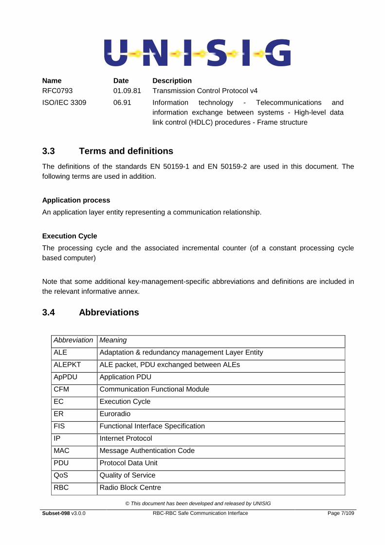
RFC0793 01.09.81 Transmission Control Protocol v4
ISO/IEC 3309 06.91 Information technology - Telecommunications and
information exchange between systems - High-level data
link control (HDLC) procedures - Frame structure
3.3 Terms and definitions
The definitions of the standards EN 50159-1 and EN 50159-2 are used in this document. The
following terms are used in addition.
Application process
An application layer entity representing a communication relationship.
Execution Cycle
The processing cycle and the associated incremental counter (of a constant processing cycle
based computer)
Note that some additional key-management-specific abbreviations and definitions are included in
the relevant informative annex.
3.4 Abbreviations
Abbreviation Meaning
ALE Adaptation & redundancy management Layer Entity
ALEPKT ALE packet, PDU exchanged between ALEs
ApPDU Application PDU
CFM Communication Functional Module
EC Execution Cycle
ER Euroradio
FIS Functional Interface Specification
IP Internet Protocol
MAC Message Authentication Code
PDU Protocol Data Unit
QoS Quality of Service
RBC Radio Block Centre

© This document has been developed and released by UNISIG
Subset-098 v3.0.0 RBC-RBC Safe Communication Interface Page 8/109
Abbreviation Meaning
SaCEPID Safety Connection End Point Identifier
SAI Safe Application Intermediate sub-layer
SAP Service Access Point
SaPDU Safety Layer Protocol Data Unit
SaS Safety Service
SFM Safe Functional Module
SL Safety Layer
SN Sequence Number
TCEPID Transport Connection End Point Identifier
TCP Transport Control Protocol
TPDU Transport Protocol Data Unit
TS Transport Service
TSAP Transport Layer Service Access Point
TTS Triple Timestamp
© This document has been developed and released by UNISIG
Subset-098 v3.0.0 RBC-RBC Safe Communication Interface Page 9/109
4. REFERENCE ARCHITECTURE
4.1 Overview
4.1.1.1.1 A closed network has been defined by EN 50159-1 as “A transmission system with a
fixed number or fixed maximum number of participants linked by a transmission
system with well known and fixed properties, and where the risk of unauthorised
access is considered negligible”.
4.1.1.1.2 An open network has been defined by EN 50159-2 as “A transmission system with an
unknown number of participants, having unknown, variable and non-trusted properties,
used for unknown telecommunication services, and for which the risk of unauthorised
access shall be assessed.”
4.1.1.1.3 Both network types are considered.
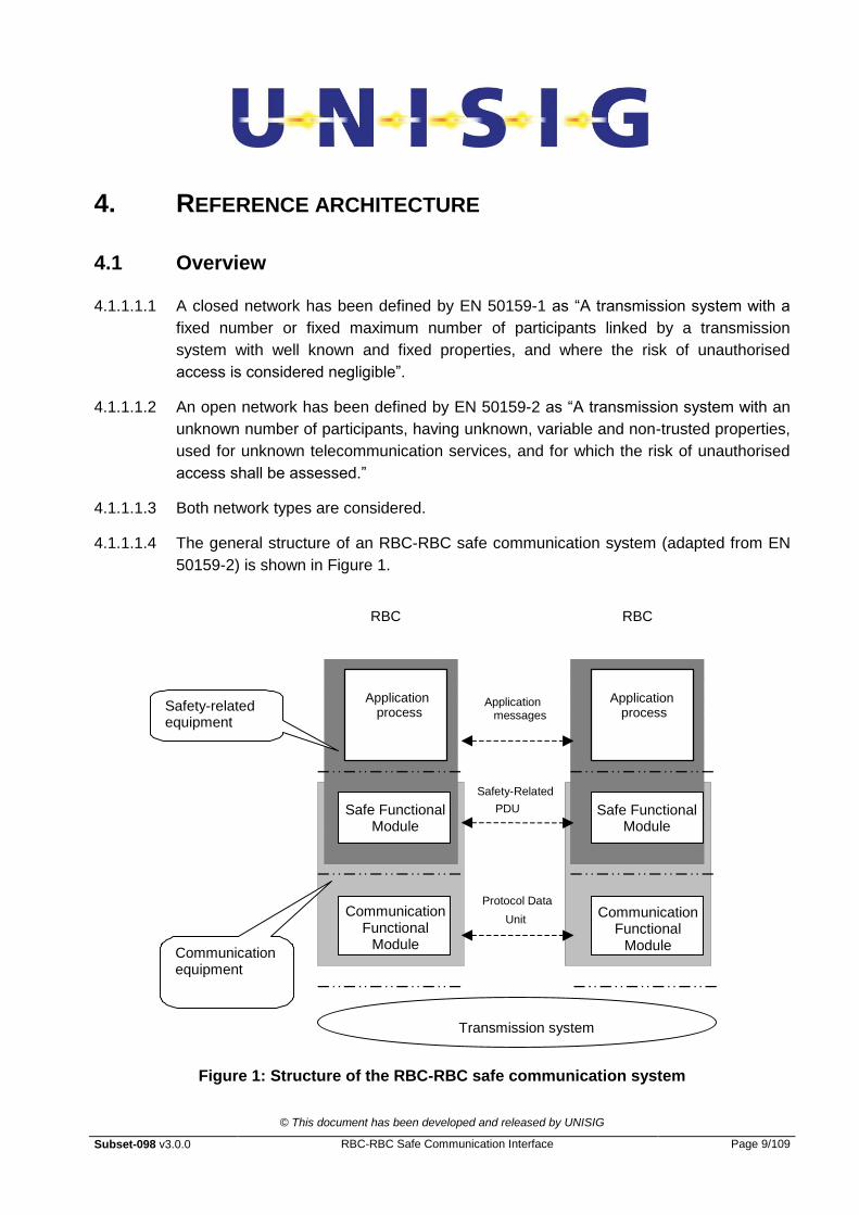
4.1.1.1.4 The general structure of an RBC-RBC safe communication system (adapted from EN
50159-2) is shown in Figure 1.
RBC
Safety-Related
PDU
Application messages
Protocol Data
Unit
Transmission system
RBC
Communication equipment
Safety-related equipment
Application process
Safe Functional Module
Application process
Safe Functional Module
Communication Functional
Module
Communication Functional
Module
Figure 1: Structure of the RBC-RBC safe communication system

© This document has been developed and released by UNISIG
Subset-098 v3.0.0 RBC-RBC Safe Communication Interface Page 10/109
4.2 RBC/RBC Safe Communication Interface
4.2.1.1.1 Without restriction to the implementation of the internal layering this section describes
the functional architecture of the RBC-RBC safe communication system. It must not be
understood as an implementation in terms of software layers.
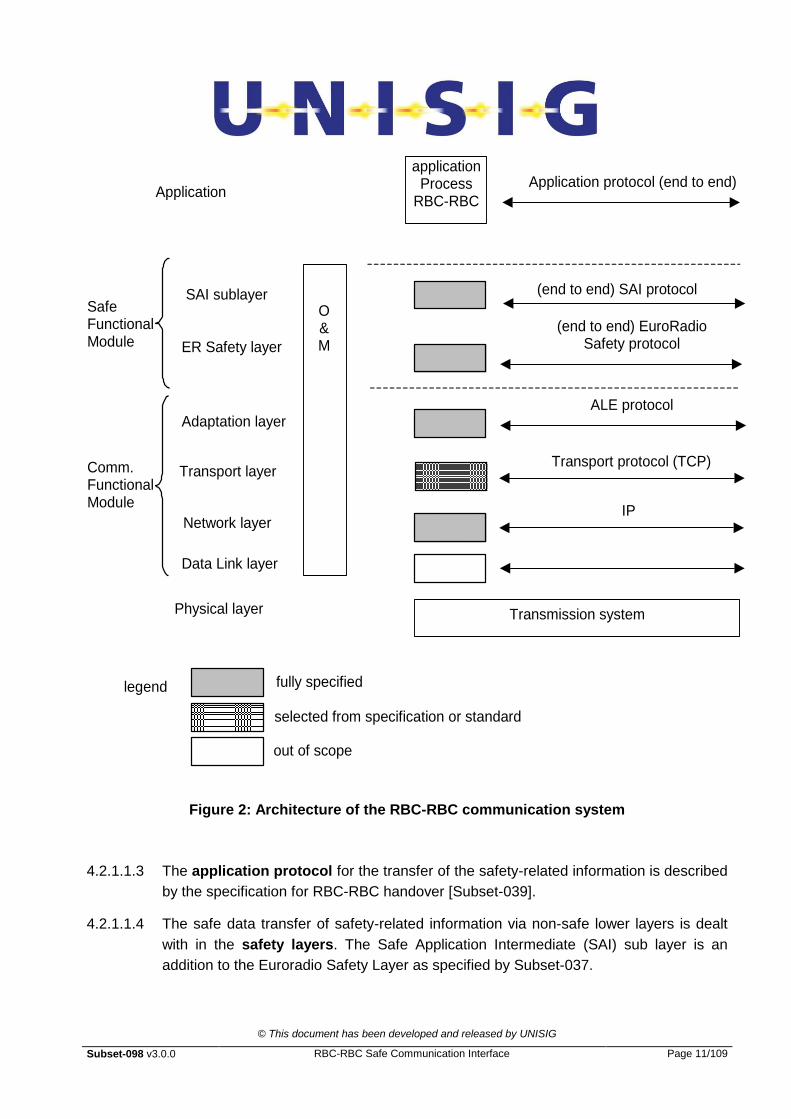
4.2.1.1.2 The RBC-RBC safe communication interface is layered. The layers covered by this
interface specification are shown in Figure 2 as grey or hatched fields. A functional
description for the individual layers is given in the sections below.
© This document has been developed and released by UNISIG
Subset-098 v3.0.0 RBC-RBC Safe Communication Interface Page 11/109
Data Link layer
Network layer
Transport layer
Physical layer
(end to end) EuroRadio Safety protocol
Application protocol (end to end) Application
application Process
RBC-RBC
SAI sublayer O & M
Safe Functional Module
Comm. Functional Module
ALE protocol Adaptation layer
Transport protocol (TCP)
(end to end) SAI protocol
legend
ER Safety layer
IP
selected from specification or standard
out of scope
fully specified
Transmission system
Figure 2: Architecture of the RBC-RBC communication system
4.2.1.1.3 The application protocol for the transfer of the safety-related information is described
by the specification for RBC-RBC handover [Subset-039].
4.2.1.1.4 The safe data transfer of safety-related information via non-safe lower layers is dealt
with in the safety layers. The Safe Application Intermediate (SAI) sub layer is an
addition to the Euroradio Safety Layer as specified by Subset-037.

© This document has been developed and released by UNISIG
Subset-098 v3.0.0 RBC-RBC Safe Communication Interface Page 12/109
4.2.1.1.5 The adaptation layer deals with the adaptation between Euroradio Safety Layer and
the transport layer and provides the redundancy handling.
4.2.1.1.6 The transport layer protocol is TCP [RFC0793]. The retransmission function is
provided by the normal mechanism of TCP.
4.2.1.1.7 The network layer protocol is IP [RFC0791].
4.2.1.1.8 The data link layer will not be specified by this specification.
4.2.1.1.9 The transmission system i.e. the (public or railway owned) network is out of scope
for this specification.
4.2.1.1.10 The Operations and Maintenance (O&M) stack (e.g. a local diagnostic system) is a
matter of an implementation. It is out of scope for this specification.
4.3 Layer Functions
4.3.1 Safe Functional Module
4.3.1.1.1 The safety layers provided by this module have to detect and provide adequate
defences to the threats as specified by EN 50159-1 and EN 50159-2.
4.3.1.1.2 The safety layers realise the following common safety-related transmission functions:
Message authenticity (origin and destination)
Message sequence integrity
Message timeliness
Message integrity
Reporting of safety relevant errors
Configuration management (of the RBC-RBC safe communication protocol stack)
Access protection
4.3.1.1.3 The EuroRadio safety layer provides:
Message authenticity (origin and destination)
Message integrity
Access protection
4.3.1.1.4 The SAI sub layer provides the required additional functions.
4.3.1.1.5 Protection against a sequence error is achieved by adding a sequence number field to
the user data.

© This document has been developed and released by UNISIG
Subset-098 v3.0.0 RBC-RBC Safe Communication Interface Page 13/109
4.3.1.1.6 Providing data protection against data obsolescence is achieved by adding a triple time
stamp or an EC counter to the user data.
4.3.1.1.7 The EC and TTS provide the same level of protection against the delay threat.
4.3.1.1.8 The Triple Time Stamp is the standard solution whilst the EC counter will remain as an
option. The EC counter option can be used for a specific project, if agreed by the
relevant parties to the contract.
4.3.2 Communication Functional Module
4.3.2.1.1 The Communication Functional Module provides the non-trusted transmission.
4.3.2.1.2 The module provides the following functions:
Adaptation between Euroradio Safety Layer and the transport layer
Redundancy to fulfil availability requirements
Reliable, transparent and bi-directional transfer of data
Retransmission of protocol data units, if necessary
Monitoring of channel availability
4.4 Classification of transmission systems
4.4.1.1.1 To avoid any application constraints for this specification no assumptions about the
open transmission system class value shall be made. Thus Class 7 [see EN 50159-2]
shall be used as a reference, i.e. the class having the highest safety risk.
4.5 Assumptions
4.5.1.1.1 The following are assumed:
„High priority‟ messages [Subset-037] are not required;
Multiplexing is presently not required, nevertheless this feature may be achieved by
using one TCP link per logical connection;
No explicit flow control is implemented;
Safety related errors detected by the SFM may be handled outside SAI;
User data not longer than 1000 octets
© This document has been developed and released by UNISIG
Subset-098 v3.0.0 RBC-RBC Safe Communication Interface Page 14/109
5. SAFE FUNCTIONAL MODULE
5.1 Introduction
5.1.1.1.1 This section specifies the Safe Functional Module (SFM).
5.1.1.1.2 It describes only the functional interface to be respected in order to ensure
interworking at the safe functional module level.
5.1.1.1.3 The safe functional module is composed of:
the Euroradio SL
the SAI sub-layer
5.1.1.1.4 The combination of these two layers provides a complete protection against the threat
identified in the document EN 50159-2.
5.2 Functions of the Safe functional module
5.2.1.1.1 The safe functional module shall provide safety services compliant with the class 7
open transmission system.
5.2.1.1.2 This section specifies how the defence techniques are implemented in the Safe
Functional Module.
5.2.1.1.3 According to standard EN 50159-2 all possible threats to a generic transmission
system are listed below (see EN 50159-2 for definition):
Repetition
Deletion
Insertion
Re-sequencing
Corruption
Delay
Masquerade
5.2.1.1.4 To reduce the risk associated with those threats identified in the standard, the following
safety services shall be provided by the Safety Functional Module (see EN 50159-2 for
definitions):
Message Authenticity
Message Integrity

© This document has been developed and released by UNISIG
Subset-098 v3.0.0 RBC-RBC Safe Communication Interface Page 15/109
Message Timeliness
Message Sequence
5.2.1.1.5 The combination of the Euroradio SL and of the Safe Application Intermediate sub-
layer provides a safe protection strategy for an open transmission system.
5.2.1.1.6 The Euroradio SL protects against the following threats:
Corruption
Masquerade
Insertion
5.2.1.1.7 The protection is achieved by the addition of a safety code (Message Authentication
Code, or MAC) and a connection identifier (source and destination identifier).
5.2.1.1.8 The SAI protects against the following threats:
Delay
Re-sequencing
Deletion
Repetition
5.2.1.1.9 The protection is achieved by the addition of a delay defence technique (EC or triple
time stamping) and a sequence number.
5.2.1.1.10 The following table illustrates the protection provided by the safe functional module:
Defences
Threats Sequence
Number
Time
stamp/
EC
Time
out
Feed-
back
message
Source and
destination
Identifier
Message
Identification
Proc
Safety
code
Cryptographic
techniques
Repetition X
Deletion X
Insertion X
Re-sequencing X
Corruption X
Delay X
Masquerade X
Table 1: Defence techniques in the safe functional module
© This document has been developed and released by UNISIG
Subset-098 v3.0.0 RBC-RBC Safe Communication Interface Page 16/109
5.3 Euroradio SL implementation
5.3.1.1.1 The Euroradio SL is specified by [Subset-037].
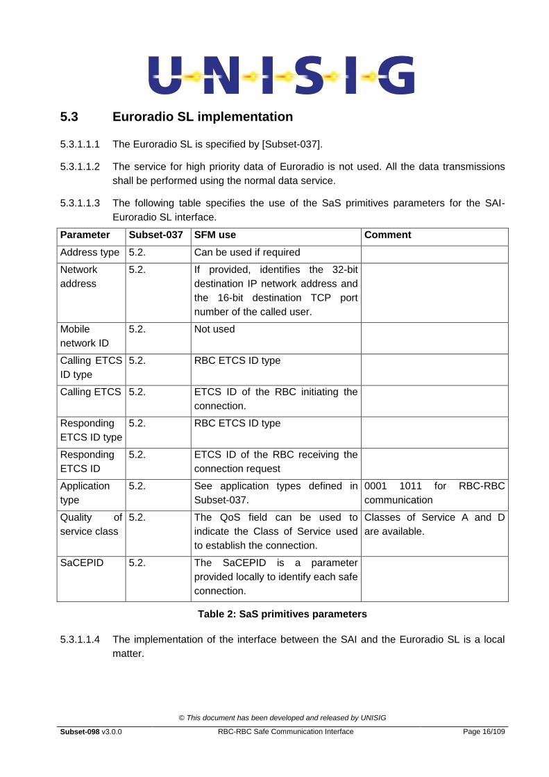
5.3.1.1.2 The service for high priority data of Euroradio is not used. All the data transmissions
shall be performed using the normal data service.
5.3.1.1.3 The following table specifies the use of the SaS primitives parameters for the SAI-
Euroradio SL interface.
Parameter Subset-037 SFM use Comment
Address type 5.2. Can be used if required
Network
address
5.2. If provided, identifies the 32-bit
destination IP network address and
the 16-bit destination TCP port
number of the called user.
Mobile
network ID
5.2. Not used
Calling ETCS
ID type
5.2. RBC ETCS ID type
Calling ETCS 5.2. ETCS ID of the RBC initiating the
connection.
Responding
ETCS ID type
5.2. RBC ETCS ID type
Responding
ETCS ID
5.2. ETCS ID of the RBC receiving the
connection request
Application
type
5.2. See application types defined in
Subset-037.
0001 1011 for RBC-RBC
communication
Quality of
service class
5.2. The QoS field can be used to
indicate the Class of Service used
to establish the connection.
Classes of Service A and D
are available.
SaCEPID 5.2. The SaCEPID is a parameter
provided locally to identify each safe
connection.
Table 2: SaS primitives parameters
5.3.1.1.4 The implementation of the interface between the SAI and the Euroradio SL is a local
matter.

© This document has been developed and released by UNISIG
Subset-098 v3.0.0 RBC-RBC Safe Communication Interface Page 17/109
5.3.1.1.5 The following table specifies the configuration of the Euroradio SL for the RBC-RBC
Safe Communication Interface:
Parameter Subset-037 SFM value Comment
Maximum
length of SaS
user data
5.3. for RBC-RBC hand over:
1000 bytes
Testab 7.3.2 max. applied value: 40 sec applied value for interworking with
Euroradio recommended 40 sec,
lower values are possible for RBC to
RBC communication (see also
§6.9.2.1.1)
Table 3: Euroradio SL configuration
5.4 Safe application intermediate sub-layer
5.4.1 General overview
5.4.1.1.1 The safe application intermediate sub-layer provides:
data protection by sequence number and time stamping/EC counter
the interface to the application
the interface to the Euroradio SL
5.4.1.1.2 Data protection against repetition, deletion and re-sequencing shall be achieved by
adding a sequence number field to the user data.
5.4.1.1.3 Providing protection against obsolescence is achieved adding a triple time stamp or an
EC counter to the user data.
5.4.1.1.4 The time stamping defence technique is founded on the clock-offset computation
between the sender and the receiver.
5.4.1.1.5 To allow the clock offset estimation between the sender and the receiver, an
initialisation procedure shall be performed. This initialisation procedure requires the
definition of a message type in the SAI header.
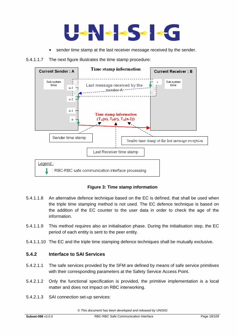
5.4.1.1.6 Considering a sender device sending a data message to a receiver device, this triple
time stamping method consists of adding:
the sender time stamp for the data transmission;
the receiver time stamp of the last message sent by the receiver to the current
sender;
© This document has been developed and released by UNISIG
Subset-098 v3.0.0 RBC-RBC Safe Communication Interface Page 18/109
sender time stamp at the last receiver message received by the sender.
5.4.1.1.7 The next figure illustrates the time stamp procedure:
Figure 3: Time stamp information
5.4.1.1.8 An alternative defence technique based on the EC is defined, that shall be used when
the triple time stamping method is not used. The EC defence technique is based on
the addition of the EC counter to the user data in order to check the age of the
information.
5.4.1.1.9 This method requires also an initialisation phase. During the initialisation step, the EC
period of each entity is sent to the peer entity.
5.4.1.1.10 The EC and the triple time stamping defence techniques shall be mutually exclusive.
5.4.2 Interface to SAI Services
5.4.2.1.1 The safe services provided by the SFM are defined by means of safe service primitives
with their corresponding parameters at the Safety Service Access Point.
5.4.2.1.2 Only the functional specification is provided, the primitive implementation is a local
matter and does not impact on RBC interworking.
5.4.2.1.3 SAI connection set-up services:

© This document has been developed and released by UNISIG
Subset-098 v3.0.0 RBC-RBC Safe Communication Interface Page 19/109
SAI-CONNECT.request initiates the establishment of a connection at the SAI level.
SAI-CONNECT.indication is used by the called SAI entity to inform the called SAI
user about the SAI connection establishment request.
SAI-CONNECT.response is used by the responding SAI user to accept the
connection to the SAI entity.
SAI-CONNECT.confirm is used by the initiating SAI entity to inform the calling SAI
user about the successful establishment of the SAI connection after a response of
the called peer entity was obtained.
5.4.2.1.4 SAI data transfer services:
SAI-DATA.request is used by an SAI user to transmit application data to the peer
entity.
SAI-DATA.indication indicates to the SAI user that data have been received
successfully from the peer entity.
5.4.2.1.5 SAI connection release services:
SAI-DISCONNECT.request is used by the SAI user to enforce a release of the SAI
connection
SAI-DISCONNECT.indication is used to inform the SAI user about an SAI
connection release.
5.4.3 Interface to the Euroradio SL
5.4.3.1 The safe application intermediate sub-layer is functionally above the Euroradio SL.
5.4.3.2 The re-use of the Euroradio SL constrains the SAI design. To interface the Euroradio
SL, the SAI shall be able to be interfaced with the “Interface to safe service” specified
in Subset-037.
5.4.4 Message structure
5.4.4.1.1 The next figure illustrates the message structure.

© This document has been developed and released by UNISIG
Subset-098 v3.0.0 RBC-RBC Safe Communication Interface Page 20/109
Header Application info
User data SAI header
User data MAC Euroradio header
User data ALE header
Communication header
User data Communication footer
Application
Safe application intermediate sublayer
Euroradio safety layer :
Adaptation layer :
Communication layers :
Trackside subsystem A
Trackside subsystem B
Message exchanged between sub-systems
Figure 4: Message structure
5.4.4.1.2 The SAI header structure depends on the message type.
5.4.4.1.3 Two different cases are considered:
the SAI header is applicable to the transmission of safe data (see Subset-037).
for the safe connection management only the Euroradio SL is used.
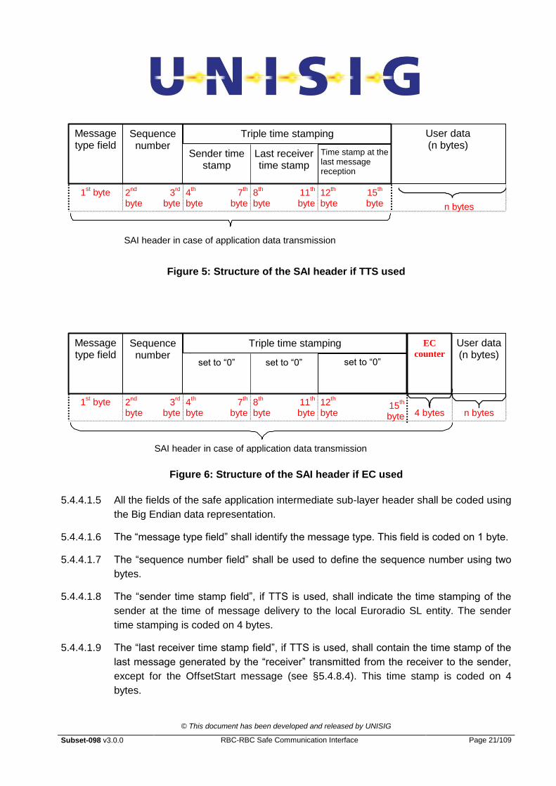
5.4.4.1.4 The structure of the header added by the safe application intermediate sub-layer, in
case of safe data transfer, is the following:
© This document has been developed and released by UNISIG
Subset-098 v3.0.0 RBC-RBC Safe Communication Interface Page 21/109
User data (n bytes)
Message type field
Sender time stamp
1st byte 2
nd
byte 3
rd
byte
4th
byte 11
th
byte 12
th
byte
n bytes
Last receiver time stamp
7th
byte 8
th
byte
SAI header in case of application data transmission
Sequence number
Triple time stamping
Time stamp at the last message reception
15th
byte
Figure 5: Structure of the SAI header if TTS used
User data (n bytes)
Message type field
set to “0”
1st byte 2
nd
byte 3
rd
byte
4th
byte 11
th
byte 12
th
byte
n bytes
set to “0”
7th
byte 8
th
byte
SAI header in case of application data transmission
Sequence number
Triple time stamping
set to “0”
15th
byte
EC
counter
4 bytes
Figure 6: Structure of the SAI header if EC used
5.4.4.1.5 All the fields of the safe application intermediate sub-layer header shall be coded using
the Big Endian data representation.
5.4.4.1.6 The “message type field” shall identify the message type. This field is coded on 1 byte.
5.4.4.1.7 The “sequence number field” shall be used to define the sequence number using two
bytes.
5.4.4.1.8 The “sender time stamp field”, if TTS is used, shall indicate the time stamping of the
sender at the time of message delivery to the local Euroradio SL entity. The sender
time stamping is coded on 4 bytes.
5.4.4.1.9 The “last receiver time stamp field”, if TTS is used, shall contain the time stamp of the
last message generated by the “receiver” transmitted from the receiver to the sender,
except for the OffsetStart message (see §5.4.8.4). This time stamp is coded on 4
bytes.

© This document has been developed and released by UNISIG
Subset-098 v3.0.0 RBC-RBC Safe Communication Interface Page 22/109
5.4.4.1.10 “Time stamp at the last message reception”, if TTS is used, shall indicate the local time
stamp when the last received message is delivered by the local Euroradio SL entity,
except for the OffsetStart message (see §5.4.8.4). This time stamp is coded on 4
bytes.
5.4.4.1.11 The EC counter field shall be used and present in the header only if the EC defence
technique is used.
5.4.4.1.12 The EC counter shall be coded on 4 bytes.
5.4.4.1.13 As the EC and TTS defence techniques shall be mutually exclusive, the fields related
to the TTS defence technique are not checked if the EC defence technique is used.
The value of the “TTS” fields are set to “0”.
5.4.5 SAI Protocol
5.4.5.1 Connection procedure
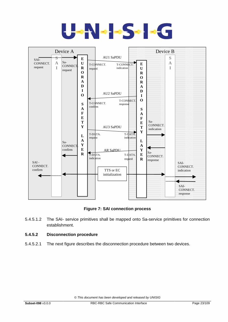
5.4.5.1.1 The next figure represents the connection procedure between two devices.
© This document has been developed and released by UNISIG
Subset-098 v3.0.0 RBC-RBC Safe Communication Interface Page 23/109
S
A
I
S
A
I
E
U
R
O
R
A
D
I
O
S
A
F
E
T
Y
L
A
Y
E
R
E
U
R
O
R
A
D
I
O
S
A
F
E
T
Y
L
A
Y
E
R
AU1 SaPDU
AU2 SaPDU
AU3 SaPDU
AR SaPDU
SAI-
CONNECT.
request
SAI -
CONNECT.
confirm
Sa-
CONNECT.
indication
Sa-
CONNECT.
response
Device A Device B
T-CONNECT.
request T-CONNECT.
indication
T-CONNECT.
response T-CONNECT.
confirm
T-DATA.
request
T-DATA.
request
T-DATA.
indication
T-DATA.
indication
Sa-
CONNECT.
request
Sa-
CONNECT.
confirm
SAI-
CONNECT.
indication
SAI-
CONNECT.
response
TTS or EC
initialization
Figure 7: SAI connection process
5.4.5.1.2 The SAI- service primitives shall be mapped onto Sa-service primitives for connection
establishment.
5.4.5.2 Disconnection procedure
5.4.5.2.1 The next figure describes the disconnection procedure between two devices.

© This document has been developed and released by UNISIG
Subset-098 v3.0.0 RBC-RBC Safe Communication Interface Page 24/109
Figure 8: Disconnection procedure
5.4.5.2.2 The SAI-service primitives shall be mapped onto SA-primitives for disconnection .
5.4.5.3 Procedure for exchange of application data
5.4.5.3.1 For the transmission of application data messages, the following process shall be
applied.
5.4.5.3.2 Using the SAI-DATA.request, the application can send data to the peer entity (see
Subset-037).
5.4.5.3.3 Using the SAI-DATA.request, the SAI sub-layer shall be able to identify the SaCEPID
of the connection.
5.4.5.3.4 The SAI sub-layer shall add, in the SAI header, to the application data:
the message type for the application data exchange;
the sequence number;
the TTS fields. The time stamp shall be set to “0” if the EC defence technique is
used;
the EC counter and version, only if the EC technique is used.
5.4.5.3.5 The SAI sub-layer shall hand over the application data to the Euroradio SL using the
Sa-DATA request primitive, the Sa User data parameter being composed of the
concatenation of the message type, sequence number, the TTS fields and the EC
fields. The EC fields are present only if the EC defence technique is used.

© This document has been developed and released by UNISIG
Subset-098 v3.0.0 RBC-RBC Safe Communication Interface Page 25/109
5.4.5.3.6 For the reception of the application data messages, the following process shall be
applied.
5.4.5.3.7 Using the Sa-DATA.indication, the Euroradio SL can pass data to the application, after
the processing by the SAI layer (see Subset-037).
5.4.5.3.8 The Sa-DATA.indication shall provide the SaCEPID.
5.4.5.3.9 The Sa user data parameter is composed of:
Message type for the application data exchange;
Sequence number;
TTS fields. The time stamp shall be set to “0” if the EC defence technique is used;
EC counter, only if the EC technique is used.
5.4.5.3.10 The Message type field shall be one of the ones defined for the exchange of
application data.
5.4.5.3.11 The SAI shall check the sequence number before the EC counter or TTS.
5.4.5.3.12 If the EC defence technique is used, the TTS fields are not checked and only the EC
fields shall be checked.
5.4.5.3.13 If the TTS defence technique is used, the TTS fields shall be checked.
5.4.5.3.14 If all the checks are performed successfully, the application data and the SaCEPID
shall be passed to the application using the SAI-DATA.indication.
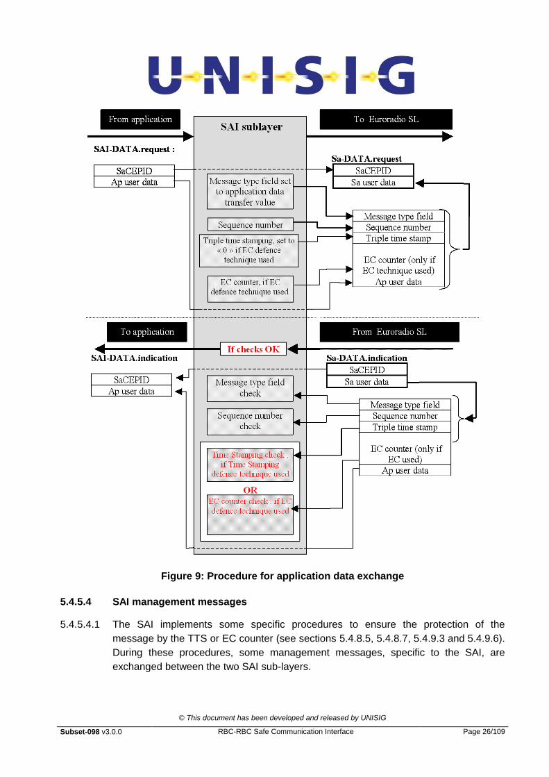
5.4.5.3.15 The following figure illustrates the application data exchange:
© This document has been developed and released by UNISIG
Subset-098 v3.0.0 RBC-RBC Safe Communication Interface Page 26/109
Figure 9: Procedure for application data exchange
5.4.5.4 SAI management messages
5.4.5.4.1 The SAI implements some specific procedures to ensure the protection of the
message by the TTS or EC counter (see sections 5.4.8.5, 5.4.8.7, 5.4.9.3 and 5.4.9.6).
During these procedures, some management messages, specific to the SAI, are
exchanged between the two SAI sub-layers.
© This document has been developed and released by UNISIG
Subset-098 v3.0.0 RBC-RBC Safe Communication Interface Page 27/109
5.4.5.4.2 The SAI management messages are identified by a specific value of the message type
field or by the use of data transfer messages without any application data.
5.4.5.4.3 The SAI management messages shall be exchanged between SAI sub-layers using
the Sa-DATA.request and Sa-DATA.indication primitives.
5.4.5.4.4 The sequence number, EC and TTS fields shall be processed in the same way as the
procedure used for exchange of application data.
5.4.5.4.5 For the message transmission, the value of message type field shall be selected in
relation with the type of management message. Depending on the management
message type, the user data could come from the application layer or be computed by
the SAI itself. If no application data is transmitted to the peer application layer, the SAI
layer shall be able to select the proper SaCEPID for the management message.
5.4.5.4.6 Depending on the type of management message received by the SAI, the user data
will be processed by the SAI itself, accordingly to the message type, or transferred,
with the SaCEPID, to the application as application data.
5.4.6 Message type field
5.4.6.1.1 Ten message types are defined, six for the TTS, four for the EC counter.
5.4.6.1.2 The message types for the TTS defence technique shall be compliant with the
following list:
OffsetStart message (1st message for the clock offset estimation): 1
OffsetAnsw1 message (2nd
message for the clock offset estimation): 2
OffsetAnsw2 message (3rd message for the clock offset estimation): 3
OffsetEst message (4th message for the clock offset estimation): 4
OffsetEnd message (5th message for the clock offset estimation): 5
Application message protected by TTS: 6
5.4.6.1.3 The message types in hexadecimal for the EC defence technique shall be compliant
with the following list:
ExecutionCycleStart message: 81
Application message protected by EC defence technique: 86
Application message, protected by EC, with Request of Acknowledge: 87
Application message, protected by EC, with Acknowledge: 88
© This document has been developed and released by UNISIG
Subset-098 v3.0.0 RBC-RBC Safe Communication Interface Page 28/109
5.4.7 Sequence numbering defence technique
5.4.7.1.1 The sequence number field shall be coded on 2 bytes (big Endian).
5.4.7.1.2 The sequence number has a value from 0 to 65535.
5.4.7.1.3 The sequence numbers shall be independent for each communicating direction.
5.4.7.1.4 There is no requirement for the sequence number initialisation. The receiver shall
accept any sequence number in the first sequence numbered message received from
the peer entity.
5.4.7.1.5 It shall not check that the first sequence number received has a specific value. It has
only to check the sequence number difference with the previous message.
5.4.7.1.6 If the sequence number value is different of the maximum value, the sequence number
shall be incremented by one at each new message transmission in the same direction.
5.4.7.1.7 Once the sequence number value reaches the maximum value, the value of the
sequence number at the next message transmission shall be set to “0”.
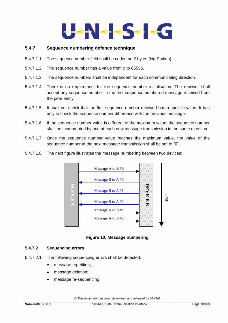
5.4.7.1.8 The next figure illustrates the message numbering between two devices: D
EV
ICE
A
DE
VIC
E B
Message A to B #0
Message A to B #1
Message A to B #2
Message B to A #0
Message B to A #1
Message B to A #2
TIM
E
Figure 10: Message numbering
5.4.7.2 Sequencing errors
5.4.7.2.1 The following sequencing errors shall be detected:
message repetition;
message deletion;
message re-sequencing.
© This document has been developed and released by UNISIG
Subset-098 v3.0.0 RBC-RBC Safe Communication Interface Page 29/109
5.4.7.2.2 In the case of an error being detected, the SAI is not able to take any action to recover
the missing data.
5.4.7.2.3 A parameter N is defined for the message sequence check. N-1 is the number of
missing messages allowed. N has to be configured. The value of N shall be equal or
greater to 1.
5.4.7.2.4 If the received SN is not equal to the SN of the last accepted message + 1 it is treated
as a message sequence error.
5.4.7.2.5 The message shall be discarded and the safe connection shall be released, if the
received SN is greater than the SN of the last accepted message + N.
5.4.7.2.6 If the received SN is greater than the SN of the last accepted message + 1 and less
than or equal to the SN of the accepted message + N, the application data in this
message is not discarded, and this event is handled according to the specified error
handling (see §5.4.10.1.2).
5.4.7.2.7 The message shall be discarded if the received SN is less than or equal to the SN of
the last accepted message.
5.4.7.2.8 The reaction to the sequence number error shall comply with the SAI error handling
procedure (see § 5.4.10).
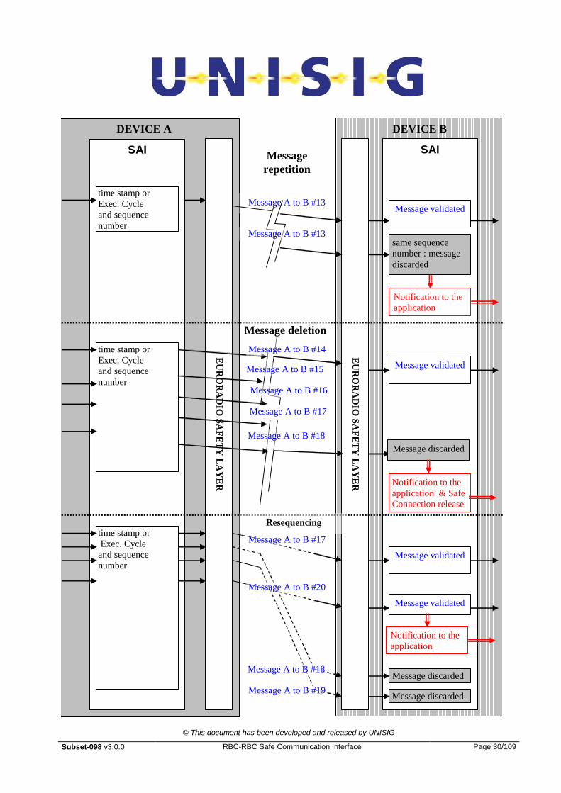
5.4.7.2.9 The next figure illustrates the behaviour of the sequence numbering defence technique
in the case of repeated, deleted or re-sequenced messages, in this case with N=3, that
is, the number of allowed missing messages is 0,1 or 2.
© This document has been developed and released by UNISIG
Subset-098 v3.0.0 RBC-RBC Safe Communication Interface Page 30/109
DEVICE A DEVICE B
EU
RO
RA
DIO
SA
FE
TY
LA
YE
R
EU
RO
RA
DIO
SA
FE
TY
LA
YE
R
SAI SAI
Message A to B #13 Message validated
same sequence
number : message
discarded
Message
repetition
time stamp or
Exec. Cycle
and sequence
number
time stamp or
Exec. Cycle
and sequence
number
Message A to B #13
Message A to B #14
Message A to B #15
Message A to B #16
Message A to B #18
Message validated
Message discarded
Message deletion
time stamp or
Exec. Cycle
and sequence
number
Resequencing
Message validated
Message validated
Message discarded
Message discarded
Message A to B #17
Message A to B #18
Message A to B #19
Message A to B #20
Notification to the
application
Notification to the
application & Safe
Connection release
Notification to the
application
Message A to B #17

© This document has been developed and released by UNISIG
Subset-098 v3.0.0 RBC-RBC Safe Communication Interface Page 31/109
Figure 11: Sequencing errors
5.4.8 Triple Time Stamping
5.4.8.1 Introduction
5.4.8.1.1 This time stamping procedure is based on the clock-offset estimation between the
sender and the receiver. The clock-offset estimation shall be initiated after the safe
connection establishment and before the application data exchange.
5.4.8.1.2 The knowledge of the clock offset between the two devices allows them to estimate, in
a safe way, the time validity of the application data, without making any assumption
about the remote device temporal cycle and/or the network characteristics.
5.4.8.1.3 The time stamping tuning procedure (clock offset update procedure) consists of the
exchange of five messages between the two devices. Using this procedure, each
device shall estimate the clock offset between its internal clock and the one of the peer
device.
5.4.8.1.4 All the application messages shall be time stamped using a triple time stamp.
5.4.8.1.5 The second and third time stamps are used, only to compute and update the clock
offset estimation. The first is used for the clock-offset estimation and update, but also
to compute the time validity of the application data.
5.4.8.1.6 On receipt of a message, the receiver shall adapt the sender transmission time stamp
to the receiver clock using the clock offset estimation and then compute the validity
time of the application data.
5.4.8.1.7 It is a matter for the receiver sub-system to manage the “zero crossing” of the time
stamp information coming from the sender.
5.4.8.1.8 Periodically, the estimation of the clock offset between the two devices shall be
updated using the “Clock offset update” procedure.
5.4.8.2 Time stamping format
5.4.8.2.1 The time stamping shall be big-endian, coded on 32 bits. The time stamping format
shall be the same as the one defined for the EVC-RBC communication (see T_TRAIN
definition in Subset-026-7).
5.4.8.2.2 The least significant bit time value is equal to 10 ms.
5.4.8.3 Clock offset estimation principles
© This document has been developed and released by UNISIG
Subset-098 v3.0.0 RBC-RBC Safe Communication Interface Page 32/109
5.4.8.3.1 The knowledge of the clock offset allows a device to estimate the time validity of
messages exchanged between itself and another device.
5.4.8.3.2 The clock-offset estimation is done at the safe connection initialisation. The clock
offset update procedure shall be performed before the exchange of the first application
message.
5.4.8.3.3 The device that initiates the safe connection shall start the clock offset update
procedure.
5.4.8.3.4 The clock-offset estimation consists in the exchange of 5 messages between the two
entities. The entity initiating the clock offset update procedure is called the “initiator”,
and the other, the “responder” entity.
5.4.8.3.5 Using the first two messages, the initiator device shall compute a maximum and a
minimum clock offset between the two devices.
5.4.8.3.6 Using the second and third messages, the responder device shall compute the
maximum and minimum clock offset between the two devices.
5.4.8.3.7 The fourth and fifth messages are used for the validation of the clock offset
estimations.
5.4.8.4 Clock offset update messages
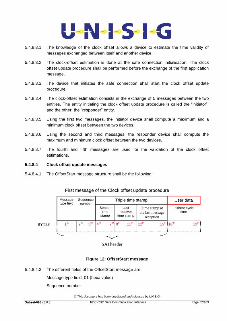
5.4.8.4.1 The OffsetStart message structure shall be the following:
First message of the Clock offset update procedure
Message type field
Sender time
stamp
7th
Last receiver
time stamp
1st
SAI header
Sequence number
Triple time stamp
Initiator cycle time
BYTES 2nd
3rd
4th 8
th 11
th 12
th 15
th 16
th 19
th
Time stamp at
the last message
reception
User data (n bytes)
Figure 12: OffsetStart message
5.4.8.4.2 The different fields of the OffsetStart message are:
Message type field: 01 (hexa value)
Sequence number
© This document has been developed and released by UNISIG
Subset-098 v3.0.0 RBC-RBC Safe Communication Interface Page 33/109
Sender time stamp: This field defines the time stamp of the clock offset estimation
initiator.
Last received time stamp: This field gives usually the last time stamp transmitted from
the responder to the initiator. As there is no previous time stamp value given by the
“responder, the value is set to “0”.
Time stamp at the last message reception: This field usually gives the time value at the
last message reception from the responder. As there is no previous application
message from the responder, this field is set to “0”.
Initiator cycle time: This field gives optionally the message transmission cycle in case
of systems using cyclic transmission from the initiator to the responder. If the message
transmission is non-cyclic, the value is set to “0”. The “Initiator cycle time” uses the
same format and time resolution as the time stamp field.
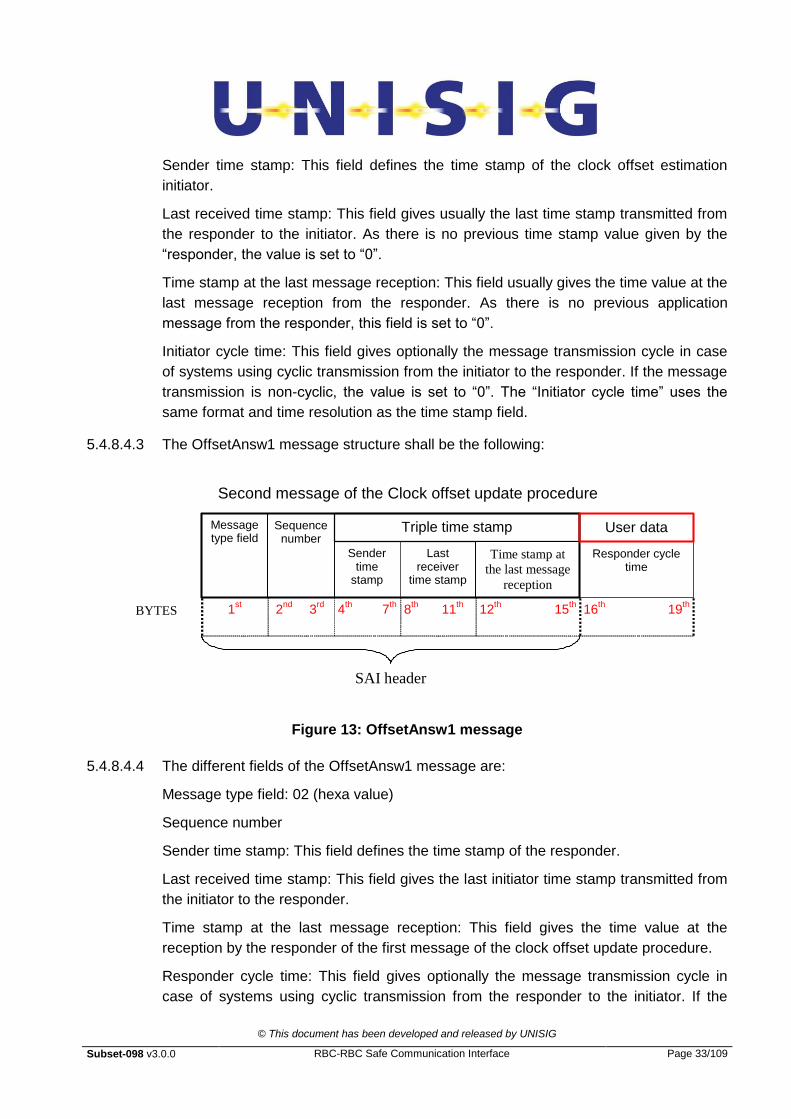
5.4.8.4.3 The OffsetAnsw1 message structure shall be the following:
Second message of the Clock offset update procedure
Message type field
Sender time
stamp
7th
Last receiver
time stamp
1st
SAI header
Sequence number
Triple time stamp
Responder cycle time
BYTES 2nd
3rd
4th 8
th 11
th 12
th 15
th 16
th 19
th
Time stamp at
the last message
reception
User data (n bytes)
Figure 13: OffsetAnsw1 message
5.4.8.4.4 The different fields of the OffsetAnsw1 message are:
Message type field: 02 (hexa value)
Sequence number
Sender time stamp: This field defines the time stamp of the responder.
Last received time stamp: This field gives the last initiator time stamp transmitted from
the initiator to the responder.
Time stamp at the last message reception: This field gives the time value at the
reception by the responder of the first message of the clock offset update procedure.
Responder cycle time: This field gives optionally the message transmission cycle in
case of systems using cyclic transmission from the responder to the initiator. If the
© This document has been developed and released by UNISIG
Subset-098 v3.0.0 RBC-RBC Safe Communication Interface Page 34/109
message transmission is non-cyclic, the value is set to “0”. The responder cycle time
uses the same format and time resolution as the time stamp field.
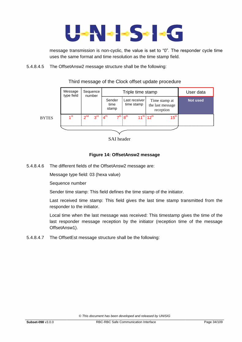
5.4.8.4.5 The OffsetAnsw2 message structure shall be the following:
Third message of the Clock offset update procedure
Message type field
Sender time
stamp
7th
Last receiver time stamp
1st
SAI header
Sequence number
Triple time stamp
Not used
BYTES 2nd
3rd
4th 8
th 11
th
User data (n bytes)
Time stamp at
the last message
reception
12th 15
th
Figure 14: OffsetAnsw2 message
5.4.8.4.6 The different fields of the OffsetAnsw2 message are:
Message type field: 03 (hexa value)
Sequence number
Sender time stamp: This field defines the time stamp of the initiator.
Last received time stamp: This field gives the last time stamp transmitted from the
responder to the initiator.
Local time when the last message was received: This timestamp gives the time of the
last responder message reception by the initiator (reception time of the message
OffsetAnsw1).
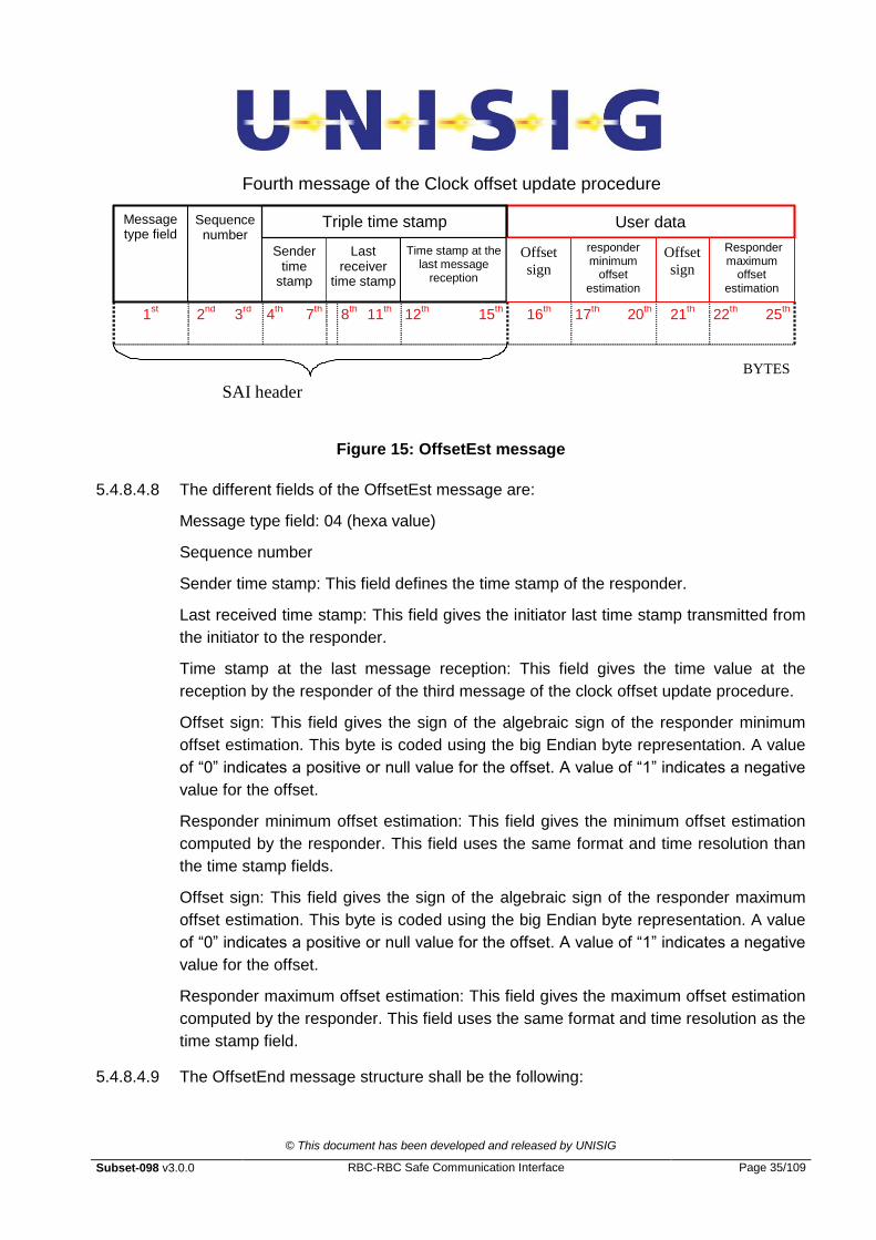
5.4.8.4.7 The OffsetEst message structure shall be the following:
© This document has been developed and released by UNISIG
Subset-098 v3.0.0 RBC-RBC Safe Communication Interface Page 35/109
Fourth message of the Clock offset update procedure
User data (n bytes)
Message type field
Sender time
stamp
7th
Last receiver
time stamp
1st
SAI header
Sequence number
Triple time stamp
responder minimum
offset estimation
Responder maximum
offset estimation
BYTES
2nd
3rd
4th 8
th 11
th 16
th 20
th 21
th 25
th
Time stamp at the last message
reception
12th 15
th
Offset
sign
Offset
sign
17th 22
th
Figure 15: OffsetEst message
5.4.8.4.8 The different fields of the OffsetEst message are:
Message type field: 04 (hexa value)
Sequence number
Sender time stamp: This field defines the time stamp of the responder.
Last received time stamp: This field gives the initiator last time stamp transmitted from
the initiator to the responder.
Time stamp at the last message reception: This field gives the time value at the
reception by the responder of the third message of the clock offset update procedure.
Offset sign: This field gives the sign of the algebraic sign of the responder minimum
offset estimation. This byte is coded using the big Endian byte representation. A value
of “0” indicates a positive or null value for the offset. A value of “1” indicates a negative
value for the offset.
Responder minimum offset estimation: This field gives the minimum offset estimation
computed by the responder. This field uses the same format and time resolution than
the time stamp fields.
Offset sign: This field gives the sign of the algebraic sign of the responder maximum
offset estimation. This byte is coded using the big Endian byte representation. A value
of “0” indicates a positive or null value for the offset. A value of “1” indicates a negative
value for the offset.
Responder maximum offset estimation: This field gives the maximum offset estimation
computed by the responder. This field uses the same format and time resolution as the
time stamp field.
5.4.8.4.9 The OffsetEnd message structure shall be the following:

© This document has been developed and released by UNISIG
Subset-098 v3.0.0 RBC-RBC Safe Communication Interface Page 36/109
Fifth message of the Clock offset update procedure
User data Message type field
Sender time
stamp
7th
Last receiver
time stamp
SAI header
Sequence number
Triple time stamp
Check field
BYTES 2nd
3rd
4th 8
th 11
th 16
th
Time stamp at the last message
reception
1st 12
th 15
th
Figure 16: OffsetEnd message
5.4.8.4.10 The different fields of OffsetEnd message are:
Message type field: 05 (hexa value)
Sequence number
Sender time stamp: This field defines the time stamp of the responder.
Last received time stamp: This field gives the last responder time stamp transmitted
from the responder to the initiator.
Time stamp at the last message reception: This timestamp gives the time of the last
responder message reception by the initiator (reception time of the message
OffsetEst).
Check field: This field gives the result of the clock offset estimation checks. If the clock
offset estimation comparison is validated, the check field value is set to “1”. In case of
non-validation, the check field value is set to “0”.
5.4.8.5 Clock offset update procedure
5.4.8.5.1 The next figure specifies the clock offset update procedure:

© This document has been developed and released by UNISIG
Subset-098 v3.0.0 RBC-RBC Safe Communication Interface Page 37/109

© This document has been developed and released by UNISIG
Subset-098 v3.0.0 RBC-RBC Safe Communication Interface Page 38/109
Figure 17: Clock offset update procedure
5.4.8.5.2 The initiator shall begin the clock offset update procedure by sending the OffsetStart
message.
5.4.8.5.3 The initiator starts the Tinit_start timer at the OffsetStart message transmission. If the
initiator does not receive the OffsetAnsw message at the Tinit_start timer expiration, the
error shall be managed using the error handling procedure (see §5.4.10).
5.4.8.5.4 At the OffsetStart message reception, the responder shall answer sending the
OffsetAnsw message.
5.4.8.5.5 At the OffsetAnsw message transmission, the responder starts a timer: Tres_start. If the
OffsetAnsw2 message is not received at the timer expiration, the error shall be
managed using the error handling procedure (see §5.4.10).
5.4.8.5.6 If the initiator receives the OffsetAnsw message before the Tinit_start expiration, the
initiator shall estimate the maximum and minimum offsets between the clocks of the
initiator and the responder.
5.4.8.5.7 Then the initiator sends the message OffsetAnsw2 to the responder. At the
OffsetAnswer2 transmission, the initiator starts the Tinit_start timer. If the initiator does not
receive the OffsetEst message at the Tinit_start timer expiration, the error shall be
managed using the error handling procedure (see §5.4.10 ).
5.4.8.5.8 If the responder receives the OffsetAnsw2 message before the Tres_start expiration, the
responder shall estimate the maximum and minimum offsets between the clocks of the
initiator and the responder.
5.4.8.5.9 Then the responder sends the message OffsetEst to the initiator. At the OffsetEst
transmission, the responder starts the Tres_start timer. If the responder does not catch
the OffsetEnd message at the Tres_start timer expiration, the error shall be managed
using the error handling procedure (see §5.4.10 ).
5.4.8.5.10 If the initiator catches the OffsetEst message before the expiration of the Tinit_start timer,
the initiator shall check the maximum and minimum offset estimations made
respectively by the initiator and the responder. Then the initiator sends, using the
Offset End message, the result of the offset check to the responder. In case of failure
of the check, the error shall be managed using the error handling procedure (see
§5.4.10 ).
5.4.8.5.11 At the OffsetEnd message reception, the responder shall take into account the clock
offset estimation result. In case of failure of the check, the error shall be managed
using the error handling procedure (see §5.4.10 ).
5.4.8.5.12 In case of the validation of the clock-offset estimations and cyclic message
transmission in one or both directions, an optional TTS cyclic timer could be activated.

© This document has been developed and released by UNISIG
Subset-098 v3.0.0 RBC-RBC Safe Communication Interface Page 39/109
This timer is not safety related and is used only to detect, at an early stage, missing
cyclic messages.
5.4.8.5.13 The optional TTS cyclic timer is reset at each message reception. If no message is
caught at the timer elapsing, the error shall be managed using the error handling
procedure (see §5.4.10).
5.4.8.6 Time stamp procedure and check
5.4.8.6.1 The message used to transfer application data between application layers shall be
compliant with the following figure:
Message between application layer
User data Message type field
Sender time
stamp
7th
Last receiver
time stamp
1st
SAI header
Sequence number
Triple time stamp
User data
BYTES 2nd
3rd
4th 8
th 11
th
Time stamp at the last message
reception
12th 15
th
Figure 18: Application data message
5.4.8.6.2 The different type fields are:
Message type field: 6 (hexa value)
Sequence number
Sender time stamp: This field defines the time stamp of the sender.
Last received time stamp: This field gives the last time stamp transmitted from the
receiver to the sender.
Time stamp at the last message reception: This timestamp gives the time of the
last message reception from the pair entity
User data: User data field.
5.4.8.6.3 The time stamp principles consist of:
Put the sender's own time stamp in the sender time stamp field.
Put the last time stamp received from the receiver in the last received time stamp field.
Put the sender time stamp at the last message reception from the receiver in the Time
stamp at the last message reception field.
5.4.8.6.4 It is a matter for the receiver sub-system to manage the zero crossing of the time
stamp information coming from the sender.

© This document has been developed and released by UNISIG
Subset-098 v3.0.0 RBC-RBC Safe Communication Interface Page 40/109
5.4.8.6.5 The next figure illustrates the triple time stamping principle:
Figure 19: Triple time stamp principle
5.4.8.6.6 In case of a mistake in the time stamp procedure, the error shall be managed using the
error handling procedure (see §5.4.10).
5.4.8.6.7 After the Clock offset update procedure, the maximum and minimum clock offsets are
fixed and the time validity of the data application messages can be estimated.
5.4.8.6.8 The messages sent by the sender devices shall be time stamped using the sender
clock, the last time stamp received from the peer entity and the time stamp of the
reception of the last message coming from the peer entity.
5.4.8.6.9 When the receiver device receives the application data message, the sending time of
the message shall be estimated in terms of the receiver clock, using the minimum
clock offset estimation done by the receiver and the extra processing delay estimation.
This estimation is given by the next expression:
Treceiver = Ttime_stamp_sender - Textra_delay + Trec_offset_min.
© This document has been developed and released by UNISIG
Subset-098 v3.0.0 RBC-RBC Safe Communication Interface Page 41/109
5.4.8.6.10 The difference between the sending time estimated in terms of the receiver clock and
the message reception time by the receiver device (Trec_current-Treceiver) allows to estimate
the freshness of the message.
5.4.8.6.11 The delay of the message is acceptable if the difference result assures the time validity
of the data transmitted. The time validity is defined by a value Tmax. This parameter is a
configuration variable agreed between the both peers. In case of non-tolerable delay,
the message is rejected and the error has to be managed using the error handling
procedure (see §5.4.10).
5.4.8.6.12 The Tmax parameter corresponds with the maximum validity time of the data coming
from the pair entity.
5.4.8.6.13 The Tmax value allows detection of an increase of the transmission time and a positive
temporal drift between the two device clocks.
5.4.8.6.14 Obviously, the difference result (Trec_current - Treceiver) has to be positive. If the result is
negative, the error shall be managed using the error handling procedure (see §5.4.10).
5.4.8.6.15 The next figure describes the time validity check procedure. The following
abbreviations are used:
Ttime_stamp_sender: transmission sender time stamp (sender time stamp field in the time
stamp message structure.
Treceiver: estimation of the application data time transmission in terms of receiver clock.
Textra_delay: total sum of the extra delays due to the processing time of the application
data in the sender sub-system.
Trec_offset_min: minimum clock offset estimation done by the receiver.
Tmax,: maximum validity time.
Trec_current: current time of the receiver at the message reception.
Tinit: time of the application data transmission in terms of sender clock.

© This document has been developed and released by UNISIG
Subset-098 v3.0.0 RBC-RBC Safe Communication Interface Page 42/109
Sender device
Receiver device
Ttime_stamp_sender
TreceiverTrec_current
Legend :
Treceiver : estimation of the application data time transmission in terms of receiver clock.
Tinit : time of the application data transmission in terms of sender clock
Ttime_stamp_sender : transmission sender time stamp
Trec_current : current time of the receiver at the message reception
Tmax : maximum validity time
Textra_delay : total sum of the extra delays due to the processing time of the application data in the
sender sub-system.
Trec_offset_min : minimum clock offset estimation done by the receiver
Textra_delay : optional
Extra delay
Treceiver is the Tinit estimation using the receiver
device clock : Treceiver = Ttime_stamp_sender -
Textra_delay + Trec_offset_min
The message is valid if :
0 Trec_current - Treceiver Tmax
Tinit over-estimation due to the computation
in safety of Trec_offset_min and Textra_delay
Tinit
Lower boundary
corresponding to
Tmax
Allowed time window for the
Treceiver computation result
Figure 20: Time stamping computation
5.4.8.7 Clock offset update update
5.4.8.7.1 The clock offset update procedure shall be performed at least periodically according to
a configured value.
5.4.8.7.2 The next figure specifies the clock offset update procedure:
© This document has been developed and released by UNISIG
Subset-098 v3.0.0 RBC-RBC Safe Communication Interface Page 43/109
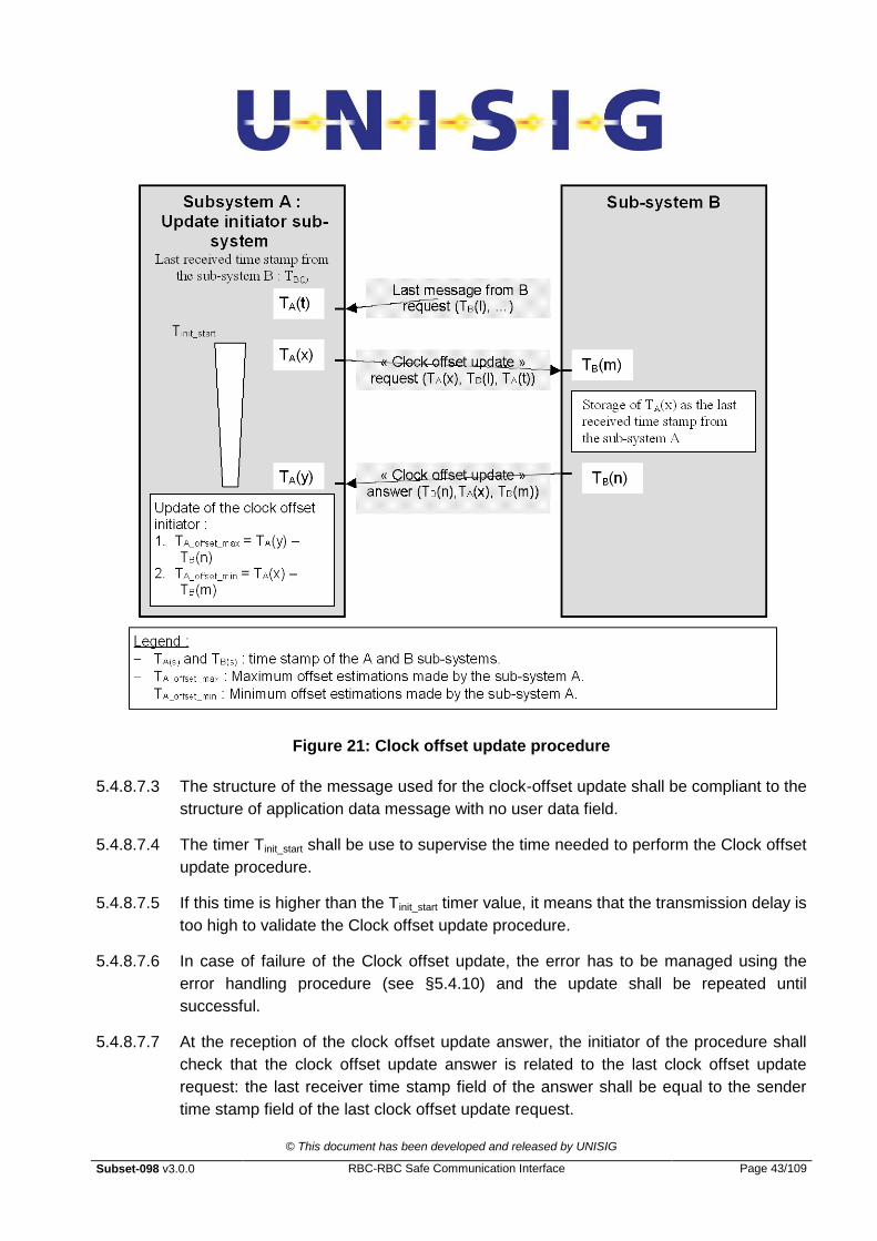
Figure 21: Clock offset update procedure
5.4.8.7.3 The structure of the message used for the clock-offset update shall be compliant to the
structure of application data message with no user data field.
5.4.8.7.4 The timer Tinit_start shall be use to supervise the time needed to perform the Clock offset
update procedure.
5.4.8.7.5 If this time is higher than the Tinit_start timer value, it means that the transmission delay is
too high to validate the Clock offset update procedure.
5.4.8.7.6 In case of failure of the Clock offset update, the error has to be managed using the
error handling procedure (see §5.4.10) and the update shall be repeated until
successful.
5.4.8.7.7 At the reception of the clock offset update answer, the initiator of the procedure shall
check that the clock offset update answer is related to the last clock offset update
request: the last receiver time stamp field of the answer shall be equal to the sender
time stamp field of the last clock offset update request.

© This document has been developed and released by UNISIG
Subset-098 v3.0.0 RBC-RBC Safe Communication Interface Page 44/109
5.4.9 EC defence technique
5.4.9.1 General overview
5.4.9.1.1 The EC defence technique is used to protect the application data message against the
delay threat, as required by EN 50159-2, and to ensure the time validity of the
application data.
5.4.9.1.2 The protection against the delay threat is achieved by using the EC counter contained
in the Header of each message received from the peer entity.
5.4.9.1.3 The EC shall have a fixed period.
5.4.9.1.4 The detection of the delay threat is achieved by making a comparison between the EC
counter contained in the message received from the peer entity and the expected EC
counter in that receiver EC.
5.4.9.1.5 This defence technique consists in guaranteeing in transmission the availability of a
message (without application data, if not required by the application) within a certain
time period starting from last transmitted message, therefore turning the transmission
mode into pseudo-cyclic. So at the other side of the safe connection, it is possible to
manage a timeout on the data receiving.
5.4.9.2 Format of EC counter
5.4.9.2.1 The EC counter shall be big Endian coded on 32 bits.
5.4.9.2.2 The EC counter has a value from 0 to 4294967295.
5.4.9.2.3 For each direction, the EC counter shall be independent.
5.4.9.2.4 There is no requirement for EC counter initialisation. The receiver shall accept any EC
counter value in the first EC counter received from the peer entity in the
ExecutionCycleStart message.
5.4.9.2.5 If the EC counter value is different from the maximum value, the EC counter shall be
incremented by one at each EC of the sender.
5.4.9.2.6 Once the EC counter value reaches the maximum value, the value of the sequence
number at the next EC shall be set to 0.
5.4.9.2.7 The handling of the Sequence Number shall be independent from the handling of the
EC Counter in both the sender and the receiver subsystems.
5.4.9.3 Initialisation procedure of the EC defence technique

© This document has been developed and released by UNISIG
Subset-098 v3.0.0 RBC-RBC Safe Communication Interface Page 45/109
5.4.9.3.1 Once the safe connection between the Euroradio SL‟s of the two entities has been
established, two messages are exchanged between the two safe application
intermediate sub-layers in order to exchange the parameters needed for the EC
defence technique.
5.4.9.3.2 The following figure illustrates the initialisation procedure:
Figure 22: Initialisation phase of the EC defence technique
5.4.9.3.3 Once the safe connection has been established between the two entities using the
AU1, AU2, AU3 and AR SaPDU‟s, the entity that initiated the safe connection shall
send an ExecutionCycleStart message to the peer entity with its initial EC counter and
its EC period.
5.4.9.3.4 The peer entity shall answer with an ExecutionCycleStart message containing its own
information (initial EC counter and EC period).
5.4.9.3.5 After the reception of the ExecutionCycleStart from the remote, the initiator entity can
start sending its Application Messages, and shall apply the EC Defence Technique.
The responder entity can start sending its Application Messages on the next cycle after
the forward of the ExecutionCycleStart to the initiator entity.

© This document has been developed and released by UNISIG
Subset-098 v3.0.0 RBC-RBC Safe Communication Interface Page 46/109
5.4.9.3.6 A timer (Tsyn) shall be implemented in each peer entity in order to detect unacceptable
initial delays:
In the SAI of the connection initiator entity: the timer is set at the sending of the
ExecutionCycleStart message and is stopped at the reception of the
ExecutionCycleStart message from the responder;
In the SAI of the connection responder entity: the timer is set at the sending of the
ExecutionCycleStart message and is stopped at the reception of the first DT SaPDU
by the counterpart SAI, containing the first Application Message.
5.4.9.3.7 If a timer expires before the reception of the expected message, the error has to be
managed using the error handling procedure (see 5.4.10).
5.4.9.3.8 The ExecutionCycleStart message structure shall be compliant with the following
figure:
User dataMessage
type field
1st byte 2
nd
byte3
rd
byte4
th
byte
« Elaborationcycle » period
« safe application interface » header in case ofapplication data transmission
Sequence
number
Triple timestamping :Not used
15th
byte
Elaborationcycle
number :initial value
16th
byte19
th
byte20
th
byte23
th
byte
Version
24th
byte25
th
byte
Figure 23: ExecutionCycleStart message
5.4.9.3.9 The EC period shall be coded, Big Endian, on two bytes. The EC period has a value
from 0 to 65535. The least significant bit time value is equal to 1 msec (resolution is 1
msec).
5.4.9.3.10 The Version field shall be coded Big Endian on four bytes. The Version field can be
used to verify the consistency of the versions of the local and remote SAI software.
5.4.9.4 EC counter check procedure
5.4.9.4.1 Once the initialisation procedure of the EC defence technique has been successfully
achieved, each entity shall check if the application data transmitted by the peer entity
is obsolete or not.
5.4.9.4.2 This defence technique is based on the evaluation of the value of the EC Counter
contained in the messages received by the remote subsystem, which is compared with
the expected one (Ex).
© This document has been developed and released by UNISIG
Subset-098 v3.0.0 RBC-RBC Safe Communication Interface Page 47/109
5.4.9.4.3 The first step of the EC defence technique consists in defining the expected EC
Counter. For the computation of the expected EC value, the ratio R between the local
and the remote EC period shall be computed by each SAI entity at the end of the
initialisation of the EC defence technique1 using the following formula:
R = receiver EC period / sender EC period.
Note: R is a real number.
5.4.9.4.4 At each EC of the receiver, the expected EC value (Ex) to be used in the next EC shall
be updated using the following formula:
Next Ex = (Ex value of the current cycle) + R
Note: Ex is a real number 2 .
5.4.9.4.5 The current state is computed at the end of each receiver EC and depends only on the
integer variable Delta which is computed using the following formula:
Delta = lower integer value of (Ex - EC Counter contained in the last message received
from the remote entity in that EC).
5.4.9.4.6 If no message arrives to the receiver in an EC, the receiver shall compute Delta (and
consequently the new state) using the EC counter of the last message received in the
previous cycles. When more than one application messages are received in an EC, the
last EC counter value received shall be used.
5.4.9.4.7 The state transition diagram defined by the following figure shall be applied by the SAI
receiver at each EC. If Delta is greater or equal to the Alarm State (e.g. 3 in the case
described by the following figure), an alarm shall be issued and the error has to be
managed using the error handling procedure (see §5.4.10). In the following example
that means the EC counter of the last message received from the peer entity is at least
3 sender cycles older than the expected EC counter. If the Delta value is greater or
equal to the alarm state, all the messages received during the cycle have to be
discarded.
5.4.9.4.8 When the initiator receives the EC Start message from the responder, the initiator shall
initialise the Ex using the EC counter value contained in that message and, in the
same EC, update it using the formula in §5.4.9.4.43.
1 The ratio R can be also set and fixed as an equipment configuration parameter. The choice of dynamic or
static setting of the R parameter must be fixed and agreed between the two parties before the equipment
start up. 2 R and Ex are real numbers, while the EC periods and EC numbers are integers.
3 If more Application Data Messages are received in this cycle after the EC Start, the EC contained in the last
message is used to update the Next Ex
© This document has been developed and released by UNISIG
Subset-098 v3.0.0 RBC-RBC Safe Communication Interface Page 48/109
5.4.9.4.9 When the responder receives the first Application Data message from the initiator, the
responder shall initialise the Ex using the EC counter value contained in that message
received from the initiator and, in the same EC, update it using the formula in
§5.4.9.4.44.
4 If more Application Data Messages are received in this cycle, the EC contained in the last message is used
to update the Next Ex
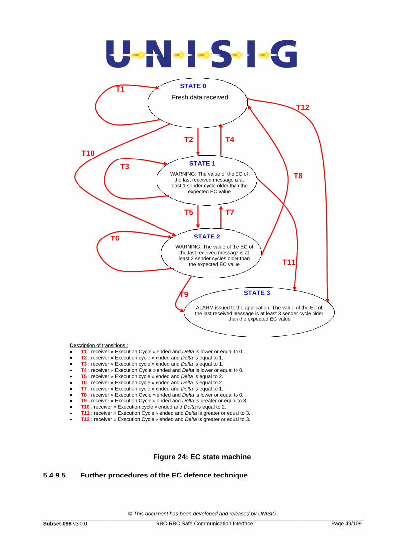
© This document has been developed and released by UNISIG
Subset-098 v3.0.0 RBC-RBC Safe Communication Interface Page 49/109
Fresh data received
STATE 0 T1
WARNING: The value of the EC of the last received message is at
least 1 sender cycle older than the expected EC value
STATE 1
T2 T4
T3
WARNING: The value of the EC of the last received message is at least 2 sender cycles older than
the expected EC value
STATE 2 T6
T5 T7
T8
ALARM issued to the application: The value of the EC of the last received message is at least 3 sender cycle older
than the expected EC value
STATE 3 T9
Description of transitions :
T1 : receiver « Execution Cycle » ended and Delta is lower or equal to 0.
T2 : receiver « Execution cycle » ended and Delta is equal to 1.
T3 : receiver « Execution cycle » ended and Delta is equal to 1.
T4 : receiver « Execution Cycle » ended and Delta is lower or equal to 0.
T5 : receiver « Execution cycle » ended and Delta is equal to 2.
T6 : receiver « Execution cycle » ended and Delta is equal to 2.
T7 : receiver « Execution cycle » ended and Delta is equal to 1.
T8 : receiver « Execution Cycle » ended and Delta is lower or equal to 0.
T9 : receiver « Execution Cycle » ended and Delta is greater or equal to 3.
T10 : receiver « Execution cycle » ended and Delta is equal to 2.
T11 : receiver « Execution Cycle » ended and Delta is greater or equal to 3.
T12 : receiver « Execution Cycle » ended and Delta is greater or equal to 3.
T10
T11
T12
Figure 24: EC state machine
5.4.9.5 Further procedures of the EC defence technique
© This document has been developed and released by UNISIG
Subset-098 v3.0.0 RBC-RBC Safe Communication Interface Page 50/109
5.4.9.5.1 Both the effects of long term drift of the clock and the error caused by approximation of
the EC cycle 5
may result in a very slow change of the EC period (with respect to the
official value stated in the EC Start message) and so in an error of R (with respect to
the value computed at the end of the initialisation phase). This can lead, in a long
period, to the receiving of:
More messages than the expected, because the sender Subsystem is faster than
the expected (or the receiver Subsystem is slower: the result is the same): this
results in undue staying in the “pseudo-state –1” for a long time, then in the
“pseudo-state –2” and so on (all these pseudo-states are grouped in the state 0,
because the data arrived are fresh). In such states the EC counter check base
procedure could not promptly detect real delays.
Less messages than the expected, even in case there is no message delay,
because the sender Subsystem is slower than the expected (or the receiver
Subsystem is faster: the result is the same): this results in undue staying in the
state 1 of the State Machine for a long time, then in the state 2 and so on reaching
the Alarm state.
5.4.9.5.2 The following action shall be applied by the SAI, in order to correct the effects
described above:
If Delta is lower or equal to a (negative) value (configuration parameter) i.e. more
messages are received than the expected (when an entity receives the EC start
message from the peer entity, only this message is expected within the current cycle of
the receiver), the expected EC counter (Ex) shall be updated using the EC Counter
contained in the last message received from the peer entity:
Next Ex = (last EC value received in the current cycle) + R
If the State Machine remains in the same state (different from the state 0) for a very
long period (the number of cycles being a configuration parameter), it is forced to
going back to the upper state (1 => 0, 2 => 1) by decrementing the value of the
expected EC counter (Ex). The Procedure for Detection of transmission delay shall be
executed in this case6.
5.4.9.6 Procedure for Detection of transmission delay
5.4.9.6.1 Because staying in the same state for a very long time could be due to other problems
in the transmission chain7, like slowly increasing delay, not only to approximation of R,
5 a permanent error of some tens of ppm is to be expected for the clock source (clock accuracy)
6 this procedure can be executed immediately before or immediately after the forcing to the upper state, this
choice being a local implementation matter. 7 by “transmission chain” it is intended in this document all the transmission equipment and network elements
between the two peer safe entities.
© This document has been developed and released by UNISIG
Subset-098 v3.0.0 RBC-RBC Safe Communication Interface Page 51/109
the corrective actions defined in §5.4.9.5 could hide these real delays: a further
mechanism is provided to detect them.
5.4.9.6.2 Both the initiator subsystem and the responder one that wants to detect a possible
transmission delay, shall send an “Application Message with request of ACK” to the
peer entity, which has exactly the same format as the normal Application Message but
a different message type (0x87 instead of 0x86). Note that this is a normal Data
ApPDU containing the user data to be sent to the peer entity8.
5.4.9.6.3 At the reception of the “Application Message with request of ACK”, the Subsystem
shall answer to the peer entity sending in the next cycle an “Application Message with
ACK” which has exactly the same format as the normal Application Message but a
different message type (0x88). Note that this is a normal Data ApPDU containing the
user data to be sent to the peer entity9.
5.4.9.6.4 A timer (Tsyn) shall be implemented in the Subsystem that sends the “Application
Message with request of ACK” in order to provide a further detection of unacceptable
transmission delays: the timer is set at the sending of the “Application Message with
request of ACK” and is stopped at the reception of the “Application Message with ACK”
from the peer entity.
5.4.9.6.5 If the timer expires before the reception of the expected message the error has to be
managed using the error handling procedure (see 5.4.10).
5.4.9.6.6 This delay detection procedure is equal to that used during the initialisation procedure
of the EC defence technique (initial delay detection), but using the Application
Message instead of the EC Start message. This procedure is described by the
following figure (where one requesting entity only is shown).
8 The Application Message flow and processing is not affected by this mechanism.
9 The Application Message flow and processing is not affected by this mechanism.
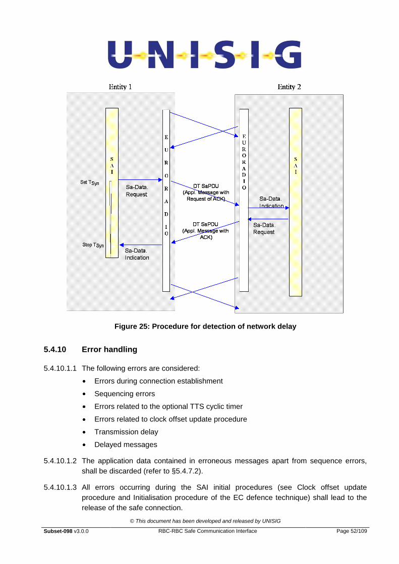
© This document has been developed and released by UNISIG
Subset-098 v3.0.0 RBC-RBC Safe Communication Interface Page 52/109
Figure 25: Procedure for detection of network delay
5.4.10 Error handling
5.4.10.1.1 The following errors are considered:
Errors during connection establishment
Sequencing errors
Errors related to the optional TTS cyclic timer
Errors related to clock offset update procedure
Transmission delay
Delayed messages
5.4.10.1.2 The application data contained in erroneous messages apart from sequence errors,
shall be discarded (refer to §5.4.7.2).
5.4.10.1.3 All errors occurring during the SAI initial procedures (see Clock offset update
procedure and Initialisation procedure of the EC defence technique) shall lead to the
release of the safe connection.

© This document has been developed and released by UNISIG
Subset-098 v3.0.0 RBC-RBC Safe Communication Interface Page 53/109
5.4.10.1.4 For sequencing errors, errors related to the optional TTS cyclic timer, and errors
related to the clock offset update procedure, transmission delay and delayed
messages, the safe connection shall be released after a configurable number of
successive errors (Tsucc_er).
5.4.10.1.5 In case of failure of the clock offset update procedure or of the procedure for detection
of transmission delay, an independent error counter shall be used and the procedure
shall be repeated without delay.
5.4.10.1.6 In the EC technique, the connection shall be released if the Delta value reaches the
Alarm State.
5.4.10.1.7 Note: The location of error handling (e.g. application, SAI, error handler) is a matter of
the implementation. A notification for the error handling outside the SAI can be given.
5.5 Configuration data and rules
5.5.1 Introduction
5.5.1.1.1 This section provides rules for the connection establishment and informative guideline
to fix SFM parameters.
5.5.2 Connection initiation rules
5.5.2.1 General overview
5.5.2.1.1 To establish the connection between two trackside devices, some rules have to be
defined to settle precisely which device has to initiate the connection.
5.5.2.1.2 The co-existence of different track equipment types on the network requires a
definition of priority rules for the connection initiation between the different track
devices.
5.5.2.1.3 Each trackside equipment shall know the ETCS-ID type and ETCS-ID of each other
trackside equipments to which a communication channel is established.
5.5.2.2 Connection initiation principle
5.5.2.2.1 Each device of the network has two tables:
Table of passive connections
Table of active connections
5.5.2.2.2 The Table of passive connections contains the ETCS-ID list of the devices from which
the device has to wait for a connection request.

© This document has been developed and released by UNISIG
Subset-098 v3.0.0 RBC-RBC Safe Communication Interface Page 54/109
5.5.2.2.3 Any incoming connection from remote entity which is not in the table of passive
connections shall be rejected.
5.5.2.2.4 The Table of active connections contains the ETCS-ID list of the devices to which the
device has to initiate the connection.
5.5.2.2.5 During the start-up procedure or after connection loss, the device begins to try to
connect the other device listed in the Table of active connections.
5.5.2.2.6 If the connection to a device included in the Table of active connections is not
established during the trackside equipment initialisation, the device shall try to connect
periodically to the peer equipment.
5.5.2.2.7 The usual rule is to define the tables of passive and active connections in such way
that the connection is initiated by the device switched on last.
5.5.3 Guideline for TTS parameter definition
5.5.3.1 Tmax value
5.5.3.1.1 The Tmax value is a system parameter, it is the maximum validity time of the application
data transferred between the two RBCs.
5.5.3.1.2 This parameter could depend for example on the following factors:
Track layout
Performance requirements
RBC implementation
System rules
5.5.3.2 Textra_delay
5.5.3.2.1 The Textra_delay parameter could be used to take into account the time between the
generation of the application data and the time stamping of the message at the SAI
level.
5.5.3.2.2 The default value of this parameter is “0”.
5.5.3.3 Tinit_start and Tres_start
5.5.3.3.1 The value of these timers should be equal to the maximum time allowed to have an
answer to a request.
5.5.3.3.2 A way to fix the timer value is to use the following rule (margin expressed in %):
Time value = (1+margin/100) * (2* maximum transmission time +
maximum time between request reading by the RBC and answer transmission)
© This document has been developed and released by UNISIG
Subset-098 v3.0.0 RBC-RBC Safe Communication Interface Page 55/109
Note: The transmission time should take into account:
the maximum network transmission time
the time between the time stamping of the message and the sending of this one on
the network
the time requested by the receiver to read the message
5.5.3.4 Toff_max
5.5.3.4.1 The value of this timer should be equal to the maximum acceptable transmission time
between the two devices.
Note: The transmission time should take into account:
the maximum network transmission time
the time between the time stamping of the message and the sending of this one on
the network
the time requested by the receiver to read the message
5.5.3.5 Optional TTS cyclic timer
5.5.3.5.1 The value of optional timer for cyclic message could be estimated using the following
rule:
Optional TTS cyclic timer = cycle of the peer RBC +
maximum allowed transmission time
Note: The transmission time should take into account:
the maximum network transmission time;
the time between the time stamping of the message and the sending of this one on
the network;
the time requested by the receiver to read the message.
5.5.3.6 Cycle for clock offset update
5.5.3.6.1 The clock offset update is used to prevent natural clock drift.
5.5.3.6.2 For each a time accuracy parameter is provided: let Pr%.
5.5.3.6.3 For a system, the maximum tolerance on the clock drift could be defined: let X sec.
5.5.3.6.4 The cycle for clock offset update could be computed using the following formula (with a
margin of Y%):
Cycle (sec) = (100*X sec /Pr) /(1+Y/100)
5.5.3.6.5 For example: Pr = 0,1 , Y = 100% and X = 0,5 sec Cycle = 250 sec
© This document has been developed and released by UNISIG
Subset-098 v3.0.0 RBC-RBC Safe Communication Interface Page 56/109
5.5.4 Guideline for EC parameter definition
5.5.4.1 Tsyn
5.5.4.1.1 The value of this timer should be equal to the maximum time allowed to have an
answer to a request.
5.5.4.1.2 A way to fix the timer value is to use the following rule (margin expressed in %):
Time value = (1+margin/100) * ( 2* maximum transmission time +
maximum time between request reading by the RBC and answer transmission)
Note: The transmission time should take into account:
the maximum network transmission time;
the time between the time stamping of the message and the sending of this one on
the network;
the time requested by the receiver to read and process the message and produce
the required answer.
5.5.4.2 Alarm state
5.5.4.2.1 The “Alarm State” value is a system parameter. This parameter scales the maximum
validity time of the application data transferred between the two RBCs.
5.5.4.2.2 This parameter could depend for example on the following factors:
Track layout;
Performance requirements;
RBC implementation;
System rules.
5.5.4.3 Version
5.5.4.3.1 Only one version value is presently defined: 01 (hexadecimal).
5.5.4.4 Procedure for Detection of transmission delay
5.5.4.4.1 The procedure for detection of transmission delay should be repeated cyclically.
5.5.4.4.2 The cycle should be fixed using an approach similar to the one used for the definition
of the optional TTS cyclic timer.
5.5.5 Guideline for error handling
5.5.5.1 Parameter N
5.5.5.1.1 If no missing messages are allowed then N should be set to 1.
© This document has been developed and released by UNISIG
Subset-098 v3.0.0 RBC-RBC Safe Communication Interface Page 57/109
5.5.5.1.2 N has to be agreed for a specific project and for each connection.
5.5.5.1.3 If RBC‟s with different N are to be connected together the more restrictive value for N
should be used for this connection in both RBC‟s.
5.5.5.2 Parameter Tsucc_er
5.5.5.2.1 If class D is used in the ALE layer and is implemented on at least two independent
physical links, the application data are sent twice using independent routes to the peer
SAI. As in this case an error at the SAI level results from a major disturbance on the
two physical links, a release of the connection at the first error is recommended: Tsucc_er
= 1.
5.5.5.2.2 In the other configurations (class A and class D on one physical link), the application
data are exchanged between the two entities on only one physical link. As in this case
a single disturbance on this link could lead to an error in the receiving SAI, a release of
the connection after two successive errors is recommended: Tsucc_er = 2. If a highly-
available network is used, the value of Tsucc_er value could be set to “1”
5.6 TTS examples
5.6.1.1.1 The following figures illustrate the TTS technique:

© This document has been developed and released by UNISIG
Subset-098 v3.0.0 RBC-RBC Safe Communication Interface Page 58/109

© This document has been developed and released by UNISIG
Subset-098 v3.0.0 RBC-RBC Safe Communication Interface Page 59/109
Figure 26: Example of Clock offset update procedure

© This document has been developed and released by UNISIG
Subset-098 v3.0.0 RBC-RBC Safe Communication Interface Page 60/109
FOR DEVICE A as receiver :
FOR DEVICE B as receiver :
Validity time (Tmax) = 300. ΔTextra_delay = 0
Tinit = 4863
Transmission time = 43
Trec_current = 4863 + 850 +43 + 32 = 5788
Treceiver = 4863 -0+829 = 5692
0<= 5788 - 5692 <= 300
0<= 96 <= 300
Sender = device B
Receiver = device A
Validity time (Tmax) = 300. ΔTextra_delay = 0
Tinit = 12250
Transmission time = 48
Trec_current = 12250-850+48+25 =11473
Treceiver = 12250 -0+(-863) = 11387
0<= 11473-11387<= 300
0<= 86 <= 300
Sender = device A
Receiver = device B
Margin to take into
account the message

© This document has been developed and released by UNISIG
Subset-098 v3.0.0 RBC-RBC Safe Communication Interface Page 61/109
Figure 27: Example of Time stamp procedure and check

© This document has been developed and released by UNISIG
Subset-098 v3.0.0 RBC-RBC Safe Communication Interface Page 62/109
6. COMMUNICATION FUNCTIONAL MODULE
6.1 General
6.1.1.1.1 This part of the present document specifies the communication protocols used by the
CFM in the RBC-RBC Safe Communication Interface.
6.1.1.1.2 This part of the specification does not define:
the content and structure of information messages which are exchanged between
components of an implementation;
any implementation details concerning the interface itself;
the open networks used;
the physical architecture of the CFM.
6.1.1.1.3 This section describes only the functional interface requirements to be respected to
ensure interworking at the level of the transport and network protocols. It must not be
understood as a proposal to implement a particular software architecture.
6.2 Overview
6.2.1 General description
6.2.1.1.1 In this specification of the CFM both end systems are assumed fixed (i.e. not mobile), it
is assumed that they can be attached to industry standard high-speed networks. This
specification defines the use of Euroradio Transport Layer primitives to access
redundant services running over TCP. It provides a method of communicating between
ERTMS equipment using international standards and without the need for
manufacturers to know the proprietary details of each other‟s system.
6.2.1.1.2 The general features of the CFM are as follows:
Reliable full-duplex transfer of railway application messages;
Transparent transfer of user data. The content, format or coding of the information
is not to be restricted. Interpretation of the data structure or its meaning is not
needed to achieve data transfer;
No constraints on user data, that is the protocol shall in no way constrain the type
of data to be transferred;
Efficient data transfer, the CFM shall support well defined performance
requirements including the transfer of large quantities of data at high speeds and
with low latency;

© This document has been developed and released by UNISIG
Subset-098 v3.0.0 RBC-RBC Safe Communication Interface Page 63/109
Open to different known and currently unknown applications.
Support of physical link redundancy for availability purposes
6.3 Functional Characteristics
6.3.1 TCP equivalence to Transport Class 2 service and protocol
6.3.1.1.1 This specification is targeted at applications running on ground based systems
operated by different suppliers. It is therefore required that these services are provided
by taking advantage of industry standard TCP/IP solutions rather than the alternative
protocols offered by OSI or CENELEC standards. Hence in this specification TCP is
adopted to provide a reliable connection orientated service instead of ISO TP2. Any
known limitations that this approach imposes are described in this document.
6.3.1.1.2 The aim of mandating these requirements is to ensure that flexible, high availability,
high-speed and cost effective COTS solutions can be used to link the end systems so
reducing cost and lead times.
6.3.1.1.3 The mapping between the Transport Class 2 service and TCP shall be as described in
this specification, using the Adaptation Layer Entity (ALE). This entity shall transfer
data between peers in discrete variable length packets named ALE packets
(ALEPKTs).
6.3.1.1.4 The following diagram outlines the protocol stacks used to connect an ERTMS
application to its counterpart (in this example via intermediate wide area network
routed links).
IP IP IP IP
LLC1 LLC1
MAC HDLC HDLC MAC
802.3u G.703 G.703 802.3u
Peer 1 Peer 2Optional Router Optional Router
802.3u
Application
SAI
Euroradio Safety Layer
TCP
IP
LLC1
Adaptation of X.214 service over TCP
Media Access Control (MAC)
802.3u
Application
SAI
Media Access Control (MAC)
Euroradio Safety Layer
TCP
IP
LLC1
Adaptation of X.214 service over TCP
Routing Routing

© This document has been developed and released by UNISIG
Subset-098 v3.0.0 RBC-RBC Safe Communication Interface Page 64/109
Figure 28: Protocol stacks used to connect an ERTMS application to its counterpart
Note: the shaded areas imply bespoke software, the white areas contain an example of a possible
implementation
6.3.1.1.5 The diagram shows the relationship of the various components to one another. The
applications responsible for providing the functionality required shall make use of the
standard Euroradio Safety Protocol primitives. The Safety Protocol will access the
communications sub-layers via a functional interface relevant to the environment. This
will access an emulation of the ISO transport service using the standard primitives.
6.3.1.1.6 This service will actually be provided using TCP/IP as the underlying transport and
network layers rather than using the ISO TP2 and T.70 that are defined in Euroradio
protocols for communication between RBCs and OBUs.
6.3.1.1.7 The example diagram above shows typical IP routers being used to interconnect
systems over a wide area link.
6.3.2 Class of Service
6.3.2.1.1 In order to be generically applicable there must be options to vary the quality of service
requested and offered by peers. To increase availability of the service defined in this
document there are a number of ways in which independently routed TCP connections
may be used to support a single logical connection between peer applications (whether
safe or non-safe).
6.3.2.1.2 A set of different qualities of service, known to the ALE as „Class of Service‟ are
specified. These are characterised as follows:
Class A – Two links are normally used. Either of two links can be used to transfer
data. All ALEPKTs are transmitted on one link only. (Typically both links shall have
equal performance)
Class D – Two links are normally used with all ALEPKTs transmitted on both links.
6.3.2.1.3 The implementation of Class D is mandatory, while the implementation of Class A is
optional.
6.3.2.1.4 Implementations with one physical link are supported by the protocols.
6.3.2.1.5 Both Class A and D can operate with one single physical link only, without any impact
on the safety.
6.3.2.1.6 The Class of Service used at each end of a connection shall be the same.

© This document has been developed and released by UNISIG
Subset-098 v3.0.0 RBC-RBC Safe Communication Interface Page 65/109
6.3.3 Class A request
6.3.3.1.1 A request for a Class A quality of service shall result in the Adaptation Layer
attempting to make two TCP connections to the remote Adaptation Layer entity. The
nominated primary connection shall be that which is used initially to transfer data. The
secondary connection shall be opened, maintained and monitored by the Adaptation
Layer entity but shall not be used to transfer data unless the primary route is deemed
to have failed. The exact details of how these links shall be monitored and managed
are contained in §6.6.
6.3.3.1.2 The definition of TCP/IP address details are contained within the Adaptation Layer and
are selected based on the ETCS-ids and Application Type details that are contained in
the primitive T-Connect.Request.
6.3.4 Class D request
6.3.4.1.1 A request for a Class D quality of service shall result in the Adaptation Layer
attempting to make two TCP connections to the remote Adaptation Layer entity. Both
connections shall be used to transfer all data and control messages. The safe
connection shall continue to operate on one link in the event of a failure of the other.
The exact details of how these links shall be monitored and managed are contained in
§6.6.
6.3.4.1.2 A request for class D connection can be also accepted for one TCP connection over
one physical link.
6.3.4.1.3 The definition of TCP/IP address details are contained within the Adaptation Layer and
are selected based on the ETCS-ids and Application Type details that are contained in
the primitive T-Connect.Request.
6.3.5 Relationship between TS-User and TCP
6.3.5.1.1 The diagram in Figure 29 shows the relationship between a TS-User and two TCP
channels.
6.3.5.1.2 A Safe Application may use the equivalent access primitives (at the ApSAP) to access
the Safe Application Intermediate Sub-layer. These are the same primitives that the
Euroradio Safety Layer supports (at the SASAP) .
6.3.5.1.3 The Euroradio Safety Layer completes message protection and transmits the message
to the CFM in Safety Protocol Data Units (SaPDUs) through service access primitives
at TSAPs providing an ISO Transport service.
6.3.5.1.4 Some mapping of functions is required in the Adaptation Layer in order to permit the
use of TCP protocol instead of an ISO Transport Class 2 protocol.
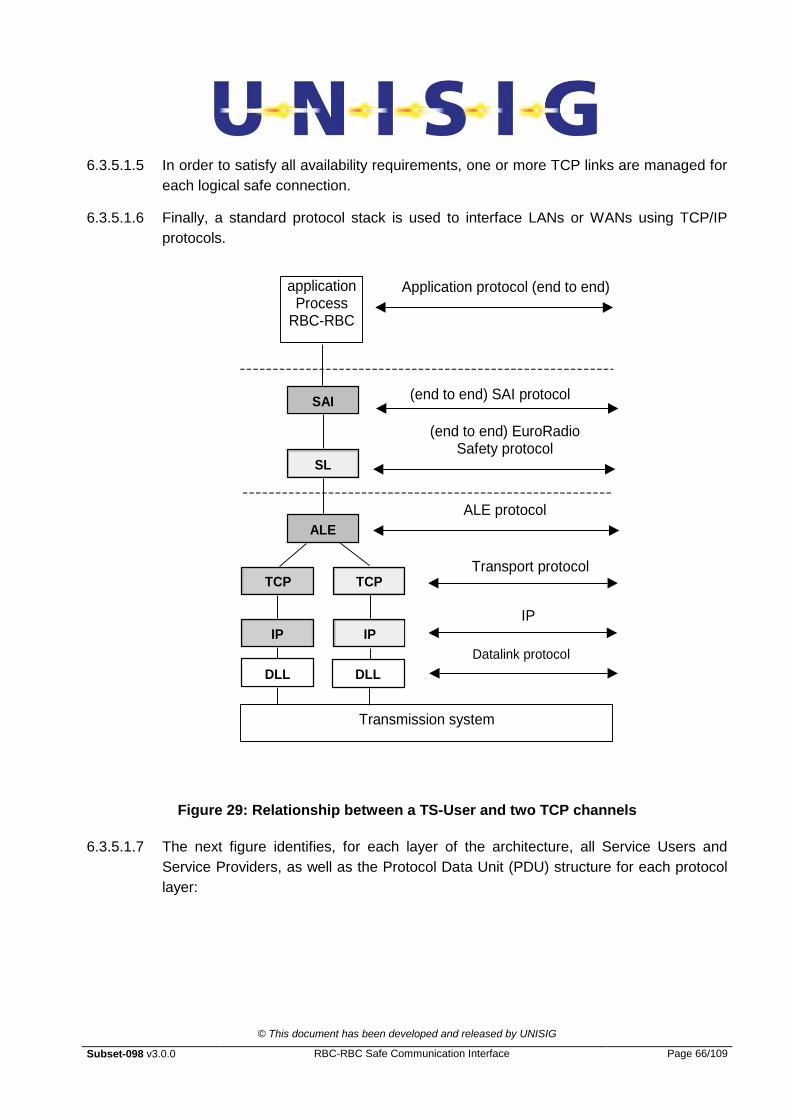
© This document has been developed and released by UNISIG
Subset-098 v3.0.0 RBC-RBC Safe Communication Interface Page 66/109
6.3.5.1.5 In order to satisfy all availability requirements, one or more TCP links are managed for
each logical safe connection.
6.3.5.1.6 Finally, a standard protocol stack is used to interface LANs or WANs using TCP/IP
protocols.
(end to end) EuroRadio Safety protocol
Application protocol (end to end) application Process
RBC-RBC
ALE protocol
Transport protocol (TCP)
(end to end) SAI protocol
IP
Transmission system
SAI
SL
ALE
TCP
IP
DLL
TCP
IP
DLL
Datalink protocol
Figure 29: Relationship between a TS-User and two TCP channels
6.3.5.1.7 The next figure identifies, for each layer of the architecture, all Service Users and
Service Providers, as well as the Protocol Data Unit (PDU) structure for each protocol
layer:

© This document has been developed and released by UNISIG
Subset-098 v3.0.0 RBC-RBC Safe Communication Interface Page 67/109
Figure 30: Reference message structure
6.3.6 Transport Priorities
6.3.6.1.1 In Subset-037, Transport priorities are related to Application type as follows:
0 = Not used
1 = ATP.
6.3.6.1.2 Transport priorities are not available nor supported over TCP.
6.4 Transport Layer Emulation using an Adaptation Layer Entity
6.4.1 General Overview
6.4.1.1.1 This section contains the functional requirements of the transport service provided by
the CFM module.
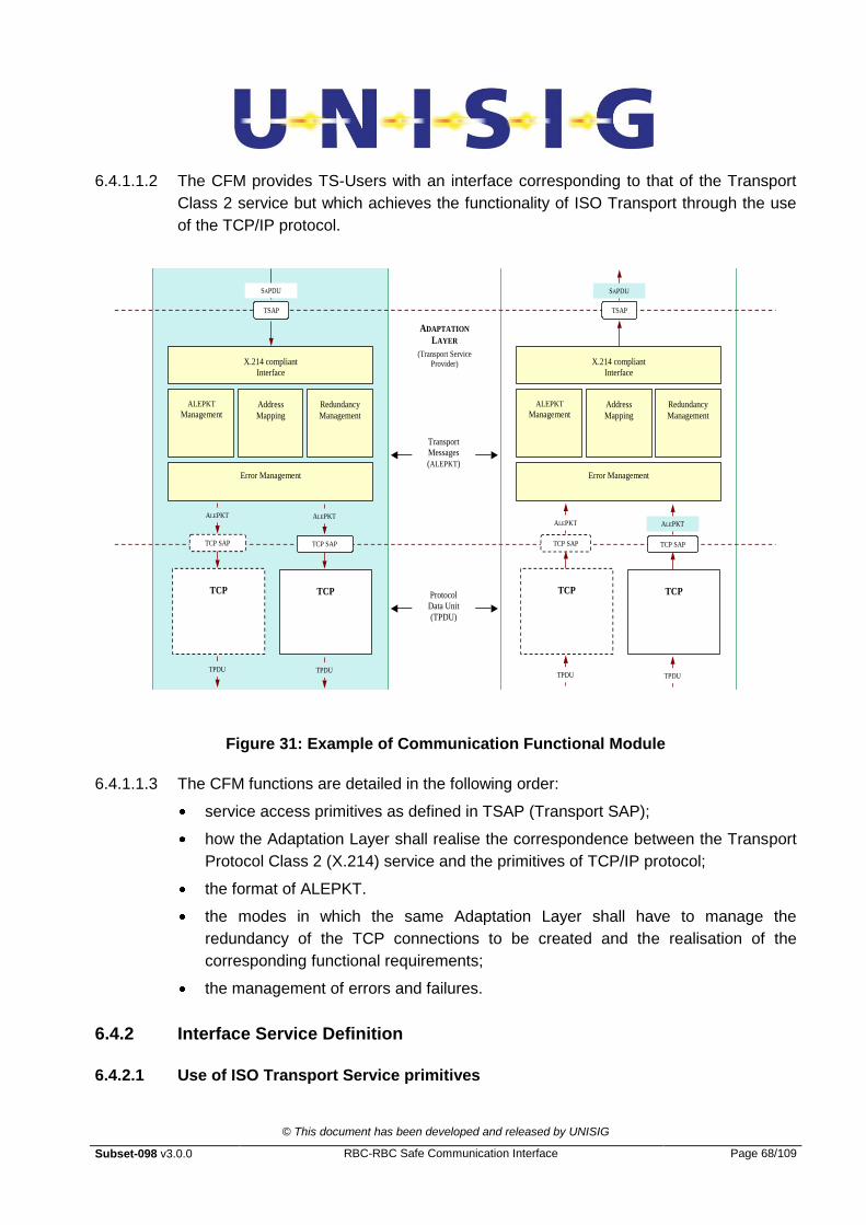
© This document has been developed and released by UNISIG
Subset-098 v3.0.0 RBC-RBC Safe Communication Interface Page 68/109
6.4.1.1.2 The CFM provides TS-Users with an interface corresponding to that of the Transport
Class 2 service but which achieves the functionality of ISO Transport through the use
of the TCP/IP protocol.
TCP
TPDU
Protocol
Data Unit
(TPDU)
TPDU
TCP
SAPDU
TSAP
SAPDU
TSAP
TCP SAP
ALEPKT
TCP SAP
ALEPKT
Transport
Messages
(ALEPKT)
ADAPTATION
LAYER
(Transport Service Provider)
TCP
TPDU TPDU
TCP
TCP SAP
ALEPKT
TCP SAP
ALEPKT
Error Management
X.214 compliant
Interface
ALEPKT
Management Address
Mapping
Redundancy
Management
Error Management
X.214 compliant
Interface
ALEPKT
Management Address
Mapping
Redundancy
Management
Figure 31: Example of Communication Functional Module
6.4.1.1.3 The CFM functions are detailed in the following order:
service access primitives as defined in TSAP (Transport SAP);
how the Adaptation Layer shall realise the correspondence between the Transport
Protocol Class 2 (X.214) service and the primitives of TCP/IP protocol;
the format of ALEPKT.
the modes in which the same Adaptation Layer shall have to manage the
redundancy of the TCP connections to be created and the realisation of the
corresponding functional requirements;
the management of errors and failures.
6.4.2 Interface Service Definition
6.4.2.1 Use of ISO Transport Service primitives
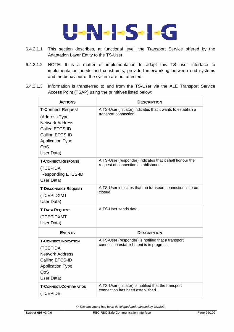
© This document has been developed and released by UNISIG
Subset-098 v3.0.0 RBC-RBC Safe Communication Interface Page 69/109
6.4.2.1.1 This section describes, at functional level, the Transport Service offered by the
Adaptation Layer Entity to the TS-User.
6.4.2.1.2 NOTE: It is a matter of implementation to adapt this TS user interface to
implementation needs and constraints, provided interworking between end systems
and the behaviour of the system are not affected.
6.4.2.1.3 Information is transferred to and from the TS-User via the ALE Transport Service
Access Point (TSAP) using the primitives listed below:
ACTIONS DESCRIPTION
T-Connect.Request
(Address Type
Network Address
Called ETCS-ID
Calling ETCS-ID
Application Type
QoS
User Data)
A TS-User (initiator) indicates that it wants to establish a transport connection.
T-CONNECT.RESPONSE
(TCEPIDA
Responding ETCS-ID
User Data)
A TS-User (responder) indicates that it shall honour the request of connection establishment.
T-DISCONNECT.REQUEST
(TCEPIDXMT
User Data)
A TS-User indicates that the transport connection is to be closed.
T-DATA.REQUEST
(TCEPIDXMT
User Data)
A TS-User sends data.
EVENTS DESCRIPTION
T-CONNECT.INDICATION
(TCEPIDA
Network Address
Calling ETCS-ID
Application Type
QoS
User Data)
A TS-User (responder) is notified that a transport connection establishment is in progress.
T-CONNECT.CONFIRMATION
(TCEPIDB
A TS-User (initiator) is notified that the transport connection has been established.

© This document has been developed and released by UNISIG
Subset-098 v3.0.0 RBC-RBC Safe Communication Interface Page 70/109
Responding ETCS-ID
User Data)
T-DISCONNECT.INDICATION
(TCEPIDRCV
Reason
User Data)
A TS-User is notified that the transport connection is closed.
T-DATA.INDICATION
(TCEPIDRCV
User Data)
A TS-User is notified that data can be read from the transport connection.
Table 4: Service primitives in TSAP
6.4.2.1.4 The use of these Transport Service primitives [X.214] shall be supported with the
following modifications:
The Mobile Network ID parameter is meaningless in this context, it shall not be
used.
Expedited Data is not present and shall be not supported by this interface.
Transport Quality of Service parameters (re-defined as Class of Service) are
supported.
Access to Non-disruptive Transport Disconnection shall be provided
6.4.2.1.5 Parameter values used in the X.214 service are compliant with the FIS [Subset-037],
with the following extensions.
6.4.2.1.6 TCEPID: (Transport Connection End Point Identifier) is provided locally to distinguish
between different transport connections. This shall have a mapping to a local TCP port
id. Normally this shall be the TCP Local_Connection_Name
6.4.2.1.7 ETCS Address Type: qualifies the usage of sub-parameters of called address.
6.4.2.1.8 Network Address: If provided, identifies the 32-bit destination IP network address and
the 16-bit destination TCP port number of the called user.
6.4.2.1.9 When the Network Address is supplied by the Safety Layer Entity it shall be used.
Otherwise the other parameters provided shall be used by the Adaptation Layer entity
to retrieve the relevant IP port and TCP address information and hence to establish a
connection to the relevant remote entity.
6.4.2.1.10 Called ETCS-ID: identifies (together with the application type) the called Transport
Service user.
6.4.2.1.11 Calling ETCS-ID: identifies (together with the application type) the Transport
connection initiator.

© This document has been developed and released by UNISIG
Subset-098 v3.0.0 RBC-RBC Safe Communication Interface Page 71/109
6.4.2.1.12 Application Type: As detailed in Subset-037, the first 5 bits of the Application Type
field specify the main application type. The minor Application Type (3 bits) specifies the
main application types in more detail.
6.4.2.1.13 Responding ETCS-ID: identifies (together with the application type) the
accepting/responding Transport Service user that was locally selected by the
responding transport entity.
6.4.2.1.14 Class of Service: is associated with a set of parameter values. The Class of Service
parameters shall not be negotiated. The requested Class of Service parameter values
have to be accepted by the service provider and the peer application. Otherwise the
connection establishment has to be rejected. The Class of Service is independent of
the application type.
6.4.2.1.15 User Data: contains the SaPDUs as required by the Euroradio FIS.
6.4.2.1.16 The tables that follow describe how the primitives can be mapped by the Adaptation
Layer.
6.4.3 Mapping of X.214 primitives to TCP
6.4.3.1.1 Note: This section is for information only. Implementations of TCP which use different
primitives are permissible, provided that there is no impact on interworking.
6.4.3.1.2 The tables that follow summarise how the ISO Transport Class 2 primitives
(actions/events) can be mapped by the Adaptation Layer to TCP/IP protocol:
Actions X.214 Primitives TCP ALE packet type sent
T-Connect.Request TCP_OPEN_PORT TCP_SEND_DATA (AU1 ALEPKT) or TCP_ACTIVE_OPEN_WITH_DATA
(AU1 ALEPKT)
1
T-Connect.Response TCP_SEND_DATA (AU2 ALEPKT) 2
T-Disconnect.Request TCP_Send_Data (DI ALEPKT) (wait) TCP_Close
4
T-Data.Request TCP_Send_ Data (DT ALEPKT) 3
(none) TCP_Read_Data
(none) TCP_Listen_On_Port
(none) TCP_STATUS
(none) TCP_Abort
Events X.214 Primitives TCP ALE packet type received

© This document has been developed and released by UNISIG
Subset-098 v3.0.0 RBC-RBC Safe Communication Interface Page 72/109
T-Connect.Indication TCP_Connected TCP_Data_Ready TCP_Read_Data (AU1 ALEPKT)
1
T-Connect.Confirmation TCP_Connected TCP_Data_Ready TCP_Read_Data (AU2 ALEPKT)
2
T-Disconnect.Indication (after a rejected TCP_Open_Port) TCP_Connect_Fails
(after a TCP_Abort) TCP_Errored
TCP_Data_Ready TCP_Read_Data (DI ALEPKT) TCP_Close TCP_Closed
4
T-Data.Indication TCP_Data_Ready TCP_Read_Data (DT ALEPKT)
3
Table 5: Mapping of X.214 primitives to TCP
6.4.4 Addressing
6.4.4.1 Address Structure
6.4.4.1.1 The Euroradio FIS uses the ETCS-ID address information provided in the primitives to
create transport selectors in the T-Connect.Request TPDU (CR TPDU) and the T-
Connect.Confirm TPDU (CC TPDU). The full address information can be provided in
the primitive parameters as described above.
6.4.4.1.2 When used in TCP/IP connections, this information supplied shall be used by the
Adaptation Layer entity to retrieve the relevant port and IP address information and
hence to establish a connection to the relevant remote entity.
6.4.4.1.3 The first 5 bits of the Application Type field specify the main application type. The
minor application type (3 bits) specifies the main application types in more detail.
§6.5.2 describes how this is transferred to the remote system. The Application Type of
the calling and called peers shall be the same on both peers for a specific connection.
The sender shall use the proper Application Type, the receiver can ignore it.
6.4.4.1.4 To preserve commonality with the Euroradio service provided over ISO Transport the
format of the Application Type parameter used by the Adaptation Layer shall remain
unchanged. The format and the values applicable are specified in Subset-037
§8.2.4.6.4.
6.4.5 Adaptation Layer Packet Format (ALEPKT)
6.4.5.1.1 One of the fundamental differences between the TCP and the ISO Transport Service is
that the TCP manages a continuous stream of octets, with no explicit boundaries
whereas TP2 handles well-bounded TPDUs.

© This document has been developed and released by UNISIG
Subset-098 v3.0.0 RBC-RBC Safe Communication Interface Page 73/109
6.4.5.1.2 To accommodate this difference, the Adaptation Layer uses a simple packetisation
scheme in order to delimit information exchanged by TS-Users.
6.4.5.1.3 On receipt, an ALE is able to re-assemble each information packet previously
embedded in the continuous stream of bytes coming from the TCP level.
6.4.5.1.4 The packets handled by the ALE are called ALEPKTs and are described below as an
object of variable length composed of an integral number of octets. Unless otherwise
stated, all fields are held in Big Endian byte order. An ALEPKT consists of two parts:
a Packet Header
a TS-User Data PDU (User Data).
6.4.5.1.5 The format of the Packet Header is constant:
Packet Length
Version Application type
TSequence Number
N/R Flag
Packet Type
Checksum User Data
<2 octets> <1 octet> <1 octet> <2 octets> <1 octet> <1 octet> <2 octets> < variable length>
where:
Field Name Length Description
Packet Length 2 octets Length of the entire ALEPKT in octets, excluding this 2-octets Packet Length field.
Version 1 octet Used to identify the facilities offered by the Adaptation Layer to other parties. To be agreed between peer entities as part of the configuration.
The Version parameter in ALEPKT may be ignored by the receiving ALE.
Application type
1 octet Identifies application type, as specified in §6.4.4.1
The Application Type parameter in ALEPKT may be ignored by the receiving ALE.
T-Sequence Number
2 octets Transport Sequence Number is used by the receiving Adaptation Layer to manage switching between two active TCP connections.
The T-Sequence number field is not used for the class A.
In this class, the value of the T-Sequence number is set to “0”.
N/R Flag 1 octet Used by the sending ALE to specify the normal or the redundant links on which the ALEPKTs are sent.
The attribution of “normal” and “redundant” to the links is fixed during the configuration phase.
The links shall be connected normal-normal and redundant-redundant.
N= 1; R=0
Packet Type 1 octet Description of the Type of Packet (used by Adaptation Layer to take appropriate action on receipt).
A received ALEPKT containing a Packet Type not specified for the selected class of service shall cause the ALE to discard this packet. The receiving ALE may also close this TCP connection.
Checksum 2 octets Checksum calculated (on the previous 6 fields totalling 8 bytes) as an FCS-16 used to identify if characters have been lost. The

© This document has been developed and released by UNISIG
Subset-098 v3.0.0 RBC-RBC Safe Communication Interface Page 74/109
generator polynomial shall be CRC-CCITT (x16
+x12
+x5+1).The
Cyclic Redundancy Check (CRC) algorithm is specified in ISO/IEC 3309.
The inversion (1's complement) of the CRC final result shall not be performed neither in the sending nor in the receiving entity. The highest term of the computed CRC (X16) shall correspond to the LSB of the Checksum field. See section 7.5 Table 14 in the Informative Annex for examples of Checksum results.
A failed checksum shall cause the ALE to disconnect (and re-connect) this TCP connection, in order to ensure that ALEPKT boundaries are maintained.
It is not required to check the Checksum for the keep alive messages of class A.
User Data Variable User Data of any legitimate length.
Table 6: ALEPKT information structure
6.5 Interface Protocol Definition
6.5.1 Using TCP/IP to provide ISO Transport Class 2 protocol
6.5.1.1.1 The model proposed in this document specifies a simple encapsulation mechanism
allowing SaPDUs to be transferred using TCP. The encapsulated PDUs are known as
ALE packets (ALEPKTs).
6.5.1.1.2 A service similar to the X.214 Transport Service, with minor but relevant modifications,
running over TCP is defined. For the avoidance of doubt, X.214 and X.224 are not
used by the CFM. They are only referred to as a means of explaining the functionality
that is to be provided.
6.5.1.1.3 The Transmission Control Protocol (TCP) is used in place of X.224 to provide a
CONS-like service. The relationship of these standards is illustrated below:
Transport Service User (e.g. Safety Layer)
-ISO Transport Service (modified)
ISO Transport Service Provider (Adaptation Layer)
TCP as a Connection Oriented Transport Service
-IP as a Connectionless Network Service
6.5.1.2 Emulating Class 2 over TCP

© This document has been developed and released by UNISIG
Subset-098 v3.0.0 RBC-RBC Safe Communication Interface Page 75/109
6.5.1.2.1 ISO Transport Class 2 provides the functions needed for connection establishment
with negotiation, data transfer with segmentation, and protocol error reporting. It
provides the Transport Connection with flow control based on that of the NS-provider.
It provides Explicit Transport Disconnection.
6.5.1.2.2 The table below identifies whether ISO TP2 functions are relevant or available when
TCP is used. Where the absence of a function is relevant to the operation of the
service offered this is discussed in detail later in this section.
6.5.1.3 Mapping of Normal Procedure elements of TP2
Protocol mechanism Paragraph X-ref of X.224
Variant or Option
TP Class
2
Used over TCP
not used over TCP
Comment
Assignment to network connection
6.1.1 x * The adaptation layer shall contain a table that allows calls by the local safety entity to be mapped to a TCP port+IP address combination. If the TCP connection is not already established it shall be created.
TPDU transfer 6.2 x * Data as presented by the safety layer shall be transferred using the standard data transfer features of
Segmenting and reassembling
6.3 x * Long messages shall be transferred in more than one MTU. As TCP presents a stream of bytes rather than discrete data units it is necessary to identify and bound SaPDUs.
Concatenation and separation
6.4 x * This facility is not relevant to TCP.
Connection establishment
6.5 x * Normal TCP protocol is used
Connection refusal 6.6 x * Normal TCP protocol is used
Normal release 6.7 Explicit x * Normal TCP protocol is used
Error release 6.8 x * Normal TCP protocol is used
Association of TPDUs with transport connection
6.9
x
*
TCP port addresses shall be used to distinguish the association. The Adaptation Layer shall manage the allocation of port numbers to connections (normally SRC-ref and DST-ref are used in TP2).

© This document has been developed and released by UNISIG
Subset-098 v3.0.0 RBC-RBC Safe Communication Interface Page 76/109
Protocol mechanism Paragraph X-ref of X.224
Variant or Option
TP Class
2
Used over TCP
not used over TCP
Comment
TPDU numbering 6.10 Normal
Extended
*
*
Recovery, flow control and re-sequencing are dealt with by other functions when using TCP
Expedited data transfer 6.11 Network Expedited
* Not supported in this Requests using HP-DATA primitives shall be rejected by the adaptation layer.
Reassignment after failure
6.12 N/A * Not used in TP2. Connections shall be managed by the Adaptation Layer.
Retention and acknowledgement of TPDUs
6.13 Confirmation of receipt
N/A * Not used in TP2 and not relevant when using TCP
Re synchronisation 6.14 N/A * Not used in TP2.
Multiplexing and de-multiplexing
6.15 x * Achieved by using one TCP port per logical connection.
Explicit flow control 10.2 X * Normal TCP control is used
Checksum 6.17 x * Not relevant when using TCP. TCP‟s own algorithms protect data.
Frozen references 6.18 * Not relevant when using TCP
Re transmission on time-out
6.19 N/A * Not normally used by TP2. Handled by TCP timeout and timeout-action parameters
Re-sequencing 6.20 N/A * Not normally used in TP2. Dealt with by TCP.
Inactivity control 6.21 N/A * Actually important to detect un-signalled network loss (through termination or loss of remote entity) . Handled by TCP timeout and timeout-action parameters
Treatment of protocol errors
6.22 X * TCP uses STATUS and ERROR primitives
Splitting and recombining 6.23 N/A * Not used by TP2. Not relevant when using TCP.
Table 7: Mapping of Normal Procedure elements of TP2
NOTES:
X Procedure always included in class 2
N/A Not applicable in TP class 2

© This document has been developed and released by UNISIG
Subset-098 v3.0.0 RBC-RBC Safe Communication Interface Page 77/109
6.5.1.3.1 The TCP protocol Service Access Point (TCP SAP) offers a set of specified service
access primitives to the service user (TCP-User). The specification RFC0793
describes a possible implementation of these primitive ones, which is repeated in the
following table only for reference. Other implementations are possible (for instance
through the standard "socket" interface), provided that interworking is preserved.
ACTIONS DESCRIPTION
TCP_Listen_On_Port TCP-User requires a PASSIVE Open on the
given port.
TCP_Open_Port TCP-User requires a ACTIVE Open to the given
port.
TCP_Read_Data Data is read by TCP-User from the connection.
TCP_Send_Data Data is send by TCP-User on the connection.
TCP_Close TCP-User closes the connection
(pending data is sent).
TCP_Abort TCP-User closes the connection
(pending data is lost).
TCP_Status TCP-User requires information concerning the
status of connection.
EVENTS DESCRIPTION
TCP_Connected Open succeeded (either ACTIVE or PASSIVE).
TCP_Connect_Fails ACTIVE Open failed.
TCP_Data_Ready Data is ready and it can be read from the
connection
TCP_Errored The connection is errored and is now closed.
TCP_Closed An orderly disconnection has been completed.
Table 8: Service primitives in TCP
6.5.2 ALE operation
6.5.2.1 Creation of a Connection
6.5.2.1.1 To create a connection between TS-User entities a particular sequence of messages
needs to be exchanged by them. This is accomplished by starting a „transport‟
connection between Adaptation Layers using a TCP service, in the following way:
Connections may be serviced in priority order according to Application Type.
Address resolution shall be carried out by the Adaptation Layer, if required.
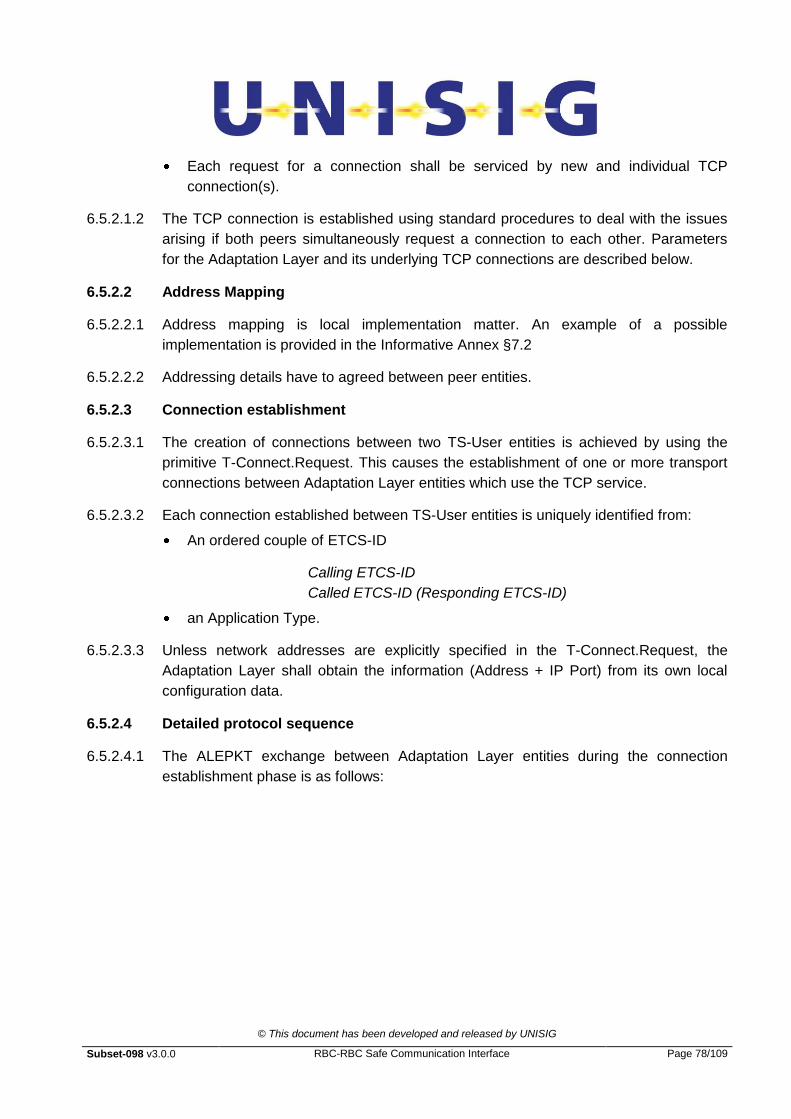
© This document has been developed and released by UNISIG
Subset-098 v3.0.0 RBC-RBC Safe Communication Interface Page 78/109
Each request for a connection shall be serviced by new and individual TCP
connection(s).
6.5.2.1.2 The TCP connection is established using standard procedures to deal with the issues
arising if both peers simultaneously request a connection to each other. Parameters
for the Adaptation Layer and its underlying TCP connections are described below.
6.5.2.2 Address Mapping
6.5.2.2.1 Address mapping is local implementation matter. An example of a possible
implementation is provided in the Informative Annex §7.2
6.5.2.2.2 Addressing details have to agreed between peer entities.
6.5.2.3 Connection establishment
6.5.2.3.1 The creation of connections between two TS-User entities is achieved by using the
primitive T-Connect.Request. This causes the establishment of one or more transport
connections between Adaptation Layer entities which use the TCP service.
6.5.2.3.2 Each connection established between TS-User entities is uniquely identified from:
An ordered couple of ETCS-ID
Calling ETCS-ID
Called ETCS-ID (Responding ETCS-ID)
an Application Type.
6.5.2.3.3 Unless network addresses are explicitly specified in the T-Connect.Request, the
Adaptation Layer shall obtain the information (Address + IP Port) from its own local
configuration data.
6.5.2.4 Detailed protocol sequence
6.5.2.4.1 The ALEPKT exchange between Adaptation Layer entities during the connection
establishment phase is as follows:
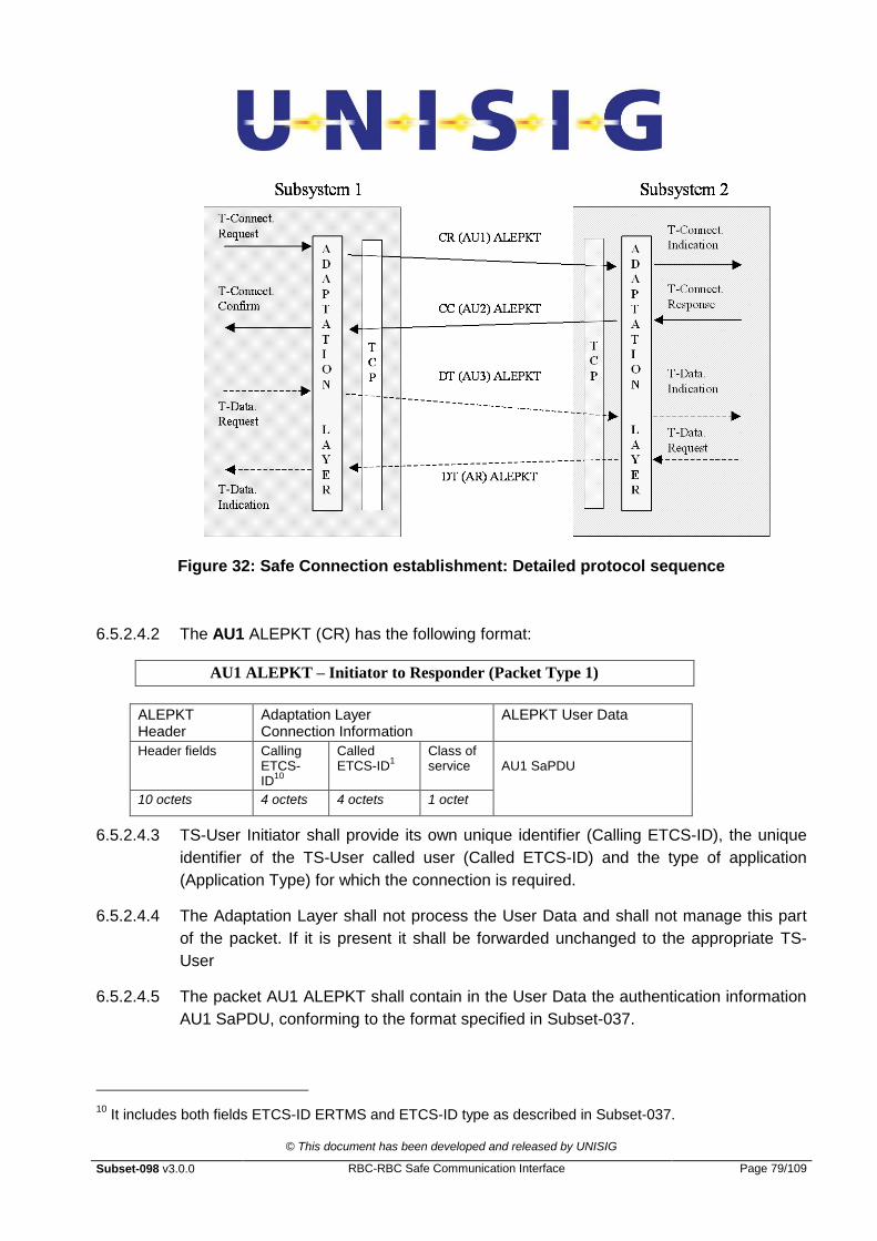
© This document has been developed and released by UNISIG
Subset-098 v3.0.0 RBC-RBC Safe Communication Interface Page 79/109
Figure 32: Safe Connection establishment: Detailed protocol sequence
6.5.2.4.2 The AU1 ALEPKT (CR) has the following format:
AU1 ALEPKT – Initiator to Responder (Packet Type 1)
ALEPKT Header
Adaptation Layer Connection Information
ALEPKT User Data
Header fields Calling ETCS-ID
10
Called ETCS-ID
1 Class of service
AU1 SaPDU
10 octets 4 octets 4 octets 1 octet
6.5.2.4.3 TS-User Initiator shall provide its own unique identifier (Calling ETCS-ID), the unique
identifier of the TS-User called user (Called ETCS-ID) and the type of application
(Application Type) for which the connection is required.
6.5.2.4.4 The Adaptation Layer shall not process the User Data and shall not manage this part
of the packet. If it is present it shall be forwarded unchanged to the appropriate TS-
User
6.5.2.4.5 The packet AU1 ALEPKT shall contain in the User Data the authentication information
AU1 SaPDU, conforming to the format specified in Subset-037.
10
It includes both fields ETCS-ID ERTMS and ETCS-ID type as described in Subset-037.
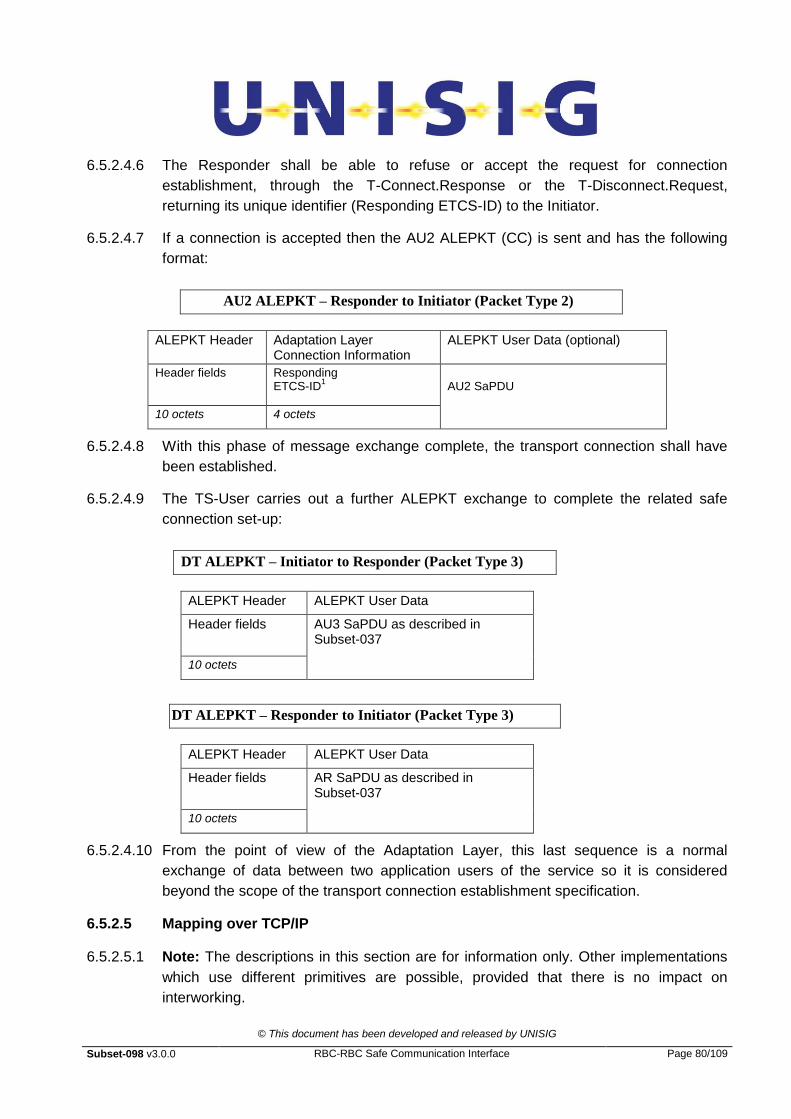
© This document has been developed and released by UNISIG
Subset-098 v3.0.0 RBC-RBC Safe Communication Interface Page 80/109
6.5.2.4.6 The Responder shall be able to refuse or accept the request for connection
establishment, through the T-Connect.Response or the T-Disconnect.Request,
returning its unique identifier (Responding ETCS-ID) to the Initiator.
6.5.2.4.7 If a connection is accepted then the AU2 ALEPKT (CC) is sent and has the following
format:
AU2 ALEPKT – Responder to Initiator (Packet Type 2)
ALEPKT Header Adaptation Layer Connection Information
ALEPKT User Data (optional)
Header fields Responding ETCS-ID
1 AU2 SaPDU
10 octets 4 octets
6.5.2.4.8 With this phase of message exchange complete, the transport connection shall have
been established.
6.5.2.4.9 The TS-User carries out a further ALEPKT exchange to complete the related safe
connection set-up:
DT ALEPKT – Initiator to Responder (Packet Type 3)
ALEPKT Header ALEPKT User Data
Header fields AU3 SaPDU as described in Subset-037
10 octets
DT ALEPKT – Responder to Initiator (Packet Type 3)
ALEPKT Header ALEPKT User Data
Header fields AR SaPDU as described in Subset-037
10 octets
6.5.2.4.10 From the point of view of the Adaptation Layer, this last sequence is a normal
exchange of data between two application users of the service so it is considered
beyond the scope of the transport connection establishment specification.
6.5.2.5 Mapping over TCP/IP
6.5.2.5.1 Note: The descriptions in this section are for information only. Other implementations
which use different primitives are possible, provided that there is no impact on
interworking.
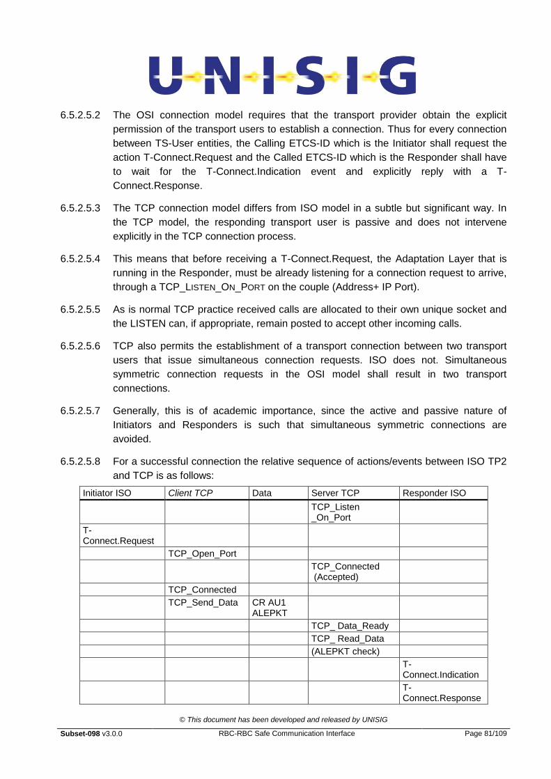
© This document has been developed and released by UNISIG
Subset-098 v3.0.0 RBC-RBC Safe Communication Interface Page 81/109
6.5.2.5.2 The OSI connection model requires that the transport provider obtain the explicit
permission of the transport users to establish a connection. Thus for every connection
between TS-User entities, the Calling ETCS-ID which is the Initiator shall request the
action T-Connect.Request and the Called ETCS-ID which is the Responder shall have
to wait for the T-Connect.Indication event and explicitly reply with a T-
Connect.Response.
6.5.2.5.3 The TCP connection model differs from ISO model in a subtle but significant way. In
the TCP model, the responding transport user is passive and does not intervene
explicitly in the TCP connection process.
6.5.2.5.4 This means that before receiving a T-Connect.Request, the Adaptation Layer that is
running in the Responder, must be already listening for a connection request to arrive,
through a TCP_LISTEN_ON_PORT on the couple (Address+ IP Port).
6.5.2.5.5 As is normal TCP practice received calls are allocated to their own unique socket and
the LISTEN can, if appropriate, remain posted to accept other incoming calls.
6.5.2.5.6 TCP also permits the establishment of a transport connection between two transport
users that issue simultaneous connection requests. ISO does not. Simultaneous
symmetric connection requests in the OSI model shall result in two transport
connections.
6.5.2.5.7 Generally, this is of academic importance, since the active and passive nature of
Initiators and Responders is such that simultaneous symmetric connections are
avoided.
6.5.2.5.8 For a successful connection the relative sequence of actions/events between ISO TP2
and TCP is as follows:
Initiator ISO Client TCP Data Server TCP Responder ISO
TCP_Listen _On_Port
T-Connect.Request
TCP_Open_Port
TCP_Connected (Accepted)
TCP_Connected
TCP_Send_Data CR AU1 ALEPKT
TCP_ Data_Ready
TCP_ Read_Data
(ALEPKT check)
T-Connect.Indication
T-Connect.Response
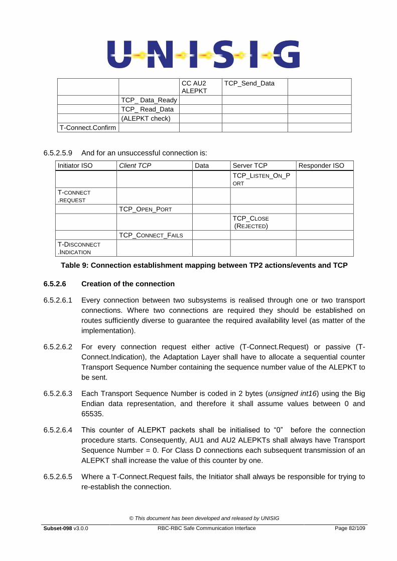
© This document has been developed and released by UNISIG
Subset-098 v3.0.0 RBC-RBC Safe Communication Interface Page 82/109
CC AU2 ALEPKT
TCP_Send_Data
TCP_ Data_Ready
TCP_ Read_Data
(ALEPKT check)
T-Connect.Confirm
6.5.2.5.9 And for an unsuccessful connection is:
Initiator ISO Client TCP Data Server TCP Responder ISO
TCP_LISTEN_ON_PORT
T-CONNECT .REQUEST
TCP_OPEN_PORT
TCP_CLOSE (REJECTED)
TCP_CONNECT_FAILS
T-DISCONNECT .INDICATION
Table 9: Connection establishment mapping between TP2 actions/events and TCP
6.5.2.6 Creation of the connection
6.5.2.6.1 Every connection between two subsystems is realised through one or two transport
connections. Where two connections are required they should be established on
routes sufficiently diverse to guarantee the required availability level (as matter of the
implementation).
6.5.2.6.2 For every connection request either active (T-Connect.Request) or passive (T-
Connect.Indication), the Adaptation Layer shall have to allocate a sequential counter
Transport Sequence Number containing the sequence number value of the ALEPKT to
be sent.
6.5.2.6.3 Each Transport Sequence Number is coded in 2 bytes (unsigned int16) using the Big
Endian data representation, and therefore it shall assume values between 0 and
65535.
6.5.2.6.4 This counter of ALEPKT packets shall be initialised to “0” before the connection
procedure starts. Consequently, AU1 and AU2 ALEPKTs shall always have Transport
Sequence Number = 0. For Class D connections each subsequent transmission of an
ALEPKT shall increase the value of this counter by one.
6.5.2.6.5 Where a T-Connect.Request fails, the Initiator shall always be responsible for trying to
re-establish the connection.
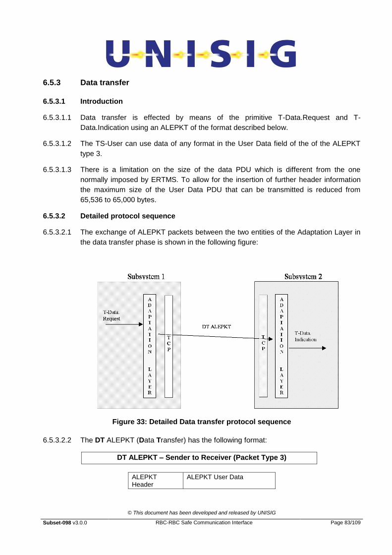
© This document has been developed and released by UNISIG
Subset-098 v3.0.0 RBC-RBC Safe Communication Interface Page 83/109
6.5.3 Data transfer
6.5.3.1 Introduction
6.5.3.1.1 Data transfer is effected by means of the primitive T-Data.Request and T-
Data.Indication using an ALEPKT of the format described below.
6.5.3.1.2 The TS-User can use data of any format in the User Data field of the of the ALEPKT
type 3.
6.5.3.1.3 There is a limitation on the size of the data PDU which is different from the one
normally imposed by ERTMS. To allow for the insertion of further header information
the maximum size of the User Data PDU that can be transmitted is reduced from
65,536 to 65,000 bytes.
6.5.3.2 Detailed protocol sequence
6.5.3.2.1 The exchange of ALEPKT packets between the two entities of the Adaptation Layer in
the data transfer phase is shown in the following figure:
Figure 33: Detailed Data transfer protocol sequence
6.5.3.2.2 The DT ALEPKT (Data Transfer) has the following format:
DT ALEPKT – Sender to Receiver (Packet Type 3)
ALEPKT Header
ALEPKT User Data
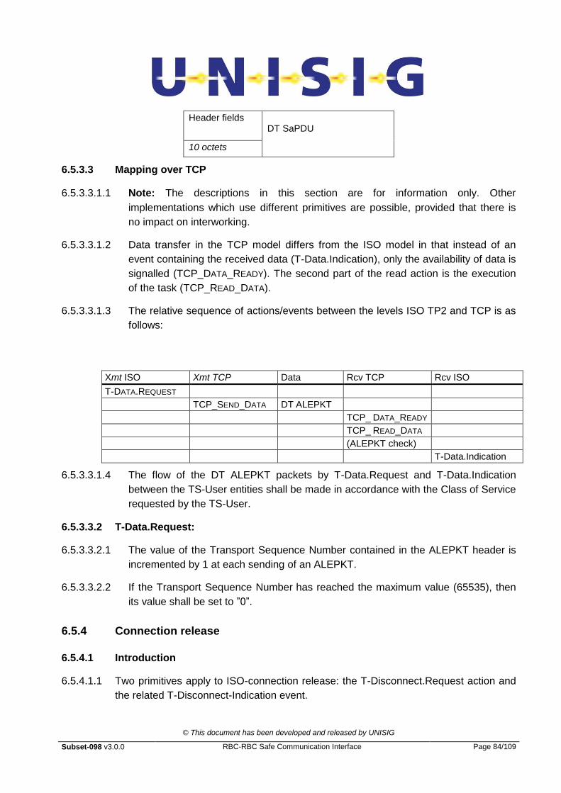
© This document has been developed and released by UNISIG
Subset-098 v3.0.0 RBC-RBC Safe Communication Interface Page 84/109
Header fields DT SaPDU
10 octets
6.5.3.3 Mapping over TCP
6.5.3.3.1.1 Note: The descriptions in this section are for information only. Other
implementations which use different primitives are possible, provided that there is
no impact on interworking.
6.5.3.3.1.2 Data transfer in the TCP model differs from the ISO model in that instead of an
event containing the received data (T-Data.Indication), only the availability of data is
signalled (TCP_DATA_READY). The second part of the read action is the execution
of the task (TCP_READ_DATA).
6.5.3.3.1.3 The relative sequence of actions/events between the levels ISO TP2 and TCP is as
follows:
Xmt ISO Xmt TCP Data Rcv TCP Rcv ISO
T-DATA.REQUEST
TCP_SEND_DATA DT ALEPKT
TCP_ DATA_READY
TCP_ READ_DATA
(ALEPKT check)
T-Data.Indication
6.5.3.3.1.4 The flow of the DT ALEPKT packets by T-Data.Request and T-Data.Indication
between the TS-User entities shall be made in accordance with the Class of Service
requested by the TS-User.
6.5.3.3.2 T-Data.Request:
6.5.3.3.2.1 The value of the Transport Sequence Number contained in the ALEPKT header is
incremented by 1 at each sending of an ALEPKT.
6.5.3.3.2.2 If the Transport Sequence Number has reached the maximum value (65535), then
its value shall be set to ”0”.
6.5.4 Connection release
6.5.4.1 Introduction
6.5.4.1.1 Two primitives apply to ISO-connection release: the T-Disconnect.Request action and
the related T-Disconnect-Indication event.
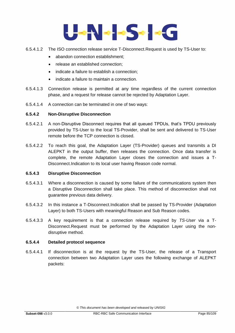
© This document has been developed and released by UNISIG
Subset-098 v3.0.0 RBC-RBC Safe Communication Interface Page 85/109
6.5.4.1.2 The ISO connection release service T-Disconnect.Request is used by TS-User to:
abandon connection establishment;
release an established connection;
indicate a failure to establish a connection;
indicate a failure to maintain a connection.
6.5.4.1.3 Connection release is permitted at any time regardless of the current connection
phase, and a request for release cannot be rejected by Adaptation Layer.
6.5.4.1.4 A connection can be terminated in one of two ways:
6.5.4.2 Non-Disruptive Disconnection
6.5.4.2.1 A non-Disruptive Disconnect requires that all queued TPDUs, that‟s TPDU previously
provided by TS-User to the local TS-Provider, shall be sent and delivered to TS-User
remote before the TCP connection is closed.
6.5.4.2.2 To reach this goal, the Adaptation Layer (TS-Provider) queues and transmits a DI
ALEPKT in the output buffer, then releases the connection. Once data transfer is
complete, the remote Adaptation Layer closes the connection and issues a T-
Disconnect.Indication to its local user having Reason code normal.
6.5.4.3 Disruptive Disconnection
6.5.4.3.1 Where a disconnection is caused by some failure of the communications system then
a Disruptive Disconnection shall take place. This method of disconnection shall not
guarantee previous data delivery.
6.5.4.3.2 In this instance a T-Disconnect.Indication shall be passed by TS-Provider (Adaptation
Layer) to both TS-Users with meaningful Reason and Sub Reason codes.
6.5.4.3.3 A key requirement is that a connection release required by TS-User via a T-
Disconnect.Request must be performed by the Adaptation Layer using the non-
disruptive method.
6.5.4.4 Detailed protocol sequence
6.5.4.4.1 If disconnection is at the request by the TS-User, the release of a Transport
connection between two Adaptation Layer uses the following exchange of ALEPKT
packets:
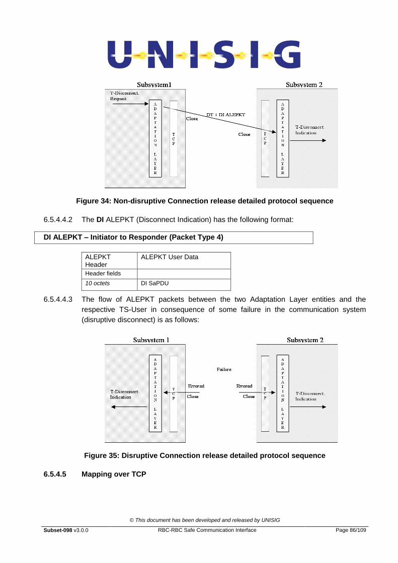
© This document has been developed and released by UNISIG
Subset-098 v3.0.0 RBC-RBC Safe Communication Interface Page 86/109
Figure 34: Non-disruptive Connection release detailed protocol sequence
6.5.4.4.2 The DI ALEPKT (Disconnect Indication) has the following format:
DI ALEPKT – Initiator to Responder (Packet Type 4)
ALEPKT Header
ALEPKT User Data
Header fields
10 octets DI SaPDU
6.5.4.4.3 The flow of ALEPKT packets between the two Adaptation Layer entities and the
respective TS-User in consequence of some failure in the communication system
(disruptive disconnect) is as follows:
Figure 35: Disruptive Connection release detailed protocol sequence
6.5.4.5 Mapping over TCP
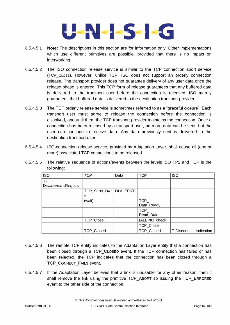
© This document has been developed and released by UNISIG
Subset-098 v3.0.0 RBC-RBC Safe Communication Interface Page 87/109
6.5.4.5.1 Note: The descriptions in this section are for information only. Other implementations
which use different primitives are possible, provided that there is no impact on
interworking.
6.5.4.5.2 The ISO connection release service is similar to the TCP connection abort service
(TCP_CLOSE). However, unlike TCP, ISO does not support an orderly connection
release. The transport provider does not guarantee delivery of any user data once the
release phase is entered. This TCP form of release guarantees that any buffered data
is delivered to the transport user before the connection is released. ISO merely
guarantees that buffered data is delivered to the destination transport provider.
6.5.4.5.3 The TCP orderly release service is sometimes referred to as a “graceful closure”. Each
transport user must agree to release the connection before the connection is
dissolved, and until then, the TCP transport provider maintains the connection. Once a
connection has been released by a transport user, no more data can be sent, but the
user can continue to receive data. Any data previously sent is delivered to the
destination transport user.
6.5.4.5.4 ISO-connection release service, provided by Adaptation Layer, shall cause all (one or
more) associated TCP connections to be released.
6.5.4.5.5 The relative sequence of actions/events between the levels ISO TP2 and TCP is the
following:
ISO TCP Data TCP ISO
T-DISCONNECT.REQUEST
TCP_SEND_DAT
A DI ALEPKT
(wait) TCP_ Data_Ready
TCP_ Read_Data
TCP_Close (ALEPKT check)
TCP_Close
TCP_Closed TCP_Closed T-Disconnect.Indication
6.5.4.5.6 The remote TCP entity indicates to the Adaptation Layer entity that a connection has
been closed through a TCP_CLOSED event. If the TCP connection has failed or has
been rejected, the TCP indicates that the connection has been closed through a
TCP_CONNECT_FAILS event.
6.5.4.5.7 If the Adaptation Layer believes that a link is unusable for any other reason, then it
shall remove the link using the primitive TCP_ABORT so issuing the TCP_ERRORED
event to the other side of the connection.

© This document has been developed and released by UNISIG
Subset-098 v3.0.0 RBC-RBC Safe Communication Interface Page 88/109
6.5.4.6 Normal disconnection at the request of the TS-User
6.5.4.6.1 When a TS-User wishes to terminate its relationship with a remote TS-User it does so
using a T-Disconnect.Request. On receipt of this primitive the local Adaptation Layer
shall close all TCP connections using the TCP_CLOSE action on each TCP connection
that is open at the time of the request.
6.5.4.6.2 Once all data has been transferred (including the request) the TCP connection shall be
closed in the other direction.
6.5.4.6.3 Note, in order to trigger the equivalent of a T-Disconnect.Indication event at the remote
entity, all TCP connections associated with the Safety Layer connection must be
closed. The remote TCP entity indicates to the local Adaptation Layer entity that a
connection has been closed through the TCP_CLOSED event. When a closing TCP link
is the last one remaining for a specific ISO connection the Adaptation Layer shall issue
the T-Disconnect.Indication with appropriate error codes towards the TS-User.
6.5.4.7 Anomalous release by Adaptation Layer
6.5.4.7.1 In case of an anomalous disconnection by the local Adaptation Layer entity, all the
TCP associated links shall be released using the TCP_CLOSE action. The user of the
remote service shall be informed immediately as soon as the last TCP_CLOSED and
shall produce the T-Disconnect.Indication event to the TS-user (as in the normal
disconnection but with appropriate Reason and Sub-Reason parameters).
6.5.4.8 Anomalous release by TCP
6.5.4.8.1 The case of an anomalous release of a TCP link is more complex.
6.5.4.8.2 If the TCP link released for is the last, it shall cause the dispatch of the T-
Disconnect.Indication event with appropriate error to the TS-User.
6.5.4.8.3 If any TCP channel being one of two links is released for some reason and the other
link is still active, then the initiating Adaptation Layer shall try to restore the connection
with the remote Adaptation Layer without informing the TS-User.
6.5.4.8.4 In the case of re-connect failure the Adaptation Layer shall have to try again for a
maximum number of times after which it shall have to report the problem through T-
Report.Indication with an appropriate error code to the TS-User or a management
entity.

© This document has been developed and released by UNISIG
Subset-098 v3.0.0 RBC-RBC Safe Communication Interface Page 89/109
6.6 Operation and Redundancy Management for different Classes
of Service
6.6.1 Class A (optional for implementation)
6.6.1.1 Definitions
6.6.1.1.1 If two links are used between ALE entities, one is configured as the normal one, and
the other as the redundant one. This configuration is fixed.
6.6.1.1.2 If two links are used between two ALE entities, the link used to establish/release the
ALE connection or to exchange ALE packets containing application data is called the
“active link”. The other link is called the “non-active link”. In case of switching between
the two links, the active link becomes the non-active link and conversely.
6.6.1.1.3 Normal/Redundant and Active/Non-Active are two different concepts. In this way,
either the normal or redundant link can be active or non-active. Normal/Redundant is
physically fixed, while active/non-active is dynamically assigned.
6.6.1.1.4 Class A is coded as 0x00.
6.6.1.2 ALE Connection establishment
6.6.1.2.1 If the normal link is available, this one shall initially be used to establish the ALE
connection and transfer all user data ALEPKTs between the peers. This path shall
have the N/R flag of the ALEPKT header set to value 1.
6.6.1.2.2 As soon as practicable, a second TCP connection shall also be started between two
alternative IP addresses for the peers on a different physical link. This connection shall
be used as the redundant link if required. The N/R flag for any messages sent on this
connection shall have the N/R flag set to 0.
6.6.1.2.3 In case of non availability of the normal link, the redundant link shall be used to
establish the ALE connection and to transfer all user data ALEPKTs between the
peers. The N/R flag for any messages sent on this connection shall have the N/R flag
set to 0.
6.6.1.2.4 The initiator chooses the link that will be used to exchange packet type 1 and 2 - this
will be the active link for the initiator. The packet type 1 and 2 shall not be exchanged
on the non-active link. When the responder receives the packet type 1 from one link,
this becomes the active one for the responder. The packet type 2 shall be sent on this
active link. The initiator shall check that packet type 2 is received on the active link. In
case of failure of the check, the ALE connection shall be released.
6.6.1.2.5 The use of packet types 3, 251, 253, 254 and 255 is not allowed before ALE
connection establishment (exchange of packet types 1 and 2).
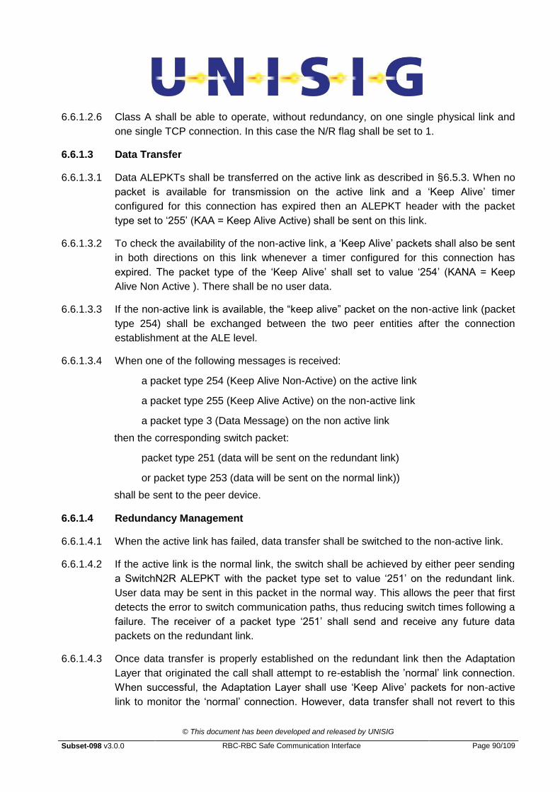
© This document has been developed and released by UNISIG
Subset-098 v3.0.0 RBC-RBC Safe Communication Interface Page 90/109
6.6.1.2.6 Class A shall be able to operate, without redundancy, on one single physical link and
one single TCP connection. In this case the N/R flag shall be set to 1.
6.6.1.3 Data Transfer
6.6.1.3.1 Data ALEPKTs shall be transferred on the active link as described in §6.5.3. When no
packet is available for transmission on the active link and a „Keep Alive‟ timer
configured for this connection has expired then an ALEPKT header with the packet
type set to „255‟ (KAA = Keep Alive Active) shall be sent on this link.
6.6.1.3.2 To check the availability of the non-active link, a „Keep Alive‟ packets shall also be sent
in both directions on this link whenever a timer configured for this connection has
expired. The packet type of the „Keep Alive‟ shall set to value „254‟ (KANA = Keep
Alive Non Active ). There shall be no user data.
6.6.1.3.3 If the non-active link is available, the “keep alive” packet on the non-active link (packet
type 254) shall be exchanged between the two peer entities after the connection
establishment at the ALE level.
6.6.1.3.4 When one of the following messages is received:
a packet type 254 (Keep Alive Non-Active) on the active link
a packet type 255 (Keep Alive Active) on the non-active link
a packet type 3 (Data Message) on the non active link
then the corresponding switch packet:
packet type 251 (data will be sent on the redundant link)
or packet type 253 (data will be sent on the normal link))
shall be sent to the peer device.
6.6.1.4 Redundancy Management
6.6.1.4.1 When the active link has failed, data transfer shall be switched to the non-active link.
6.6.1.4.2 If the active link is the normal link, the switch shall be achieved by either peer sending
a SwitchN2R ALEPKT with the packet type set to value „251‟ on the redundant link.
User data may be sent in this packet in the normal way. This allows the peer that first
detects the error to switch communication paths, thus reducing switch times following a
failure. The receiver of a packet type „251‟ shall send and receive any future data
packets on the redundant link.
6.6.1.4.3 Once data transfer is properly established on the redundant link then the Adaptation
Layer that originated the call shall attempt to re-establish the ‟normal‟ link connection.
When successful, the Adaptation Layer shall use „Keep Alive‟ packets for non-active
link to monitor the „normal‟ connection. However, data transfer shall not revert to this
© This document has been developed and released by UNISIG
Subset-098 v3.0.0 RBC-RBC Safe Communication Interface Page 91/109
link unless a problem is detected on the redundant link. When needed this shall be
achieved by either Adaptation Layer sending, on the normal link, a SwitchR2N
ALEPKT with the type set to the value „253‟. User data may be sent in this packet in
the normal way.
6.6.1.4.4 If the active link is the redundant link and it fails, the switch shall be achieved by either
peer sending a SwitchR2N ALEPKT with the packet type set to value „253‟ on the
normal link. User data may be sent in this packet in the normal way. The receiver of a
packet type „253‟ shall send and receive any future data packets on the normal link.
6.6.1.4.5 Once data transfer is properly established on the normal link, the Adaptation Layer that
originated the call shall attempt to re-establish the redundant link connection. When
successful, the Adaptation Layer shall use „Keep Alive‟ packets for non-active link to
monitor the redundant link connection. However, data transfer shall not revert to this
link unless a problem is detected on the normal link. When needed this shall be
achieved by either Adaptation Layer sending, on the redundant link, a SwitchN2R
ALEPKT with the type set to the value „251‟.
6.6.1.4.6 Note that the message type of the „Keep Alive‟ depends on whether a link is being
used to transfer data or not. It does not depend on whether the link is the nominated
normal or redundant path. The link transferring data always uses „Keep Alive‟ packet
type „255‟, the link that is available as a standby always uses „Keep Alive‟ packet „254‟.
This technique enables the system to quickly recover if „switch‟ messages are lost or
delayed. (If a „254‟ packet is received on the new active link after a switch message
has been sent then another switch message should be transmitted until either data or
„255‟ messages are received on the active link).
6.6.1.5 Normal release
6.6.1.5.1 When a Safety Layer entity wishes to terminate its relationship with a remote entity it
does so using a T-Disconnect.Request. The DI ALEPKT is exchanged on the active
link. On receipt of this primitive the local Adaptation Layer shall close all TCP
connections using the TCP-CLOSE primitive on each TCP connection that is open at
the time of the request. Once all data has been transferred (including the request) the
TCP connection shall be closed in the other direction.
6.6.1.5.2 A packet type 4 (DI) can be sent only in the following cases:
by the initiator after the packet type 1 was sent;
by the responder after the packet type 1 type was received.
Note, in order to trigger the equivalent of a T-Disconnect.Indication at the remote
entity, all TCP connections associated with the Safety Layer connection shall be
closed. The remote TCP entity indicates to the Adaptation Layer entity that a
connection has been closed through TCP-CLOSING event. When a TCP connection is
© This document has been developed and released by UNISIG
Subset-098 v3.0.0 RBC-RBC Safe Communication Interface Page 92/109
the last remaining for this Safety Layer relationship then this triggers the Adaptation
Layer to send a T-Disconnect.Indication with appropriate reason codes to its local
Safety Layer.
6.6.1.6 Abnormal release
6.6.1.6.1 In the case of an abnormal release by the local Safety Layer entity, all associated TCP
connections are released using TCP-CLOSE. The remote service user is to be
immediately informed when the last TCP-CLOSING event triggers the T-
Disconnect.Indication primitive (as in normal release but with different codes described
in §6.7).
6.6.1.6.2 The case of abnormal release of a TCP connection is more complex.
6.6.1.6.3 If a TCP connection is the last remaining this triggers a T-Disconnect.Indication with
appropriate reason codes.
6.6.1.6.4 If the released connection is the non-active link (the active link being still available)
then the Adaptation Layer shall attempt to re-connect to the remote entity without
informing the Adaptation Layer user.
6.6.1.6.5 If the connection closed is the active link and the non-active link is still operating then
the Adaptation Layer shall first switch all data transfer to the non-active link before
attempting to re-establish the normal connection. .
6.6.1.6.6 If the link that notifies the Adaptation Layer of connection loss is the last remaining
circuit then this triggers a T-Disconnect.Indication with appropriate reason codes. It
must be stressed that in order to trigger a T-Disconnect.Indication, all TCP
connections associated with the Safety Layer connection must be closed. The remote
TCP entity indicates to the Adaptation Layer entity that a connection has been closed
through TCP-CLOSING event. If the TCP connection has failed the TCP indicates that
the connection has been closed through TCP-ERROR event.
6.6.1.6.7 If the Adaptation Layer believes that a connection is unusable for some reason then it
may remove the connection using the ABORT primitive. Unless this is the last TCP
connection open it shall not inform the Safety Layer.
6.6.2 Class D
6.6.2.1 Connection
6.6.2.1.1 For Class D, all ALEPKTs are sent on all connections. Transport connections shall
support one single safe connection between two entities. One TCP connection shall be
created at the same time on each physical link.

© This document has been developed and released by UNISIG
Subset-098 v3.0.0 RBC-RBC Safe Communication Interface Page 93/109
6.6.2.1.2 One, two or more physical links may be used. This section is written assuming two
physical links. The following requirements should be modified to reflect the number of
physical links available.
6.6.2.1.3 For example, on one single physical link (no redundancy) and therefore one single
TCP connection, the N/R flag shall be set to „1‟.
6.6.2.1.4 Connection Establishment packets AU1 ALEPKT (CR) and AU2 ALEPKT (CC)
complete with User Data, shall be sent in an identical way on both the TCP transport
connections using the Transport Sequence Number value of “0”.
6.6.2.1.5 During the connection establishment phase, the ALE entity shall use the first AU1 and
AU2 ALEPKT received, and discard any copies received.
6.6.2.1.6 Class D is coded as 0x03.
6.6.2.2 Data Transfer
6.6.2.2.1 All Data ALEPKTs shall be transferred on both TCP connections. The same Transport
Sequence Number shall be transmitted on both TCP connections.
6.6.2.2.2 The receiver shall observe the ALEPKTs received on both TCP connections.
6.6.2.2.3 The receiver shall discard any ALEPKT with a Transport Sequence Number which has
the same value as (or less than) an ALEPKT that has already been passed to the TS
user.
6.6.2.2.4 At least two different behaviours are possible at the receiver side:
a) An ALE packet containing a Transport Sequence Number greater than the
last one delivered to the ALE user shall be passed to the ALE user.
b) An ALE packet containing a Transport Sequence Number equal to the
„previous Transport Sequence Number delivered to the ALE user + 1‟ shall
be passed to the ALE user. Packets containing a Transport Sequence
Number greater than the last one +1 shall be discarded.
6.6.2.2.5 The choice between a) and b) is a configuration matter.
6.6.2.2.6 Behaviour b) has to be selected if no missing ALEPKT is allowed.
6.6.2.2.7 In the case of any failure of the data transfer on one TCP channel, the Adaptation
Layer shall not make any attempt to resolve the problem, but shall simply release the
connection and reject the data; this failure can be reported to the ALE user, as an
implementation matter.
6.6.2.3 Redundancy Management

© This document has been developed and released by UNISIG
Subset-098 v3.0.0 RBC-RBC Safe Communication Interface Page 94/109
6.6.2.3.1 When a transmitter is unable to send data on a TCP connection or a TCP connection
is deemed in error the TCP connection shall be closed. The sending of Data ALEPKTs
through the other link shall continue. The Adaptation Layer entity that initiated the
original connection (the initiator) shall attempt to re-establish any failed TCP
connection.
6.6.2.3.2 At the receiver, any TCP connection deemed to have failed shall be closed. The
receiver shall take no further action unless it was the initiator of the TCP call. In this
case it shall attempt to re-establish the connection.
6.6.2.3.3 All ALEPKTs shall be taken from the remaining TCP connection.
6.6.2.4 Connection Monitoring
6.6.2.4.1 Connection and physical link monitoring in Class D shall be performed using the
standard Keep Alive feature provided by TCP.
6.6.2.4.2 Both TCP entities shall enable the Keep Alive feature.
6.6.2.4.3 NOTE: In case the Application is sending data in a cyclic way, connection monitoring at
TCP level is not required.
6.6.3 Summary of ALEPKT
6.6.3.1.1 This section summarises the various ALEPKTs used by ALE.
ALEPKT
Type
ALEPKT
name
scope User Data link Class
using
1 AU1 (CR) Request a
connection to peer
AU1 Class D: N
and R
Class A:
active link
A & D
2 AU2 (CC) Accept a
connection from
peer
AU2 Class D: N
and R
Class A:
active link
A & D
3 DT Transfer user data SaPDU Class D: N
and R
Class A:
active link
A & D
4 DI Release a
connection
DI SaPDU Class D: N
and R
A & D
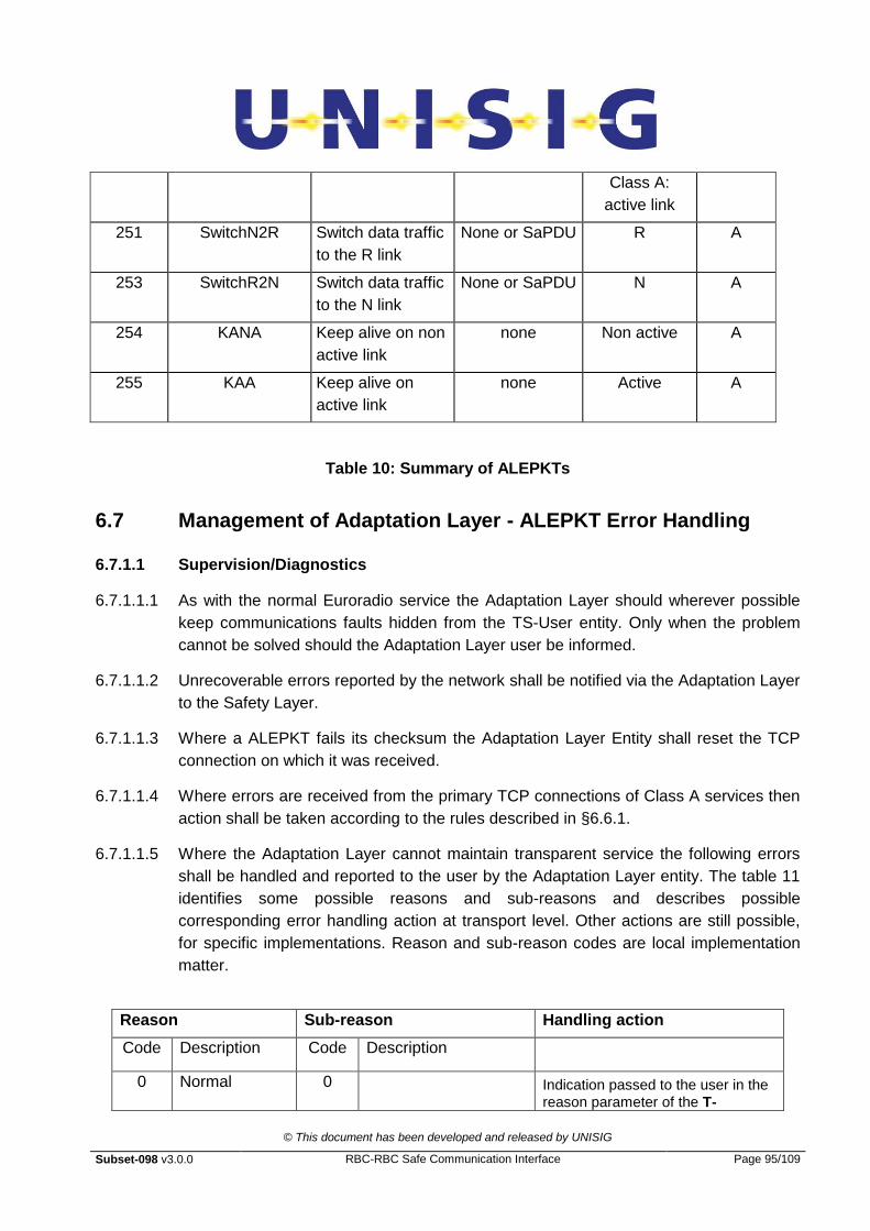
© This document has been developed and released by UNISIG
Subset-098 v3.0.0 RBC-RBC Safe Communication Interface Page 95/109
Class A:
active link
251 SwitchN2R Switch data traffic
to the R link
None or SaPDU R A
253 SwitchR2N Switch data traffic
to the N link
None or SaPDU N A
254 KANA Keep alive on non
active link
none Non active A
255 KAA Keep alive on
active link
none Active
A
Table 10: Summary of ALEPKTs
6.7 Management of Adaptation Layer - ALEPKT Error Handling
6.7.1.1 Supervision/Diagnostics
6.7.1.1.1 As with the normal Euroradio service the Adaptation Layer should wherever possible
keep communications faults hidden from the TS-User entity. Only when the problem
cannot be solved should the Adaptation Layer user be informed.
6.7.1.1.2 Unrecoverable errors reported by the network shall be notified via the Adaptation Layer
to the Safety Layer.
6.7.1.1.3 Where a ALEPKT fails its checksum the Adaptation Layer Entity shall reset the TCP
connection on which it was received.
6.7.1.1.4 Where errors are received from the primary TCP connections of Class A services then
action shall be taken according to the rules described in §6.6.1.
6.7.1.1.5 Where the Adaptation Layer cannot maintain transparent service the following errors
shall be handled and reported to the user by the Adaptation Layer entity. The table 11
identifies some possible reasons and sub-reasons and describes possible
corresponding error handling action at transport level. Other actions are still possible,
for specific implementations. Reason and sub-reason codes are local implementation
matter.
Reason Sub-reason Handling action
Code Description Code Description
0 Normal 0 Indication passed to the user in the
reason parameter of the T-

© This document has been developed and released by UNISIG
Subset-098 v3.0.0 RBC-RBC Safe Communication Interface Page 96/109
release Disconnect.Indication.
1 Network error 1 Number not assigned; invalid number format
Error indication is created by the local Adaptation Layer and passed to the user in the reason parameter
of the T-Disconnect.Indication. 2 Channel QoS is
unacceptable
3 Impossible to establish physical connection for other reasons
4 Address information incompatible with QoS requested.
2 Network resource not available
1 No channel available Indication of a transient error is created by the Adaptation Layer and is contained in the reason parameter of the
T-Disconnect.Indication
2 Network congestion
3 Other sub-reason
3 Service or option is temporarily not available
1 QoS not available Indication of a transient error is created by the Adaptation Layer and is contained in the reason parameter of the
T-Disconnect.Indication
2 Bearer capability not
available
5 Reason unknown
0 Error indication is created by the called Adaptation Layer and is contained in the reason parameter
of the T-Disconnect.Indication.
6 Unsupported Application
1 Requested Application type is not supported at the called address
Error indication is created by the called Adaptation Layer and is contained in the user data of the
DR-ALEPKT (type 4).
The calling Adaptation Layer shall report the error to the calling application using the
T-Disconnect.Indication with the corresponding reason and sub-reason codes.
2 Called user not known (e.g. No reply)
3 Called user not available (e.g. Busy)
7 Internal error 1 Mandatory element (e.g. primitive parameter) is missing
Error logged.
Invalid message discarded.
Indication passed to the user in the
reason parameter of the T-
Disconnect.Indication.
2 Inappropriate state
3 Other sub-reasons
Note: All other reason/sub-reasons are reserved
Table 11: Error reports
© This document has been developed and released by UNISIG
Subset-098 v3.0.0 RBC-RBC Safe Communication Interface Page 97/109
6.8 Lower layers of protocol stack
6.8.1 Introduction
6.8.1.1.1 It is not the intention of this specification to restrict the way in which an underlying
network solution is to be implemented. As such only minimum criteria for interworking
are to be applied.
6.8.2 TCP Parameter Negotiation (Mandatory)
6.8.2.1.1 The parameters that must be taken into account in TCP connection establishment by
the Adaptation Layer are restricted to those described below:
6.8.2.2 Max MTU size
6.8.2.2.1 The default values are 576 bytes for routed WAN links and 1500 for Ethernet LANs.
This parameter is directly mapped to the TCP parameter and determines the maximum
size of a Message Transfer Unit. Messages exceeding this size shall be sent in
multiple IP datagrams. This value is varied to optimise performance over different
physical media.
6.8.2.2.2 Using the IP default datagram size of 576 octets means that an ALEPKT should be
less than 512 bytes if it is desired to transmit it in a single IP datagram (by allowing 64
bytes for headers and trailers - see also notes on D bit and fragmentation). The choice
of 1460 bytes for Ethernet LANs is to allow for IEEE 802.3 frame sizes between 64 and
1518 bytes (assuming headers and trailers totalling up to 58 bytes).
6.8.2.2.3 This parameter in no way restricts the maximum message size that can be transmitted.
This is 65,536 bytes less the header sizes detailed above. In this specification a
maximum message size of 65,000 bytes is recommended (slightly under the maximum
SaPDU size allowed which is 64kB). Note that it is also possible to set a Max Segment
Size (MSS) between TCP entities that defines the maximum TCP segment size that
shall be transmitted.
6.8.2.3 Keep Alive acknowledgement timer (for Class D only)
6.8.2.3.1 This parameter is identical to the TCP parameter and allows user applications to be
notified when their network service times out. The time shall vary according to the
application requirements.
6.8.3 Network Service Definition
6.8.3.1.1 A standard TCP service shall be used over a standard IP network layer complying with
all associated RFCs.
© This document has been developed and released by UNISIG
Subset-098 v3.0.0 RBC-RBC Safe Communication Interface Page 98/109
6.8.3.1.2 This specification should not restrict usage of newer IP versions like IPv6, see
[RFC2460].
6.8.4 Network Protocol
6.8.4.1.1 The implementation shall be conformant to the IP standard [RFC0791] that describes
IPv4.
6.8.4.1.2 It should be seen that messages that do not exceed the lengths of MTU described in
§6.8.2.2 shall not be fragmented by the IP layer and shall be transmitted in a single
MTU.
6.8.4.1.3 To maximise performance implementers should take care to ensure that the MTU size
is set to the smallest size relevant to the media in the path and not necessarily to the
size that is determined by the RBC connection itself.
6.9 Adaptation Layer Configuration and Management
6.9.1 General
6.9.1.1.1 The configuration defines the parameters needed for the execution of the Adaptation
Layer protocol and the management of the Adaptation Layer itself.
6.9.2 Timer Parameter
6.9.2.1.1 The parameter „maximum connection establishment delay‟ is used for detecting
unacceptable delay during the connection establishment. This parameter value shall
vary according to the application but by default is 40 seconds (the same as the Safety
protocol see §5.3.1.1.5).
6.9.3 Call and ID-Management (Adaptation Layer and TCP)
6.9.3.1.1 Addressing conventions and mapping rules are matter of bilateral agreement for a
specific project.
© This document has been developed and released by UNISIG
Subset-098 v3.0.0 RBC-RBC Safe Communication Interface Page 99/109
7. INFORMATIVE ANNEX
7.1 TCP Parameter Negotiation
7.1.1 TCP Service options
7.1.1.1.1 Other optional features of TCP/IP may be used to provide a particular level of service.
It should be noted however that how QoS is achieved is a matter of implementation
and is not prescriptive. This said, meeting QoS requirements could result in a number
of possible actions including
The creation of multiple connections between end systems
The use of options within TCP such as push and urgent flags (possibly for high
priority data)
The setting of IP „Type of Service‟ options such as
Precedence : 3 bits signifying one of 8 levels of precedence
Low delay : D flag - at each hop select route with least known delay
High throughput : T bit - routers should select path with highest throughput
High reliability : R bit - network uses connection oriented links if available
Least „cost‟ : C bit - (if available) select route with lowest cost
7.1.1.1.2 It must be noted that „Type of Service‟ parameters are only useful if the intermediate
systems such as routers can act on them.
7.1.1.1.3 The following parameters passed from TCP to IP may also be useful
DF bit (don‟t fragment) - choose a network route that can handle the whole
datagram rather than fragmenting it. Note, if set, the receiving host shall either
receive the data in a single datagram or not at all.
MF bit (more fragments) - use this facility where messages are fragmented to
indicate that more fragments are still to come.
7.2 Address Mapping
7.2.1.1.1 This section provide an example of a possible implementation of the address mapping.
7.2.1.1.2 On receipt of the connect request from the TS-User entity (with address information as
described in §6.4.4 the Adaptation Layer performs the following actions.
© This document has been developed and released by UNISIG
Subset-098 v3.0.0 RBC-RBC Safe Communication Interface Page 100/109
7.2.1.1.3 If the T-Connect.Request contains full addressing information (meaning that the
Network Address field of the Safety Layer User Connect Request contains a value
that is not null or “0”) the Adaptation Layer attempts to establish transport
connection(s) using this information. (Note that for this to be successful a correct TCP
address must be defined.
7.2.1.1.4 If only ETCS-ids are contained in the T-Connect.Request (the Network Address is
null) then the Adaptation Layer performs the necessary look-up (via tables or some
other database) to obtain the full TCP addresses required to establish the connection.
7.2.1.1.5 If the Application Type in the T-Connect.Request so determines then the local
Adaptation Layer seeks to establish two connections to the remote Adaptation Layer.
7.2.1.1.6 If there is no network address or no ETCS-ID contained in the T-Connect.Request
primitive or there is a mapping error, the call has to be established towards the most
appropriate system by means of an agreed convention (or rejected with an appropriate
message sent to a supervisory management system).
7.2.1.1.7 The network address (port and IP address) by itself is not sufficient to identify a
particular remote Transport Service user entity. It is also necessary to refer to the
requested Transport Service user entity type by using a special identifier or address
qualifier, the application type contained in every ALEPKT.
7.2.1.1.8 Adaptation Layer entities and the Service user entities are bound together at TSAPs.
Every Adaptation Layer Service user entity may be bound to one or more TSAPs. This
is a matter of implementation. There is no relationship between TSAPs and
multiplexing. Each connection regardless of its TSAP id must be mapped to an
individual TCP port for the purpose of establishing a real connection. In the case of
Class A or D relationships a second TCP connection is also established and used as
described in §6.6.
7.2.1.1.9 If a Transport Service user entity (e.g. the safety layer entity) wants to establish a
connection with another Transport Service user entity, it provides information to
address the called Transport Service user (usually an ETCS-ID and the application
type, possibly the network address). This address information has to be mapped into
the format and structure requested by the TCP Service for connection establishment.
This is done by the Adaptation Layer, which is accessed by the Safety Layer Entity at
one or more TSAPs.

© This document has been developed and released by UNISIG
Subset-098 v3.0.0 RBC-RBC Safe Communication Interface Page 101/109
Port + IP
ERMS application (calling Safety Service user A)
SAI +
ER SL
Adaptation Layer
Adaptation layer entity
Calling TSAP
Address mapping
TCP
ERTMS application (called Safety Service user B)
SAI +
ER SL
Adaptation Layer
Called TSAP
TCP
TSAP TSAP
SaSAP SaSAP
Safety layer Safety layer
External address info
CdA = ETCS-ID, appl.type=xxx
IP Network
Applic. type =xxx Applic. type = ... CdA = ETCS-ID,
appl.type=xxx
Port + IP
Adaptation layer entity
Figure 36: Example of address mapping
7.2.1.1.10 The diagram above gives an example of address information mappings during the
connection establishment between Transport Services. The calling TS user entity (i.e.
in this example the safety layer entity) obtains the called address from the application
(ETCS-ID). The address information is be passed through the Safety Layer towards
the Adaptation Layer Transport Service. The Adaptation layer entity has the following
tasks:
to listen for incoming connections. A TCP LISTEN is posted on each and every
port willing to accept incoming connections. As is normal TCP practice received
calls are allocated to their own socket and the LISTEN remains posted;
to derive the called network address (TCP/IP address) from address information
indicating the called Transport Service User (unless it is already provided by the
SLE);
to generate the appropriate ALEPKTs as defined later in this section.
© This document has been developed and released by UNISIG
Subset-098 v3.0.0 RBC-RBC Safe Communication Interface Page 102/109
7.3 Data Link Layer
7.3.1 Ethernet
7.3.1.1 Logical Link Control
7.3.1.1.1 The data link layer for the connection of the system to a network should be appropriate
to its type.
7.3.1.1.2 For Ethernet it shall use LLC1 unacknowledged connectionless service to provide
support for the IP network layer. This is the standard protocol used to interconnect IP
devices over CSMA/CD LANs.
7.3.2 Media Access Control
7.3.2.1.1 This should be according to standard and appropriate to the media.
7.3.3 Wide Area connections
7.3.3.1.1 Wide Area connections may use X.25, HDLC, Frame Relay or PPP or other datalink
protocols, depending also on the media used.
7.4 Guideline for Key Management
7.4.1 Scope
7.4.1.1.1 Key management (KM) functions are required to establish interoperable services.
7.4.1.1.2 In the ERTMS system, when an RBC wishes to communicate with another RBC, it
shall be able to verify that communication is established with an authorised RBC and
vice versa. Consequently the authenticity and integrity of any information exchanged
between RBCs is also verified.
7.4.1.1.3 This guideline covers management of cryptographic keys as defined in UNISIG
EuroRadio FIS [Subset-037]. It describes general concepts, principles, and functions to
manage cryptographic materials used by the EuroRadio safety layer.
7.4.1.1.4 The procedures and aspects of key management inside a KM domain for trackside
entities are a matter of operational implementation by the railways.
7.4.2 KM Concepts and Principles
7.4.2.1 Introduction and background

© This document has been developed and released by UNISIG
Subset-098 v3.0.0 RBC-RBC Safe Communication Interface Page 103/109
7.4.2.1.1 The method of ensuring that both communicating entities are the ones they assert to
be, is based on an Identification and Authentication (I&A) dialogue. In order to ensure
complete protection, this procedure shall take place each time the peer entities
effectively start a new communication session between them.
7.4.2.1.2 After each successful I&A dialogue, data are protected using a Message
Authentication Code (MAC). The calculation of this code is based on the existence of
shared secret information only known by the entities that are actually communicating
with each other.
7.4.2.1.3 Both I&A dialogue and MAC calculation procedures are fully specified in the Safety
Functional Module described in UNISIG EuroRadio FIS [Subset-037]. These
procedures are based on cryptographic techniques that use secret keys. However,
Subset-037 does not specify any means to generate, distribute or update these keys.
7.4.2.1.4 Moreover, their full efficiency relies on the key secrecy that can only be guaranteed
when clear key management functions and system security policy are defined
according to implementation constraints and railway operational scenarios.
7.4.3 Phases and parties involved In KMS
7.4.3.1.1 Two different phases should be considered to define the parties involved in KMS:
1. During system development and commissioning (i.e. before authorisation to
service).
2. During system operation.
7.4.3.1.2 During phase 1 the following parties are involved:
• Suppliers of ETCS equipment
• Contracting entities
7.4.3.1.3 During phase 2 at the present state of the organisation of railways and probably valid
also for the near future, the following parties are involved:
• Key Management Centres (KMC)
• Infrastructure Managers (i.e. Operators of trackside ETCS equipment)
An Infrastructure Manager can perform the functions of KMC, for instance, but it is
also possible that other companies (even not belonging to the “railway world”) offer this
service.
7.4.3.1.4 The concept of parties is used in this guideline only to identify a role and a set of
“homogeneous” responsibilities. No assumption is made on any other aspect. In other
words, two or more different parties identified above may be the same organisation,
may be different departments of the same organisation, may be separate
undertakings, etc. Similarly, the organisations involved in any part of the KMS

© This document has been developed and released by UNISIG
Subset-098 v3.0.0 RBC-RBC Safe Communication Interface Page 104/109
functions may regulate their relationships and reciprocal responsibilities by means of
agreements, contracts, etc., that are out of the scope of this guideline.
7.4.4 General Principles
7.4.4.1.1 The following figure summarises the KMS context for RBC-RBC safe communication:
RBC
KMC - 1
KMC - 2
Inter domain :
Transfer of
KMAC keys
Domain internal:
Transfer of
KMAC keys
Domain internal:
Transfer of
KMAC keys
RBC
RBC
KM Domain - 1 KM Domain - 2
RBC-RBC
Interworking protected
by KSMAC key
Figure 37: KM context diagram
7.4.4.1.2 The KMAC transfer indicated in the figure is used to distribute, update and delete
KMACs.
7.4.4.1.3 A home KMC is responsible for generation, validation, distributing, updating and
revoking KMAC to all RBCs of its domain. Therefore each RBC shall use only their
home KMC for key management purposes.
7.4.4.1.4 For KMC interworking, a FIS (Functional Interface Specification) is required at the
KMC-KMC interface. This is the purpose of [Subset-038], which describes the
principles and procedures including the use of additional keys required to exchange
KMACs and allow interoperable train traffic between KM domains.
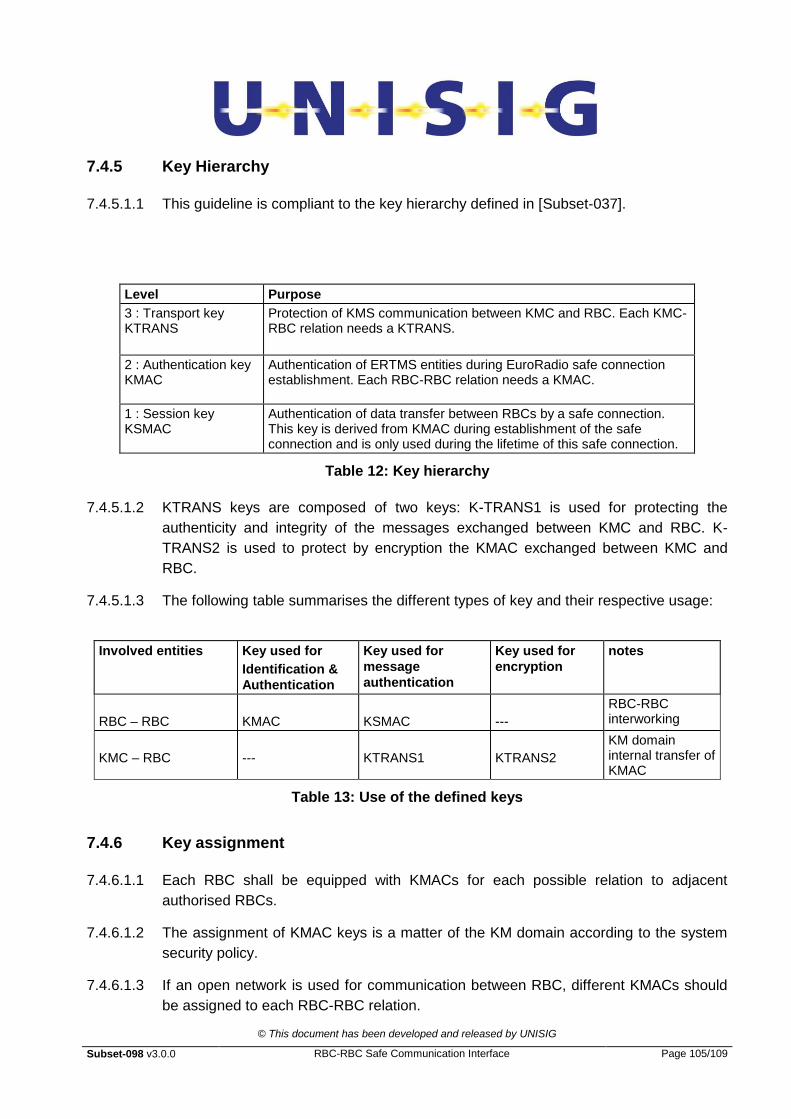
© This document has been developed and released by UNISIG
Subset-098 v3.0.0 RBC-RBC Safe Communication Interface Page 105/109
7.4.5 Key Hierarchy
7.4.5.1.1 This guideline is compliant to the key hierarchy defined in [Subset-037].
Level Purpose
3 : Transport key KTRANS
Protection of KMS communication between KMC and RBC. Each KMC-RBC relation needs a KTRANS.
2 : Authentication key KMAC
Authentication of ERTMS entities during EuroRadio safe connection establishment. Each RBC-RBC relation needs a KMAC.
1 : Session key KSMAC
Authentication of data transfer between RBCs by a safe connection. This key is derived from KMAC during establishment of the safe connection and is only used during the lifetime of this safe connection.
Table 12: Key hierarchy
7.4.5.1.2 KTRANS keys are composed of two keys: K-TRANS1 is used for protecting the
authenticity and integrity of the messages exchanged between KMC and RBC. K-
TRANS2 is used to protect by encryption the KMAC exchanged between KMC and
RBC.
7.4.5.1.3 The following table summarises the different types of key and their respective usage:
Involved entities Key used for
Identification &
Authentication
Key used for
message
authentication
Key used for
encryption
notes
RBC – RBC
KMAC
KSMAC
---
RBC-RBC interworking
KMC – RBC
---
KTRANS1
KTRANS2
KM domain internal transfer of KMAC
Table 13: Use of the defined keys
7.4.6 Key assignment
7.4.6.1.1 Each RBC shall be equipped with KMACs for each possible relation to adjacent
authorised RBCs.
7.4.6.1.2 The assignment of KMAC keys is a matter of the KM domain according to the system
security policy.
7.4.6.1.3 If an open network is used for communication between RBC, different KMACs should
be assigned to each RBC-RBC relation.
© This document has been developed and released by UNISIG
Subset-098 v3.0.0 RBC-RBC Safe Communication Interface Page 106/109
7.4.6.1.4 In case of closed networks, a unique KMAC may be assigned to all RBC-RBC relations
inside a KM domain.
7.4.6.1.5 The KMAC may be installed in RBCs in different KM domains: in the home KM domain
and any foreign KM domain. KMAC generation and assignment has to be agreed
between KM domain administrators. The exchange of KMAC via KM domain border is
specified by [Subset-038].
7.4.7 Basic KM Functions
7.4.7.1 List of functions
7.4.7.1.1 In order to allow perform secure and consistent key exchange between KMC and RBC
any key management system shall support the following functions:
Generate and validate KTRANS
Distribute KTRANS
Generate and validate KMAC
Distribute KMAC
Update KMAC
Delete KMAC
Archive keys and KM transactions
Note: Exchange of RBC KMAC with another KMC is out of scope for this guideline (see
Subset-038).
7.4.7.2 Generation and validation of KTRANS and KMAC
7.4.7.2.1 Only authorised persons and processes in a well-defined organisation and secure
environment shall generate keys for encryption and decryption or for authentication.
The keys should be generated randomly to prevent possible prediction.
7.4.7.2.2 All keys generated shall be checked to guarantee that they are not weak or semi-weak.
7.4.7.2.3 KTRANS and KMAC generation and validation shall be performed by the KMC
according to security requirements of interoperable ERTMS applications. Specific
technical solutions do not need harmonisation (provided security is ensured).
7.4.7.3 Distribute KTRANS
7.4.7.3.1 The distribution of keys in a KM domain shall take place between the KMC and RBC.
The theft or loss of key material shall be detected and unauthorised persons shall not
be able - or only with a very high effort - to modify keys.
7.4.7.3.2 The delivering KMC Administrator shall indicate which RBC-RBC relation that KTRANS
is intended for.

© This document has been developed and released by UNISIG
Subset-098 v3.0.0 RBC-RBC Safe Communication Interface Page 107/109
7.4.7.3.3 The receiving RBC shall confirm reception and take the necessary action to put the
KTRANS in operation.
7.4.7.3.4 The key shall be sent confidentially and is installed in the RBC by some staff
intervention.
7.4.7.4 Distribute KMAC
7.4.7.4.1 The delivering KMC Administrator shall indicate which RBC-RBC relation that KMAC is
intended for.
7.4.7.4.2 The receiving RBC shall confirm reception and take the necessary action to put the
KMAC in operation.
7.4.7.4.3 The key shall be sent confidentially by encryption with KTRANS2.
7.4.7.4.4 Key installation in RBC entities shall be under the responsibility of the KMC. It shall be
performed in a secure way and include all related key information.
7.4.7.4.5 Keys shall be stored in such a way that they remain authentic and confidential.
7.4.7.5 Update KMAC
7.4.7.5.1 The KMC Administrator decides when it is appropriate to update the KMAC. The
decision to update a key is taken according to a predefined key renewal plan or in case
of detection of hazardous situations (loss of confidentiality).
7.4.7.5.2 It should be possible to update KMAC during both maintenance and normal operation.
Note 1: updating during maintenance is intended for introduction or removal of RBC
entities.
Note 2: updating during operation is intended for non-interruptible entities like RBCs.
7.4.7.6 Delete KMAC
7.4.7.6.1 Key deletion shall be under the responsibility of the KMC domain. It shall be performed
in a secure way and include all related key information.
7.4.7.6.2 All possible copies of the key material shall be deleted including installed keys in RBCs
except the key archive under KMC responsibility.
7.4.7.6.3 The KMC Administrator shall be able to initiate key deletion.
7.4.7.6.4 The RBC shall confirm to the originator of the request that the key deletion has been
completed.
7.4.7.7 Archive keys and KM transactions
7.4.7.7.1 All keys, key related material and associated key transactions shall be archived by the
KMC in an authentic and confidential way, including:
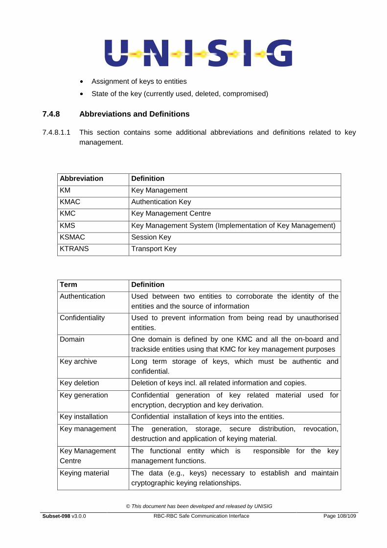
© This document has been developed and released by UNISIG
Subset-098 v3.0.0 RBC-RBC Safe Communication Interface Page 108/109
Assignment of keys to entities
State of the key (currently used, deleted, compromised)
7.4.8 Abbreviations and Definitions
7.4.8.1.1 This section contains some additional abbreviations and definitions related to key
management.
Abbreviation Definition
KM Key Management
KMAC Authentication Key
KMC Key Management Centre
KMS Key Management System (Implementation of Key Management)
KSMAC Session Key
KTRANS Transport Key
Term Definition
Authentication Used between two entities to corroborate the identity of the
entities and the source of information
Confidentiality Used to prevent information from being read by unauthorised
entities.
Domain One domain is defined by one KMC and all the on-board and
trackside entities using that KMC for key management purposes
Key archive Long term storage of keys, which must be authentic and
confidential.
Key deletion Deletion of keys incl. all related information and copies.
Key generation Confidential generation of key related material used for
encryption, decryption and key derivation.
Key installation Confidential installation of keys into the entities.
Key management The generation, storage, secure distribution, revocation,
destruction and application of keying material.
Key Management
Centre
The functional entity which is responsible for the key
management functions.
Keying material The data (e.g., keys) necessary to establish and maintain
cryptographic keying relationships.

© This document has been developed and released by UNISIG
Subset-098 v3.0.0 RBC-RBC Safe Communication Interface Page 109/109
Term Definition
KMC Administrator The KMC Administrator shall assume responsibility for all key
management administration functions within one domain.
Secure environment A secure place or a specially developed device. Under normal
circumstances it should not be possible for unauthorised persons
to read out any information from this special place or device.
Security The protection resulting from all measures, including
administrative, designed to prevent accidental or malicious
modification or disclosure of data. For key management the
protection generally guarantees confidentiality, authenticity and
integrity of keys.
Validity time Time for which the keys are valid.
7.5 Examples of Checksum results
Packet
Length
Version Appl.Type TSeqNum N/R Flag Packet
Type
Checksum
001E 01 1A 0000 01 01 1089
0021 01 1A 0000 01 02 F38E
0011 01 1A 0001 01 03 8D12
002A 01 1A 0002 01 03 C6E0
000B 01 1A 0003 01 04 57A0
Table 14 : Example of Checksum result – all values are in hex


![FIS for the RBC/RBC Handover...4.2.1.1 The RBC/RBC communication shall be established according to the rules of the underlying RBC-RBC Safe Communication Interface [Subset-098]. Further](https://static.fdocuments.net/doc/165x107/5e331307d520b57b5677b3fa/fis-for-the-rbcrbc-handover-4211-the-rbcrbc-communication-shall-be-established.jpg)