Subsea Well Controlwildwell.com/wp-content/uploads/Subsea-Well-Control.pdf · well control...
118
WILD WELL CONTROL SUBSEA WELL CONTROL
-
Upload
nguyenduong -
Category
Documents
-
view
215 -
download
2
Transcript of Subsea Well Controlwildwell.com/wp-content/uploads/Subsea-Well-Control.pdf · well control...

W IL D W E L L C O N T R O L
SUBSEA WELL CONTROL

W IL D W E L L C O N T R O L
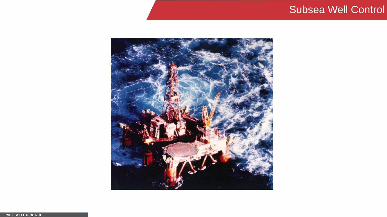
Subsea Well Control
You will learn that the basics of well control on a floating vessel are essentially the same as any other type of operation.
• Detect kick early, shut-in the well and circulate the kick out.
You will learn how water depth affects well control procedures and how it necessitates additional caution.
Learning Objectives
W IL D W E L L C O N T R O L
Subsea Well Control
WC equipment is basically the same,
but you will learn that there are
differences in the equipment, amount
of equipment and control of the
equipment.
• Risers and associated equipment.
• BOP stack, control lines, choke
and kill lines.
You will learn about and be able to
perform additional calculations for
friction and water depth concerns.
Learning Objectives

W IL D W E L L C O N T R O L
Subsea Well Control

W IL D W E L L C O N T R O L
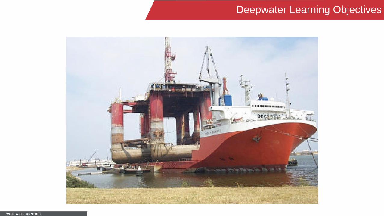
Deepwater Learning Objectives
Riserless returns
Riserless drilling
Kick tolerance
Choke and kill lines
Drilling fluids
Frictional concerns
Kick detection
Tripping
BOP cleanout
Hydrate prevention and removal
Lost circulation
Underground blowouts
Other considerations
Learning Objectives
W IL D W E L L C O N T R O L
Deepwater Learning Objectives

W IL D W E L L C O N T R O L
Subsea Well Control
The Subsea BOP stack and BOP related equipment are larger and more complex than most surface arrangements.
Due to the remoteness and extra time/expense in pulling the stack, additional considerations and extra
backup arrangements are provided.
Spudding initially performed through a temporary guide base until casing can be run and permanent guide base installed.
Overview

W IL D W E L L C O N T R O L
Subsea Well Control
During well control events, returns are routed through choke and kill lines extending from the Subsea BOP back to the kill manifold on surface.
• Additional friction must be
factored in procedures and calculations.
o Effect on formations.
o Start up considerations.
o Effect of gas, gas/mud, and mud flowing into lines.
Overview

W IL D W E L L C O N T R O L
Subsea Well Control
Water depth and geology are challenges that require additional equipment, procedures and training.
• Shallow water, shallow gas zones.
• Effect of fluid in riser vs. water depth.
• Diverter systems and diverters.
• Hydrates.
Overview

W IL D W E L L C O N T R O L
Subsea Well Control
W IL D W E L L C O N T R O L
Subsea Well Control

W IL D W E L L C O N T R O L
Shallow Flow Considerations
• Although all activities can be
dangerous, the first part of the well
can be hazardous.
Temporary guide base in place and
often no casing set.
If casing is set the well may not be
able to contain shut-in pressures.
- Riserless interval = no
formation control.
- Diverting when riser installed.

W IL D W E L L C O N T R O L
Shallow Flow Considerations
Main concern is shallow flow.
- Avoidance is main defense.
In unfamiliar areas a pilot hole may
be drilled.

W IL D W E L L C O N T R O L
Pilot Holes
The advantages of a pilot hole, slim hole or test well include:
• Easier and quicker to drill.
- Formation evaluations and test studies can be done quicker.
• With a smaller hole, drill gas is reduced.
• With a smaller annular volume, kicks can be circulated quicker.
• Decreased flow potential than in larger holes.
• Circulating ECD may bring kicking well into control.

W IL D W E L L C O N T R O L
Shallow Flows
Shallow water and gas flows:
• Usually the flow is either all gas or all water.
• May require MW in excess of fracture to contain.
• Hole erosion and loss of template, temporary guide base possible.
• Post cementing annular flow.
Main defense by planning and avoidance of these zones.
Procedures must be known, practiced and readily implemented.

W IL D W E L L C O N T R O L
Shallow Flows
Precautions and Considerations:
• Crewmembers should constantly be checking for changes in flow.
• Fluid should be premixed and handy if it is necessary.
• Anchors on moored vessels should be prepared for release if an emergency were to occur. There
should be a set move-off plan. Weather conditions should be monitored in order to adjust the move-off
plan as a result of change in wind direction/speed.

W IL D W E L L C O N T R O L
Reasons for Shallow Flows
There are several reasons for shallow flow:
• Over-pressured zones.
- Trapping and pressuring fluids by overburden loading.
• Under-compaction.
• Artesian effects.
• Formations formed by unstable currents carrying sediments.

W IL D W E L L C O N T R O L
Reasons for Shallow Flows
Gas:
• If migrating gas is trapped by a barrier, shallow gas may be accumulated in sands that are over-
pressured at the top of the sand.
• The force driving the shallow sand is almost always a result of seawater.
• Thus, the pressure at the base of the sand is equal to the hydrostatic pressure of seawater at that
depth.

W IL D W E L L C O N T R O L
Reasons for Shallow Flows
Shallow Formation Gas Hydrates:
• Where the potential for gas hydrates exist, precautions should be used for fluids in the choke and kill
lines.
• Formation gas, in hydrate form, can occur due to:
- Deeper water.
- Colder temperatures.
• Complications when encountering formation hydrates:
- Rapid expansion when cuttings circulated and hydrate to gas phase change occurs.
- Can reduce HP in riser and unload portion of riser. Kick may ensue.

W IL D W E L L C O N T R O L
Water Depth and Formation Fracture
As water depth increases there is an increase in potential for lost circulation and formation
damage/fracture.
“Thin margin” is the term used to describe the decreased margin between pore pressure and
fracture gradient.

W IL D W E L L C O N T R O L
Water Depth and Formation Fracture
W IL D W E L L C O N T R O L
Water Depth and Formation Fracture
As a result of the thin margin, any pressure over that of seawater placed on the formation may
result in formation fracture.
• This is especially true during the first interval of drilling.
• A riser cannot be used because of the increased density of a gel-water slurry and cuttings circulated up
the riser to the shaker.

W IL D W E L L C O N T R O L
Water Depth and Formation Fracture

W IL D W E L L C O N T R O L
Water Depth and Formation Fracture
Well may not contain pressure and can broach from casing shoe to mudline.
Possibility of gas surfacing underneath rig:
• Chances decreases with increase in water depth and current.
• Rig may loose some buoyancy in water which will lower the freeboard, but will not sink from gas plume.
- Down flooding of compartments possible which may create ballast control problems.
- Gas accumulations around rig potentially hazardous.

W IL D W E L L C O N T R O L
Water Depth and Formation Fracture

W IL D W E L L C O N T R O L
Kick Detection – Riserless Interval
• Primary kick indicators
ROV
Pump pressure decrease
String weight change
Sightings of gas/plume at surface

W IL D W E L L C O N T R O L
Well Control Options During Riserless Interval
Limited options – low chance of regaining control.
• Pump heavy mud.
• Increase pump rate.
• Move off location if gas endangers rig.
• Pull pipe out well and wait for zone depletion.

W IL D W E L L C O N T R O L
Diverter Systems
Diverter systems consist of a diverter preventer and lines to route gases and formation fluid
coming up the riser away from the rig area.
• Used when the riser is installed.
- Shallow flows where well cannot be shut-in.
- Gas in riser.
Diverter lines should be routed with minimum of turns/bends. Lines, as large as practical should
be used (12” or greater on floaters).

W IL D W E L L C O N T R O L
Diverter Systems
The diverter annular preventer must close within 45 seconds, per API RP53 and 16D.
The diverter line (s) must open prior to the preventer closing.

W IL D W E L L C O N T R O L
Diverter Systems

W IL D W E L L C O N T R O L
Diverting
Flow check considerations.
• If an unplanned increase in flow is suspected, the diverter should be aligned, pumps shut down and flow
checked.
• If it is obvious that the well is unloading or if a shallow flow is anticipated, then shutting down the pumps
and making a flow check may not be necessary.
W IL D W E L L C O N T R O L
Diverting
If diverter procedures must be taken, there are several options.
• The first step is to always close diverter packer and divert downwind, closing the lines to the fluid
handling system.
• The wind direction and downwind diverter line should be checked and selected at least tourly, or as
conditions warrant.
• Once this is accomplished, the options are to use mud, water or not pump at all.
Proper planning, training and drills must be performed prior to intervals where diverter use may
be used.

W IL D W E L L C O N T R O L
Diverting
Diverter Procedure with Water:
• The advantages of using water is that the floating rig has an unlimited supply – align pump manifold to
sea water suction and then shut off mud suction, maximize pump rates. The increased pump rates
maximize ECD effect, but can increase erosion.
• Water may keep the returns slightly less flammable than without pumping.
• Disadvantages include rig power is on and flammable conditions.
W IL D W E L L C O N T R O L
Diverting
Diverter Procedure with Mud:
• Mud, while an option is not very practical.
• Several hole “volumes” of mud must be readily available if this option is used.
• More ECD than using seawater. Again, hole erosion quickly negates the benefits.
W IL D W E L L C O N T R O L
Bridging Documents
“What is expected and what actually happens are often very different.”
A bridging document, i.e., a detailed procedure manual must be reviewed by the operator and
contractor prior to commencing the operation.
• Often there are minor and major differences on how to handle situations.

W IL D W E L L C O N T R O L
Bridging Documents
• Conflicting policies and procedures must be resolved and only one solution used.
• The crew must be trained in the proper procedure.
• Diverting is an excellent example of why these must be in place.
- Flow check?
- Divert and desert?
- Fight and flight?
- To pump or not to pump?
If pumping is an option, what will you pump?

W IL D W E L L C O N T R O L
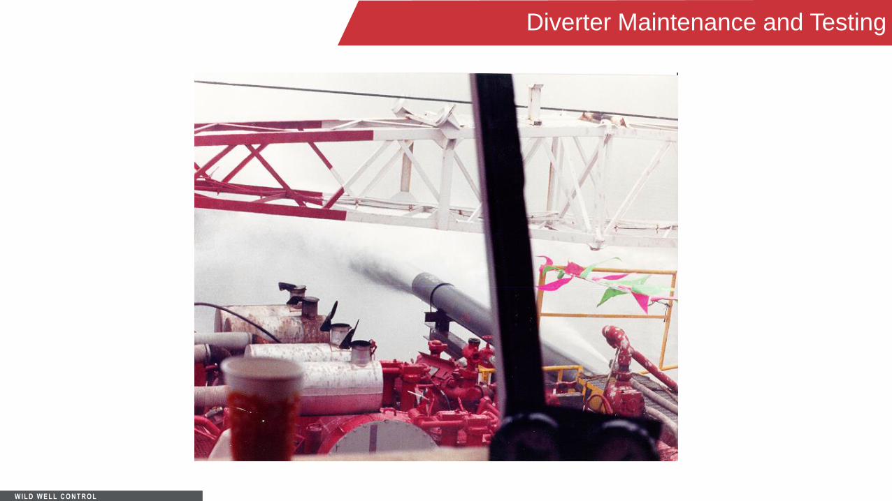
Diverter Maintenance and Testing
Often not practical to pressure diverter system.
Function test daily.
After diverter use to control flow, an inspection of the entire system should be made.
• Any repairs should be supervised by manufacturer’s representative.
W IL D W E L L C O N T R O L
Diverter Maintenance and Testing
W IL D W E L L C O N T R O L
Riser Collapse
Risers have limitations. If gas evacuates the riser a pressure differential occurs that may cause
collapse.
• Under normal operations mud in the riser creates an overpressure versus the water’s pressure on the
outside.
• If gas voids all or a portion of the riser, this is reversed. Collapse pressures are less than burst pressure.

W IL D W E L L C O N T R O L
Riser Collapse
• If gas voids all or a portion of the riser, this is reversed. Collapse pressures are less than burst pressure.
• The maximum water depth that a riser can be run in empty before collapsing should be calculated and
appear on rig statistical data.
A riser dump valve can be run and should be opened once its predetermined pressure differential
is about to be reached in order to allow seawater in the riser and prevent collapse.

W IL D W E L L C O N T R O L
Riser Collapse

W IL D W E L L C O N T R O L
Riser Loss
If the riser is disconnected, parted or lost, the hydrostatic pressure exerted at the BOP stack is
decreased.
The drop in hydrostatic is equivalent to the hydrostatic differential between the fluid that was in
the riser and seawater.
• Additionally, there is a loss of the mud’s hydrostatic pressure from sea level to the flow line.
Pressure Differentialpsi = ([Fluid Wt in Riserppg – Seawater Wtppg] x Water Depthft
x 0.052) + (Fluid Wtppg x Air Gapft x 0.052)

W IL D W E L L C O N T R O L
Emergency Riser Disconnect
Plans should be established for procedures to disconnect the riser in case of emergency.
The riser system has tremendous stored energy in the tensioner cylinders and cables and from
strain energy in the riser itself. This must be properly de-energized or a recoil potential may
occur.

W IL D W E L L C O N T R O L
Emergency Riser Disconnect
Procedures for disconnecting the riser include:
• Hang off the drill pipe on pipe rams
• Shear the drill pipe
• Close blind or blind/shear to seal wellbore
• Dissipate any energy in the riser/riser tensioning system
• Disconnect the LMRP
• Clear the BOP with the LMRP
• Safely capture the riser
W IL D W E L L C O N T R O L
Emergency Riser Disconnect
Disconnect procedures should be posted for the following:
• Normal drilling operations
• Bit above BOP stack
• Drill pipe in stack
• BHA in stack
• Well control situations
• Casing in the BOP

W IL D W E L L C O N T R O L
Emergency Riser Disconnect

W IL D W E L L C O N T R O L
Kick Detection With Risers and Stacks
Kick detection techniques between 500’ and 15,000’ water depths are basically the same.
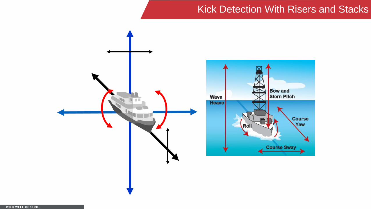
• Vessel motion must be taken into account.
- Wave conditions, heave, pitch and roll.
LWD/MWD/PWD technologies.
Crew training.
Alertness and action are crucial!

W IL D W E L L C O N T R O L
Kick Detection With Risers and Stacks
The effect of pitch, roll, and heave must be taken into consideration when monitoring return flow
and changes in pit level.
• A set range of change must be established. Deviations from this range signals the driller that a problem
may be occurring.
• Crane loading and movement may affect settings.
W IL D W E L L C O N T R O L
Kick Detection With Risers and Stacks
Perhaps the best device for kick detection or lost circulation is the flow sensor.
• The alarm should be set for a range of 25 to 50 gal/min flow change above the vessel’s range
movement.
• Pit volume totalizer alarms should be set at a range of +5.0 to – 5.0 bbls.
W IL D W E L L C O N T R O L
Kick Detection With Risers and Stacks
W IL D W E L L C O N T R O L
Kick Detection With Risers and Stacks
Any transfer of fluid must be approved and reported to the driller, toolpusher, company rep, and
ballast control. The same holds true for any additions of materials or fluid.
Another tool used for kick detection is standpipe pressure.
• Alarm should be set at a range of 50 to 100 psi above circulating pressure.
MWD/LWD/PWD tools also can be used to detect kicks.
W IL D W E L L C O N T R O L
Kick Detection With Risers and Stacks
Correct procedure must be used to shut the well in once a kick is detected. Company policy
should also dictate to close the diverter packer after shutting the well in, and perform a flow
check on the riser to detect gas in the riser.
• If flow is detected in the riser, there is a potential that either the kick has migrated above the LMRP or
that the preventer is leaking.
• Keep diverter closed and close another preventer on the BOP stack.
- If riser is still active allow gas to migrate. Use of booster pump is usually not advised.

W IL D W E L L C O N T R O L
Kick Detection With Risers and Stacks
Space Out/Hang Off Procedure:
1. Upper annular is used to shut in well.
2. If exact spacing is unknown due to a trip or other factors, pull pipe slowly and monitor weight indicator
and the accumulator flow meter. The weight should slightly increase as a tool joint is stripped through
the annular. Also, the annular will require more fluid as TJ goes through in order to maintain closure
pressure against the pipe body.

W IL D W E L L C O N T R O L
Kick Detection With Risers and Stacks
3. Finally, spacing can be calculated.
4. Once this is calculated, close the hang off rams.
5. Lower the pipe gradually and hang off using the drill string compensator and close the ram locks.
Bleed pressures off between the closed ram and annular if possible. Then open the annular.

W IL D W E L L C O N T R O L
Muds
The temperature stability, i.e., hot and cold properties must be taken into account:
• The effect of cold or freezing temperatures, as well as hydrates forming in the choke and kill lines must
be taken into account.
Viscosity crucial – Pumps should be brought on line gradually, as the force required to break
“gels” may also increase pressures throughout the well.
• Slow rotation will also help to break gels.

W IL D W E L L C O N T R O L
Oil Based Mud/Synthetic Oil Based Mud
Considerations when using OBM/SOBM:
• Gas solubility.
- Gas may dissolve in the oil solution making kick detection more difficult.
- The “bubble point” where gas breaks out of solution may be in the riser, resulting in rapid
expansion and potential unloading.

W IL D W E L L C O N T R O L
Kick Tolerance
Typically lower due to water depth.
Deviation from standard calculations to take stringing out of gas “bubble” and washouts into account.
Best solution is to prevent kick, or at very least minimize kick size – alarms and crew training crucial.

W IL D W E L L C O N T R O L
Bubble Point
• Gas stays in solution until bubble
point pressure is reached.
• Rapid expansion ensues.

W IL D W E L L C O N T R O L
Potential Kick in Riser
Possible Influx/Gas in riser when kick detected.
As water depth increases, possibility for kick in riser also increases.
Kick on bottom vs gas expansion in riser – can look the same.

W IL D W E L L C O N T R O L
Potential Kick in Riser
Simultaneous active riser and well kill options.
• Potential exists for gas in riser during well control event when shut procedures initiated.
Shut in procedures should include diverting procedures.
Diverter/riser limitations:
• Do not pump up gas in active riser.

W IL D W E L L C O N T R O L
Ballooning Formations
Treat as kick until formation behavior known.
• Measure mud losses to formation during circulation.
• Measure mud gains (flowback) from formation with pumps shut down.
• Establish difference between flowback and drain-back.
Establish trend.

W IL D W E L L C O N T R O L
Tripping Out
Pump out of hole (safest approach).
• Technique used with thin margins.
• Pump at rates at least equal to pipe displacement.
• Minimize connection time (ECD loss and sticking).
• Stop when motor (if any) is in casing.
Accurate trip records.
Tripping vs weather and seas.
Use re-circulating trip tank, monitor it and keep accurate records.

W IL D W E L L C O N T R O L
Tripping Out
Prior to trip, perform swab test.
• When circulating, 1000’ prior to bottoms up reaching BOP stack, close BOP and circulate through
choke/kill lines and through choke and mud gas separator.
• Evaluate bottoms up returns for indications of gas or formation fluids.

W IL D W E L L C O N T R O L
Tripping In
Lined-up to trip tank – should be circulating across hole and continuously monitored.
Cooling temperature effects on mud vs surge pressure.
Break circulation frequently.
Circulating from casing shoe to bottom may be considered.

W IL D W E L L C O N T R O L
Choke/Kill Lines
Larger diameter lines minimize friction pressure loss.
Multiple lines also reduce the effect of circulating friction.
Choke line friction vs formation fracture:
• Lower pump rates and/or using both choke and kill lines may be necessary.
W IL D W E L L C O N T R O L
Choke/Kill Lines
Loss of hydrostatic and CLFP when gas enters.
• As gas enters the chokeline at the BOP stack, a loss of hydrostatic and reduction in CLFP occurs. This
event has a potential to take a 2nd kick if pressures are not properly maintained.
• Similarly, when mud following gas enters the chokeline at the BOP, a rapid gain in hydrostatic and
increase in CLFP occurs. This event has a potential to cause lost circulation if pressures are not
properly maintained.

W IL D W E L L C O N T R O L
Friction
Mud properties critical.
Cuttings may increase ECD, mud weight to near fracture weight.
MWD/PWD tools necessary in critical wells to assess effect of friction on well.

W IL D W E L L C O N T R O L
Friction-CLFP (Choke Line Friction Pressure)
Choke/Kill Line Friction Pressures must be taken into account. If ignored CLFP may increase
pressure in the well and cause formation damage/breakdown.
CLFP should be determined:
• Prior to drill out each casing string.
• Mathematically can be corrected for MW changes.
- Should be retaken if rheology changes.
• Several procedures for determining CLFP.

W IL D W E L L C O N T R O L
CLFP and Well Control Operations
During the start up period in well control, from shut in to circulating rate, this pressure must be
subtracted from choke pressure.
• Alternately, if the kill line is not used for circulating, it may be used as a “monitor” line. Maintain the
monitor line constant during pump start up.

W IL D W E L L C O N T R O L
CLFP and Well Control Operations
Kill rate and CLFP evaluation:
• Use choke or choke and kill lines?
• Deviation from standard well control methods.
- ICP, FCP sometimes cannot be reached even with chokes full open. Have to know why and when
to begin using choke and what pressures are obtainable.
W IL D W E L L C O N T R O L
Choke/Kill Line System and Friction
Choke Line Friction Pressure (CLFP).
• The friction pressure to circulate through either or both choke and kill lines must be known.
• This pressure may contribute to fluid losses and/or formation failure.
• This pressure is “lost” before the pressure is seen on the choke line gauge, but nevertheless is felt
throughout the circulating system.

W IL D W E L L C O N T R O L
Choke/Kill Line System and Friction
• The pressure, expressed in MW (ppg) may be expressed as:
EMW (ppg) = CLFP pressure (psi) ÷ Csg. depth (ft)
÷ 0.052 + OMW (ppg)
*There are several methods to determine Choke Line Friction Pressure.

W IL D W E L L C O N T R O L
Choke/Kill Line System and Friction
Choke Line Friction Test Method 1
• Circulate down DP at pre-determined pump rate(s), record.
• Open Choke line valves.
• Close BOP.
• Circulate down DP, up choke line at pre-determined rates.
– The increase in circulating pressures is the CLFP. Repeat the same through both choke and kill
lines.
W IL D W E L L C O N T R O L
Choke/Kill Line System and Friction
Choke Line Friction Test Method 2
• Pump down the choke and/or kill lines at pre-determined rates.
• The circulating pressure through the line (s) is the CLFP.
W IL D W E L L C O N T R O L
Choke/Kill Line System and Friction
Choke Line Friction Test Method 3
• Circulate across stack.
• With choke/kill lines open, close upper annular preventer and preventer below circulating outlet.
• Circulate at pre-determined rates.
• Divide the circulating pressure by 2 to find the CLFP.
W IL D W E L L C O N T R O L
Choke/Kill Line System and Friction
Choke Line Friction Test Method 4
• Mathematical correction (if mud’s rheological properties have not changed).
New CLFP (psi) = Old CLFP (psi) X New (ppg) / Old (ppg)
*Note: Procedures may be performed with well shut in prior to circulating a kick. This
ensures proper pressures are used and with current MW in choke/kill lines.

W IL D W E L L C O N T R O L
Choke/Kill Line System and Friction

W IL D W E L L C O N T R O L
Startup Procedure
Static vs Dynamic
When bringing the pump up to kill rate speed, CLFP must be taken to account.
• If CLFP isn’t taken into account, formation damage/breakdown may occur.
• Calculations show that friction increases to approximately the square of the rate.
• To keep things simple, which is always preferred during well control operations, this means that for
every doubling in pump rate, friction is squared.

W IL D W E L L C O N T R O L
*Once at full kill rate speed, the remaining pressure should be taken off and the DP schedule observed.
Startup Procedure

W IL D W E L L C O N T R O L
Startup Procedure
Alternate Start-Up Kill Procedure – Critical Applications:
Open the choke.
• Bring the pumps smoothly up to kill rate speed.
• Adjust circulating casing pressure to the original shut in value minus the CLFP value.
• Observe DP pressure and adjust accordingly.
*Note: This may allow additional influx, but will minimize formation damage.
W IL D W E L L C O N T R O L
Maintaining Correct Pressure
Pressure changes as gas enters the choke line:
• Gas enters the choke line.
• Displaces mud – results in loss of mud’s hydrostatic friction pressures.
• Rapid gas expansion can offset loss of hydrostatic.
• Use DP pressure and try to keep with changes by adjusting pressure on choke.
• Once gas begins to exit choke, expect rapid drop in pressure, compensate by adjusting choke to last
known, reliable pressure reading.
• Check DP pressure and adjust as necessary.

W IL D W E L L C O N T R O L
Maintaining Correct Pressure
Pressure Gain as Mud Follows Gas in the Choke Line:
• Once gas is exiting choke, expect gains in hydrostatic and friction pressures as mud displaces gas in
choke line.
• Will rapidly increase pressure down hole and must be adjusted quickly to offset.
• Refer to DP pressure for additional adjustments.

W IL D W E L L C O N T R O L
Gas Trapped in Stack and Clearing the Riser
There is always the potential for gas trapped under a closed BOP.
• Depending on water depth and BOP arrangement, this may present the possibility of several barrels
of trapped volume.
• If gas occupies this area and is released to the riser, it could expand to hundred of barrels of gas in
the riser system.
• This can displace enough riser mud to drop the fluid level to a point allowing another kick.
W IL D W E L L C O N T R O L
Gas Trapped in Stack and Clearing the Riser
To minimize the impact:
• Isolate the trapped gas by closing a lower preventer.
• Circulate salt water/ethanol to the BOP.
• Align and open choke to the BOP.
• Let the gas expand.
• If possible, once the expansion slows, open the BOP to flush the gas to surface.
• Displace fluid in riser and choke/kill lines with kill fluid, check pressure below closed BOP and if none
exists, open BOPs.

W IL D W E L L C O N T R O L
BOP Cleanout (Trapped Gas)
In water depths greater than 3,000’ incidences of trapped gas inconclusive, but risk of trapped
gas may be reduced.
Techniques for sweeping BOP stack must be in place.
Techniques for sweeping riser must be in place.

W IL D W E L L C O N T R O L
Gas Hydrates
Hydrates are the combination of gas/water that form solid ice like structures at high pressures
and cool temperatures such as those found in Subsea BOP stacks.
Although hydrates may form at water depths over 3,000’, actual well reports have not proven the
concerns given.
There are charts available, hydrate formation curve, that show favorable conditions.

W IL D W E L L C O N T R O L
Typical Hydrate Formation Curve
Typical Hydrate Formation Curve

W IL D W E L L C O N T R O L
Hydrates Prevention
Inhibiting mud system – what can work:
• Glycol and other inhibiting chemicals in depths over 4,000’.
• Saturated salt mud systems (23% by weight) in water less than 4,000’.
Best prevention method is to keep fluid moving!
• If shutdown, close rams directly above circulating outlet.
After kick, remove any trapped gas quickly.

W IL D W E L L C O N T R O L
Hydrates Removal
Once hydrates form it is difficult, time consuming, and expensive to dissolve.
Methods to remove hydrates include:
• Heat or chemical dissolution
• Methanol
• Coil tubing

W IL D W E L L C O N T R O L
Lost Returns
Lost Circulation problems increased by:
• Circulation friction (ECD, APL, CLFP).
• Cuttings loading in annulus.
• Use of booster line (additional friction).
• Well should be designed keeping friction in mind.

W IL D W E L L C O N T R O L
Other Complications/Considerations
P&A procedures.
Choke and kill line “Separator” effect.
Fluids left in choke and kill lines.
• Change out several times daily.
MGS Bypass/overboard:
• It may become necessary to bypass the MGS.
• Pressure in the MGS must be monitored using low pressure gauges.
A small strip tank should be utilized if stripping operations are necessary.

W IL D W E L L C O N T R O L
Subsea Equipment Overview
Generally, the first tool run in the subsea environment is the guide base.
• This instrument is a “base” that “guides” the drillstring, casing, and other equipment into the drilled hole.
• The guide base and its components may be guideline landed or guidelineless depending on depth of
water and type of rig.
W IL D W E L L C O N T R O L
Subsea Equipment Overview
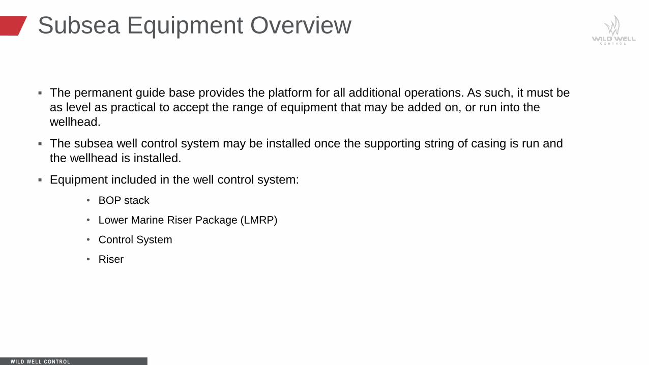
The permanent guide base provides the platform for all additional operations. As such, it must be
as level as practical to accept the range of equipment that may be added on, or run into the
wellhead.
The subsea well control system may be installed once the supporting string of casing is run and
the wellhead is installed.
Equipment included in the well control system:
• BOP stack
• Lower Marine Riser Package (LMRP)
• Control System
• Riser

W IL D W E L L C O N T R O L
Subsea Equipment Overview

W IL D W E L L C O N T R O L
Subsea Equipment Overview
W IL D W E L L C O N T R O L
Subsea Equipment Overview

W IL D W E L L C O N T R O L
Subsea Equipment Overview
• Riser Joint
• 2 million lbs tension.
• Up to six 5” auxiliary 15,000 psi lines.
• Replaceable seal subs.
• Urethane clamps reduce weight and
maintenance.

W IL D W E L L C O N T R O L
Subsea Equipment Overview
• Riser Connection
• Bolts retained in top flange.
• Nuts in upper and lower flanges.
• No loose parts.
• Make-up faster than moving next
riser joint to vee door.

W IL D W E L L C O N T R O L
Subsea Equipment Overview
• Telescoping Joint
• Absorbs vertical movement of rig
relative to stack.
• Low pressure packer system.
• Supports BOP weight in either
extended or retracted position.
• Typically lowest pressure device of
riser system.
W IL D W E L L C O N T R O L
Subsea Equipment Overview
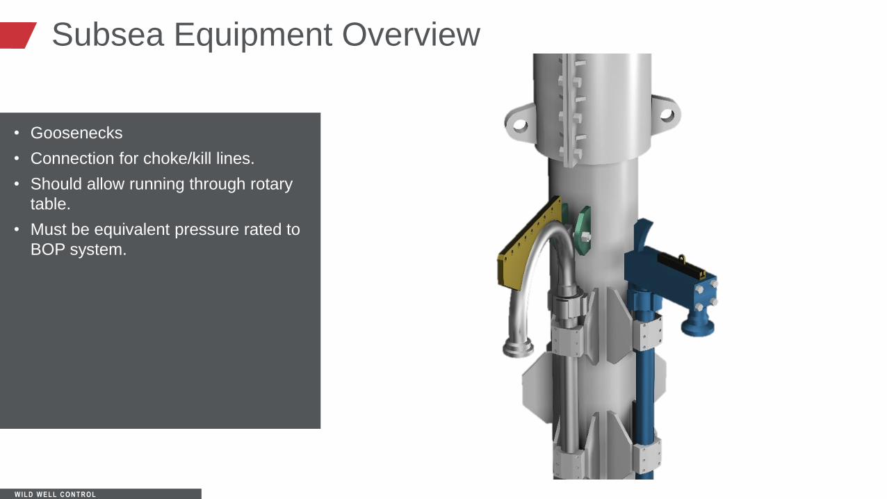
• Goosenecks
• Connection for choke/kill lines.
• Should allow running through rotary
table.
• Must be equivalent pressure rated to
BOP system.

W IL D W E L L C O N T R O L
Subsea Equipment Overview
• Tensioning Ring
• Features:
Eliminates need to manually re-
connect tensioner lines and
goosenecks.
Hydraulically actuated.
Choke/kill lines remotely made up.
W IL D W E L L C O N T R O L
Subsea Equipment Overview
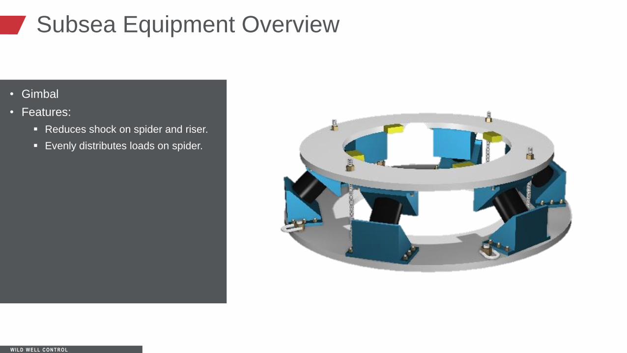
• Gimbal
• Features:
Reduces shock on spider and riser.
Evenly distributes loads on spider.

W IL D W E L L C O N T R O L
Subsea Equipment Overview
• Riser Spider
• Features:
Remote operation of riser dogs
Split-design for ease of handling.
W IL D W E L L C O N T R O L
Subsea Equipment Overview
The BOP stack is attached to the wellhead by a connector, such as a collet connector.
• This connector must provide a working pressure that is at least equal to or greater than the BOP stack’s
rated working pressure.
Additional sets of rams or dual-purpose rams may be utilized for additional versatility and back-
up.
• Problem: adding more rams or components raises the height of the stack and may cause handling and
running problems.
W IL D W E L L C O N T R O L
Subsea Equipment Overview
• Blind/shear and variable bore rams are commonly used. These may minimize or eliminate the need to
pull the stack for replacement or repair.
• Sometimes, two sets of blind/shear rams are used in order to back up seals in case of an unplanned
disconnection.
Another connector is located towards the top of the BOP stack that connects the LMRP.
• This connector limits using the upper annular preventer to its pressure rating.
W IL D W E L L C O N T R O L
Subsea Equipment Overview
Control system:
• Consists of two sets of controls, yellow and blue control pods, which are identically designed.
• Communication of surface to subsea equipment is linked by the control pods.
• The control pods consist of electric and/or hydraulic control lines that signal shuttle valves to trigger
functions on the BOP stack.
• Other pieces of equipment that are sometimes run into the subsea environment for various reasons are
accumulator bottles.

W IL D W E L L C O N T R O L
Subsea Equipment
The Subsea BOP system is more complex than surface mounted BOP’s.
Remote and duplicate functionality is provided for by “pods” or control systems.
A hydraulic, electric, or hydraulic/electric system (MUX) actuates BOP functions from surface
control panels.

W IL D W E L L C O N T R O L
Subsea Equipment
Complex arrays of hose bundles extend from surface to control pods (blue and yellow) that
function the BOPs. Two pods ensure more reliability in case one fails.
The depth and great water pressures necessitates that Subsea accumulators are pre-charged to
1,500 psi above the water’s hydrostatic. This ensures rapid functions.
• Consideration should be given to venting the pressure/fluid in the subsea accumulator bottles prior to
tripping the stack back to surface.
W IL D W E L L C O N T R O L
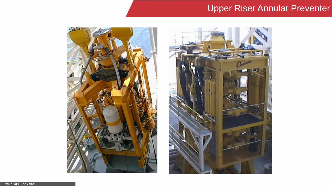
Upper Riser Annular Preventer
Once the permanent guide base is installed the annular preventer is an alternative to the diverter
system.
Shutting in the well versus diverting is usually the preferred option.
W IL D W E L L C O N T R O L
Upper Riser Annular Preventer

W IL D W E L L C O N T R O L
Placement of Rams/Outlets
The optimum place for a BOP outlet is below the upper annular, as part of the LMRP. This
minimizes the potential trapped gas and helps with the cleanout procedures.
The number and placement of outlets are usually designed for versatility of operations.
• The lowermost usually allows for monitoring well conditions if shut in on a lower ram.
• Cost and operational functions usually limit the number of outlets.
W IL D W E L L C O N T R O L
Moored vs DP Differences
DP vessels can “get off” location much quicker than moored vessels, however, contingency
procedures must be developed against “drive off” for DP MODU’s.
DP vessels also use guidlineless riser/control lines.
Both types can regulate how much tension and load is on the riser and BOP system.
It is critical to recognize and be able to adequately “de-energize” the force of recoil from the
tensioner system if a stack disconnect or riser separation occurs.

W IL D W E L L C O N T R O L
BOP Loading
Loading on the BOP stack is a function of the weight of the riser and it’s buoyancy in the sea
water (inside fluid weight and salt water gradient), as well as the tension placed on the riser with
the rig’s tensioner system.
Design limitations should be known and not exceeded.
W IL D W E L L C O N T R O L
Disconnects and Stabs
Emergency disconnects are rare, but can occur:
• Accidentally
• Due to weather conditions
• Well control events
• Remember about the riser recoil potential
Stabbing back into the BOP stack or C4 connection have been performed successfully.
• Use of ROV is necessary

W IL D W E L L C O N T R O L
Tips and Considerations
Often the density and fluid types in the choke, kill line, and riser, may be different than the fluids
in the wellbore. This can complicate well control, as additional calculations, volumes and
displacements must be considered.
ROV’s have many uses and can be used to override surface control functions.
Acoustic back up systems are also used to control pod functions in case of loss of
communication with the surface control lines.

W IL D W E L L C O N T R O L
Equipment Considerations
Closing times for the annular should not exceed 60 secs.
Closing times for pipe rams should not exceed 45 secs.
Response time for other functions should not exceed 45 secs.
The block function on control panels should illuminate when functioned to indicate that the
function is either locked in the open or closed position.
There are several types of control systems. Electric systems provide the fastest response time.
W IL D W E L L C O N T R O L
Accumulator Bottle Considerations
Accumulator bottles are part of the BOP stack to provide hydraulic power to more effectively
function the stack at great lengths from the control panel (s).
Accumulator bottles on the BOP stack must be charged to precharge pressures above the
hydrostatic of the salt water.
• If possible, consider venting these bottles prior to pulling the BOP stack.
• Hydraulic pilot lines charge the accumulator bottles to operating pressure. They do not provide direct
closing pressure.

W IL D W E L L C O N T R O L
Subsea Well Control
You learned the basics of well control on a floating vessel are essentially the same as any other type of operation.
• Detect kick early, shut-in the well and circulate the kick out.
WC Equipment is basically the same, but there are differences in the equipment, amount of equipment, and control of the equipment.
• Risers and associated equipment.
• BOP stack, control lines, choke, and kill lines.
You learned how water depth affects well control procedures and how it necessitates additional caution.
You learned about and are able to perform additional calculations for friction and water depth concerns.
Learning Objectives