Submitted to. the Univ'ersity o,f Cape Town Cape of University
138
University of Cape Town f I MULTIPiE EXPANSION REFRIGERATION CYCLES J A BROWNE September 1986 Submitted to. the Univ'ersity o,f Cape Town in partial fulfilment of the requirements for the degree of Master of Science in Engineering. SUPERVISOR Professor J Gryzagoridis Tho Un1Ycs:nt2y of Coe Town has been given tho right to ·reproduce this thesis In whole or In part. Copyright' Is held by the author.
Transcript of Submitted to. the Univ'ersity o,f Cape Town Cape of University

Univers
ity of
Cap
e Tow
n
f I
MULTIPiE EXPANSION REFRIGERATION CYCLES
J A BROWNE
September 1986
Submitted to. the Univ'ersity o,f Cape Town
in partial fulfilment of the requirements
for the degree of Master of Science in
Engineering.
SUPERVISOR
Professor J Gryzagoridis
Tho Un1Ycs:nt2y of Coe Town has been given tho right to ·reproduce this thesis In whole or In part. Copyright' Is held by the author.

Univers
ity of
Cap
e Tow
n
The copyright of this thesis vests in the author. No quotation from it or information derived from it is to be published without full acknowledgement of the source. The thesis is to be used for private study or non-commercial research purposes only.
Published by the University of Cape Town (UCT) in terms of the non-exclusive license granted to UCT by the author.

I, John Arthur Browne submit this thesis
in partial fulfilment of the requirements
for the degree of Master of Science in
En g i n e e r i n g . I c 1 a i m · t hat th is i s my
original work and that it has not been
submitted in this or any similar form for
any degree at any University.
J A BROWNE
Uriiversity of Cape Town
September 1986

i
ABSTRACT
The work describ~d in this thesis deals with some
the o re t i ca 1 and . p r act i ca 1 aspects of mu 1tip1 e
expansion vapour compression ref~igeration cycles.
Research on refrigeration cycles has concentrated
on the development of the single and two stage
vapour compression cycle, the absorption
refrigeration cycle and the development and
eva lua ti on of new refrigerants and absorbents.
This has occured to the extent that further improvements in the per£ o rman_ce of these cycles that can be economically implemented for small scale units are unlikely to be found.
This work undertook to carry out the following
i) A theoretical ~tudy of the multiple expansion
vapour compression cycle aimed at determining
the theoretical performance of the cycle and
comparing it to that of other commonly used
refrigeration cycles.
ii) An experimental study of a hybrid
refrigeration cycle which combined a multiple
expansion vapour
absorption cycle.
an indication
compression cycle with an
This study aimed to obtain
of the performance and
practical usefulness of· the cycle and to
prove that hybrid cycles can be operated
successfully. The cycle used dimethyl ether -
tetra ethylene glycol as the absorbent and
R22 as the refrigerant.

ii
The results obtained indicated that signifigant
improvements in performance are theoretically
possible with multiple expansion vapour
compression cycles. However considerable
development of a suitable means to achieve the
multiple compressions required for the cycle is
required.
The experimental work with the hybrid cycle showed
that multiple refrigerant expansions were possible
in practice. This successfully achieved the first
step in the production of a true multiple
expansion vapour compression cycle as studied
theoretically.
Finally it was found that the multiple expansion -
absorption cycle works satisfactorily in practice
but its low performance and high cost limit its
usefulness to special applications.
iii
ACKNOWLEDGEMENTS
The author would like to thank the following
people and organisations for their assistance with
this project :
Professor J Gryzagoridis for his project
supervision.
Mr. G F Browne for his assistance in manufacturing
the equipment and overcoming various practical
problems encountered with constructing and
commissioning the experimental apparatus.
Mr. L Watkins and the workshop staff of the
department of Meehan ica 1 Engineering for their
assistance with manufacturing the equipment.
Mr. V Appleton for ~is help with the photography.
The Council for Scientific and Industrial Research
for their sponsorship of this project by way of a
bursary award.

Abstract
Acknowledgements
Contents
List of Figures
List of Tables
List of Photographs
iv
CONTENTS
Page
i
iii
iv
vi
viii
viii
1 INTRODUCTION 1
1.1 A Brief History of Refrigeration 1
1.2 Basic Refrigeration Concepts 3
1.3 The Vapour Compression Refrigeration Cycle 5
1.4 ~he Vapour Absorption Refrigeration Cycle 8
1.5 Multiple Expansion Vapour Compression Cycles 12
2 THEORETICAL ASPECTS OF MULTIPLE EXPANSION CYCLES 19
2.1 Performance Loss Due to Flash Gas Formation 19
2.2 The Multiple Expansion Vapour Compression Cycle 22
2.3 The Multiple Expansion - Absorption Cycle 27
3 EXPERIMENTAL APPARATUS 35
3.1 General Description 35
3.2 The Expansion Column 39
3.3 The Generator 44 3.4 The Absorber 49
3.5 The Evaporator and Condenser 55
3.6 The Pump Unit 56
3.7 The Compressor Unit 57
3.8 Instrumentation and Data Measurement Methods 57 3.9 Experimental Methodology 59

v
4 RESULTS DISCUSSION AND CONCLUSION
4.1 Results
4.2 Discussion
4.3 Conclusions
REFERENCES
BIBLIOGRAPHY
APPENDIX A THEORY OF REFRIGERATION CYCLES
A.l The Carnot Refrigeration Cycle
A.2 The Single Stage Vapour Compression Cycle
A.3 Comparison of The v.c. Cycle With The Carnot cycle
A.4 The Two Stage v.c. Cycle With Intercooling
A.5 The Vapour Absorption Refrigeration Cycle
A.6 Maximum Theor~tical Performance of a Vapour
Asorption Refrigeration cycle
APPENDIX B THEORETICAL EVALUATION OF A REFRIGERATION CYCLE
WITH MULTIPLE EXPANSIONS AND COMPRESSIONS
B.l Theoretical Coefficient of Performance
B.2 Determination of The Coefficient of Performance
B.3 Programme Listing
B.4 Typical Results Produced By The Programme
APPENDIX C EXPERIMENTAL AND OTHER DATA
C.l Exparimental Data Sheets
C.2 List of T&ermoc~uple Locations
C.3 Thermocouple Table
C.4 Pressure - Enthalpy Diagram for Refrigerant 22
C.5 Properties of saturated liquid and vapour for R22
C.6 Physical Propertiei of Dimethyl Ether -
Tetra Ethylene Glycol
Page
61
61
64
75
77
79
A-1
A-5
A-8
A-10
A-15
A-18
B-1
B-5
B-9
B-14
C-1
C-7
C-8
C-9
c-10
C-11
vi
'LIST OF FIGURES
Figure Title Page
1.1 Single Stage Vapour Compression 7
Refrigeration Cycle
1.2 Single Stage Vapour Compression 7
Cycle on a Pressure - Enthalpy Diagram
1.3 Simple Absorption Refrigeration System 11
1.4 Multiple Expansion Vapour Compression Refrigeration 11
Cycle on a Pressure - Enthalpy Diagram
1.5 Differential Batch· Expansion and Compression 14
Refrigeration System
1.6 Multiple Expansion - Absorption Refrigeration 18
Cycle
2.1 Simple Vapour Compression Refrigeration Cycle 21
on a Pressure - Enthalpy Diagram
2.2 Multiple Expansion Vapour Compression Refrigeration 23
Cycle Flow Diagram
2.3 Multiple Expansion Vapour Compression Refrigeration 24
Cycle on a Pressure - Enthalpy Diagram
2.4 Multiple Expansion - Absorption Refrigeration Cycle 28
Flow Diagram·
2.5
3.1
3.2
3.3
3.4
3.5
3.6
3.7
Expansion Process of the Multiple Expansion -
Absorption Cycle on a. Pressure - Enthalpy Diagram
Multiple Expansion - Absorption System Flow Diagram
Expansion Colu.mn Flow Diagram General Assembly of Expansion Chamber and Top Plate
Generator Flow Diagram
Section Through The Generator Absorber Flow Diagram
Section Through The Absorber
29
37
41
42
46
47
52
53

vii
Figure Title
4.1 Bar Chart of Theoretical Coefficients of
Performance for Various Refrigeration Cycles
4.2
A.l
A.2
A.3
A.4
A.5
Bar Chart Showing Theoretical Improvements in
Performance Obtainable with Multiple Expansion
v.c. Cycles
Reversed Carnot Heat Engine
Carnot Refrigeration cycle on a Temperature -
Entropy Diagram
Single Stage Vapour Compression Cycle
Single Stage Vapour Compression Cycle on a
Pressure - Enthalpy Diagram
Carnot and Real Refrigeration Cycles on a
Temperature - Entropy Diagram
Page
62
62
A-2
·A-2
A-6
A-6
A-9
A.6 The Effect of Decreasing The Evaporator Temperature A-9
of a Single Stage v.c. Cycle
A.7
A.8
A.9
Two Stage Vapour Compression Cycle With
Intercooling
Two Stage v.c. Cycle With Intercooling on a
T~mperature - Entropy Diagram
Two Stage v.c. Cycle With Intercooling on a
Pressure - Enthalpy Diagram
A.10 Simple Absorption Refrigeration System
A.11 Diagramatic Representation of a Carnot Engine
Driving a Carnot Heat Pump
A-12
A-13
A-13
A-16
A-19
B.l Multiple Expansion Vapour Compression Refrigeration B-4
Cycle on a Pressure - Enthalpy Diagram
B.2 Multiple Expansion Vapour Compression Refrigeration B-4
Cycle on a Simplified Pressure - Enthalpy Diagram

viii
LIST OF TABLES
Table Title
4.1 Summary of the Results of a.Theoretical Analysis
of the Performance of a Multiple Expansion Vapour
Compression· Refrigeration Cycle
Page
61
4.2 Summary of Experimental Results Obtained With the 63
Multiple Expansion - Absorption Apparatus
LIST OF PHOTOGRAPHS
Plate Title
3.1 General View of the Experimental Apparatus
3.2 Assembled Expansion Column With the Insulation
Removed
3.3
3.4
Generator With the Insulation Removed
The Absorber
Page
38
43
48
54

----------------------------~-----------------~
CHAPTER 1
INTRODUCTION
1.1 A BRIEF HISTORY OF REFRIGERATION
The earliest form of refrigeration known was the use of
natural ice to chill and preserve food (l, 2 ). Blocks of ice
were obtained by cutting up the iced surfaces of frozen
lakes and ponds. These blocks were stored and transported in
insulated containers and used to refrigerate food and other
items by placing them in close contact with the ice. As the
ice melted it absoibed latent heat as well as sensible heat
from the surround in gs thereby producing a refrigerating
effect.
The first successful preparation of ice by artificial means
was achieved by Jacob Perkins in 1834 <2 ). His apparatus was
the forerunner of the modern vapour compression
refrigeration system and consisted of a hand operated
compressor, a water cooled
submerged in a liquid bath
refrigerant in this apparatus.
condenser and (1) Ether was
an evaporator
used as the
The principle of the absorption refrigeration system was
discovered by Faraday in 1824 <2 ) but it was not until 1855
that the first refrigerating apparatus based on these
absorption principles was produced.
During the nineteenth century there were many pioneers in
refrigeration and many devices were proposed and tried.
Among them was the first compressed air system which was
patented by Dr. John Gerrie in 1851 (l)

.-----------------------------
2
At the end of the nineteenth century refrigeration syste~s
were characterised by bulky, heavy and generally "over
engineered" units. Compressors were still driven by steam,
operating speeds were well below 50 rpm and the use of
refrigeration was restricted to industrial applications.
Domestic refrigeration first made its appearance in the
early nineteen hundreds and the first "Kelvinator" was
available on the American market in 1918 ( 2 ). From this time
onwards
systems
commercial, industrial
began to really take
and domestic refrigerating
hold and sales increased
continually. New applications for refrigeration were found
in fields such as medicine, food processing and air
conditioning and the market for refrigeration systems
expanded rapidly. With the increasing volume of sales, many
new companies specialising in the supply of refrigeration
equipment appeared and the various systems were quickly
improved.
Today refrigeration has become an indispensable part of our
lifestyle and is essential in the manufacture and
preservation of food, medicine and other essential
commodities for millions of city dwellers. Due to the
present advanced state of refrigeration technology further
improvements in the performance of refrigerating systems,
that could be economically implemented for small scale
refrigerating· units, are unlikely to be sucessfully
developed. However, as a result of the present high and ever
increasing cost of energy, small improvements in the
performance of large industrial and commercial refrigeration
systems could lead to signif'icant financial savings. Thus
any possibilities which exist for the improvement of the
refri.geration systems used in commerce and industry are
worth a close investigation.
3
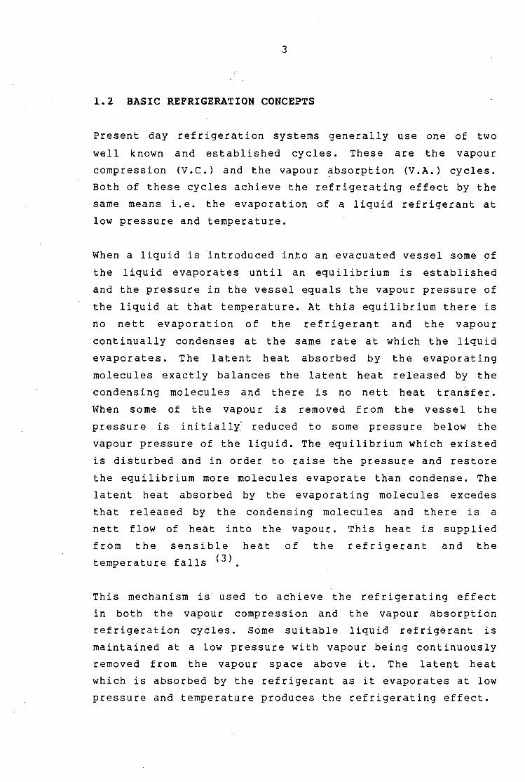
1.2 BASIC REFRIGERATION CONCEPTS
Present day refrigeration systems generally use one of two
well known and established cycles. These are the vapour
compression (V.C.) and the vapour ~bsorption (V.A.) cycles.
Both of these cycles achieve the refrigerating effect by the
same means i.e. the evaporation of a liquid refrigerant at
low pressure and temperature.
When a liquid is introduced into an evacuated vessel some of
the liquid evaporates until an equilibrium is established
and the pressure in the vessel equals the vapour pressure of
the liquid at that temperature. At this equilibrium there is
no nett evaporation of the refrigerant and the vapour
continually condenses at the same rate at which the liquid
evaporates. The latent heat absorbed by the evaporating
molecules exactly balances the latent heat released by the
condensing molecules and there is no nett heat transfer.
When some of the vapour is removed from the vessel the
pressure is initially reduced to some pressure below the
vapour pressure of the liquid. The equilibrium which existed
is disturbed and in order to raise the pressure and restore
the equilibrium more molecules evaporate than condense. The
latent heat absorbed by the evaporating molecules excedes
that released by the condensing molecules and there is a
nett flow of heat into the vapour. This heat is supplied
from the sensible heat of the refrigerant and the
temperature falls <3 J
This mechanism is used to achieve the refrigerating effect
in both the vapour compression and the vapour absorption
refrigeration cycles. Some suitable liquid refrigerant is
maintained at a low pressure with vapour being continuously
removed from the vapour space above it. The latent heat
which is absorbed by the refrigerant as it evaporates at low
pressure and temperature produces the refrigerating effect.

....---------------------·---------
4
In order for a small quantity of the refrigerant to be re
used in a closed cycle, the refrigerant evaporated to
produce the refrigerating effect must be returned to the
liquid state. To enable the condensation of the refrigerant
vapour, the pressure is raised. until the saturation
temperature is higher than the temperature of some
convenient heat sink. This enables the refrigerant vapour to
reject the latent heat of evaporation to the heat sink and
the vapour is able to condense to liquid. This heat
rejection is done in a condensex which is usually cooled by
water or air at ambient temperature.
The vapour compression and absorption cycles differ in the
method used to transport the refrigerant from the low
pressure side (evaporator) to the high pressure side
(condenser) of the system. The v.c. cycle uses a compressor
while the V.A. cycle employs a more complicated system in
which the refrigerant vapour is absorbed into a carrier
liquid on the low pressure side and released again on the
high pressure side.

5
1.3 THE VAPOUR COMPRESSION REFRIGERATION CYCLE
The vapour compression cycle is the simplest refrigeration
cycle and consists of an evaporator, a condenser, a
compressor and an expansion device. Figure 1.1 shows the
basic v.c. cycle.
The v. C. cycle can be represented on a pressure enthalpy
diagram as shown in Figure 1.2. Refering to this diagram,
saturated vapour at condition (1) is compressed (assumed
isentropically) to condition (2) which is superheated vapour
at the condenser pressure. This high temperature vapour
passes into the condenser where it is first de-superheated
and then condensed. The resulting saturated liquid at
condition ( 3) is then expanded with constant enthalpy to
condition (4). During the expansion flash gas (saturated
vapour) at condition (1) and saturated liquid at condition
(5) is formed with condition (4) being an _equilibrium
mixture of these two components. The saturated liquid at
condition (5) evaporates in the evaporator to form saturated
vapour at condition (1) and in the process absorbs its
latent heat of evaporation and produces a refrigerating
effect. This vapour along with the flash gas from the
expansion is then compresssed to the condenser pressure
thereby completing the cycle.
The coefficient of performance of the V .c. cycle has been
defined as :
Where
C.O.P = R.E. I w (l.l)
C.O.P = Coefficient of performance of the vapour
compression cycle.
R.E.
w = Refrigerating effect (kJ/kg).
=Compressor work (kJ/kg).

6
In most cases the refrigerating effect achieved is greater
than the work input ·to the cycle and the coefficient of
performance is greater than unity. From equation (1.1) it
can be seen that in order to increase the coefficient of
performance the compressor work must be decreased and or the
refrigerating effect increased.
A more detailed description of the single stage v.c. refrigerating cycle can be found in Appendix A as well as
references 3,4,S and 6.

7
FIG 1.1 SINGLE STAGE VAPOUR COMPRESSION REFRIGERATION CYCLE
Qcond
I Condenser
(2)
':ansion t Device I Compressor
High Pressure
------· ---- ----
w ! comp (1) (4)
Evaporator Low
FIG 1.2 SINGLE STAGE VAPOUR COMPRESSION CYCLE ON A PRESSURE -EN'E-IALPY DIAGRAM
Pressure (P)
p cond
p evap
Condenser outlet
Constant enthalpy
expan~ 92
Condenser inlet
• Is entropic compression
1 Compressor inlet
Pressure
h'"' I Evapor~for inlet
Enthalpy (h)
Refri
Effect Work
Heat re·ected in the
Condenser
8
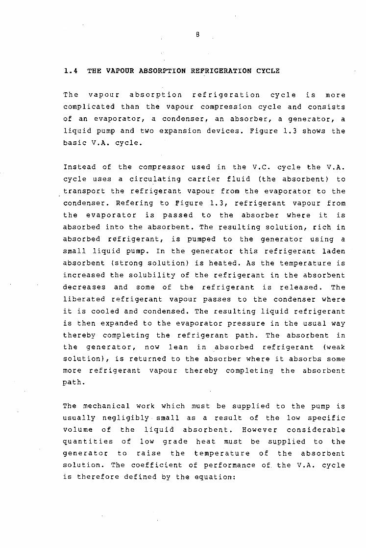
1.4 THE VAPOUR ABSORPTION REFRIGERATION CYCLE
The vapour absorption refrigeration cycle is more
complicated than the vapour compression cycle and consists
of an evaporator, a condenser, an absorber, a generator, a
liquid pump and two expansion devices. Figure 1.3 shows the
basic V.A. cycle.
Instead of the compressor used in the v. c. cycle the v. A.
cycle uses a c i rcu lat ing carrier flu id (the absorbent) to
transport the refrigerant vapour from the evaporator to the
condenser. Refering to Figure 1. 3, refrigerant vapour from
the evaporator is passed to the absorber where it is
absorbed into the absorbent. The resulting solution, rich in
absorbed refrigerant, is pumped to the generator using a
small 1 iqu id pump. In the generator th is refrigerant laden
absorbent (strong solution) is heated. As the temperature is
increased the solubility of the refrigerant in the absorbent
decreases and some of the refrigerant is released. The
liberated refrigerant vapour passes to the condenser where
it is cooled and condensed. The resulting liquid refrigerant
is then expanded to the evaporator pressure in the usual way
thereby completing the refrigerant path. The absorbent in
the generator, now lean in absorbed refrigerant (weak
solution), is returned to the absorber where it absorbs some
more refrigerant vapour thereby completing the absorbent
path.
The mechanical work which must be supplied to the pump is
usually negligibly. small as a result of the low specific
volume of the liquid absorbent. However considerable
quantities of low grade heat must be supplied to the
generator to raise the temperature of the absorbent
solution. The coefficient of performance of the v .A. cycle
is therefore defined by the equation:

9
C.O.P = R.E./Qgen ( 1. 2)
Where
C.O.P = Coefficient of performance of the vapour
absorption cycle.
R.E. = Refrigerating effect (kJ/kg).
Qgen = Heat supplied to the generator (kJ/kg).
The large generator heat input required for absorption
refrigeration systems usually results in a poor coefficient
of performance when compared directly to .compression
systems~ However it must be remembered that the electrical
energy usually used to power compression systems is
initially generated from heat. In the case of absorption
systems this heat can be used directly to heat the generator
whereas in compression systems the heat must first be
converted to mechanical power (usually via electrical power)
with large unavoidable losses. Thus if the performance of a
V • A • sys t em is to be co mp are d fa i r 1 y w i th that of a V . C .
system all generation and transmission losses from the
initial heat source to the point of use should be included.
The V.A. cycle is particularly suitable for use in
industries where waste heat is available for heating the
generator and or where the size of the system required would
result in undesirably large compressors if a v.c. cycle were
to be used.

10
The two main absorbent - refrigerant combinations which have
been commonly used with the absorption refrigeration cycle
are:
i) Lithium bromide and water with water as the refrigerant
and Lithium bromida as the absorbent.
ii) Ammonia and water with ammonia as the refrigerant and
water as the absorbent.
Although these absorbent refrigerant combinations are the
ones most often used in actual applications many other
possible combinations exist. Work performed in the 1950's by
research workers of the American company du Pont has
identified a number of solvents which readily absorb
fluoronated hydro - carbon refrigerants < 8 ). Some of these
substances have shown potential for use in absorption
refrigeration cycles. For example dimethyl ether - tetra
ethylene glycol (DME TEG) has been shown to be a
satisfactory absorbent for use with Refrigerant 22 <9 ,lO)
Further details on the absorption refrigeration cycle can be
found in Appendix A as well as references 4,5 and 6.

11
FIG 1.3 SIMPLE ABSORPTION REFRIGERATION SYSTEM
w pump
Pump
Generator
Strong (l) solution
Absorber
Weak solution
Refrigerant va our
(5) Refrigerant vapour
Condenser
(4) Saturated liquid refrigerant
Expansion Device
Saturated liquid +
flash gas
Evaporator
1 FIG 1.4 MULTIPLE EXPANSION VAPOUR.COMPRESSION REFRIGERATION CYCLE ON A
A PRESSURE - ENTHALPY DIAGRAM
Pressure (P)
dpl p
evap (4)
Refrigerating
Effect
Saturated vapour at this condition formed during the first expansion
gas from each expansion compressed isentropically to the condenser pressure
Enthalpy (h)

12
1.5 MULTIPLE EXPANSION VAPOUR COMPRESSION CYCLES
During the expansion of the saturated liquid refrigerant
from the condensing to the evaporating pressures, a portion
of the refrigerant "flashes" to vapour. Since this flash gas
has already undergone the liquid to vapour phase change
before it enters the evaporator, it cannot produce any
refrigerating effect in the evaporator. However in order to
maintain the closed cycle this flash gas has to be
compressed to the condensing pressure. and work must be
supplied to do this. This work, which is unavoidable, is
performed on a portion of the refrigerant that does not
produce any refrigerating effect and the result is a lower
coefficient of performance than would be achieved if there
was no flash gas formed during the expansion.
The expansion and compression of the single stage v.c. cycle
can in principle be replaced by a series of smaller
expansions and comptessions as shown in Figure 1.4. Refering
to this diagram, saturated liquid at the condensing
pressure, i.e. condition (3), is expanded through a small
pressure drop dp to a pressure of P cond - dp. During this
expansion some of the liquid flashes to vapour and a mixture
of saturated liquid and saturated vapour results. The vapour
is separated from the liquid and independantly compressed to
the condenser pressure. The remaining liquid, which is now
at a lower enthalpy than before the expansion, is expanded
through a further pressure drop of dp. The flash gas formed
during this expansion is again separated from the liquid and
compressed to the condenser pressure while the liquid is
expanded further. This process is repeated until the
pressure of the refrigerant becomes equal to the desired
evaporator pressure. The refrigerant is then evaporated in
the usual way to produce the refrigerating effect.
The result of this series of expansions and compressions is
that less of the refrigerant vapour has to be compressed
13
through the maximum system pressure difference i.e. Pcond -
Pevap· Only vapour which has undergone a phase change in the
evaporator would have to be compressed from the lowest to
the highest system pressure. Less compressor work would
therefore be requited for a given refrigerating effect. This
reduction in the compressor work would result in an improved
coefficient of performance.
Furthermore since the enthalpy of the refrigerant entering
the evaporator is reduced from what it would be with a
single expansion (see Figure 1.4), the refrigerating effect
is increased i.e. For the same refrigerant flow rate in the
evaporator more heat would be absorbed.
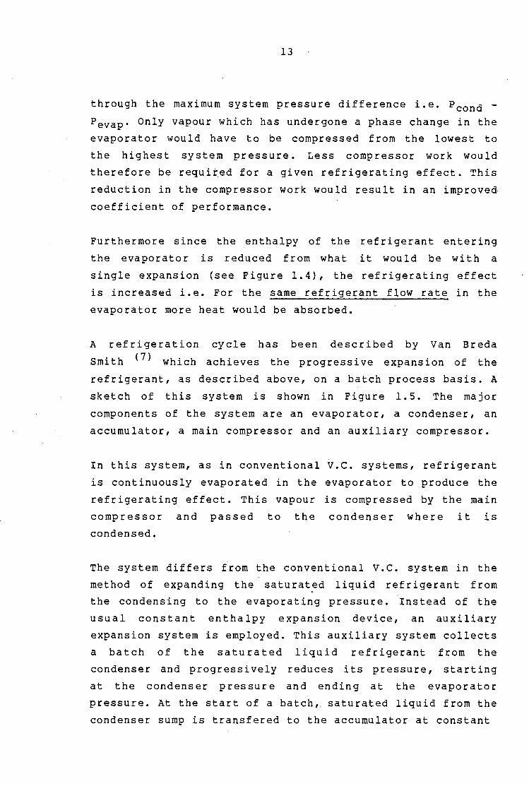
A ref ri gera ti on cycle has been described by Van Breda
Smith <7
> which achieves the progressive expansion of the
refrigerant, as described above, on a batch process basis. A
sketch of this system is shown in Figure 1.5. The major
components of the system are an evaporator, a condenser, an
accumulator, a main compressor and an auxiliary compressor.
In this system, as in conventional v.c. systems, refrigerant
is continuously evaporated in the evaporator to produce the
refrigerating effect. This vapour is compressed by the main
compressor and passed to the condenser where it is
condensed.
The system differs from the conventional v.c. system in the
method of expanding the saturated liquid refrigerant from
the condensing to the evaporating pressure. Instead of the
usual constant enthalpy expansion device, an auxiliary
expansion system is employed. This auxiliary system collects
a batch of the saturated liquid refrigerant from the
condenser and progressively reduces its pressure, starting
at the condenser pressure and ending at the evaporator
pressure. At the start of a batch, saturated liquid from the
condenser sump is transfered to the accumulator at constant

14
FIG 1.5 DIFFERENTIAL BATCH EXPANSION AND COMPRESSION REFRIGERATION SYSTEM
w main
Condenser
Main Compressor
Evaporator
(1)
Accumulator
w aux
Auxiliary Compressor

15
pressure. For this operation valve (1) is opened and valve
(2) is closed. Once the accumulator has been fully charged,
valve (1) is closed and the auxiliary compressor begins to
reduce the pressure of the refrigerant in the accumulator.
Flash gas is formed as each induction stroke of the
compressor causes a lowering of the pressure in the
accumulator. This flash gas is compressed by the auxiliary
compressor from the pressure ·at which it is formed to the
condenser pressure. Once the pressure in the accumulator
reaches the evaporator pressure, valve (2) is opened and the
refrigerant flows at constant pressure into the evaporator
where it is evaporated to produce the refrigerating effect.
When the accumulator has discharged all of the refrigerant,
valve (2) is closed and the expansion process is repeated on
another batch of refrigerant from the condenser.
The differential batch expansion system, as this system has
been called, is an effective batch process multiple
expansion and compression refrigeration cycle. Each stroke
of the auxiliary compressor causes a small reduction in the
pressure in the accumulator and this results in a sma 11
expansion of the refrigerant. The size and speed of the
auxiliary compressor determines the number of expansions
achieved and the compressor friction losses suffered. A
small volume high speed auxiliary compressor would result in
a large number of expansions but high compressor friction
losses while a large volume low speed auxiliary compressor
would result in a smaller number of expansions but lower
friction losses. Clearly the size and speed of the auxillary
compressor should be chosen so that the extra friction
losses in the auxiliary compressor do not outweigh any gain
in performance resulting from the multiple expansions.
Although the system effectively achieves a very large number
of expansions it is however a batch process system which is
generally less des i0
rable than a continuous process system
for industrial applications. From a practical point of view

16
the differential. batch expansion system might be improved
for an actual installation by the introduction of a second
accumulator operating in parallel to the existing one. This
would allow one accumulator to be charged or discharged
while the other was being decompressed. This would enable
the au x i 1 i a ry
switching to
compressor to operate continuously, merely
the other accumulator as it finished
decompressing the first.
The multiple expansion vapour compression cycle, as
represented in Figure 1.4, would require special
arrangements to effect the compression of the flash gas from
each expansion stage. Two possible options which could be
considered to compress the flash gas to the condenser
pressure are:
• i) To use several small auxiliary compressors where each
compressor is dedicated to one stage and designed to
operate between the stage pressure and the condenser
pressure. Such a system would suffer from a high
initial cost due to the large number of compressors
required. In addition, since the friction losses of
each compressor would be similar to those of the much
larger main compressor, it is probable that any gain in
performance due to multiple expansions would be lost to
increaied compressor friction.
ii) To use a single auxiliary compressor which had a single
discharge at the condenser pressure and which was
capable of compressing _vapour from many different
suet ion pressures corresponding to the pressures at
each expansion stage. Such a compressor would require
considerable development and thus this option cannot be
readily achieved in practice.
In view of the difficulties of compressing the flash gas
formed in a multiple expansion and compression cycle, a

.,
. \
17
refrigeration cycle ~as pr6~osed in which a small auxiliary
absorption. system · .. was combined with a multiple expansion
v.c. cycle. The'·absor:ptioz: part of the cycle would absorb
the flash gas from each expansion and retur·n it to the . • I
condenser using standar9 absorption techniques.·· The
" compressor would then be left to compress the bulk of the
refri9er~ant vapour, .i.e.: the vapour evaporated in the
eva·po:rator to. p'ro·du¢e ,a· re·frigerating effect, to the .i •(
- ' condense.r pressure. Figur~ l. 6 shows a simplified. flow I
diagram of the proposed mulptiple expansion - absorption '
refriger.ation cycle. W~th this cycle it was expected. that
the compres.sbr work:/perfor~ed per unit of refrigeration • ' • ,/ ~ 'It. '
would be' reduced si,nce1 it-. wbul'd no longer be compressing the . " ... .. "
flash gas as in a'normal'V.C. c'ycle. The absorption side of
the cycle would require littfe mecha~ic~l work with the main
energy input to. this":_part of. the cycle being heat. It was • 1 -
therefore anticipated that, if >this heat was: available as i •
waste energy which woulq otherwise be rejected to the )
environment and could thus. be( considered as '"free", savings
in high grade' enei'.gy would~ be .r;ealised with' the combined ' . "" ..
compressi-oq - absorption) ,sys~~m.,.un order~ to be able to use
a fluoronated hydro ~ carbon. refrigerant it was proposed to . . : I
use dimethyl ether ...: . .tetra. ethy1en.e glycol (DME - TEG) as
the absorbent. This' solvent, a~ previously mentioned, has ~ t • j
been shown ( 9 ' lO) to b~ a . satisfactory absorbent for use
with difluoro chluoro ·metha~e (.R22l as refrigerant. ,. ' . •. • l .,- "

19
CHAPTER 2
THEORETICAL ASPECTS OF MULTIPLE EXPANSION CYCLES
2.1 PERFORMANCE LOSS DUE TO FLASH GAS FORMATION
The formation of flash gas during the expansion of the
refrigerant in any refrigeration cycle leads to a lower
coefficient of performance for the cycle than would be
achieved if no flashing to vapour occured. This is because
the flash gas, which cannot produce any refrigerating
effect, still has to have work done on it to return it to
the condenser. This work is expended on a non productive
portion of the refrigerant and this reduces the performance.
Figure 2.1 shows a simple refrigeration cycle with a
constant enthalpy expansion on a P-h diagram. From energy
and mass balances on the refrigerant it can be shown that
the fraction of the refrigerant that flashes to vapour in
the expansion is given by the equation
x = (h2-h3)/(h4-h3) ( 2. 1)
Where
x = Vapour fraction.
h· l = Refrigerant enthalpy at cycle point i (kJ/kg).
i = Cycle point number as shown on Figure 2 .1.

20
The flash gas mass flow rate and the compressor work
required to recornpress the vapour to the original pressure
are given by the equations :
Where
rnf = x·rn1
W f = rnf . ( h 5 - h 4 )
( 2. 2)
( 2. 3)
rnf =Flash gas mass flow rate (kg/s).
m1 = Refrigeran~ mass flow rate at point 1 (kg/s).
Wf = Compressor work required to compress
the flash gas (kJ/s).
The flash gas takes up compressor capacity (in the case of a
V.C. cycle) and absorber/generator capacity (in the case of.
an absorption cycle) which could otherwise, if there was no
flash gas, be used for refrigerant vapour which had produced
a refrigerating effect. The refrigerating capacity of the
sytern is thus reduced by the existence of the flash gas.

21
FIG 2.1 SIMPLE VAPOUR COMPRESSION REFRIGERATION CYCLE ON A PRESSURE -
ENTHALPY DIAGRAM
Pressure (P)
Enthalpy (h)

22
2.2 THE MULTIPLE EXPANSION VAPOUR COMPRESSION CYCLE
The multiple expansion and compression cycle can be analysed
theoretically using a similar approach to that used foi the
single stage V. C. cycle. Figure 2. 2 shows the flow diagram
of the cycle with various points in the cycle numbered for
easy reference. The numbered points correspond with those in
Figure 2.3 which shows the same cycle represented on a P-h
diagram. The equations which describe the cycle are
presented below. Each item in the system has been considered
individually and the subscripts refer to the numbered points
shown in Figures 2.2 and 2.3.
For the first expansion :
Where
Xl = (h2-h3)/(h4-h3)
m4 = X1·m1
m3 = (l-x1>·m1 Wl = m4 · <h1a-h4 >
x1 = Vapour fraction for first stage.
( 2. 4)
( 2. 5)
( 2. 6)
( 2. 7)
hi= Refrigerant enthalpy at cycle point i (kJ/kg).
mi = Refrigerant mass flow rate at cycle
point i (kg/s).
W1 = Compressor work to compress the flash gas
from the first stage (kJ/kg).
Similar equations to these can be developed for each of the
expansion stages and enable the mass flow rates and
compressor work for every stage to be deternmined.
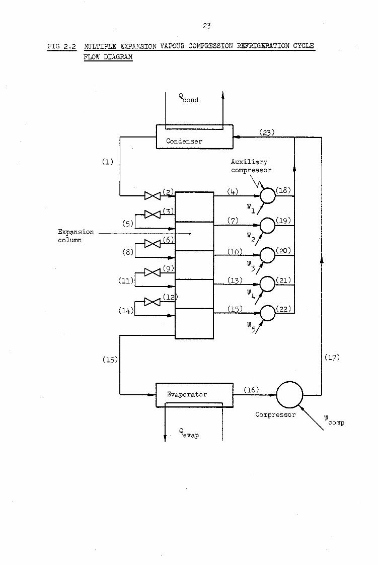
FIG 2.2 MULTIPLE EXPANSION VAPOUR COMPRESSION REFRIGERATION CYCLE FLOW DIAGRAM
Condenser
(1)
(23)
Auxiliary compressor
(4)
(5) '-------ti---...,.._J...f...L~..J Expansion --------1-column
(11) '----.....i
(15)
Evaporator
(18)
(19)
(20)
(21)
(22)
(17)
w comp

24
FIG 2.3 MULTIPLE EXPANSION VAPOUR COMPRESSION REFRIGERATION CYCLE ON A PRESSURE - ENTHALPY DIAGRAM
Pressure (P)
(19) (21)
(1) (18) (20) (22) .._ ____________ ......, _________ __ (3 )A--------~<4..;..;.)-¥
(6) "--_<2_) ____ ---'(....;_7)~
(9) ~-(....:...5_) _____ <_10_)~ (8) (13)
Enthalpy (h)

25
For the evaporator :
( 2. 8)
Where
Qevap = Heat absorbed in the evaporator (kJ/s).
Cpw = Specific heat capacity of water ( kJ /kg K) •
mwe = Mass flow rate of evaporator heating
water (kg/s).
dTwe = Evaporator heating water temperature
change (K)
For the compressor :
( 2. 9)
Where
Wcomp =Main compressor work (kJ/s).
For the system :
The coefficient of performance of the system can be defined
by the equation
C.O.P. = Oevap I Wtotal
= Oevap I [ Wcomp w. ] J (2.10)

26
Where
C.O.P. = Coefficient of performance of the multiple
expansion and compression cycle.
wj = Auxiliary compressbr work for the jth stage (kJ/s}.
From Figure 2.3 it can be seen
from the first stage to the
that to compress flash gas
condensing pressure would
require an ideal work input of (h 18 -h 4 ) kJ/kg. To compress
vapour from the last stage to the condensing pressure would
require a work input of (h22-h1s> kJ/kg. Less compressor
work is therefore required to compress flash gas from the
stage pressures than f rorn the lower evaporating pressure to
the condensing pressure. It can therefore be predicted that
the theoretical performance of the multiple expansion and
compression cycle would be better than that of a sing le
stage cycle.
Full details of a theoretical analysis of the cycle which
was performed using the above equations encoded into a
computer programme have been presented in appendix B.
/

27
2.3 THE MULTIPLE EXPANSION - ABSORPTION CYCLE
The multiple expansion abs or pt ion eye le can also be
theoretically analysed using methods similar to those used
for other refrigeration cycles. Figure 2.4 shows the cycle
with various points numbered for easy reference. ·The
equations for the system have been developed below u~ing
subscripts which refer to the numbered cycle points in
Figure 2.4. For simplicity each item in the system has been
considered individually.
For the expansion column :
The expansion process performed in the expansion column has
been shown on a p-h diagram for the refrigerant in Figure
2 . 5 • I n e a c h s t a g e s a t u r a t e d 1 i q u id i s expand ea w i th
constant enthalpy to a lower pressure. In the process flash
gas and saturated liquid (at a lower enthalpy) is formed.
Considering the first expansion the following equations can
be developed :
Where
Xl = (h2-h3)/(h4-h3)
m4 = X1·m1 m3 = (l-x1 ).m1
Xl = Vapour fraction at stage
h· l = Refrigerant enthalpy at
m· = Mass flow rate at cycle l
i = Cycle point as shown on
1.
(2.11)
(2.12)
(2.13)
cycle point i (kJ/kg).
point i (kg/s).
Figures 2.4 and 2. 5.
Similar equations can be developed for all the stages of the
expansion.

FIG
2.4
M
ULT
IPLE
EX
PAN
SioN
·-A
BSO
RPTI
ON
RE
FRIG
ERA
TIO
N C
YCL
E FL
OW
DIAG
RAM
(28)
(2
7)
Co
nd
ense
r ..
(1)
•' ....
(4)
(18)
....
. .:
-; ...
I•
, ~
i'
(3)
(7)
(19)
''•
(6)
(10
).
(20)
~.
(9)
(13)
(2
1)
(12)
(1
6)
(22)
(14
} ,'
~
,''
_., .
.,,. ~
·(1
7)
(15)
Ev
apo
rato
r (1
6)
. C
om
pre
sso
r
~; ( J
... ;
..
(26
)
Ab
sorb
er
(25
)
·~·
; ''I'-'
. ------"
(24)
Ab
sorb
ent
pum
p
(\)
CX>

29
FIG 2,5 EXPANSION PROCESS OF THE MULTIPLE EXPANSION - ABSORPTION CYCLE ON A PRESSURE - ENTHALPY DIAGRAM
Pressure (P)
(4)
(7) (10)
Enthalpy (h)

30
For the last expansion
X5 = (h14-h15)/(h15-h15)
m15 = (l-x5)·m12
m15 = X5·m12
(2.14)
(2.15)
(2.16)
Substituting for m12 etc in (2.15) and (2.16) gives
m15 = (l-x1Hl-x2Hl-x3Hl-x4)·(l-x5)·m1
m15 = x1·x2·x3·x4·x5·m1
For the evaporator :
(2.17)
(2.18)
The heat absorbed in the evaporator is given by the usual
equation
Where
(2.19)
Oevap =Heat absorbed in the evaporator (kJ/s).
mwe =Heating water mass flow rate (kg/s).
Cpw =Specific heat capacity of water (kJ/kg K).
dTwe = Evaporator heating water temperature
change (K).
For_the compressor :
The theoretical work input to the compressor is given by the
equation :
(2.20)

31
Where
Wcomp =Compressor work (kJ/s).
For the absorber :
The absorber can be analysed by considering mass and energy
balances on the vessel. Although. the absorber would not in
practice be insulated it has been assumed for simplicity
that all heat transfer is to the cooling water.
Overall mass balance gives
(2.21)
Energy balance gives
23
mwa. Cpw. dTwa = L mj. hj + m24. h24
j=l8
(2.22)
Refrigerant mass balance gives
Where
22
m24 · C24 = m23 · C23 +· L mj j=l8
(2.23)
mwa =Absorber cooling water flow rate (kg/s).
dTwa = Absorber cooling water temperature
change (K).
Cpw =Specific heat capacity of water (kJ/kg K).
Ci = Refrigerant concentration in the
absorbent at cycle point i (%by mass).

32
For the generator :
The generator can similarly be analysed by considering mass
and energy balances.
Overall mass balance gives
(2.24)
Energy balance (assuming perfect insulation)gives
Refrigerant mass balance gives
Where
(2.26)
Ogen= Heat supplied to the generator CkJ/s).
Ci = Concentration of refrigerant in the
absorbent at cycle point i (kg/kg).
For the pump
The work input to the pump is given by the equation
(2.27)
Where
Wpump =Work input to absorbent pump (kJ/s).
(2.25)

33
For the condenser :
Assuming the condenser to be perfectly insulated the
following equations can be developed :
(2.28)
Assuming that no heat losses occur in the pipework
connecting the condenser, generator and compressor an energy
balance of the mixing of the two refrigerant flows gives :
(2.29)
Also
(2.30)
For the system :
Depending on the. particular application of the cycle, the
circumstances relating to the supply of "waste" energy and
what is considered to be the energy "inpu't" to the system
the coefficient of performance could be defined in a number
of ways. For the purposes of this theoretical analysis all
energy inputs to the cycle are considered and the
coefficient of performance is then defined as :
Where
C.O.P. = Oevap I [Wcomp + Wpump + Ogenl (2.31)
C.O.P. = Coefficient of performance of multiple
expansion - absorption cycle.

34
The enthalpies required for these calculations are obtained
from the Pressure - enthalpy diagram for the refrigerant and
from the concentration enthalpy diagram for the
refrigerant absorbent combination. The mass flow rates
required are obtained from the design specifications of the
required refrigerating capacity and the relevant energy and
mass balance equations.
Since concentration - enthalpy diagrams for R22 and dimethyl
ether - tetra ethylene glycol could not be obtained it was
not possible to perform these calculations and thereby
determine a theoretical COP for the cycle. An experimental
approach was therefore followed to determine the performance
of the cycle.

35
CHAPTER 3
EXPERIMENTAL APPARATUS
3.1 GENERAL DESCRIPTION
The multiple expansion - absorption experimental apparatus
consisted of an evaporator, condenser, expansion column,
compressor, absorber, generator, heat exchanger and pump
unit arranged as shown in the system flow diagram of Figure
3. l.
Saturated liquid refrigerant from the condenser was passed
to the expansion column where it was expanded in five stages
to the evaporating pressure. The low presssure saturated
liquid from the last stage of the expansion column passed
into the bottom of the evaporator where it was evaporated to
produce the refrigerating effect. Refrigerant vapour was
extracted from the top of the evaporator and compressed to
the condensing pressure by the compressor.
Flash gas formed with each expansion was separated from the
liquid in the expansion chamber and passed via a pressure
reducing valve to the absorber where it was absorbed.
Refrigerant laden absorbent (strong solution) was pumped
from the absorber to the generator where it was heated by an
electric element. The refrigerant vapour released from the
strong solution in the generator was passed to the condenser
where it was condensed along with the refrigerant vapour
from the compressor. A non return valve allowed vapour to
"blow off" from the generator as the pressure there became
higher than the pressure in the condenser while preventing

36
the flow of vapour from the compressor into the generator.
Refrigerant depleted absorbent {weak solution) flowed f rem
the generator back to the absorber through a regenerative
heat exchanger where it partially cooled in the process of
pre heating the cold absorbent being pumped to the
generator . Cooling coils in the top section of the absorber
cooled to nearly ambient temperature the warm absorbent
returning to the absorber so enabling it to re-absorb
refrigerant vapour. A throttling valve was used to maintain
the pressure difference between the generator and the
absorber.
Plate 3.1 shows a photograph of the experimental apparatus
which was constructed on a tubular steel framework with
chipboard back and centre panels. The apparatus was arranged
with the absorption equipment i.e. generator, absorber and
pump u n it a 11 1 o cat e d on one s id e of a centre dividing
panel. The remaining i terns were located on the other side
and the rig was therefore roughly divided into an absorption
and a compression side. The various vessels in the system
were mounted onto the back and centre panels with
appropriate brackets while the compressor and pump unit were
mounted onto steel base plates across the bottom of the
frame. Detailed descriptions and constructional details of
each piece of equipment have been given under separate
headings below.

FIG
3 .1
M
UL
TIP
LE
E
XPA
NSI
ON
-
AB
SOR
PTIO
N
SYST
EM
:F
LOW
D
IAG
RA
M
Co
oli
ng
w
ater
Ex
pan
sio
n
colu
mn
by
-pas
s
Co
nd
ense
r
Ex
pan
sio
n
colu
mn
....
. . .
, ...
....
....
.
. '
..
..
....
. .
.
Hea
tin
g w
ater
Co
mp
ress
or
Gen
era
tor
Co
oli
ng
w
ate
r A
ir
Ble
ed
Ab
sorb
er
Dra
in
Dra
in
Lev
el
co
ntr
oll
er
I I • S
ign
al
to
pum
p m
oto
r
Hea
t ex
chan
ger
LEG
END
---[
:>t-
--N
on
retu
rn v
alv
e
-t>
<J-
Man
ual
valv
e
@--
Pre
ssu
re in
dic
ato
r
&
Tem
per
atu
re in
d.
~ L
evel
sw
itch

1:1.ash -~o th
The:'!ll
Ic-=
PLATE 3.1 GENERAL VIEW OF THE EXPERIMENTAL APPARATUS
Non return valve Condenser
ol
39
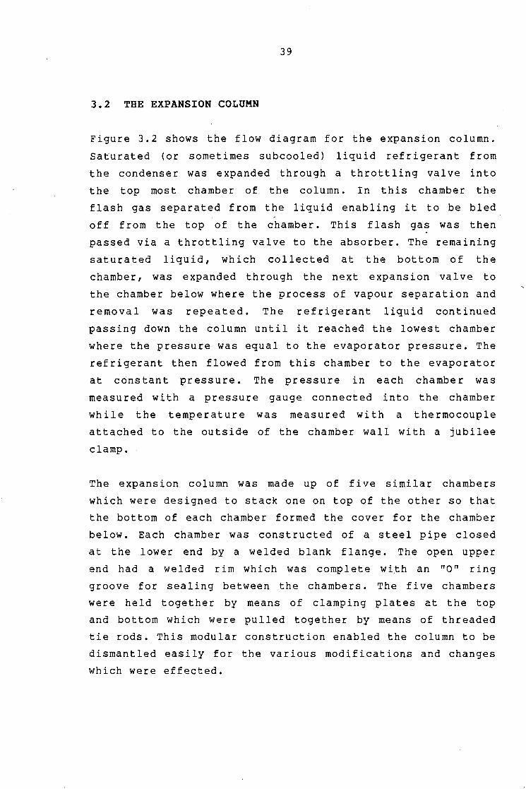
3.2 THE EXPANSION COLUMN
Figure 3.2 shows the flow diagram for the expansion column.
Saturated (or sometimes subcooled) liquid refrigerant from
the condenser was expanded through a throttling valve into
the top most chamber of the column. In this chamber the
flash gas separated from the liquid enabling it to be bled ,
off from the top of the chamber. This flash gas was then
passed via a throttling valve to the absorber. The remaining
saturated liquid, which collected at the bottom of the
chamber, was expanded through the next expansion valve to
the chamber below where the process of vapour separation and
removal was repeated. The refrigerant liquid continued
passing down the column until it reached the lowest chamber
where the pressure was equal to the evaporator pressure. The
refrigerant then flowed from this chamber to the evaporator
at constant pressure. The pressure in each chamber was
measured with a pressure gauge connected into the chamber
while the temperature was measured with a thermocouple
attached to the outside of the chamber wall with a jubilee
clamp.
The expansion column was made up of five similar chambers
which were designed to stack one on top of the other so that
the bottom of each chamber formed the cover for the chamber
below. Each chamber was constructed of a steel pipe closed
at the lower end by a welded blank flange. The open upper
end had a welded rim which was complete wi.th an "O" ring
groove for sealing between the chambers. The five chambers
were held together by means of clamping plates at the top
and bottom which were pulled together by means of threaded
tie rods. This modular construction enabled the column to be
dismantled easily for the various modifications and changes
which were effected.

40·
Each chamber was manufactured complete with the expansion
valve, flash gas throttling valve, pressure gauge connection
and fluid passages in the bottom flange which was made thick
enough for this purpose. All the fittings and valves were
silver soldered directly into the flanges to minimize the
number of joints where leaks could occur.
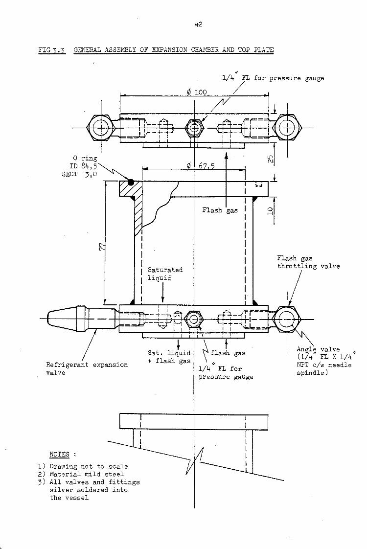
Figure 3. 3 shows a general assembly of the top most
expansion chamber and its cover plate which was only
required for the top chamber. All of the other chambers were
similar with the exception of the bottom chamber which did
not have those features in the bottom flange which were
required for the chamber below.
Plate 3. 2 shows a photograph of the assembled five stage
expansion column with the insulation removed. Clearly
visible in the photograph are the expansion valves, flash
gas throttling valves, clamping plates, tie rods and
pressure gauges.

FIG ) .2 EXPANSION COLUMN FLOW DIAGRAM
Saturated liquid from condenser
Expansion . . . . .. . . ... . . . . . .
.. . .. : . ~. . . . .. .
41
Top most Expansion chamber
Satc1rated vapour ( flash gas ) to the absorber
vapour
Throttling valve
Saturated liquid
I
I I /
I
/ I
.. .. . .. . .. . ------1,· . . · :· .. . · ...
Saturated liquid to the evaporator
I I I
Bottom most expansion chamber.
E)- Pressure indicator
8- Temperature indicator
~ Throttling v-al-.re
42
FIG 3 .3 GENERAL ASSEMBLY OF EXPANSION CHAMBER AND TOP PLATE
II
1/4 FL for pressure gauge
¢ 100 /
0 ring ID 84,5
SECT 3,0
Saturated
liqld
_ I I -~--+-
Refrigerant expansion valve
NOTES :
1) Drawing not to scale 2) Material mild steel 3) All valves and fittings
silver soldered into the vessel
+ Sat. liquid + flash gas I
I Flash gas I
I I I I I I I I I 1·
~flasl gas //
1/4 FL for pressure gauge
Flash gas throttling valve
Angle valve II .4•
(1/4 FL X 1/4 NPT c/w needle spindle)

43
PLATE 3 .2 ASSEMBLED EXPANSION COLUMN WITH THE INSULATION REMOVED
&.turated feed from
Expansion
late
Topmo t /expan ion
chamb r
nas gas thro ling valv
r d
couple
ing

44
3.3 THE GENERATOR
Figure 3.4 shows the flow diagram of the generator which was
in essence a cylindrical steel vessel equiped with an
electric heating element in the bot tom. Strong absorbent
solution in the vessel was heated by the element and the
refrigerant driven off. The released vapour collected in the
top of the vessel from where it passed out of the generator
to the condenser. The weak solution remaining, being of
higher density than the strong solution, migrated due to
gravity to the bottom of the generator from where it flowed
out of the generator to the absorber. The temperature in the
generator was controlled by a thermostat which operated the
heating element. The liquid level was maintained between set
levels by a simple level controller which started and
stopped the absorbent pump when high and low level switches
in the vessel were activated. A pressure switch which
switched off the pump and the heating element at the maximum
safe generator pressure was fitted to the vessel to provide
over pressure protection.
Figure 3.5 shows a cross sectioned sketch of the generator
vessel which was constructed from a steel pipe (int. dia.
lOOmm and length 250mm) which was closed at the top and
flanged at the bottom. A spiral heating element (220 v, 1
kW), a drain valve and a liquid outlet connection were
fitted into the blank flange which formed the bottom of the
vessel. A sight glass which indicated the liquid level in
the vessel was fitted to the side of the vessel and a level
control unit was inserted into the vessel through the top.
The level control unit consisted of two copper tubes which
were sealed at the lower end and at the fixing flange and
which projected down into the vessel. A copper float with an
open top was constrained to slide up and down the outside of
the tubes. Reed switches which were embedded in "Tufnol"
rods inside the copper tubes were arranged so that they

45
could be activated by a small magnet affixed to the float.
Provision was made to raise and lower the rods containing
the reed switches which enabled the set high and low liquid
levels to be adjusted easily. The reed switches were
connected to external circuitry which switched the pump on
when the low level switch was activated and off when the
high level switch was activated by the magnet in the float.
A stilling tube was fitted around the level control unit to
provide a calm environment for the float and to prevent any
splashes which occured from entering and sinking the float.
Three connections for a pressure gauge, liquid inlet and
vapour outlet were made into the top of the vessel. The
liquid inlet was fitted with a down pipe, which extended to
below the minimum liquid level in the vessel. This minimised
the splashing caused by the liquid being pumped into the
vessel. A thermowell to accomodate the thermostat sensor
bu lb and a connect ion for the pressure switch were al so
provided in the top of the vessel.
Plate 3. 3 shows a photograph of the generator with the
insulation removed. Clearly visible in the photograph is the
absorbent inlet, vapour outlet, pressure switch, thermostat,
sight glass, drain and absorbent qutlet.

FIG 3.4 GENERATOR FLOW DIAGRAM
Refrigerant vapour to condenser
Refrigerant vapour
Thermostat
I I t
Signal to heating element
... . -
-we~K. ·sol.n. ·
\ Heating element
Absorbent (weak soln) to the absorber
46
Drain
& e-& @-0-
-£><J--
Absorbent (strong soln) from the absorber
Level controller
I ,_ Signal to pump
motor
Absorbent
LEGEND
Pressure indicator
Pressure switch
Temperature indicator
Temperature sensor
Level switch
Manual valve

1+7
FIG 3. 5 SECTION THROUGH THE GENERATOR
Copper tube for ·i,he reed switches
t ,, 0 Ring
Il) 2 1/8 // \ SECT 1/8 °
/ Top flange for sight glass
R C\J
z 102
. I Absorbent outlet
(1/4/'FL)
Level control unit
z 160
Absorbent inlet (l/4
11FL)
tube
for
~eating element ( 220 V, 1 _kW) .
""
•o· Ring ID 124,5 SECT 3,0
Drain c/w Angle valve (.1/4"FL X l/4QNPT)

48
PLATE .3 .3 GENERATOR WITH THE INSULATION REMOVED
- condenser valve
3i gh t glass
Pressure gauge
at

49
3.4 THE ABSORBER
Figure 3.6
absorbent
absorbed
shows the flow diagram of the absorber. Warm
( dimethy 1 ether - tet raethylene glycol) lean in
refrigerant (difluoro chluoro methane) was
introduced through a pressure reducing valve into the top of
the absorber. This weak solution was distributed over the
whole area of the vessel by a perforated distribution plate
and then allowed to cascade over the cooling coils located
in the upper section of the vessel. Cool weak absorbent
passed off the bottom of the coils and collected in the
reservoir at the bot tom of the vessel where refrigerant
vapour from the expansion column was passed through. In
order to improve the absorption rate, which depended on the
contact surface area between the fluids, the refrigerant
vapour entering the absorber was passed through a sintered
glass disc which broke the vapour stream into a large number
of fine bubbles. This effectively increased the surface area
of the vapour many fold and the absorption rate was improved
as a result. Any of the vapour which was not absorbed during
its passage through the absorbent reservoir rose into the
upper section of the absorber which contained the cooling
coils. In this section it became exposed to a large surface
area of absorbent covering the cooling coils which enabled
further absorption to occur. Non condensable gasses such as
air which entered the absorber and which were not absorbed,
collected at the top of the absorber from where they were
purged from the system using the air bleed valve. Absorbent
rich in absorbed refrigerant (strong solution) was extracted
out of the absorbent reservoir. Since the strong solution
was of lower density than the weak solution it would tend to
be located at the top of the liquid in the reservoir. To
account for this the absorbent was extracted from the upper
half of the liquid in the reservoir by means of an extension
piece fitted to the absorbent outlet port. This extension
piece was made conical in shape with a larger area at the
top. This reduced the velocity of the absorbent entering the

50
outlet and minimised the chance of unabsorbed bubbles of
refrigerant vapour being sucked down the outlet and into the
pump.
Figure 3. 7 shows a cross section of the absorber vessel
which consisted of an upper section containing the cooling
coils and a lower section which formed the absorbent
reservoir. The upper section of the absorber was constructed
from a steel pipe which was flanged at the ends and closed
at the· top with a blank flange. A cooling coil was
constructed from 16 metres of 3/16 inch copper tube wrapped
in 3 layers (spaced 2,5 mm) around a central 3/4 inch copper
pipe which was attached to the top flange. The ends of the
coil were passed through the flange and connections for the
water supply pipes were provided. Also included into the top
flange was an air bleed port complete with a shut off valve
and an absorbent inlet port complete with a pressure
reducing valve.
The lower reservoir section of the absorber was constructed
from a thick walled mild steel cylinder which was fitted
with two portholes enabling the observation of the vapour
inlets at the bottom of the absorber. This reservoir section
was clamped between the bottom flange and the lower flange
of the upper section where it was sealed with "O" rings.
This section was used as a replacement piece for a glass
cylinder which was originally used for the lower section but
which was unable to withstand the pressure involved.
The bottom flange made provision for five vapour inlets, an
absorbent outlet and a drain. The absorbent outlet complete
with the screwed extension piece and a valve was located
centrally in the reservoir. The five vapour inlet ports were
then evenly spaced around it. A retaining plate which
contained five sintered glass discs (dia. 20mm, porosity 4)
was secured in position over the inlet ports such that each
port was covered by a disc. The bottom flange was also

51
fitted with a drain.
Plate
visible
3.4 shows a photograph of the absorber. Clearly
in the picture are the viewing portholes, vapour
pressure gauge, air bleed valve and absorbent inlets,
outlet.

FIG 3.6 ABSORBER FLOW DIAGRAM
Absorbent ( wea.1-c solution) from the generator
Cooling water in
7 //
Distribution plate
Viewing porthole
Refrigerant vapour from expansion ~~--f
column
52
Cooling water .-----out
Air and other 1---ti• non absorbed
gasses
/Cooling coils
Extension piece
~
Absorbent reservoir
Drain
Absorbent (strong solution) to the absorber

53 FIG 3.7 SECTION THROUGH THE ABSORBER
Absorbent inlet
Angle valve (1/4' FL X l/4q NPT)
Cooling water inlet
"o"R· - ing ID 94,5 1
s~/I Cooling water coil
1
(16m of 3/16 '' Cu tube wrapped in 3 layers around a central core)
Sight glass
,, Vapour inlet (1/4 FL)
I I
Cooling water outlet
Air bleed valve
" Perforated spreader plate
/Y tv
Absorbent outlet
IJ"'\ ...:::t ...:::t

PLATE 3,4 THE ABSORBER
Heat
P.efrigerant pipes
54
Pressure au e
\nl
ck et
e

55
3.5 THE EVAPORATOR AND CONDENSER
The evaporator was of shell and tube design with the
refrigerant on the shell side and the heating water on the
tube side. The vessel was constructed of a copper cylinder
(approximately 300mm long and 80mm diameter) with a single U
tube coi 1 which passed through the lower end plate. The
evaporator vessel was orientated vertically with the
refrigerant liquid inlet at the bottom and the vapour outlet
at the top. The evaporator was positioned relative to the
expansion column so that it operated approximatly half full
of liquid refrigerant which then evaporated from the surface
to produce the refrigerating effect. Heat was suppiied to
the evaporator by passing water at ambient temperature
through the internal coi 1. Thermocouples attached to the
water inlet and out let recorded the temperatures of the
water entering and leaving the evaporator. The heating water
mass flow rate was determined by filling a container for a
measured time and then weighing the contents.
The condenser was similarly of shell and tube design and
like the evaporator the refrigerant was on the shell side
and the cooling water on the tube side. The vessel was
constructed of a copper cylinder approximately 450mm long
and 60mm diameter. The condenser was orientated horizontally
with the vapour inlet uppermost and the liquid outlet at the
bottom on the opposite end of the vessel to the inlet. Heat
was removed from the condenser by water at ambient
temperature which was passed through the cooling coils.
Thermocouples attached to· the water inlet and outlet were
used to measure the temperature of the water entering and
leaving the condenser. The water flow rate was measured as
for the evaporator.

56
3.6 THE PUMP UNIT
The pump unit consisted of a modified positive displacement
hydraulic pump driven at reduced speed by a quarter
horsepower electric motor. A vee belt drive was used to
transmit the power and reduce the speed. The unit was
constructed onto a steel base plate which was placed across
the bottom of the frame and was complete with a charging
reservoir, 3 way charging valve and strainer.
Modifications which were made to the pump to make it
suitable for use with the chemically aggressive absorbent
included
i) The replacement of the original piston and cup seal
which were not resistant to the absorbent with a PTFE
piston. The replacement piston was also redesigned to
reduce the clearance volume and thus reduce the loss of
pumping capacity which occured because of dissolved
vapour being released from the solution.
ii) The halving of the pump capacity by adapting the pump
so that only one of the two pistons was in operation.
iii) The replacement of the steel valve discs with nylon
discs which were found to provide better valve
operation at the low speed at which the pump was used.
iv) The replacement of the original plastic valve spring
retainers which were not resistant to the absorbent
with similar ones manufactured from brass

57
3.7 THE COMPRESSOR UNIT
The compressor unit was of standard purchase and consisted
of a two cylinder Bitzer Type "O" refrigeration compressor
be 1 t driven by a half ho rs epowe r electric motor. The
compressor was complete with 3 way charging and evacuating
valves on the inlet and outlet ports. An oil separator was
fitted to the compressor discharge which removed compressor
oil entrained in the refrigerant vapour and returned it to
the crankcase. This was necessary to minimise oil
contamination in·the rest of the system and to ensure that
the crankcase oil level was maintained.
The electric motor was mounted on trunions and equiped with
a torque arm and balance weight which enabled the mechanical
power produced by the motor to be measured.
3.8 INSTRUMENTATION AND DATA MEASUREMENT METHODS
System temperatures at the locations shown in Figure 3.1 and
listed in appendix C were measured using Nickel - Chromium /
Nickel - Aluminium thermocouples. A multi - selector switch
was used to connect the thermocouples to a digital voltmeter
which was used to measure the emf. An ice bath was provided
for the reference junction so that the temperatures were
measured relative to zero degrees celcius.
The system pressures were measured using bourdon tube
pressure gauges of standard purchase located as shown on the
flow diagram of Figure 3.1.
The electric energy consumed by the pump motor, compressor
motor and generator heating element was measured using ' standard domestic kilowatthour {kwh) meters. Because the
heater and the absorbent pump operated intermittently
readings of. the instantaneous power drawn by these i terns

58
were meaningless. Therefore the total energy consumed was
measured for a known period of time and the average power
consumption calculated. Each of the above items were fitted
with a kwh meter from which readings were taken before and
after a measured time period. These readings were then
subtracted to determine the number of units of electricity
consumed during the period. Division of the energy consumed
by the time gave the average power consumption. To allow for
short term power fluctuations the test runs were conducted
over a period of one hour. Although the instantaneous
compressor power was nominally equal to the average power
(due to its continuous steady operation) the above procedure
was never the less used for the compressor as it eliminated
the effects of short term power fluctuations.
The compressor mechanical power was determined from the
motor torque and speed which were measured using the motor
torque arm and a hand held tachometer respectively. The pump
mechanical power was not measured because the short
intermittent periods for which it operated made it
impossible to balance the pump motor torque arm. In any
event the pump power was negligably small so its measurement
was not critical.
The evaporator, condenser and absorber water flow rates were
determined using a container, scale and stop watch. To
measure the flow rate the container was filled with the
water for a known time. The contents of the container were
then weighed and the. flow rate calculated by dividing the
mass of water collected by the collection time.

59
3.9 EXPERIMENTAL METHODOLOGY
The experimental apparatus was constructed such that it
could be operated both as a multiple expansion - absorption
cycle and as a single expansion and compression cycle. To
enable the two cycles to be compared easily the apparatus
was first run in multiple expansion - absorption mode and
then in single expansion mode between the same evaporating
and condensing pressures.
In multiple expansion - absorption mode the apparatus was
started and the expansion and flash gas throttling valves
adjusted until suitable expansion pressures were achieved. A
period of about one hour was then allowed for the apparatus
to stabilise. Once steady state was achieved a set of
readings was obtained from the kwh meters. The apparatus was
then allowed to operate for one hour at constant conditions
during which time the cooling and heating water flow rates
were determined as described in section 3.8. At the end of
the test period the kwh meter readings and the time were
again recorded. The system temperatures were then recorded
using the multi selector switch to select each
thermocouple location in turn. Finally the system pressures
were recorded from the pressure gauges. The apparatus was
then changed to single expansion mode.
In sing le expansion mode the expansion valve (manually
operated needle valve) and condenser cooling water flow rate
were adjusted until the evaporating and condensing pressures
were the same as those used for multiple expansion
operation. The system was then allowed to stabalise for
about one hour. Once steady state was achieved a set of
readings was obtained by recording the compressor kwh meter
reading and the time. The apparatus was then allowed to
operate at constant conditions for about half an hour during
which time the evaporator and condenser water flow rates

60
were measured. At the end of the time period the kwh meter
reading and the time were again recorded. The sytem
temperatures and pressures were th en recorded as before
concluding the test.

61
CHAPTER 4
4.1 RESULTS
TABLE 4.1 SUMMARY OF THE RESULTS OF A THEORETICAL ANALYSIS
OF THE PERFORMANCE OF A MULTIPLE EXPANSION VAPOUR
COMPRESSION REFRIGERATION CYCLE
THEORETICAL
CYCLE TYPE COP
Carnot 5,84
Single Stage v.c. 4.60
Two Stage V.C. 4,83
with Intercooling
Multiple Exp & Comp 5,20
(5 Stages)
Multiple Exp & Comp 5,33
(50 Stages)
Multiple Exp & Comp 5,34
(100 Stages)
Refrigerant -= R22
Condensing Temp = 35 °c Evaporating Temp = -10 °c
IMPROVEMENT IMPROVEMENT OVER
OVER SINGLE TWO STAGE INTER -
STAGE CYCLE COOLED CYCLE
( % ) ( % )
--- ---
--- ---
5,0 ---
13,0 7,6
16,0 10,5
16,1 10,6
Condensing Press = 13,l bar
Evaporating Press = 3,5 bar

62
FIG 4.1 BAR CHART OF THFDRETICAL COEFFICIENTS OF PERFORMANCE FOR VARIOUS REFRIGERATION CYCLES
eore ica . . Th t· 1 C 0 P
Carnot 5,84
Multiple expansion v.c. - 100 stages 5,34
Multiple expansion v.c. - 50 stages 5,33
Multiple expansion V.C. - 5 stages 5,20
2 Stage V.C. with intercooling 4,83
Single stage V.C. 4,60
FIG 4.2 BAR CHART SHOWING THEORETICAL IMPROVEMENTS IN PERFORMANCE CZ) OBTAINABLE WITH MULTIPLE EXPANSION V.C. CYCLES
2 Stage V.C. with intercooling
>::: 0
·r-1 co § p. :x; • (j) 0
(j) •
.-I > p.
·r-1 +' .-I
~
5 stages
50 stages
100 stages
......
P' 7 Z/J
, ... ···.· .:·1 .· ....... .
.......
Improvement above single stage V.C. cycle (%)
Improvement above 2 stage cycle with intercooling (%)
13,0 % ' ' \
16,0 %
16,1 %

63
TABLE 4.2 SUMMARY OF EXPERIMENTAL RESULTS OBTAINED WITH THE
MULTIPLE EXPANSION - ABSORPTION APPARATUS
DATA SET NO. 1 2 3
DATA SHEET NO. 2A 3A 4A
Evaporating Temp (deg C) -15,31 -18,77 -19,51
M Condensing Temp (deg C) 21,32 20,39 21,32
u Generator Temp (deg C) 99,51 117,04 117,78
L Temp of Exp Stage 1 (deg C) 14,81 14,57 15,56
Stage 2 11,85 9,38 9,14
E Stage 3 2,22 0,00 0,99
x Stage 4 - 7,65 -10,86 - 7,90
p Temp of Exp Stage 5 (deg C) -17,78 -18,27 -18,27
Refrigerating Effect (W) 238,17 255,06 208,46
A Comp Mech Power (W) 194,26 191,20 189,44
N Comp Elec Power (W) 302,00 319,00 317,00
D Ave Heater Power (W) 77,00 85,00 88,00
Ave Pump Power (W) 12,00 12,00 10,00
A COP (comp elec + heater + pump elec) 0,609 0,613 0,502
B COP (comp me ch + heater + pump elec) 0,841 0,885 0,725
s COP (comp me ch + pump elec) 1,155 1,255 1,045
COP (comp elec + pump elec) 0,759 0,771 0,638
DATA SHEET NO. '2B 3B 4B
0 Evaporating Temp (deg C) -15,31 -18,77 -19,75
N Condensing Temp (deg C) 21,32 21,11 21,32
E Refrigerating Effect (W) 122,81 217,17 194,05
Comp Mech Power (W) 189,99 194,39 189,44
E Comp Elec Power (W) 310,00 317,33 296,00
x COP (comp elec) 0,396 0,684 0,656 p COP (comp mech) 0,646 1,117 1,024
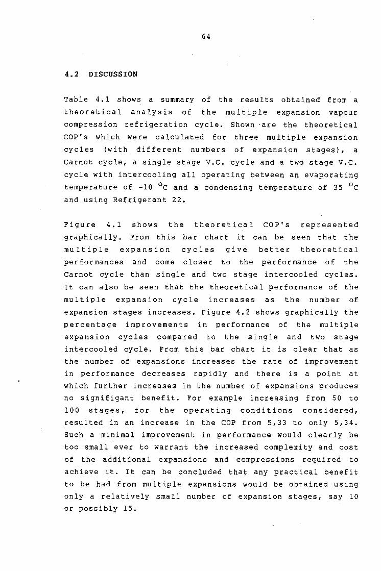
64
4.2 DISCUSSION
Table 4 .1 shows a summary of the results obtained from a
t h e o r e t i c a 1 a n a 1 y s i s o f t h e mu 1 t i p 1 e exp ans ion v a po u r
compression refrigeration cycle. Shown ·are the theoretical
COP' s which were calculated for three multiple expansion
cycles (with different numbers of expansion stages), a
Carnot cycle, a single stage v.c. cycle and a two stage V.C.
cycle with intercooling all operating between an evaporating
temperature of -10 °c and a condensing temperature of 35 °c and using Refrigerant 22.
Figure 4.1 shows the theoretical COP's represented
graphically. From this bar chart it can be seen that the
multiple expansion cycles give better theoretical
performances and come closer to the performance of the
Carnot cycle than single and two stage intercooled cycles.
It can also be seen that the theoretical performance of the
multiple expansion cycle increases as the number of
expansion stages increases. Figure 4.2 shows graphically the
percentage improvements in performance of the multiple
expansion cycles compared to the single and two stage
intercooled cycle. From this bar chart it is clear that as
the number of expansions increases the rate of improvement
in performance decreases rapidly and there is a point at
which further increases in the number of expansions produces
no signifigant benefit. For example increasing from 50 to
100 stages, for the operating conditions considered,
resulted in an increase in the COP from 5,33 to only 5,34.
Such a minimal improvement in performance would clearly be
too small ever to warrant the increased complexity and cost
of the additional expansions and compressions required to
achieve it. It can be concluded that any practical benefit
to be had from multiple expansions would be obtained using
only a relatively small number of expansion stages, say 10
or possibly 15.

65
The theoretical coefficients of performance were calculated
assuming isentropic compressions of the refrigerant and did
not allow for compressor friction losses. Thus the COP' s
which were calculated do not account for the increased
friction losses which would occur in the extra compressors
required for the multiple expansion vapour compression
cycles. It is probable that using many small auxiliary
compressors to compress the flash gas from each expansion
would not in practice result in an improved performance as
each of the compressors would suffer from disproportionately
high friction losses compared to the useful work performed.
In other words the additional friction losses in all of the
extra compressors would probably be greater than the work
saved by having multiple expansions. Use of a single
auxillary flash gas compressor capable of compressing gas
from various inlet pressures to a single dischar9e pressure
would limit the extra compressor friction losses suffered by
the system. However such a compressor is not available and
would require considerable development if the concept was
even possible. The most promising possibility for the
compression of the flash gas in a multiple expansion vapour
compression cycle would be the use of vapour jet ejectors.
An ejector would be required for each stage and would
operate off the main compressor discharge which would thus
be di vi de d into a number of paths cor resp on ding to the
number of stages. Since ejectors would be cheap and
essentially friction free their use would overcome the
problems of increased cost and friction losses resulting
from the use of additional compressors for the flash gas.
The use of ejectors in a multiple expansion cycles is an
aspect which could be investigated further.
The coefficient of performance of the multiple expansion -
absorption refrigeration cycle can, like other refrigeration
cycles, be broadly defined as the quotient of the
refrigerating effect over the energy supplied to achieve it.
In simple terms the benefit gained over the price paid. The

66'
multiple expansion absorption cycle had three energy
inputs to be considered in defining the coefficient of
performance. These were the compressor work, the pump work
and the generator heat input. In some industrial
applications the heat input might be supplied from waste
energy which would otherwise be rejected to the environment.
In such a situation it could be argued that since the heat
energy required is "freely" available to the system it can
be legitimately excluded from the definition of the COP for
the system for that application. Then comparison of the
COP's of competing systems for that particular application
give an indication of how much "new" energy must be supplied
and therefore the energy costs to achieve the desired
refrigerating effect using the different systems. The
coefficient of, performance of the multiple expansion
absorption system was therefore defined both with and
without the heat input included. Also as the use of the
compressor electrical power input in determining the COP
would attribute the motor and drive inefficiencies (which
were high for the small motors and belt drives used) to the
refrigeration cycle the COP was also variously defined using
electrical or mechanical power inputs. Thus four definitions
of the COP of the experimental multiple expansion
absorption cycle were considered. These were as follows :
i) COPl = R.E./Comp elec + Heater + Pump elec
ii) COP2 = R.E./Comp mech + Heater + Pump elec
iii) COP3 = R.E./Comp mech + Pump elec
iv) COP4 = R.E./Comp elec + Pump elec

67
Where
R.E. = Refrigerating effect
Comp elec = Compressor electrical power input
Comp rnech = Compressor mechanical power input
Pump elec = Pump electrical power input
In absorption refrigeration cycles it is common to neglect
the pump work when calculating the COP since it is small in
comparison to the heat input. However as the average pump
electrical power input was measured during the tests 9n the
apparatus it was included in the calculation of the COP's.
The experimental apparatus was designed to enable it to be
operated as a multiple expansion - absorption cycle and as a
single stage v.c. cycle. This enabled the performance of the
multiple expansion - absorption cycle to be compared easily
to the performance of the sing le stage cycle. Th us the
apparatus was first operated in the multiple expansion
absorption mode and then in the single stage v.c. mode. The
same evaporating and condensing pressures were used in each
mode.
Table 4.2 shows a summary of the experimental results which
were obtained with the multiple expansion - absorption
refrigeration apparatus.
Because the compressor was
speed between essentially
press u res the co mp res s or
operated continuously at constant
the same suction and discharge
power in both the single and
multiple expansion modes was expected to remain constant.
This was confirmed by the measured compressor power which as
shown in Table 4.2 remained more or less constant for all of
the tests performed.
In the multiple expansion mode the refrigerant entered the
evaporator at a lower enthalpy than· it did in the single

68
expansion mode. Since the mass flow rate of refrigerant
through the evaporator was constant (due to the constant
operating pressures
refrigerating effect
and speed of the
was expected to be
c o mp res so r )
greater in
the
the
multiple expansion mode than in the single expansion mode.
This was confirmed by the resu 1 ts in Table 4. 2 which show
that the refrigerating effect was of the order of 10%
greater (data sets 2 and 3) in multiple expansion mode than
in single expansion mode. The wide range of values recorded
was due to the evaporator heating arrangements which were
found to be unsatisfactory. The single water heating tube in
the evaporator had insufficient surf ace area and too large a
diameter (low water velocity) for good heat transfer. This
resulted in only a few degrees of cooling being achieved
which, because the water inlet and outlet temperatures were
measured separately and then subtracted to determine the
temperature drop through the evaporator, resulted in poor
accuracy in the equations. In order to improve the
measurement of the refrigerating effect the evaporator would
r e q u i r e a cons i de r ab 1 y 1 on g e r heating tube of s ma 11 er
diameter.
Considering data sets 2 and 3 in Table 4.2 in can be seen
that the COP's obtained for the multiple expansion
absorption cycle, when all energy inputs were included, were
slightly less than those obtained for the single stage v.c. cycle. For a rigorous analysis this is the correct way to
define the COP of the multiple expansion - absorption cycle
which must therefore be considered as inferior to the single
stage v.c. cycle in any simple refrigeration application
where electrical power is used as the driving force. This is
made even more apparent when the increased complexity and
cost of the mu 1 t i p 1 e e xp ans i on abs or pt ion sys t em is
considered. However when the generator heat input was
neglected then the COP obtained for the multiple expansion -
absorption cycle was slightly better than that obtained for
the single stage V. C. cycle. The improvement measured was

69
however small and cannot be considered as conclusive due to
the inadequacies and poor accuracy of the measurement of the
refrigerating effect. The results do however indicate that
some improvement in the COP is obtainable with the multiple
expansion - absorption cycle if the generator heat input can
be neglected for the application considered. It could of
course be argued that if the generator heat input is to be
neglected then a straight forward absorption cycle, which
has only heat inputs which could all be neglected, would
give the best performance. This argument is valid and in
such a case where abundant waste heat is available the
simple absorption cycle would be superior. It is clear that
the multiple expansion absorption cycle would not be
suitable for simple refrigeration applications as it cannot
compete either on the basis of cost or performance with the
conventional v.c. and absorption systems. The cycle may
however be suitable for some special applications. These
might be where only limited waste heat, insufficient for a
full absorption cycle, is available or where some minor
refrigeration is also required at temperatures above the
main evaporating temperature. In such an application some
saturated liquid refrigerant would be drawn from the
appropriate expansion stage to effect the refrigeration
required at the intermediate temperatures. The absorption
equipment would then handle refrigerant vapour from the
intermediate temperature refrigeration as well as the flash
gas.
The successful operation of the experimental apparatus
showed that the concept of a multiple expansion - absorption
refrigeration system was achievable in practice even if it
did not provide any improvement in performance compared to
conventional refrigeration systems. Some aspects of various
items of the apparatus are discussed below.
The expansion column was found to be succesfull in expanding
the refrigerant to the evaporating pressure in a number of

70
stages. Initially float valves were used in each chamber to
control the liquid level. The float valves were however
unsatisfactory and were ultimately found to be unnecessary.
One of the major problems encountered with the float valves
was the strength of the floats which were required to be
small, withstand pressures of up to 15 bar and be able to
exert sufficient nett buoyancy force to close· the needle
valves. It was found to be very difficult in practice to
meet these criteria using clos~d floats. All of the floats
considered were either unable to withstand the pressure and
collapsed or else were too heavy for their volume and could
not provide sufficient force to operate the needle valves
effectively. Open floats constructed with a small pressure
equalising orifice above the liquid level were also tried
without success. Their failure was due to the establishment
of the same equilibrium system of condensing and evaporating
refrigerant inside the float as that which existed outside
the float. This eventually caused the floats to sink as
liquid accumulated in them. Ultimately it was however found
that the level control valves were an unnecessary
complication as the expansion column operated quite
satisfactorily without them. It was found that during normal
operation the expansion column was quite stable· and the
stage pressures remained constant for long periods. Tests of
up to six hours were performed with no significant
fluctuations in the stage pressures being observed. It was
found that the stage pressures were determined by the amount
of throttling in both the expansion valves and the flash gas
bleed off v~;ves, both of which had to be adjusted to effect
any pressure changes. At first it would seem that difficulty
would be experienced in ensuring that the correct amount of
flash gas was bled off from each expansion stage. However
since an equilibrium mixture of liquid and vapour existed in
the chamber the flash gas flow rate was self regulating. If
more vapour than the available flash gas was allowed to
escape from the chamber (by opening the bleed va 1 ve) then
the additional vapour would have to come from liquid

71
refrigerant evaporated in the chamber. Since the chambers
were i nsula tea th is would res u 1 t in sensible heat being
removed from the refrigerant in the chamber and the
temperature would drop. Since an equilibrium mixture existed
in the chamber the reduction in temperature would result in
a reduction of pressure. This reduction of pressure would
mean that the incoming refrigerant would undergo a larger
expansion, more flash gas would be formed and less
refrigerant evaporated in the chamber. The pressure would
therefore drop until the equilibrium was re-established and
the rate of flash gas formation equalled the rate at which
the vapour escaped from the chamber. In the event of less
vapour being bled from the chamber than ·the rate of flash
gas format ion the opposite would occur and the chamber
pressure would increase until the equilibrium was re
established. Therefore as long as liquid and vapour were
present in the chambers and the temperatures and pressures
remained constant the rate of flash gas removal equalled the
rate of flash gas formation. Due to the large mass of the
expansion column a considerable thermal inertia was present
which caused the stage.pressures to respond slowly (several
minutes) to adjustments of the expansion and flash gas bleed
valves. As a result pressure stability was excellent under
normal conditions.
Pressure instability arose when moisture was present in the
refrigerant. As the temperature of the refrigerant fell the
solubility of water in the refrigerant decreased and some of
the absorbed moisture was released. This moisture froze in
the expansion valves preventing the flow of refrigerant and
causing the expansion chamber pressures to become unstable.
It was found that once the expansion valves had frozen it
was very difficult to thaw them. This was mainly because as
the moisture froze it encapsulated small "pockets" of
refrigerant to form a "sponge like" solid plug consisting of
ice and trapped liquid refrigerant. As the ice plug started
to melt some of the entrapped refrigerant was released and-

72
immediately evaporated and refroze the water. This meant
that unless heat was supplied to the blocked expansion valve
it took a very long time for the ice plug to melt. It became
critical to ensure that the refrigerant was moisture free. A
silica gel drier, which subsequently maintained a
satisfactory degree of dryness in the system, was therefore
fitted into the liquid line.
The elaborate construction of the expansion column was due
to the initial requirement for level control valves in each
chamber. This meant that the chambers had to be reasonably
large to accomodate the floats and be of such a design as to
allow access to the inside of the chambers. Having shown
that level control
chambers could be
permenan t ly closed.
considerably more
cheaper.
in the chambers
made much smaller
This would make
compact, easier
was unnecessary the
and designed to be
the expansion column
to manufacture and
The absorption related equipment was found in general to
give satisfactory performance although some difficulties
were experienced initially. These difficulties were mainly
due to the chemically aggressive nature of the absorbent
which attacked most common sealing materials. PTFE and Nylon
which were resistant to attack from the absorbent were
eventually used for most of the sealing applications.
The generator performed adequately in all respects and was
operated successfully at various temperatures between 100
and 120 degrees Celcius. Better operation was obtained at
the higher temperatures although clearly a temperature of
120 degrees Celcius would be a little high for possible
industrial applications where waste heat would usually be
available as flash steam at 1 bar and 100 degrees Celcius. A
greater rate of circulation of the absorbent was required "
for the lower temperature operation. The open top float used
in the generator level control unit gave satisfactory

73
performance although it was essential to have the stilling
tube around the float to prevent its inadvertent sinkage. It
was also necessary to ensure that the generator was not
f loaded at shut down as th is resu 1 ted in the float being
filled with liquid. To prevent flooding the generator was
isolated by closing all of its valves at shut down.
The absorber was in general satisfactory although some
cooling coils in its reservoir might have been an
improvement. The use of sintered glass discs to increase the
area of the refrigerant vapour exposed. to the absorbent
proved to be successful and together with the high affinity
of the absorbent for the refrigerant no problems in
absorbing the flash gas were encountered. The periodic build
up of pressure in the absorber was due to the accumulation
of non condensable gasses. The pressure build up was
relieved from time to time by manually purging these gasses
from the air bleed valve on the top of the absorber.
The regenerative heat exchanger used to preheat the
absorbent being pumped to the generator was not entirely
effective. This was mainly due to the very intermittent
operation of the pump and the low flow rate of absorbent
returning to the absorber. This meant that for most of the
time there was no flow of cool absorbent from the absorber
through the heat exchanger. Hot absorbent flowing through
the heat exchanger from the generator was therefore not
cooled when the pump was inoperative. When the pump was in
operation its flow rate was so much greater than the rate at
which absorbent returned to the absorber that no effective
heat exchange occured. It was clear that in order for such a
regenerative heat exchanger to be useful the flow of
absorbent from the absorber to the generator would have to
be continuous and at the same rate as the flow from the
generator to the absorber. This requires a small capacity
continuously operating pump rather than the high capacity
intermittently operating pump which was used.

74
No rigorous evaluation of the refrigerant absorbent
combination was attempted due to the lack of any
thermodynamic data on the abs~rbent, the fact that such an
evaluation was beyond the scope of the project and the fact
that such evaluations have been made by previous workers.
However· from a practical point of view the combination
performed well. The main disadvantages of the absorbent
which were evident were its extremely high cost and its
chemical agressiveness to most sealing materials. The main
advantages of the absorbent were seen to be its high
affinity for Refrigerant 22 and its extremely high boiling
point which meant that absorbent carry over from the
generator into the condenser was not a problem. A further
advantage was the fact that mild steel, copper, brass and
aluminium could be safely used with the absotbent.

75
4.3 CONCLUSIONS
From the tests which were performed on the apparatus and the
results obtained it can be concluded that :
i) Although the multiple expansion - absorption cycle
worked sat isf act or i ly its COP, when al 1 the energy
inputs were included, was found to be lower that that
of a single stage v.c. cycle. Only when the generator
heat input was neglected did the cycle have a better
performance than that of the single stage v.c. cycle.
The multiple expansion absorption cycle would
therefore not be suitable for simple refrigeration
applications and would only find possible application
in special circumstances. The low absolute values of
the COP's obtained were due to the small scale of the
apparatus which meant that friction and other
were disproportionately high compared to the
work performed.
losses
useful
ii) The tests which were performed showed that the concept
of expanding the refrigerant in a number of stages
using an expansion column constructed of a series of
flash chambers was achievable in practice. It was found
that the expansion column exhibited good stability and
that no liquid level control mechanisms were necessary.
The rate of flash gas escape from the chamber was found
to be self regulating and no pressure fluctuations
occured. The results showed that, as predicted by '
theory, the liquid refrigerant leaving the last stage
of the expansion column had a lower enthalpy than that
produced in a single expansion. Due to the inadequacies
of the measurement technique it was not possible to
determine a reliable figure for the increase in the
refrigerating effect achieved although an.approximately
10% increase was observed when using the expansion
column. The success obtained with the expansion column

76
opens the way for its miniaturisation and the
investigation of a practical (low friction) means of
compressing the flash gas from each expansion. This
would enable the production of a true multiple
expansion vapour compression system with the potential
for achieving the increas.ed performance indicated by
the theoretical analysis which was performed.
iii) Although no rigorous evaluation of the absorbent
refrigerant combination was performed, from a practical
point of view, the combination was found to be
satisfactory - the main disadvantage of the absorbent
being its high cost.

REFERENCES
1. JORDAN R.C. and PRIESTER G.B., Refrigerating and Air
Conditioning , Prentice - Hall, Inc., 1948.
2. ALTHOUSE A.D. and TURNQUIST C.H., Modern Electric and
Gas Refrigeration , Goodheart Wilcox Co. Inc., 1943.
3. JONES W.P., Air Conditioning Engineering , 2nd.
Edition, Edward Arnold, 1973.
4. BAUMEISTER T and ROSLYN F.P., Marks Standard Handbook
for Mechanical Engineers ,8th. Edition, Mc Graw - Hill,
Inc., 1978.
5. ROGERS G.F.C. and MAYHEW Y.R., Engineering
Thermodynamics Work and Heat Transfer , 3rd. Edition,
Longman, Inc., 1980.
6. American Society of Heating, Refrigerating and Air
Conditioning Engineers Handbook of Fundamentals ,
A.S.H.R.A.E., 1968.
7. VAN BREDA SMITH M.,"Lost work and its reduction in
refrigeration processes".
S.A.I.R.A.C. Fri~air 80, (June 1980).
8. HAINSWORTH W.R.,"Refrigerants and absorbents Part II".
Refrigerating Engineering, Vol 48, No.3, (Sept 1944),
pp 201 - 205.
9. EISEMAN B.J., "Why refrigerant 22 should be favoured
for absorption refrigeration".
A.S.H.R.A.E. Journal, (Dec 1959), pp 45 -50.

78
10. MASTRANGELO S.V.R., "Solubility of some
chlorof luorohydrocarbons in tetraethylene glycol
dimethyl ether".
A .. S.H.R.A.E. Jou~nal, Vol 1, No.10, (Oct 1959), ·pp 64 -
68.

79
BIBLIOGRAPHY
1. ALBRIGHT L.F. et al, "Solubility of refrigerants 11,21
and 22 in organic solvents containing an oxygen atom".
A.S.H.R.A.E. Transactions, Vol 66 (1960).
2. ALBRIGHT L.F. et al, "Solubility of chlorofluoro
met~anes in non volatile polar organic solvents".
A.I.Ch.E Journal, Vol 8, No.5, (Nov 1962).
3. ALTHOUSE A.D. and TURNQUIST C.H., Modern Electric and
Gas Refrigeration , Goodheart Wilcox Co. Inc., 1943.
4. American Society of Heating, Refrigerating and Air
Conditioning Engineers Handbook of Fundamentals ,
A.S.H.R.A.E., 1968.
5. BAUMEISTER T and ROSLYN F.P., Marks Standard Handbook
for Mechanical Engineers ,8th. Edition, Mc Graw - Hill,
Inc., 1978.
6. BUFFINGTON R.M., "Qualitative requirements for
absorbent - refrigerant combinations".
Refrigerating Engineering, Vol 57, No.4, (Apr 1949).
7. EISEMAN B.J., "Why refrigerant 22 should' be favoured
for absorption refrigeration".
A.S.H.R.A.E. Journal, (Dec 1959).
8. ELLINGTON R.T. et al, "The absorption cooling process -
a critical review".
Institute of Gas Technology, Research bulletin 14, (Aug
1957).

80
9. HAINSWORTH W.R., "Refrigerants and absorbents Part I".
Refrigerating engineering, Vol 48, No.2, (1944).
10. HAINSWORTH W.R., "Refrigerants and absorbents Part II".
Refrigerating engineering, Vol 48, No.3, (1944).
11. HIRSCH S.R., "Unnamed company publication on Freon 22".
Refrigerating engineering, Vol 47, No.3, pg 212,
(March 1944).
12. JONES W.P., Air Conditioning Engineering , 2nd.
Edition, Edward Arnold, 1973.
13. JORDAN R.C. and PRIESTER G.B., Refrigerating and Air
Conditioning , Prentice - Hall, Inc., 1948.
14. MASTRANGELO S.V.R., "Solubility of some chlorofluoro
hydrocarbons in tetra ethylene glycol dimethyl ether".
A.S.H.R.A.E. Journal, Vol 1, No.10, (Oct 1959).
15. ROGERS G.F.C. and MAYHEW Y.R., Engineering
Thermodynamics Work and Heat Transfer , 3rd. Edition,
Longman, Inc., 1980.
16. The Condensed Chemical Dictionary, Rienhold Publ.,1966.
17. VAN BREDA SMITH M., "Lost work and its reduction in
refrigeration processes".
S.A.I.R.A.C. Frigair 80, (June 1980).

APPENDIX A
THEORY OF REFRIGERATION CYCLES
A.l THE CARNOT REFRIGERATION CYCLE
The Carnot refrigeration cycle (reversed Carnot heat engine)
is an ideal cycle which has the maximum possible performance
of any refrigeration cycle operating between the same
temperatures (l, 6 ) The cycle consists of two isothermal
heat transfers, an isentropic expansion, an isentropic
compression and an isothermal compression. Figure A.l
illustrates the concept of a reversed Carnot heat engine.
Heat is absorbed from the cold side at a temperature Tcold
and delivered to the hot side at a temperature That. An
amount of work W must be supplied to achieve the heat flow
against the temperature gradient. Although the Carnot cycle
cannot be implemented in practice, due to the impossibility
of achieving the partly adiabatic and partly isothermal
compression required, the cycle is valuable as a basis of
comparison for other refrigeration cycles.
Figure A.2 shows the Carnot refrigeration cycle on a
temperature entropy (T-s) diagram. Refering to this
diagram, saturated vapour from the evaporator at condition
(1) is compressed isentropically and adiabatically to
condition (2). This condition is superheated vapour at some
pressure between the evaporating and condensing pressures.
This vapour is then compressed isothermally to condition (3)
which is saturated vapour at the condensing pressure.
Saturated vapour at condition (3) is condensed to condition
(4) by means of an isothermal heat transfer during which
heat is rejected to the heat sink. The resulting saturated
1 iqu id is then expanded i sen tropically to condition ( 5)
which is an equilibrium mixture of saturated liquid and
vapour at the evaporating pressure. During this expansion
work must be extracted from the refrigerant. The saturated
liquid from the expansion is evaporated in the evaporator to
produce the refrigerating effect.

A-2
FIG. A .1 REVERSED CARNOT :-IEAT E~JGI'.'JE
Reversed Carnot heat engine
T cold
w
FIG. A.2 CARNO'r REFRIGERATION CYCLE ON A TEMPERA'I'TJRE - ENTROPY DIAGRAM
Temperature
(T)
isentropic expansion
/
line of constant pressure
Work performed
. . . . .
... . . . . - .
I / / / / / 1Cl) I// / I :/ / // / / / / I
:/ / / / / / /: r/ / / / ///I
Heat absorbed
compression
isentropic compression
"'!~~~ of consta.~t \ halpy
Entropy (s)

A-3
The coefficient of performance of the Carnot refrigeration
cycle is given by the equation :
COP carnet = Qevap/W (A .1)
But
Thus
(A. 2)
Where
COP carnet = Coefficient of performance of the
Carnot refrigeration cycle.
Qevap = Heat absorbed in the evaporator (J/s).
Qcond = Heat rejected in the condenser (J/s).
w = Work supllied to the revers·ed Carnot
engine (J/s).
For isothermal heat transfers the rate of heat transfer is
given by the equation :
Where
Q = m·T·ds
Q =Rate of heat transfer (J/s).
T =Temperature at which heat transfer occurs (K).
ds = Change in the entropy of the working
fluid during the heat transfer (J/kg k).
m =Working fluid mass flow rate (kg/s).

A-4
Substituting this relationship into equation (A.2) gives
COP carnot = [m·T d·(S1-S5)] - [m·T -CS1-S5) J con evap .
Therefore
(A. 3)
Where
Tevap = Evaporating temperature ( K) •
Tcond = Condensing temperature(K).
Sl = Entropy at cycle point 1 (J/kg K) •
S5 = Entropy at cycle point 5 (J/kg K) .
m = Working fluid mass flow rate (kg/s).
From equation A. 3 it can be seen that a decrease in the
evaporating temperature and or an increase in the difference
between the evaporating and the condensing temperatures
results in a decrease in the coefficient of performance of
the Carnot cycle.
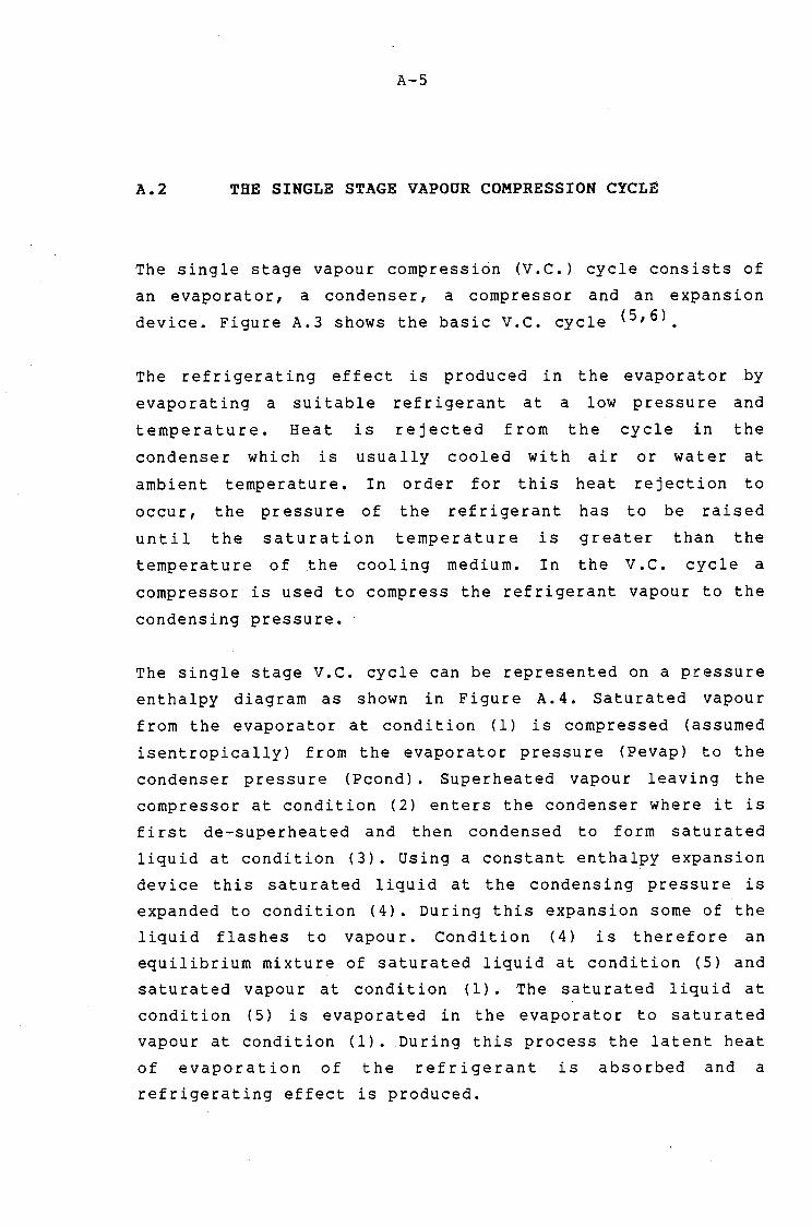
A-5
A.2 THE SINGLE STAGE VAPOUR COMPRESSION CYCLE
The single stage vapour compression (V.C.) cycle consists of
an evaporator, a condenser, a compressor and an expansion
device. Figure A.3 shows the basic v.c. cycle (5,6)
The refrigerating effect is produced in the evaporator by
evaporating a suitable refrigerant at a low pressure and
temperature. Heat is rejected from the cycle in the
condenser which is usually cooled with air or water at
ambient temperature. In order for this heat rejection to
occur, the pressure of the refrigerant has to be raised
until the saturation temperature is greater than the
temperature of the cooling medium. In the V .c. cycle a
compressor is used to compress the refrigerant vapour to the
condensing pressure. ·
The single stage v.c. cycle can be represented on a pressure
enthalpy diagram as shown in Figure A. 4. Saturated vapour
from the evaporator at condition (1) is compressed (assumed
isentropically) from the evaporator pressure (Pevap) to the
condenser pressure (Pcond). Superheated vapour leaving the
compressor at condition (2) enters the condenser where it is
first de-superheated and then condensed to form saturated
liquid at condition (3). Using a constant enthalpy expansion
device this saturated liquid at the condensing pressure is
expanded to condition (4). During this expansion some of the
liquid flashes to vapour. Condition (4) is therefore an
equilibrium mixture of saturated liquid at condition (5) and
saturated vapour at condition (1). The saturated liquid at
condition (5) is evaporated in the evaporator to saturated
vapour at condition (1). During this process the latent heat
of evaporation of the refrigerant is absorbed and a
refrigerating effect is produced.

A-6
FIG A.3 SINGLE STAGE VAPOUR COMPRESSION CYCLE
I Condenser
(2)
Compressor Expansion device
High l pressure
-------------- --------
w comp (1) Evaporator
(4) pressure
FIG A.4 SINGLE STAGE VAPOUR COMPRESSION CYCLE ON A PRESSURE - ENTHALPY DIAGRAM
Pressure (P)
Constant enthalpy expansion
Condenser inlet
p ( (3) (2) cond - - - - - \ -·~---------1,...---___.,.
p evap
I I I I I
h5 I Evaporator inlet
I (4) I I I I I
h4 hl
Ref effect Com
Heat re·ected in the condenser
work
I 1-Isentropic I compression
I I
Compressor inlet
h2
Enthalpy (h)

A-7
The coefficient of performance of a sing 1 e stage vapour
compression cycle has been defined as the ratio of the heat
absorbed in the evaporator to the work supplied to the
compressor. The COP is therefore given by the equation :
COP vc = Oevap/W (A. 4)
Where
COP vc = Coefficient of performance of a single
stage vapour compression cycle.
Qevap = Heat absorbed in the evaporator (J/s).
w = Compressor work (J/s).
But
Where
h· = Enthalpy at cycle point i (J/kg) 1
(Ref er to Fig. A. 4) •
m. 1 = Refrigerant mass flow rate at
cycle point i (kg/s).
i = Cycle point number.
Thus
(A. 5)

A-8
A.3 COMPARISON OF THE V.C. CYCLE WITH THE CARNOT CYCLE
Figure A.5 shows a vapour compression and a Carnot
refrigeration cycle superimposed on a temperature - entropy
diagram.
The isentropic expansion of the Carnot cycle is replaced in
the v.c. cycle with a constant enthalpy expansion. This
results in a reduction in the refrigerating effect. A
constant enthalpy expansion is normally used in real
refrigerating systems because the work which can be
extracted with an isentropic expansion is small and the
additional equipment required for the expansion is not
economically justifiable. Since the partly isentropic and
partly isothermal compression required by the Carnot cycle
is not achievable with real compressors the ideal v.c. cycle
has a completely isentropic com~ression. As can be seen in
Figure A.5 this results in a "superheat horn" on the v.c. cycle. As a result high compressor discharge temperatures
occur and more compressor work has to be performed in the
v.c. cycle than in the Carnot cycle. For these reasons the
coefficient of performance of the v.c. cycle is always
somewhat less than the COP of the Carnot cycle.

A-9
FIG A.5 CARNOT AND REAL REFRIGEP~TION CYCLES ON A TEMPERATURE - ENTROPY DIAGRAM Temperature
(T)
T cond
T evap
Extra heat ~sorbing capacity of the Carnot cycle
Line of constant
enthalpy
Entropy (s)
Real cycle
Carnot cycle
FIG A.6 THE EFFECT OF DECREASING THE EVAPORATOR TEMPERATURE OF A SINGLE STAGE V.C. CYCLE
Temperature (T)
T cond
T evap 1
T evap 2
High compressor discharge temps
~
Heat absorbed is rapidly reduced as the evaporator temperature is lowered
Isentropic compressions
Entropy (s)

A-10
A.4 THE TWO-STAGE V.C. CYCLE WITH INTERCOOLING
Equation A. 3 shows that the coefficient of performance of
the Carnot refrigeration cycle (and thus all other
refrigeration cycles) decreases as :
i) The evaporating temperature decreases.
ii) The temperature difference between the evaporator and
the condenser increases.
Thus for low evaporating temperatures poor coefficients of
performance are obtained with single stage vapour
compression refrigeration cycles. Cycles with two or three
compression stages are therefore used in these cases and
have the following advantages :
i) Increased relative performance i.e. the performance
compared to a Carnot cycle between the end points is
improved.
ii) Increased absolute performance i.e. the performance of
the high and low pressure cycles is improved since the
temperature differences for each are smaller.
iii) The final temperatures of compression are kept within
reasonable limits.
Decreasing the evaporating temperature of a single stage
cycle results in a rapid reduction in the heat absorbed by
the refrigerant, very high temperatures at the end of
compression and increased compressor work. These effects can
be seen in Figure A. 6. With the compressor work increased
and the heat absorbed decreased the coefficient of
performance is substantially reduced as a result of lowering
the evaporator temperature.

A-11
The two-stage cycle is essentially two single stage cycles
arranged so that the heat sink for the low pressure cycle is
the heat source for the high pressure cycle. Figure A. 7
shows a two stage v.c. cycle with intercooling. The system
consists of a condenser, evaporator, flash tank, low
pressure (l.p.) compressor and high pressure (h.p.)
compressor. The flash tank operates at a pressure
intermediate between the condenser and evaporator pressures.
The l.p. compressor compresses the refrigerant vapour
produced in the evaporator and the flash gas from the second
expansion to the intermediate flash tank pressure. The
discharge from this compressor is cooled by bubbling it
through the liquid refrigerant in the flash tank some of
which is evaporated to provide the cooling. The h.p.
compressor takes vapour from the flash tank and compresses
it to the condenser pressure. This vapour includes the l.p.
compressor discharge, flash gas from the first expansion and
the refrigerant evaporated in the flash tank to cool the
l.p. compressor discharge. Figure A.8 shows a two stage V~C.
cycle with intercooling on a temperature - entropy diagram.
It can be seen from this diagram that the "superheat horns"
are reduced and the high compressor discharge temperatures
are eliminated as a result of introducing two stages. The
refrigerating effect is also substantially increased by the
introduction of a second stage. This increase can be clearly
seen in Figure A. 9 which shows the cycle on a pressure -
enthalpy diagram.

A-12
FIG A.7 TWO STAGE VAPOUR COMPRESSION CYCLE WITH INTERCOOLING
(2)
Level float valve
Flash tank
Condenser
Expansion vdevice
(1)
(7)
Evaporator
High pressure /compressor
(6)
Low pressure /compressor

A-13
FIG A.8 TWO STAGE V.C. CYCLE WITH INTERCOOLING ON A TEMPERATURE -ENTROPY DIAGRAM
Temperature (T)
T \ cond
T. t in
T evap
\Line of constant \enthalpy
Superheat horns reduced and high temperatures avoided
Entropy (s)
Refrigerating effect for the single stage cycle
FIG A.9 TWO STAGE V.C. CYCLE WITH INTERCOOLING ON A PRESSURE -ENTHALPY DIAGRAM
Pressure (P)
p cond
P. t in
p evap
I (a) I I I
~rease effect
he of /constant entropy
(1)
Enthalpy (h)
in refrigerating

A-14
The coefficient of performance of the two stage cycle with
intercooling is given by the equation :
Where
COP 2 stage
(A. 6)
= Coefficient of performance of a two
stage v.c. cycle with intercooling
= Low pressure compressor work (J/s).
=High pressure compressor work (J/s).
=Heat absorbed in evaporator (J/s).
Refering to the cycle points labelled on Figures A.7 and A.9
the following equations can be developed for the two-stage
cycle with intercooling :
Wlp = m6·<hG-hs > (A. 7)
whp = mr<h1-h4) (A. 8)
mf = my<ha-h 3 )/(h 4-h3) (A. 9)
me = m~<h 7 -h 4 )/(h 4 -h 3 ) (A.10)
m1 = m6 + mf + me (A .11)
Qevap = m6-<h6-hs > (A. 12)
Qcond = mr<h1-h2> (A.13)
Where
h· = Enthalpy at cycle point i (J/kg). l
mi = Refrigerant mass flow rate at cycle
point i (kg/s)
i = Cycle point number.
mf = Mass flow rate of flash gas from the first expansion (kg/s).
me = Mass flow rate of refrigerant
evaporated to cool l.p. compressor
discharge (kg/s).
Qcond = Heat rejected to the condenser (J/s).

A-15
Subs ti tut ing these equations into equation (A. 6) gives the
equation :
COP 2 stage = (A .14)
A.5 THE VAPOUR ABSORPTION REFRIGERATION CYCLE
The vapour absorption (V.A) refrigeration cycle differs from
the vapour compression cycle in the method used to transport
the refrigerant vapour from the evaporator to the condenser.
Instead of a compressor the V .A. cycle uses a system
comprising of a generator, a pump, an absorber and an
expansion device.
Figure A.10 shows a simple V .A. refrigeration system ( G)
Refering to this figure, saturated vapour from the
evaporator is passed to the absorber where it is absorbed.
The absorbent is a liquid with the property of being able to
absorb vast quantities of the refrigerant. Absorbent from
the absorber, which is rich in absorbed refrigerant, is
pumped to the generator where it is heated. As the
temperature of the absorbent is increased the solubility of
the refrigerant in the absorbent decreases and some of the
refrigerant is released. This refrigerant vapour is passed
to the condenser where it is cooled and condensed. The
condensed liquid refrigerant is expanded to the evaporating
pressure and evaporated in the evaporator to produce the
refrigerating effect, thereby completing the refrigerant
path. The hot absorbent in the generator, which is now lean
in absorbed refrigerant, is returned to the absorber where
it is cooled and allowed to absorb more refrigerant vapour.
It is then pumped back to the generator thus completing the
absorbent path.

A-16
FIG A.10 SIMPLE ABSORPTION REFRIGERATION SYSTEM
w pump
Strong solution
Generator
(3 ) Weak solution
Refrigerant va our
(2~
(1) Expansion devices
Absorber (5)
Refrigerant vapour
Q cond
t' Condenser
(4) Saturated liquid refrigerant
Saturated liquid + flash gas
Evaporator
t

A-17
The only mechanical work input required to this form of the
V.A. cycle is that to the pump which, due to the low
specific volume of the liquid absorbent, is usually
negligibly small. However a considerable amount of low grade
energy has to be supplied to the generator to heat the
absorbent solution. This heat input is by far the largest
energy input to the cycle and the coefficient of performance
of the V.A. cycle is therefore defined as :
COP va = Oevap/Qgen (A.15)
Where
COP va = Coefficient of performance of the vapour
absorption cycle.
Qevap = Heat absorbed in the evaporator. (J/s).
Ogen = Heat supplied to the generator (J/s).
In order to reduce the heat input to the generator and
thereby increase the performance of the V.A. cycle, a
regenerative heat exchanger is usually fitted to the system.
Hot absorbent returning to the absorber is cooled in the
heat exchanger and its heat is transferred to the cold
absorbent being pumped to the generator. This results in
less "new" energy having to be supplied to heat the
generator and the coefficient of performance of the cycle is
therefore increased.

A-18
A.5 MAXIMUM THEORECTICAL PERFORMANCE OF A VAPOUR
ABSORPTION REFRIGERATION CYCLE
In order to establish the maximum theoretical performance of
a V .A. cycle it is necessary to consider the hypothetical
case of a Carnot heat engine, operating between the
generator temperature and ambient temperature, driving a
reversed Carnot engine (heat pump) operating between the
evaporator temperature and ambient temperature. Figure A.11
shows this concept diagramatically.
From Carnot principles the efficiency of the heat engine and
the performance of the reversed heat engine are given by the
equations
Where
~ HE = W/Qgen = <Tgen - Tamb> I Tgen
~HE = Efficiency of Carnot heat engine.
Yl_ REF = Performance of Carnot heat pump.
W =Carnot engine work output (J/s).
=Work input to Carnot heat pump (J/s).
(A.16)
(A.17)
Qevap = Heat absorbed in the evaporator (J/s).
Qgen = Heat SUJ?plied to the generator (J/s).
Tevap = Evaporator temperature ( K) •
Tcond = Condenser temperature ( K) •
Tamb = Ambient temperature ( K) •

A-19
FIG A.11 DIAGRAMATIC REPRESENTATION OF A CARNOT HEAT ENGINE DRIVING A CARNOT HEAT PUMP
T generator
Carnot heat engine
Tambient
Carnot heat pump
T evaporator
w
w

A-20
But from equation (A.15)
COP v.a. = Qevap/Qgen
So from equations (A.16) and (A.17)
And so
Where
COP v.a. max =1HE' lREF (A.18)
COP v.a. max = Teva~<Tgen-Tamb> T gen-< Tamb-Tevap)
(A.19)
COP
COP v.a.
v.a.
= Coeff of performance of V.A. cycle.
max = Maximum possible coefficient of
performance of V.A. cycle.

APPENDIX B
THEORETICAL EVALUATION OF A REFRIGERATION
CYCLE WITH MULTIPLE EXPANSIONS AND COMPRESSIONS
B.l THEORETICAL COEFFICIENT OF PERFORMANCE
In the multiple expansion and compression refrigeration
cycle, as shown in Figure B.l on a pressure enthalpy
diagram, the saturated liquid from the condenser is expanded
to the evaporator pressure in a series of small expansions.
Each expansion resu 1 ts in the format ion of flash gas
(saturated vapour) and saturated liquid at a lower pressure.
The flash gas is separated from the liquid and compressed to
the condenser pressure directly. Less work is expended in
compressing the flash gas from the stage pressures than if
the refrigerant was fully expanded before the flash gas was
compressed to the condenser pressure.
The coefficient of performance of the cycle can be defined
as :
Where
COP multi exp = Oevap/Wtot (B .1)
COP multi exp = Coefficient of performance of a
refrigeration cycle with multiple
expansions and compressions
= Heat into the evaporator (J/s)
= Total compressor work (J/s)
The total compressor work is given by the equation
n
c i=l
aw. l. ( B. 2)

B-2
Where
Wmain = Main compressor work i.e. work to compress
the vapour from the evaporator
dW· 1 = Compressor work to compress
from the 0 th 1 expansion
n = Number of expansion stages
Substituting equation (B.2) into (B.l) gives
COP multi exp = Qevap
n
Wmain + Cdwi i=l
the
(J/s)
flash gas
(B. 3)
From equation (B. l) it can be seen that, as the total
compressor work decreases, the coefficient of performance
increases. As the number of expansion stages is increased,
mo re flash gas is compressed th rough smaller pressure
differentials. This results in a reduction in the compressor
work and an increase in the coefficient of performance. The
maximum possible performance would be obtained with an
infinite number of expansion stages, each with infinitely
small pressure drops.
The ideal compressor work required for each stage can be
calculated from the equation :
Where
dW· = 1 ( B. 4)
dWi = Ideal compressor work for the ith stage
mi =Vapour mass flow rate at ith stage
dhi = Enthalpy rise during ith compression

B-3
The main compressor work i.e. the compressor
compress the refrigerant which is evaporated
evaporatot, can be calculated using the equation :
(B.5)
Where
Wmain = Main compressor work (J/s)
mevap = Evaporator mass flow rate (kg/s)
work to
in the
hi = Enthalpy at cycle point i (see Fig B.l)
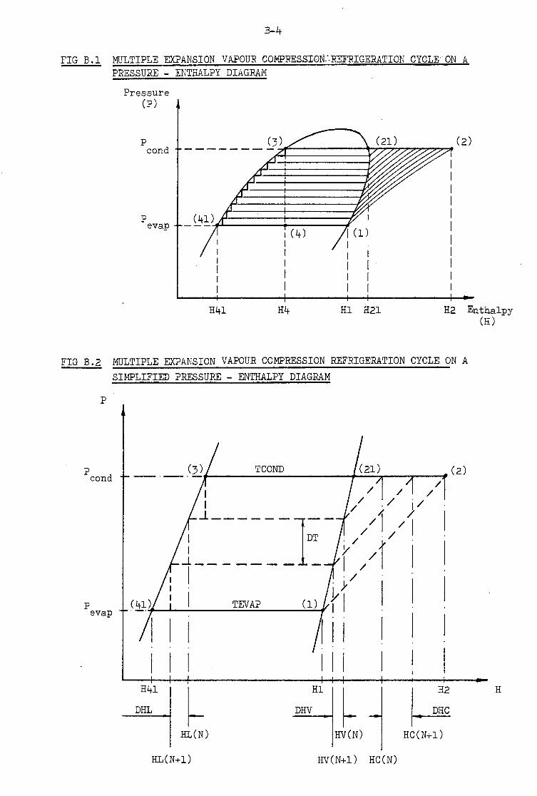
B-4
FIG B .1 MULTIPLE EXPANSION VAPOUR COMPRESSION---REFRIGERATION CYCLE ON A PRESSURE - ENTHALPY DIAGRAM
Pressure (P)
p cond
p evap
H41 H4 Hl H21 H2 Enthalpy (H)
FIG B.2 MULTIPLE EXPANSION VAPOUR COMPRESSION REFRIGERATION CYCLE ON A SIMPLIFIED PRESSURE - ENTHALPY DIAGRAM
p
p cond
p evap
/ I / I / ./ j/
...1 / /, /
:
------1D_T_ //,//'
_l _______ - (/I I
I ·/ ."fl--.....__l ___ TEV_AP __ ......:..........., rt I
I I I 11 I I I I I I I I I
H41
DHL
Hl
~ ~ DHV
HL(N) HV(N) HC(N+l)
HL(N+l) HV(N+l) HC(N)
H

B-5
B.2 DETERMINATION OF THE COEFFICIENT OF PERFORMANCE
Due to the large number of stages and the repetitive nature
of the calculations the determination of the theoretical
coefficient of performance of the multiple expansion cycle,
was suited to being performed by a micro-computer.
In order to calculate the ideal compressor work at each
stage it was necessary to determine the following :
i) The refrigerant vapour fraction for each expansion
stage and hence the vapour and liquid mass flow rates
at each stage.
ii) The enthalpy of the saturated liquid and saturated
vapour at each stage.
iii) The enthalpy of the flash gas from each expansion stage
after an isentropic compression to the condenser
pressure.
It was impractical to obtain all of the refrigerant
enthalpies required, other than those at the main cycle
points shown on Figure B. l, from the pressure - enthalpy
diagram. It was therefore necessary to make some simplifying
assumptions to enable the enthalpies required for the
calculations to be more conveniently determined.
The following assumptions were therefore made
i) The saturated liquid and vapour lines on the·
refrigerant pressure enthalpy diagram were assumed to
be straight over the temperature range of interest.

ii )
B-6
The lines of constant entropy
enthalpy diagram were assumed
parallel in the region of interest.
on the pressure
to be straight and
With the above assumptions, the multiple expansion cycle of
Figure B.l became that shown in Figure B.2. It was then
possible, given the enthalpies at the main cycle points,
i • e • points 1 , 2 , 2 1 , 3 , and 41 , to ca 1cu1 ate any
intermediate enthalpy required using linear interpolation.
Refering to Figure B.2 and the symbols on that diagram the
following equations were formed
(The equations have been presented as use·d in the computer
programme and the syntax therefore corresponds to that of
the BASIC computer programming language.)
On the saturated liquid line :
DT/DHL = (TCOND-TEVAP)/(H3-H41)
Thus HL(N-1) = HL(N) + ( DT*(H3-H41)/(TCOND-TEVAP) )
On the saturated vapour line :
DT/DHV = (TCOND-TEVAP)/(H21-Hl)
Thus HV(N-1) = HV(N) + ( DT*(H21-Hl)/(TCOND-TEVAP) )
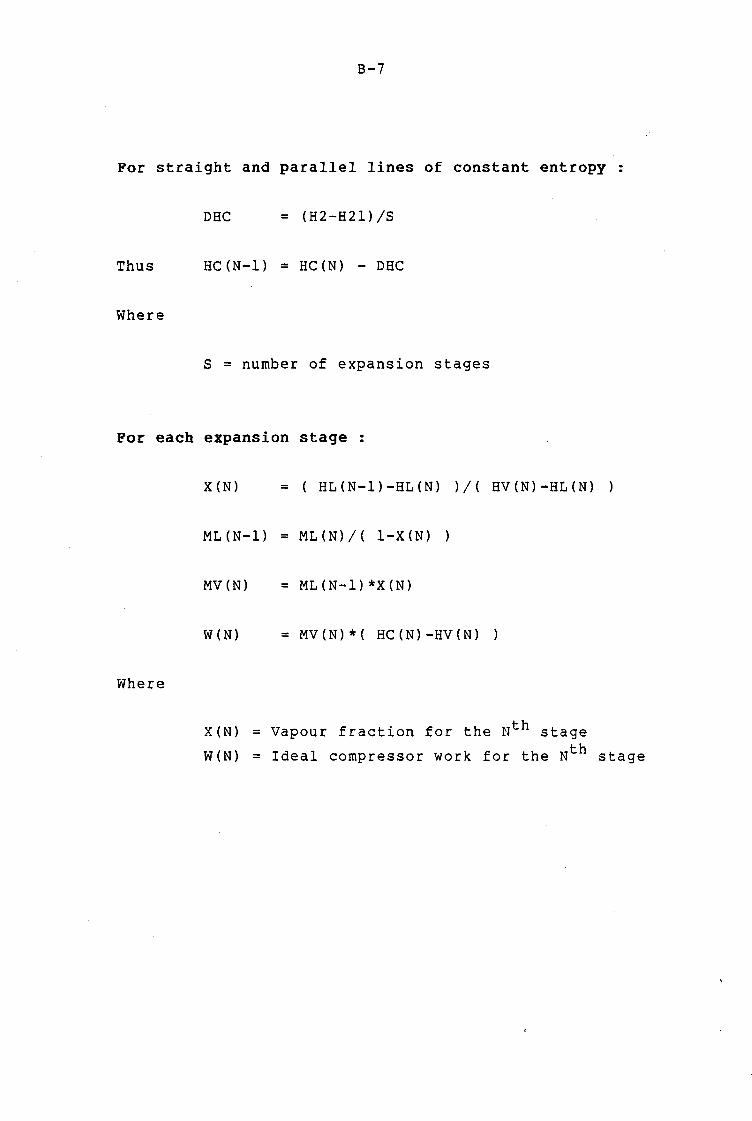
B-7
For straight and parallel lines of constant entropy :
DHC = (H2-H21)/S
Thus HC(N-1) = HC(N) - DHC
Where
S = number of expansion stages
Por each expansion stage :
X(N) = ( HL(N-1)-HL(N) ) I< HV (N) -HL (N) )
ML(N-1) = ML(N)/( 1-X (N)
MV(N) = ML(N-l)*X(N)
W(N) = MV(N)*( HC (N) -HV (N) )
Where
X(N) = Vapour fraction for the Nth stage
W(N) = Ideal compressor work for the Nth stage

B-8
For the evaporator :
QIN = ML(S+l)*(Hl-H41)
ML(S+l) = QIN/(Hl-H41)
WCOMP = ML(S+l)*(H2-Hl)
Where
QIN = Heat into evaporator
ML(S+l) = Evaporator mass flow rate
known flow rate given QIN)
WCOMP = Main compressor work
For the cycle :
COP = QIN/WTOT
COP = QIN/(WCOMP+WTOT2)
Where
COP = Coefficient of performance
WTOT = Total compressor work
(initial
WTOT2 = Sum of all the stage compressor work
The above equations, enclosed in appropriate loops and
supporting routines, were incorporated into the programme
listed in section B.3, _which calculated the coefficient of
performance of the multi -expansion cycle. Details of the
programme have been given in section B.3

B-9
B.3 PROGRAMME LISTING
The programme listed below was used to calculate the coefficient of performance of the multiple expansion vapour compression refrigeration cycle as described previously. Additional coding calculated, for comparison, the coefficients of performance of a Carnot cycle, a single stage v.c. cycle and a two stage v.c. cycle with intercooling. All of the cycles were considered between the same evaporating and condensing temperatures.
The programme required initialisation with the following data
i) The ~vaporating pressure and temperature.
ii) The condensing pressure and temperature.
iii) The refrigerant used and the refrigerant enthalpies at the main cycle points shown in Figure B.2.
iv) The number of expansion stages to be considered
10 REM THIS PROGRAM CALCULATES THE COP OF A REFRIGERATION CYCLE 20 REM EMPLOYING MULTIPLE REFRIGERANT EXPANSIONS, WITH THE 30 REM FLASH GAS BEING COMPRESSED TO CONDENSER PRESSURE FROM THE 40 REM INTERMEDIATE PRESSURES AT WHICH IT IS FORMED 50 REM 60 REM DEVELOPED BY J A BROWNE, OCT, 28/3/85 70 REM REWRITTEN FOR IBM PC 4 OCTOBER 1985 80 I
90 REM DIMENSION ARRAYS 100 I
110 DIM HL(200) 120 DIM HV(200) 130 DIM T(200) 140 DIM W(200) 150 DIM X(200) 160 DIM MV(200) 170 DIM ML(200) 180 DIM HC(200) 190 DIM P(200) 200 I
210 REM INITIALISE ENTHALPIES (OBTAIN FROM RELEVANT P-h DIAG :UNITS KJ/KG) 220 Hl=246.6 230 H2=279.l 240 H21=260.l 250 H3=81.4 260 H4=H3 270 H41=32.6

B-10
280 I
290 REM RECORD DEFAULT REFRIGERANT TYPE & NO. OF EXPANSION STAGES 300 REF$="FREON 22" :S=lO 310 I
320 REM INITIALISE DEFAULT TEMP LIMITS CHOSEN (UNITS - DEG KELVIN ) 330 TCOND=305 340 TEVAP=265 350 I
360 REM INITIALISE DEFAULT CONDENSER & EVAPORATOR PRESSURES (UNITS -BAR) 370 PCOND = 13.l 380 PEVAP = 6.1 390 I
400 REM INITIALISE HEAT INPUT CHOSEN (UNITS ARE KW ) 410 QIN=l! 420 I
430 CLS 440 PRINT "START PROGRAMME EXECUTION" 450 PRINT 460 PRINT "SELECT OUTPUT DEVICE REQD - SCREEN [S],PRINTER [P],DISC [ D] II
470 INPUT A$ 480 IF A$="P" THEN OPEN "LPTl:" FOR OUTPUT AS #1 490 IF A$="D" THEN OPEN "DATAl" FOR APPEND AS #1 500 IF A$="S" THEN OPEN "SCRN:" FOR OUTPUT AS #1 510 PRINT 520 PRINT "DETAILED OUTPUT REQD ?? (Y/N) " 530 INPUT B$ 540 PRINT 550 PRINT "CHANGE PARAMETERS ?? (Y/N)" 560 INPUT C$ 570 IF C$="Y" THEN.PRINT ELSE GOTO 770 580 PRINT "CHANGE NO. OF EXPANSION STAGES ONLY ?? (Y/N)" 590 INPUT E$ 600 IF E$="Y" THEN GOTO 720 ELSE PRINT 610 PRINT "ENTER TEMPERATURES: [TCOND 1 TEVAP] UNITS: KELVIN" 620 INPUT TCOND,TEVAP 630 PRINT 640 PRINT "ENTER PRESSURES: [PCOND,PEVAP] UNITS: BAR" 650 INPUT PCOND,PEVAP 660 PRINT 670 PRINT "ENTER ENTHALPIES : [Hl,H2,H21,H3,H4,H41] UNITS: KJ/KG" 680 INPUT Hl,H2,H21,H3,H4,H41 690 PRINT 700 PRINT "ENTER QIN AND REFRIGERANT TYPE: [QIN,REF] UNITS FOR QIN: KW" 710 INPUT QIN,REF$ 720 PRINT 730 PRINT "ENTER NO. OF EXP STAGES: [S]" 740 INPUT S 750 IF S > 199 THEN BEEP : PRINT "ARRAYS NOT BIG ENOUGH" 760 I
770 REM INITIALISE OTHER VARIABLES 780 DT = (TCOND-TEVAP)/S 790 T(l)=TCOND
GOTO 730

800 T(S+l)=TEVAP 810 HL(l)=H3 820 HV(l)=H21 830 HL(S+l)=H41 840 HV(S+l)=Hl 850 HC(S+l)=H2 860 X(l)=O 870 W(l)=O 880 HC(l)=H21 890 MVTOT=O 900 WTOT2=0 910 P(S+l)=PEVAP 920 P(l)=PCOND 930 ' 940 REM PRINT INITIAL DATA 950 PRINT #1,
B-11_
960 PRINT #1,USING "REFRIGERANT = & QIN = ##.### KJ/S";REF$,QIN 970 PRINT #1, 980 PRINT #1,"ENTHALPIES (KJ/KG) II
990 PRINT #1, 1000 PRINT #1,USING "Hl = ###.#";Hl 1010 PRINT #1,USING "H2 = ###.# ";H2 1020 PRINT #1,USING "H3 = ###.# ";H3 1030 PRINT #1,USING "H4 = ###.# ";H4 1040 PRINT #1,USING "H41 = ###.# ";H41 1050 PRINT #1,USING "H21 = ·###.# ";H21 1060 PRINT #1, 1070 PRINT 11,"TEMPERATURES (KELVIN) PRESSURES (BAR)" 1080 PRINT #1, 1090 PRINT #1,USING"TCOND = ###.# PCOND = ##.#";TCOND,PCOND 1100 PRINT #1,USING"TEVAP = ###.# PEVAP = ##.#";TEVAP,PEVAP 1~10 PRINT tl,USING"DEL T = ###.# ";DT 1120 PRINT #1, 1130 PRINT #1,USING "NO. OF EXPANSION STAGES = ###";S 1140 PRINT #1, 1150 PRINT #1, 1160 ' 1170 PRINT 1180 PRINT "WAIT ....... " 1190 I
1200 REM CALC COP OF MULTIPLE EXPANSION CYCLE 1210 DHC=(H2-H21)/S 1220 ML(S+l)=QIN/(Hl-H41) 1230 Rl=(H3-H41)/(TCOND-TEVAP) 1240 R2=(H21-Hl)/(TCOND-TEVAP) 1250 FOR N=S+l TO 2 STEP -1 1260 IF N=2 THEN GOTO 1330 1270 HL(N-l}=HL(N)+(Rl*DT) 1280 HV(N-l)=HV(N)+(R2*DT) 1290 T(N-l)=T(N}+DT 1300 R=( T(N-1)-TEVAP }/( TCOND-TEVAP ) 1310 LP=LOG(PEVAP)+(LOG(PCOND)-LOG(PEVAP))*R

-------------------------------------------- -
B-12
1320 P(N-l)=EXP(LP) 1330 X(N)=( HL(N-1)-HL(N) )/( HV(N)-HL(N) ) 1340 ML(N-l)=ML(N)/(1-X(N)) 1350 MV(N)=ML(N-l)*X(N) 1360 IF N=2 THEN GOTO 1380 1370 HC(N-l)=HC(N)-DHC 1380 W(N)=MV(N)*(HC(N)-HV(N)) 1390 WTOT2=WTOT2+W(N) 1400 MVTOT=MVTOT+MV(N) 1410 NEXT N 1420 WCOMP=ML(S+l)*(H2-Hl) 1430 WTOT=WTOT2+WCOMP 1440 Wl=WCOMP/WTOT*lOO 1450 W2=WTOT2/WTOT*l00 1460 COPIM=QIN/WTOT 1470 I
1480 REM CALC COP OF CARNOT CYCLE 1490 COPCAR=TEVAP/(TCOND-TEVAP) 1500 I
1510 REM CALC COP OF SINGLE STAGE CYCLE 1520 MTOT=QIN/(Hl-H4) 1530 COPSSVC=QIN/(MTOT*(H2-Hl)) 1540 I
1550 REM CALC COP OF 2 STAGE CYCLE WITH INTERCOOLING 1560 DT2=(TCOND-TEVAP)/2 1570 H8=H21-(R2*DT2) 1580 H5=H3-(Rl*DT2) 1590 H6=H5 1600 H9=(H2-H21)/2+H21 1610 H7=(H2-Hl)/2+Hl 1620 ME=QIN/(Hl-H6) 1630 MCOOL=ME*(H7-H8)/(H8-H5) 1640 MC=(ME+MCOOL)/(l-(H3-H5)/(H8-H5)) 1650 MF=MC*(H3-H5)/(H8-H5) 1660 WLP=ME*(H7-Hl) 1670 WHP=MC*(H9-H8) 1680 COP2SIC=QIN/(WLP+WHP) 1690 I
1700 REM CALC % IMPROVEMENT IN COPMEXP COMPARED TO OTHER CYCLE COP'S 1710 IMOVERSS=lOO*(COPIM-COPSSVC)/COPSSVC 1720 IMOVER2S=lOO*(COPIM-COP2SIC)/COP2SIC 1730 I
1740 REM PRINT DATA TABLE IF REQD 1750 IF B$="N" OR B$="NO" THEN GOTO 1870 1760 PRINT #1, 1770 PRINT #1,"TABLE OF TEMPS,ENTHALPIES & MASS FLOW RATES AT EACH EXPANSION STAGE" 1780 PRINT #1, 1790 PRINT #1, HC X 1800 PRINT #1, (KJ/KG)
#1, #1,
II N MV
II
(KG/S) 1810 PRINT 1820 PRINT 1830 FOR M=l TO S+l STEP l
TEMP PRESS HL HV W"
( K) (BAR) (KJ/KG) (KJ/KG) ( J /S) II

----------------------------------~--
B-13
1840 PRINT #1 ,USING II ### ###.## ##.##AAAA ##.##AAAA
###.## ##.## ###.## ###.##
# # . ###II ; MIT ( M) Ip ( M) I H L ( M) I HV ( M) I HC ( M) Ix ( M) I MV ( M) I w ( M) * 10 0 0 1850 PRINT #1, 1860 NEXT M 1870 I
1880 REM PRINT REFRIGERANT MASS FLOW RATES 1890 PRINT #1, "REFRIGERANT MASS FLOW RATES (KG/S)" 1900 PRINT #1, 1910 PRINT #1,USING 1920 PRINT #1,USING 1930 PRINT #1,USING 1940 PRINT #1,
"M EVAP = ##.###AAAA "M COND = ##.###AAAA "M FLASH VAP = ##.###AAAA
1950 PRINT #1,"COMPRESSOR WORK REQUIRED (J/S) 1960 PRINT #1, 1970 REM PRINT THE VARIOUS COMPRESSOR WORK REQD 1980 PRINT #1,USING "MAIN = ####.## ##.##";WCOMP*lOOO,Wl 1990 PRINT #1,USING "SEC(FLASH VAP) = ####.## ##.##";WTOT2*1000,W2
II ; ML(S+l) II ; MTOT " ; MVTOT
% TOTAL =
% TOTAL =
2000 PRINT #1,USING "TOTAL 2010 '
= ####.##";WTOT*lOOO
2020 REM PRINT COP'S 2030 PRINT #1, 2040 PRINT #1,"COEFFICIENTS OF PERFORMANCE" 2050 PRINT #1, 2060 PRINT #1,USING"COPCARNOT = ##.##";COPCAR 2070 PRINT #1,USING"COPMULEXP = ##.##";COPIM 2080 PRINT #l,USING"COP2SIC = ##.##";COP2SIC 2090 PRINT #1,USING"COPSSVC = ##.##";COPSSVC 2100 PRINT #1, 2110 PRINT #1,USING"IMPROVEMENT IN COP OVER SINGLE STAGE %";IMOVERSS 2120 PRINT #1,USING"IMPROVEMENT IN COP OVER 2 STAGE INTCOOL %";IMOVER2S 2130 PRINT #1, 2140 PRINT #1, 2150 CLOSE #1 2160 PRINT 2170 PRINT "RE-RUN PROGRAMME ?? (Y/N)" 2180 INPUT D$ 2190 IF D$="Y" THEN CLS :GOTO 450 2200 PRINT 2210 PRINT "END PROGRAMME EXECUTION" 2220 END
= ##.#
= ##.#

B-14
B.4 TYPICAL RESULTS PRODUCED BY THE PROGRAMME
PRINTOUT 1:
REFRIGERANT = REF 22
ENTHALPIES (KJ/KG)
Hl H2 H3 = H4 H41 = H21
= 246.6 = 281.5
86.1 86.1 32.6
= 260.5
=
TEMPERATURES (KELVIN)
TCOND = 308.0 TEVAP = 263.0 DEL T = 9.0
QIN = 0.860 KJ/S
PRESSURES (BAR)
PCOND = 13.l PEVAP = 3.5
NO. OF EXPANSION STAGES = 5
TABLE OF TEMPS,ENTHALPIES & MASS FLOW RATES AT EACH EXPANSION STAGE
N TEMP PRESS HL HV HC x MV (K) (BAR) (KJ/KG) (KJ/KG) (KJ/KG) (KG/S)
1 308.00 13.10 86.10 260.50 260.50 O.OOE+OO O.OOE+OO
2 299.00 10.03 75.40 257.72 264.70 5.87E-02 3.12E-04
3 290.00 7.68 64.70 254.94 268.90 5.62E-02 2.81E-04
4 281.00 5.88 54.00 252.16 273.10 5.40E-02 2.55E-04
5 272.00 4.51 43.30 249.38 277.30 5.19E-02 2.32E-04
6 263.00 3.45 32.60 246.60 281.50 5.00E-02 2.12E-04
REFRIGERANT MASS FLOW RATES (KG/S)
M EVAP = 4.019E-03 M COND = 5.358E-03 M FLASH VAP = 1. 291E-03
COMPRESSOR WORK REQUIRED (J/S)
MAIN = 140.25 % TOTAL = 84.73 SEC(FLASH VAP) = 25.28 % TOTAL = 15.27 TOTAL = 165.53
w (J/S)
0.000
2.175
3.924
5.333
6.468
7.382

COEFFICIENTS OF PERFORMANCE
COPCARNOT = 5.84 COPMULEXP = 5.20 COP2SIC = 4.83 COPSSVC = 4.60
B-15
IMPROVEMENT IN COP OVER SINGLE STAGE = 13.0 % IMPROVEMENT IN COP OVER 2 STAGE INTCOOL = 7.6 %
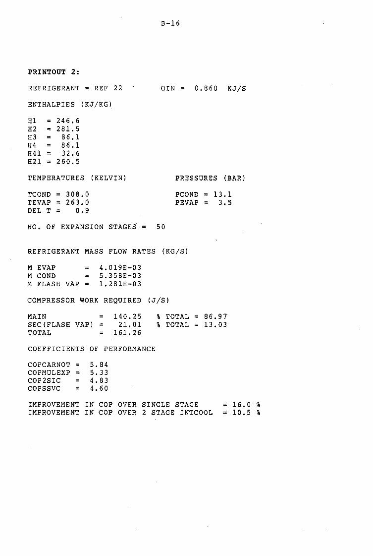
---------------------------- - - -------------
PRINTOUT 2:
REFRIGERANT = REF 22
ENTHALPIES (KJ/KG)
Hl = 246.6 H2 = 281. 5 H3 = 86.1 H4 = 86.1 H41 = 32.6 H21 = 260.5
TEMPERATURES (KELVIN)
TCOND = 308.0 TEVAP = 263.0 DEL T = 0.9
B-16
QIN = 0.860 KJ/S
PRESSURES (BAR)
PCOND = 13.l PEVAP = 3.5
NO. OF EXPANSION STAGE~ = 50
REFRIGERANT MASS FLOW RATES (KG/S)
M EVAP = M COND = M FLASH VAP =
4.019E-03 5.358E-03 1. 281E-03
COMPRESSOR WORK REQUIRED (J/S)
MAIN = SEC(FLASH VAP) = TOTAL =
140.25 21. 01
161. 26
COEFFICIENTS OF PERFORMANCE
COPCARNOT = 5.84 COPMULEXP = 5.33 COP2SIC = 4.83 COPSSVC = 4.60
% TOTAL = 86.97 % TOTAL = 13.03
IMPROVEMENT IN COP OVER SINGLE STAGE = 16.0 % IMPROVEMENT IN COP OVER 2 STAGE INTCOOL = 10.5 %

PRINTOUT 3:
REFRIGERANT = REF 22
ENTHALPIES (KJ/KG)
Hl = 246.6 H2 = 281. 5 H3 = 86.1 H4 = 86.1 H41 = 32.6 H21 = 260.5
TEMPERATURES (KELVIN)
TCOND = 308.0 ·TEVAP = 263.0 DEL T = 0.5
B-17
QIN = 0.860 KJ/S
PRESSURES (BAR)
PCOND = 13.1 PEVAP = 3.5
NO. OF EXPANSION STAGES = 100
REFRIGERANT MASS FLOW RATES (KG/S)
M EVAP = M COND = M FLASH VAP =
4.019E-03 5.358E-03 1. 280E-03
COMPRESSOR WORK REQUIRED (J/S)
MAIN = SEC(FLASH VAP) = TOTAL =
140.25 20.77
161. 03
COEFFICIENTS OF PERFORMANCE
COPCARNOT = 5.84 COPMULEXP = 5.34 COP2SIC = 4.83 COPSSVC = 4.60
% TOTAL = 87.10 % TOTAL = 12.90
IMPROVEMENT IN COP OVER SINGLE STAGE = 16.l % IMPROVEMENT IN COP OVER 2 STAGE INTCOOL = 10.6 %

----------------------------------------. ---------==-~---
PRESSURES
LOCATION
Condenser Stage 1
· Stage 2
Stage 3
Stage 4
Stage 5
Generator Absorber
TEMPERATURES:
LOCATION 1
2
. APPENDIX C
** EXPERIMENTAL DATA SBKET ** MULTIPLE EXPANSION - ABSORPTION MODE
PRESSURE (bar)
Gauge Abs
8,50 9,50
7,40 8,40
6,40 7,40
4,50 5~50
2,70 ;,70
1.50 2.50
E,50 9,50
1,10 2,10
mV Deg C 0,60 14,81
0 52 12.84
TEMP (Deg Ce1)
21,32
16,91
12,51
2,66
- 9,99 -19,7-:i;
------
LOCATION 8
9
SHEET No. DATE Atm Press
REMARKS
.2.A . .•.•..••
.2.6/?/.~6 .....
.7.5?,? mm Hg
•0. 1 ~~~ bar
.~~q ,bµ~~~t. ~. Q ,,45. ~g •...•
f~~~mp~t~~ ?~t.qt, t9Q ft~g.~ 99111E .irt~t . .Pf~fls.ur~. =; .1?. :es.i
mV Deg C ' -0.31 - 7,65
-0.72 -17.78
3 -0,62 -15,31 10 4,03 99,51 4 -0,40 - 9,88 11 0,63 15,56
5 0,60 14,81 12 0,61 15,06
6 0,48 11,85 13 0,74 18,27
7 0,09 - 7,65 14 0,63 15,56
COOLING & HEATING WATER FLOW RATES
MASS BUCKET TIME FLOW RATE + WATER (Kg) (mins) (Kg/s)
Condenser 6,24 9,50 10,158 x 10-3 Evaporator 5,64 ;,oo 28,833 x 10-3
Absorber ;,96 3,00 _-z
19, 500 x 10 _,
POWER INPUTS
MASS DIST SPEED ELEC POWER (kWh) TIME (Kg) (mm) (rpm) Start End Start End
Compressor 0,799 161 1470 8518,040 8518,342 15h30 16h30 Pump --- --- --- 1291,965 1291,977 15h30 16h30. Heater --- --- --- 3817,347 3817,424 15h300 16h00

C-2
** EXPERIMENTAL DATA ,SHEET ** SINGLE EXPANSION AND COMPRESSION MODE
PRESSURES
LOCATION PRESSURE -, (bar)-
Gauge Abs '
Condenser E,50 9,50 " --
TEMPERATURES:
LOCATION mV Deg C
1 0,59 14,57 2 0,51 12,59 3 -0,62 -15,31 4 -0,41 -10,12
12 0,61 15,06
13 0,77 19,01
14 0,66 16,30
TEMP (Deg Cel)
21,32 -
r
SHEET No. DATE Atm Press
REMARKS
2B . ......... . 26/8/86
. ~5.2.1 ? mm Hg
. ~,,9~~ bar
.~~~ .b.u;~:~ .=. ?'.~5. ~~ ..... ·.c?~"I2 • i.n~~~ .P.r;~~ .=. ~~ .P!3~ •.
• • •. • • ti •••••••••••••••••
COOLING & HEATING WATER FLOW RATES
· MASS BUCKET TIMK FLOW RATE + WATER {Kg) (mins) (Kg/s)
Condenser 11·,10 12,00 1'4,.792 x lo-3
Evaporator :5,54 , ' 3,00 28,278 x lo-3 ,
POWER INPUTS
MASS . DIST SPEED ELEC POWER {kWh) TIME . (Kg) . (mm) (rpm) · Start End Start End .
Compressor 0,799 158 1465 8518,455 8518,610 16h50 l?h20 ...

PRESSURES
LOCATION
Condenser Stage 1
Stage 2
Stage 3
Stage 4
Stage 5
Generator Absorber
TEMPERATURES:
LOCATION 1
2
3
4
5
6
7
** EXPERIMENTAL DATA SHKET ** MULTIPLE EXPANSION - ABSORPTION MODE
PRESSURE (bar} TEMP
Gauge Abs (Deg Cel}
E,30 9,30 20,39
7,30 E,30 16,70
5,90 6,90 10,22
4,30 5,30 1,53
2,50 3,50 -10,73
1,50 2,50 -19, 73
E,30 S,30 ---1,10 2,10 ---
mV Deg C LOCATION
0,56 13,83 8
0,47 11,60 9
-0,76 -18,77 10
-0,55 -13,58 11
0,59 14,57 12 0,38 9,38 13 0,00 0,00 14
SHEET No. DATE Atm Press
REMARKS
7iA . ,. • ........ . . ?~f8/?~ ... . . ?~3.,? mm Hg . ~ •. ~o;i- bar
'1·:3,s~ '·~\C:"=:'~ .=. ?? ~~ ~f' • • ' ' Ther~ostat set at 120 de~ C ..................... ~ .. Corr.p inlet press= 19 psi ........................
mV Deg C
-0,44 -10,86
-0.74 -18.27 4,74 117,04
0,59 14,57
0,57 14,07
0,70 17,28
0,65 16,05
COOLING & HEATING WATER FLOW RATES
MASS BUCKET TIME FLOW RATE + WATER (Kg) (mins) (K.g/s}
Condenser 4,.'.'4 4,00 ·z,
16,208 X 10-_,,
Evaporator 5,36 3,00 27,272 X 10-3
Absorber 5,S6 _-:,:
5,00 18,367 X 10.,,
POWER INPUTS
MASS DIST SPEED ELEC POWER (kWh} TIME (Kg) (mm) (rpm) Start End Start End
Compressor 0,799 159 1465 8519,171 8519,490 11h15 12h15 Pump --- --- --- 1291,991 1292,003 11h15 12h15 Heater --- --- --- 3817,779 3817,864 11h15 12h15

C-4
** EXPEBIMKNTAL DATA SHEET ** SINGLE EXPANSION AND COMPRESSION MODE
PRESSURES
LOCATION PRESSURE (bar) Gauge Abs
Condenser 8,40 9,40
TEMPERATURES:
LOCATION mV Deg C
1 0,55 13,58 2 0,46 11,36
3 -0,76 -18,77
4 -0,57 -14,07
12 0,57 14,07
13 0,71 17,53 14 0,64 15,80
TEMP (Deg Cel)
21,11
SHEET No. DATE Atm Press
REMARKS
. 3.~ ••.•....
.~7/~/~q ....
. 7.53., 9 mm Hg
.:i.,.opi bar
.~~~ _b_u~i;~t. :=. 9,.4.5. l:e; ..... Comp inlet press = 19 nsi .................. _. ....
COOLING & HEATING WATER FLOW RATES
MASS BUCKET TIME FLOW RATE + WATER (Kg) {mins) {Kg/s)
Condenser 5,25 5,00 16,000 x 10-3 Evaporator 4,65 3,00 23,333 x io-3
POWER INPUTS
MASS : DIST SPEED ELEC POWER (kWh) TIME {Kg} . {mm} (rpm) Start End Start End .
Compressor 0,799 161 1471 8520,124 8520,362 14hl5 15h00

C-5
** XXPERIMENTAL DATA SBEKT ** MULTIPLE EXPANSION - ABSORPTION MODE
PRESSURES
LOCATION PRESSURE (bar)
Gauge Abs Condenser 8,50 9,50 Stage 1 7,50 8,50 Stage 2 5,70 6,70
Stage 3 4,40 5,40
Stage 4 3,00 4,00
Stage 5 1,50 2,50
Generator 8,50 9,50
Absorber 0,60 1,60
TEMPERATURES:
' LOCATION mV Deg C 1 0,55 13,58
2 0,44 10,86
3 -0,79 -19,51
4 -0,56 -13,83
5 0,63 15,56
6 0,37 9,14
7 0,04 0,99
TEMP (Deg Cel)
21,32
17,12 9,18
2,37
- 7,71
-19, 73
------
LOCATION 8
9
10
11
12
13
14
SHEET No. DATE
. Lt~ ....... .
Atm Press . ~8/J3/6q .... • 7.5.4., ? mm Hg .~,.09? bar
REMARKS .M.a~i;; • b.u.c~~~ .=. 9 ~ ~5. ~~ ..... .c~rp"R • i_nf.~~ .P.r~~~ .=. ~~ .P.S~ •.
Thermostat set at 120 deg C ...................... '
mV Deg C ' -0,32 - 7,90
-0,74 -18,27
4,77 117,78
0,59 14,57
0,59 14,57
0,73 18,02
0,68 16,79
COOLING & HEATING WATER FLOW RATES
MASS BUCKET TIME FLOW RATE + WATER (Kg) (mins) (Kg/s)
Condenser 6,64 7,00 14, 738 x 10-3
Evaporator 7,03 6,oo 18,278 x 10-5
Absorber 2,26 2,00 20,083 x 10-_'.)
POWER INPUTS
MASS DIST SPEED ELEC POWER (kWh) TIME (Kg) (mm) (rpm) Start End Start End
Compressor 0,799 157 1470 8520, 603 8520,920 lOhOO llhOO
Pump --- --- --- 1292,019 1292,027 lOhOO llhOO
Heater --- --- --- 3818,285 3818,373 lOhOO llhOO

PRESSURES
LOCATION
Condenser
TEMPERATURES:
LOCATION 1
2
3
4
12
13
14
C-6
** EXPERIMENT.AL DATA SHEET ** SINGLE EXPANSION AND COMPRESSION MODE
PRESSURE (bar) Gauge Abs
8,50 9,50
mV Deg C
0,55 13,58 0,42 10,37
-0,80 -19,75
-0,58 -14,32
0,58 14,32
0,73 18,03
0,70 17,28
TEMP {Deg Cel)
21,32
SHEET No. DATE Atm Press
REMARKS
.• 4!3 ...•.••.
. .2~/.~/.8~ ....
. .71~ '· 2 mm Hg
.. 1,,9q2 bar
~~s. ?~~1:e.t. :' . ~, .4! . ~g ..... . 9<?1T!P. ~:r;q~t. F:r~s.s. ;: . ~9.P~L ..
COOLING & HEATING WATER FLOW RATES
MASS BUCKET TIME FLOW RATE + WATER (Kg) {mins) (Kg/s)
Condenser 3,35 4,00 12,083 x 10-3
Evaporator 3,91 4,00 14,417 x 10-3
POWER INPUTS
MASS . DIST SPEED ELEC POWER (kWh) TIME . (Kg) . (mm) (rpm) Start End Start End .
Compressor o, 799 157 1470 8521,231 8521,305 12h00 12hl5

THERMOCOUPLE No.
1
2
3
4
5
6
7
8
9
10
11
12
13
14
C-7
** THERMOCOUPLE LOCATIONS **
LOCATION
Evaporator heating water inlet
Evaporator heating water outlet
Evaporator temperature
Evaporator vapour outlet
Stage 1 of expansion column (top)
Stage 2
Stage 3
Stage 4
Stage 5 of expansion column {bottom)
Generator
Absorber
Condenser cooling water inlet
Condenser cooling water outlet
Ambient temperature

C-8
International Standard Thermocouple Tables for
Nickel-chromium/Nickel-aluminium
.-Reference junction at cf deg c
d~ d~ I
c 0 1 2 3 4 5 6 7 8 9 10 c -l•O -····· -····· -•.119 -•.74) -•.7•• -•. 792 -"·117 -··•-1 -····' -····· -•.912 -1"0 -uo .... 10 -··•>1 -··••l -····· -•.!tlS -4e!t41 --.s.1 -•.!t93 -•.611 -····· -····· -uo -uo -•,UI -•.1•• -•.19) -•.221 -•.z.r.a -•.l16 -•.101 _.,,no .... )51 -•.l•• -•·•10 -120 -110 -J,IS2 -J.Hl -J.910 -J,919 -J.9H -J.997 -",OH _.,,on -•.081 -•.J.10 -•.Ill -110 -100 -J,SSJ -J.SI• -J•U• ·l·•" -J.67• -1.10 .. -3,7) .. -l.76• -J. 79l -J.12l -J.1'12 -10')
•90 -J.Z•Z -J.27• -J,JOS -J.]J7 -1.1•• _,. J99 •le•lO -1 ... •1 -J.•92 -1.sn -J.SSJ -9o
-•o -2.•20 -2.n1 -2.915 -J.011 -J,OSO -J.012 -J.lU -J.1•7 -J.179 -J,211 -J.Z•l -•o -70 -2.s1• -2.•20 -2.65• -2 .u1 -2. 721 -2,75• -2.111 -2.121 -2·"" -2.111 -2.920 -10
-•o -Zo24J -2.211 -2.Jll -2.1•1 -2.111 -2.•1• -2.•SO -2·••• -2oHI •2.SH -2oSH -•o -so -1.11• -10925 -lo961 -lo996 -2oOJ2 -2o0•7 -2ol02 -z.u1 -201 n -2.201 -2.2 .. 1 -so
-•o -lo527 -loS•J -lot.oo -l.t.J6 -1.•TJ -1.709 •le 74!t -1.711 -1.111 -1.asJ -1.H9 --o -10 -ion• -1.19) -1.231 -lo261 -1.305 -1.3•2 -1.]79 -1 ... 16 -1 ... H -l.4t90 -1.527 -Jo -20 -o. 717 -o.1i. •OelS• -0.892 -Oo9JO -o.••• -1.oos -1.0•l -1.011 -1.111 -1.u• -20 -10 -ooJ92 -oo•n •Oe't69 -o.so1 -0.547 -o.s8' -0.62• -0.662 -o. 701 -o. 739 -o. 711 -IC
- 0 o.ooo -000>9 -oo:l79 -OollA -Oo 157 -o.197 -Oo23• -o.2n -0.31• -o.JSJ -0.~•2 -" 0 OoOOO OoOJ9 Oo079 Oo119 001se 0.191 Oo238 0.211 0.111 J,JH o. )97 0
10 OoJ97 o.•17 o.•11 oosP OoSF o.~91 o.oH 0.011 o.11s o. 7~8 o.19e IC lO 0.798 a.en 0.119 Oo919 Oo9o0 1.000 1.~ .. 1 1.oa1 1.1u 1.1•2 1.20J <o JO 1.201 1.2 ... 1.2u loJZS 1.3 .. 1·•07 1 ...... l.•89 1.529 1.570 1.1111 >O
•0 1.•U 1.052 1.6i9J 1. ""
1.1111 1.111 1.oe 1.899 l.9•U 1,981 2.c21 -c
'O 2.022 z.06• 2.105 Zo146i 2.111 2.229 z.210 2o l12 2.JSJ z.Jh 2.•l• so
•O 2.•l• 2 •• 11 ZoS19 2.s•o 2.601 z, .. , 2 ..... 2.726 z. 7'7 z.ao9 2.no 110 70 2.150 20892 2o9JJ 2o97S J.016 J.OSI 1.1~0 3.l•l JoUl J.22 .. ,., .. TO 10 J.2•• )0307 l.3•9 J,)90 J.•32 , ... n ),515 J.Ho J.'98 j,0)9 J.1111 eo 90 J.Hl Jo 722 .J.76• J.IOS 1.1•7 ~ .... l.930 1.911 '-•Oli ... o~- •·09~ •o
100 •.09§ ... 1J7 •.171 ... 219 •·Z•l •• JOZ •.l•J •.ll• .... .z• ..... 1 •• 501 100 110 •• so• .. , .. ••S90 ... 632 ••• 1, •• 11• .. ,,~ •• 796 41tel37 ... 111 ... 919 110
120 •.919 •·••o 50001 s.0•2 ,.oe1 5.12• )·1•• s.zo5 '·1•• ~.287 S.327 120 no 5oll1 5.3 .. s.•o9 Sot.50 S.•90 s.n1 s.sn 5·•12 ,,.,2 , ... ,
'· 7]J 130 140 5. 7JJ 5.774 !1.11• '·"' 50195 5.9). 5.9n 11.01• 0.057 11.097 o.137 1-c
150 •• 1J1 •• 111 •• 211 60251 •oZH .. ,,. ••HI· •·•lt 6009 •·•99 .. ,,, 150 t•o •• ,,9 .. ,,. ••• 19 •o09 ••••• •• 7Jt •• 779 11.119 o.lt9 6.199 •• 939 160 170 •• 919 •·•1• ToOl9 lo059 70099 1.11• 7,179 7.219 1.1'9 7.299 7.HI 170 110 7.JJI 7.J71 7.•11 1 ... ,. 1 ..... 1.t:JI 7,571 1.01• 7 • .S• 7.Dfil 1. 7]7 1ao 190 1.111 1. 711 1.111 1.01 7.197 1.911 1.n1 1.011 a.osr a.o97 1.u1 190
200 1.1J7 1.111 1.2 .. loH• 1.2•• 1.3,. lol7• 1.•I• .. ..,. ••• 97 I.SH lOO 210 1.537 a.s11 ••• 11 80657 .... , •• 7)7 1.111 1.111 a.n1 , .... .. ~,. 210 220 1.01 1·.971 •.011 9e051 90099 9oUt •.179 90220 9.2bu r;i.~oo '·J•l 2<0 230 9o l•l 9oJll .... 21 •·••.Z 9oS02 9o54J 9.513 '·•2• ••••• 9o70S .. , .. ~ 2JO 240 9o70 .. ,.. 9.IU 9olU 9.907 ••••• t.919 I0.029 10.010 10.111 10.u1 i-o
250 10. u1 10.ltZ l0o2JJ 10.21• IOoJU 100]'5 10ol9• l0.•17 10.•711 100519 10.S•O 250 HO 10.s•o 10.1100 10 .... 1 1oou2 10o7ZJ 10. , ... 10.105 10.••• 10.111 10.921 10.•09 zoo ZTO 10.9•• 11.010 11.051 11.093 11.u• 11.1n 11.21• 11.257 11.291 11.))9 11.Jll 210 ZIO 11. lll 11.02 11.•u 110504 11.5•• l1oH7 11 •• 21 11 •••• 11. 711 11.752 llo 79) 2'0 ZtO 11. 79) 11.u, 11.11. 11.tu 11.n9 12.000 12.0•2 12.ou 12.125 12.1 .. 12.201 2ql)
JOO 12.201 12.2•• 12,290 llolJZ 12.]TJ llo•U u ... ,. u ..... lloU9 12.511 12.•lJ JOO 310 lZo•U u .... 12 o 70• 12. 74 7 12. 719 u.111 12,112 llo914 u •• ,, 12.997 1 J.OJt HO JZO u.o,. lJoOIO I Jo 122 lJo164 lJoZ05 Uol47 u.2n UolJl IJoJ72 lJ.•1• 1, •• ,. 320 JJO Uo"56 lJo•t7 lJoH9 13.511 u.•ZJ u ••• , Uo?o• 1).7•1 u.190 u.nz u.11• JJO J40 u.11• Uotlt IJ.951 1Jo9'9 l•.O•I l•oOIJ l•oUS 14o1U l4olOI l"ol50 l•·l•l , .. 0
Absolute thermocouple e.m.f. In Millivolts
Code
K TC LTD PO BOX 130, CHESTERFIELD, ENGLAND Telephone 0246 453315 · Telex 547748 PROBE G

SC~ANGE
EN
THA
LPY
(B
TU
/lb
Abo
ve S
atur
ated
Liq
uid
ot
-40
•F)
n-T
'T""
'1rr
-T-r
Tl'
T-i
-i--
rn-r
r=ih
-,,n
eoT
-r.,
,...
..rr
90
T:t
::p
,...
..rr
in::
ii""
13
0 14
0 1!5
0 l6
0 ~ J)(I~
Tem
pera
ture
in
"Fah
renh
eit
Vol
ume
In c
u It
/ lb
I•
.,.
v ,...,0
["
~ ~ ,...,, ])
(
L'
170
:Jo
.
N.0
·'1"'
.....
.
y llO
diaT=
~~DX>
i"
20
00
Ent
rapy
in
BT
U/
lb "
R
.... Q
ualit
y in
Wt
"lo
'=m
1111
1111
1111
1 um
mrt
N..~
~ ~~ 10
00 .
~IOO
;'t:l 6
00
1/1
/ '")
()1
I I
I I
I I
I I
I I
I I
I I
II V
I.I
30
0
20
0
'i
...... .s 10
0
u
~v
1~rvrttft
.8
b¥ II
J.I
.... Ji
"
I)
IN ~
" I'
IZ
I:
~ ~ D
I
81:
~-~'hv
v =
80
!:
) --
--h~rt'
W6
0
1/1
11
~l-1
I l('~t
~ '"
' "'
J I
I II
~ 11
> .fl
)II
, ii
II I.
If
) 40
~
--0
' J
..
0 ~
30
._
!~-j
··
) _ _
/,_
_/
. , !
• : 11
I-
-11
I:!:'
20
~-I
-;z.
J ;
I J
Li u
u .
c:i-J·
=>
I I/
I/
I
~ ~~--~.
·i·, I
• I
I !YI
~111 1 ~11
1 ~I I *I
, 6.
0 I
I I
I ~
I I
_I
... UV-UJ~~~
~~
.....
ill
It
·+-
'.U
.-
0
.v
.II ~R
I.I
J; ~
II
1,
,/
1, v
JZb
I./
v
J)c
v
~~
tft -V
I Iv
/W
-\/{
"'
/ ,;
,;
.. ..
I
/ I/
v r~u
J.
v IA
] [/ v
..I
v .....
1-I\
1-a.-
·u
y y IY
~J.
J. y
()'
40
0
30
0
200
• ~ ....
IOO
JI
IO
::::::
LA""
ZlJ
Ill
IO
a:
J m
....
,,, 4
0
"''
. '49
30
f ""
• ~m~
10
~
80
.., ~ao
.....
..... 1-
........
g 1
1
·eo'
I',
~
4.0
;!$
II
_ !
'°'.
V.
V
·~~ .
,
I U
_
. I.
/ ..
_,.
. 1
, 8~ \l
oUJli
lE
30
3 ·0
_,...
, I
i~ i.1
.. 3
11
1
IOO
I J
• ·-
I "
..
[,/
, ....
. ,,
:..-
...
..
IA'
~
[,/
II
r/.
""
2.0
I I
, i
I '
.I
~ za
j
I 'L
-
,,
'-'
I.I
"'
I '
j .,
, ..
l I
I.I
n.
.. I
I I
I II I
I
• I
) It
!;
' -"
~ '
' '_,
-'
l't
10
·ix
!?
;:;,
•
ill :~
' ,
120
""1
-"
" II
' '
' ~"'"
' D
~
,, ~
~
l70
. !of
_ . ..-
) ....
. ~..
. ....
~
0.8
0 1
' ..
• I
c -
J "''
~
!ii.
0.6
-, I
1£.
1.1 v:
,,
i Ill
L·!<I
< '
~~
11
II
,,
-1'
11
, I;
I
. I
~
~
I I
V
[,/
03
1
'0
•I""
-IL
II
0 11
-IJ
1 I
I :~ -
20
0 20
4
0
60
80
90
SCAL
E I CH
AN
G!
llO
,, v
~
v 10
0 11
0 12
0 13
0 14
'0 15
0 16
0 E
NTH
ALP
Y (
BT
U/l
b A
bove
Sat
urat
ed L
iqui
d a
t·4
0•F
) l9
0
1.0
QI
GS
CM
o.s
'llJl,0
2
? '°

C-lC
Refrigerant 22 (ChlorodiAuoromethane) Properties of liquid and Saturated Vapor6
I I / Oen-
l'reuure cu lb/cu Siu/lb 8tu/(/b) (ol!) Preuure cu lb/cu Stu/lb ft/lb It Temp ff/lb It
Entropy .. 81u/(lb) (0 R)
Temp F
Volume 'IOensily Enthalpy•• Entropy•• Volume sity Enthalpy••
I Vapor / liquid liquid I Vapor Uquid j Vapor I F • • Vapor liquid liquid Vapor Liquid I Vapor
p1ia psi; v, 1/v, __ h_1_ -"-•_ •t /_•_•_ psia psi; v, 1/Y/ ht Ii, If S.
-150 0.271&3,29.36816",!41.23 198.236/-25 974/ 87.521 -0.07147/0.295011 4-4 89.177 H.48ilO.IH448 1178.770122.558108.4720.04855/0.21912
-145 0.34999129.20861" lll.34 97.6001-24 8511 88.100 -0.06787l0.:!J1D6/ 46 \12.280 77 . .51>4/0.5~422 78.526,23.12Jll08.6340.049670.21876 -140 0.'469229.01126° 88.5.12 97.3631-23.725 88.6l!ll-0.06432:0.287Z9 48 95.463 80.7670.57476 78.2801:!3.7011108.7950.050790.218311 -lM 0.56584 28.761114° i0.981 196.922 -22.5~ 8\1.2631-0.0608:!I0.~836}1 I I -130 0.71060 28.47441° 57.356 96.4801-21.463 89.8481-0.0573610.280:!7 50 98.727 84.0310.5SIIOfl 78.033 24.275 108.953 0.051900.21803 -125 0.88551 28.11829° -16.692 96.0351 -20.326 90.43:ll -0.053\14 0.27700 52 102 .07 87 .38 ,0 . .53808 77. 784!24.8511109.109 0.05301 0.21768 -120 1.0954 27.6910° 38.280 i95.587 -19.185 91.0:!0I-0.050550.273881 54 105.50 00.31 0.52078 77.5.14125.4:!'.l 109.2630.054120.21732 -115 1.3455 27.1818° 31.5\14 '95.137 -18.038 91.6081-0.047~0.27000 56 109.02 94.32 /0.50414 77.:!82126.008,109.4150.055230.21697 -110 1.6411 26.57!!8" w.::-12
194.684 -16.8661 92.19r, -0.0433910.:!6805 ss 112.fi2 97 .v3 ,0.-18813 11 .028126.5891109.564 o.05634 0.21662
-105 1.IIII03 25.868r ::1.9ao ,94.22s -15.728/ !):l.783 -0.040600.25533/ 60 116.31 101.62 10.41212 .76.773121.1121109.11210.0574510.21521 I I , i 62 l'.!O.O'l 105.39 i'),4.5788 :76.51527.75il109.857/'0.05M50.21592
-100 2.398.1 25.036.1° 18.4.1'.l 93.7701-14.5641 93.3711-0.0373410.2112741 64 12:l.9fi 10~.'.!6 '0.44358 '76.257',:!8.3441110.0000.0596/l 0.21558 - 98 2.579~ 24.66S8° i 17.2:.!'.! ,V:l.585J-14.0~71 93.G06i-0.03605i0.26173! 66 'll:!7.32 113.:.!2 j0.421181 t75.996i28.932,110.140!0.0I\Oi6i0.21524 - 116 2.7724 21.:.!765" !G.104 ·n.-!01!-13.6281 93.840, -•J.0347610.260741 68 131.97 117.:.!S 10.41653 '75.733i"2'J.5:!3lltu.27810.D61!!6I0.21490 - 94 2.9768 2:i.800-1• 15.072 :'.)3.2151-13.1581 94.075i -0.0.1:!47,0.25\177: I I I I - 92 3.1934 j~{.ll"}~:,_·1: 14.118
193.030 -12.6881 !14.30,1· -0.03219 0.25&111 70 1311.12 121.4310.40373 75.469 30.116 110.414 O.Oll2!!6i0.21456
- 90 3.--12:!'J -- .,. 13.235 192.8431-12.2!61 94.544 -0.030910.257871 i2 140.37 ,125.67 0.39139 75.202i30.710l110.547'10.ll64G6I0.:.!!-12:! - 88 3.6657 22.4579" 12.417 192.657 -ll.~-13194.777 -O.O~J630.~5695I 74
1144.71 113U.Ol 0.37949 1~4.:J34!_31.3071110.67i0.065,l,6'10.~l~8~
- 86 3.9224 21.93:i2° 11.659 ,92.469 -11.-68 95.011 -0.0283610.-56041 76 149.15 134.45 0.36800 1,4.664,31.9061110.8050.066_60._13~" - 84 4.1936 21.382\1° 10.955 :92.282 -10.793 95.:.!44 -0.0270~0.25515 78 153.69 138.99 0.35691 74.39li32.506il!0.930_0.0673610.21321 - 82 4.4800 20.7\198• 10.302 !92.01!3 -10.316 95.478 -0.025830.25--128 80 158.3.1 143.63 0.34621 IH.116,33.10\lllll.05210.0684610.21288
~ 82 163.07 148.37 0.33587 !73.839!33.714llll.17ll0.06\l,560.21255
- 80 - 78 - 76 - 74 - :-2 - 70 - 68 - G6 - 64 - 62
4.7822 5.1007 5.4-163 5.7896 8.1614 8.5522 6.9628 7.3939 7.8463 8.3208
20.1846· 19.5361° 18.8528° 18.1334· 17 .3766· 16.5809· 15. 7449• 14.8671· 13.9460· 12. 9800·
- 60 8.8180 11.9677° - 58 9.3388 10.9074° - 56 9.8&1\I 19. 7,175• - 5.i 10.45-1 8.636° - 52 11.051 7 .42:! 0
- 50 j11.6H I 6.15--1°
: ~ 1lf~~ I tm: - H 113.712 2.002" - 4:! 14.-151 0.498°
- 40 15.222 0.52f\ - ~8 16 .O~i I. ~2S
u6116.85q I 2.ln1 34 17.72!> 3.W2 32 118.63.l 3.937 ~_.0
8 12019.~~39
I 4.877 :!6 !21.564
5.8
5.1
~ .. l:!:!.011 I ~:~~~ 22 '23. 711 19 .015
:!() 124.845 10.1-19 18 t2ti.020 [11.324 16 127 .239 112 .543 14 :~8.501 13.805 1:! 129.809 il5.113 10 31. 162 116.466 8 132 .. 563 jli .867 6 134.011 ,19.315 4 :35.509 ::?0.813 2 '!37.057 122.361
0 38 .65i 23. 9111
~ 11lUTI !~~ m
5H2 .888 28.19.! 6 .4J.775 29.079 8 145.591 W.895
10 47 .464 32. 768 12 49.396 34. 700 14 51.387 36 .691 18 53.438 38.742 18 55.551 40.855
::0 57. 727 22 59.967 ~· 62.272 26 64.644 ..:S 67 .083 30 69.591 3".! ,;.11;9 34 74.818 36 177.540 38 180.336
I 40 83 .206 ~ ;86. [53
43.031 45.271 47 .576 49.948 52.387 54.895 57.-173 60.122 j62 .844 165.640
1fi8.5!0 171.-157
9.6949 91.90 - 9.838 95.710 -0.024570.25342 84 167.92 153.2:! 0.32588 i73.560;34.322llll.28810.0706510.21222 9.1301 91.71 - 9.3S9 95.943 -0.023310.25257 86t 172.87 158.17 0.31623 173.:!78134.9311111.4010.0717:il0.21188 8.6043 91.525 - 8.878 96.175 -0.02206 0.25174 88 177.93 163.23 0.30600 i2.>)94,35.543111I.512 0.07285 0.21155 8.1145 91.33 - 8.397 96.406 -0.0208110.250\12 7.6579 91.144 - 7.914 96.637 -0.019560.25012 90 183.09 168.-iO 0.29789 72.70836.158111.6190.073940.21!22 7.2318 90.952 - 7."29 96.868 -0.01832 0.249321 92 188.37 173.67 0.28917 72.419 36.774111.723 0.0750410.21083 6.8339 100. 760 - 6.944 97 .098 -0.01708 0.248551 94 193. 76 179.06 0.28073 72.127\37 .394 111.824 0.07613,0.21056 6.4621 190.568 - 6.457 97 .32!! -0.01584 0.247781 96 199.26 184.56 0.27257 71.833138.0161111.9210.07723 0.21023 6.1144 00.374 - 5.968 97.557 -0.014600.247031 98 204.87 100.18 0.26467 71.536138.6401112.0150.078320.20989 5.7891 90.180 - 5.479 97.786 -0.013370.2462!) 100 210.60 195.91 0.25702 71.236139.267112.1050.079420.20956
102 216.45 201.76 0.241~62 70.933139.897112.1920.080520.20923 5.4844 89.986 - 4.987 98.014 -0.012140.24556 104 222.42 207.72 0.24244 70.626,40.5.10112.2740.081610.20889 5.1989 ,89.791 - 4.495 98.241 -0.0109210.244841 106 228.50 :!13.81 0.23549 70.31741.!66112.3530.082710.20855 4.9312 f89.595 - 4.001198.-W8 -o.oon6!10.2«141 108 234.71 2~>o.02 0.22875 10.005141.804112.4270.08381 o.zos21 4.679\1 ·89.399 - 3.506 98.6941-0.00847 0.243451 4.H--10 189.2021- 3.009 98.9:?U -0.0072510.24:!761 110 241.04 226.35 0.22222 169.689 42.446112.4980.08491 0.20787 4.2224 :89.004\- 2.511 99.14-1 -o.rl06o410.212og1 112 247.50 ,232.80 1,0.21.s.~~ 169.36943.o91l112.5640.086010.20153 4.014!) ,88.3061- 2.0121 99.:l6~1-0.004S.1i0.24H3I 114 •2M.08 12:l\l.38 'O ''09H :69.046\43.739 112.626 0.087110.20718 3.817\1 88.6071- 1.5111 99.5n. -o.00161l'o.:!to78, 116 12F.0.79 1211,.10 lo:~o~78 :ss.7!9144.3911112.6820.0882110.Wf\84 3.6334 'S8.407 - 1.00'.ll 99.814,-0.00:!410 2~ll4i 118 j267.63 l:!52.94 i0.1981Yl 68.38Si45.0461112.73510.0893210.206-l9 3.45~" ss.2011- o.505
1
100.036 -o.00120·
1
u.23Y511 12n ,2H.60 ,2.5•1.91 100
.1!>2:1>1 68.D5445.705!11:i.18210.00042lo.21l613 I I"" 1:!81.71 h,, 01 1:;11u2 "67.714•46.~n81112.824I0.091S.10.2tl578 3.29.'\7 ,AA oool 0.000100.257 0.00()()()0.23!,.~! 121 ,:_!8!!.!15 :274:2.s 11.l'l[n:l n7.371!H.D'.;41112.81iOIO.U9264ill.W542 ~-1412 sz.~o~l 0
1 .. 051
1"?',,llOOOIJ ..
64;.•Jr!, O.t)()l:.!IJ!O 2:1~2z: 1
1_2°
8ti \r
0.ll
3._J~ l~-~l.o3 :o.l~fi4~ t\7.0:;3:47.ro:.•ll~.S9}itJ.O!l375l0.~0505
2.s.s;s 87.399 1.524i100.9I41 o.uo:J5,I0.237D,. j I •. 9054 S,.00_
1
, .. O.OIJ240IU.23,n,.
1
., o, ,_sv.14 1o.t.i.i, _
166.6,0148 .. ,&1:11_.91,,o.CJ<J4!!710.-0468
2.727S 87.195 2.035•101.[321 0.00479I0.:!31i-lY' 130 .311.50 :296.80 0 lf.Gnl ,Bl\ 312!49.05~1112.93610.0959810.'.!0431 3.6049 8t\.99ll 2.547;!01.3481 0.005'.t8'0.23.'in! l32 :319.:!'.l ,304.60 !0.11;187 ti5.94'.li49.H3ill2.'.l49!0.0971110.W:l\13 2.4887 1Sfi.78.'il 3.061il01.5o4I g:~mt:::Jjffti 134 i327.2'.l l:112.54 jO.l.'\727 '•,.'i .. '\/!1,.",l).4:121112.95.'ilO.O\l8231J.2fl:l54
~:~m ,:::·~~~ tg~iil8l.~b~II 0.00!/5.110.23m I m :m ~ :ij:n~ ?i:l1;~'.\ ,~U~T.lU~1:m:it:g:1ii11i8:~::m 2.1760 .
1
86:16sj' 4.611,102.204
1
o.010;21
1
0.23:.;r,gi 140 '351.94 1:i::7.:!.5 ,0.14418 :64.Hn•s2.52s1112.9:i1io.10163o.2u23~ 1 142 !3t;0.48 1345.79 0.140'14 64.0H'.5.1.2:1Slll2.!l08I0.102770.:!0l94
2.0826 -85.966 5.131 102.415 0.011890.23:!151 l44 131\9.17 :3.'>·L48 :O.!:lRl10 63.647i53.955ill2.877I0.10:l91 0.2tJl52 1.~940 185.7471 5.552:102.626 o.0130710.2:1202: l-16 ·373,02 363.JZ 10.13::•J, ·63.2.io154.677i112.s.1nl'o.1oso110.2010J tt~G~ lt~~ U~tjl8t~~i 8:8:;~~18:iJm! 148 i38,.03 i372.:i:1 10.1~s2:i i62.82sis5.4061112.:-810.10622
1
1
0.2DOOs
1.75H '.8584 .. !J..41 7.224.103.250 0.0165:JI0.231tJ8i 150 1369.19 1381.50 :0.1-148 62.402!56.l-!3112.7280.107300.20020 1.6825 -'" 7.75!1103.-155 O.Ol7i60.23058i 152 405.52 :390.8.1 0.!:!0S:l 161.970i56.8871112.G58;0.108.560.19974 1.6141 '84.6881 8.2801103.660 o.Ol892lll.2300S1 154 !415.0:! 1400.32 ;0.1112,; ,61.529157.638ill2.577:o.10974,r1.1w26 1.5491 184.473 S.8101103.863 0.020090.2:.!9601 156 424.68 ,-!09.99 .0.11376 ,61.079158.399'112.48510.11093I0.198H 1.4872 84.258 9.341104.065 0.0212510.2:?912! 1.58 143-1.52 '14l!J.82 :0.11015 '160.617!59.168111:?.38!10.1121310.1~8:!3 1.4283 !84.042 9.874104.2661 0.002410.228641 160 444.5.3 429.83 10.10701 60.145159.9481112.:!6310.11334().197~1\
/ 162 45-1.71 440.UI !I0.103H '1,',9.660l60.737lll2.13ll0.ll-l.'X>ll•.lQ72:l 1.3723 ,83.8:?5 10.409104.465 0.0235710.22817 164 465.07 ,450.37 0.10054 159.163161.5181111.984,11.ll.58/ld).l''"'';q 1.3189 ,83.606 10.945il04.6631 0.0247210.2'.?7711 166 1
1475.61 1460.92 i0.0973Q3i58.651162.3.'\llll!.821l'il ll7P.'i'I l~til I
u~~ tu~ ~u~ii::~ g:g~mitg~g11 168 486.34 (l.ti510.0'J4309:58.125153.178i111.li3!/;,J.ll'>JT [9552
um i~:~~ g:m!rntg~ 8:8~m1
tm~: gg !~u~ 11~u~ t:imi:g;:gi:i:~j}~:nur~::L g~~~::: :~1~'~ 1.1290 \82.724 13.1041105.442 0.029320.22592! 1741519.67 ,504.!J7 !o.0853fi5i56.4381fi~.750ill0.'J7010.12'':!:!:0.l'J:l.o.'l 1.0869 182.-'0l 13.6481105.633 0.030470.225481 176 531.17 l516.47 ;o.U!!:!H3:55.834ifin.64.1:110.69\i!0.!2J56IO.l!J:!87 1.0466 182.276 14.1931105.823 0.03161I0.22505i 178 542.87
152~.!8 I0.079616.55.205,67.:;581l!0.40010.1249-l!O.!\i:!12
1.0082 182.051 14.7391106.0ll o.03275i0.224631 180 554.78 1540.0\1 ,0.0767901.'>l..549,68 . .i9811!0.00810.12635I0.19t3:! 0.97144,81.825 15.288106.198 0.03.189,0.:!2421 182 566.90 l.552.21 I0.073987'5.1.86li69.46.Si!09.700I0.12773IO.l9050
184 1579. 24 :~~. 5-1 :O .0712011.'\.1.136170.464! 10\1. :!'lll!O. 129:!810. !S•Jtill 0.9363181.597 15.837106.38.1 0.0350:l!0.223791 186 j591.81J 15,, .10 '0.06842!i52.370171.500!1U8.S.12',!J.l30S:!!:J.18.";.i 0.90270181.368 16.389106.566 0.03617:0.2:!:!381 188
1604.58158\1.SS 1
1
o.0056381151.553172.57ll!
1IOS.317'l,0.1321:!lil 1~7tj()
0 .87055i81.138 16.942 106. 7481 0.0373010.22'.!971 0.83978180.907 17.496106.928 0.03844:0.22257 100 1617.59 '602.89 10.062!!37;50.677173.7111107.734:fJ.134fiQO.JS•;.16 0.810'.ll 80.675 18.052 107.107 0.03958.ll.2:!2171 192 630.84 1616.14 10.05'l'l'J9:49.721!/!4.9071!07.~;7:,J.l~;:~5fO.lS.'i:!O 0.78201,180.441 18.609107.2S41 0.04070 10.:.!21781 194 644.33 1629.64 ,0.0570!l6,48.!,85,.6.18-ll106.~95·0.l.;,.3,U.18.1,iil o.75503180.:?07 19.169107.459 o.0418210.2213'11 196 1658.0S -643.38 1
1o.o540_891_47.518'77.51\Q:tu5.18t,o.t3!17iio.1s21~
0.729!1179.971 19.729107.6321 0.04295i0.22!001 198 672.08 1657.39 0.050112-16.l7879.l0.!il04.271l:0.142'Y!',0.18'1'!" 0.70425179.733 :?0.~'92 !U7.804 0.0440710.2W62! 200 686.36 1671.66 i0.04H38·-14.57180.86:!:102.8.S:;:o.lH!l()i0.l77'J4 0.68041179.495 20.856,l07.9HI 0.0452010.2:!0241 Z02 700.91 1686.21 '0.043375 42.471183.il'.l0,!()().87[t'0.1477~1!1. IH75
I I I 204 715.75 ,70l.051'0.03754538.9\Jl 86.JU91 97.~60.0.15:!6410.16\Jl4 o.657.5.179.255 21.42:.?'10~.1-12 o.046.1:! 10.21%6 , I I 0.635.'>7;79.0131 2l.989:1U8.30lll 0.047Hll.~l\J49' W4.81 721.91 707.21 10.0305~53:.?.76091.329! 91.329;'1.16016l0.160lfi
• From publi..hed data (l!ll\4) of E. I. du Pont de ~~muur., .I, Co., Inc. t:•cu by p;,mu.saion. • tncht.-5 o( mercury below on~ standard &lmtw'phere. - B8.84!-d. on O for the saturated liquid &t -40 F. • Stand.a.rd cycle t.emPt::Cbtures.

1 5 DEC 1986
C-11
PHYSICAL PROPERTIES
** OF DIMETHYL ETHER - TETRA ETHYLENE GLYCOL **
Chemical Name Dimethyl ether tetra ethylene glycol
Also
Dimethoxy tetra glycol
bis {2 - methoxyethoxyethyl ether)
Common Name Tetraglyme
Containers Drums
Uses Solvent
Physical Properties
Water white practically odourless liquid;
Stable; Soluble in hydrocarbons and water;
Specific gravity = 1,0132 at 20 °c
Boiling point = 275,8 OC at 760 mm Hg = 189,0 oc at 100 mm Hg
Freezing point = - 29,7 oc
Vapour pressure < 0,01 mm Hg at 20 oc
Flash point = 285 oc
Viscosity = 0,0405 poise (20 OC)
Source: Merck Index