SUBMERSIBLE WELL ELECTRIC PUMPS 50 Hzsupremepumpsandmotors.co.uk/ebara/Catalogo Borehole...
49
The contents of this publication must not be considered binding. EBARA Pumps Europe S.p.A. reserves the right to make any modifications it deems necessary without forewarning. Code 479705425 09/09 EBARA Pumps Europe S.p.A. Via Pacinotti, 32 36040 Brendola (Vicenza), Italy Tel. +39 0444 706811 - Fax +39 0444 706950 Plants: Cles, Brendola e-mail: [email protected] www.ebaraeurope.com EBARA Corporation 11-1, Haneda Asahi-cho, Ohta-ku, Tokyo 144-8510 Japan Tel. +81 3 3743 6111 - Fax +81 3 3745 3356 www.ebara.com EBARA BARI Viale della Repubblica, 52/B 70026 Modugno (BA) Tel. 080 5320531 - Fax 080 5320478 EBARA CAGLIARI Via del Fangario, 29 09122 Cagliari Tel. 070 274281 - Fax 070 253643 EBARA CASERTA Via S.S. 87 km 21+100 81025 Marcianise (CE) Tel. 0823 696511/696346 - Fax 0823 696411 EBARA FIRENZE Viale della Repubblica, 279 59100 Prato Tel. 0574 514175 - Fax 0574 700126 EBARA MILANO Via Lainate,62 20017 Rho (MI) Tel. 02 93507358 - Fax 02 93507361 EBARA PALERMO Via Don L. Sturzo, 181/183 Z.I. - 90044 Carini (PA) Tel. 091 8680840 - Fax 091 8669790 EBARA PESCARA Via Giuseppe Misticoni, 13 scala A 65129 Pescara Tel. 085 4465145 - Fax 085 4465171 EBARA ROMA Via Lago di Bracciano, 138 Int. 6 00040 Montecompatri (RM) Tel. 06 94771127/94770541 - Fax 06 94771012 Agencies PADOVA NEGRISOLO GIANNI Tel. 049 9900296 - Fax 049 9903539 GENOVA VOLPARA FABRIZIO Tel. 010 7727084 - Fax 010 7729018 PORDENONE GIUST TECNOCOMMERCIALE S.r.l. Tel. 0434 70040 - Fax 0434 70239 EBARA PUMPS UK LIMITED Unit 7 - Zodiac Business Park High Road - Cowley Uxbridge Middlesex - UB8 2GU, United Kingdom Tel. +44 1895 439027 Fax +44 1895 439028 EBARA ESPAÑA BOMBAS S.A. C/Cormoranes 6 Y 8 Poligono Ind. La Estación 28320 Pinto (Madrid), Spain Tel. +34 916.953.630 Fax +34 916.910.818 EBARA FRANCE Immeuble Maille Nord II 8 Avenue Montaigne 93160 Noisy Le Grand, France Tel. +33 155851616 Fax +33 155851639 EBARA PUMPS EUROPE S.p.A. GERMANY Philipp-Reis - Str. 15 63128 Dietzenbach, Germany Tel. +49 6074 82790 Fax +49 6074 827942 EBARA POMPY POLSKA Sp. z o.o. ul. Minska 63A 03-828 Warszawa, Poland Tel. +48 22 3308118 Fax +48 22 3308119 EBARA PUMPS EUROPE S.p.A. MIDDLE EAST P.O. Box 54515 Dubai Airport Free Zone Dubai, United Arab Emirates Tel. +971 4 609 1040 Fax +971 4 609 1038 EBARA PUMPS EUROPE S.p.A. RUSSIA Tel. +7 985 7672672 EBARA PUMPS EUROPE S.p.A. SAUDI ARABIA Tel./Fax +966 2 629 76 78 SUBMERSIBLE WELL ELECTRIC PUMPS EBARA Pumps Europe network 50 Hz
Transcript of SUBMERSIBLE WELL ELECTRIC PUMPS 50 Hzsupremepumpsandmotors.co.uk/ebara/Catalogo Borehole...

The contents of this publication must not be considered binding. EBARA Pumps Europe S.p.A. reserves the right to make any modifications it deems necessary without forewarning. Code 479705425 09/09
EBARA Pumps Europe S.p.A.
Via Pacinotti, 3236040 Brendola (Vicenza), ItalyTel. +39 0444 706811 - Fax +39 0444 706950Plants: Cles, Brendolae-mail: [email protected]
EBARA Corporation
11-1, Haneda Asahi-cho, Ohta-ku,Tokyo 144-8510JapanTel. +81 3 3743 6111 - Fax +81 3 3745 3356www.ebara.com
EBARA BARIViale della Repubblica, 52/B70026 Modugno (BA)Tel. 080 5320531 - Fax 080 5320478
EBARA CAGLIARIVia del Fangario, 2909122 CagliariTel. 070 274281 - Fax 070 253643
EBARA CASERTAVia S.S. 87 km 21+10081025 Marcianise (CE)Tel. 0823 696511/696346 - Fax 0823 696411
EBARA FIRENZEViale della Repubblica, 27959100 PratoTel. 0574 514175 - Fax 0574 700126
EBARA MILANOVia Lainate,6220017 Rho (MI)Tel. 02 93507358 - Fax 02 93507361
EBARA PALERMOVia Don L. Sturzo, 181/183Z.I. - 90044 Carini (PA)Tel. 091 8680840 - Fax 091 8669790
EBARA PESCARAVia Giuseppe Misticoni, 13 scala A65129 PescaraTel. 085 4465145 - Fax 085 4465171
EBARA ROMAVia Lago di Bracciano, 138 Int. 600040 Montecompatri (RM)Tel. 06 94771127/94770541 - Fax 06 94771012
Agencies
PADOVANEGRISOLO GIANNITel. 049 9900296 - Fax 049 9903539
GENOVAVOLPARA FABRIZIOTel. 010 7727084 - Fax 010 7729018
PORDENONEGIUST TECNOCOMMERCIALE S.r.l.Tel. 0434 70040 - Fax 0434 70239
EBARA PUMPS UK LIMITEDUnit 7 - Zodiac Business ParkHigh Road - Cowley UxbridgeMiddlesex - UB8 2GU, United KingdomTel. +44 1895 439027Fax +44 1895 439028
EBARA ESPAÑA BOMBAS S.A.C/Cormoranes 6 Y 8Poligono Ind. La Estación28320 Pinto (Madrid), SpainTel. +34 916.953.630Fax +34 916.910.818
EBARA FRANCEImmeuble Maille Nord II8 Avenue Montaigne93160 Noisy Le Grand, FranceTel. +33 155851616Fax +33 155851639
EBARA PUMPS EUROPE S.p.A. GERMANYPhilipp-Reis - Str. 1563128 Dietzenbach, GermanyTel. +49 6074 82790Fax +49 6074 827942
EBARA POMPY POLSKA Sp. z o.o.ul. Minska 63A03-828 Warszawa, PolandTel. +48 22 3308118Fax +48 22 3308119
EBARA PUMPS EUROPE S.p.A. MIDDLE EASTP.O. Box 54515Dubai Airport Free ZoneDubai, United Arab EmiratesTel. +971 4 609 1040Fax +971 4 609 1038
EBARA PUMPS EUROPE S.p.A. RUSSIATel. +7 985 7672672
EBARA PUMPS EUROPE S.p.A. SAUDI ARABIATel./Fax +966 2 629 76 78
SUBMERSIBLE WELL ELECTRIC PUMPS
EBARA Pumps Europe network
50 Hz

Your Life, our Quality. Worldwide. 1 Borehole
SUBMERSIBLE 3” SUBMERSED PUMPS
4” SUBMERSED PUMPS
4” SUBMERSED PUMPS
5” SUBMERSED PUMPS
6” SUBMERSED PUMPS
6” SUBMERSED PUMPS
8” SUBMERSED PUMPS
ELECTRIC CONTROL PANELS
ACCESSORIES
SB3 2
WINNER 4N 5
4BHS 12
IDROGO 17
SF6 21
6BHE 28
8BHEL 35
CABLES DIMENSIONING 41
Q Series 42
1EPBH Series 43
HERTZ TWIN Series 44
Presscomfort 45
Press·o·Matic 46
ELECTRIC CONTROL
PANELS AND
ACCESSORIES
INDEX

Your Life, our Quality. Worldwide. 2 Borehole
3” submersed centrifugal pumps in AISI 304.
APPLICATIONS• Moving clear water in wells• Pressure boosting of clean water for agricultural, domestic or
industrial use• Irrigation and moving water in general
TECHNICAL DETAILS• Silent• They can work horizontally
TECHNICAL DATA• Maximum immersion: 60 m• Maximum temperature of the liquid: 30°C• Class of insulation F• IP 58 protection rating• 230V (+6 -10%) 50 Hz single phase voltage,400V (+6 -10%) 50 Hz three phase voltage• Permanent capacitor inserted andthermo-amperometric protection with automatic reset incorporated for
the single phase motor• Protection under user's responsibility for the three phase version• Discharge connection: G1• Cable outlet cannot be disconnected• Incorporated non-return valve
MATERIALS• Casing, discharge outlet and motor connection in AISI 304• Nozzle in POM polyacetalic resin• Impeller in PPO reinforced with fibreglass
CONTROL PANELS• Q Series (see page 42)• 1EPBH (see page 43)
ACCESSORIES (on request)• Junction for cable GPS-1 (for 4x1.5 and 4x2.5 cables)• Casting resin cable junction 92A1 (section 1.5÷10 mm2)• PVC 5 m key float with counter-weight• PVC 10 m key float with counter-weight• PVC 20 m key float with counter-weight• Capacitor MF 16 450V L=150• Capacitor MF 20,450V L=150• Capacitor MF 25,450V L=150
SB33” SUBMERSED CENTRIFUGAL PUMPSin AISI 304
PERFORMANCE RANGE (according to ISO 9906 Attachment A)
IDENTIFICATION CODE
SB 3 23
SINGLE PHASE
- / 0,55 M
MOTOR POWER IN kW
N° OF IMPELLERS
FOR 3” WELLS
MODEL
Your Life, our Quality. Worldwide. 3 Borehole
SB33” SUBMERSED CENTRIFUGAL ELECTRIC PUMPSin AISI 304
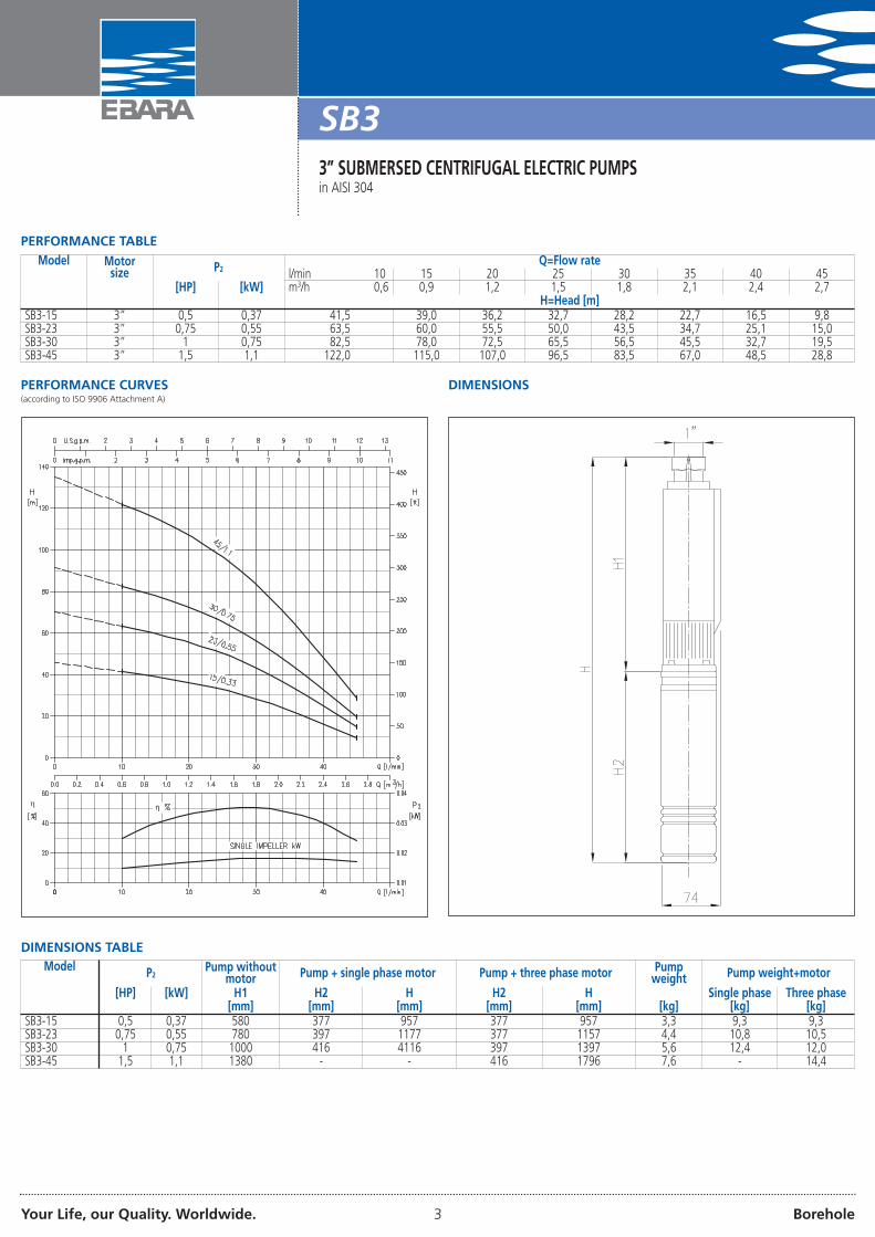
PERFORMANCE TABLEModel Motor
size P2 Q=Flow ratel/min 10 15 20 25 30 35 40 45
[HP] [kW] m3/h 0,6 0,9 1,2 1,5 1,8 2,1 2,4 2,7H=Head [m]
SB3-15 3” 0,5 0,37 41,5 39,0 36,2 32,7 28,2 22,7 16,5 9,8SB3-23 3” 0,75 0,55 63,5 60,0 55,5 50,0 43,5 34,7 25,1 15,0SB3-30 3” 1 0,75 82,5 78,0 72,5 65,5 56,5 45,5 32,7 19,5SB3-45 3” 1,5 1,1 122,0 115,0 107,0 96,5 83,5 67,0 48,5 28,8
PERFORMANCE CURVES(according to ISO 9906 Attachment A)
DIMENSIONS
DIMENSIONS TABLEModel P2 Pump without
motor Pump + single phase motor Pump + three phase motor Pumpweight Pump weight+motor
[HP] [kW] H1 H2 H H2 H Single phase Three phase[mm] [mm] [mm] [mm] [mm] [kg] [kg] [kg]
SB3-15 0,5 0,37 580 377 957 377 957 3,3 9,3 9,3SB3-23 0,75 0,55 780 397 1177 377 1157 4,4 10,8 10,5SB3-30 1 0,75 1000 416 4116 397 1397 5,6 12,4 12,0SB3-45 1,5 1,1 1380 - - 416 1796 7,6 - 14,4

Your Life, our Quality. Worldwide. 4 Borehole
SB33” SUBMERSED CENTRIFUGAL ELECTRIC PUMPSin AISI 304
SECTIONAL VIEW
VERS
ION
WIT
HIN
TERS
TAG
E
MATERIALS TABLERef. Name Material Ref. Name Material2 Valve POM Polyacetalic resin 21 Suction inlet EN 1.4301 (AISI 304)3 O-Ring NBR 22 Screw EN 1.4301 (AISI 304)4 Discharge inlet EN 1.4301 (AISI 304) 23 Filter EN 1.4016 (AISI 430)5 Valve seat PPO mod. + G.F. 24 Shaft EN 1.4105 (AISI 430F)6 Bearing seat PPO mod. + G.F. 25 Spacer PPO mod. + G.F.7 Bearing PUR Polyurethane 26 Joint EN 1.4401 (AISI 316)8 Screw EN 1.4301 (AISI 304) 27 Washer EN 1.4401 (AISI 316)9 Washer EN 1.4301 (AISI 304) 28 Screw EN 1.4301 (AISI 304)10 Washer EN 1.4401 (AISI 316) 29 Nozzle disc POM Polyacetalic resin11 Shaft casing (bearing) EN 1.4401 (AISI 316) 30 Adjuster ring EN 1.4301 (AISI 304)12 Spacer PPO mod. + G.F. 31 Spacer PPO mod. + G.F.13 Nozzle disc POM Polyacetalic resin 32 Shaft casing (bearing) EN 1.4401 (AISI 316)14 Nozzle POM Polyacetalic resin 33 Bearing PUR Polyurethane15 Washer EN 1.4301 (AISI 304) 34 Bearing seat PPO mod. + G.F.16 Impeller PPO mod. + G.F. 35 Spacer PPO mod. + G.F.17 Nozzle disc POM Polyacetalic resin 36 Nozzle disc POM Polyacetalic resin18 External casing EN 1.4301 (AISI 304) 37 Nozzle POM Polyacetalic resin19 Screw EN 1.4301 (AISI 304)
ELECTRIC DATA TABLEModel P2 P1 Voltage IN IA Efficiency Power
factorTs/T Single phase
Capacitor[HP] [kW] [kW] [V] [A] [A] [%] n µF
Single phase0,5 0,37 0,72 230 3,75 8,8 51 0,96 0,58 160,75 0,55 1 230 4,5 12,2 55 0,98 0,54 20
1 0,75 1,31 230 5,85 14,5 57 0,98 0,55 25
Three phase
0,5 0,37 0,72 400 2 8 51 0,71 2,1 -0,75 0,55 0,98 400 2,1 9,1 56 0,75 2 -
1 0,75 1,19 400 2,5 11,7 63 0,75 2 -1,5 1,1 1,75 400 3,2 14 63 0,75 2 -

Your Life, our Quality. Worldwide. 5 Borehole
WINNER 4N4” SUBMERSED CENTRIFUGAL ELECTRIC PUMPSin AISI 304
4” submersed centrifugal electric pumps in AISI 304 with front wearring impeller.
APPLICATIONS• Moving clear water in wells• Pressure boosting of clean water for agricultural, domestic or
industrial use• Irrigation• Moving water in general
TECHNICAL DETAILS• Easy to install• Vertical or horizontal installation
TECHNICAL DATA• Maximum immersion:
- 350 m (with motor in water bath)- 150 m (with motor in bath of liquid refrigerant)
• Maximum temperature of the liquid:- 30°C (with motor in water bath)- 35°C (with motor in bath of liquid refrigerant)
• Maximum presence of sand: 50 ppm• 2 pole motor in bath of liquid refrigerant (OY) or in water bath (WY)• Max start-ups per hour: 30 (OY) - 20 (WY)• Class of insulation F (OY) - B (WY)• Protection rating IP58 (OY) - IP68 (WY)• 230V (+6-10%) 50Hz (OYM), single phase voltage,
three phase 400V (+6-10%) 50Hz (OY)• 230V (± 6%) 50Hz (WYM) single phase voltage, 400V (± 6%) 50Hz
(WY) three phase voltage• G1 ¼ discharge connection for 4N1 - 4N2 - 4N4 models• G2 discharge connection for 4N7 - 4N10 - 4N15 models• For cable dimensioning: see page 41
MATERIALS• External casing, shaft, discharge outlet and valve in AISI 304• Technopolymer impeller and nozzle
CONTROL PANELS• Q Series (see page 42)• 1EPBH (see page 43)
ACCESSORIES (on request)• Presscomfort - Pressure regulator (see page 45)• Press•o•Matic - Variable speed control system (single phase
230V±10% power supply - 220V three phase output - maximummotor power 2.2 kW-3HP) (see page 46)
• 5 litre 10 bar ¾ EPDM vessel• Flat cable 4x2.5 for motor 4” OY - from 10 m, 20 m, 30 m or 40 m• Cable with junction 4x2.5 for motor 4” OY - 40 m• Cable with junction 4x2.5 for motor 4” OY - 60 m• Junction for cable GPS-1 (for 4x1.5 and 4x2.5 cables)• Casting resin cable junction 92A1 (section 1.5÷10 mm2)• PVC 5m key float with counter-weight• PVC 10 m key float with counter-weight• PVC 20 m key float with counter-weight• Capacitor MF 16 450V L=150• Capacitor MF 20,450V L=150• Capacitor MF 25,450V L=150• Capacitor MF 35,450V L=150• Capacitor MF 40,450V L=150• Capacitor MF 50,450V L=150• Capacitor MF 60,450V L=150• Capacitor MF 70,450V L=150• Capacitor MF 80,450V L=150
PERFORMANCE RANGE (according to ISO 9906 Attachment A)
IDENTIFICATION CODE
4 N 4
MOTOR POWER IN KW
- /13 1,1
N° OF IMPELLERS
m3/h AT MAX. EFFICIENCY
MODEL
FOR 4” WELLS
SINGLE PHASE
OY M
TYPE OF MOTOR OYWY
IN BATH OF LIQUID REFRIGERANT
IN WATERBATH
Your Life, our Quality. Worldwide. 6 Borehole
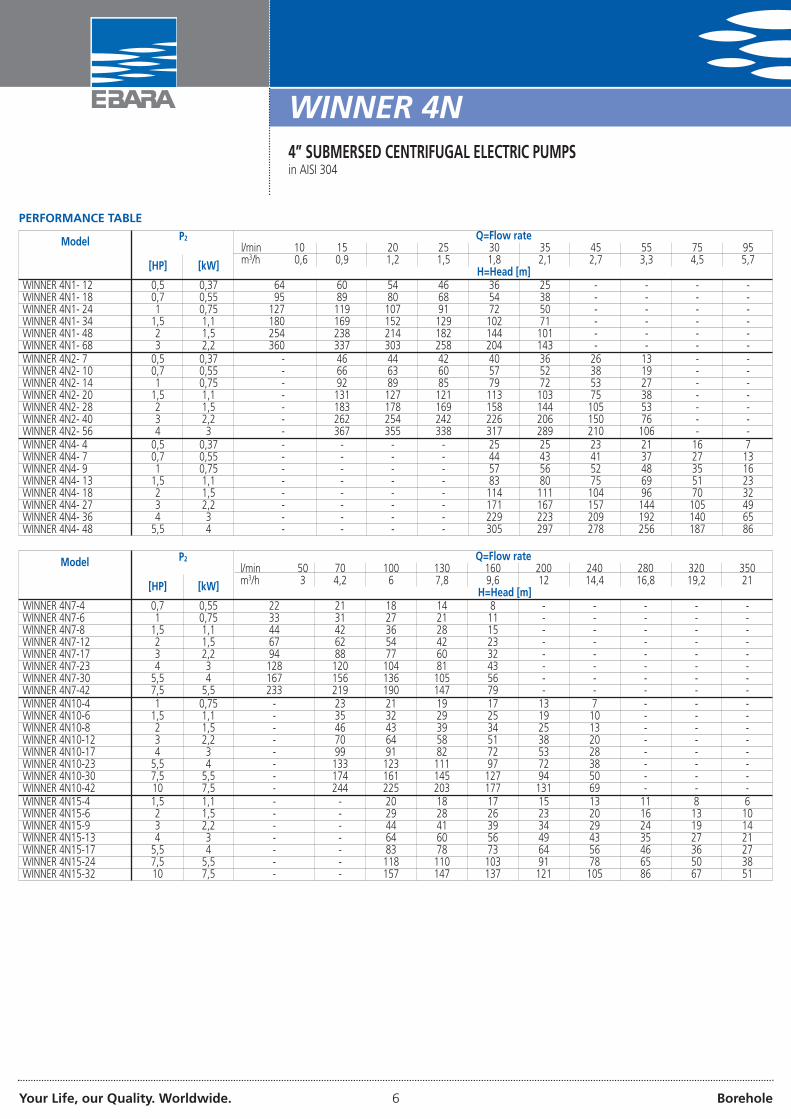
PERFORMANCE TABLE
Model P2 Q=Flow ratel/min 10 15 20 25 30 35 45 55 75 95
[HP] [kW] m3/h 0,6 0,9 1,2 1,5 1,8 2,1 2,7 3,3 4,5 5,7H=Head [m]
WINNER 4N1- 12 0,5 0,37 64 60 54 46 36 25 - - - -WINNER 4N1- 18 0,7 0,55 95 89 80 68 54 38 - - - -WINNER 4N1- 24 1 0,75 127 119 107 91 72 50 - - - -WINNER 4N1- 34 1,5 1,1 180 169 152 129 102 71 - - - -WINNER 4N1- 48 2 1,5 254 238 214 182 144 101 - - - -WINNER 4N1- 68 3 2,2 360 337 303 258 204 143 - - - -WINNER 4N2- 7 0,5 0,37 - 46 44 42 40 36 26 13 - -WINNER 4N2- 10 0,7 0,55 - 66 63 60 57 52 38 19 - -WINNER 4N2- 14 1 0,75 - 92 89 85 79 72 53 27 - -WINNER 4N2- 20 1,5 1,1 - 131 127 121 113 103 75 38 - -WINNER 4N2- 28 2 1,5 - 183 178 169 158 144 105 53 - -WINNER 4N2- 40 3 2,2 - 262 254 242 226 206 150 76 - -WINNER 4N2- 56 4 3 - 367 355 338 317 289 210 106 - -WINNER 4N4- 4 0,5 0,37 - - - - 25 25 23 21 16 7WINNER 4N4- 7 0,7 0,55 - - - - 44 43 41 37 27 13WINNER 4N4- 9 1 0,75 - - - - 57 56 52 48 35 16WINNER 4N4- 13 1,5 1,1 - - - - 83 80 75 69 51 23WINNER 4N4- 18 2 1,5 - - - - 114 111 104 96 70 32WINNER 4N4- 27 3 2,2 - - - - 171 167 157 144 105 49WINNER 4N4- 36 4 3 - - - - 229 223 209 192 140 65WINNER 4N4- 48 5,5 4 - - - - 305 297 278 256 187 86
Model P2 Q=Flow ratel/min 50 70 100 130 160 200 240 280 320 350
[HP] [kW] m3/h 3 4,2 6 7,8 9,6 12 14,4 16,8 19,2 21H=Head [m]
WINNER 4N7-4 0,7 0,55 22 21 18 14 8 - - - - -WINNER 4N7-6 1 0,75 33 31 27 21 11 - - - - -WINNER 4N7-8 1,5 1,1 44 42 36 28 15 - - - - -WINNER 4N7-12 2 1,5 67 62 54 42 23 - - - - -WINNER 4N7-17 3 2,2 94 88 77 60 32 - - - - -WINNER 4N7-23 4 3 128 120 104 81 43 - - - - -WINNER 4N7-30 5,5 4 167 156 136 105 56 - - - - -WINNER 4N7-42 7,5 5,5 233 219 190 147 79 - - - - -WINNER 4N10-4 1 0,75 - 23 21 19 17 13 7 - - -WINNER 4N10-6 1,5 1,1 - 35 32 29 25 19 10 - - -WINNER 4N10-8 2 1,5 - 46 43 39 34 25 13 - - -WINNER 4N10-12 3 2,2 - 70 64 58 51 38 20 - - -WINNER 4N10-17 4 3 - 99 91 82 72 53 28 - - -WINNER 4N10-23 5,5 4 - 133 123 111 97 72 38 - - -WINNER 4N10-30 7,5 5,5 - 174 161 145 127 94 50 - - -WINNER 4N10-42 10 7,5 - 244 225 203 177 131 69 - - -WINNER 4N15-4 1,5 1,1 - - 20 18 17 15 13 11 8 6WINNER 4N15-6 2 1,5 - - 29 28 26 23 20 16 13 10WINNER 4N15-9 3 2,2 - - 44 41 39 34 29 24 19 14WINNER 4N15-13 4 3 - - 64 60 56 49 43 35 27 21WINNER 4N15-17 5,5 4 - - 83 78 73 64 56 46 36 27WINNER 4N15-24 7,5 5,5 - - 118 110 103 91 78 65 50 38WINNER 4N15-32 10 7,5 - - 157 147 137 121 105 86 67 51
WINNER 4N4” SUBMERSED CENTRIFUGAL ELECTRIC PUMPSin AISI 304
Your Life, our Quality. Worldwide. 7 Borehole
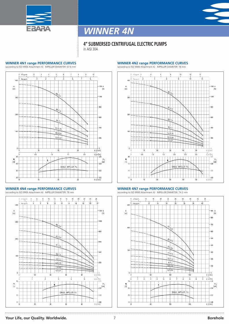
WINNER 4N1 range PERFORMANCE CURVES(according to ISO 9906 Attachment A) IMPELLER DIAMETER: 67.6 mm
WINNER 4N2 range PERFORMANCE CURVES(according to ISO 9906 Attachment A) IMPELLER DIAMETER: 76 mm
WINNER 4N4 range PERFORMANCE CURVES(according to ISO 9906 Attachment A) IMPELLER DIAMETER: 76 mm
WINNER 4N7 range PERFORMANCE CURVES(according to ISO 9906 Attachment A) IMPELLER DIAMETER: 74.2 mm
WINNER 4N4” SUBMERSED CENTRIFUGAL ELECTRIC PUMPSin AISI 304

Your Life, our Quality. Worldwide. 8 Borehole
DIMENSIONS
WINNER 4N10 range PERFORMANCE CURVES(according to ISO 9906 Attachment A) IMPELLER DIAMETER: 72 mm
1
WINNER 4N15 range PERFORMANCE CURVES(according to ISO 9906 Attachment A) IMPELLER DIAMETER: 75.5 mm
WINNER 4N4” SUBMERSED CENTRIFUGAL ELECTRIC PUMPSin AISI 304
Your Life, our Quality. Worldwide. 9 Borehole
DIMENSIONS TABLE
WINNER 4N4” SUBMERSED CENTRIFUGAL ELECTRIC PUMPSin AISI 304
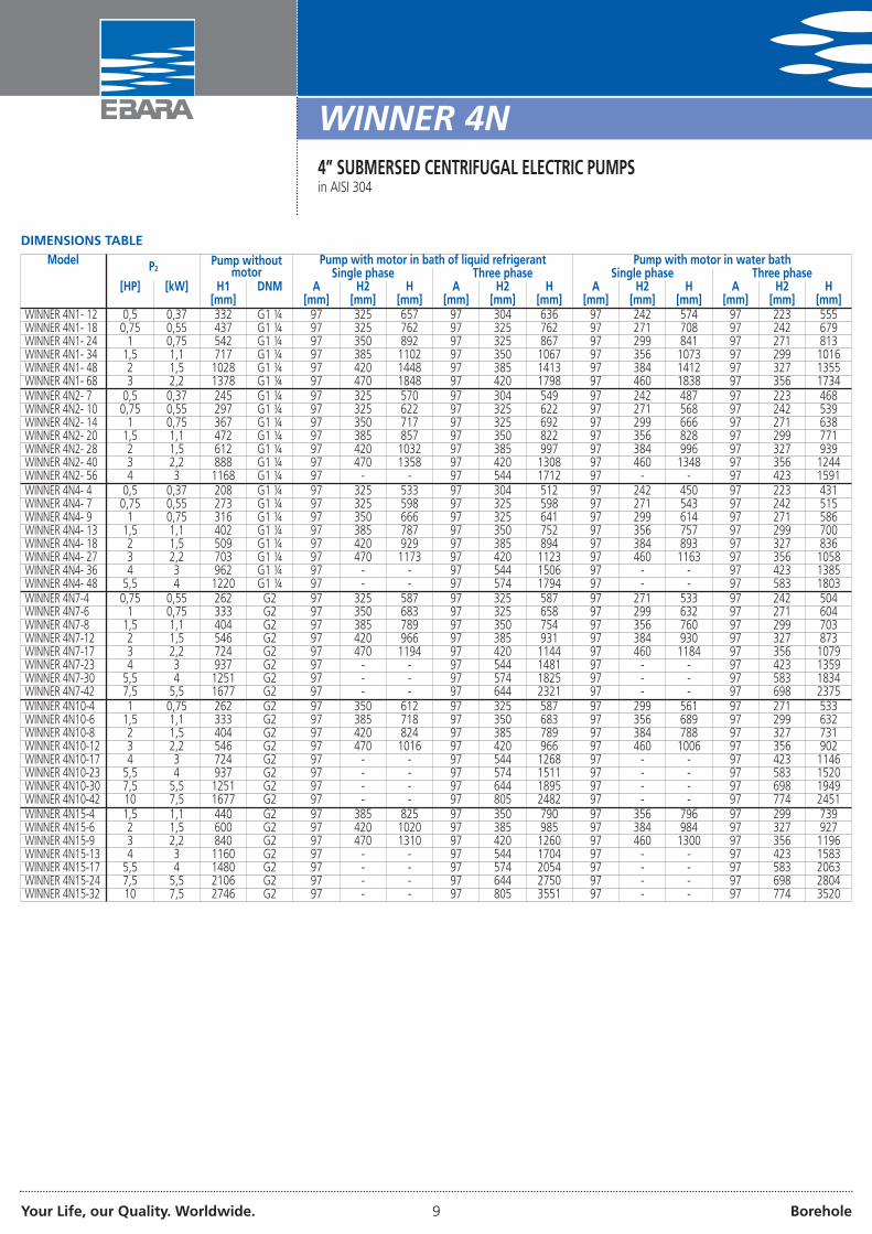
Model P2 Pump withoutmotor
Pump with motor in bath of liquid refrigerant Pump with motor in water bathSingle phase Three phase Single phase Three phase
[HP] [kW] H1 DNM A H2 H A H2 H A H2 H A H2 H[mm] [mm] [mm] [mm] [mm] [mm] [mm] [mm] [mm] [mm] [mm] [mm] [mm]
WINNER 4N1- 12 0,5 0,37 332 G1 ¼ 97 325 657 97 304 636 97 242 574 97 223 555WINNER 4N1- 18 0,75 0,55 437 G1 ¼ 97 325 762 97 325 762 97 271 708 97 242 679WINNER 4N1- 24 1 0,75 542 G1 ¼ 97 350 892 97 325 867 97 299 841 97 271 813WINNER 4N1- 34 1,5 1,1 717 G1 ¼ 97 385 1102 97 350 1067 97 356 1073 97 299 1016WINNER 4N1- 48 2 1,5 1028 G1 ¼ 97 420 1448 97 385 1413 97 384 1412 97 327 1355WINNER 4N1- 68 3 2,2 1378 G1 ¼ 97 470 1848 97 420 1798 97 460 1838 97 356 1734WINNER 4N2- 7 0,5 0,37 245 G1 ¼ 97 325 570 97 304 549 97 242 487 97 223 468WINNER 4N2- 10 0,75 0,55 297 G1 ¼ 97 325 622 97 325 622 97 271 568 97 242 539WINNER 4N2- 14 1 0,75 367 G1 ¼ 97 350 717 97 325 692 97 299 666 97 271 638WINNER 4N2- 20 1,5 1,1 472 G1 ¼ 97 385 857 97 350 822 97 356 828 97 299 771WINNER 4N2- 28 2 1,5 612 G1 ¼ 97 420 1032 97 385 997 97 384 996 97 327 939WINNER 4N2- 40 3 2,2 888 G1 ¼ 97 470 1358 97 420 1308 97 460 1348 97 356 1244WINNER 4N2- 56 4 3 1168 G1 ¼ 97 - - 97 544 1712 97 - - 97 423 1591WINNER 4N4- 4 0,5 0,37 208 G1 ¼ 97 325 533 97 304 512 97 242 450 97 223 431WINNER 4N4- 7 0,75 0,55 273 G1 ¼ 97 325 598 97 325 598 97 271 543 97 242 515WINNER 4N4- 9 1 0,75 316 G1 ¼ 97 350 666 97 325 641 97 299 614 97 271 586WINNER 4N4- 13 1,5 1,1 402 G1 ¼ 97 385 787 97 350 752 97 356 757 97 299 700WINNER 4N4- 18 2 1,5 509 G1 ¼ 97 420 929 97 385 894 97 384 893 97 327 836WINNER 4N4- 27 3 2,2 703 G1 ¼ 97 470 1173 97 420 1123 97 460 1163 97 356 1058WINNER 4N4- 36 4 3 962 G1 ¼ 97 - - 97 544 1506 97 - - 97 423 1385WINNER 4N4- 48 5,5 4 1220 G1 ¼ 97 - - 97 574 1794 97 - - 97 583 1803WINNER 4N7-4 0,75 0,55 262 G2 97 325 587 97 325 587 97 271 533 97 242 504WINNER 4N7-6 1 0,75 333 G2 97 350 683 97 325 658 97 299 632 97 271 604WINNER 4N7-8 1,5 1,1 404 G2 97 385 789 97 350 754 97 356 760 97 299 703WINNER 4N7-12 2 1,5 546 G2 97 420 966 97 385 931 97 384 930 97 327 873WINNER 4N7-17 3 2,2 724 G2 97 470 1194 97 420 1144 97 460 1184 97 356 1079WINNER 4N7-23 4 3 937 G2 97 - - 97 544 1481 97 - - 97 423 1359WINNER 4N7-30 5,5 4 1251 G2 97 - - 97 574 1825 97 - - 97 583 1834WINNER 4N7-42 7,5 5,5 1677 G2 97 - - 97 644 2321 97 - - 97 698 2375WINNER 4N10-4 1 0,75 262 G2 97 350 612 97 325 587 97 299 561 97 271 533WINNER 4N10-6 1,5 1,1 333 G2 97 385 718 97 350 683 97 356 689 97 299 632WINNER 4N10-8 2 1,5 404 G2 97 420 824 97 385 789 97 384 788 97 327 731WINNER 4N10-12 3 2,2 546 G2 97 470 1016 97 420 966 97 460 1006 97 356 902WINNER 4N10-17 4 3 724 G2 97 - - 97 544 1268 97 - - 97 423 1146WINNER 4N10-23 5,5 4 937 G2 97 - - 97 574 1511 97 - - 97 583 1520WINNER 4N10-30 7,5 5,5 1251 G2 97 - - 97 644 1895 97 - - 97 698 1949WINNER 4N10-42 10 7,5 1677 G2 97 - - 97 805 2482 97 - - 97 774 2451WINNER 4N15-4 1,5 1,1 440 G2 97 385 825 97 350 790 97 356 796 97 299 739WINNER 4N15-6 2 1,5 600 G2 97 420 1020 97 385 985 97 384 984 97 327 927WINNER 4N15-9 3 2,2 840 G2 97 470 1310 97 420 1260 97 460 1300 97 356 1196WINNER 4N15-13 4 3 1160 G2 97 - - 97 544 1704 97 - - 97 423 1583WINNER 4N15-17 5,5 4 1480 G2 97 - - 97 574 2054 97 - - 97 583 2063WINNER 4N15-24 7,5 5,5 2106 G2 97 - - 97 644 2750 97 - - 97 698 2804WINNER 4N15-32 10 7,5 2746 G2 97 - - 97 805 3551 97 - - 97 774 3520
Your Life, our Quality. Worldwide. 10 Borehole
WINNER 4N4” SUBMERSED CENTRIFUGAL ELECTRIC PUMPSin AISI 304
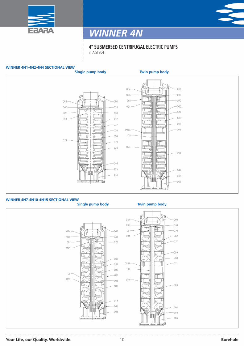
WINNER 4N1-4N2-4N4 SECTIONAL VIEWSingle pump body Twin pump body
WINNER 4N7-4N10-4N15 SECTIONAL VIEWSingle pump body Twin pump body
Your Life, our Quality. Worldwide. 11 Borehole
WINNER 4N4” SUBMERSED CENTRIFUGAL ELECTRIC PUMPSin AISI 304
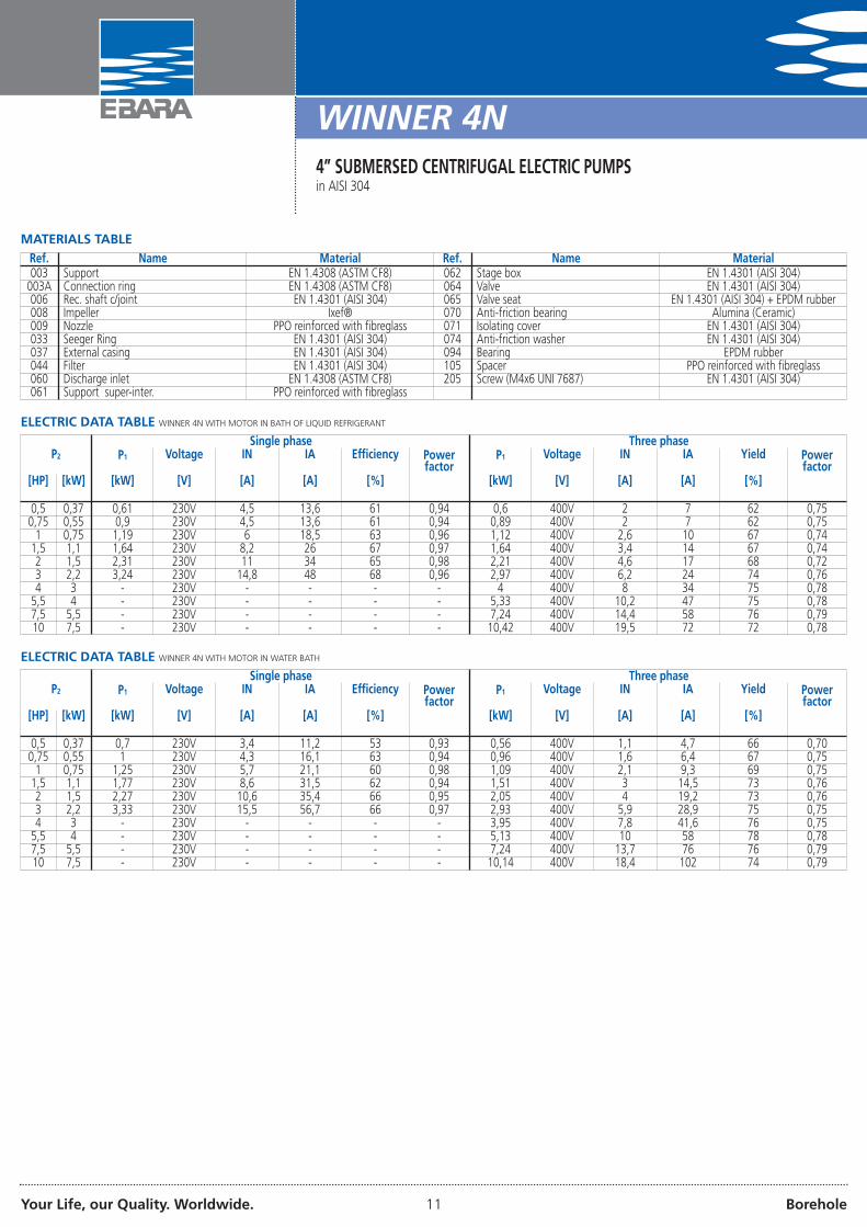
MATERIALS TABLERef. Name Material Ref. Name Material003 Support EN 1.4308 (ASTM CF8) 062 Stage box EN 1.4301 (AISI 304)
003A Connection ring EN 1.4308 (ASTM CF8) 064 Valve EN 1.4301 (AISI 304)006 Rec. shaft c/joint EN 1.4301 (AISI 304) 065 Valve seat EN 1.4301 (AISI 304) + EPDM rubber008 Impeller Ixef® 070 Anti-friction bearing Alumina (Ceramic)009 Nozzle PPO reinforced with fibreglass 071 Isolating cover EN 1.4301 (AISI 304)033 Seeger Ring EN 1.4301 (AISI 304) 074 Anti-friction washer EN 1.4301 (AISI 304)037 External casing EN 1.4301 (AISI 304) 094 Bearing EPDM rubber044 Filter EN 1.4301 (AISI 304) 105 Spacer PPO reinforced with fibreglass060 Discharge inlet EN 1.4308 (ASTM CF8) 205 Screw (M4x6 UNI 7687) EN 1.4301 (AISI 304)061 Support super-inter. PPO reinforced with fibreglass
ELECTRIC DATA TABLE WINNER 4N WITH MOTOR IN BATH OF LIQUID REFRIGERANT
P2Single phase Three phase
P1 Voltage IN IA Efficiency Powerfactor
P1 Voltage IN IA Yield Powerfactor
[HP] [kW] [kW] [V] [A] [A] [%] [kW] [V] [A] [A] [%]
0,5 0,37 0,61 230V 4,5 13,6 61 0,94 0,6 400V 2 7 62 0,750,75 0,55 0,9 230V 4,5 13,6 61 0,94 0,89 400V 2 7 62 0,75
1 0,75 1,19 230V 6 18,5 63 0,96 1,12 400V 2,6 10 67 0,741,5 1,1 1,64 230V 8,2 26 67 0,97 1,64 400V 3,4 14 67 0,742 1,5 2,31 230V 11 34 65 0,98 2,21 400V 4,6 17 68 0,723 2,2 3,24 230V 14,8 48 68 0,96 2,97 400V 6,2 24 74 0,764 3 - 230V - - - - 4 400V 8 34 75 0,78
5,5 4 - 230V - - - - 5,33 400V 10,2 47 75 0,787,5 5,5 - 230V - - - - 7,24 400V 14,4 58 76 0,7910 7,5 - 230V - - - - 10,42 400V 19,5 72 72 0,78
ELECTRIC DATA TABLE WINNER 4N WITH MOTOR IN WATER BATH
P2Single phase Three phase
P1 Voltage IN IA Efficiency Powerfactor
P1 Voltage IN IA Yield Powerfactor
[HP] [kW] [kW] [V] [A] [A] [%] [kW] [V] [A] [A] [%]
0,5 0,37 0,7 230V 3,4 11,2 53 0,93 0,56 400V 1,1 4,7 66 0,700,75 0,55 1 230V 4,3 16,1 63 0,94 0,96 400V 1,6 6,4 67 0,75
1 0,75 1,25 230V 5,7 21,1 60 0,98 1,09 400V 2,1 9,3 69 0,751,5 1,1 1,77 230V 8,6 31,5 62 0,94 1,51 400V 3 14,5 73 0,762 1,5 2,27 230V 10,6 35,4 66 0,95 2,05 400V 4 19,2 73 0,763 2,2 3,33 230V 15,5 56,7 66 0,97 2,93 400V 5,9 28,9 75 0,754 3 - 230V - - - - 3,95 400V 7,8 41,6 76 0,75
5,5 4 - 230V - - - - 5,13 400V 10 58 78 0,787,5 5,5 - 230V - - - - 7,24 400V 13,7 76 76 0,7910 7,5 - 230V - - - - 10,14 400V 18,4 102 74 0,79
Your Life, our Quality. Worldwide. 12 Borehole
4BHS4” SUBMERSED CENTRIFUGAL PUMPSin AISI 304
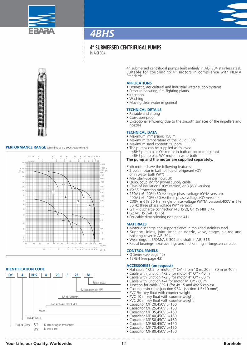
4” submersed centrifugal pumps built entirely in AISI 304 stainless steel.Suitable for coupling to 4" motors in compliance with NEMAStandards.
APPLICATIONS• Domestic, agricultural and industrial water supply systems• Pressure boosting, fire-fighting plants• Irrigation• Washing• Moving clear water in general
TECHNICAL DETAILS• Reliable and strong• Corrosion-proof• Exceptional efficiency due to the smooth surfaces of the impellers and
nozzles
TECHNICAL DATA• Maximum immersion: 150 m• Maximum temperature of the liquid: 30°C• Maximum sand content: 50 ppm• The pumps can be supplied as follows:
- 4BHS pump plus OY motor in bath of liquid refrigerant- 4BHS pump plus WY motor in waterbathThe pump and the motor are supplied separately.
Both motors have the following features:• 2 pole motor in bath of liquid refrigerant (OY)
or in water bath (WY)• Max start-ups per hour: 30• Quick coupling for power supply cable• Class of insulation F (OY version) or B (WY version)• IPX58 Protection rating• 230V (+6 -10%) 50 Hz single phase voltage (OYM version),
400V (+6 -10%) 50 Hz three phase voltage (OY version)• 230V ± 6% 50 Hz single phase voltage (WYM version),400V ± 6%
50 Hz three phase voltage (WY version)• G1 ¼ discharge connection (4BHS 2), G1 ½ (4BHS 4),• G2 (4BHS 7-4BHS 15)• For cable dimensioning (see page 41)
MATERIALS• Motor discharge and support sleeve in moulded stainless steel• Support, inlets, joint, impeller, nozzle, valve, stages, tie-rod and
isolating cover in AISI 304• Wear rings in EPDM/AISI 304 and shaft in AISI 316• Radial bearings, axial bearings and friction ring in tungsten carbide
CONTROL PANELS• Q Series (see page 42)• 1EPBH (see page 43)
ACCESSORIES (on request)• Flat cable 4x2.5 for motor 4” OY - from 10 m, 20 m, 30 m or 40 m• Cable with junction 4x2.5 for motor 4” OY - 40 m• Cable with junction 4x2.5 for motor 4” OY - 60 m• Cable with junction 4x4 for motor 4” OY - 60 m• Junction for cable GPS-1 (for 4x1.5 and 4x2.5 cables)• Casting resin cable junction 92A1 (section 1.5÷10 mm2)• PVC 5m key float with counter-weight• PVC 10 m key float with counter-weight• PVC 20 m key float with counter-weight• Capacitor MF 20,450V L=150• Capacitor MF 25,450V L=150• Capacitor MF 35,450V L=150• Capacitor MF 40,450V L=150• Capacitor MF 50,450V L=150• Capacitor MF 60,450V L=150• Capacitor MF 70,450V L=150• Capacitor MF 80,450V L=150
PERFORMANCE RANGE (according to ISO 9906 Attachment A)
IDENTIFICATION CODE
BHS 4 29
SINGLE PHASE
/ 22 M
MOTOR POWER IN KW
N° OF IMPELLERS
m3/h AT MAX. EFFICIENCY
MODEL
FOR 4” WELLS
OY 4
TYPE OF MOTOR OYWY
IN BATH OF LIQUID REFRIGERANT
IN WATER BATH

Your Life, our Quality. Worldwide. 13 Borehole
4BHS4” SUBMERSED CENTRIFUGAL PUMPSin AISI 304
4BHS 2 range PERFORMANCE CURVES(according to ISO 9906 Attachment A) IMPELLER DIAMETER: 70.5 mm
4BHS 4 range PERFORMANCE CURVES(according to ISO 9906 Attachment A) IMPELLER DIAMETER: 72 mm
4BHS 7 range PERFORMANCE CURVES(according to ISO 9906 Attachment A) IMPELLER DIAMETER: 74 mm
4BHS 15 range PERFORMANCE CURVES(according to ISO 9906 Attachment A) IMPELLER DIAMETER: 72 mm

Your Life, our Quality. Worldwide. 14 Borehole
4BHS4” SUBMERSED CENTRIFUGAL PUMPSin AISI 304
PERFORMANCE TABLEModel P2 Q=Flow rate
l/min 15 20 30 40 50 60 80 100 120 150 180 220 260 300Single phase Three phase [HP] [kW] m3/h 0,9 1,2 1,8 2,4 3 3,6 4,8 6 7,2 9 10,8 13,2 15,6 18
H=Head [m]4BHS2 13/5M 4BHS2 13/5 0,75 0,55 66,5 62,5 53,5 42,5 28,6 - - - - - - - - -4BHS2 18/7M 4BHS2 18/7 1,0 0,75 92,0 86,0 74,0 58,5 39,6 - - - - - - - - -4BHS2 27/11M 4BHS2 27/11 1,5 1,1 138,0 129,0 111,0 88,0 59,5 - - - - - - - - -4BHS2 36/15M 4BHS2 36/15 2,0 1,5 184,0 172,0 148,0 117,0 79,0 - - - - - - - - -4BHS2 44/22M 4BHS2 44/22 3,0 2,2 224,0 211,0 180,0 143,0 97,0 - - - - - - - - -4BHS2 51/22M 4BHS2 51/22 3,0 2,2 260,0 244,0 209,0 166,0 112,0 - - - - - - - - -4BHS4 7/5M 4BHS4 7/5 0,75 0,55 - - 37,5 35,8 34,2 31,8 24,4 14,7 - - - - - -4BHS4 10/7M 4BHS4 10/7 1,0 0,75 - - 53,5 51,0 49,0 45,5 34,9 21,0 - - - - - -4BHS4 15/11M 4BHS4 15/11 1,5 1,1 - - 80,5 77,0 73,0 68,0 52,5 31,5 - - - - - -4BHS4 20/15M 4BHS4 20/15 2,0 1,5 - - 107,0 102,0 97,5 91,0 70,0 42,0 - - - - - -4BHS4 24/22M 4BHS4 24/22 3,0 2,2 - - 128,0 123,0 117,0 109,0 84,0 50,5 - - - - - -4BHS4 29/22M 4BHS4 29/22 3,0 2,2 - - 155,0 148,0 142,0 132,0 101,0 61,0 - - - - - -
4BHS4 36/30 4,0 3,0 - - 193,0 184,0 176,0 163,0 126,0 75,5 - - - - - -4BHS4 48/40 5,5 4,0 - - 257,0 246,0 234,0 218,0 168,0 101,0 - - - - - -
4BHS7 4/7M 4BHS7 4/7 1,0 0,75 - - - - - 22,8 22,0 20,8 19,1 15,7 10,4 - - -4BHS7 7/11M 4BHS7 7/11 1,5 1,1 - - - - - 39,9 38,5 36,3 33,5 27,5 18,2 - - -4BHS7 10/15M 4BHS7 10/15 2,0 1,5 - - - - - 57,0 55,0 52,0 48,0 39,3 26,0 - - -4BHS7 12/22M 4BHS7 12/22 3,0 2,2 - - - - - 68,5 66,0 62,5 57,5 47,0 31,3 - - -4BHS7 14/22M 4BHS7 14/22 3,0 2,2 - - - - - 80,0 77,0 72,5 67,0 55,0 36,5 - - -
4BHS7 18/30 4,0 3,0 - - - - - 106,0 102,0 97,5 91,0 75,5 52,0 - - -4BHS7 23/40 5,5 4,0 - - - - - 135,0 131,0 125,0 116,0 96,5 66,0 - - -
4BHS15 7/15M 4BHS15 7/15 2,0 1,5 - - - - - - - 30,5 29,3 27,7 25,6 21,5 16,0 9,14BHS15 10/22M 4BHS15 10/22 3,0 2,2 - - - - - - - 43,5 42,0 39,5 36,6 30,7 22,9 13,0
4BHS15 13/30 4,0 3,0 - - - - - - - 59,0 57,5 54,5 50,5 43,5 34,1 22,14BHS15 17/40 5,5 4,0 - - - - - - - 77,0 75,0 71,0 66,0 57,0 44,5 28,94BHS15 25/55 7,5 5,5 - - - - - - - 114,0 110,0 105,0 97,0 83,5 65,5 42,5
DIMENSIONS
Your Life, our Quality. Worldwide. 15 Borehole
4BHS4” SUBMERSED CENTRIFUGAL PUMPSin AISI 304
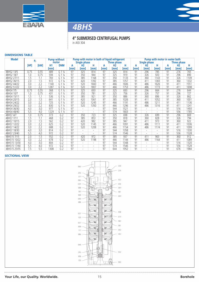
DIMENSIONS TABLEModel P2 Pump without
motorPump with motor in bath of liquid refrigerant Pump with motor in water bathSingle phase Three phase Single phase Three phase
[HP] [kW] H1 DNM A H2 H A H2 H A H2 H A H2 H[mm] [mm] [mm] [mm] [mm] [mm] [mm] [mm] [mm] [mm] [mm] [mm] [mm]
4BHS2 13/5 0,75 0,55 489 G 1 ¼ 97 325 814 97 325 814 91 296 785 91 276 7654BHS2 18/7 1,0 0,75 594 G 1 ¼ 97 350 944 97 325 919 91 326 920 91 296 8904BHS2 27/11 1,5 1,1 783 G 1 ¼ 97 385 1168 97 350 1133 91 360 1143 91 326 11094BHS2 36/15 2,0 1,5 972 G 1 ¼ 97 420 1392 97 385 1357 91 411 1383 91 360 13324BHS2 44/22 3,0 2,2 1140 G 1 ¼ 97 520 1660 97 466 1606 91 486 1626 91 411 15514BHS2 51/22 3,0 2,2 1287 G 1 ¼ 97 520 1807 97 466 1753 91 486 1773 91 411 16984BHS4 7/5 0,75 0,55 368 G 1 ½ 97 325 693 97 325 693 91 296 664 91 276 6444BHS4 10/7 1,0 0,75 431 G 1 ½ 97 350 781 97 325 756 91 326 757 91 296 7274BHS4 15/11 1,5 1,1 536 G 1 ½ 97 385 921 97 350 886 91 360 896 91 326 8624BHS4 20/15 2,0 1,5 641 G 1 ½ 97 420 1061 97 385 1026 91 411 1052 91 360 10014BHS4 24/22 3,0 2,2 725 G 1 ½ 97 520 1245 97 466 1191 91 486 1211 91 411 11364BHS4 29/22 3,0 2,2 830 G 1 ½ 97 520 1350 97 466 1296 91 486 1316 91 411 12414BHS4 36/30 4,0 3,0 977 G 1 ½ 97 - - 97 544 1521 91 - - 91 516 14934BHS4 48/40 5,5 4,0 1229 G 1 ½ 97 - - 97 574 1803 91 - - 91 556 17854BHS7 4/7 1,0 0,75 373 G 2 97 350 723 97 325 698 91 326 699 91 296 6694BHS7 7/11 1,5 1,1 468 G 2 97 385 853 97 350 818 91 360 828 91 326 7944BHS7 10/15 2,0 1,5 562 G 2 97 420 982 97 385 947 91 411 973 91 360 9224BHS7 12/22 3,0 2,2 625 G 2 97 520 1145 97 466 1091 91 486 1111 91 411 10364BHS7 14/22 3,0 2,2 688 G 2 97 520 1208 97 466 1154 91 486 1174 91 411 10994BHS7 18/30 4,0 3,0 814 G 2 97 - - 97 544 1358 91 - - 91 516 13304BHS7 23/40 5,5 4,0 972 G 2 97 - - 97 574 1546 91 - - 91 556 15284BHS15 7/15 2,0 1,5 552 G 2 97 420 972 97 385 937 91 411 963 91 360 9124BHS15 10/22 3,0 2,2 678 G 2 97 520 1198 97 466 1144 91 486 1164 91 411 10894BHS15 13/30 4,0 3,0 804 G 2 97 - - 97 544 1348 91 - - 91 516 13204BHS15 17/40 5,5 4,0 972 G 2 97 - - 97 574 1546 91 - - 91 556 15284BHS15 25/55 7,5 5,5 1308 G 2 97 - - 97 644 1952 91 - - 91 676 1984
SECTIONAL VIEW

Your Life, our Quality. Worldwide. 16 Borehole
MATERIALS TABLERef. Name Material Ref. Name Material003 Lower support EN 1.4301 (AISI 304) 068 Spacer EN 1.4301 (AISI 304)006 Complete shaft EN 1.4401 (AISI 316) 069 Shaft casing Tungsten Carbide007 Impeller EN 1.4301 (AISI 304) 071 Isolating cover EN 1.4301 (AISI 304)022 Tie-rod EN 1.4301 (AISI 304) 073 Wear ring EN 1.4301 (AISI 304) + EPDM026 O-Ring NBR 086 Spacer EN 1.4301 (AISI 304)028 O-Ring NBR 089 Shaft washer EN 1.4301 (AISI 304)032 Key EN 1.4401 (AISI 316) 091 Spacer EN 1.4301 (AISI 304)034 Impeller nut EN 1.4301 (AISI 304) 093 Axial bearing Tungsten Carbide050 Bearing washer EN 1.4301 (AISI 304) 094 Radial bearing Tungsten Carbide057 Spacer EN 1.4301 (AISI 304) 105 Spacer EN 1.4301 (AISI 304)060 Discharge inlet EN 1.4301 (AISI 304) 117 Anti-friction washer Tungsten Carbide061 Support stage EN 1.4301 (AISI 304) 130 Joint EN 1.4301 (AISI 304)062 Intermediate stage EN 1.4301 (AISI 304) 205 Screw EN 1.4301 (AISI 304)063 Suction stage EN 1.4301 (AISI 304) 220 Nut EN 1.4301 (AISI 304)064 Valve seat EN 1.4301 (AISI 304) + NBR 235 Washer grower EN 1.4301 (AISI 304)065 Valve EN 1.4301 (AISI 304) 245 Set of screws EN 1.4301 (AISI 304)
4BHS4” SUBMERSED CENTRIFUGAL PUMPSin AISI 304
ELECTRIC DATA TABLE 4BHS WITH MOTOR IN BATH OF LIQUID REFRIGERANT
P2Single phase Three phase
P1 Voltage IN IA Efficiency Powerfactor
P1 Voltage IN IA Efficiency Powerfactor
[HP] [kW] [kW] [V] [A] [A] [%] [kW] [V] [A] [A] [%]
0,75 0,55 0,90 230V 4,5 13,6 61 0,94 0,89 400V 2 7 62 0,751 0,75 0,19 230V 6 18,5 63 0,96 1,12 400V 2,6 10 67 0,74
1,5 1,1 1,64 230V 8,2 26 67 0,97 1,64 400V 3,4 14 67 0,742 1,5 2,31 230V 11 34 65 0,98 2,21 400V 4,6 17 68 0,723 2,2 3,24 230V 14,8 48 68 0,96 2,97 400V 6,2 24 74 0,764 3 - 230V - - - - 4,00 400V 8 34 75 0,78
5,5 4 - 230V - - - - 5,33 400V 10,2 47 75 0,787,5 5,5 - 230V - - - - 7,24 400V 14,4 58 76 0,79
ELECTRIC DATA TABLE 4BHS WITH MOTOR IN WATERBATH
P2Single phase Three phase
P1 Voltage I IA Efficiency Powerfactor
P1 Voltage IN IA Efficiency Powerfactor
[HP] [kW] [kW] [V] [A] [A] [%] [kW] [V] [A] [A] [%]
0,75 0,55 1,00 230V 4,8 13,4 55 0,92 0,96 400V 1,9 7,7 57 0,761 0,75 1,21 230V 5,6 17,1 62 0,99 1,25 400V 2,4 11,2 60 0,77
1,5 1,1 1,90 230V 9,7 30,1 58 0,94 1,62 400V 3,2 15,8 68 0,772 1,5 2,38 230V 12 38,5 63 0,96 2,31 400V 4,3 21,3 65 0,803 2,2 3,33 230V 16,6 55,6 66 0,97 2,93 400V 5,8 32,8 75 0,744 3 - 230V - - - - 4,05 400V 7,7 44,5 74 0,77
5,5 4 - 230V - - - - 5,33 400V 10,1 51 75 0,777,5 5,5 - 230V - - - - 7,64 400V 13,8 66,9 72 0,80
Your Life, our Quality. Worldwide. 17 Borehole
IDROGO5” SUBMERSED CENTRIFUGAL ELECTRIC PUMPSin AISI 304
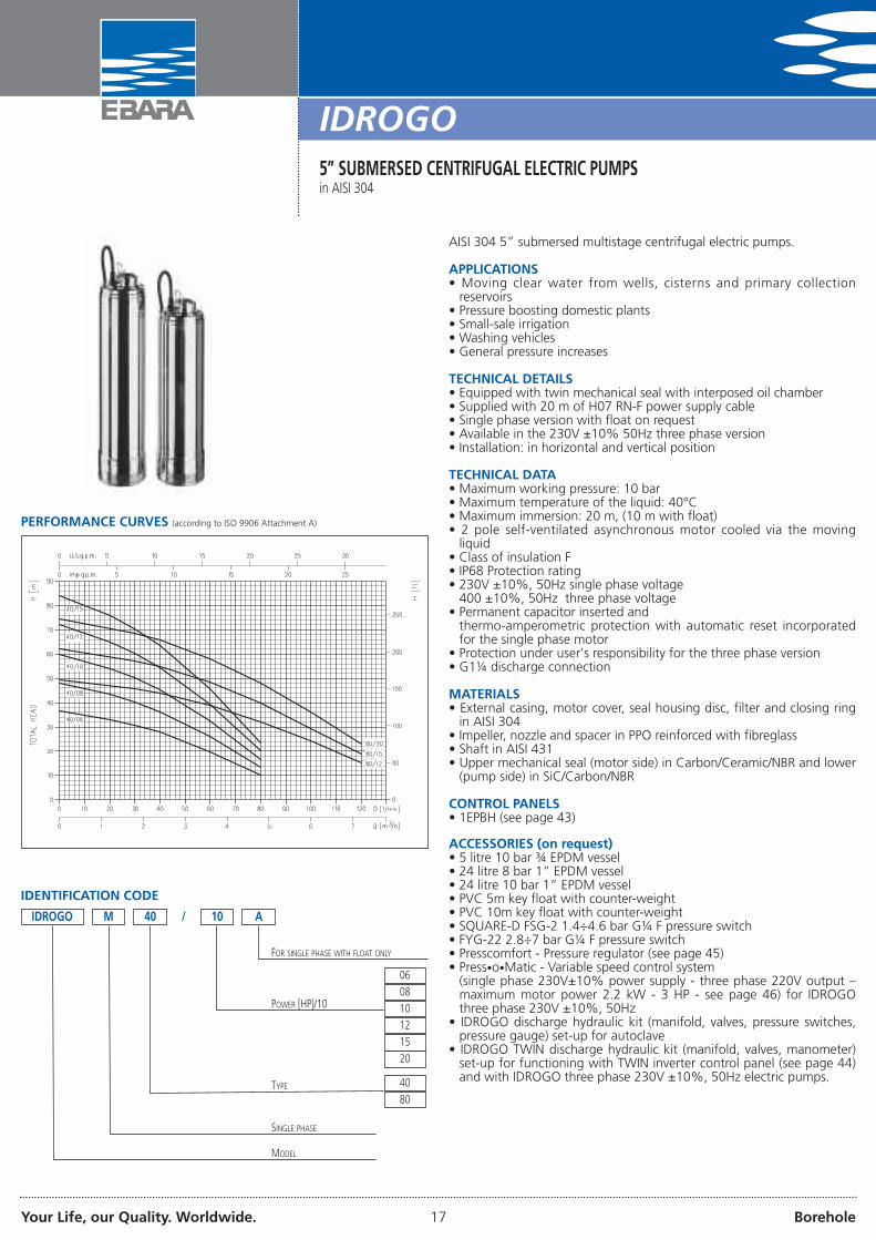
AISI 304 5” submersed multistage centrifugal electric pumps.
APPLICATIONS• Moving clear water from wells, cisterns and primary collection
reservoirs• Pressure boosting domestic plants• Small-sale irrigation• Washing vehicles• General pressure increases
TECHNICAL DETAILS• Equipped with twin mechanical seal with interposed oil chamber• Supplied with 20 m of H07 RN-F power supply cable• Single phase version with float on request• Available in the 230V ±10% 50Hz three phase version• Installation: in horizontal and vertical position
TECHNICAL DATA• Maximum working pressure: 10 bar• Maximum temperature of the liquid: 40°C• Maximum immersion: 20 m, (10 m with float)• 2 pole self-ventilated asynchronous motor cooled via the moving
liquid• Class of insulation F• IP68 Protection rating• 230V ±10%, 50Hz single phase voltage
400 ±10%, 50Hz three phase voltage• Permanent capacitor inserted and
thermo-amperometric protection with automatic reset incorporatedfor the single phase motor
• Protection under user's responsibility for the three phase version• G1¼ discharge connection
MATERIALS• External casing, motor cover, seal housing disc, filter and closing ring
in AISI 304• Impeller, nozzle and spacer in PPO reinforced with fibreglass• Shaft in AISI 431• Upper mechanical seal (motor side) in Carbon/Ceramic/NBR and lower
(pump side) in SiC/Carbon/NBR
CONTROL PANELS• 1EPBH (see page 43)
ACCESSORIES (on request)• 5 litre 10 bar ¾ EPDM vessel• 24 litre 8 bar 1” EPDM vessel• 24 litre 10 bar 1” EPDM vessel• PVC 5m key float with counter-weight• PVC 10m key float with counter-weight• SQUARE-D FSG-2 1.4÷4.6 bar G¼ F pressure switch• FYG-22 2.8÷7 bar G¼ F pressure switch• Presscomfort - Pressure regulator (see page 45)• Press•o•Matic - Variable speed control system
(single phase 230V±10% power supply - three phase 220V output –maximum motor power 2.2 kW - 3 HP - see page 46) for IDROGOthree phase 230V ±10%, 50Hz
• IDROGO discharge hydraulic kit (manifold, valves, pressure switches,pressure gauge) set-up for autoclave
• IDROGO TWIN discharge hydraulic kit (manifold, valves, manometer)set-up for functioning with TWIN inverter control panel (see page 44)and with IDROGO three phase 230V ±10%, 50Hz electric pumps.
PERFORMANCE CURVES (according to ISO 9906 Attachment A)
IDENTIFICATION CODE
IDROGO M
TYPE
POWER [HP]/10
MODEL
40
06
/ 10
40
80
SINGLE PHASE
08
10
12
15
A
FOR SINGLE PHASE WITH FLOAT ONLY
20
Your Life, our Quality. Worldwide. 18 Borehole
IDROGO5” SUBMERSED CENTRIFUGAL ELECTRIC PUMPSin AISI 304
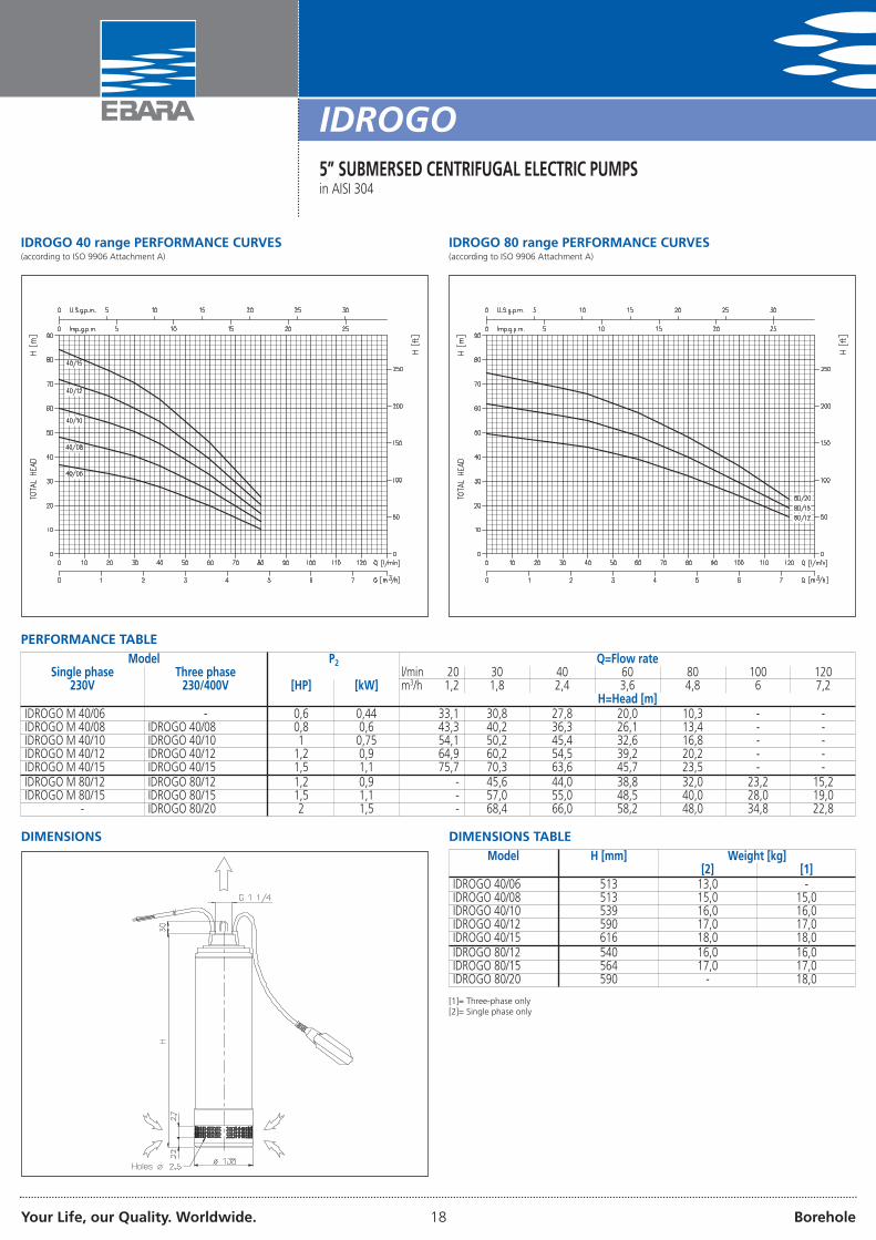
IDROGO 40 range PERFORMANCE CURVES(according to ISO 9906 Attachment A)
IDROGO 80 range PERFORMANCE CURVES(according to ISO 9906 Attachment A)
PERFORMANCE TABLEModel P2 Q=Flow rate
Single phase Three phase l/min 20 30 40 60 80 100 120230V 230/400V [HP] [kW] m3/h 1,2 1,8 2,4 3,6 4,8 6 7,2
H=Head [m]IDROGO M 40/06 - 0,6 0,44 33,1 30,8 27,8 20,0 10,3 - -IDROGO M 40/08 IDROGO 40/08 0,8 0,6 43,3 40,2 36,3 26,1 13,4 - -IDROGO M 40/10 IDROGO 40/10 1 0,75 54,1 50,2 45,4 32,6 16,8 - -IDROGO M 40/12 IDROGO 40/12 1,2 0,9 64,9 60,2 54,5 39,2 20,2 - -IDROGO M 40/15 IDROGO 40/15 1,5 1,1 75,7 70,3 63,6 45,7 23,5 - -IDROGO M 80/12 IDROGO 80/12 1,2 0,9 - 45,6 44,0 38,8 32,0 23,2 15,2IDROGO M 80/15 IDROGO 80/15 1,5 1,1 - 57,0 55,0 48,5 40,0 28,0 19,0
- IDROGO 80/20 2 1,5 - 68,4 66,0 58,2 48,0 34,8 22,8
DIMENSIONS
Holes ø
DIMENSIONS TABLEModel H [mm] Weight [kg]
[2] [1]IDROGO 40/06 513 13,0 -IDROGO 40/08 513 15,0 15,0IDROGO 40/10 539 16,0 16,0IDROGO 40/12 590 17,0 17,0IDROGO 40/15 616 18,0 18,0IDROGO 80/12 540 16,0 16,0IDROGO 80/15 564 17,0 17,0IDROGO 80/20 590 - 18,0
[1]= Three-phase only[2]= Single phase only

Your Life, our Quality. Worldwide. 19 Borehole
SECTIONAL VIEW
IDROGO5” SUBMERSED CENTRIFUGAL ELECTRIC PUMPSin AISI 304
MATERIALS TABLE
Ref. Name Material Ref. Name Material4 Seal housing disc AISI 304 55 Float [2] -6 Shaft AISI 431 56 O-Ring NBR7 Impeller PPO reinforced with fibreglass 57 Filter spacer AISI 3039 Nozzle PPO reinforced with fibreglass 62 Stage box PPO reinforced with fibreglass10 Motor side mechanical seal Carbon/Ceramic/NBR 68 Lower spacer PPO reinforced with fibreglass11 Pump side mechanical seal SiC/Carbon/NBR 73 Submersed hook AISI 30412 Motor case - 77 O-Ring NBR13 Motor cover AISI 304 78 O-Ring NBR16 Terminal box - 89 Washer AISI 30419 Bearing (pump side) - 91 Washer AISI 30420 Bearing (motor side) - 96 O-Ring NBR21 Adjusting ring Steel C70 97 Cable gland (power supply) NBR22 Tie-rod AISI 303 98 Cable gland (float) [2] NBR23 Capacitor [1] - 101 Seeger ring AISI 42026 O-Ring NBR 107 Lock ring AISI 30427 O-Ring NBR 109 Filter base AISI 30428 O-Ring NBR 118 Upper spacer PPO reinforced with fibreglass33 Seeger ring AISI 304 119 Flange for lower spacer AISI 30434 Impeller nut AISI 304 121 Support for float [2] PPO reinforced with fibreglass37 Casing AISI 304 127 Cable gland connector (power supply) AISI 30444 Filter AISI 304 128 Cable gland connector (float) AISI 30446 Bearing holder support Brass 200 Screw Stainless steel A2 UNI 732352 Capacitor-holder box PA66 reinforced with fibreglass 204 Screw Stainless steel A2 UNI 732354 Power supply cable - 207 Screw Stainless steel A2 UNI 7323
[1]= For single phase only[2]= For single phase with float only
Your Life, our Quality. Worldwide. 20 Borehole
IDROGO5” SUBMERSED CENTRIFUGAL ELECTRIC PUMPSin AISI 304
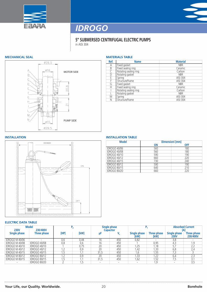
MECHANICAL SEAL
MOTOR SIDE
PUMP SIDE
MATERIALS TABLERef. Name MaterialA Fixed gasket NBRB Fixed sealing ring CeramicC Rotating sealing ring CarbonD Rotating gasket NBRE Spring AISI 304F Structure/frame AISI 304G Fixed gasket NBRH Fixed sealing ring CeramicI Rotating sealing ring CarbonL Rotating gasket NBRM Spring AISI 304N Structure/frame AISI 304
ELECTRIC DATA TABLEModel P2 Single phase P1 Absorbed Current
230V 230/400V Capacitor [A]Single phase Three phase [HP] [kW] µF Vc Single phase Three phase Single phase Three phase
[kW] [kW] 230V 230/400VIDROGO M 40/06 - 0,6 0,44 16 450 0,82 - 3,8 -IDROGO M 40/08 IDROGO 40/08 0,8 0,6 16 450 1 0,95 4,3 1,9IDROGO M 40/10 IDROGO 40/10 1 0,75 20 450 1,25 1,18 5,7 2,2IDROGO M 40/12 IDROGO 40/12 1,2 0,9 20 450 1,42 1,33 6,8 2,4IDROGO M 40/15 IDROGO 40/15 1,5 1,1 31,5 450 1,6 1,55 7,3 3IDROGO M 80/12 IDROGO 80/12 1,2 0,9 20 450 1,33 1,22 6,4 2,3IDROGO M 80/15 IDROGO 80/15 1,5 1,1 31,5 450 1,62 1,52 7,5 3,1
- IDROGO 80/20 2 1,5 - - - 1,9 - 3,5
INSTALLATION TABLEINSTALLATIONModel Dimensioni [mm]
ON OFFIDROGO 40/06 560 180IDROGO 40/08 560 180IDROGO 40/10 590 190IDROGO 40/12 660 220IDROGO 40/15 730 240IDROGO 80/12 590 190IDROGO 80/15 640 210IDROGO 80/20 660 220
Your Life, our Quality. Worldwide. 21 Borehole
SF66” SUBMERSED CENTRIFUGAL ELECTRIC PUMPS
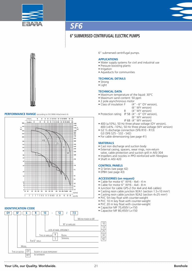
6” submersed centrifugal pumps.
APPLICATIONS• Water supply systems for civil and industrial use• Pressure boosting plants• Irrigation• Aqueducts for communities
TECHNICAL DETAILS• Strong• Light
TECHNICAL DATA• Maximum temperature of the liquid: 30°C• Maximum sand content: 50 ppm• 2 pole asynchronous motor• Class of insulation F (4” - 6” OY version),
(6” WY version)B (4” WY version)
• Protection rating IP 58 (4” - 6” OY version),(6” WY version)
IP 68 (4” WY version)• 400 (±10%), 50 Hz three phase voltage (OY version),
400 (+6% -10%), 50 Hz three phase voltage (WY version)• G2 ½ discharge connection (SF6 R10 - R13)
G3 (SF6 S25 - S32 - S42)• For cable dimensioning (see page 41)
MATERIALS• Cast iron discharge and suction body• External casing, spacers, wear rings, non-return
valve, cable protection and suction grill in AISI 304• Impellers and nozzles in PPO reinforced with fibreglass• Shaft in AISI 420
CONTROL PANELS• Q Series (see page 42)• EPBH (see page 43)
ACCESSORIES (on request)• Cable for motor 6” WY6 - 4x4 - 4 m• Cable for motor 6” WY6 - 4x4 - 8 m• Junction for cable GPS-2 (for 4x4 and 4x6 cables)• Casting resin cable junction 92A1 (section 1.5÷10 mm2)• Casting resin cable junction 92A2 (section 4÷25 mm2)• PVC 5m key float with counter-weight• PVC 10 m key float with counter-weight• PVC 20 m key float with counter-weight• Capacitor MF 70,450V L=150• Capacitor MF 80,450V L=150
PERFORMANCE RANGE (according to ISO 9906 Attachment A)
IDENTIFICATION CODE
6 R 13
MOTOR POWER IN KW
- /12 7,5
N° OF IMPELLERS
m3/h AT MAX. EFFICIENCY
TYPE OF IMPELLER
FOR 6” WELLS
MODEL
OY SF
TYPE OF MOTOR OYWY
IN BATH OF LIQUID REFRIGERANT
IN WATERBATH
1013253242
RS
RADIAL
SEMIAXIAL
Your Life, our Quality. Worldwide. 22 Borehole
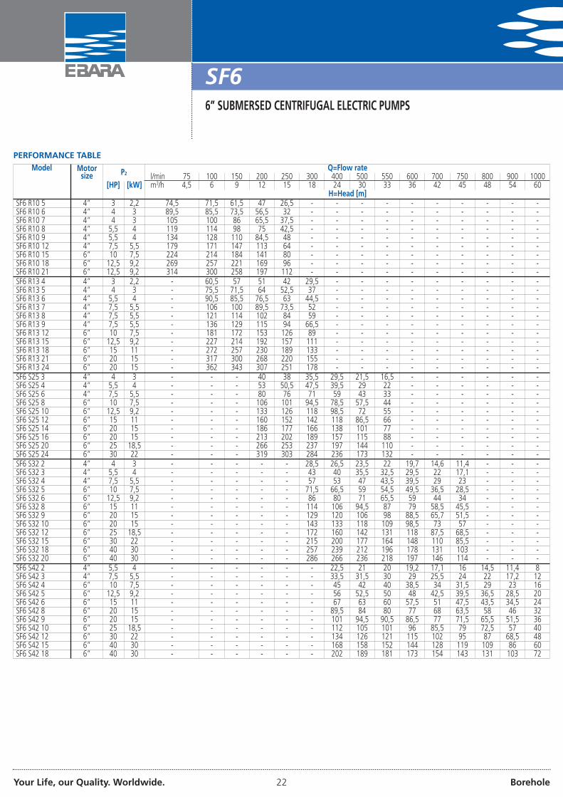
SF66” SUBMERSED CENTRIFUGAL ELECTRIC PUMPS
PERFORMANCE TABLEModel Motor
size P2 Q=Flow ratel/min 75 100 150 200 250 300 400 500 550 600 700 750 800 900 1000
[HP] [kW] m3/h 4,5 6 9 12 15 18 24 30 33 36 42 45 48 54 60H=Head [m]
SF6 R10 5 4” 3 2,2 74,5 71,5 61,5 47 26,5 - - - - - - - - - -SF6 R10 6 4” 4 3 89,5 85,5 73,5 56,5 32 - - - - - - - - - -SF6 R10 7 4” 4 3 105 100 86 65,5 37,5 - - - - - - - - - -SF6 R10 8 4” 5,5 4 119 114 98 75 42,5 - - - - - - - - - -SF6 R10 9 4” 5,5 4 134 128 110 84,5 48 - - - - - - - - - -SF6 R10 12 4” 7,5 5,5 179 171 147 113 64 - - - - - - - - - -SF6 R10 15 6” 10 7,5 224 214 184 141 80 - - - - - - - - - -SF6 R10 18 6” 12,5 9,2 269 257 221 169 96 - - - - - - - - - -SF6 R10 21 6” 12,5 9,2 314 300 258 197 112 - - - - - - - - - -SF6 R13 4 4” 3 2,2 - 60,5 57 51 42 29,5 - - - - - - - - -SF6 R13 5 4” 4 3 - 75,5 71,5 64 52,5 37 - - - - - - - - -SF6 R13 6 4” 5,5 4 - 90,5 85,5 76,5 63 44,5 - - - - - - - - -SF6 R13 7 4” 7,5 5,5 - 106 100 89,5 73,5 52 - - - - - - - - -SF6 R13 8 4” 7,5 5,5 - 121 114 102 84 59 - - - - - - - - -SF6 R13 9 4” 7,5 5,5 - 136 129 115 94 66,5 - - - - - - - - -SF6 R13 12 6” 10 7,5 - 181 172 153 126 89 - - - - - - - - -SF6 R13 15 6” 12,5 9,2 - 227 214 192 157 111 - - - - - - - - -SF6 R13 18 6” 15 11 - 272 257 230 189 133 - - - - - - - - -SF6 R13 21 6” 20 15 - 317 300 268 220 155 - - - - - - - - -SF6 R13 24 6” 20 15 - 362 343 307 251 178 - - - - - - - - -SF6 S25 3 4” 4 3 - - - 40 38 35,5 29,5 21,5 16,5 - - - - - -SF6 S25 4 4” 5,5 4 - - - 53 50,5 47,5 39,5 29 22 - - - - - -SF6 S25 6 4” 7,5 5,5 - - - 80 76 71 59 43 33 - - - - - -SF6 S25 8 6” 10 7,5 - - - 106 101 94,5 78,5 57,5 44 - - - - - -SF6 S25 10 6” 12,5 9,2 - - - 133 126 118 98,5 72 55 - - - - - -SF6 S25 12 6” 15 11 - - - 160 152 142 118 86,5 66 - - - - - -SF6 S25 14 6” 20 15 - - - 186 177 166 138 101 77 - - - - - -SF6 S25 16 6” 20 15 - - - 213 202 189 157 115 88 - - - - - -SF6 S25 20 6” 25 18,5 - - - 266 253 237 197 144 110 - - - - - -SF6 S25 24 6” 30 22 - - - 319 303 284 236 173 132 - - - - - -SF6 S32 2 4” 4 3 - - - - - 28,5 26,5 23,5 22 19,7 14,6 11,4 - - -SF6 S32 3 4” 5,5 4 - - - - - 43 40 35,5 32,5 29,5 22 17,1 - - -SF6 S32 4 4” 7,5 5,5 - - - - - 57 53 47 43,5 39,5 29 23 - - -SF6 S32 5 6” 10 7,5 - - - - - 71,5 66,5 59 54,5 49,5 36,5 28,5 - - -SF6 S32 6 6” 12,5 9,2 - - - - - 86 80 71 65,5 59 44 34 - - -SF6 S32 8 6” 15 11 - - - - - 114 106 94,5 87 79 58,5 45,5 - - -SF6 S32 9 6” 20 15 - - - - - 129 120 106 98 88,5 65,7 51,5 - - -SF6 S32 10 6” 20 15 - - - - - 143 133 118 109 98,5 73 57 - - -SF6 S32 12 6” 25 18,5 - - - - - 172 160 142 131 118 87,5 68,5 - - -SF6 S32 15 6” 30 22 - - - - - 215 200 177 164 148 110 85,5 - - -SF6 S32 18 6” 40 30 - - - - - 257 239 212 196 178 131 103 - - -SF6 S32 20 6” 40 30 - - - - - 286 266 236 218 197 146 114 - - -SF6 S42 2 4” 5,5 4 - - - - - - 22,5 21 20 19,2 17,1 16 14,5 11,4 8SF6 S42 3 4” 7,5 5,5 - - - - - - 33,5 31,5 30 29 25,5 24 22 17,2 12SF6 S42 4 6” 10 7,5 - - - - - - 45 42 40 38,5 34 31,5 29 23 16SF6 S42 5 6” 12,5 9,2 - - - - - - 56 52,5 50 48 42,5 39,5 36,5 28,5 20SF6 S42 6 6” 15 11 - - - - - - 67 63 60 57,5 51 47,5 43,5 34,5 24SF6 S42 8 6” 20 15 - - - - - - 89,5 84 80 77 68 63,5 58 46 32SF6 S42 9 6” 20 15 - - - - - - 101 94,5 90,5 86,5 77 71,5 65,5 51,5 36SF6 S42 10 6” 25 18,5 - - - - - - 112 105 101 96 85,5 79 72,5 57 40SF6 S42 12 6” 30 22 - - - - - - 134 126 121 115 102 95 87 68,5 48SF6 S42 15 6” 40 30 - - - - - - 168 158 152 144 128 119 109 86 60SF6 S42 18 6” 40 30 - - - - - - 202 189 181 173 154 143 131 103 72

Your Life, our Quality. Worldwide. 23 Borehole
SF6 R10 range PERFORMANCE CURVES(according to ISO 9906 Attachment A) IMPELLER DIAMETER: 118 mm
SF6 R13 range PERFORMANCE CURVES(according to ISO 9906 Attachment A) IMPELLER DIAMETER: 117 mm
SF6 S25 range PERFORMANCE CURVES(according to ISO 9906 Attachment A) IMPELLER DIAMETER: 111,5 mm
SF6 S32 range PERFORMANCE CURVES(according to ISO 9906 Attachment A) IMPELLER DIAMETER: 113,7 mm
SF66” SUBMERSED CENTRIFUGAL ELECTRIC PUMPS
Your Life, our Quality. Worldwide. 24 Borehole
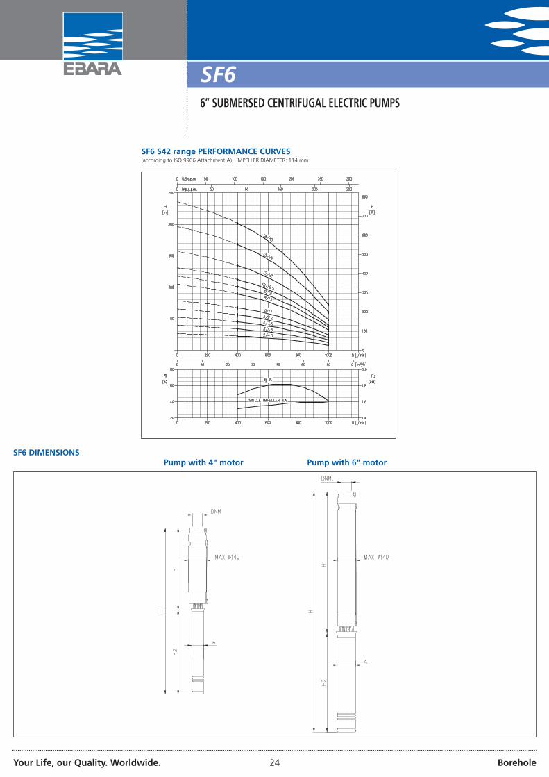
SF6 S42 range PERFORMANCE CURVES(according to ISO 9906 Attachment A) IMPELLER DIAMETER: 114 mm
SF66” SUBMERSED CENTRIFUGAL ELECTRIC PUMPS
SF6 DIMENSIONSPump with 4" motor Pump with 6" motor

Your Life, our Quality. Worldwide. 25 Borehole
SF66” SUBMERSED CENTRIFUGAL ELECTRIC PUMPS
DIMENSIONS TABLEModel Motor
size P2 Pump without motor Pump with motor in bath of liquid refrigerant Pump with motor in water bath
[HP] [kW] H1 DNM A H2 H A H2 H[mm] [mm] [mm] [mm] [mm] [mm] [mm]
SF6 R10 5 4” 3 2,2 478 G2½ 93 417,5 895,5 95,3 353,5 831,5SF6 R10 6 4” 4 3 516 G2½ 93 577,5 1093,5 95,3 420,5 936,5SF6 R10 7 4” 4 3 554 G2½ 93 577,5 1131,5 95,3 420,5 974,5SF6 R10 8 4” 5,5 4 592 G2½ 93 577,5 1169,5 95,3 580,5 1172,5SF6 R10 9 4” 5,5 4 630 G2½ 93 577,5 1207,5 95,3 580,5 1210,5SF6 R10 12 4” 7,5 5,5 744 G2½ 93 647,5 1391,5 95,3 695,5 1439,5SF6 R10 15 6” 10 7,5 858 G2½ 140 600 1458 136,7 647 1505SF6 R10 18 6” 12,5 9,2 972 G2½ 140 600 1572 136,7 679 1651SF6 R10 21 6” 12,5 9,2 1086 G2½ 140 600 1686 136,7 679 1765SF6 R13 4 4” 3 2,2 440 G2½ 93 417,5 857,5 95,3 353,5 793,5SF6 R13 5 4” 4 3 478 G2½ 93 577,5 1055,5 95,3 420,5 898,5SF6 R13 6 4” 5,5 4 516 G2½ 93 577,5 1093,5 95,3 580,5 1096,5SF6 R13 7 4” 7,5 5,5 554 G2½ 93 647,5 1201,5 95,3 695,5 1249,5SF6 R13 8 4” 7,5 5,5 592 G2½ 93 647,5 1239,5 95,3 695,5 1287,5SF6 R13 9 4” 7,5 5,5 630 G2½ 93 647,5 1277,5 95,3 695,5 1325,5SF6 R13 12 6” 10 7,5 744 G2½ 140 600 1344 136,7 647 1391SF6 R13 15 6” 12,5 9,2 858 G2½ 140 600 1458 136,7 679 1537SF6 R13 18 6” 15 11 972 G2½ 140 700 1672 136,7 712 1684SF6 R13 21 6” 20 15 1086 G2½ 140 760 1846 136,7 777 1863SF6 R13 24 6” 20 15 1200 G2½ 140 760 1960 136,7 777 1977SF6 S25 3 4” 4 3 459 G3 93 577,5 1036,5 95,3 420,5 879,5SF6 S25 4 4” 5,5 4 516 G3 93 577,5 1093,5 95,3 580,5 1096,5SF6 S25 6 4” 7,5 5,5 630 G3 93 647,5 1277,5 95,3 695,5 1325,5SF6 S25 8 6” 10 7,5 744 G3 140 600 1344 136,7 647 1391SF6 S25 10 6” 12,5 9,2 858 G3 140 600 1458 136,7 679 1537SF6 S25 12 6” 15 11 972 G3 140 700 1672 136,7 712 1684SF6 S25 14 6” 20 15 1086 G3 140 760 1846 136,7 777 1863SF6 S25 16 6” 20 15 1200 G3 140 760 1960 136,7 777 1977SF6 S25 20 6” 25 18,5 1480 G3 140 830 2310 136,7 842 2322SF6 S25 24 6” 30 22 1708 G3 140 890 2598 136,7 907 2615SF6 S32 2 4” 4 3 408 G3 93 577,5 985,5 95,3 420,5 828,5SF6 S32 3 4” 5,5 4 468 G3 93 577,5 1045,5 95,3 580,5 1048,5SF6 S32 4 4” 7,5 5,5 528 G3 93 647,5 1175,5 95,3 695,5 1223,5SF6 S32 5 6” 10 7,5 588 G3 140 600 1188 136,7 647 1235SF6 S32 6 6” 12,5 9,2 648 G3 140 600 1248 136,7 679 1327SF6 S32 8 6” 15 11 768 G3 140 700 1468 136,7 712 1480SF6 S32 9 6” 20 15 828 G3 140 760 1588 136,7 777 1605SF6 S32 10 6” 20 15 888 G3 140 760 1648 136,7 777 1665SF6 S32 12 6” 25 18,5 1008 G3 140 830 1838 136,7 842 1850SF6 S32 15 6” 30 22 1188 G3 140 890 2078 136,7 907 2095SF6 S32 18 6” 40 30 1420 G3 140 1037 2457 136,7 1037 2457SF6 S32 20 6” 40 30 1540 G3 140 1037 2577 136,7 1037 2577SF6 S42 2 4” 5,5 4 408 G3 93 577,5 985,5 95,3 580,5 988,5SF6 S42 3 4” 7,5 5,5 468 G3 93 647,5 1115,5 95,3 695,5 1163,5SF6 S42 4 6” 10 7,5 528 G3 140 600 1128 136,7 647 1175SF6 S42 5 6” 12,5 9,2 588 G3 140 600 1188 136,7 679 1267SF6 S42 6 6” 15 11 648 G3 140 700 1348 136,7 712 1360SF6 S42 8 6” 20 15 768 G3 140 760 1528 136,7 777 1545SF6 S42 9 6” 20 15 828 G3 140 760 1588 136,7 777 1605SF6 S42 10 6” 25 18,5 888 G3 140 830 1718 136,7 842 1730SF6 S42 12 6” 30 22 1008 G3 140 890 1898 136,7 907 1915SF6 S42 15 6” 40 30 1188 G3 140 1030 2218 136,7 1037 2225SF6 S42 18 6” 40 30 1420 G3 140 1030 2450 136,7 1037 2457

Your Life, our Quality. Worldwide. 26 Borehole
SECTIONAL VIEW
MATERIALS TABLERef. Name Material Ref. Name Material
1130.1 6” suction inlet EN 1.4301 (AISI 304) 3412 Upper casing EN 1.4401 (AISI 316L) + ceramic1130.2 4” suction inlet EN 1.4301 (AISI 304) 3420 Intermediate casing EN 1.4401 (AISI 316L) + ceramic1140 Upper support (PPO mod.+ G.F.) and NBR 3650.1 Thrust block bearing - washer Anti-friction material1410 Nozzle (PPO mod.+ G.F.) + EN 1.4301 (AISI 304) 3650.2 Thrust block bearing - washer EN 1.4301 (AISI 304)1414 Spacer EN 1.4301 (AISI 304) 4511 O-Ring NBR1471 Nozzle disc (PPO mod.+ G.F.) + EN 1.4301 (AISI 304) 6310.1 G 2½ discharge EN 1.4301 (AISI 304)
1471.1 Nozzle disc (PPO mod.+ G.F.) + EN 1.4301 (AISI 304) 6310.2 G 3 discharge EN 1.4301 (AISI 304)1910 Lower support (PPO mod.+ G.F.) + Polyamide 6320 O-Ring NBR
2110.1 Shaft 4” EN 1.4021 (AISI 420) 6330 Valve EN 1.4301 (AISI 304)2110.2 Shaft 6” EN 1.4021 (AISI 420) 6340 Valve seat EN 1.4301 (AISI 304)2250 Impeller PPO mod.+ G.F. 6531 Suction filter EN 1.4301 (AISI 304)
2420.1 Shaft casing PPO mod.+ G.F. 6544 Circlip EN 1.4301 (AISI 304)2420.2 Shaft casing PPO mod.+ G.F. 6577.1 Set of screws EN 1.4301 (AISI 304)2420.3 Shaft casing PPO mod.+ G.F. 6577.3 Screw EN 1.4301 (AISI 304)2460 Shaft casing PPO mod.+ G.F. 7000.1 Joint (with screw) EN 1.4105 (AISI 430F)
2460.1 Bush PPO mod.+ G.F. 7000.2 Joint (with screw) EN 1.4105 (AISI 430F)2910 Screw EN 1.4301 (AISI 304) 7416 Screw EN 1.4301 (AISI 304)2911 Washer EN 1.4301 (AISI 304) 8210 Pump body EN 1.4301 (AISI 304)3044 Intermediate support + rubber bearing (PPO mod.+ G.F.) and NBR 8361 Isolating cover EN 1.4301 (AISI 304)3411 Lower case EN 1.4401 (AISI 316L) + ceramic covering 8363 Cable stay EN 1.4301 (AISI 304)
SF66” SUBMERSED CENTRIFUGAL ELECTRIC PUMPS

Your Life, our Quality. Worldwide. 27 Borehole
ELECTRIC DATA TABLE SF6 WITH MOTOR IN BATH OF LIQUID REFRIGERANT
ELECTRIC DATA TABLE SF6 WITH MOTOR IN WATERBATH
Motor P2 P1 Voltage IN IA Efficiency Powerfactor
[HP] [kW] [kW] [V] [A] [A] [%]
4”
3 2,2 2,82 400V 6 24 78 0,704 3 3,89 400V 7,9 34 77 0,75
5,5 4 5,06 400V 10 47 79 0,777,5 5,5 7,24 400V 14,4 58 76 0,79
6”
10 7,5 9,62 400V 17,5 96,3 78 0,8512,5 9,2 11,50 400V 21 105 80 0,8215 11 13,25 400V 24,1 123 83 0,8320 15 18,29 400V 31,5 164 82 0,8825 18,5 22,56 400V 41,5 208 82 0,8530 22 26,51 400V 48 216 83 0,8640 30 34,88 400V 62 310 86 0,86
Motor P2 P1 Voltage IN IA Efficiency Powerfactor
[HP] [kW] [kW] [V] [A] [A] [%]
4”
3 2,2 2,93 400V 5,9 28,9 75 0,754 3 3,95 400V 7,8 41,6 76 0,75
5,5 4 5,1 400V 10 58 78 0,787,5 5,5 7,23 400V 13,7 76 76 0,79
6”
10 7,5 9,49 400V 16 83 79 0,8612,5 9,2 11,35 400V 20,7 112 81 0,8015 11 13,58 400V 23,3 129 81 0,8520 15 18,52 400V 31,3 169 81 0,8525 18,5 22,56 400V 38,5 231 82 0,8530 22 26,51 400V 45,3 268 83 0,8640 30 36,14 400V 63,5 393 83 0,84
SF66” SUBMERSED CENTRIFUGAL ELECTRIC PUMPS

Your Life, our Quality. Worldwide. 28 Borehole
6BHE6” SUBMERSED CENTRIFUGAL PUMPSin AISI 304
Pumps submersed in stainless steel for 6" deep wells in AISI 304.
APPLICATIONS• Water provisioning from deep wells• Water supply and pressure boosting• Irrigation systems• Treating waters, filtering and reverse osmosis• Industrial cooling systems• Fountains and fire-fighting plants
TECHNICAL DETAILS• The range includes: three models with radial discharge for high heads
and medium flow rates and two models with semi-axial discharge formedium heads and high flow rates
• High resistance to corrosion• Reliable• Compact• Also suitable for horizontal functioning
TECHNICAL DATA• Maximum sand content: 50 ppm• Maximum temperature of the liquid: 50°CThe pump and the motor are supplied separately.
• 2 pole motor in bath of liquid refrigerant (OY) or in water bath (WY),• Protection rating IP58 (OY), IP68 (WY)• 380V -10% 50 Hz three phase voltage (OY)
400V +6% 50 Hz three phase voltage (OY)380V -10% 50 Hz three phase voltage (WY)415V +6% 50 Hz three phase voltage (WY)
• Class of insulation F (4” - -6” OY version)(6” WY version)
B (4” WY version)• L version in AISI 316 stainless steel available on request• Motor support for coupling to 4" motors• For cable dimensioning (see page 41)
MATERIALS• Entirely in stainless steel• Wear ring in PTFE• Shaft guide support in ceramic
CONTROL PANELS• Q Series (see page 42)• 1EPBH (see page 43)
ACCESSORIES (on request)• Cable for motor 6” WY6 - 4x4 - 4 m• Cable for motor 6” WY6 - 4x4 - 8 m• Junction for cable GPS-2 (for 4x1.5 and 4x2.5 cables)• Casting resin cable junction 92A1 (section 1.5÷10 mm2)• Casting resin cable junction 92A2 (section 4÷25 mm2)• PVC 5m key float with counter-weight• PVC 10 m key float with counter-weight• PVC 20 m key float with counter-weight• Capacitor MF 70,450V L=150• Capacitor MF 80,450V L=150
PERFORMANCE RANGE (according to ISO 9906 Attachment A)
IDENTIFICATION CODE
4 BHE 30 - /5 55
N° OF IMPELLERS
m3/h AT MAX. EFFICIENCY
MODEL
4” MOTOR
FOR 6” WELLS
OY 6
TYPE OF MOTOR OYWY
IN BATH OF LIQUID REFRIGERANT
IN WATERBATH
MOTOR POWER IN KW X10
- /
VERSION IN AISI 316
L

Your Life, our Quality. Worldwide. 29 Borehole
6BHE6” SUBMERSED CENTRIFUGAL PUMPSin AISI 304
PERFORMANCE TABLEModel Motor
sizeP2 Q=Flow rate
l/min 100 150 200 250 300 400 450 525 600 700 825 950 1050 1167[HP] [kW] m3/h 6 9 12 15 18 24 27 31,5 36 42 49,5 57 63 70
H=Head [m]64 BHE 14 - 5 4” 3 2,2 50,5 46,5 40,5 31 18 - - - - - - - - -64 BHE 14 - 8 4” 5,5 4 81 74,5 64,5 49,5 28,8 - - - - - - - - -6 BHE 14 - 8 6” 5,5 4 81 74,5 64,5 49,5 28,8 - - - - - - - - -64 BHE 14 - 13 4” 7,5 5,5 131 121 105 80,5 47 - - - - - - - - -6 BHE 14 - 13 6” 7,5 5,5 131 121 105 80,5 47 - - - - - - - - -6 BHE 14 - 17 6” 10 7,5 172 158 137 105 61 - - - - - - - - -6 BHE 14 - 22 6” 12,5 9,2 222 205 178 136 79 - - - - - - - - -6 BHE 14 - 26 6” 15 11 263 242 210 161 93,5 - - - - - - - - -6 BHE 14 - 32 6” 20 15 323 298 258 198 115 - - - - - - - - -6 BHE 14 - 36 6” 20 15 364 335 291 223 130 - - - - - - - - -6 BHE 14 - 42 6” 25 18,5 424 391 339 260 151 - - - - - - - - -64 BHE 19 - 6 4” 5,5 4 - 65 62 57,5 51,5 33,9 22,8 - - - - - - -6 BHE 19 - 6 6” 5,5 4 - 65 62 57,5 51,5 33,9 22,8 - - - - - - -64 BHE 19 - 9 4” 7,5 5,5 - 97 92,5 86,5 77,5 51 34,2 - - - - - - -6 BHE 19 - 9 6” 7,5 5,5 - 97 92,5 86,5 77,5 51 34,2 - - - - - - -6 BHE 19 - 12 6” 10 7,5 - 130 124 115 103 68 45,5 - - - - - - -6 BHE 19 - 15 6” 12,5 9,2 - 162 155 144 129 85 57 - - - - - - -6 BHE 19 - 18 6” 15 11 - 194 185 173 155 102 68,5 - - - - - - -6 BHE 19 - 21 6” 20 15 - 227 216 202 181 119 80 - - - - - - -6 BHE 19 - 24 6” 20 15 - 259 247 230 206 136 91 - - - - - - -6 BHE 19 - 28 6” 25 18,5 - 302 288 269 241 158 106 - - - - - - -6 BHE 19 - 30 6” 25 18,5 - 324 309 288 258 170 114 - - - - - - -6 BHE 19 - 33 6” 30 22 - 356 340 317 284 186 125 - - - - - - -6 BHE 19 - 36 6” 30 22 - 389 371 346 310 203 137 - - - - - - -6 BHE 19 - 39 6” 40 30 - 421 402 374 335 220 148 - - - - - - -6 BHE 19 - 42 6” 40 30 - 454 433 403 361 237 160 - - - - - - -64 BHE 30 - 3 4” 4 3 - - 34,2 33,2 31,8 28,6 26,4 22,1 17,3 10,5 - - - -64 BHE 30 - 4 4” 5,5 4 - - 45,5 44 42,5 38,2 35,2 29,5 23 14 - - - -6 BHE 30 - 4 6” 5,5 4 - - 45,5 44 42,5 38,2 35,2 29,5 23 14 - - - -64 BHE 30 - 5 4” 7,5 5,5 - - 57 55,5 53 47,5 44 36,9 28,8 17,5 - - - -6 BHE 30 - 5 6” 7,5 5,5 - - 57 55,5 53 47,5 44 36,9 28,8 17,5 - - - -6 BHE 30 - 7 6” 10 7,5 - - 80 77,5 74 67 61,5 51,5 40,5 24,5 - - - -6 BHE 30 - 11 6” 15 11 - - 125 122 117 105 97 81 63,5 38,5 - - - -6 BHE 30 - 15 6” 20 15 - - 171 166 159 143 132 111 86,5 52,5 - - - -6 BHE 30 - 19 6” 25 18,5 - - 217 210 201 181 167 140 109 66,5 - - - -6 BHE 30 - 23 6” 30 22 - - 262 254 244 219 202 170 132 80,5 - - - -6 BHE 30 - 27 6” 40 30 - - 308 299 286 258 238 199 155 94,5 - - - -6 BHE 30 - 31 6” 40 30 - - 353 343 329 296 273 229 178 109 - - - -6 BHE 30 - 33 6” 50 37 - - 376 365 350 315 290 244 190 116 - - - -6 BHE 30 - 36 6” 50 37 - - 410 398 382 343 317 266 207 126 - - - -64 BHE 44 - 2 4” 4 3 - - - - 25,2 23,5 22,6 21,2 19,6 17,4 14,2 10,6 - -64 BHE 44 - 3 4” 7,5 5,5 - - - - 37,8 35,3 33,9 31,7 29,4 26 21,3 15,9 - -6 BHE 44 - 3 6” 7,5 5,5 - - - - 37,8 35,3 33,9 31,7 29,4 26 21,3 15,9 - -6 BHE 44 - 5 6” 10 7,5 - - - - 63 59 56,5 53 49 43,5 35,5 26,5 - -6 BHE 44 - 7 6” 15 11 - - - - 88 82,5 79 74 68,5 61 49,5 37,1 - -6 BHE 44 - 9 6” 20 15 - - - - 113 106 102 95 88 78 64 47,5 - -6 BHE 44 - 10 6” 20 15 - - - - 126 118 113 106 98 87 71 53 - -6 BHE 44 - 12 6” 25 18,5 - - - - 151 141 136 127 118 104 85 63,5 - -6 BHE 44 - 15 6” 30 22 - - - - 189 176 170 159 147 130 107 79,5 - -6 BHE 44 - 18 6” 40 30 - - - - 227 212 203 190 176 156 128 95,5 - -6 BHE 44 - 20 6” 40 30 - - - - 252 235 226 212 196 174 142 106 - -6 BHE 44 - 22 6” 50 37 - - - - 277 259 249 233 216 191 156 117 - -6 BHE 44 - 24 6” 50 37 - - - - 302 282 271 254 235 208 170 127 - -64 BHE 58 - 2 4” 4 3 - - - - - 23,2 22,5 21,2 19,7 17,7 15 12 9,3 664 BHE 58 - 3 4” 7,5 5,5 - - - - - 34,8 33,7 31,9 29,6 26,6 22,5 18 14 96 BHE 58 - 3 6” 7,5 5,5 - - - - - 34,8 33,7 31,9 29,6 26,6 22,5 18 14 96 BHE 58 - 5 6” 10 7,5 - - - - - 58 56 53 49,5 44,5 37,5 30 23,3 156 BHE 58 - 7 6” 15 11 - - - - - 81 78,5 74,5 69 62 52,5 42 32,6 216 BHE 58 - 9 6” 20 15 - - - - - 104 101 95,5 89 79,5 67,5 54 42 276 BHE 58 - 10 6” 20 15 - - - - - 116 112 106 98,5 88,5 75 60 46,5 306 BHE 58 - 12 6” 25 18,5 - - - - - 139 135 127 118 106 90 72 56 366 BHE 58 - 14 6” 30 22 - - - - - 162 157 149 138 124 105 84 65 426 BHE 58 - 16 6” 40 30 - - - - - 186 180 170 158 142 120 96 74,5 486 BHE 58 - 18 6” 40 30 - - - - - 209 202 191 178 159 135 108 83,5 546 BHE 58 - 20 6” 50 37 - - - - - 232 225 212 197 177 150 120 93 606 BHE 58 - 23 6” 50 37 - - - - - 267 259 244 227 204 173 138 107 69

Your Life, our Quality. Worldwide. 30 Borehole
6(4) BHE 14 range PERFORMANCE CURVES(according to ISO 9906 Attachment A)
6(4)BHE 19 range PERFORMANCE CURVES(according to ISO 9906 Attachment A)
6(4)BHE 30 range PERFORMANCE CURVES(according to ISO 9906 Attachment A)
6(4)BHE 44 range PERFORMANCE CURVES(according to ISO 9906 Attachment A)
6BHE6” SUBMERSED CENTRIFUGAL PUMPSin AISI 304

Your Life, our Quality. Worldwide. 31 Borehole
6(4)BHE 58 range PERFORMANCE CURVES(according to ISO 9906 Attachment A)
DIMENSIONSPump with 4” motor connection (64BHE) Pump with 6” motor connection (6BHE)
6BHE6” SUBMERSED CENTRIFUGAL PUMPSin AISI 304
DIMENSIONS TABLE
6BHEwithout motor
64BHEwith 4" motor
6BHEwith 6" motor
Version withsingle cable
Version withdouble cable
145
-
146,5
141
141
144

Your Life, our Quality. Worldwide. 32 Borehole
DIMENSIONS TABLEModel Motor
sizeP2 Pump without motor Pump with motor in bath of liquid refrigerant Pump with motor in water bath
[HP] [kW] H1 DNM Weight A H2 H Weight A H2 H Weight[mm] [kg] [mm] [mm] [mm] [kg] [mm] [mm] [mm] [kg]
64 BHE 14 - 5 4” 3 2,2 356 G2 ½ 10,5 97 466 820 25 95 440 794 2764 BHE 14 - 8 4” 5,5 4 446 G2 ½ 13 97 574 1018 33 95 583 1027 376 BHE 14 - 8 6” 5,5 4 446 G2 ½ 13 139 540 986 51 137 581 1027 5164 BHE 14 - 13 4” 7,5 5,5 596 G2 ½ 16,5 97 644 1238 39 95 698 1291 466 BHE 14 - 13 6” 7,5 5,5 596 G2 ½ 16,5 139 570 1166 57 137 614 1210 586 BHE 14 - 17 6” 10 7,5 716 G2 ½ 19,5 139 600 1316 62 137 646 1362 656 BHE 14 - 22 6” 12,5 9,2 866 G2 ½ 23 139 600 1466 68 137 679 1545 716 BHE 14 - 26 6” 15 11 986 G2 ½ 26 139 700 1686 74 137 711 1697 776 BHE 14 - 32 6” 20 15 1166 G2 ½ 30,5 139 760 1926 85 137 776 1942 876 BHE 14 - 36 6” 20 15 1286 G2 ½ 33,5 139 760 2046 88 137 776 2062 906 BHE 14 - 42 6” 25 18,5 1466 G2 ½ 38 139 830 2296 103 137 842 2308 10164 BHE 19 - 6 4” 5,5 4 431 G2 ½ 12,0 97 574 1003 32 95 583 1012 366 BHE 19 - 6 6” 5,5 4 431 G2 ½ 12,0 139 540 971 50 137 581 1012 5064 BHE 19 - 9 4” 7,5 5,5 543,5 G2 ½ 14,5 97 644 1185 37 95 698 1239 446 BHE 19 - 9 6” 7,5 5,5 543,5 G2 ½ 14,5 139 570 1114 55 137 614 1158 566 BHE 19 - 12 6” 10 7,5 656 G2 ½ 16,5 139 600 1256 59 137 646 1302 626 BHE 19 - 15 6” 12,5 9,2 768,5 G2 ½ 19,0 139 600 1369 64 137 679 1447 676 BHE 19 - 18 6” 15 11 881 G2 ½ 21,5 139 700 1581 70 137 711 1592 726 BHE 19 - 21 6” 20 15 993,5 G2 ½ 24,0 139 760 1754 78 137 776 1770 816 BHE 19 - 24 6” 20 15 1106 G2 ½ 26,5 139 760 1866 81 137 776 1882 836 BHE 19 - 28 6” 25 18,5 1256 G2 ½ 30,0 139 830 2086 95 137 842 2098 936 BHE 19 - 30 6” 25 18,5 1331 G2 ½ 31,5 139 830 2161 97 137 842 2173 956 BHE 19 - 33 6” 30 22 1443,5 G2 ½ 34,0 139 890 2334 104 137 907 2350 1036 BHE 19 - 36 6” 30 22 1556 G2 ½ 36,5 139 890 2446 107 137 907 2463 1066 BHE 19 - 39 6” 40 30 1668 G2 ½ 39,0 139 1030 2698 129 137 1037 2705 1236 BHE 19 - 42 6” 40 30 1853 G2 ½ 42,0 139 1030 2883 132 137 1037 2890 12664 BHE 30 - 3 4” 4 3 365,5 G3 10,5 97 544 907 30 95 507 870 3064 BHE 30 - 4 4” 5,5 4 412 G3 11,5 97 574 984 32 95 583 993 366 BHE 30 - 4 6” 5,5 4 412 G3 11,5 139 540 952 50 137 581 993 4964 BHE 30 - 5 4” 7,5 5,5 458,5 G3 12,5 97 644 1100 35 95 698 1154 426 BHE 30 - 5 6” 7,5 5,5 458,5 G3 12,5 139 570 1029 53 137 614 1073 546 BHE 30 - 7 6” 10 7,5 551,5 G3 14,5 139 600 1152 57 137 646 1198 606 BHE 30 - 11 6” 15 11 737,5 G3 18,5 139 700 1438 67 137 711 1449 696 BHE 30 - 15 6” 20 15 923,5 G3 22,5 139 700 1624 77 137 776 1700 796 BHE 30 - 19 6” 25 18,5 1109,5 G3 26,0 139 830 1940 91 137 842 1951 896 BHE 30 - 23 6” 30 22 1295,5 G3 30,0 139 890 2186 100 137 907 2202 996 BHE 30 - 27 6” 40 30 1481,5 G3 34,0 139 1030 2512 124 137 1037 2518 1186 BHE 30 - 31 6” 40 30 1667,5 G3 38,0 139 1030 2698 128 137 1037 2704 1226 BHE 30 - 33 6” 50 37 1760 G3 40,0 - - - - 137 1405 3165 1756 BHE 30 - 36 6” 50 37 1899,5 G3 43,0 - - - - 137 1405 3304 17864 BHE 44 - 2 4” 4 3 365,5 G3 11,0 97 544 907 30 95 507 870 3064 BHE 44 - 3 4” 7,5 5,5 458,5 G3 13,5 97 644 1100 36 95 698 1154 436 BHE 44 - 3 6” 7,5 5,5 458,5 G3 13,5 139 570 1029 54 137 614 1073 556 BHE 44 - 5 6” 10 7,5 644,5 G3 18,0 139 600 1245 60 137 646 1291 636 BHE 44 - 7 6” 15 11 830,5 G3 22,5 139 700 1531 71 137 711 1542 736 BHE 44 - 9 6” 20 15 1016,5 G3 27,0 139 760 1777 81 137 776 1793 846 BHE 44 - 10 6” 20 15 1109,5 G3 29,5 139 760 1870 84 137 776 1886 866 BHE 44 - 12 6” 25 18,5 1295,5 G3 34,0 139 830 2126 99 137 842 2137 976 BHE 44 - 15 6” 30 22 1574,5 G3 40,5 139 890 2465 111 137 907 2481 1106 BHE 44 - 18 6” 40 30 1853,5 G3 47,5 139 1030 2884 138 137 1037 2890 1316 BHE 44 - 20 6” 40 30 2039,5 G3 52,0 139 1030 3070 142 137 1037 3076 1366 BHE 44 - 22 6” 50 37 2225,5 G3 56,5 - - - - 137 1405 3630 1926 BHE 44 - 24 6” 50 37 2411 G3 61,0 - - - - 137 1405 3816 19664 BHE 58 - 2 4” 4 3 365,5 G3 11,5 97 544 907 31 95 507 870 3164 BHE 58 - 3 4” 7,5 5,5 458,5 G3 13,5 97 644 1100 36 95 698 1154 436 BHE 58 - 3 6” 7,5 5,5 458,5 G3 13,5 139 570 1029 54 137 614 1073 556 BHE 58 - 5 6” 10 7,5 644,5 G3 18,0 139 600 1245 60 137 646 1291 636 BHE 58 - 7 6” 15 11 830,5 G3 23,0 139 700 1531 71 137 711 1542 746 BHE 58 - 9 6” 20 15 1016,5 G3 27,5 139 760 1777 82 137 776 1793 846 BHE 58 - 10 6” 20 15 1109,5 G3 30,0 139 760 1870 84 137 776 1886 876 BHE 58 - 12 6” 25 18,5 1295,5 G3 34,5 139 830 2126 100 137 842 2137 986 BHE 58 - 14 6” 30 22 1481,5 G3 39,0 139 890 2372 109 137 907 2388 1086 BHE 58 - 16 6” 40 30 1667,5 G3 44,0 139 1030 2698 134 137 1037 2704 1286 BHE 58 - 18 6” 40 30 1853,5 G3 48,5 139 1030 2884 139 137 1037 2890 1326 BHE 58 - 20 6” 50 37 2040 G3 52,0 - - - - 137 1405 3445 1876 BHE 58 - 23 6” 50 37 2318 G3 60,0 - - - - 137 1405 3723 195
6BHE6” SUBMERSED CENTRIFUGAL PUMPSin AISI 304

Your Life, our Quality. Worldwide. 33 Borehole
6BHE6” SUBMERSED CENTRIFUGAL PUMPSin AISI 304
SECTIONAL VIEW6BHE 14-19-30 6BHE 44-58
MATERIALS TABLERef. Name Material Ref. Name Material10.00 External casing with discharge body EN 1.4401 (AISI 316) 30.03 Thrust block washer EN 1.4401 (AISI 316)10.01 Valve EN 1.4401 (AISI 316) 30.04 Upper bearing EN 1.4460 (AISI 329) + Ceramic covering10.02 O-Ring kit NBR 30.05 Screw and washer EN 1.4401 (AISI 316)10.03 Support screw and blocking EN 1.4401 (AISI 316) 30.06 Thrust block PTFE10.04 Discharge stage EN 1.4401 (AISI 316) 40.00 Intermediate stage EN 1.4301 (AISI 304) (standard version)10.05 Upper bush NBR EN 1.4401 (AISI 316) (L version)20.00 Motor support EN 1.4401 (AISI 316) 40.01 Intermediate bush NBR20.01 Strainer EN 1.4401 (AISI 316) 40.02 Intermediate stage + Wear ring EN 1.4401 (AISI 316) / PTFE20.02 Isolating cover EN 1.4401 (AISI 316) Wear ring PTFE20.03 Spacer EN 1.4401 (AISI 316) 40.03 Intermediate stage (suction) EN 1.4401 (AISI 316)20.04 Flange and bolt EN 1.4401 (AISI 316) 50.00 Impeller EN 1.4301 (AISI 304) ( standard version)30.00 Shaft with joint EN 1.4401 (AISI 316) EN 1.4401 (AISI 316) ( L version)30.01 Lower spacer EN 1.4401 (AISI 316) 50.01 Intermediate bearing EN 1.4301 (AISI 304) ( standard version)30.02 Upper spacer EN 1.4401 (AISI 316) EN 1.4401 (AISI 316) (L version)

Your Life, our Quality. Worldwide. 34 Borehole
ELECTRIC DATA TABLE 6(4)BHE WITH MOTOR IN BATH OF LIQUID REFRIGERANT
ELECTRIC DATA TABLE 6(4)BHE WITH MOTOR IN WATERBATH
6BHE6” SUBMERSED CENTRIFUGAL PUMPSin AISI 304
Motor P2 P1 Voltage IN IA Efficiency Powerfactor
[HP] [kW] [kW] [V] [A] [A] [%]
4”
3 2,2 2,97 380/400 6,0/6,2 24 74 0,764 3 4 380/400 7,9/8,0 34 75 0,78
5,5 4 5,13 380/400 10,0/10,2 47 75 0,787,5 5,5 7,24 380/400 14,0/14,4 58 76 0,79
6”
5,5 4 5,26 380/400 8,8 45 76 0,827,5 5,5 7,05 380/400 12,5 64 78 0,8210 7,5 9,74 380/400 16,9 78 77 0,82
12,5 9,2 11,50 380/400 21,5 95 80 0,8115 11 13,25 380/400 23,7 121 83 0,8320 15 18,29 380/400 30,4 160 82 0,8525 18,5 22,56 380/400 38,3 225 82 0,8530 22 26,51 380/400 44 250 83 0,8640 30 34,88 380/400 62 330 86 0,86
Motor P2 P1 Voltage IN IA Efficiency Powerfactor
[HP] [kW] [kW] [V] [A] [A] [%]
4”
3 2,2 2,93 400 5,9 28,9 75 0,754 3 3,95 400 7,8 41,6 76 0,75
5,5 4 5,13 400 10 58 78 0,787,5 5,5 7,24 400 13,7 76 76 0,79
6”
5,5 4 5,13 400 9,3 43 78 0,827,5 5,5 6,96 400 12,5 64 79 0,8210 7,5 9,49 400 16 83 79 0,86
12,5 9,2 11,36 400 20,7 112 81 0,8015 11 13,58 400 23,3 129 81 0,8520 15 18,52 400 31,3 169 81 0,8525 18,5 22,56 400 38,5 231 82 0,8530 22 26,51 400 45,3 268 83 0,8440 30 36,14 400 63,5 393 83 0,8450 37 43,79 400 73 410 84,5 0,87

Your Life, our Quality. Worldwide. 35 Borehole
8BHEL8” SUBMERSED CENTRIFUGAL PUMPSin AISI 316
Submersed electric pump with semi-axial discharge in AISI 316 stainlesssteel for wells with depth of 8” and over.This range of submersed pumps has been developed specifically for highflow rate pumping requirements.
APPLICATIONS• Water provisioning from deep wells• Water supply and pressure boosting• Irrigation systems• Treating waters, filtering and reverse osmosis• Industrial cooling systems• Fountains• Fire-fighting systems
TECHNICAL DETAILS• Corrosion-proof• Strong• Reliable• Compact• Also suitable for horizontal functioning
TECHNICAL DATA• Maximum sand content: 50 ppm• Maximum temperature of the liquid: 50°C• 2 pole motor in bath of liquid refrigerant (OY) or in water bath (WY),• Protection rating IP58 (OY), IP68 (WY)• 380V -10% 50 Hz three phase voltage (OY)
400V +6% 50 Hz three phase voltage (OY)380V -10% 50 Hz three phase voltage (WY)415V +6% 50 Hz three phase voltage (WY)
• Class of insulation F (6” OY version)(8” WY version)
B (6” WY version)• Motor support for coupling to 6" motors• Motor joint and coupling flange in compliance with NEMA Standards• For cables dimensioning (see page 41)
MATERIALS• Completely in AISI 316• Impellers and semi-axial discharge nozzles in stainless steel• Wear ring in Teflon, shaft guide support in ceramic
CONTROL PANELS• 1EPBH (see page 43)
ACCESSORIES (on request)• Junction for cable GPS-1 (for 4x1.5 and 4x2.5 cables)• Junction for cable GPS-2 (for 4x4 and 4x6 cables)• Casting resin cable junction 92A1 (section 1.5÷10 mm2)• Casting resin cable junction 92A2 (section 4÷25 mm2)• PVC 5m key float with counter-weight• PVC 10 m key float with counter-weight• PVC 20 m key float with counter-weight
PERFORMANCE RANGE (according to ISO 9906 Attachment A)
IDENTIFICATION CODE
6 BHE 77 - /7 300
N° OF IMPELLERS
m3/h AT MAX. EFFICIENCY
MODEL
6” MOTOR
FOR 8” WELLS
OY 8
TYPE OF MOTOR OYWY
IN BATH OF LIQUID REFRIGERANT
IN WATERBATH
MOTOR POWER IN KW X10
- /
VERSION IN AISI 316
L

Your Life, our Quality. Worldwide. 36 Borehole
8BHEL8” SUBMERSED CENTRIFUGAL PUMPSin AISI 316
PERFORMANCE TABLEModel Motor
sizeP2 Q=Flow rate
l/min 600 700 1000 1250 1500 1700 1900 2100[HP] [kW] m3/h 36 42 60 75 90 102 114 126
H=Head [m]86 BHEL 77 - 2 6” 10 7,5 37,0 35,7 30,6 26,3 21,1 16,4 - -86 BHEL 77 - 3 6” 15 11 55,5 53,5 46,0 39,5 31,6 24,6 - -86 BHEL 77 - 4 6” 20 15 74,0 71,5 61,0 52,5 42,0 32,8 - -86 BHEL 77 - 5 6” 25 18,5 92,5 89,5 76,5 66,0 52,5 41,0 - -86 BHEL 77 - 6 6” 30 22 111,0 107,0 92,0 79,0 63,0 49,0 - -86 BHEL 77 - 7 6” 40 30 130,0 125,0 107,0 92,0 73,5 57,5 - -86 BHEL 77 - 8 6” 40 30 148,0 143,0 122,0 105,0 84,0 65,5 - -86 BHEL 77 - 9 6” 40 30 167,0 161,0 138,0 118,0 95,0 74,0 - -86 BHEL 77 - 10 6” 50 37 185,0 179,0 153,0 132,0 105,0 82,0 - -86 BHEL 77 - 11 6” 50 37 204,0 196,0 168,0 145,0 116,0 90,0 - -8 BHEL 77 - 12 8” 60 45 222,0 214,0 184,0 158,0 126,0 98,5 - -8 BHEL 77 - 13 8” 75 55 241,0 232,0 199,0 171,0 137,0 107,0 - -8 BHEL 77 - 14 8” 75 55 259,0 250,0 214,0 184,0 147,0 115,0 - -8 BHEL 77 - 15 8” 75 55 278,0 268,0 230,0 197,0 158,0 123,0 - -8 BHEL 77 - 16 8” 100 75 296,0 286,0 245,0 210,0 168,0 131,0 - -8 BHEL 77 - 17 8” 100 75 315,0 303,0 260,0 224,0 179,0 139,0 - -8 BHEL 77 - 18 8” 100 75 333,0 321,0 275,0 237,0 190,0 148,0 - -8 BHEL 77 - 19 8” 100 75 352,0 339,0 291,0 250,0 200,0 156,0 - -8 BHEL 77 - 20 8” 100 75 370,0 357,0 306,0 263,0 211,0 164,0 - -8 BHEL 77 - 21 8” 100 75 389,0 375,0 321,0 276,0 221,0 172,0 - -8 BHEL 77 - 22 8” 125 93 407,0 393,0 337,0 289,0 232,0 180,0 - -8 BHEL 77 - 23 8” 125 93 426,0 411,0 352,0 302,0 242,0 189,0 - -8 BHEL 77 - 24 8” 125 93 444,0 428,0 367,0 316,0 253,0 197,0 - -86 BHEL 95 - 2 6” 12,5 9,2 - 38,8 34,0 30,2 26,4 22,8 18,4 13,686 BHEL 95 - 3 6” 20 15 - 58,0 51,0 45,5 39,6 34,2 27,6 20,486 BHEL 95 - 4 6” 25 18,5 - 77,5 68,0 60,5 53,0 45,5 36,8 27,286 BHEL 95 - 5 6” 30 22 - 97,0 85,0 75,5 66,0 57,0 46,0 34,086 BHEL 95 - 6 6” 40 30 - 116,0 102,0 90,5 79,0 68,5 55,0 41,086 BHEL 95 - 7 6” 40 30 - 136,0 119,0 106,0 92,5 80,0 64,5 47,586 BHEL 95 - 8 6” 50 37 - 155,0 136,0 121,0 106,0 91,0 73,5 54,586 BHEL 95 - 9 6” 50 37 - 175,0 153,0 136,0 119,0 103,0 83,0 61,08 BHEL 95 - 10 8” 60 45 - 194,0 170,0 151,0 132,0 114,0 92,0 68,08 BHEL 95 - 11 8” 75 55 - 213,0 187,0 166,0 145,0 125,0 101,0 75,08 BHEL 95 - 12 8” 75 55 - 233,0 204,0 181,0 158,0 137,0 110,0 81,58 BHEL 95 - 13 8” 75 55 - 252,0 221,0 196,0 172,0 148,0 120,0 88,58 BHEL 95 - 14 8” 100 75 - 272,0 238,0 211,0 185,0 160,0 129,0 95,08 BHEL 95 - 15 8” 100 75 - 291,0 255,0 227,0 198,0 171,0 138,0 102,08 BHEL 95 - 16 8” 100 75 - 310,4 272,0 242,0 211,0 182,0 147,0 109,08 BHEL 95 - 17 8” 100 75 - 330,0 289,0 257,0 224,0 194,0 156,0 116,08 BHEL 95 - 18 8” 125 93 - 349,0 306,0 272,0 238,0 205,0 166,0 122,08 BHEL 95 - 19 8” 125 93 - 369,0 323,0 287,0 251,0 217,0 175,0 129,08 BHEL 95 - 20 8” 125 93 - 388,0 340,0 302,0 264,0 228,0 184,0 136,08 BHEL 95 - 21 8” 125 93 - 407,0 357,0 317,0 277,0 239,0 193,0 143,08 BHEL 95 - 22 8” 150 110 - 427,0 374,0 332,0 290,0 251,0 202,0 150,08 BHEL 95 - 23 8” 150 110 - 446,0 391,0 347,0 304,0 262,0 212,0 156,0
Your Life, our Quality. Worldwide. 37 Borehole
8BHEL8” SUBMERSED CENTRIFUGAL PUMPSin AISI 316
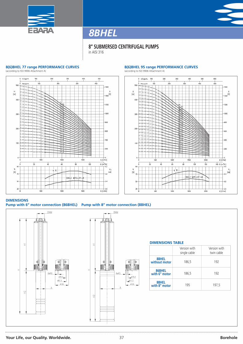
8(6)BHEL 77 range PERFORMANCE CURVES(according to ISO 9906 Attachment A)
8(6)BHEL 95 range PERFORMANCE CURVES(according to ISO 9906 Attachment A)
DIMENSIONSPump with 6” motor connection (86BHEL) Pump with 8” motor connection (8BHEL)
DIMENSIONS TABLE
8BHELwithout motor
86BHELwith 6" motor
8BHELwith 8" motor
Version withsingle cable
Version withtwin cable
192
192
197,5
186,5
186,5
195

Your Life, our Quality. Worldwide. 38 Borehole
DIMENSIONS TABLEModel Motor
sizeP2 Pump without motor Pump with motor in bath of liquid refrigerant Pump with motor in water bath
[HP] [kW] H1 DNM Weight A H2 H Weight A H2 H Weight[mm] [kg] [mm] [mm] [mm] [kg] [mm] [mm] [mm] [kg]
86 BHEL 77 - 2 6” 10 7,5 644 G5 31,5 139 600 1244 74 137 646 1290 -86 BHEL 77 - 3 6” 15 11 770 G5 36,5 139 700 1470 85 137 711 1481 -86 BHEL 77 - 4 6” 20 15 896 G5 41,5 139 760 1656 96 137 776 1672 9886 BHEL 77 - 5 6” 25 18,5 1022 G5 46,5 139 830 1852 112 137 842 1864 11086 BHEL 77 - 6 6” 30 22 1148 G5 51,0 139 890 2038 121 137 907 2055 12086 BHEL 77 - 7 6” 40 30 1274 G5 56,0 139 1030 2304 146 137 1037 2311 14086 BHEL 77 - 8 6” 40 30 1400 G5 61,0 139 1030 2430 151 137 1037 2437 14586 BHEL 77 - 9 6” 40 30 1526 G5 66,0 139 1030 2556 156 137 1037 2563 15086 BHEL 77 - 10 6” 50 37 1652 G5 71,0 - - - - 137 1405 3057 20686 BHEL 77 - 11 6” 50 37 1778 G5 76,0 - - - - 137 1405 3183 2118 BHEL 77 - 12 8” 60 45 1909 G5 82,0 - - - - 191 1077 2986 2278 BHEL 77 - 13 8” 75 55 2035 G5 87,0 - - - - 191 1204 3239 2628 BHEL 77 - 14 8” 75 55 2161 G5 92,0 - - - - 191 1204 3365 2678 BHEL 77 - 15 8” 75 55 2287 G5 97,0 - - - - 191 1204 3491 2728 BHEL 77 - 16 8” 100 75 2413 G5 101,5 - - - - 191 1395 3808 3158 BHEL 77 - 17 8” 100 75 2539 G5 106,5 - - - - 191 1395 3934 3208 BHEL 77 - 18 8” 100 75 2665 G5 111,5 - - - - 191 1395 4060 3258 BHEL 77 - 19 8” 100 75 2791 G5 116,5 - - - - 191 1395 4186 3308 BHEL 77 - 20 8” 100 75 2917 G5 121,0 - - - - 191 1395 4312 3348 BHEL 77 - 21 8” 100 75 3043 G5 126,0 - - - - 191 1395 4438 3398 BHEL 77 - 22 8” 125 93 3169 G5 131,0 - - - - 191 1747 4916 4228 BHEL 77 - 23 8” 125 93 3295 G5 136,0 - - - - 191 1747 5042 4278 BHEL 77 - 24 8” 125 93 3421 G5 141,0 - - - - 191 1747 5168 43286 BHEL 95 - 2 6” 12,5 9,2 644 G5 31,5 139 600 1244 77 137 678,7 1323 7986 BHEL 95 - 3 6” 20 15 770 G5 36,5 139 760 1530 91 137 776 1546 9386 BHEL 95 - 4 6” 25 18,5 896 G5 41,5 139 830 1726 107 137 842 1738 10586 BHEL 95 - 5 6” 30 22 1022 G5 46,0 139 890 1912 116 137 907 1929 11586 BHEL 95 - 6 6” 40 30 1148 G5 51,0 139 1030 2178 141 137 1037 2185 13586 BHEL 95 - 7 6” 40 30 1274 G5 56,0 139 1030 2304 146 137 1037 2311 14086 BHEL 95 - 8 6” 50 37 1400 G5 61,0 - - - - 137 1405 2805 19686 BHEL 95 - 9 6” 50 37 1526 G5 66,0 - - - - 137 1405 2931 2018 BHEL 95 - 10 8” 60 45 1657 G5 72,0 - - - - 191 1077 2734 2178 BHEL 95 - 11 8” 75 55 1783 G5 77,0 - - - - 191 1204 2987 2528 BHEL 95 - 12 8” 75 55 1909 G5 82,0 - - - - 191 1204 3113 2578 BHEL 95 - 13 8” 75 55 2035 G5 87,0 - - - - 191 1204 3239 2628 BHEL 95 - 14 8” 100 75 2161 G5 92,0 - - - - 191 1395 3556 3058 BHEL 95 - 15 8” 100 75 2287 G5 97,0 - - - - 191 1395 3682 3108 BHEL 95 - 16 8” 100 75 2413 G5 102,0 - - - - 191 1395 3808 3158 BHEL 95 - 17 8” 100 75 2539 G5 106,5 - - - - 191 1395 3934 3208 BHEL 95 - 18 8” 125 93 2665 G5 111,5 - - - - 191 1747 4412 4038 BHEL 95 - 19 8” 125 93 2791 G5 116,5 - - - - 191 1747 4538 4088 BHEL 95 - 20 8” 125 93 2917 G5 121,0 - - - - 191 1747 4664 4128 BHEL 95 - 21 8” 125 93 3043 G5 126,0 - - - - 191 1747 4790 4178 BHEL 95 - 22 8” 150 110 3169 G5 131,0 - - - - 191 1975 5144 4658 BHEL 95 - 23 8” 150 110 3295 G5 136,0 - - - - 191 1975 5270 470
8BHEL8” SUBMERSED CENTRIFUGAL PUMPSin AISI 316

Your Life, our Quality. Worldwide. 39 Borehole
8BHEL8” SUBMERSED CENTRIFUGAL PUMPSin AISI 316
SECTIONAL VIEW
MATERIALS TABLERef. Name Material Ref. Name Material10 00 5” discharge fitting EN 1.4401 (AISI 316) 30 01 Motor joint EN 1.4401 (AISI 316)+EN 1.4460 (AISI 329)10 01 Valve EN 1.4401 (AISI 316) 30 02 Upper thrust block washer EN 1.4460 (AISI 329)10 02 O-Ring NBR 30 03 Lower thrust block washer EN 1.4460 (AISI 329)10 03 Support screw and blocking EN 1.4401 (AISI 316) 30 04 Upper bearing (1) 9 stages or models SiC10 04 Valve seat EN 1.4401 (AISI 316) 30 05 Screw and washer (1) 17 stages or upper models EN 1.4401 (AISI 316)10 05 Seeger ring EN 1.4401 (AISI 316) 30 06 Thrust block PTFE10 06 Spring EN 1.4401 (AISI 316) 40 00 Stage EN 1.4401 (AISI 316)20 00 External casing EN 1.4401 (AISI 316) 40 01 Intermediate bush NBR20 01 Filter EN 1.4401 (AISI 316) 40 02 Wear ring PTFE20 02 Isolating cover EN 1.4401 (AISI 316) 40 03 Flange EN 1.4401 (AISI 316)20 03 Spacer EN 1.4401 (AISI 316) 50 00 Impeller EN 1.4401 (AISI 316)20 04 Flange and bolt EN 1.4401 (AISI 316) 50 01 Tapered ring EN 1.4401 (AISI 316)20 05 Motor support EN 1.4401 (AISI 316) 50 02 Fixing ring EN 1.4401 (AISI 316)30 00 Shaft EN 1.4460 (AISI 329)

Your Life, our Quality. Worldwide. 40 Borehole
ELECTRIC DATA TABLE 8(6)BHEL WITH MOTOR IN BATH OF LIQUID REFRIGERANT
ELECTRIC DATA TABLE 8(6)BHEL WITH MOTOR IN WATERBATH
Motor P2 P1 Voltage IN IA Efficiency Powerfactor
[HP] [kW] [kW] [V] [A] [A] [%]
6”
5,5 4 5,26 380/400 8,8 45 76 0,827,5 5,5 7,05 380/400 12,5 64 78 0,8210 7,5 9,74 380/400 16,9 78 77 0,82
12,5 9,2 11,50 380/400 21,5 95 80 0,8115 11 13,25 380/400 23,7 121 83 0,8320 15 18,29 380/400 30,4 160 82 0,8525 18,5 22,56 380/400 38,3 225 82 0,8530 22 26,51 380/400 44 250 83 0,8640 30 34,88 380/400 62 330 86 0,86
Motor P2 P1 Voltage IN IA Efficiency Powerfactor
[HP] [kW] [kW] [V] [A] [A] [%]
6”
5,5 4 5,13 400 9,3 43 78 0,827,5 5,5 6,96 400 12,5 64 79 0,8210 7,5 9,49 400 16 83 79 0,86
12,5 9,2 11,36 400 20,7 112 81 0,8015 11 13,58 400 23,3 129 81 0,8520 15 18,52 400 31,3 169 81 0,8525 18,5 22,56 400 38,5 231 82 0,8530 22 26,51 400 45,3 268 83 0,8440 30 36,14 400 63,5 393 83 0,8450 37 43,79 400 73 410 84,5 0,87
8”
60 45 51,72 400 89 645 87 0,8575 55 62,5 400 108 862 88 0,87100 75 86,21 400 145 1157 87 0,87125 93 106,9 400 190 1332 87 0,83150 110 125 400 222 1597 88 0,84
8BHEL8” SUBMERSED CENTRIFUGAL PUMPSin AISI 316
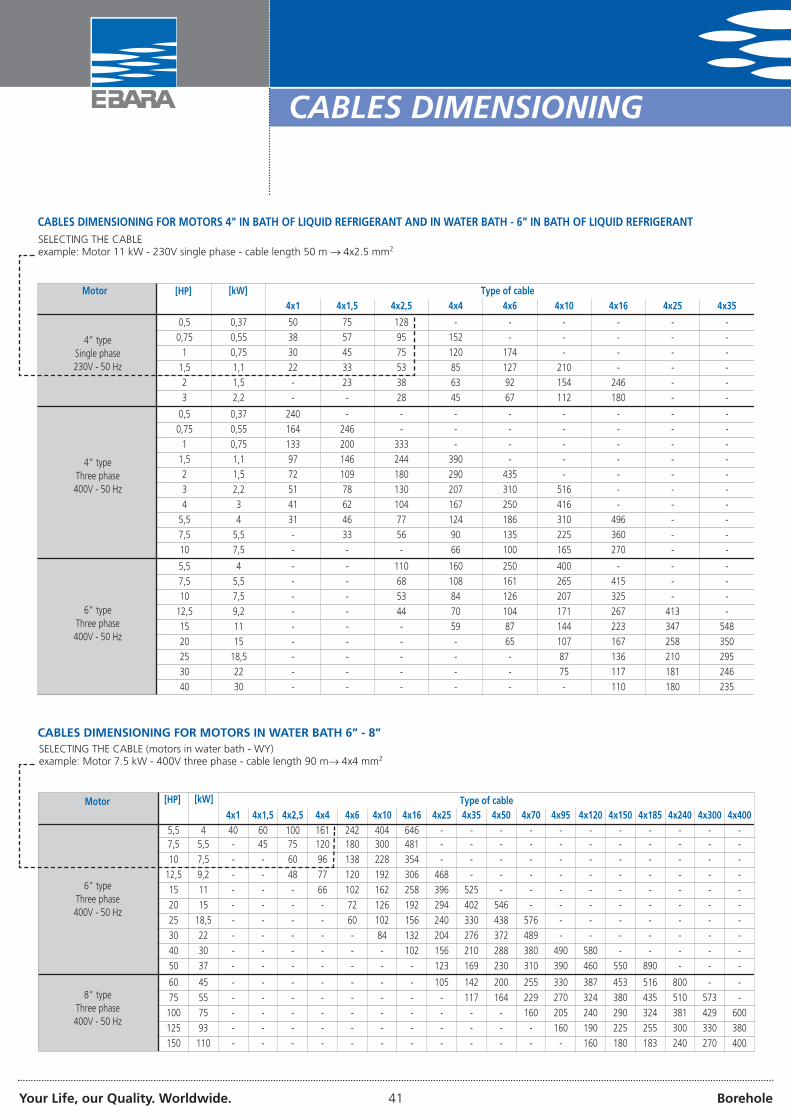
Your Life, our Quality. Worldwide. 41 Borehole
CABLES DIMENSIONING
CABLES DIMENSIONING FOR MOTORS 4" IN BATH OF LIQUID REFRIGERANT AND IN WATER BATH - 6” IN BATH OF LIQUID REFRIGERANT
CABLES DIMENSIONING FOR MOTORS IN WATER BATH 6” - 8”
Motor Type of cable4x1 4x1,5 4x2,5 4x4 4x6 4x10 4x16 4x25 4x35
0,5 0,37 50 75 128 - - - - - -
0,75 0,55 38 57 95 152 - - - - -
1 0,75 30 45 75 120 174 - - - -
1,5 1,1 22 33 53 85 127 210 - - -
2 1,5 - 23 38 63 92 154 246 - -
3 2,2 - - 28 45 67 112 180 - -
0,5 0,37 240 - - - - - - - -
0,75 0,55 164 246 - - - - - - -
1 0,75 133 200 333 - - - - - -
1,5 1,1 97 146 244 390 - - - - -
2 1,5 72 109 180 290 435 - - - -
3 2,2 51 78 130 207 310 516 - - -
4 3 41 62 104 167 250 416 - - -
5,5 4 31 46 77 124 186 310 496 - -
7,5 5,5 - 33 56 90 135 225 360 - -
10 7,5 - - - 66 100 165 270 - -
5,5 4 - - 110 160 250 400 - - -
7,5 5,5 - - 68 108 161 265 415 - -
10 7,5 - - 53 84 126 207 325 - -
12,5 9,2 - - 44 70 104 171 267 413 -
15 11 - - - 59 87 144 223 347 548
20 15 - - - - 65 107 167 258 350
25 18,5 - - - - - 87 136 210 295
30 22 - - - - - 75 117 181 246
40 30 - - - - - - 110 180 235
[HP] [kW]
SELECTING THE CABLEexample: Motor 11 kW - 230V single phase - cable length 50 m → 4x2.5 mm2
4” typeSingle phase230V - 50 Hz
4” typeThree phase400V - 50 Hz
6” typeThree phase400V - 50 Hz
4x1 4x1,5 4x2,5 4x4 4x6 4x10 4x16 4x25 4x35 4x50 4x70 4x95 4x120 4x150 4x185 4x240 4x300 4x4005,5 4 40 60 100 161 242 404 646 - - - - - - - - - - -7,5 5,5 - 45 75 120 180 300 481 - - - - - - - - - - -
10 7,5 - - 60 96 138 228 354 - - - - - - - - - - -
12,5 9,2 - - 48 77 120 192 306 468 - - - - - - - - - -
15 11 - - - 66 102 162 258 396 525 - - - - - - - - -
20 15 - - - - 72 126 192 294 402 546 - - - - - - - -
25 18,5 - - - - 60 102 156 240 330 438 576 - - - - - - -
30 22 - - - - - 84 132 204 276 372 489 - - - - - - -
40 30 - - - - - - 102 156 210 288 380 490 580 - - - - -
50 37 - - - - - - - 123 169 230 310 390 460 550 890 - - -
60 45 - - - - - - - 105 142 200 255 330 387 453 516 800 - -
75 55 - - - - - - - - 117 164 229 270 324 380 435 510 573 -
100 75 - - - - - - - - - - 160 205 240 290 324 381 429 600
125 93 - - - - - - - - - - - 160 190 225 255 300 330 380
150 110 - - - - - - - - - - - - 160 180 183 240 270 400
[HP] [kW]Motor
SELECTING THE CABLE (motors in water bath - WY)example: Motor 7.5 kW - 400V three phase - cable length 90 m→ 4x4 mm2
Type of cable
6” typeThree phase400V - 50 Hz
8” typeThree phase400V - 50 Hz

Your Life, our Quality. Worldwide. 42 Borehole
ELECTRIC CONTROL PANELS FOR SUBMERSED ELECTRIC PUMPS
The protection and control board for a submersed single phase electricpump.
The control panel is composed of a box in ABS with IP54 protectionrating and allows to control an electric motor with single phase powersupply.Thanks to the presence of a circuit breaker protection, it ensures theinterruption of motor functioning in the case of overcurrents.
TECHNICAL DETAILS• Controlling the electric pump via the luminous bi-polar switch• Motor protection via thermal cut-out with manual reset• Housing inside the capacitor for motor start-up.
ELECTRIC DATA TABLEModel Recommended capacitor
230V +10-15% - 50Hz single phase [HP] [kW] [A] [µF] [V]max
Q 0,50 M 16 0,5 0,37 4 16 450Q 0,50 M 20 0,5 0,37 4 20 450Q 0,75 M 20 0,75 0,55 6 20 450Q 0,75 M 25 0,75 0,55 6 25 450Q 1,00 M 35 1 0,75 7 35 450Q 1,50 M 40 1,5 1,1 9 40 450Q 0,50 M 16 2 1,5 12 50 450Q 0,50 M 16 2 1,5 12 60 450Q 0,50 M 16 3 2,2 18 70 450Q 0,50 M 16 3 2,2 18 80 450
The control panels Q are equipped with capacitor
Q SERIES
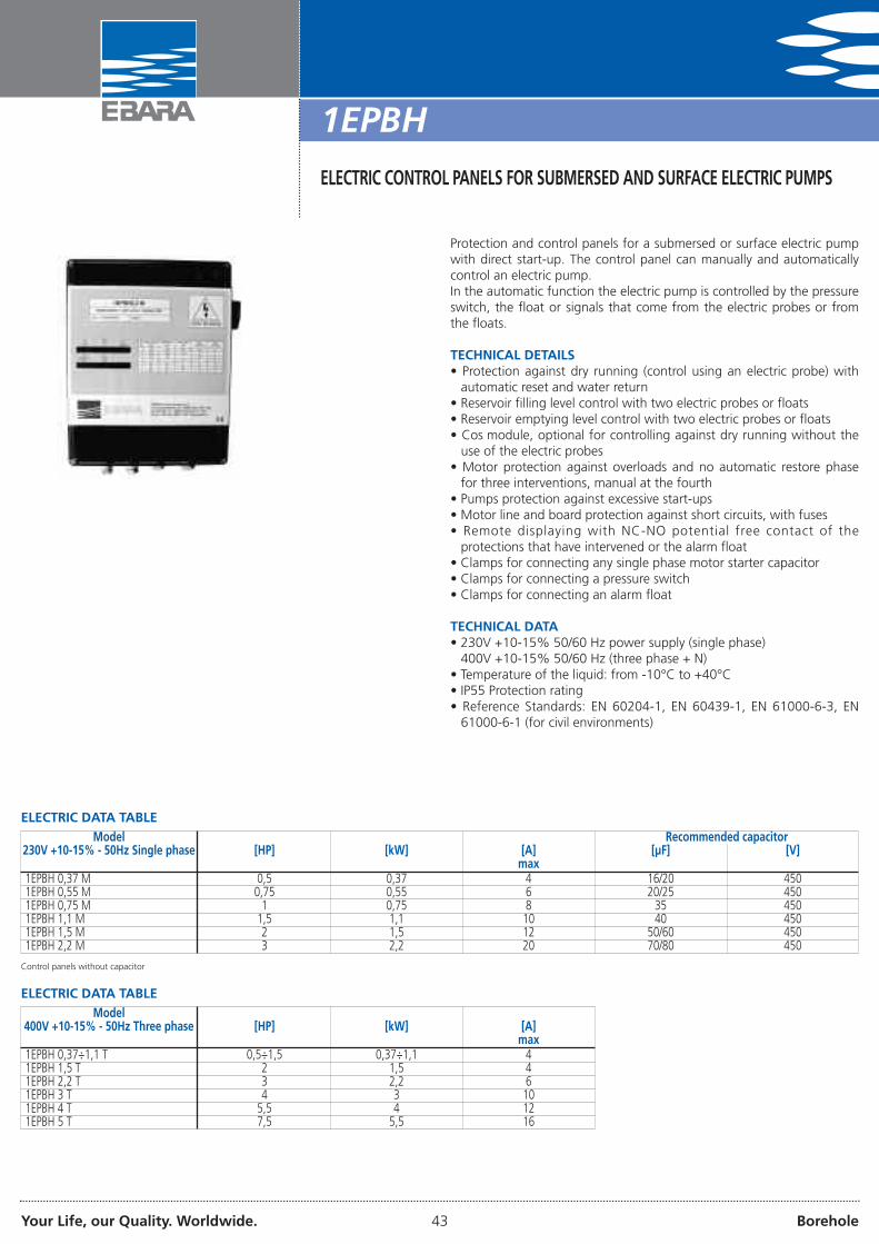
Your Life, our Quality. Worldwide. 43 Borehole
ELECTRIC CONTROL PANELS FOR SUBMERSED AND SURFACE ELECTRIC PUMPS
Protection and control panels for a submersed or surface electric pumpwith direct start-up. The control panel can manually and automaticallycontrol an electric pump.In the automatic function the electric pump is controlled by the pressureswitch, the float or signals that come from the electric probes or fromthe floats.
TECHNICAL DETAILS• Protection against dry running (control using an electric probe) with
automatic reset and water return• Reservoir filling level control with two electric probes or floats• Reservoir emptying level control with two electric probes or floats• Cos module, optional for controlling against dry running without the
use of the electric probes• Motor protection against overloads and no automatic restore phase
for three interventions, manual at the fourth• Pumps protection against excessive start-ups• Motor line and board protection against short circuits, with fuses• Remote displaying with NC-NO potential free contact of the
protections that have intervened or the alarm float• Clamps for connecting any single phase motor starter capacitor• Clamps for connecting a pressure switch• Clamps for connecting an alarm float
TECHNICAL DATA• 230V +10-15% 50/60 Hz power supply (single phase)
400V +10-15% 50/60 Hz (three phase + N)• Temperature of the liquid: from -10°C to +40°C• IP55 Protection rating• Reference Standards: EN 60204-1, EN 60439-1, EN 61000-6-3, EN
61000-6-1 (for civil environments)
ELECTRIC DATA TABLEModel Recommended capacitor
230V +10-15% - 50Hz Single phase [HP] [kW] [A] [µF] [V]max
1EPBH 0,37 M 0,5 0,37 4 16/20 4501EPBH 0,55 M 0,75 0,55 6 20/25 4501EPBH 0,75 M 1 0,75 8 35 4501EPBH 1,1 M 1,5 1,1 10 40 4501EPBH 1,5 M 2 1,5 12 50/60 4501EPBH 2,2 M 3 2,2 20 70/80 450
ELECTRIC DATA TABLEModel
400V +10-15% - 50Hz Three phase [HP] [kW] [A]max
1EPBH 0,37÷1,1 T 0,5÷1,5 0,37÷1,1 41EPBH 1,5 T 2 1,5 41EPBH 2,2 T 3 2,2 61EPBH 3 T 4 3 101EPBH 4 T 5,5 4 121EPBH 5 T 7,5 5,5 16
Control panels without capacitor
1EPBH
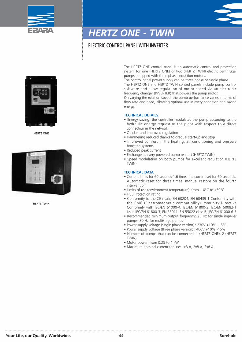
Your Life, our Quality. Worldwide. 44 Borehole
HERTZ ONE - TWINELECTRIC CONTROL PANEL WITH INVERTER
The HERTZ ONE control panel is an automatic control and protectionsystem for one (HERTZ ONE) or two (HERTZ TWIN) electric centrifugalpumps equipped with three phase induction motors.The control panel power supply can be three phase or single phase.The HERTZ ONE and HERTZ TWIN control panels include pump controlsoftware and allow regulation of motor speed via an electronicfrequency changer (INVERTER) that powers the pump motor.On varying the rotation speed, the pump performance varies in terms offlow rate and head, allowing optimal use in every condition and savingenergy.
TECHNICAL DETAILS• Energy saving: the controller modulates the pump according to the
hydraulic energy request of the plant with respect to a directconnection in the network
• Quicker and improved regulation• Hammering reduced thanks to gradual start-up and stop• Improved comfort in the heating, air conditioning and pressure
boosting systems• Reduced peak current• Exchange at every powered pump re-start (HERTZ TWIN)• Speed modulation on both pumps for excellent regulation (HERTZ
TWIN)
TECHNICAL DATA• Current limits for 60 seconds 1.6 times the current set for 60 seconds.
Automatic reset for three times, manual restore on the fourthintervention
• Limits of use (environment temperature): from -10°C to +50°C• IP55 Protection rating• Conformity to the CE mark, EN 60204, EN 60439-1 Conformity with
the EMC (Electromagnetic compatibil ity) Immunity DirectiveConformity with IEC/EN 61000-4, IEC/EN 61800-3, IEC/EN 50082-1Issue IEC/EN 61800-3, EN 55011, EN 55022 class B, IEC/EN 61000-6-3
• Recommended minimum output frequency: 25 Hz for single impellerpumps, 30 Hz for multistage pumps
• Power supply voltage (single phase version) : 230V +10% -15%• Power supply voltage (three phase version) : 400V +10% -15%• Number of pumps that can be connected: 1 (HERTZ ONE), 2 (HERTZ
TWIN)• Motor power: from 0.25 to 4 kW• Maximum nominal current for use: 1x8 A, 2x8 A, 3x8 A
HERTZ ONE
HERTZ TWIN

Your Life, our Quality. Worldwide. 45 Borehole
PRESSCOMFORT
PRESSCOMFORT is an automatic electronic appliance, destined toregulate the operation of the electric pump without using autoclavereservoirs.Water pump automatic start and stop control when a cock or valveconnected to the installation opens or closes respectively.When the pump is started, it continues until any cock connectedremains open, transmitting the requested flow rate at constant pressureto the network.If there is no suction air, the pump stops automatically.PRESSCOMFORT allows:- manual restore (RESET key)- automatic reset after 1, 6, 12 o 24 hours.If on suction the water, returns to a pressure exceeding the fixed value(1.5 bar) for pump start-up, PRESSCOMFORT is restored automatically.
TECHNICAL DETAILS• For electric pump, without tank, without probe, without float• PRESSCOMFORT wired - not wired• Automatic regulation• Incorporated non-return valve• Plate with functioning indicator• Connection cable on the pump terminal box (for wired version only)• Power supply cable (1.5 m) with standard socket (for wired version
only)
TECHNICAL DATA• Maximum temperature of the water: 60° C• Maximum flow rate: 10,000 l/h• Start-up pressure: 1.5 - 2.5 bar• Maximum use pressure: 10 bar• Power supply voltage: 220/240V - 50/60 Hz• Maximum current intensity: 10(6)A• IP65 Protection rating• G1 connections (pump and outlet side)
PRESSURE REGULATOR

Your Life, our Quality. Worldwide. 46 Borehole
Electronic device for controlling the electric pumps based on invertertechnology. Controls start-up and stop of the electric pump andmodulates the motor revs. depending on the withdrawal of water fromthe plant.
TECHNICAL DETAILS• Constant pressure thanks to the regulation of the electric pump revs.• Energy saving thanks to lower pump absorption• Gradual pump start-up and stop that reduce hammering and
eliminate peak current on ignition• Protection against dry running if there is no suction air• Reset automatic in the case of stopping due to dry running, able to
autonomously solve the error condition• Effective leak control for the protection of the pump in the case of
continuous re-starts• Digital indication of the pressure on the display• Amperometric motor control• Indication of the various functioning/error states via luminous
indicators and messages on the display• Functioning in twin units alternately• Double set-point that can be controlled at a distance• Electric pump remote start and stop• Rotation direction inversion via software (does not require
interventions on wiring)• Removable electric clamps to easy wiring• For correct functioning of the systems with Press•o•Matic, he use of
an expansion vessel is recommended
TECHNICAL DATA• Mains power supply: single phase 230V ± 10%, 50Hz• Motor output: three phase 220V• Maximum motor power: 2200W - 3HP• Maximum line absorption: 16A at 230V• Maximum pressure accepted: 8 bar• Maximum temperature of the liquid: 50°C• Pressure drop: 0.1 bar at 150 l/min• Set-point regulation range: 1.5÷7 bar• Start pressure regulation range: 1÷6.7 bar• Hydraulic connection: G1¼ male-male• Frequency modulation range: 25÷50 Hz• Protection rating: IP 65
VERSIONI SPECIALI• Frequency modulation range 30÷60 Hz• Connection cable for functioning in pairs 4x0.5 mm2 100 (SR-
CBL4X05-100)
1~230V
3~220V
3~220V
1~230V
è
è
èè
è
è
Traditional on-off device
Press•o•Matic with inverter technology (set-point 2,0 bar)
143
147
254
PRESSURE-FLOW RATE GRAPHICS (ELECTRIC PUMP 1.5 HP)
PRESS •O•MATIC
INVERTER FOR CONTROLLING THE ELECTRIC PUMPS

Your Life, our Quality. Worldwide. 47 Borehole
PRESSURE LOSS TABLE
[m3/h] 25 32 40 50 60 70 80 90 100 125 150 175 200 225 250 275 300 350 400 450 500 600 700 800 900 1000
3 Pc %Vm/s
171,70
61,03
1,60,67
0,540,43
0,250,29
0,130,22
0,060,16
0,030,13
0,020,10
6 Pc %Vm/s
242,06
61,34
20,85
0,90,58
0,430,44
0,210,32
0,130,26
0,080,20
0,0260,13
9 Pc %Vm/s
12,52,08
4,31,32
1,80,89
0,90,65
0,460,5
0,250,39
0,150,32
0,060,20
12 Pc %Vm/s
202,76
71,76
3,21,19
1,50,88
0,750,67
0,440,53
0,250,43
0,090,27
0,030,18
15 Pc %Vm/s
122,2
5,21,49
2,41,1
1,250,87
0,70,66
0,420,54
0,150,34
0,060,24
18 Pc %Vm/s
172,64
71,78
3,51,3
1,71
10,78
0,60,64
0,20,4
0,080,28
21 Pc %Vm/s
223,35
8,82,08
4,21,54
2,21,17
1,30,93
0,750,75
0,260,48
0,10,32
0,050,24
24 Pc %Vm/s
122,38
5,71,76
31,34
1,71,06
10,86
0,360,54
0,140,36
0,070,28
27 Pc %Vm/s
142,7
71,97
3,51,45
21,17
1,250,96
0,420,6
0,170,42
0,080,31
30 Pc %Vm/s
172,98
8,22,2
4,21,74
2,51,32
1,51,08
0,50,68
0,20,48
0,090,34
36 Pc %Vm/s
253,58
122,63
6,32
3,51,58
21,28
0,750,82
0,30,57
0,140,42
0,070,32
42 Pc %Vm/s
163,07
8,52,34
4,51,85
2,71,5
0,850,96
0,330,66
0,180,48
0,080,37
48 Pc %Vm/s
213,51
102,68
62,12
3,61,72
1,21,08
0,450,72
0,220,56
0,120,43
0,060,34
54 Pc %Vm/s
253,94
13,53
7,62,34
4,51,92
1,51,2
0,550,84
0,280,63
0,140,48
0,080,38
60 Pc %Vm/s
163,32
92,64
5,52,16
1,81,36
0,70,96
0,330,68
0,170,53
0,10,42
75 Pc %Vm/s
244,17
143,31
82,68
2,761,72
11,18
0,490,87
0,240,67
0,140,53
0,080,43
90 Pc %Vm/s
203,97
12,53,24
3,82,04
1,451,44
0,741,02
0,360,8
0,20,63
0,140,51
0,080,42
105 Pc %Vm/s
264,6
16,53,74
5,32,41
1,951,66
0,91,22
0,470,93
0,270,74
0,160,59
0,10,49
120 Pc %Vm/s
21,54,31
6,92,72
2,61,93
1,21,35
0,611,06
0,360,84
0,20,68
0,140,56
0,080,47
135 Pc %Vm/s
264,81
91,07
3,32,13
1,51,56
0,761,19
0,450,95
0,250,76
0,170,63
0,10,53
150 Pc %Vm/s
113,44
42,36
1,91,74
0,951,34
0,551,05
0,30,86
0,210,70
0,120,59
0,060,43
165 Pc %Vm/s
133,75
4,72,61
2,21,91
1,131,46
0,651,15
0,370,94
0,240,77
0,150,65
0,080,48
180 Pc %Vm/s
15,24,09
5,52,83
2,62,08
1,31,59
0,761,26
0,431,02
0,290,84
0,180,71
0,090,52
210 Pc %Vm/s
214,70
7,43,32
3,52,43
1,81,86
1,11,49
0,61,19
0,370,98
0,240,82
0,120,61
0,060,47
240 Pc %Vm/s
9,43,78
4,32,77
2,32,12
1,31,68
0,751,36
0,481,12
0,30,95
0,150,69
0,080,53
270 Pc %Vm/s
124,26
5,53,13
2,82,39
1,621,90
0,91,53
0,581,26
0,351,07
0,180,78
0,090,59
300 Pc %Vm/s
144,75
7,53,47
3,42,66
22,10
1,11,71
0,741,40
0,461,18
0,220,86
0,110,67
0,070,53
360 Pc %Vm/s
94,15
4,73,17
2,82,53
1,62,04
11,68
0,651,41
0,321,04
0,160,79
0,090,63
0,050,51
420 Pc %Vm/s
11,64,86
6,23,72
3,52,94
22,37
1,31,96
0,821,64
0,411,22
0,210,94
0,120,76
0,070,59
0,030,41
480 Pc %Vm/s
8,54,24
4,93,36
2,92,72
1,92,24
1,21,90
0,61,38
0,31,06
0,170,84
0,090,69
0,040,47
540 Pc %Vm/s
114,78
6,53,80
3,73,06
2,352,52
1,522,13
0,751,56
0,381,19
0,220,94
0,120,76
0,050,53
600 Pc %Vm/s
12,25,30
7,44,20
4,33,40
2,72,81
1,72,36
0,91,73
0,451,34
0,251,06
0,130,86
0,0550,61
0,0240,44
660 Pc %Vm/s
94,61
5,23,76
3,33,07
2,12,59
1,11,89
0,541,46
0,30,15
0,160,93
0,060,65
0,030,48
720 Pc %Vm/s
105,05
64,08
3,83,37
2,52,84
1,32,08
0,521,65
0,351,26
0,191,02
0,0750,71
0,0350,52
780 Pc %Vm/s
7,34,43
4,53,65
33,08
1,52,26
0,751,73
0,421,36
0,231,11
0,080,77
0,040,56
840 Pc %Vm/s
84,76
5,43,95
3,43,31
1,72,43
0,851,86
0,481,47
0,261,19
0,10,83
0,0470,61
900 Pc %Vm/s
95,1
5,84,22
3,753,54
1,92,60
0,962,00
0,531,57
0,291,27
0,110,88
0,0530,65
960 Pc %Vm/s
6,54,49
4,33,78
2,12,77
1,12,13
0,61,68
0,321,36
0,120,95
0,060,70
1020 Pc %Vm/s
7,24,76
4,64,01
2,452,94
1,22,26
0,671,78
0,351,44
0,141,00
0,0650,77
0,0330,54
1080 Pc %Vm/s
5,44,26
2,83,12
1,42,38
0,781,86
0,431,53
0,161,06
0,0730,78
0,0370,57
1140 Pc %Vm/s
64,49
3,23,29
1,532,53
0,861,99
0,461,65
0,1751,12
0,080,84
0,0430,61
0,0370,52
1200 Pc %Vm/s
6,54,72
3,43,45
1,72,68
0,932,12
0,51,72
0,191,23
0,090,88
0,0460,63
0,040,54
0,0250,4
Pressure drop (Pc) in metres of column of water for every one hundred metres of new cast iron pipe. Speed of the liquid in the pipe in metres/second.
It is possible to estimate the pressure drops caused byaccessories with the following comparisons:
- Foot valve: like 15 m of piping- Non-return valve: like 10 m of piping- Gate: like 5 m of piping- Bends and elbows: like 5 m of piping
Flow rate Internal diameter [mm]
For piping different to the new cast iron ones, multiply thetable data for the following coefficients:- stainless steel . . . . . . . . . . . . . . . . . . . . . . . . . . . . . . . 0,8- PVC . . . . . . . . . . . . . . . . . . . . . . . . . . . . . . . . . . . . . 0,7- gres . . . . . . . . . . . . . . . . . . . . . . . . . . . . . . . . . . . . 1,17- rolled steel . . . . . . . . . . . . . . . . . . . . . . . . . . . . 0,8- galvanised steel . . . . . . . . . . . . . . . . . . . . . . . . . . . . . 0,8- slightly rusty pipes . . . . . . . . . . . . . . . . . . 1,25- rust pipes with a lot of deposits . . . . . . . . . . . . . . . . . 2,1
Recommended discharge diameter
Recommended suction diameter
Your Life, our Quality. Worldwide. 48 Borehole
SPECIFIC PERFORMANCEThe specifications given refer to the curves illustrated in our catalogues and Data Book (see www.ebaraeurope.com).All of the performance curves are calculated according to ISO 9906 Attachment A.
Tolerance according to ISO 9906 Annex A.The curves refer to an effective speed of the 50 Hz asynchronous motors.The measurements are made with water temperature of 20°C and cinematic viscosity of = 1 mm2/s (1 cSt).In order to prevent the risk of overheating, the pumps must not be used at a flow rate below 10% of the maximum efficiency flow rate.During selection of the pumps, there is a safety margin of at least 1 m.
Symbols: Q = Flow rate [m3/h]H = Head [m]P1 = Power absorbed by the electric lineP2 = Power yielded to the motor axis (power absorbed by the pump)